

Page 1

Universal RAID Utility
Ver 2.0
User's Guide
2nd Edition
March 2009
808-882328-450-B
Page 2

Trademarks
NEC ESMPRO and NEC EXPRESSBUILDER are trademarks of NEC Corporation.
Microsoft and its logo, Windows, Windows Server, and MS-DOS are registered trademarks of Microsoft Corporation in the
United States and other countries.
"Linux" is a registered trademark or a trademark in United States or other countries of Linus Torvalds.
Red Hat, Red Hat Enterprise Linux, the Shadowman logo and JBoss are registered trademarks of Red Hat, Inc. in the U.S. and
other countries.
The name and logo of "Asianux" is a trademark of Miracle Linux Corporation and Red Flag Software Co., Ltd.
Asianux is a registered trademark in Japan of MIRACLE LINUX Corporation.
VMware is a registered trademark of VMware, Inc. in the United States and/or other jurisdictions.
All other product, brand, or trade names used in this publication are the trademarks or registered trademarks of their
respective trademark owners.
Notes
1. No part of this manual may be reproduced in any form without the prior written permission of NEC Corporation.
2. The contents of this manual may be revised without prior notice.
3. The contents of this manual shall not be copied or altered without the prior written permission of NEC Corporation.
4. All efforts have been made to ensure the accuracy of all information in this manual. If you notice any part unclear,
5. NEC assumes no liability arising from the use of this product, nor any liability for incidental or consequential damages
incorrect, or omitted in this manual, contact the sales agent where you purchased this product.
arising from the use of this manual regardless of Item 4.
2
Page 3

Introduction
This User’s Guide describes RAID System management utility "Universal RAID Utility Ver 2.0".
See "Appendix A : Glossary" for the terms on the Universal RAID Utility and those used in this User’s Guide.
"Universal RAID Utility" means "Universal RAID Utility Ver 2.0".
Before the Universal RAID Utility can be used, you should carefully read the User’s Guide of the RAID System
managed by the Universal RAID Utility and that of the computer in which the RAID System is installed.
The User’s Guide is intended to be read by engineers who are fully familiar with the functions and operations of
Windows and Linux. Refer to the Window and Linux online help and related documentation for the operations and
concerns of Windows and Linux.
Symbols used in the text
The User’s Guide uses the following three symbols. Follow these symbols and their meanings to use the Universal
RAID Utility appropriately.
Symbol Description
Indicates a matter or caution you should particularly obey on operations of the Universal RAID Utility.
Indicates a notice you should check to operate the Universal RAID Utility.
Indicates effective or convenient information which help you if you know them.
3 4
Page 4

Contents
Overview 8
What is Universal RAID Utility? 8
Structure of Universal RAID Utility 9
Functional difference from Universal RAID Utility Ver1.4 10
Setup of Universal RAID Utility 12
Operation Environments 12
Hardware 12
Software (Windows) 12
Software (Linux) 13
Software (VMware ESX Server) 13
Others 13
Installation and Uninstallation 15
Preparing installation (Windows) 16
New Installation (Windows) 17
Update Installation (Windows) 18
Add Installation (Windows) 19
Uninstallation (Windows) 20
Preparing installation (Linux) 21
New Installation (Linux, VMware ESX Server) 21
Update Installation (Linux, VMware ESX Server) 22
Add Installation (Linux, VMware ESX Server) 22
Uninstallation (Linux, VMware ESX Server) 22
Starting or Stopping Universal RAID Utility 23
raidsrv service 23
Starting Universal RAID Utility in Single User Mode 23
RAID Viewer 24
Log Viewer 25
raidcmd 26
Standard and Advanced Modes 27
Running Mode when startup RAID Viewer and raidcmd 28
Changing Running Mode 28
Functions of RAID Viewer 29
Structure of RAID Viewer 29
Tree View 29
Computer 30
RAID Controller 30
Battery 30
Disk Array 30
Logical Drive 31
Physical Device 31
Shortcut Menu 31
Operation View 32
Menu Bar 33
[File] menu 33
[Control] menu 33
[Tool] menu 34
[Help] menu 34
Page 5

Status Bar 35
Functions of Log Viewer 36
Structure of Log Viewer 36
Log View 37
Menu Bar 37
[File] menu 37
[Help] menu 38
Functions of raidcmd 39
Command Line 39
Returned Value from raidcmd 39
Error Messages of raidcmd 39
Commands of raidcmd 39
Termination of raidcmd 39
Referring to Information on RAID System 40
Referring to Property of RAID Controller 40
Referring to Property of Battery 41
Referring to Property of Logical Drive 42
Referring to Property of Physical Device 44
Referring to Property of Disk Array 45
Checking Execution Status of Operation 46
Updating Information of RAID System 47
Referring to RAID System Operation Log 47
Configuration of RAID System 48
Making Hot Spare 49
About Global Hot Spare 49
About Dedicated Hot Spare 50
Making Global Hot Spare 51
Making Dedicated Hot Spare 52
Removing Hot Spare 53
Configuring RAID System Easily 54
Procedure of Easy Configuration of RAID System 54
RAID Controller Enabling Easy Configuration to Be Executed 56
Physical Devices Available for Easy Configuration 56
Creating Logical Drives by Easy Configuration 57
Making Hot Spares by Easy Configuration 59
Creating Logical Drive Easily 61
Operation Procedure of "Create Logical Drive - Simple Mode" 61
Physical Devices Available for "Create Logical Drive - Simple Mode" 63
Creating Logical Drives by "Create Logical Drive - Simple Mode" 63
Creating Logical Drive Freely 64
Operation Procedure of "Create Logical Drive - Custom Mode" 64
Disk Arrays and Physical Devices Available for "Create Logical Drive - Custom Mode" 67
Creating Logical Drives by "Create Logical Drive - Custom Mode" 68
Deleting Logical Drive 69
Deleting Logical Drive 69
Maintenance of RAID System 70
Providing Patrol Read for Physical Devices 70
Setting Whether Patrol Read Is Executed or Not 70
Checking Result of Executing Patrol Read 71
5
Page 6

Setting Patrol Read Priority 71
Checking Logical Drive Consistency 72
Executing Consistency Check Manually 72
Executing Consistency Check for arbitrary Logical Drive 73
Stopping Consistency Check 73
Checking Result of Executing Consistency Check 74
Setting Consistency Check Priority 74
Initializing Logical Drive 76
Executing Initialization 76
Stopping Initialization 77
Checking Result of Executing Initialization 77
Setting Initialization Priority 77
Rebuilding Physical Device 79
Executing Rebuild 79
Stopping Rebuild 80
Checking Result of Executing Rebuild 80
Setting Rebuild Priority 80
Checking Location of Physical Device 82
Procedure of Checking Location of Physical Device 82
Changing Status of Physical Device Forcibly 83
To [Online] Forcibly 83
To [Failed] Forcibly 84
Troubleshooting RAID System 85
Failure Detection Measures 86
Status Display by RAID Viewer 86
Status Display by raidcmd 86
Logging Events to RAID Log 86
Buzzer in RAID Controller 86
Logging Events to OS Log 87
Sending Alert to NEC ESMPRO Manager 87
Monitoring Faults of Physical Devices 88
Operation in no failures of Physical Devices 89
Operation when redundancy of Logical Drive degraded or lost due to failure of Physical Device 90
Operation when failed Physical Device is replaced to recover RAID System 91
Operation when the Logical Drive is offline due to failure of Physical Device 92
Monitoring Battery Status 93
Monitoring Enclosure Status 94
Monitoring Various Events of RAID System 94
Replacing Physical Device for Prevention 94
Changing of Settings of Universal RAID Utility 96
Changing TCP port number 96
Using Windows as Operating System 96
Using Linux or VMware ESX Server as Operating System 97
Changing Running Mode at Start of RAID Viewer 97
raidcmd Command Reference 98
cc 98
ccs 98
delld 98
econfig 99
help 99
hotspare 99
init 100
mkldc 100
6
Page 7

mklds 102
oplist 103
optctrl 103
optld 104
property 104
rebuild 105
rescan 105
runmode 105
sbuzzer 106
slotlamp 106
stspd 106
Notes on Use of Universal RAID Utility 108
Operation Environment 108
Use of IPv6 108
Use of Universal RAID Utility from Remote System 108
RAID Viewer, Log Viewer 108
Verification authenticode signature when startup the RAID Viewer and Log Viewer 108
Appendix A : Glossary 109
Basic Terms on RAID System 109
Basic Terms on Functions of RAID System 110
Basic Terms on Universal RAID Utility 110
Appendix B : Logs/Events 111
7
Page 8

Overview
This chapter describes the overview of the Universal RAID Utility.
What is Universal RAID Utility?
The Universal RAID Utility enables RAID Systems in a computer to be managed.
The Universal RAID Utility is characterized as follows.
1. Allowing a variety of RAID Systems to be managed
Conventionally, a specific management utility must be used for each RAID System. On the other hand, only the
Universal RAID Utility can manage more than one RAID System. For the RAID Systems which the Universal
RAID Utility can manage, refer to the documentation on computers and RAID Systems.
2. Operating in either Standard or Advanced Mode
The Universal RAID Utility can operate in two running modes, which are Standard Mode and Advanced Modes.
The Standard Mode provides the Universal RAID Utility with standard management functions of RAID Systems.
The Advanced Mode provides the Universal RAID Utility with advanced management and maintenance
functions of RAID Systems.
Using the two running modes appropriately depending on users and jobs allows the usability of the Universal
RAID Utility to be improved and malfunctions to be avoided.
3. Configuring RAID Systems easily
Using the Universal RAID Utility, you can configure a RAID System easily without expert knowledge of the RAID
System.
The Universal RAID Utility provides the "simple Logical Drive create function" allowing a Logical Drive to be
created by selecting only two selection items according to the guide of the Universal RAID Utility and the "Easy
Configuration" allowing a RAID System to be configured only by defining uses of unused Physical Devices.
4. Supporting general functions required for configurations, operations and maintenances of RAID Systems
The Universal RAID Utility supports general functions for configuring a RAID System (including creating Logical
Drive and making Hot Spare), general operation functions (including log recording, Patrol Read and Consistency
Check), and general functions required for maintenance (including Rebuild and Locate functions).
5. Troubleshooting RAID Systems
The Universal RAID Utility can detect failures occurred in RAID Systems by using various functions.
The RAID Viewer, the GUI of the Universal RAID Utility, indicates the configurations and status of RAID Systems
comprehensibly with trees and icons. The raidcmd, the CLI of the Universal RAID Utility, indicates the same
information too. In addition, the Universal RAID Utility registers failures occurred in RAID Systems not only to
the dedicated log but also the OS log. Further, the Universal RAID Utility can send alerts to the NEC ESMPRO
Manager normally attached to NEC Express series systems.
8
Page 9
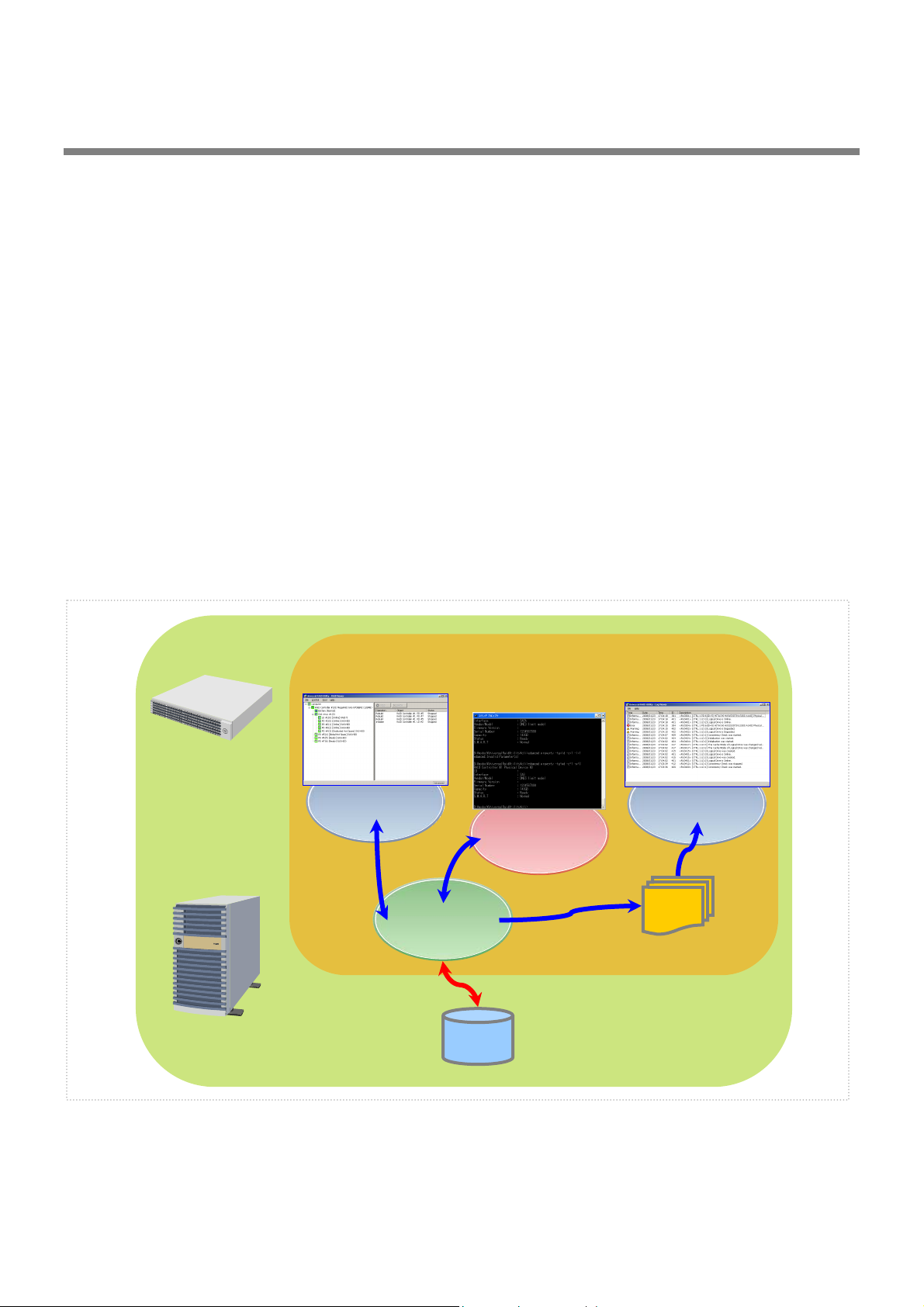
y
Structure of Universal RAID Utility
The Universal RAID Utility consists of the following modules:
raidsrv service
The raidsrv service always operates in the computer to manage RAID Systems. Receiving a processing request
from the RAID Viewer or raidcmd, the raidsrv service provides proper information on a RAID System or
performs an appropriate operation for the RAID System. In addition, the raidsrv service manages events
occurred in RAID Systems, notifies the RAID Viewer of the events and/or registers them to several logs.
RAID Viewer
The RAID Viewer is the Windows application managing and monitoring the RAID system by GUI. The RAID
Viewer displays the configuration and status of a RAID System graphically or provides configuration and
operation for a RAID System.
Log Viewer
The Log Viewer is the Windows application viewing the event of RAID system. The Log Viewer allows you to see
the RAID Log in which events occurred in RAID Systems are registered.
raidcmd
The raidcmd is the application managing and monitoring the RAID system by CLI.
The raidcmd is the command that indicates the configuration and status of a RAID System or operates on a
console providing configurations and operations.
Universal RAID Utilit
Computer
RAID
Viewer
raidcmd
raidsrv
service
Log Viewer
RAID Log
RAID System
Figure 1 Configuration of Universal RAID Utility
9
Page 10

The usable modules are different by the version of Universal RAID Utility or the kind of operating system. See the
following table for detail.
Operating System Windows Linux VMware ESX Server
raidsrv service
RAID Viewer
Log Viewer
raidcmd
Functional difference from Universal RAID Utility Ver1.4
Universal RAID Utility Ver2.0 executed the functional enhancement and the function change in the following from
Ver1.4.
1. Addition of hardware for management
"Promise RAID Controller" is added to the RAID Controller for management
SSD(Solid State Drive) is supported
HDD and SSD can be distinguished by the item of the device type in the property of a Physical Device.
See "Referring to Property of Physical Device".
HDD and SSD cannot exist together in the same Logical Drive. Be careful when creates a Logical Drive
or create the Hot Spare.
Physical Devices other than HDD(SSD is included) are managed
The tape device, the CD drive, and the DVD drive connected with the RAID controller can be referred to
in the tree view and property. However, the state monitoring functions of a physical device other than
HDD (SSD is included) are not supported.
2. Configuration
The condition that a logical drive can be deleted is changed
You are not able to delete a Logical Drive with boot partition until Ver 1.4.
The condition of the Logical Drive that was able to be deleted was changed in Ver 2.0. For detail, see
"Deleting Logical Drive".
3. Operation
The initialization execution condition of a logical drive is changed
You are not able to initialize a Logical Drive with boot partition until Ver1.4.
The condition of the Logical Drive that was able to be initialized was changed in Ver2.0. For detail, see
"Initializing Logical Drive".
Timing in which the Patrol Read is executed is changed
The Patrol Read was executed always continuously until Ver1.4.
The timing in which the Patrol Read is executed is changed in Ver2.0. For detail, see "Providing Patrol
Read for Physical Devices".
The way of turn off the lamp for checking location of Physical Device is changed
To turn off the lamp for checking location of Physical Device, always use the RAID Viewer or raidcmd
until Ver1.40. When the fixed time had passed since the lamp was turned on, the function to
turn off the lamp was added in Ver2.0.
4. Display of information
The tree view of the RAID viewer is changed
The Disk Array and the Battery were newly displayed as a node, and the entire tree composition was
changed. For detail, see "Tree View".
The design of the icon used by the RAID viewer is changed
10
Page 11

Use the omission mark in the RAID Viewer and raidcmd. The Logical Drive is displayed as "LD" and
Physical Device is displayed as "PD".
"Queued" and "Paused" is added to the status of operation
The update function about information of RAID system is added
Supports "Rescan" of RAID Viewer and "rescan" command of raidcmd as the function which updates
the managed information in the Universal RAID Utility in Ver 2.0. Deleted the old "Rescan" function of
RAID Viewer of Ver1.4.
5. Log/Event
For detail, see "Appendix B : Logs/Events".
Change address description in the event of Physical Device
It became one parameter though the vendor and model of a Physical Device were separate
parameters.
Add Log/Event
ID : 0213 - 0217, 0321 - 0324, 0426 - 0434, 0509, 0607
Change content of Log/Event
ID : 0319, 0320, 0413, 0422, 0423, 702
6. Usability
Add help function of raidcmd
For detail, see "help".
11
Page 12

Setup of Universal RAID Utility
This chapter describes installation or uninstallation of the Universal RAID Utility.
Operation Environments
The Universal RAID Utility can operate in the following environments.
Hardware
Computers
The computers can contain RAID Systems to be managed by the Universal RAID Utility.
RAID Systems to be managed by Universal RAID Utility
For RAID Systems which can be managed by the Universal RAID Utility, refer to the documentation attached
to the computer in which RAID Systems are installed and that attached to the RAID Controller including the
Universal RAID Utility.
Software (Windows)
Operating systems
The Universal RAID Utility can operate in the following operating systems.
It can operate in either 32-bit or 64-bit environment for any operating system other than Windows 2000.
Windows Server 2008
Windows Server 2003 R2 SP1 or later
Windows Server 2003 SP1 or later
Windows 2000 SP4
Windows Vista
Windows XP Professional SP2 or later
If you use "Server Core Install Option" of Windows Server 2008, you can use raidcmd for the
management of the RAID system only (You can not use RAID Viewer and Log Viewer).
Microsoft .NET Framework
To use the Universal RAID Utility, Microsoft .NET Framework Version 2.0 or higher is required.
If the operating system installed in your computer is any of those listed below, install Microsoft .NET
Framework Version 2.0:
Windows Server 2003 R2 SP1 or later
Windows Server 2003 SP1 or later
Windows 2000 SP4
Windows XP Professional SP2 or later
For the installation of Microsoft .NET Framework Version 2.0 or higher, see "Preparing installation
(Windows)".
12 13
Page 13

Runtime component of Microsoft Visual C++ library
To use the Universal RAID Utility, the runtime component of the Microsoft Visual C++ library is required.
For the installation of the runtime component of the Microsoft Visual C++ library, see "Preparing installation
(Windows)".
Software (Linux)
Operating systems
The Universal RAID Utility can operate in the following operating systems.
It can operate in either 32-bit or 64-bit environment for any operating system.
Red Hat Enterprise Linux 4.5 or later
Red Hat Enterprise Linux 5.1 or later
MIRACLE LINUX V4.0 SP 2 or later
Asianux Server 3
Software (VMware ESX Server)
VMware ESX Server
The Universal RAID Utility can operate in the following VMware ESX Server.
VMware ESX 3.5 Update 1 or later
You must install the Universal RAID Utility in the ESX Server. Don't install in the virtual machine.
Others
System Requirements
Resource Windows Linux/VMware ESX Server
Available Hard Disk Space 50MB or more
(not include Microsoft .NET Framework
Ver2.0 、the runtime of Microsoft Visual
C++ 2005 SP1 library)
RAM 512MB or more
TCP ports used by Universal RAID Utility
(not include the required packages as
standard C++ library...etc)
←
←
The Universal RAID Utility uses the following two TCP ports.
TCP ports used by Universal RAID Utility
52805 and 52806
For the change of TCP ports number using Universal RAID Utility, see "Changing TCP port number".
Page 14

Safe Mode and Single User Mode
The Universal RAID Utility uses the network function. Accordingly, the Universal RAID Utility is unavailable in
any of the following safe modes in which the network function cannot operate.
Safe Mode
Safe Mode with Command Prompt
Safe Mode with Networking
Also, cannot be used in the single user mode of Linux and VMware ESX Server. For how to use the Universal
RAID Utility in the single user mode, see "Starting Universal RAID Utility in Single User Mode".
14
Page 15

Installation and Uninstallation
This section describes the procedure of installation and uninstallation of Universal RAID Utility.
The working procedure is different by the kind of installation or uninstallation.
kind Description
New Installation Install Universal RAID Utility newly, when there is not Universal RAID Utility in the computer.
Procedure (Windows)
1. Preparing installation (Windows)
2. New Installation (Windows)
Procedure (Linux)
1. Preparing installation (Linux)
2. New Installation (Linux, VMware ESX Server)
Procedure (VMware ESX Server)
1. New Installation (Linux, VMware ESX Server)
Update Installation Install the new version of Universal RAID Utility, when there is the old version of Universal
RAID Utility in the computer
Procedure (Windows)
1. Update Installation (Windows)
Procedure (Linux、VMware ESX Server)
1. Update Installation (Linux, VMware ESX Server)
Add Installation Install or uninstall the program to control the RAID Controller after added or deleted the RAID
Controller.
Procedure (Windows)
1. Add Installation (Windows)
Procedure (Linux、VMware ESX Server)
1. Add Installation (Linux, VMware ESX Server)
Uninstallation Uninstall Universal RAID Utility from the computer.
Procedure (Windows)
1. Uninstallation (Windows)
Procedure (Linux、VMware ESX Server)
1. Uninstallation (Linux, VMware ESX Server)
Use the setup program of Universal RAID Utility for the installation and the uninstallation.
The setup program is contained in the installation image of the Universal RAID Utility. Before the Universal RAID Utility
can be installed or uninstalled, you must prepare the installation image.
The setup program of Windows is " setup.exe". The setup program of Linux and VMware ESX Server is "setup.sh".
The installation image of the Universal RAID Utility for Windows and Linux is contained in
an accessory of the computer or RAID Controller.
About Universal RAID Utility for VMware ESX Server, please contact our support.
15
Page 16
A user having the administrator authority should install or uninstall the Universal RAID
Utility in the computer. Only users having the administrator authority can execute the
setup program.
If you use "Server Core Install Option" of Windows Server 2008, there is not [Start] menu.
You must run setup.exe on the [Administrator : Command Prompt].
If you use VMware ESX Server, press Alt key and F1 key at boot screen of VMware ESX
Server to switch to service console. Log in to VMware ESX Server with administrator
authority to install or uninstall Universal RAID Utility.
You must close RAID Viewer and Log Viewer, raidcmd, Event Viewer when will uninstall
Universal RAID Utility.
Preparing installation (Windows)
The Universal RAID Utility uses Microsoft .NET Framework Version 2.0 or higher. Install Microsoft .NET
Framework Version 2.0 or higher if it does not exist in the computer where the Universal RAID Utility is to be
installed.
Windows Vista and Windows Server 2008 include .NET Framework Version 2.0 or higher.
Therefore, you don't need to install .NET Framework in case of using them as operating
system.
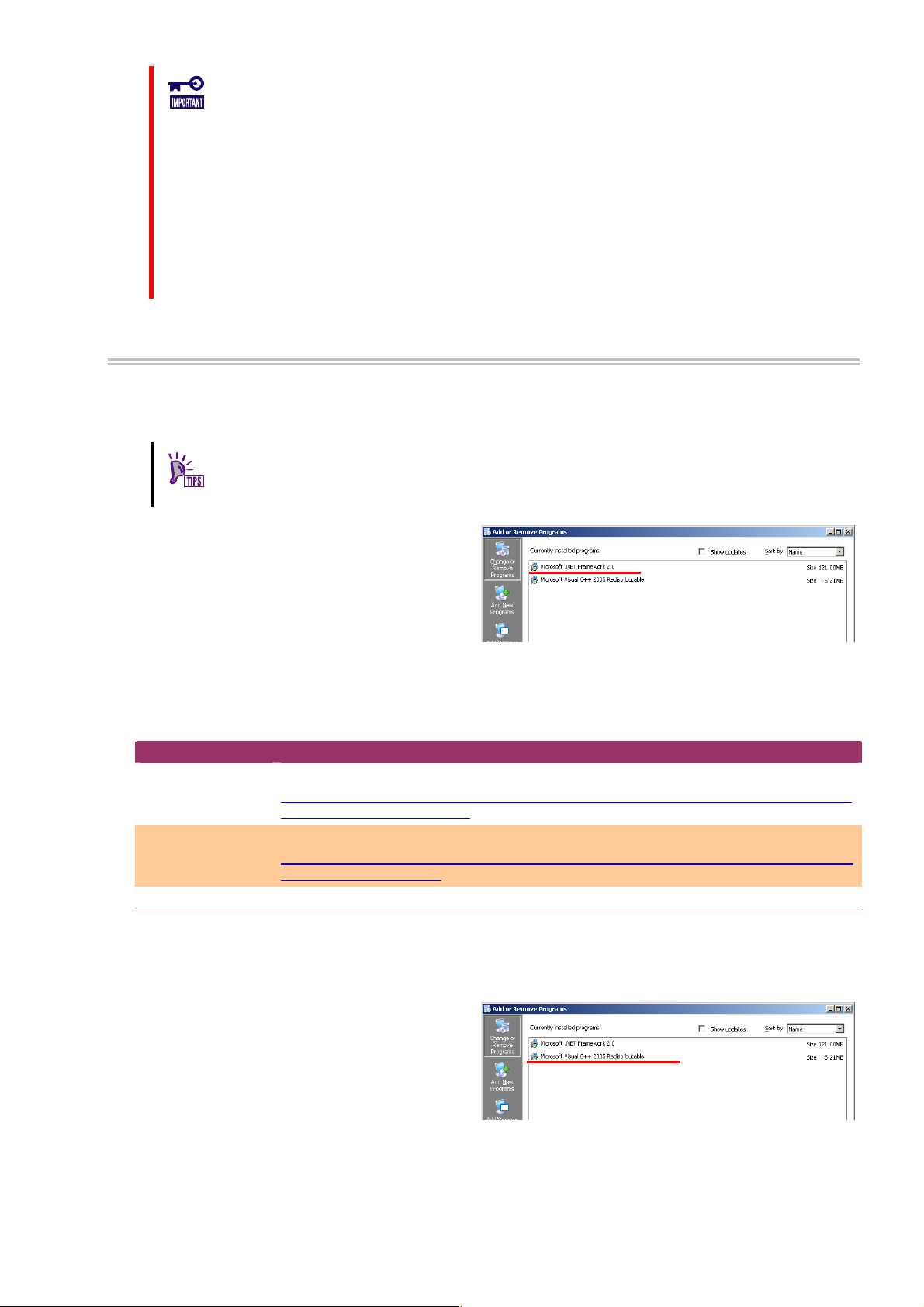
Step 1 Click [Start] - [Control Panel]. Then double-click
[Add or Remove Program].
Step 2 Click [Change or Remove Program] to list
[Currently installed programs]. If the following programs
exist in the list of [Currently installed programs],
Microsoft .NET Framework may not be installed. If the
following packages do not exist, install the package(s).
- [Microsoft .NET Framework 2.0] (for x64, [Microsoft .NET Framework 2.0 (x64)])
Step 3 Microsoft .NET Framework Version 2.0 uses different packages depending on the CPU architecture. See the table
below to download and install the required packages.
CPU architecture Required components and their vendors
x86 [Microsoft .NET Framework Version 2.0 Redistributable Package (x86)]
http://www.microsoft.com/downloads/details.aspx?FamilyID=0856EACB-4362-4B0D-8EDD-A
AB15C5E04F5&displaylang=en
x64 [Microsoft .NET Framework Version 2.0 Redistributable Package (x64)]
http://www.microsoft.com/downloads/details.aspx?familyid=92e0e1ce-8693-4480-84fa-7d85
eef59016&displaylang=en
Also, The Universal RAID Utility uses the runtime component of the Microsoft Visual C++ 2005 SP1 library. If
the runtime component of the Microsoft Visual C++ 2005 SP1 library does not exist in the computer where the
Universal RAID Utility is to be installed, install the runtime component.
Step 1
[Add or Remove Program].
Click [Start] - [Control Panel]. Then double-click
Step 2 Click [Change or Remove Programs] to list
[Currently installed programs]. If the following program
exists in the list of [Currently installed programs], the
runtime component of the Microsoft Visual C++ 2005
SP1 library may not be installed.
If not, install the runtime component of the Microsoft Visual C++ 2005 SP1 library.
- [Microsoft Visual C++ 2005 Redistributable]
Step 3 For the runtime component of the Microsoft Visual C++ 2005 SP1 library, see the table below to download and
install required packages.
16
Page 17
CPU architecture Required component and its vendor
x86/x64 [Microsoft Visual C++ 2005 SP1 Redistributable Package (x86)]
http://www.microsoft.com/downloads/details.aspx?FamilyID=200b2fd9-ae1a-4a14-984d-389
c36f85647&displaylang=en
Use the x86 package whatever the CPU architecture may be.
There is not the description about Windows Server 2008 in "System Requirements" - "Supported
Operating Systems." But if you use Windows Server 2008 as the operating system, you need to
install this package.
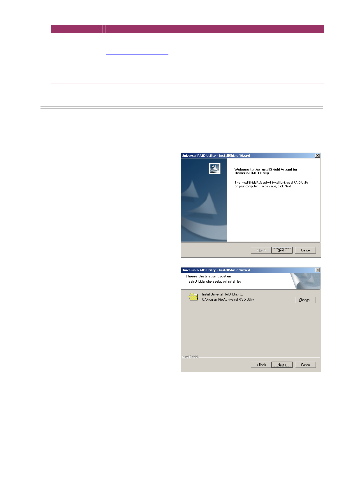
New Installation (Windows)
The Setup Program install Universal RAID Utility newly, when there is not Universal RAID Utility in the computer.
Step 1
Utility and click [Open] in the [Browse] dialog box. Recognize that displays "setup.exe" in [Name] box on [Run] dialog box
and click [OK].
Step 2 The new installation starts the InstallShield
Wizard of the Universal RAID Utility. Click [Next].
Click [Start], [Run…], [Browse...]. Click setup.exe in the folder contained the installation image of Universal RAID
Step 3 The Universal RAID Utility is installed in
\Program Files\Universal RAID Utility (or Program Files
(x86) for x64) in the drive where the OS is started by
default. To change the installation folder, click [Change]
and enter another installation folder. Click [Next] to start
the installation.
17
Page 18
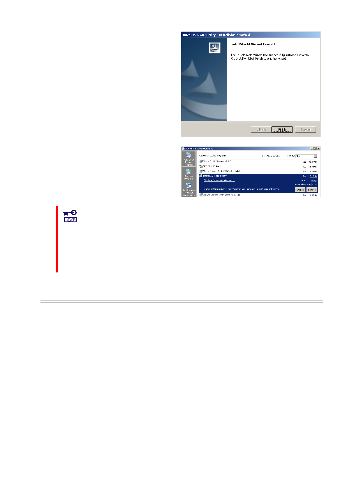
Step 4 At the completion of the installation, the wizard
appears as shown in the figure to the right. Click [Finish].
Step 5 If installation completes, "Universal RAID Utility"
is registered to the program list in the [Change or
Remove Programs].
Also, 1 or several programs to control RAID controller in
your system are registered to the program list.
- LSI SAS Storage SNMP Agent X (X is version)
- WebPAMPRO Agent
Don't uninstall " LSI SAS Storage SNMP Agent X " (X is version) in the list of [Add or
Remove Program]. If you uninstall it, Universal RAID Utility can't use normally.
Please check the setting of [When maximum log size is reached] in the [Properties] of
[System] event log. In case of [When maximum log size is reached] is not [Overwrite
events as needed], when log size reaches maximum size, Universal RAID Utility can not
register the detected RAID event to the Windows event log and alert it to the NEC
ESMPRO Manager. Please set [When maximum log size is reached] to the [Overwrite
events as needed].
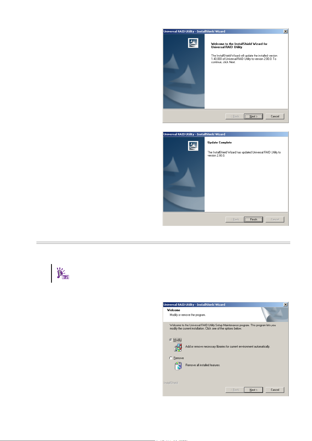
Update Installation (Windows)
The Setup Program install the new version of Universal RAID Utility, when there is the old version of Universal
RAID Utility in the computer. The Setup Program use the following setting continuously.
Installation folder
The contents of RAID log
TCP port using Universal RAID Utility
The running mode of RAID Viewer and raidcmd
The scheduled task of consistency check in task of operating system
Step 1 See "New Installation (Windows)" about the procedure of start the setup program.
18
Page 19
Step 2 The update installation starts the InstallShield
Wizard of the Universal RAID Utility. Click [Next].
Step 3 At the completion of the installation, the wizard
appears as shown in the figure to the right. Click [Finish].
You can check the result of installation by the same way
with "New Installation (Windows)".
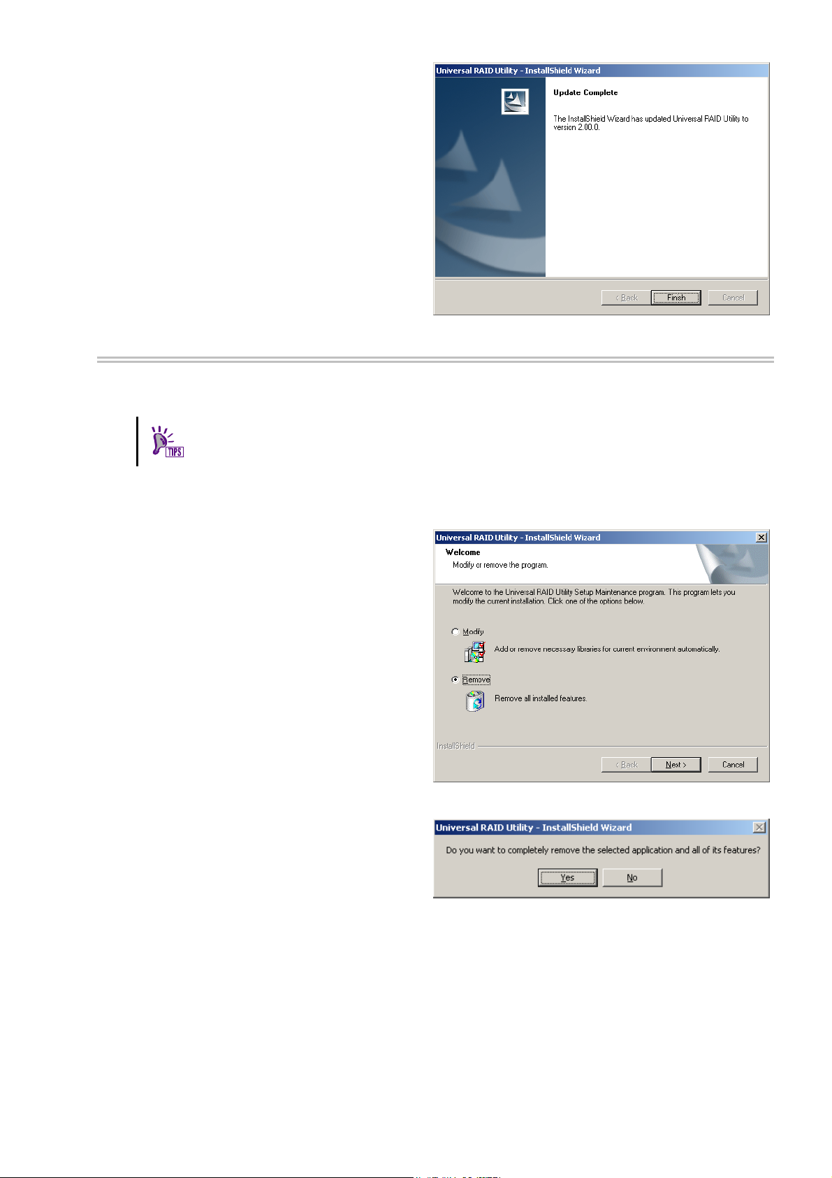
Add Installation (Windows)
The Setup Program install or uninstall the program to control the RAID Controller after added or deleted the
RAID Controller.
You can start the add installation by using the clicking [Modify] on "Universal RAID Utility"
program in the list of [Add or Remove Program].
Step 1
Step 2 The add installation starts the InstallShield
Wizard of the Universal RAID Utility. Select [Modify] and
click [Next].
See "New Installation (Windows)" about the procedure of start the setup program.
19
Page 20
Step 3 At the completion of the installation, the wizard
appears as shown in the figure to the right. Click [Finish].
You can check the result of installation by the same way
with "New Installation (Windows)".
Uninstallation (Windows)
The Setup Program uninstall Universal RAID Utility, when there is the same version of Universal RAID Utility in
the computer.
You can start the uninstallation by using the clicking [Delete] on "Universal RAID Utility"
program in the list of [Add or Remove Program].
Step 1 See "New Installation (Windows)" about the procedure of start the setup program.
Step 2 The uninstallation starts the InstallShield
Wizard of the Universal RAID Utility. Select [Remove]
and clic
k [Next].
Step 3 The InstallShield Wizard of the Universal RAID
Utility is started. Click [Yes] on the dialog box shown to
the right to start the uninstallation. Click [No] to abort
the setup program.
20
Page 21
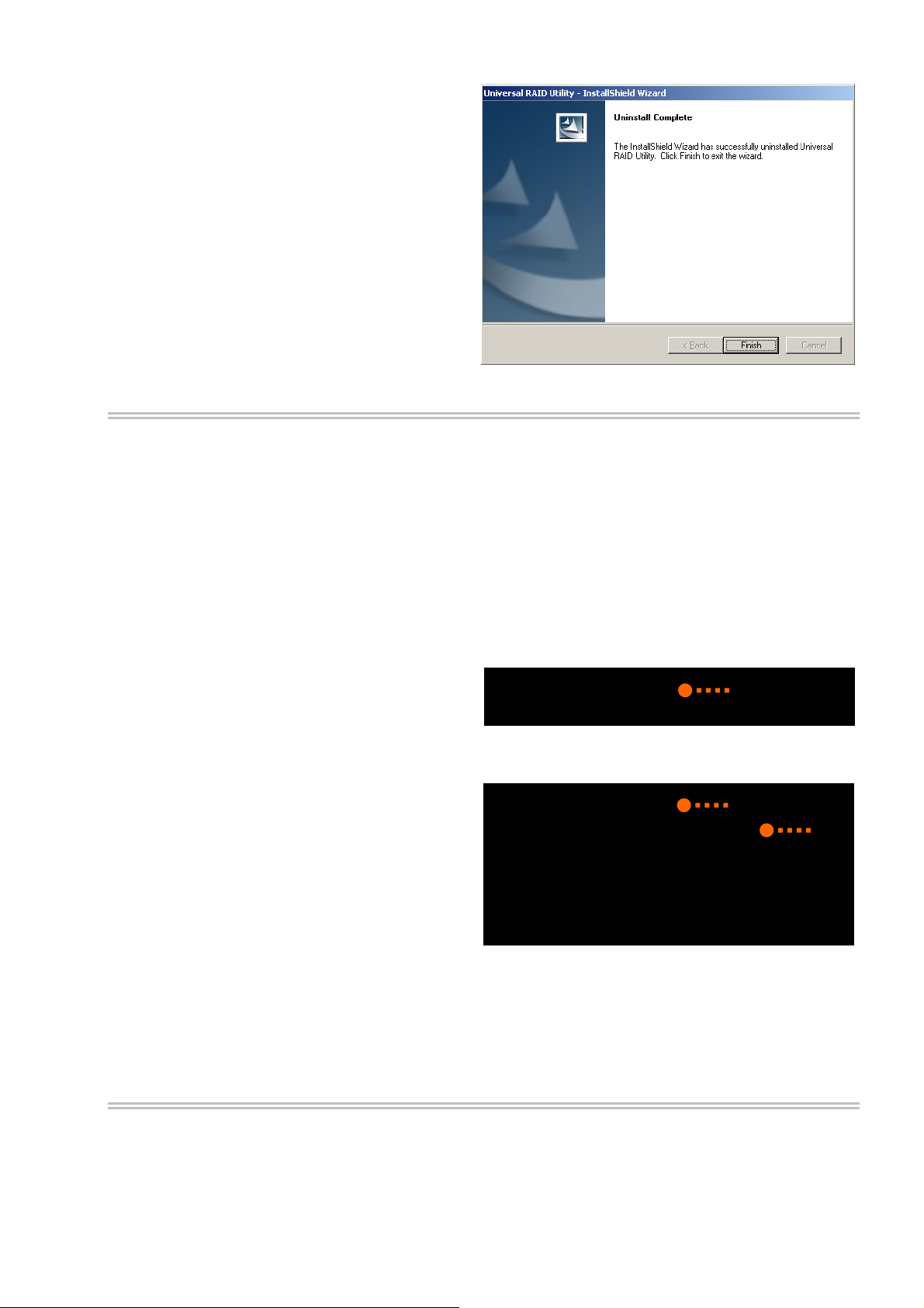
Step 4 At the completion of the uninstallation, the
wizard appears as shown in the figure to the right. Click
[Finish].
If the uninstallation completes, "Universal RAID Utility"
is deleted from the list of [Add or Remove Program]
Also, 1 or several programs to control RAID controller in
your system are deleted too.
.
reparing installation (Linux)
P
You must prepare the following package for using the Universal RAID Utility. If it does not exist in the computer
where the Universal RAID Utility is to be installed.
standard C++ library : libstdc++
GCC 3.3.4 Compatibility standard C
++ library : compat-libstdc++-33
GCC library : libgcc
cron : vixie-cron
oYeu can recognize the ex
istence and install these packages by the following procedure (This procedure is
xample using GCC 3.3.4 Compatibility standard C++ library).
Step 1
GCC 3.
computer or not. If it has existed in your computer, rpm
command displays the right way (the part of "*" is
different by operating system). In this case, refer to "New
your computer, rpm command displays the right wa
You can check by rpm command which does
3.4 Compatibility standard C++ library exist in the
y. In this c it to your computer.
> rpm -q compat-libstdc++-33
compat-libstdc++-33-3.2.3-*
>
tall
ation (Linux, VMware ESX S
Ins erver)". If it has not existed in
ase, install
1
Step 2 Log in to the computer with administrator
author
ity to install Universal RAID Utility.
Insert the install disk of operating system included
"GCC 3.3.4 Comparability standard C++ li
CD-ROM/DVD-ROM drive of your computer.
brary" to
Step 3 Move current directory to the director
3.4 Compatibility standard C++ library, install it
GCC 3.
by rpm command (the part of "*" is different by
operating system).
Step 4 Yo mmand. If the installation finishes, rpm command displays the
below
compat-libstdc++-33-3.2.3-*
(the pa
If the installation fails, rpm co
u can see the result of installation by rpm co
rt of "*" is different by operating system)
mmand does not display this package name.
the
y existed
> rpm -q compat-libstdc++-33
package compat-libstdc++-33 is not installed
> rpm -ivh compat-libstdc++-33 pm
[100%]
1:compat-libstdc++-33 ##############################
[100%]
> rpm -q compat-libstdc++-33
compat-libstdc++-33-3.2.3-*
>
-*.i386.r
2
####Preparing... ################ ##
########
3
New Installation (Linux, VMware ESX Server)
Use setup.sh in the install image for the installation of Universal RAID Utility newly.
21
Page 22

You must install the Universal RAID Utility in the ESX Server. Don't install in the virtual
machine.
Step 1
Change the current directory to the directory in which
the installation image is stored and type as follow
sh setup.sh --install
Step 2 At the end of setup.sh, the installation is
completed. Check the result of the installation by using
the rpm command. When the installation is completed
properly, the following packages is installed:
- UniversalRAIDUtility-1.xx-y (xx is minor version, y is
revision number)
Also, 1 or several packages to control RAID controller
are installe
- storelib-2.aa-0. (aa is minor version)
- WebPAMPRO_Agent-3.aa.bbbb-cc (aa.bbbb-cc is version)
If the installation fails, these packages do not exist in the computer.
Execute setup.sh in the installation image.
d :
s:
> cd
directory name involved install image
> sh setup.sh --install
>
> rpm -q UniversalRaidUtility
UniversalRaidUtility-1.xx-y
>
> rpm -q storelib
storelib-2.aa-0
>
> rpm -q WebPAMPRO_Agent
WebPAMPRO_Agent-3.aa.bbbb-cc
>
Update Installation (Linux, VMware ESX Server)
The Setup Program execute the Update Installation when there is the old version of Universal RAID Utility in the
computer. The Setup Program use the following setting continuously.
1
2
The contents of RAID log
TCP port using Universal RAID Utility
The running mode of raidcmd
The scheduled task of consistency check in crontab of operating system
See "New Installation (Linux, VMware ESX Server)" about the procedure of Update Installation.
Add Installation (Linux, VMware ESX Server)
The Setup Program execute the Add Installation when there is the same version of Universal RAID Utility in the
computer. In add installation, install or uninstall the program to control the RAID Controller after added or
deleted the RAID Controller.
See "New Installation (Linux, VMware ESX Server)" about the procedure of Update Installation.
Uninstallation (Linux, VMware ESX Server)
Use setup.sh in the install image for the uninstallation of Universal RAID Utility.
Step 1
Change the current directory to the directory in which
the installation image is stored and type as follow
sh setup.sh --uninstall
Step 2 At the end of setup.sh, the uninstallation is
completed. Check the result of the uninstallation by
using the rpm command. When the uninstallation is
completed properly, the following package is
uninstalled:
- UniversalRaidUtil
revision number)
Also, 1 or severa
Execute setup.sh in the installation image.
ity-1.xx-y (xx is minor version, y is
l packages to control RAID controller are uninstalled too.
s:
> cd
directory name involved instal age
> sh setup.sh --uninstall
>
> rpm -q UniversalRaidUtility
error: package UniversalRaidUtility is not installed
>
> rpm -q storelib
error: package storelib is not installed
>
> rpm -q WebPAMPRO_Agent
error: package WebPAMPRO_Agent is not installed
>
l im
1
2
22
Page 23

Starting or Stopping Universal RAID Utility
This chapter describes the procedure of starting or stopping each module in the Universal RAID Utility.
raidsrv service
The raidsrv service is started automatically when your computer is booted and stopped automatically when your
computer is shut down.
Without operation of the raidsrv service, the Universal RAID Utility cannot operate normally. Neither make the raidsrv
service be not started nor stop the raidsrv service.
In case of the operating system is Linux or VMware ESX Server, if the raidsrv service
terminates abnormally due to occurrence of an error or a process of the raidsrv service is
terminated forcibly, the lock file for avoiding double starts is left. If the state remains, the
raidsrv service may not be started.
If this occurs, delete the following file before restarting the raidsrv service:
/var/lock/subsys/raidsrv
Starting Universal RAID Utility in Single User Mode
The Universal RAID Utility uses network functions. Accordingly, the Universal RAID Utility cannot be used in the
single user mode of Linux and VMware ESX Server without network functions. To use the Universal RAID Utility
in the single user mode, first enable the network functions in the following procedure and start the raidsrv
service.
Step 1
Step 2 Start the raidsrv service.
Step 3 Check that the raidsrv service is started normally.
If a process ID appears, the raidsrv service is started
normally.
Start the network service.
> /etc/init.d/network start
>
> /etc/init.d/raidsrv start
>
> /etc/init.d/raidsrv status
raidsrv (pid 3738 3718) is running...
>
1
2
3
23
Page 24
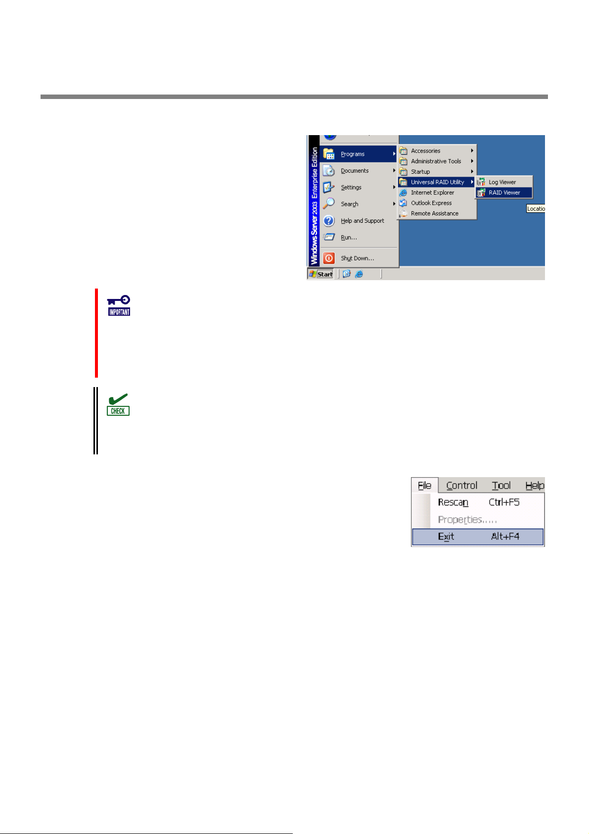
RAID Viewer
Use [Start] menu to open the RAID Viewer.
Click [Start], and point menu in order to [Programs],
[Universal RAID Utility] and [RAID Viewer].
To use the RAID Viewer, you should log on to the computer as a user having the
administrator authority. Only users having the administrator authority can execute the
RAID Viewer.
When start the RAID Viewer on the computer not connected to internet, may wait a few
minutes until startup the RAID Viewer. See "Verification authenticode signature when
startup the RAID Viewer and Log Viewer" for detail.
Only a single RAID Viewer can be started at a time.
The RAID Viewer cannot be started if the raidsrv service does not operate. An error may
occur if the RAID Viewer is started just after the start of the OS. It is because the raidsrv
service has not been started completely. In this case, wait for a while before restarting
the RAID Viewer.
To close the RAID Viewer, select [File] on the Menu Bar of the RAID Viewer and click
[Exit].
24
Page 25
Log Viewer
Use [Start] menu to open the Log Viewer.
Click [Start], and point menu in order to [Programs],
[Universal RAID Utility], [Log Viewer].
Or select [Tool] menu of the RAID Viewer and click [Log Viewer].
To use the Log Viewer, you should log on to the computer as a user having the
administrator authority. Only users having the administrator authority can execute the
Log Viewer.
When start the Log Viewer on the computer not connected to internet, may wait a few
minutes until startup the Log Viewer. See "Verification authenticode signature when
startup the RAID Viewer and Log Viewer" for detail.
Only a single Log Viewer can be started at a time.
To close the Log Viewer, select [File] on the Menu Bar of the Log Viewer and click [Exit].
25
Page 26
raidcmd
raidcmd is command on console as "Command Prompt" in Windows and console(terminal) in Linux and VMware ESX
Server. The raidcmd is executed on a console. Use the raidcmd by the methods described in "Functions of raidcmd".
A user having the administrator authority should run the raidcmd. Only users having the
administrator authority can execute the raidcmd.
In case of the operating system is Windows 2000, you must to restart the Command
Prompt after New/Update installation.
In case of the operating system is Linux or VMware ESX Server, the raidcmd can't start by
existing the lock file after aborted it. If you start the raidcmd when the lock file exists, the
raidcmd displays the following message.
raidcmd:<RU4009> The raidcmd command is already running.
Delete the lock file (/var/lock/subsys/raidcmd), if the raidcmd displays this message
when some processes of the raidcmd don't execute at same time,
In case of the operating system is Windows Server 2008 or Windows Vista, you must use "[Administrator: Command
Prompt]" for running raidcmd. If you use normal Command Prompt, you can not see the message of raidcmd because
of raidcmd runs in the another "[Administrator: Command Prompt]" . You can use "[Administrator: Command
Prompt]" by the following procedure.
Step 1
[Programs], [Accessories], [Command Prompt], click
[Run as administrator] on shortcut menu.
Click [Start] menu, and point menu in order to
Step 2 The operating system may display [User Account
Control] dialog box after clicked [Run as Administrator].
If you want to run the raidcmd, click [Continue].
Step 3 [Administrator: Command Prompt] will start
soon. You should check the window title is
"[ Administrator: Command Prompt]". You can use
raidcmd on [Administrator: Command Prompt].
3
26
Page 27

Standard and Advanced Modes
The RAID Viewer and raidcmd can operate in two running modes, which are Standard Mode and Advanced Modes.
The Standard Mode provides the RAID Viewer and raidcmd with standard management functions for RAID Systems.
The Advanced Mode provides the RAID Viewer and raidcmd with advanced management and maintenance functions
for RAID Systems.
Using the two running modes appropriately depending on users and jobs allows the usability of the RAID Viewer to be
improved and malfunctions to be avoided.
The table below lists the functions of the RAID Viewer and raidcmd available in each mode.
Function RAID Viewer
function
Update display information Rescan NA
See property Property property
Create Logical Drive (simple) Create Logical Drive
(Simple)
Create Logical Drive (custom) Create Logical Drive
(Custom)
Silence Buzzer Silence Buzzer sbuzzer
Consistency Check (start) Consistency Check cc
Consistency Check (stop) [Stop] on Operation
View
Consistency Check (start)
for schedule running
Initialization (start) Initialize init
Initialization (stop) [Stop] on Operation
Delete Logical Drive Delete Logical Drive
Rebuild (start) Rebuild rebuild
Rebuild (stop) [Stop] on Operation
Hot Spare (make) Make Hot Spare hotspare
Hot Spare (remove) Remove Hot Spare hotspare
Change Status of Physical Device (Online) Make Online stspd
Change Status of Physical Device (Failed) Make Offline stspd
Location of Physical Device Locate (Lamp) slotlamp
Easy Configuration Easy Configuration econfig
Start Log Viewer Log Viewer NA
Change running mode Standard Mode
See the version About... in [Help]
See status of operation Operation View oplist
Set option parameters of RAID Controller Property of RAID
Set option parameters of Logical Drive Property of Logical
Functions other than above
NA ccs
View
View
Advanced Mode
menu
Controller
Drive
raidcmd
command
mklds
mkldc
cc
init
delld
rebuild
runmode
run raidcmd without
command
optctrl
optld
Standard
mode
Advanced
mode
27
Page 28

Running Mode when startup RAID Viewer and raidcmd
RAID Viewer
RAID Viewer always starts with Standard Mode. You can change the running mode when RAID Viewer starts.
See "Changing Running Mode at Start of RAID Viewer".
raidcmd
raidcmd starts with Standard Mode at first after installing Universal RAID Utility. If you want to change the
running mode, you must to use "rescan" command (The running mode doesn't change the mode when
restart the computer).
Changing Running Mode
The procedure of changing the running mode is below.
RAID Viewer
Use [Advanced] or [Standard] in [Tool] menu.
See "[Tool] menu" for detail.
raidcmd
Use "runmode" command.
Step 1
Mode to Advanced Mode, run "runmode" command
with -md=a parameter.
Step 2 If you want to change from Advanced
Mode to Standard Mode, run "runmode" command
with -md=s parameter.
If you want to change from Standard
> raidcmd runmode -md=a
Changed running mode to "Advanced M ". ode
>
>
> raidcmd runmode -md=s
Changed running mode to "Standard Mod ".
>
1
2
e
28
Page 29
Functions of RAID Viewer
This chapter describes the functions of the RAID Viewer.
Structure of RAID Viewer
As shown in the figure below, the RAID Viewer is composed of four parts, or Tree View, Operation View, Menu Bar and
Status Bar.
Menu Bar
Tree View
Status Bar
Figure 2 Structure of RAID Viewer
Operation View
Tree View
The Tree View indicates the configuration of RAID Systems managed by the Universal RAID Utility existing in your
computer hierarchically. The Tree View also indicates the types and status of components with relevant icons.
The Tree View displays each RAID System existing in your
computer as a RAID Controller node.
Each RAID Controller node has the node of a battery on
RAID Controller, created all Logical Drives and Disk Array
and connected all Physical Devices. A single node includes
at least a single component of each type.
Every component is accompanied by an icon. The icons
indicate the type and the status of each component
(computer, RAID Controller, Battery, Logical Drive, and
Physical Device) graphically.
29
Page 30
Computer
The first level node shows the computer in which the Universal RAID Utility operates.
The computer icon indicates the status of the RAID Systems existing in the computer totally.
Icon Meaning Description
RAID Controller
Each RAID System on the computer is the RAID Controller node. A RAID Controller node equals a RAID
Controller, and shows the number, ID and model of the RAID Controller.
A RAID Controller icon indicates the status of the RAID system on the RAID Controller totally.
Icon Meaning Description
Computer - Normal All RAID Systems in the computer operate normally. Problems which RAID
Controllers define as failures do not occur.
Computer - Warning One or more RAID Systems of the following status exist in the computer:
"Containing one or more failed components but being operable"
Computer - Fatal One or more RAID Systems of the following status exist in the computer:
"Containing one or more failed components and being inoperable"
RAID Controller - Normal The all of components(battery, Logical Drive, Physical Device) operates
normally on the RAID Controller. Problems which the RAID Controller
detects as failures do not occur.
RAID Controller - Warning
RAID Controller - Fatal One or more components of the following status exist in the RAID
One or more components of the following status exist on the RAID
Controller :
"Containing one or more failed components but being operable"
Controller :
"Containing one or more failed components and being inoperable"
Battery
If the RAID Controller has the battery, the RAID Controller node has a Battery node. A Battery node and icon
shows the status of battery.
Icon Meaning Description
Battery - Normal The battery operates normally.
Battery - Warning The RAID controller detects any problem of the battery.
Disk Array
If there are some Logical Drive in the RAID Controller, the RAID Controller node has the Disk Array nodes
included the Logical Drives. The Disk Array node equals a Disk Array, and shows the number and ID of the Disk
Array. Also, the created some Logical Drives, consisted of all Physical Devices and created some Dedicated Hot
Spares exist in the Disk Array node. A Disk Array icon indicates the status of these totally.
Icon Meaning Description
Disk Array - Normal The created all Logical Drives, consisted of all Physical Devices and created
all Dedicated Hot Spares operates normally. Problems which the RAID
Controller detects as failures do not occur.
Disk Array - Warning These are some components which the status is Warning.
30
Page 31

Logical Drive
The Logical Drive node exists in the Disk Array node. A Logical Drive node equals a Logical Drive, and shows the
number, ID, status and RAID Level of the Logical Drive. A Logical Drive icon indicates the status of the Logical
Drive.
Icon Meaning Description
Disk Array - Fatal These are some components which the status is Fatal or Warning.
Logical Drive - Normal The Logical Drive operates normally.
Logical Drive - Warning Because the Logical Drive contains one or more Physical Devices with
[Status] being [Failed], the redundancy of the Logical Drive is lost or
degraded.
Logical Drive - Fatal Because the Logical Drive contains one or more Physical Devices with
[Status] being [Failed], the Logical Drive is offline and accessing to the
Logical Drive is disabled.
A Logical Drive is created by two or more Disk Arrays according to the kind of the RAID
Controller. In this case, there are the nodes of a Logical Drive exist in two of more the nodes
of Disk Arrays.
Physical Device
The Physical Device node exists in either the Disk Array node or the RAID Controller node. The Physical Device
which has created the Logical Drive and created Dedicated Hot Spare exists in the Disk Array node. The other
Physical Device exists in RAID Controller node. The Physical Device node equals a Physical Device, and shows
the number, ID, status and device type of the Physical Device.
A Physical Device icon indicates the device type and the status of the Physical Device.
Icon Meaning Description
Physical Device - Ready The Physical Device is not used to create a Logical Drive yet.
Physical Device - Online The Physical Device is already used to create a Logical Drive.
Problems which the RAID Controller detects as failures do not occur.
Physical Device - Hot Spare The Physical Device is registered as a Hot Spare.
Physical Device - Rebuilding The Physical Device which is rebuilding now.
Physical Device - Warning The Physical Device which detects one or more S.M.A.R.T. errors.
Physical De atal oller.
CD Drive/DVD Drive The Physical Device which device type is [CD/DVD].
vice - F The Physical Device which is detected a failure by RAID Contr
Tape Drive The Physical Device which device type is [Tape Drive]
.
The nodes of Dedicated Hot Spare created to two or more Disk Arrays existed in each node
of Disk Array.
Shortcut Menu
Right-clicking the node of RAID Controller, Disk Array, Logical Drive, Physical Device and Battery allows the
shortcut menu to appear. On the shortcut menu, you ca
o
peration. See "Menu Bar" for detail of each function.
n display the property and execute the something
31
Page 32

Operation View
The Operation View indicates the status and results of operations executed in the computer after the RAID Viewer is
started.
Figure 3 Operation View
The following operations may appear on the Operation View. For each operation, the target component and the status
of the operation appear.
Initialize
Rebuild
Consistency Check
Operations being executed while the RAID Viewer is started and those started after the RAID Viewer is started are
listed.
You can see the status and result of operations by the value of [Status].
Status Description
Running (N %) The operation is be running (N is progress).
Completed The operation completed.
Failed The operation failed.
Stopped The operation stopped (by [Stop]).
Paused (N %) The operation is paused (N is progress).
Queued The operation is queued.
Stop Processing The operation is processing [Stop].
Terminated operations continue to appear until the RAID Viewer is closed. However, the terminated operations will not
appear at the next start of the RAID Viewer.
To delete an operation terminated while the RAID Viewer
is started, click the operation to be deleted and [Delete]
.
An operation being executed can be stopped on the way.
To do this, click the operation to be stopped and [Stop].
Operations allowed to be stopped vary depending on running modes. See "Standard and
Advanced Modes" for details.
32
Page 33

Menu Bar
The RAID Viewer has four menu items on the Menu Bar, or [File], [Control], [Tool] and [Help].
Figure 4 Menu of RAID Viewer
The following describes the menu items.
With the running mode of the RAID Viewer being "Standard", the functions unavailable in
the Standard Mode do not appear on the pull-down menus of the menu items.
Depending on the type or status of the target component selected on the Tree View,
some menu items cannot be executed. If so, clicking such a menu item is disabled.
[File] menu
[File] menu includes items for updating the display information on the RAID Viewer, displaying the property of
each component, and terminating the RAID Viewer.
Menu item Description
[Rescan] The Universal RAID Utility acquires the configuration and state information from all of RAID
system again, and updates the management information by them. The RAID Viewer displays
the newest information.
[Properties...] Indicates the property of the component selected on the Tree View (RAID Controller, Logical
Drive or Physical Device).
[Exit] Closes the RAID Viewer.
[Control] menu
[Control] menu includes items for operating RAID Controllers, Logical Drives, and Physical Devices. To use a
function subordinate to [Control] menu, first click the target component on the Tree View and select the menu
item to be executed from the pull-down menu.
Some functions of [Control] menu may be disabled depending on the type or status of the selected component.
(The figure shown to the right shows a sample pull-down menu of [Control] menu displayed by clicking a RAID
Controller on the Tree View and selecting [Control] while the RAID Viewer is executed in the Advanced Mode.)
If the running mode of the RAID Viewer is set to the Standard Mode, the functions restricted in the Standard
Mode are disabled. See "Standard and Advanced Modes" for the functions available depending on running
modes.
Functions executable by RAID Controller
Menu item Description
[Create Logical Drive] Creates a Logical Drive in the selected RAID Controller.
[Create Logical Drive] has two modes, [Simple] and [Custom].
In the [Simple] mode, a Logical Drive can be simply created only by selecting a RAID
Level and Physical Devices.
In the [Custom] mode, a Logical Drive can be created by specifying detailed settings.
[Silence Buzzer] Stops the Buzzer in the RAID Controller.
33
Page 34

Functions executable for Logical Drive
Menu item Description
[Consistency Check] Executes Consistency Check for the selected Logical Drive.
[Initialize] Initializes the selected Logical Drive.
[Initialize] has two modes, [Full] and [Quick].
In the [Full] mode, initializes the entire area of a Logical Drive.
In the [Quick] mode, initializes only several leading blocks including the information on
managing a Logical Drive.
[Delete Logical Drive] Deletes the selected Logical Drive.
Functions executable for Physical Device
Menu item Description
[Rebuild] Rebuilds the selected Physical Device.
[Hot Spare] Makes a Hot Spare with the selected Physical Device or removes a Hot Spare.
[Make Global Hot Spare] makes Physical Devices be Global Hot Spares available as
Hot Spares of all Logical Drives in the relevant RAID System.
[Make Dedicated Hot Spare] makes Physical Devices be Dedicated Hot Spares
available as Hot Spares of specific Logical Drives.
[Remove Hot Spare] removes Physical Devices from Hot Spares.
[Make Online] Sets the status of the selected Physical Device to online.
[Make Offline] Sets the status of the selected Physical Device to offline.
[Locate(Lamp)] Goes on (or blinks) the lamp on the slot where the selected Logical Drive is installed.
[ON] goes on the lamp.
[OFF] goes off the lamp.
[Tool] menu
[Tool] menu includes tools used to manage RAID Systems and items for changing the operation of the RAID
Viewer.
[Easy Configuration...] Executes Easy Configuration allowing a RAID System to be configured easily.
[Log Viewer] Starts the Log Viewer.
[Advanced Mode] or
[Standard Mode]
[Option...] Allows you to provide settings for the Universal RAID Utility.
[Help] menu
[Help] menu includes the item of indicating the version and revision of the Universal RAID Utility and the
version of the RAID Viewer.
[About...] Indicates the version and revision of the Universal RAID Utility and the version of the RAID
Menu item Description
Alters the running mode. The item varies depending on the running mode.
[Advanced Mode] sets the running mode to the Advanced Mode.
[Standard Mode] sets the running mode to the Standard Mode.
Menu item Description
Viewer.
34
Page 35

Status Bar
The Status Bar indicates the current running mode of the RAID Viewer.
Figure 5 Status Bar of RAID Viewer
35
Page 36

r
Functions of Log Viewer
This chapter describes the functions of the Log Viewer.
Structure of Log Viewer
As shown in the figure below, the Log Viewer is composed of three parts, or Log View, Menu Bar and Status Bar.
Menu Bar
Status Ba
Figure 6 Structure of Log Viewer
The Status Bar is used only for changing the size of the Log Viewer window.
Log View
36
Page 37

Log View
The Log View indicates RAID System operation logs logged by the raidsrv service.
You can view the following information on the Log View.
Item Description
Type Logs are classified into three types as follows:
Fatal: A log of the type is registered when a fatal error occurs.
Warning: A log of the type is registered when a problem occurs which is not fatal but requires your
attention.
Information: A log of the type is registered at occurrence of an event such as execution of an
operation without any problem.
Date Indicates the date on which the event occurred.
Time Indicates the time at which the event occurred in the 24-hour format.
Event ID Indicates the event ID of the log.
Description Indicates the contents of the log.
Double-clicking an arbitrary log allows the detailed
information on the log to be displayed.
Menu Bar
The Log Viewer has two menu items, or [File] and [Help] on the Menu Bar.
Figure 7 Menu of Log Viewer
The following describes each menu item.
[File] menu
[File] menu includes items for updating the display information on the Log Viewer and terminating the Log
Viewer.
37 38
Page 38

Menu item Description
[Refresh] Reads the contents in the RAID Log and updates the Log View to the latest.
[Properties...] Opens the [Event Properties] dialog box and displays the detailed information on the log
selected by the Log Viewer.
[Exit] Closes the Log Viewer.
[Help] menu
[Help] menu includes the item of indicating the version of the Log Viewer.
Menu item Description
[About...] Indicates the version of the Log Viewer.
Page 39

Functions of raidcmd
This chapter describes the functions of the raidcmd.
Command Line
To use the raidcmd, specify a command and one or more
parameters for the command if necessary.
To use the raidcmd, you should log in to the computer as a user having the administrator
authority. Only users having the administrator authority can execute the raidcmd.
Executing the raidcmd without any command and its parameters indicates the version of
the raidcmd.
> raidcmd command <parameters of command>
Returned Value from raidcmd
The returned value of the raidcmd is the result of executing the command.
Returned value Execution result
0 Normal termination of command
1 Abnormal termination of command
Error Messages of raidcmd
When a command o
the relevant error message appears in the following
format:
f the raidcmd terminates abnormally,
> raidcmd (command) (parameters of command)
raidcmd : error message
>
Commands of raidcmd
See "raidcmd Command Reference" for commands of the raidcmd.
Use help command, displays the help of raidcmd.
Termination of raidcmd
In case of the operating system is Windows, raidcmd is the batch file in system folder (the batch file in system folder
call raidcmd binary in the installed folder of Universal RAID Utility). Therefore, if you terminates raidcmd by CTRL + C
key, the operating system displays the message as "Terminate batch job (Y/N)?". When displays this message,
raidcmd binary is terminated already.
39
Page 40

Referring to Information on RAID System
This chapter describes how to see the configurations and status of RAID Systems and the RAID System operation log.
Referring to Property of RAID Controller
For the information on a RAID Controller, see the property of the RAID Controller.
To display the property of RAID Controller by RAID Viewer,
click the RAID Controller whose information is to be seen
on the Tree View and click [Properties] on the pull-down
menu of menu item [File].
The [RAID Controller Properties] dialog box has the
[General] and [Option] tabs.
The [General] tab indicates the property of the RAID
Controller.
The [Option] tab allows you to see the settings of the RAID
Controller.
You can change the settings in the Advanced Mode.
Use "
property" command to see the property of a RAID
Controller by raidcmd.
Item
RAID Viewer
Number RAID Controller #X Indicates the management number (logical address) of the RAID Controller in
ID ID Indicates the original identification value of the RAID Controller. The BIOS utility
Vendor Vendor Indicates the vendor of the RAID Controller.
Model Model Indicates the model name of the RAID Controller.
Firmware Version Firmware Version Indicates the version of the RAID Controller.
Cache Size Cache Size Indicates the size of cache on RAID Controller in MB.
Item
raidcmd
the Universal RAID Utility.
The Universal RAID Utility assigns a number beginning with 1 for each RAID
Controller.
of the RAID Controller uses the address of the identification value.
> raidcmd property -tg=rc -c=1
RAID Controller #1
ID : 0
Vendor : LSI Corporation
Model : MegaRAID SAS PCI Express(TM)
ROMB
Firmware Version : 1.12.02-0342
Cache Size : 128MB
Battery Status : Normal
Rebuild Priority : High
Consistency Check Priority : Low
Patrol Read : Enable
Patrol Read Priority : Low
Buzzer Setting : Enable
>
Description
40
Page 41

Item
RAID Viewer
- Battery Status Indicates the status of the battery installed in the RAID Controller.
Initialize Priority Initialize Priority Indicates the priority level of Initialize executed in the computer system.
Rebuild Priority Rebuild Priority Indicates the
Consistency Check
Priority
Patrol Read Patrol Read Indicates whether Patrol Read is executed or not.
Patrol Read Priority Patrol Read Priority Indicates the priority level of Patrol Read executed in the computer system.
Buzzer Setting
Consistency Check Indicates the priority level of Consistency Check executed in the computer
Priority system.
Buzzer Setting Indicates whether is used if a failure occurs in
Some types of the RAID Controller do not roperties of RAID
Controllers and/or items whose settings s indicate
space or do not appear in the list.
Item Description
raidcmd
Three possible status are as follows:
Normal: Indicates that the battery can be used normally。
Warning: Indicates that the battery cannot be used normally due to some
reason.
Not Present: Indicates that no battery is installed in the RAID Controller.
This item is indicated by raidcmd only. You need to see
for seeing the information of battery by RAID Viewer.
Three possible Initialize Priorities are as follows:
High: Executes Initialize at high priority.
Middle: Executes Initialize at balanced priority.
Low: Executes
Three possi
High: E
Middle
Low: Executes Rebuild at low priority.
Three possible Consistency Check Priorities are as follows:
High: Executes Consistency Check at high priority.
Middle: Executes Consistency Check at balanced priority.
Low: Executes Consistency Check at low priority.
Enable: Executes Patrol Read.
Disable: Does not execute Patrol Read.
Three possible Patrol Read Priorities are as follows:
High: Executes Patrol Read at high priority.
Middle: Executes Patrol Read at balanced priority.
Low: Execu
the RAID System.
Enable: Uses the B
Disable: Does not
Initialize at low priority.
priority level of Rebuild executed in the computer system.
ble Rebuild Priorities are as follows:
xecutes Rebuild at high priority.
: Executes Rebuild at balanced priority.
tes Patr
ol Read at low priority.
the Buzzer of the RAID Controller
uzzer.
use the Buzzer.
support items appearing in the p
can be changed. Unsupported item
the property of Battery
Referring to Property of Battery
For the information on a Battery on RAID Cont f the Battery by RAID Viewer and, see the
property of the RAID Controller by raidcmd.
To disp the property of Battery by RAID View
lay
Battery e information o be seen on the
click [Pr ies] on the pu f menu
The [G tab indicate ty of the
whos
opert
eneral]
ll-down menu o
s the proper
roller, see the property o
er, click the
Tree View and is t
item [File].
Battery.
41
Page 42

Item Description
RAID Viewer
Status Indicates the status o troller.
Three possible status
Normal: Indicates tha
Warning: Indicates that the batt
Not Present: Indicates
f the battery installed in the RAID Con
are as follows:
t the battery can be used normally。
ery cannot be used normally due to some reason.
that no battery is installed in the RAID Controller.
Ref to rterring Prope y of Logical Drive
For the information on a Logical Drive, see the
property of the Logical Drive.
To disp y of RAID
lay the propert Logical Drive by Viewer,
click the Logical Drive whose information is to
the Tree View and click [Properties] on the pul
be seen on
l-down menu
of menu item [File].
The [L t ta
ogical Drive Proper
[Gene [Option] tab
ral] and
ies] dialog box con
s.
ins the
The [General] tab indicates the property of the
Logical Drive.
The [Option] tab allows you to see the settings
Logica
l Drive.
You can g M
change the settin s in the Advanced ode.
of the
Use "
pr ty of a Lo
Drive b
operty" command t
y raidcmd.
o see the proper gical
> raidcmd property -tg=ld -c=1 -l=1
RAID Controller #1 Logical Drive #1
ID : 0
l Device Number : 1, 2, 3
Physica
Disk Array Informat
RAID Level
Capacity : 20GB
Stripe Size : 64KB
Cache Mode (Current) : Write Back
Cache Mode (Setting) : Auto Switch
Status : Online
>
ion : 1 (order 1/1)
: RAID 5
Item
RAID Viewer
Number RAID Controller #X Indicates the management num
Logical Drive #Y
ID ID Indicates the original identification value of the Logical Drive. Use this value to
Physical Device
Number
Physical Device
Number
Item
raidcmd
Description
ber (logical address) of the Logical Drive in the
Universal RAID Utility.
The Universal RAID Utility assigns a number beginning with 1 in
correspondence with the value of [ID].
create Logical Drives managed by the BIOS utility of the RAID Controller
correspond with th
Indicates the number
the Logica
l Drive exists.
ose managed by the Universal RAID Utility.
s of Physical Devices configuring the Disk Array in which
42
Page 43

Item
RAID Viewer
Disk Array
Informa
RAID Level RAID Level Indicates the RAID Level of the Logical Drive.
Capacity Capacity Indicates the capacity of the Logical Drive in GB.
Stripe Size Stripe Size Indicates the
Cache Mode Cache Mode Indicates the current value of the mode of writing data to the cache memory
(Current) (Current) installed in the RAID Controller.
Cache Mode
(Setting)
Status Status Indicates the status of the Logical Drive.
tion Information information on the location in the Disk Array. The information is displayed in
Disk Array Indicates the number of the Disk Array in which the Logical Drive exists and the
Cache Mode
(Setting)
Each RAID Controller supports specific rted items
indicate space or do not appear in the
Item Description
raidcmd
the following format.
<RAID Viewer>
Disk Array number (sequence number starting from the top / sequence number
of Logical Drive in Disk Array)
<raidcmd>
Disk Array number (order sequence number starting from the top / sequence
number of Logical Drive in Disk Array)
The value can be RAID 0, RAID 1, RAID 5, RAID 6, RAID 00, RAID 10, RAID 1E,
RAID 50 or RAID 60.
Stripe Size of the Logical Drive.
The value can b
512KB, or 102
Three possible modes are as follows:
Write Back: Writes data to the cache memory asynchronously.
Write Through: Writes data to the cache memory synchronously.
Indicates the mode of writing data to the cache memory installed in the RAID
Controller.
Three possible modes are as follows:
Auto Switch: Switches the mode automatically between Write Back and Write
Through
Write Back: Writes data to the cache memory asynchronously.
Write Thr
Three possible status are as follows:
Online: Indicates that the redundancy of the Logical Drive is retained.
Degraded: Indicat rive is lost or es that the redundancy of the Logical D
degraded. Accessing to the Logical Drive is enabled.
Offline: Indicates t ssing to the Logical hat the Logical Drive is offline and acce
Drive is disabled.
e 1KB, 2KB, 4KB, 8KB, 16KB, 32KB, 64KB, 128KB, 256KB,
4KB.
depending on the existence and/or status of battery.
ough: Writes data to the cache memory synchronously.
RAID Levels and Stripe Sizes. Unsuppo
list.
Each RAID Controller supports specific Cache Modes. Unsupported Cache Modes do not
appear.
Each RA oller supports specific items appearing on the Property tab of the
Logical d specific items whose settings can be changed. Unsupported items
in n
ID Contr
Drive an
dicate space or do ot appear in the list.
The status of a Logical D ID Level and the number of
Physical Devices failed.
If the RAID Level is RAID l
be [Degraded] or [Offlin
rive is defined depending on the RA
10 or RAID 50 and two Physical Devices are failed, the status wil
e] depending on the failed Physical Devices.
43
Page 44

Number of failed Physical
Devices
RA OID 0 nline Offline Offline Offline
RAID 5 Online Degraded Offline Offline
RAID 10 O Degraded Degraded/Offline Offline nline
RAID 50 O
0 1 2 3 or more
nline DegrRAID 1 O aded Offline -
nline Degraded RAID 6 O Degraded Offline
nline Degraded Degraded/Offline Offline
Referring to Property of Physical Device
For the information on a Physical Device, see t hysical Device.
he property of the P
To displa operty of P vice by R
click the Physical Device whose information is
the Tree View and click [Properties] on the pul
menu it
The [G dicate of the
Device
y the pr hysical De AID Viewer,
to be seen on
l-down menu of
em [File].
eneral] tab in
s the property Physical
.
Use "
p ty" command t see the property of a physical
roper o
drive by raidcmd.
> raidcmd property -tg=pd -c=1 -p=1
RAID Controller #1 Physical Device #1
ID : 0
Enclosure : 1
: 1
Slot
Type : HDD
Device
Interface : SAS
Vendor/Model : SEAGATE ST936751SS
Firmware Version : 0001
Serial Number : 3PE073VM
Capacity : 33GB
Status : Online
.R.T. : Normal
S.M.A
>
Item
RAID Viewer
Number
ID ID Indicates the original identification value of the Physical Device. Use this value
RAID Controller #X Indicates the management number (logical address) of the Physical Device
Physical Device #Y
Item
raidcmd
Description
the Universal RAID Utility.
The Universal RAID Utility arranges Physical Devices in the ascending order of
IDs and assigns a number beginning with 1 sequentially to the Physical
Devices.
to make Physical Devices managed by the BIOS utility of the RAID Controller
correspond with those managed by the Universal RAID Utility.
The format of the ID varies depending on the types of RAID Controllers.
in
44
Page 45

Item
RAID Viewer
Enclosure Indicates the number of Enclosure inserted Physical Device.
Device Type ce Type es the typ l Device.
Interface Interface Indicates the type of the interface to which the Physical Device is connected.
Vendor/Model Vendor/Model Indicates the vendor and model name of the Physical Device.
Firmware Version Firmware Version Indicates the version of the Physical Device.
Serial Number Serial Number Indicates the serial number of the Physical Device.
Capacity Capacity Indicates the capacity of the Physical Device in GB.
Status Status Indicates the status
Hot Spare Hot Spare Indicates the Hot Spare mode of the Physical Device if it is specified as a Hot
Information Information Spare. Two possible modes are as follows:
S.M.A.R.T. S.M.A.R.T. Indicates the diag d
Enclosure
Slot IndicatSlot es the num nserted Physiber of Slot i cal Device.
Devi Indicat e of Physica
Each RA oller supports specific items appearing on the Property tab of the
Physica pecific items whose settings can be changed. Unsupported items
indicate t appear in the list.
E ic hen you execute Make Offline, [Status]
ven if Physical Dev
it Fa
em is changed to [
Item Description
raidcmd
lue is a num inning with 1.
This va ber beg
This value is a nu ning with 1.
Four po es are as fo
ssible typ llows:
HDD : H Drive
ard Disk
HDD(SSD) : Solid State Drive
Ta e Dri ve : Tap e Dr iv
p e
CD/DVD : CD drive or DVD drive
Two possible types are as follows:
SAS : Serial Attached SCSI
SATA : Serial ATA
This item is indicat
Five possible status are as follows:
Online: Indicates that the Physical Device is incorporated into a Logical Drive to
operate normally.
Failed: Indicates that the Physical Device is incorporated into a Logical Drive
but is failed.
Rebuilding: Indicates that the Physical Device is rebuilding.
Hot Spare: Indicates that the Physical Device is set as a Hot Spare.
Ready: Indicates that the Physical Device is not incorporated into a Logical
Drive.
This item is indicated when [Device Type] item is [HDD] or [HDD(SSD)].
Global: The Physic f any Disk Array in the al Device can be used as a Hot Spare o
RAID Controller.
Dedicated: The Ph t Spare of the specified ysical Device can be used as a Ho
Disk Array. Also in Disk Array. dicates the number of the specified
This item is indicat ] or [HDD(SSD)].
Reporting Technol as follows.
Normal: Does not .R.T. function.
Detected: Detects A.R.T. function.
This item is indicat when [Device Type] item is [HDD] or [HDD(SSD)].
mber begin
dicated when [Device Type] item is [HDD] or [HDD(SSD)]. This item is in
ed when [Device Type] item is [HDD] or [HDD(SSD)].
of the Physical Device.
ed when [Device Type] item is [HDD
nosis result of S.M.A.R.T.(Self-Monitoring, Analysis an
ogy) function. Two possible statuses are
detect any error caused by the S.M.A
one or more errors caused by the S.M.
ed
ID Contr
l Device and s
space or do no
e does not break down w
iled].
Referring to Property of Disk Array
For the on on a D informati isk Array, see the property of the Disk Array.
45
Page 46

To display the property of Disk Array by RAID Viewer, click the
Disk A hose information is to be seen on
rray w
and cli roperties] on th l-down menu of m
ck [P
e pul enu item
the Tree View
[File].
The [G ndicate ty of the
eneral] tab i s the proper Disk Array.
Use "p ommand property o
Array b
roperty" c
y raidcmd.
to see the f a Disk
> raidcmd property -tg=da -c=1 -a=1
RAID Controller #1 Disk Array #1
ID : 0
Physical
Capacity : 67GB
Unused Capacity : 47GB
>
Device Number : 1, 2, 3
Item Item
RAID Viewer raidcmd
Number RAID Controller #X
Disk Array #Y
ID ID Indicates the original identification value of the Disk Array. Use this value to
Physical Device
Number
Capacity Capacity Indicates the total capacity of Physical Device in Disk Array i
Unused Capacity Unused Capacity
Number
Indicates the management number (logical address) of the Disk Array in the
Universal RAID Utility.
create Disk Array managed by the BIOS utility of the RAID Controller
correspond with those managed by the Universal RAID Utility.
Indicates the numbers of Physical Devices configuring the Disk Array. Physical Device
Indicates the total capacity of unused area in the Disk Array in GB.
Description
n GB.
Che g Ex ion ckin ecut Status of Operation
RAID Viewer and raidcmd allows the checking s of operation in the RAID System.
To check the execution status of operation by tion View"
for detail.
ck the exe tus of oper raidcmd, use
To che cution sta ation by
"oplist" command. The following operations are displa
by "oplist" command. The target components
appear in operations:
Initialize
Rebuil
Consistency Ch
The operation sults of
terminated op
d
eck
performed at execution of the raidcmd appears. Terminated operations do not appear. For the re
erations, see the RAID Log and/or properties.
Physical Device has two numbers on oplist.
Physical Device #M(N)
M : The number of Physical Device
N : ID of Physical Device
execution statu
RAID Viewer, use Operation View on RAID Viewer. See "Opera
> raidcmd oplist
yed
and status
RAID Controller #1
Logical Drive #1 : Consistency Check (52%)
Logical Drive #2 : Initialize (33%)
Physical Device #1(0): Rebuild (99%)
RAID Controller #2
Logical Drive #1 : Consistency Check (2%)
Physical Device #2(1): Rebuild (22%)
>
46
Page 47

Updating Information of RAID System
The management information of RAID System managed by t
service at the following timings:
Starting raidsrv service
Receiving an event such as change of RAID System status or change of execution status of an operation having
occurred
o update the management information of the RAID system to the latest, collect the newest information of all RAID
T
System by the RAID Viewer and raidcmd.
he Universal RAID Utility is corrected by the raidsrv
RAID Viewer
Use [Rescan] in [File] menu.
Step 1
acquires the information on the RAID System from the RAID System again and
up he manageme o the latest.
dates t
aidcmd
r
Use "rescan" command.
Step
service the inform RAID System
from the RAID Syst
managemen
Start the RAID Viewer. Click [Rescan] in [File] menu. The raidsrv service
nt information t
1
Exec n" command. The raidsrv
ute "resca
acquires ation on the
em again and updat
ormation to the la
t inf test
es the
.
> raidcmd rescan
>
1
Referring to RAID System Operation Log
Operations done for RAID Systems and events occurred in the RAID Systems are registered to the RAID Log of the
Universal RAID Utility. See "Logging Events to RAID Log" for detail.
case of the operating system is Windows, use Log Viewer to refer to RAID Log
In
The information saved in the RAID Log at the start of the Lo
update the information, click [Refresh] on the pull-down m
Log Viewer acquires th
latest.
In case of the operating sy
e RAID Log again and updates the displa
stem is Linux, use text editor or otherwise to refer to RAID Log.
g V To
iewer appears on it.
enu
of menu item [File]. The
yed information to the
47
Page 48

g
g
Configuration of RAID System
This chapter describes the config
The Universal RAID
Utility provides a variety of functions depending on purposes.
Would like to
make
Hot Spare as
measures against
failure of Physical
Device.
Would like to
configure
System e
RAID
asily due to
no expert knowledge
of RAID System.
uration of a RAID System by using the Universal RAID Utility.
Allows Global or Dedicated
Hot Spare to be made
without errors
.
See "Makin
See "Confi
System Easily".
Provides "Easy Configuration"
allowing RAID System to be
configured witho
knowledge of RAI
ut expert
D System.
Hot Spare".
uring RAID
Would like to add a
Logical Drive easily.
Would like to specify
configuration of
Logical Drive closely
or create more than
one Logical Drive at a
time.
Would like to delete
unnecessary Logical
Drive. However, it is
anxious about
destruction of system
by mistak
e.
Allows Logical Drive to be
made only by setting two
selection items.
Allows information on
Logical Drive to be set
closely or more than one
Logical Drive to be created
at a time at will.
Disables Logical Drive
containing partition to be
deleted by mistake.
See "Creating Logical
Drive Easily".
See "Cre
Drive Fre
ating Logical
ely".
See "Deleting Logical
Drive".
Figure 8 RAID System configuration functions
48
Page 49

Making Hot Spare
The Universal RAID Utility can make a Hot Spare to be replaced with a Physical Device in whic
h a failure occurs.
Hot spares can have the following two modes.
Mode Description
Global (Hot Spare) Available as a Hot Spare of every Disk Array for a single RAID Controller.
Dedicat a Hot Spare of a specific Disk Array for a single RAID Controller. ed (Hot Spare) Available as
In either mo to have a Hot Spare operate normally.
A Hot ly for a Disk Array configured with P terface
A Hot Spare can operate properly only i e capacity equal to or larger than that of the
de, note the following
Spare can operate properly on
nd the sa
type a me device type.
Physical Device in which a failure occur
hysical Devices of the same in
f the Hot Spare has th
s.
A Physical Device in which a S.M.A.R.T. error is detected cannot be used as a Hot Spare.
About Global Hot Spare
Glob e of ev RAID Controller.
al Hot Spare is a Hot Spar
Ex.1 : bal Hot Spa hich has Logical Drive #1 and #2, the Global
If you make the Glo
Hot Spare is a Hot Spare of Logical
ery Logical Drives for a single
re on the RAID Controller w
Drive #1 and #2.
Logical Drive
#1
Logical Drive
#2
Global Hot
Spare
Figure 9 Global Hot Spare 1
Ex.2 l Drive #3 on the RAID System of Ex.1, the is a Hot Spare for the
: If you create the Logica
Lo
gical Drive #3 too.
Global Hot Spare
Logical Drive
#1
Log
ical Drive
#2
Logical Drive
#3
Global Hot
Spare
Figure 10 Global Hot Spare 2
49
Page 50

t Spare About Dedicated Ho
Dedicated Hot Spare is a Hot Spare of specified Logical Drives for a single RAID Controller. The Dedicated Hot
Spare features the following:
Dedicated Hot Spare is a Hot Spare of specified Lo
O icated Hot Spare can be a Hot Spare of one or l Drives.
ne Ded more Logica
One or m cated Hot Spare can be a Hot Spare of one or more Logical Drives.
ore Dedi
gical Drives.
Dedicated Hot Spares cannot be created in a Disk Array containing Logical Drives with
the RAID Level being RAID 0.
Dedicated Hot Spares can not be created in a Disk Array which does not have any Logical
Drive.
Dedicated Hot Spare can be created by a Physical Device as which a Physical Device of
the same Interface Type and Device Type to create the Disk Array.
Ex 1 : You make the Dedicated Hot Spare on the RAID Controller which has Logical Drive #1 and #2. If you
specify only the Logical Drive #1 as the target Logical Drive, the Dedicated Hot Spare is a Hot Spare of Logical
Drive #1.
Logical Drive
#1
Ex 2 : In case of t AID System in Ex1, If you specify the Logical and #2 as the target Logical Drive,
he R
Logical Drive
#2
Dedicated
Hot Spare
Figure 11 Dedicated Hot Sp
are 1
Drive #1
the Dedicated Hot Spare is a Hot Spare of Logical Drive #1 and #2.
Logical Drive
#1
Ex 3 : In case of the RAID System in Ex1, you can add more Dedicat t Spare . If you add the Dedicated Hot
Logical Drive
#2
Dedicated
Hot Spare
igure 12 Ded t Spare 2
F icated Ho
ed Ho
Spare #2 to the Logical Drive #1, the both Dedicated Hot Spare are the Hot Spare for the Logical Drive #1.
50
Page 51

Logical Drive
#1
Logical Drive
#2
Dedicated
Hot Spare #1
Dedicated
Hot Spare #2
Figure 13 Dedicated Hot Spare 3
Ex 4 :
In case of the RAID System in Ex2, you can add more Dedicated Hot Spare likely Ex2. If you add the
Dedicat d Ho r the
Logical Driv
e t Spare to the Logical Drive #1 and #2, the both Dedicated Hot Spare are the Hot Spare fo
e #1 and #2.
Logical Drive
#1
Logical Drive
#2
Figure 14 Dedicated Hot Spare 4
Making Global Hot Spare
The procedure of making a Global Hot Spare is described below.
RAID Viewer
Use [Make Global Hot Spare] in [Control] menu.
Step 1
Step 2
menu of menu item [Control] and click [Make Global
Hot Spare].
Step 3 If you see the property of the Physical
Device after making a Global Hot Spare, you can
find that the value of [Status] is set to [Hot Spare]
and item o rs newly
with value [Gl .
Start the RAID Viewer. Click a Physical Device with [Status] being [Ready] on the Tree View.
Select [Hot Spare] on the pull-down
[Hot Spare Inf rmation] appea
obal]
Dedicated
Hot Spare #1
Dedicated
Hot Spare #2
51
Page 52

raidcmd
Use "hotspare" command.
Step 1
option and the following parameters.
Number of the Controller c ysical
Device with which a Hot Spare is made
Number of the Physical Device with which a Global Hot
Spare is made
Step 2 If you see the property of the Physical
Device after making the Global Hot Spare, you find
that the value of [Status] is changed to [Hot Spare]
and new item [Hot Spare
value [Global].
Execute "hotspare" command with -mr
RAID ontaining the Ph
Information] appears with
> raidcmd hotspare -c=1 -p=6 -mr=make
obal Hot Spa
Make Gl re.
continue ? [yes
Do you yes
>
> raidcmd property -tg=pd -c=1 -p=6
RAID Controller #1 Physical Device #6
ID
Enclosure
Slot : 6
Device Type : HDD
Interface : SAS
Vendor/Model : Seagate ST12345678
Firmware Version : BK09
Serial Number : 1111
Capacity : 146GB
Status : Hot Spare
Hot Spare Information : Global
S.M.A.R.T. : Normal
>
Making Dedicated Hot Spare
The procedure of making a Dedicated Hot Spare is described below.
(y) or no(n)] :
: 5
: 1
1
2
RAID Viewer
Use [Make Dedicated Hot Spare] in [Control] menu.
Step 1
Step 2 Select
menu of menu item [Control] and click [Make
Dedicated Hot Spare].
Step 3 The [Make Dedicated Hot Spare] dial
box appears. Check the check box of the Disk Array
for which a Dedicated Hot Spare is to be made. The
Dedicated H
o
ne Disk Array. However, it cannot be made for a
D
isk Array requiring a capacity larger than [Capacity
of selec
Click [OK] to make the Dedicated Hot Spare.
Start the RAID Viewer. Click a Physical Device with [Stat
[Hot Spare] on the pull-down
og
ot Spare may be made for more than
ted Physical Device].
us] being [Ready] on the Tree View.
Step 4 If you see the property of the Physical
D
evice after making a Dedicated Hot Spare, you can
fi
nd that the value of [Status] is set to [Hot Spare]
a
nd item [Hot Spare Information] appears newly
w
ith value [Dedicated (Disk Array #X)].
raidcmd
Use "hotspare" command.
52
Page 53

Step 1
option and the following para
Execute "hotspare" command with -mr
meters.
Number of the RAID Controller containing the Physical
Device with which a Hot Spare is made
Number of the Physical Device with which a Dedicated
Hot Spare is made(The capacity of the Physical Device
should be equal to or larger than any Physical Device
used by the target Disk Array)
Number of the target Disk Array using the Dedicated Hot
Spare
Step 2 If you see the property of the Physical
Device after making the Dedicated Hot Spare, you
find that the value of [Status] is changed to [Hot
Spare] and new item [Hot Spare Information]
appears with va
lue [Dedicated].
Removing Hot Spare
The procedure of removing a Hot Spare is described below.
RAID Viewer
> raidcmd hotspare -c=1 -p=6 -mr=make -a=2
Make Dedicated Hot Spare.
Do you continue ? [yes(y) or no(n)] : yes
>
RA
ID Controller #1 Physic
ID : 5
losure : 1 Enc
Slot : 6
Device Type : HDD
Interface : SAS
Vendor/Model : Sea
Firmware Version : BK0
Serial Number : 1111
Capacity : 146GB
Status : Hot Spare
S.M.A.R.T. : Normal
>
d -c=1 -p=6 > raidcmd property -tg=p
al Device #6
gate ST12345678
9
d (Disk ArraHot Spare Information : Dedicate
1
2
y #2)
Use [Remove Hot Spare] in [Control] menu.
Step 1
tep 2 Select [Hot Spare] on the pull-down
S
menu of menu item [Control] and click [Remove Hot
a ]
Sp re .
Step 3 If you see th
evice after removing it from the Hot Spare, you can
D
nd that the value of [Status] is set to [Ready] and
fi
item [Hot Spare Information] disappears.
e RAID Viewer. Click a Physical Device with [Status] being [Hot Spare] on the Tree View.
Start th
e property of the Physical
raidcmd
Use "hotspare" command.
Step 1
option and the following paramet
Number of the RAID Controller containing the Physical
Device from which the Hot Spare is removed
Number of the Physical Device from which the Hot Spare
is removed
Step 2 If you see the property of the Physical
Device after removing the Hot Spare, the value of
[Status] is changed to [Ready] and item [Hot Spare
Information] disappears.
Execute "hotspare" command with -mr
ers.
> raidcmd hotspare -c=1 -p=6 -mr=remove
Remove Hot Spare.
Do you continue ? [yes(y) or no(n)] : yes
>
> raidcmd property -tg=pd -c=1 -p=6
RAID Controller #1 Physical Device #6
ID : 5
Enclosure : 1
Slot : 6
Device Type : HDD
Interface : SAS
Vendor/Model : Seagate ST12345678
Firmware Version : BK09
Serial Number : 1111
Capacity : 146GB
Status : Ready
S.M.A.R.T. : Normal
>
1
2
53
Page 54

Configuring RAID System Easily
The Univ func ting Logical
Driv her connected to RAID
Contr
ersal RAID Utility supports the Easy Configuration
e and making a Hot Spare to be provided in the state w
ollers.
tion allowing configurations such as crea
e unused Physical Devices are
If y mber of Physical Devices used for data stor uring
ou decide the nu
Logical he number of Physical Devices used as Ho Devices connected to
Drives) and t
RAID Controllers, the Universal RAID Utility automatically
Th sy Co sal RAID Utility
e benefits of configuring a RAID System by using the Ea
per lated t
forms the jobs which must be examined and manipu
Allowing a RAID System to be conf
Physica
l Devices used for Logical Drives and the number of Logical Drives to be created.
igured only by specifying three items, or a RAID Controller, the number of
age (or the number of Physical Devices config
t Spares among unused Physical
confi
gure the RAID System.
nfiguration are as follows. The Univer
o configure a RAID System instead.
Allowing the Universal RAID Utility to set all the items associated with Logical Drives (including RAID Level,
Capacity, and Stripe Size) automatically
.
Allowing more than one Logical Drive to be created at a time.
lly created by Universal RAID Utility if Physical
Making Dedicated Hot Spares for Logical Drives automatica
De t Spares.
vices are left for Ho
Procedure of Easy Configuration of RAID System
The following describes the procedure of configuring a RAID System easily.
RAID Viewer
Use [Easy Configuration] in [Tool] menu.
Step 1
Physical Devices are connected completely, start the RAID Viewer.
Step 2 Click [Easy Configuration] on the pull-down
[Tool].
Step 3 The [Easy Configu
started. In step 1/3, select the
configured by clicking it. Then click [Next].
In the [RAID Controller] area, RAID Controllers which
do not meet the conditions on Easy Co
not appear.
Connect Physical Devices used for Easy Configuration to the RAID Controller at this timing if required. If the
menu of menu item
ration] wizard is
RAID Controller to be
nfiguration do
54
Page 55

Step 4 In step 2/3, specify the number of
Physical Devices used by Logical Drives (or the
number of Physical Devices used for data storage)
and the number of Logical Drives created in the
RAID Controller. If Physical Devices of different
interface types or device type exist, specify the
number of Physical Devices in each type. After the
specification, click [Next].
Step 5 Step 3/3 shows the configuration of the
RAID System to be configured by the Easy
Configuration. To the RAID System according to the
displayed information, click [OK]. To chan
configuration, click [Back].
ge the
Step 6 If you click [OK] in step 3/3, then t
RAID System will be configured. After the Logical
Drives are created and the makings of Hot Spares
are completed, [Completing the "Easy
Configuration" Wizard] appears. Now creating the
Logical Drives and making Hot Spares is completed.
After the wizard is closed, see the Tree View to
check t
he configuration. However, the Initialize of
th
e Logical Drives having been created may not be
c
ompleted. The progress and result of initializing the
L
ogical Drives can be checked on the Operation
View.
he
raidcmd
Use "econfig" command.
Step 1
Connect Physical Devices used for Easy Conf
Step 2 Execute "econfig" command.
iguration to the RAID Controller at this timing if required.
Step 3 Specify the conditions on Easy Configuration.
In step 1/3, select the RAID Controller to be configured. Enter the RAID Controller number to be configured.
55
Page 56

Step 4 In step 2/3, specify the number of
Physical Devices used for Logical Drive(s) ("Phys
ical
Device count using Logical Drive(s)") and the numbe
of Logical Drives to be created in the RAID Controller
("Making Logical Drive count"). If Physical Devices o
different Interface Types or Device Type exist, spe
cify
the number of Physical Devices in each type (in the
example sho
p
rovided for Physical Devices of the SAS interface. If
o
ther Physical Devices of different types exist,
p
erform the operation in each type).
wn to the right, proper settings are
Step 5 Step 3/3 shows the configuration of the
R
AID System to be configured by the Easy
C
onfiguration. To configure the RAID System
a
ccording to the displayed information, type "yes". To
the configuration, type "no".
change
If you type "yes", the raidcmd executes the
configuration of the RAID System and term
normally. Making Logical Drives and Hot Spares is
now completed. See the property of each compo
to check the configuration. H
th
e Logical Drives having been created may not be
c
ompleted. The progress and result of initializing the
L
ogical Drives can be checked by using "oplist"
c
ommand.
owever, the Initialize of
inates
nent
> raidcmd econfig
Step 1/3 : Select RAID Controller
r
RAID Controller #1 MegaRAID SAS PCI Express(TM) ROMB
f
RAID Controller #2 LSI Corporation MegaRAID SAS 8408E
RAID Controller [1-2] : 1
Step 2/3 : Set the contents of configuration
<Physical Device (Type : SAS)>
Unused Physical Device count : 7
Physical Device count using Logical Drive(s) [ 2- 7] : 6
Hot Spare count : 1
Do you continue ? [yes(y) or no(n)] : y
Maximum Logical Drive count : 2
Creating Logical Drive count [ 1- 2] : 1
Do you continue ? [yes(y) or no(n)] : y
Step 3/3 : Confirm the contents of configuration
RAID Controller #1(0) LSI MegaRAID SAS 8202E
Disk Array #1
LD #1 [Online] RAID 5
PD #1(0) [Online] SAS-HDD
PD #2(1) [Online] SAS-HDD
PD #3(2) [Online] SAS-HDD
PD #7(6) [Dedicated Hot Spare] SAS-HDD
Disk Array #2
LD #2 [Online] RAID 5
PD #4(3) [Online] SAS-HDD
PD #5(4) [Online] SAS-HDD
PD #6(5) [Online] SAS-HDD
PD #7(6) [Dedicated Hot Spare] SAS-HDD
Disk Array #3
LD #3 [Online] RAID 1
PD #8(7) [Online] SATA-HDD
PD #9(8) [Online] SATA-HDD
PD #10(9) [Dedicated Hot Spare] SATA-HDD
<Caution>
Create Logical Drive #2 with different Physical Devices of
a capacity. Therefore, Logical Drive capacity is decided by
the smallest Physical Device of capacity.
Run the above configuration.
Initialize all of Logical Drive after creating them. You can
see the progress and the result of initialization by "oplist"
and "property" commands.
Do you continue ? [ no(n)] : yes
>
yes(y) or
2
3
4
5
RAID Controller and Physical Device has two numbers in Step 3/3.
RAID Controller #A (B)
Physical Device #C (D)
A : The number of RAID Controller, B : ID of RAID Controller
C : The number of Physical Device, D : ID of Physical Device
RAID Controller Enabling Easy Configuration to Be Executed
Any RAID Controller enabling Easy Configuration to be executed must meet the following conditions.
wing Dedicated Hot Spares to be made, and
Allo
Connecting with more than one unused Physical Device.
Physical Devices Available for Easy Configuration
Only unused Physical Devices are available for Easy Configuration. Unused Physical Devices are those w
[Status] b
eing [Ready].
56
ith their
Page 57

Easy Configuration Creating Logical Drives by
Logical Drives created by Easy Configuration are desc
RAID Levels and the number of Logi
The RAID Level of a Logical Drive created by Easy
1 or RAID 5 is used is defined by RAID Levels supp
ribcaed below.
l Drives allowed to be created
nfi ID 5.
Co guration should be RAID 1 or RA Whether RAID
ted by the RAID Controller and the number o
or f Physical
Devices used by the Logical Drive.
The number of Logical Drives allow
RAID Co AID 5
ntroller supporting RAID Levels RAID 1 and R
Number of Physical
Devices used by Logical
Drive
2 RAID 1 1
3 - 5 RAID 5 1
6 or more RAID 5 Number of Physical Devices used by Logical Drive / 3
ed to be created i
RAID Level of Logical Drive Number of Logical Drives allowed to be created
s also defined by the similar conditions.
RAID Controller supporting RAID 1 only
Number of Physical
Devices used by Logical
Drive
2 or more RAID 1 s used by Logical Drive / 2 Number of Physical Device
RAID Level of Logical Drive Number of Logical Drives allowed to be created
The Easy Configuration can only create Lo 5. gical Drives of RAID 1 or RAID
Physical Devices used for Logical Drives
Physical Devices of lower Physical Device Numbers a ical Drives to be created
excluding those for making Hot Spares.
Ex. : If Physical Devices #1 - #7 can be used for Easy evice #3 is used as a Hot
Spare, Logical Drives #1 and #2 are created with Ph hysical D ce
Phys
Device
ical
#1
Physical
Device #2
Drive #1
Physical
Device #3
Hot Spare
Logical Logical
Device #4
Numbers and Physical Devices #5, #6 and #7, respectiv
re used preferentially for Log
Configuration and Physical D
ysical Devices #1 and #2 having lower P evi
Physical
Physical
Device #5
Physical
Device #6
Drive #2
Physical
Device #7
ely.
Figure 15 Assigning Physical Devices in Easy Configuration 1
If more than one Logical Drive are created and the number of Physical Devices configuring
a Logical Drive is
not equal to others, a larger number of Physical Devices should be assigned to a Logical Drive having a
smaller logical number.
57
Page 58

Ex.: If Physical Devices #1 - #7 can be used for Easy Configuration and two Logical Drives are created,
Logical Drives #1 and #2 are created with four Physical Device
s #1 - #4 and three Physical Devices #5 - #7,
respectively.
Physical Physical Physical Physical Physical Physical Physical
7 Device #1 Device #2 Device #3 Device #4 Device #5 Device #6 Device #
Logical
Drive #1
Figure 16 Assigning P ysical Devices in Easy Configuration 2
h
Logical
Drive #2
Physical Devices in which S.M.A.R.T. errors are detected cannot be used to create Logical
Drives.
Capacity cal Drive of Logi
The capacity of a Logical Drive to be created is defined by the RAID Level and the capacities of Physical
Devices use
The Easy e.
When a single Logical Drive is created by using Physical Devices of different capacities, the smallest
capacity is applied among those of the Physical Devices.
Ex.: If Physical Devices #1 - #7 of different capacities can be used in Easy Configuration to create two
Logical Drives, use Physical Devices #1
The capacity of each Logical Drive is defined by the smallest capacity among those of the Physical Devices
for the Logical Device.
d for the Logical Drive.
figuration uses the entire areas of the Physical Devices to create a Logical Driv Con
- #4 and #5 - #7 to create Logical Drives #1 and #2, respectively.
Physical
Device #1
50GB
Physical
Device #2
50GB
Logical
Driv
e #1
150GB
RAID 5
Physical
Device #3
150GB
Only 50GB is used in
ea
ch Physical Device
(#3
and #4) because
the smallest capacity is
50GB (remaining
capacities 100GB and
50GB are not used in #3
and #4, respectively).
Physical
Device #4
100GB
Physical
evice #5
D
100GB
Logical
Drive #2
200GB
RAID 5
Figure 17 Capacities of Logical Drives in Easy Configuration
58
Physical
Device #6
100GB
Only 100GB can be
used
in Physical
Devic
e #7 because
the smallest capacity
is 100GB in the
Physical
(Remaining 50GB is
not used.)
Physical
Device #7
150GB
Devices.
Page 59

Items set for Logical Drive
T ther selection items set for a Logical Drive to be created are defined as shown in the table
he values of o
below.
Selection item Value
Stri t v r the trolle a ding on the
pe Size Uses the defaul alue set fo
typ D
e of the RAI
Cache Mode Uses the default value set for the RAID Controller. (The value varies depending on the
type of the RAID Controller.)
Initialization Mode Full
Controller.)
RAID Con r. (The value v ries depen
Making Hot Spar Easy Configurationes by
This section describes the n.
information on Hot Spares to be made by the Easy Configuratio
Number of Hot Spares
The num Spares is defined by the number of unused Physical Devices connected to the RAID
Controller and the number of Physical Devices used for Logical Drives. The number of Hot Spares results
from subtracting [Number of Physical Devices specified for Logical Drives] from [Unused Physical Device
count] in step 2/3 of the [Easy Con
P
hysical Devices used as Hot Spares
Physical Devices of larger capacities are preferentially used as Hot Spares. Among Physical Devices of the
s
ame capacity, Physical Devices of larger Physical Device Numbers are preferentially used as Hot Spares.
Ex.: For the example shown below, Physical Devices #1 - #
Hot Spares. Three Physical Devices have the largest capacity of 150GB. Accordingly, use Physical Devices
#5 and #6 of larger Physical Device Numbers among the three Physical Devices as Hot Spares.
ber of Hot
Physical
Device #1
100GB
figuration] wizard of RAID Viewer or "econfig" command of raidcmd.
7 can be used in Easy Configuration to make two
Physical
Device #2
100GB 150GB 100GB 150GB 150GB 100GB
Physical
Device #3
Physical
Device #4
Physical
Device #5
Physical
Device #6
Physical
Device #7
Hot Spare
e 18 Assigning Hot Sp tion
Figur ares in Easy Configura
Physical Devices in w re detected t be
Spares.
hich S.M.A.R.T. errors a canno used to make Hot
Hot Spare
Modes of Hot Spares
The Easy Configuration c Hot Spares.
If more than one Logical Drive is created, the Dedicated Hot Spare can be used for all Logical Drives to be
created.
an only make Dedicated Hot Spares but cannot make Global
59
Page 60

x.: If Physical Devices #1 - #7 are used in Easy Configuration to create two Logical Drives and a single Hot
E
Spare, the Hot Spare will be the Dedicated Hot Spare for each Logical Drive.
Physical Devices
#1, #2 and #3
Logical
Drive #1
Figure 19 Making Dedicated Hot Spare in Easy Conf
Ex.: If Physical Devices #1 - #8 are used in Easy Configuration to create two
Physical Devices
#4, #5 and #6
Logical Dedicated
Drive #2 Hot Spare
Physical
Device #7
iguration 1
Logical Drives and two Hot
Spares, Hot Spares #1 and #2 will be the Dedicated Hot Spares for Logical Drives #1 and #2,
Physical Devices
#1, #2 and #3
Physical Devices
#4, #5 and #6
Physical
Device #7
Physical
Device #8
respectively.
Logical
Drive #1
Logical
Drive #2
Hot Spare
#1
Hot Spare
Figure 20 Making Dedicated Hot Spares in Easy Configuration 2
#2
60
Page 61

Creating Logical Drive Easily
The Universal RAID Utility s ve - Simple M Logical Driv ated only
upports "Create Logical Dri ode" in which a e can be cre
by selecting two selection items according to the guide.
"Create Logical Drive - Simple Mode" allows you to create a Logical Drive only by specifying two selection items, or the
RAID Level of the Logical Drive and Physical Devices to be used.
The benefits of creating a Logi h "Create Logical Drive - Sim de" are as follows sal RAID
Utility defines selection items should examine to create a L e instead of you
cal Drive wit
which you
ple Mo
ogical Driv
. The Univer
.
Allowing a Logical Drive to be created only by specifying two selection items (RAID Level and Physical Devices
to be used).
Allowing the Universal RAID Utility to set all setting items (including Capacity and Stripe Size) other than the
ID Level and Physical Devices to be used automatically.
RA
Operation Procedure of "Create Logical Drive - Simple Mode"
This section describes the procedure of creating a Logical Drive by "Create Logical Drive - Simple Mode".
RAID Viewer
Use [Create Logical Drive (Simple)] in [Control] menu.
Step 1
Physical Device nnected completely, start the ewer.
Connect Physical Devices used for a Logical Drive to the RAID Controller at this timing if required. If the
s are co RAID Vi
Step 2 Click the RAID Controller on the Tree View,
select [Create Logical D
menu item [Control], and click [Simple...].
rive] on the pull-down menu of
If only a single unused Physical Device exists in the RAID Controller, "Create Logical Drive Simple Mode" is disabled.
Step 3 The [Create Logical Drive (Simple)]
wizard is started.
In step 1/3, select the RAID Level of the Logical
Drive to be created. After the selection, click [Next].
61
Page 62

Step 4 In step 2/3, select Physical Devices to be
used to create the Logical Drive. If Physical Devices of
different types exist in the RAID Controller, click the
type to be used on [Type]. Next, check the check
boxes of Physical Devices to be used on [Physical
Device]. You must select Physical Devices to be used
by the number allowing the RAID Level selected in
Step 1/3 to be created. After selecting Physical
Devices properly, click [Next].
Step 5 Step 3/3 indicates the information on
the Logical Drive to be created. Click [OK] to create
the Logical Drive with the functions. Click [Back] to
change one or more functions.
Step 6 In step 3/3, click [OK] to create the
L
ogical Drive. After the Logical Drive is created
completely, [Completing the "Create Logical Drive
(Simple)" Wizard] appears. Now the Logical Drive
has been created completely. Close the wizard and
check the information on the Logical Drive on the
Tree View. However, the Logical Drive having
creat
ed may not be initialized yet. Check the
progress or result of the Initialize of the Logical
Drive on the Operation View.
been
raidcmd
Use "mklds" command.
Step 1
Connect Physical Devices used for a Logical
Step 2 Execute "mklds" command with the
llowing parameters.
fo
Number of the RAID Controller in which a Logical Drive is
created
Numbers of the Physical Devices with which a Logical
Drive is created (The required number of Physical
Devices varies depending on the RAID Level of the
Logical Drive to be created).
RAID Level at which a Logical Drive is made ("Create
Logical Drive - Simple Mode" allows a Logical Drive with
RAID Level being RAID 1 or RAID 5 to be created)
Step 3 Type "yes" to reply to the confirmation message. Then a Logical Drive is created.
Drive to the RAID Controller at this timing if required.
> raidcmd mklds -c=1 -p=3,4,5 -rl=5
raidcmd creates Logical Drive #2.
Do you continue ? [yes(y) or no(n)] : y
raidcmd created Logical Drive #2, and started to initialize
it.
You can see the progress and the result of initialize by
"oplist" and "property" commands.
>
2
3
62
Page 63

Step 4 After the Logical Drive is created completely, the raidcmd terminates normally. The Logical Drive has been
created completely. You can check the information on
Initialize of the Logical Drive having been created may n
Logical Drive can be checked by using "oplist" comm
the Logical Drive by using "property" command. However, the
ot be completed. The progress and result of initializing the
and.
Physical Devices Available for
Mode"
Unused P
those
hysical Devices are available for "Create Logical Drive - Simple Mode". Unused Physical Devices are
with their [Status] being [Ready].
Physical Devices in which S.M.A.R.T. errors are detected cannot be used to create Logical
Drives.
Creating Logical Drives by "C
Mode"
This s
ection describes the information on Logical Drives to be created by "Create Logical Drive - Simple Mode".
RAID Level
The RAID Level of a Logical Drive which can be created by "Create Logical Drive - Simple Mode" should be
RAID 1 or RAID 5.
Capacity of Logical Drive
"Create Logical Drive - Simple
reate Logical Drive - Simple
The capacity of a Logical Drive to be created
Devices used for the Logical Drive. In "Create Lo
using the entire areas of the Physical Devices.
is defined by the RAID Level and the capacities of Physical
gical Drive - Simple Mode", a Logical Drive is created by
Items set for Logical Drive
The values of other selection items set for a Logic
below.
Selection item Value
Stripe Size Uses the default value set for the RAID Controller. (The value varies depending on the
type of the RAID Controller.)
Cache Mode Uses the default value set for the RAID Controller. (The value varies depending on the
type of the RAID Controller.)
ode Full Initialization M
al Drive to be created are defined as shown in the table
63
Page 64

C y reating Logical Drive Freel
The Universal RAID Utility supports "Create Logical Drive - Custom Mode" in which a Logical Drive can be created as
required by specifyi ng the setting items of the Logical Drive closely.
"Create Lo
Drive c
unuse Logical Drive - Custom Mode" enables more than one Logical Drive to
gical Drive - Custom Mode" allows you to create a Logical Drive by specifying the setting items of the Logical
losely. It can also be used to create Logical Drives of several RAID Levels or create a Logical Drive by using
d area of Disk Array. In addition, "Create
be created at a time.
The benefits of creat
Allows Logical Driv arious RAID Levels (RAID 0, RAID 1, RAID 5, RAID 6, RAID 10, and RAID 50) to be
ing Logical Drives by "Create Logical Drive - Custom Mode" are as follows:
es of v
created.
Allows selection items (including Capacity, Stripe Size, Cache Mode and Initialization Mode) to be specified
closely.
Allows not on
of RAID 0, RA
Allows more than one Logical Drive to be created by a set of operations (only RAID Viewer).
ly unused Physical Devices but also unused area of Disk Array to be used to create a Logical Drive
ID 1, RAID 5, or RAID 6.
Operation Procedure of "Create Logical Drive - Custom
de"
Mo
Th f creating a Logical Drive by "Create Logical Drive - Custom Mode".
is section describes the procedure o
"Create Logical Drive - Custom Mode" is available only in the Advanced Mode.
RAID Viewer
Use [Create Logical Drive(Custom)] in [Control] menu.
Step 1
Physical ected completely, start the RAID Viewer.
Step 2 ning mode
A if it is set to the
dvanced Mode
this, click [Advanced Mode] on
m
enu item [Tool].
Click a RAID Controller on the Tree View, select
[Create Logical Drive] on the pull-down menu of menu item [Control], and click [Custom...].
Step 3 The [Create Logical Drive (Custom)]
dialog box is started. In the Custom Mode, register a
Logical Drive to be created to the list of the dialog
box. If the Logical Drive may be registered, click
[Add]. To delete a registered Logical Drive, click the
Logical Drive to be deleted and click [Delete].
Connect Physical Devices used for a Logical Drive to the RAID Controller at this timing if required. If the
Devices are conn
Change the run
to the
Standard Mode. To do
the pull-down menu of
64
Page 65

Step 4 If you click [Add] in the [Create Logical
Drive (Custom)] dialog box, the [Register Logical
Drive] wizard is started. In step 1/3, select the RAID
Level of the Logical Drive to be registered. After the
selection, click [Next].
5 In step 2/3, the operation varies depending on the RAID Level selected in step 1/3.
Step
(1) When RAID 0, RAID 1, RAID 5, or RAID 6 is
sele
cted as the RAID Level, select a Disk Array to be
used for the Logical Drive.
If the RAID Controller contains Physical De
different types, click the type to be used on [Type].
Next, click the Disk Array node to be used on [Disk
Array]. After the selection, click [Next].
vices of
To create Dis
Disk Arra . Then the [Add Disk Array] dialog box
appears. Check the check boxes of Physical Devices
to be used for the added Disk Array by the number
required for the RA
[OK]. The newly creat
Array] in step 2/3 of the [Register Logical Drive]
wizard.
(2) RAID 10 or RAID 50 is select as the RAID Level,
select Physical Devices used for the Logical Drive.
For RAID 10, check the check boxes of four Physical
D
or larger Ph
Physical Devices should be even. After the select
click [Next].
ay]k Array to be used newly, click [Add
ID Level to be created. Then click
ed Disk Array is added to [Disk
evices. For RAID 50, check the check boxes of six
ysical Devices. Further, the number of
ion,
65
Page 66

Step 6 In step 3/3, select the setting items of
the Logical Drive to be registered. [Capacity] should
be a value within the Capacity of the Logical Drive to
be created. If the RAID
e created is RAID 10 or RAID 50, you may not enter
b
e value. Select [Stripe Size], [Cache Mode] and
th
nitialization Mode]. After selecting all the setting
[I
ems, click [Next].
it
S
tep 7 If you click [Next] in step 3/3, then
Level of the Logical Drive to
[Completing the "Register Logical Drive" Wizard] will
appear. Click [Finish] to register the Logical Drive
with the data selected on the
wizard. To change
some data, click [Back].
S
tep 8 At the completion of the [Register
Logical Drive] wizard, the Logical Drive is registered
in the list of the [Create Logical Drive (Custom)]
dialog box.
tep 9 To create other Logical Drives, click
S
[Add] and repeat steps 4 to 8 by the number of
Logical Drives to be created.
After registering all Logical Drives to create, click
[OK]. Then the dialog box is closed and the
registered Logical Drives are created. Check the
contents of the Logical Dr
a
nd/or their properties. However, the Initialize of the
L
ogical Drives having been created may not be
c
ompleted. The progress and result of initializing the
L
ogical Drives can be checked on the Operation
V
iew.
ives on the Tree View
66
Page 67

raidcmd
Use "mkldc" command. A count of Logical Drive
created by raidcmd is 1 at same time.
Step 1
Connect Physical Devices used for a Logic
al Drive to the RAID Controller at this timing if required.
Step 2 Execute "mkldc" command with the
following parameters.
Number of the RAID Controller in which a Logical Drive is
created
Numbers of the Physical Devices used to create a
Logical Drive if used(The required number of Physical
Devices varies depending on the RAID Level of the
Logical Drive to be created)
Number of the Disk Array used to create a Logical Drive
if used
RAID Level of a Logical Drive to be created("Create
RAID 0 RAID 1, RAID 5, RAID 6, RAID 10, RAID 50 to be c
Logical Drive - Custom Mode" allows a Logical Drive with RAID Level being
Capacity of a Logical Drive to be created(This value m
entirely)
Stripe Size of a Logical Dri
Cache Mode of a Logical Drive to be created(This value may not be specified if the default value for the RAID Controller is used)
Operation mode for Initialize executed after a Logical Drive is created(The [Full] mode is recommended. In the [Full] mode, the
Initialize Mode may not be specified)
ve to be created(This value may not be specified if the default value for the RAID Controller is used)
> raidcmd mkldc -c=1 -p=3,4,5 -rl=5 -cp=100 -ss=64 -cm=auto
-im=full
raidcmd creates Logical Drive
Do you continue ? [yes(y) or no(n)] : y
raidcmd created Logical Drive #2, and started to initialize
it.
You can see the progress and the result of initialize by
"oplist" and "property" commands.
>
reated)
ay be omitted if a Logical Drive is created by using unused Physical Devices
#2
2
Step 3 Type "yes" to reply to the confirmation message. Then a Logical Drive is created.
3
Step 4 After the Logical Drive is created completely, the raidcmd terminates normally. The Logical Drive has been
reated completely. You can check the information on the Logical Drive by using "property" command. However, the
c
itialize of the Logical Drive having been created may not be completed. The progress and result of initializing the
In
ogical Drive can be checked by using "oplist" command.
L
Disk Arrays and Physical Devi
Logical Drive - Custom Mode"
F r "Crea
o te Logical Drive - Custom Mode", Disk Arrays or unused Physical Devices are available depending on
the RA
ID Level of the Logical Drive to be created.
Physical Devices in which S.M.A.R.T. errors are detected cannot be used to create Logical
Drives.
Disk Array which does not have any Logical Drive can not be used to create Logical
Drives.
Disk Arrays containing empty areas or unused
with the RAID Level being RAID 0, RAID 1, RAID 5,
Among empty areas in a Disk Array, the empty are
RAID Level of a Logical Drive to be created must
area used on the Disk Array.
If unused Physical Devices are used, create a Dis
Devices are those with their [Status] being [Re
ces Available for "Create
g RAID 0, RAID 1, RAID 5 or RAID 6 Logical Drive with RAID Level bein
Physical Devices are available for creating a Logical Drive
or RAID 6.
a existing at the end of the Disk Array can be used. The
be the same as that of the Logical Drives existing in the
k Array and create a Logical Drive on it. Unused Physical
ady].
Logical Drive with RAID Level being RAID 10 or RAID 50
Only unused Physical Devices are available for Logical Drives with RAID Level being RAID 10 or RAID 50.
Unused Physical Devices are those with their [Status] being [Ready].
67
Page 68

Creating Logical Drives by "Create Logical Drive - Custom Mode"
This section describes the information on Logical Drives to be created by "Create Logical Drive stom Mode". - Cu
RAID Levels
The RAID Level of a Logical Drive which can be
RAID 0, RAID 1, RAID 5, RAID 6, RAID 10, or
Supported RAID Levels vary in RAID Controllers. Unsupported RAID Levels cannot be
s
elected.
creat "Create Logical Drive - Custom Mode" should be
ed by
RAID 50
.
Capacity of Logical Drive
A Lo
gical Drive to be created in the Custom Mode can have any capacity. However, a Logical Drive with the
RAID Level being RAID 10 or RAID 50 must be created by using the entire areas of Physical Devices.
Items set for Logical Drive
The values of other selection items set for a Logical Drive to be created are defined as shown in the table
below.
Selection Item Value
Stripe Size Select a value out of 1KB, 2KB, 4KB, 8KB, 16KB, 32KB, 64KB, 128KB, 256KB, 512KB,
and 1024KB.
Cache Mode Three possible values are as follows:
Auto Switch: Switches the mode automatically between Write Back and Write Through
depending on the existence and/or status of battery.
Write Back: Writes data to the cache memory asynchronously.
Write Through: Writes data to the cache memory synchronously.
Initialization Mode Two possible values are as follows:
Full: Initializes both the management and data areas in the Logical Drive.
Quick: Initializes only the management information in the Logical Drive.
Supported Stripe Sizes and cache mode vary in RAID Controllers. Unsupported Stripe Sizes
and cache modes cannot be selected.
68
Page 69

Deleting Logical Drive
The Universal RAID Ut ility can delete a Logical Drive becoming unnecessary.
The function of deleting a Logical Drive is available only in the Advanced Mode.
Before a Logical Drive is deleted, check if the Logical Drive contains required data.
Deleting a Logical Drive causes all the data saved in the Logical Drive to be lost.
Any Logical Drive meeting the following conditions cannot be deleted.
Containing the some partitions. But, you can delete a Logical Drive which [State] is
[Offline].
In case of Logica
Disk. Change to
In case of the o em is Linux, the LVM partition exists in the Logical Drive
when u VM. Delete the LVM partition to dele
Located at othe
the operating system is Windows, use the l Drive (Disk) as the Dynamic
the Basic Disk to delete the Logical Drive.
perating syst
se the L te the Logical Drive.
r than the end of Disk Array.
Dele al Dting Logic rive
The procedure of deleting a Logic
RAID Viewer
Use [Dele
Step 1
Tree View. Click [Delete Logical Drive] on the pull-down menu of menu item
[Control].
te Logical Drive] in [Control] menu.
Start the RAID Viewer. Click the Logical Drive to be deleted on the
raidcmd
Use "delld" command.
Step 1
following parameters.
Number of the RAID Controller containing the Logical
Drive to be deleted
Number of the Logical Drive to be deleted
Execute "delld" command with the
al Drive is described below.
> raidcmd delld -c=1 -l=2
Delete Logical Drive #2
Do you continue ? [yes(y) or no(n)] : yes
>
1
69
Page 70

Maintenance of RAID System
This chapter describes the maintenance of a RAID System using the Universal RAID Utility.
Providing Patrol Read for Physical Devices
The Patrol R r a read
error occurs or not repea cal Device
media errors early. Be sure to execute Patrol Read for a RAID Controller if it supports the Patrol Read.
The interval time of Patr f the RAID Controller
about the interval tim
The Universal AID function
of changing the y.
ead function reads data saved in all Physical Devices in a RAID System entirely to check whethe
tedly in the background. The Patrol Read is effective to find failures including Physi
ol Read decides by the kind of RAID Controller. See the document o
e of Patrol Read. The Universal RAID Utility can not change it.
R Utility provides the function of indicating whether Patrol Read is executed or not and the
Patrol Read Priorit
Sett
ing Whether Patrol Read Is Executed or Not
Whether Pa ollers. The procedure of setting whether
Patrol R
trol Read is executed or not should be set in RAID Contr
ead is executed or not is described below.
Changing the setting whether Patrol Read is executed or not is available only in the
Advanced Mode.
RAID Viewer
Change the property of RAID Controller.
tep 1
S
menu of menu item [File].
Start the RAID Viewer. Click a RAID Controller on the Tree View. Then click [Properties] on the pull-down
Step 2
ontroller Properties] dialog box. Change the value
C
f [Patrol Read] to [Enable] or [Disable]. Click [OK] or
o
pply].
[A
Click the [Options] tab in the [RAID
RAID Controllers of some types may not support Patrol Read. If the Patrol Read is not
supported, items [Patrol Read] and [Patrol Read Priority] on the [Options] tab do not
appear.
raidcmd
Use "optctrl" command.
Step 1
option and the following parameters.
umber of the RAID Controller for which whether Patrol Read is executed or not is set
N
nable/Disable Patrol Read.
E
Step 2 Check the execution result by using "property" command.
Execute "
optctrl" command with -pr
> raidcmd optctrl -c=1 -pr=enable
>
1
70
Page 71

Checking Result of Executing Patrol Read
You can find the result of executing Patrol Read by checking the RAID Log of th
When detects something problem, Universal RAID Utility records the log in the R
Setting Patrol Read Priority
You can set the priority in which Patrol Read is executed in your computer. The procedure of se
Read Priority is described below.
Changing the priority of Patrol Read is available only in the Advanced Mode.
RAID Viewer
Change the property of RAID Controller on RAID Viewer.
Step 1
menu of menu item [File].
Step 2 Click the [Options] tab in the [RAID
Controller Properties] dialog box. Change the value
of [Patrol Read Priority] to [High], [Middle], or [Low].
Click [OK] or [Apply].
Start the RAID Viewer. Click the RAID Controller on the Tree View. Then click [Proper
e Universal RAID Utility.
AID Log.
tting the Patrol
ties] on the pull-down
raidcmd
Use "optctrl" comm and.
Step 1
option and the following parameters.
Number of the RAID Controller for which Patrol Read
Priority is set
Value set after Patrol Read Priority is changed(Select a
value out of high, middle, and low)
Step 2 Check the execution result by using
"property
Execute "optctrl" command with
" command.
-prp
> raidcmd optctrl -c=1 -prp=high
> raidcmd property -tg=rc -c=1
RAID Controller #1
ID : 0
Vendor : LSI Corporation
Model : MegaRAID SAS PCI Express(TM)
ROMB
Firmware Version : 1.12.02-0342
Cache Size : 128MB
Battery Status : Normal
Rebuild Priority : High
Consistency Check Priority : Low
Patrol Read : Enable
Patrol Read Priority : High
Buzzer Setting : Enable
>
1
2
71
Page 72

Checking Logical Drive Consistency
The Consistency Check function checks the consistency bet
parity. The Universal RAID Utility can start or stop Consisten
ween the data in the data area of a Logical Drive and the
cy Check and change the priority in which Consistency
Check is executed.
nsistency Check is effective next to Patrol Read to find failures including Physical Device media errors early.
The Co
te Consistency Check periodically if
Execu the RAID Controller does not support Patrol Read. If the Universal RAID
Utility is installed, routine execution of the Consistency Check is set for RAID Controllers not supporting Patrol Read.
Starting or stopping the Consistency Check is enabled both in the Standard Mode and
Advanced Mode. The function of changing the priority at which the Consistency Check is
executed is available only in the Advanced Mode.
Exe ing Consistency Check Manually cut
Consistency Check is executed in Logical Drives. The procedure of starting Consistency Check is described
below.
The Consistency Check can be exec
The Cons
istency Check cannot be executed for Logical Drives with RAID Level being RAID 0.
RAID Viewer
uted only for Logical Drives with [Status] being [Online].
Use [Consistency Check] in [Control] menu.
Step 1
click [Consistency Check] on the pull-down menu of menu
Step 2 After Consi
rogress of the Consistency Check appears on the
p
peration View. At the completion of the
O
onsistency Check, [Status] on the Operation View is
C
hanged to [Completed].
c
Start the RAID Viewer. Clic the Tree View. Then
stency Check is started, the
k a Logical Drive on
item [Control].
raidcmd
Use "cc" command.
Step 1
and the following parameters.
Number of the RAID Controller containing the Logical
Drive for which Consistency Check is executed
Number of the Logical Drive for which Consistency
Check is executed
Step 2 After the Consistency Check is started, the raidcmd terminates normally. Check the execution status of the
Consistency Check by using "oplist" command.
Execute "cc" command with -op option
> raidcmd cc -c=1 -l=2 -op=start
>
> raidcmd oplist
RAID Controller #1
Logical Drive #2 : Consistency Check (30%)
>
2
1
72
Page 73

Executing Consistency Check for arbitrary Logical Drive
The Universal RAID Utility makes a task for scheduled execution of Consisten
not supporting Patrol Read can find failures including media errors early. To e
arbitrary Logical Drive by raidcmd, use the function of scheduler as Task of Windows or cron of Linux and
VMware ESX Server. Universal RAID Utility make the task for a RAID Controller which does not support Patrol
Read that execute consistency check for arbitrary Logical Drive.
cy Check so that a RAID Controller
xecute Consistency Check for
Tasks provided by Universal RAID Utility (Windows)
The Universal RAID Utility registers a task such as that shown in the table below in a Windows task if it is
installed.
The Windows task can be used to change the schedule of executing Consistency Check or delete tasks. For
how to us e tasks, see the Windows help.
Item Description
Task name Consistency Check
Execution day of the week Wednesday
Starting time AM 0:00
Execution command (Universal RAID Utility installation folder)\cli\raidcmd.exe ccs
Execution account NT AUTHORITY\SYSTEM
Task provided by Universal RAID Utility (Linux、VMware ESX Server)
The Unive
installed.
The functions of cron can be used to change the schedule of executing Consistency Check or delete tasks.
For how to use cro
rsal RAID Utility registers a task such as that shown in the table below in a Linux cron if it is
n, see the cron(8)、crontab(1)、crontab(5) by "man" command.
Item Description
Execution day of the week Wednesday
Starting time AM 0:00
Execution command /opt/nec/raidcmd/raidcmd ccs
Execution account root
l Logical Drives for RAID Controller not Executing Consistency Check for al
supporting Patrol Read
To execute Consistency Check for all Logical Drives o
"ccs" command of the raidcmd.
f a RAID Controller not supporting Patrol Read, use
Stopping Consistency Check
You op Consistency Check being executed on the way. The procedure of stopping Consistency Check is
can st
described below.
RAID Viewer
Use [Stop] on Operation View.
Step 1
Start the RAID Viewer. See [Operation View] while Consistency Check is executed.
73
Page 74

Step 2 Click operation [Consistency Check]
which you want to stop. Click [Stop] on the Operation
View. After the Consistency Check is stopped,
[Status] on the Operation View is changed to
[Stopped].
raidcmd
Use "cc" command.
Step 1
and the following parameters.
Number of the RAID Controller containing the Logical
Drive for which Consi heck is stopped
Number of the Logical Driv or which Consistency
Check is stop
St ncy Check is stop terminates normally. The stopped Consistency Check
ep 2 After the Consiste ped, the raidcmd
d the list of "oplist" command.
isappears from
Execute "cc" command with -op option
stency C
e f
ped
> raidcmd cc -c=1 -l=2 -op=stop
>
> raidcmd oplist
RAID Controller #1
>
Checking Result of Executing Consistency Check
Yo ID Utility.
u can find the result of executing Consistency Check by checking the RAID Log of the Universal RA
Detecting a problem, the Consistency Check records the log in the RAID Log.
2
1
2
Se
tting Consistency Check Priority
You can set the priority at which Consistency Check is executed in the computer. The procedure of setting the
Consistency Check Prio escribed below.
rity is d
Setting Consistency Check Prior ailable only in the Advanced Mode. ity are av
RAID Viewer
Change the property of RAID Controller.
Step 1
menu of menu item [File].
Start the RAID Viewer. Click the RAID Controller on the Tree View. Then click [Properties] on the pull-do
wn
Step 2 Click the [Options] tab in the [RAID
Controller Properties] dialog box. Ch
of [Consistency Check Priority] to [High], [Middle], or
[Low]. Click [OK] or [Apply].
ange the value
raidcmd
Use "optctrl" command.
74
Page 75

Step 1
option and the following parameters.
Execute "optctrl" command with -ccp
Number of the RAID Controller for which Consiste
Check Prio
Value set after Consistency Check Priority is set(Select a
value out
Step 2
"property" command.
rity is set
of high, middle, and low)
Check the execution result by using
ncy
> raidcmd optctrl -c=1 -ccp=m e
> raidcmd property -tg=rc -c=1
RAID Controller #1
ID : 0
Vendor : LSI Corporation
Model : MegaRAID SAS PCI Express(TM)
ROMB
Firmware Version : 1.12.02-0342
Cache Size : 128MB
Battery Status : Normal
Rebuild Priority : High
Consistency Check Priority : Middle
Patrol Read : Enable
Patrol Read Priority : Low
Buzzer Setting : Enable
>
iddl
1
2
75
Page 76

Initializing Logical Drive
The Initiali o
function w saved in a Logical Dr
ze writes 0s into the entire area of a Logical Drive t
hen you want to erase the data
Initialization has two modes listed in the table below.
Mode Description
F ll u Writes 0s into the entire area of a Logical Drive to erase the data fully.
Quick Writes 0s into some blocks in a Logical Drive. Only erases OS installation and partition
management information. Initialization of the mode is completed earlier than that of the full
mode. However, because 0s are not written into the remaining area, data consistency is not
held in the Logical Drive.
Initialize are available only in the Advanced Mode.
The Consistency Check of a Logical Drive initialized in the quick mode causes a data
inconsistency error to occur due to no data consistency.
The Logical Drive containing the partition cannot be initialized.
erase the data saved in the Logical Drive. Use the
ive fully.
Executing Initialization
Initialization should be executed in Logical Drives. The procedure of executing Initialize is described below.
RAID Viewer
Use [Initialize] in [Control] menu.
Step 1
the Tree View. Select [Initialize] on the pull-down menu of
menu item [Control] and click [Full] or [Quick].
Step 2 After Initialize is started, the progress of
the Initialize appears on the Operation View.
At the completion of the Initialize, [Status] on the
Operation View is changed to [Completed].
Start the RAID Viewer. Click a Logical Drive on
raidcmd
Use "init" command.
Initialization cannot be executed for any Logical Drive with [Status] being [Online].
76
Page 77

Step 1 Execute "init" command with -op option
and the following parameters.
Number of the RAID Controller containing the Logical
Drive to be initialized
Number of the Logical Drive to be initialized
Step 2 cmd terminates normally After the Initialize is started, the raid
by using "oplist" command.
> raidcmd init -c=1 -l=2 -op=start
>
> raidcmd oplist
RAID Controller #1
Logical Drive #2 : Initialize (50%)
>
. Check the execution status of the Initialize
2
1
Stopping Initializ
You can stop Initialize bein
ation
g executed on the way. The procedure of stopping Initialize is described below.
RAID Viewer
Use [Stop o
Step 1
Step 2
want to s en click [Stop] on the Operation View.
After the Initialize is stopped, [Status] on the
Operation V
] n Operation View.
Start the RAID Viewer. See [Operation View] while Initialize is executed.
Click operation [Initialize] which you
top. Th
iew is changed to [Stopped].
raidcmd
Use "init" command.
Step 1
and the following parameters.
Number of the RAID Controller containing the Logical
Drive for which Initialize is stopped
Number of the Logical Drive for which I
Step 2 After the Initialize is stopped, the raidcmd term
list of "oplist" command.
Execute "init" command with -op option
nitialize is stopped
2
> raidcmd init -c=1 -l=2 -op=stop
>
> raidcmd oplist
>
inates normally. The stopped Initialize disappears from the
2
1
Checking Result of Executing Initialization
Y u can
o find the result of executing Initialize by checking the RAID Log of the Universal RAID Utility.
Det c
e ting a problem, the Initialize records the log in the RAID Log.
Initialization Priority Setting
You can set the priority at which Initialization is ex
Initialization Priority is described below.
Setting Initialization Priority are available only in the Advanced Mode.
RAID Controllers of some types may not support the setting Initialization Priority. If does not
support this function, RAID Viewer and raidcmd do not display this item in the property of
RAID Controller and the execution of "optctrl" command of raidcmd fails.
ecuted in the computer. The procedure of setting the
77
Page 78

iewer RAID V
Change the property of RAID Controller.
Step 1
menu of menu item [F
Start the RAID Viewer. Click the RAID C
ile].
Step 2 Click the [Options] tab in the [RAID
Controller Properties] dialog box. Change the value of
[Initialization Priority] to [High
C
lick [OK] or [Apply].
], [Middle], or [Low].
raidcmd
Use "optctrl" command.
Step 1
option and the follo
Number of the RAID Controller for
Priority is set
Value set after Initialization Priority is set(Select a value
ou high, middle, and low)
Step 2 Check the execution result by using
"property" command.
Execute "optctrl" command with -ip
wing parameters.
which Initialization
t of
ontrol he pull-down
ler on the Tree View. Then click [Properties] on t
> raidcmd optctrl -c=1 -ip=middle
> raidcmd property -tg=rc -c=1
RAID Controller #1
ID : 0
Vendor : Vendor Name
Model
Firmware Version :
Cache Size : 128MB
Battery Status : N l
Initialization Priority : M e
Rebuild Priority : M e
Consistency Check Priority : Low
Patrol Read : Enable
Patrol Read Priority : Low
Buzzer Setting : Enable
>
: Model Name
1.00
orma
iddl
iddl
1
2
78
Page 79

Rebuilding Physical Device
Rebuild means incorporation of a new Physical Device to a Logical Drive after a Physical Device is replaced with the
new one due to occurrence of an event such as a failur
he RAID Controller called standby rebuild or hot-swap reb
of t uild. Accordingly, manual Rebuild is not required so often.
equired, use the Universal RAID Utility.
If r
Manual Rebuild is available only in the Advanced Mode.
Executing Rebuild
Rebuild is executed for a Physical Device. The procedure . of executing Rebuild is described below
RAID Viewer
Use [Rebuild] in [Control] menu.
Step 1
evice is connected completely, start the RAID Viewer.
D
Connect the Physical Device used for Rebuild quired. If the Physical
e. In general, the Rebuild is automatically started by a function
to a RAID Controller at this timing if re
Step 2 Click the Physical Device used for the Rebuild n the Tree View.
T
hen click [Rebuild] on the pull-down menu of menu item [Control].
o
Step 3 After the Rebuild is started, the progress
of the Rebuild appears on the Operation View.
At the completion of the Rebuild, [Status] on the
Operation View is changed to [Completed].
raidcmd
Use "rebuild" command.
Rebuild can be executed if [Status] of a Physical Device is set to [Failed] and [Status] of the
Logical Drive using the physical drive is set to [Degraded].
Step 1 Connect the Physical Device used for Rebuild to a RAID Controller at this timing if required.
Step 2 Execute "rebuild" command with -op
option and the defined parameters.
Number of the RAID Controller containing the
Physical Device for which Rebuild is executed
Number of the Physical Device for which Rebuild is
executed
> raidcmd rebuild -c=1 -p=3 -op=start
>
> raidcmd oplist
RAID Controller #1
Physical Device #3(2) : Rebuild (70%)
>
79
2
1
Page 80

Step 3 After the Rebuild is started, the raidcmd terminates normally. Check the execution status of the Rebuild by
using "oplist" command.
Stopping Rebuild
You can stop Rebuild being executed on the way. The procedure of stopping Rebuild is described below.
The function of stopping Rebuild is available only in the Advanced Mode.
RAID Viewer
Use [Stop] on Operation View.
Step 1
Start the RAID Viewe
r. See [Operation View] while Rebuild is executed.
Step 2 Click operation [Rebuild] which you want
to stop. Then click [Stop] on the Operation View.
After the Rebuild is
Operation View is c
stopped, [Status] on the
hanged to [Stopped].
2
raidcmd
Use "rebuild" command.
Execute "rebuild" command with -op
Step 1
Step 2 After the Rebuild is stopped, the raidcmd terminates normally. The stopped Rebuild disappears from the
Checking Result of Executin Rebuild
Y u can
o find the result of executing Rebuild by checking the Tree View, the property of the Physical Device and
the RAID Lo
Rebuild succ
If eeds, the icon of the Physical Device subject to the Rebuild changes to [Online] on the Tree View.
addition, the
In [Status] in the Property tab of the Physical Device is set to [Online].
When de ersal RAID Utility records the log in the RAID Log.
ption and the following parameters.
o
Number of the RAID Controller containing the Physical
Device for which Rebuild is stopped
Number of the Physical Device for which Rebuild is
stopped
list of "oplist" command.
g of the Universal RAID Utility.
tects something problem, Univ
> raidcmd rebuild -c=1 -p=3 -op=stop
>
> raidcmd oplist
>
g
1
2
Setting
You can set the priority at which Rebuild is executed in the computer. The procedure of setting the
P iorit
r y is described below.
Rebuild Priority
Setting Rebuild Priority are available only in the Advanced Mode.
RAID Viewer
Change the property of RAID Controller.
80
Rebuild
Page 81

Step 1 Start the RAID Viewer. Click the RAID Controller on the Tree View. Then click [Properties] on the pull-down
menu of menu item [File].
Step 2 Click the [Options] t
Controller Properties] dialog bo
of [Rebuild Priority] to [High], [M
ab in the [RAID
x. Change the value
iddle], or [Low].
Click [OK] or [Apply].
raidcmd
Use "optctrl" command.
Step 1
Execute "
option and the defined paramete
Number of the RAID Controller for which Rebuild Priority
is set
Value set after Rebuild Priority is s
of High, Middle, and Low)
Step 2 Check the execution result by using
"property" command.
optctrl" command with -rp
rs.
et(Select a value out
> raidcmd optctrl -c=1 -rp=Middle
> raidcmd property -tg=rc -c=1
RAID Controller #1
ID : 0
Vendor : LSI Corporation
Model : MegaRAID SAS PCI Express(TM)
ROMB
Firmware Version : 1 02-0342
Cache Size : B
Rebuild Priority : Middle
Consistency Check Priority : Low
Patrol Read : Enable
Patrol Read Priority : Low
Buzzer Setting : Enable
>
.12.
128M
NormBattery Status : al
1
2
81
Page 82

Checking Location of Physical Device
The locate function can be used when you want to k
in the RAID Viewer
comput
the ty
th vice for which "check location" is executed on the RAID Viewer and raidcmd to be identified.
Th automatically is turned off in 3 minutes. Also, the RAID Controller may have the Turn off
function ac d of RAID Controller.
er or enclosure in which the specified Physical Device is installed. (The DISK lamp blinks depending on
pes of the computer or enclosures.) Searching for the Physical Device with the DISK lamp being ON allows
e Physical De
e DISK lamp
cording to the kin
is inserted in the computer or enclosure. In actual, locate turns on the DISK lamp on the
RAID Viewer and raidcmd don't su
lamp. Therefore, you ca
n't recognize the l en yo ON
the lamp of two or more Physical Devices ON the p of
Physical Device one by one. It is conve nt when you put down the num
Device which turned on a DISK lamp beca
now the slot to which a specific Physical Device appearing
pport the indication of the status (ON or OFF) of DISK
ocation of the Physical Device wh u tu
at same time. You should turn
nie ber of the Physical
use you can confirm the number of the Physical
Device when turn off the DISK lamp.
Pr edure of Checking Locatio e oc n of Physical Devic
L c tRo a e is executed for a Physical Device. The locate proc ure is described below.
ID Viewer
A
Use [Locate(Lamp)] in [Control] menu.
Step 1
be located on the tree view, select [Locate (Lamp)] on the
pull-down menu of menu item [Control], and click [ON]. Then
the DISK lamp on the Physical Device goes on (or blinks
depending on the type of the computer). The DISK lamp
automatically is turned off in 3 minutes.
Start the RAID Viewer. Click a Physical Device to
ed
rn
lam
Step 2 In case of the RAID Controller with Turn off function, [OFF] of [Locate(Lamp)] in the [Control] menu
becomes enable. To turn off the DISK lamp, click a Physical Device to be located on the Tree View, select [Locate
(Lamp)] on the pull-down menu of menu item [Control] and click [OFF].
raidcmd
Use "slotlamp" command.
Step 1
execute "slotlamp" command with the -sw option set
to "on" using the following parameters.
Number of the RAID Controller containing the Physical
Device for which its location is checked
Number of the Physical Device for which its location is checked
Step 2 To turn off the lighting DISK lamp, execute "slotlamp" command with the -sw option set to "off".
To turn on the DISK lamp for locate,
> raidcmd slotlamp -c=1 -p=3 -sw=on
>
> raidcmd slotlamp -c=1 -p=3 -sw=off
>
1
2
82
Page 83

The fu
nction of changing status of a Physical Device forcibly can be used when you want to change the [Status] of a
Physic
al Device to [Online] or [Failed] forcibly for a maintenance job or another. The function may not be used in
norma
l operation.
The function of changing the status of a Physical Device forcibly is available only in the
Advanced Mode.
The function of changing the status of a Physical Device forcibly may not be able to chan
the status to the desired one depending on the status of the Physical Device (such as a
severe failure).
To [Online] Forcibly
To set the [Status] of a Physical Device to [Online] forcibly, use Make Online. The procedure of executing Make
Online is described below.
rcibly Changing Status of Physical Device Fo
ge
RAID Viewer
Use [Make Online] in [Control] menu.
Step 1
[Failed] on the Tree View. Then click [Make
menu i
After the Make Online succeeds, [Status] of the Physical Devi
[Online].
Start the RAID Viewer. Click a
tem [Control].
Physical Device with [Status] being
Online] on the pull-down menu of
raidcmd
Use "stspd" command.
Step 1
and the following parameters.
Number o
Device wit
Number of the Physical Devic
[Online] forcibly
Step 2 If "stspd" command succeeds, the
[Status] of the physical device is set to [Online].
Execute "stspd" command with -st option
f the RAID Controller containing the Physical
h its status set to [Online] forcibly
e with its status set to
ce is changed to
> raidcmd stspd -c=1 -p=4 -st=online
>
> raidcmd property -tg=pd -c=1 -p=3
RAID Controller #1 Physical Device #3
ID : 2
Enclosure : 1
Slot : 3
Device Type : HDD
Interface : SAS
Vendor/Model : SEAGATE ST936751SS
Firmware Version : 0001
Serial Number : 3PE073VM
Capacity : 33GB
Status : Online
S.M.A.R.T. : Normal
>
2
1
83
Page 84

To [Failed] Forcibly
To set the [Status] of a Physical Device to [Failed] forcibly, use Make Offline. The procedure of executing Make
Offline is described below.
RAID Vi
Use [Make
ewer
Offline] in [Control] menu.
Step 1
[Online] on the Tree View. Then click [Make Offline] on the pull-down menu of
menu item
After the
[Failed].
Start the RAID View
[Control].
ake Offline succeeds, [Status] of the Physical Device is changed to M
er. Click a Physical Device with [Status] being
raidcmd
Use "stspd" command.
Step 1
and the following parameters.
Number of the RAID Controller containing the Physical
Device with its sta
Number of the Physical Device with its status set to
[Failed] forcibly
Step 2 If "stspd" command succeeds, the
[Status] of the physical device is set to [Failed].
Execute "stspd" command with -st option
tus set to [Failed] forcibly
> raidcmd stspd -c=1 -p=1 -st=offline
>
> raidcmd property -tg=pd -c=1 -p=3
RAID Controller #1 Physical Device #3
ID : 2
Enclosure : 1
Slot : 3
Device Type : HDD
Interface : SAS
Vendor/Model
Firmware Version
Serial Number
Capacity
Status :
S.M.A.R.T. : N
>
: SEAGATE ST936751SS
: 0001
: 3PE073VM
: 33GB
Failed
ormal
1
2
84
Page 85

r
g
g
g
r
r
g
Troubleshooting RAID System
The Uni arious measures to monitor occurrences of failures in the RAID System. The figure
versal RAID Utility provides v
below shows the image of the troubleshooting function provided by the Universal RAID Utility.
Universal RAID Utility
RAID
Viewer
Lo
Viewe
NEC ESMPRO Manage
raidcmd
RAID Lo
Measure 5
Measure 1
Failures in RAID
System detected
by RAID
controllers app
ear
RAID System
Measure 2
All events occurred in RAID
Systems are recorded to RAID
Log. In case of Windows, Log
Viewer allows referring RAID
Lo
. In case of Linux, text
Measure 3
Buzzer sounds
at occurrence of
failure if
installed in RAID
Controller.
Measure 4
Among events
recorded in
RAID log,
important
events are also
recorded to OS
Log.
Buzze
vents logged in
For e
OS Log, alerts are se
to NEC ES
MPRO
OS Lo
nt
Figure 21 Troubleshooting image of RAID System
This chapter describes the troubleshooting of a RAID System done by using the Universal RAID Utility.
85
Page 86

Failure Detection Measures
The Universal RAID Utility provides several fault detection measures as shown in Figure 21 Troubleshooting image of
RAID System. The measures are described below.
Status Display by RAID Viewer
The RAID Viewer ID System with the icons of components on the Tree View and
the [Status] in the tab of each component.
For details of the mponents o w, see "Tree View".
For details of [Status] in t Property tab, o Information on RAID System".
indicates the status of the RA
Property
icons of co
he
n the Tree Vie
see "Referring t
Status Display by raidcmd
You can see the status of each component in a RAID System by using "property" command. For the information
in the pr ee "Referring to Information on RAID System
operty, s
Logging Events to RAID Log
The Universal RAID Utility logs all events occurred in the RAID System to the RAID L AID
Utility.
In case of Wind
ons of Log Vie
"Functi
Also, the data in
you see the RAID Lo
Windows (installed )/server/raid.log UTF-8 folder
Linux, VMware ESX Server /var/log/raidsrv/raid.log UTF-8
For details of events to be RAID Log, see "Appendix B : Logs/Events".
ows, the data in the RAID Log on the Log Viewer. For de ee
you can see
wer".
the sing a text edit . Note t ter code when
RAID Log can be seen by u
g.
Operating System Path and File Name Character Code
registered to the
or or otherwise
og in the Universal R
tails of the Log Viewer, s
he charac
Buzzer in RAID Controller
If a RAID Controller is equi Buzzer for some types of failures
occurred.
The Buzzer sounds until the stopping it by RAID Viewer or raidcmd.
RAID Viewer
Use [Silence Buzzer] in [Control] menu.
Step 1
Step 2 Click the RAID Controller containing the component in which the
failure occurs. The click [Silence Buzzer] on the pull-down menu of menu item
[Control].
Start the RAID Viewer. Check the component in which a failure occurs on the Tree View.
pped with a Buzzer, the RAID Controller sounds the
86
Page 87

Y
ou can click menu item [Silence Buzzer] whether a Buzzer sounds or not. Nothing is done if
no Buzzer sounds.
raidcmd
Use "sbuzzer" command.
Step 1
following parameter.
Number of the RAID Controller for which Buzzer is
stopped
Execute "sbuzzer" command with the
Logging Events to OS Log
Among RAID System events logged in the RAID Log, the Universal RAID Utility also logs important events to the
OS Log. OS Log is the event log(system) in Windows or the syslog in Linux.
For events to be logged in the Windows event log, see "Append
> raidcmd sbuzzer -c=1
>
ix B : Logs/Events".
1
Sending Alert to NEC ESMPRO
Among RAID System events logged in the OS Log, the Universal RAID Utility sends important events which m
affect t
the event monitoring function provided by the NEC ESMPRO Agent can be used. If the NEC ESMPRO Agent is
installed in the computer in
System events detected by the Universal RAID Utility will be automatically subject to alert transmission to the
NEC ESMPRO Manager
F
he operations and managements of the computer to the NEC ESMPRO Manager as alerts. To send alerts,
which the Universal RAID Utility is installed and alert transmission is set, RAID
.
or alerts sent to the NEC ESMPRO Manager, see "Appendix B : Logs/Events".
For alert transmi PRO Agent, see the r t documentationssion provided by the NEC ESM elevan
of the NEC ESMPRO Agent.
Using report coordination of NEC ESMPRO/AlertManager
To transfer alerts sent to the NEC ESMPRO Manager by using the inter-manager communication function or
to use alerts on report coordination of the NEC
computer in which the NEC ESMPRO Manager
Registry key
CPU architecture (x86) :
HKEY_LOCAL_MACHINE\SOFTWARE\NEC\NVBASE\AlertViewer\AlertType\URAIDUTL
CPU architecture (
HKEY_LOCAL_MACHINE\SOFTWARE\Wow6432Node\NEC\NVBASE\AlertViewer\AlertType\URAIDUTL
x64) :
Manager
ay
ESMPRO/AlertManager, add the following registry to the
is installed.
Values
Name Type Data
WavDefault REG_SZ Default.wav
AniDefault REG_SZ Default.bmp
Image REG_SZ Default.bmp
SmallImage REG_SZ Default.bmp
P rmissione
In case of the operation system is Windows XP(exclude Home Edition), Windows 2000, Windows Server
2003, Windows NT, add the following permissions.
87 88
Page 88

y
[Sy
Name Typ e
Admin ull Control istrators F
Everyone Read
SYSTEM F
ESMPRO User
Group Full Control
ull Control
ESMPRO User Group is the name group for the management of NEC ESMPRO Manager
(speci
the follow
fied it when installed NEC ES
ing registry key.
MPRO Manager). If you forget the nam oup, see
e of gr
CPU architecture (x86) : HKEY_LOCAL_MACHINE\SOFTWARE\NEC\NVBASE
CPU architecture (x64) : HKEY_LOCAL_MACHINE\SOFTWARE\Wow6432Node
\NEC\NVBASE
Value : LocalGroup
Monitoring Faults of Physical Devices
The Universal RAID Utility can take the following measures to monitor failures of Physical Devices detected by RAID
Controllers.
RAID Viewer
raidcmd
If a Ph ogical Drive is failed, the status of the Physical Device changes to [Failed].
ysical Device used for a L
In addi aded] or [Offline] depending on
tion, the status of the Logical Drive using the Physical Device changes to [Degr
the redundancy. The status of the Physical Device and Logical Device remains unchanged until the problem is solved.
The RAID Viewer in c evices and Logical Drives with their icons on the Tree View and their
di ates the status of Physical D
properties. In addition, the RAID Viewer shows the status from the viewpoint of the RAID System and from the
viewpoint of the computer on the Tree View.
The raidcmd indicates the status of Physical Devices and Logical Drives on their properties.
The display of the RAID Viewer depending on the change of Ph
Device sta
tus is described below.
RAID Log Buzzer OS Log Alert
Depending on type of
RAID Controller
ysical
mbols]
Logical drive
Ph
sical device
Physical device (Hot Spare)
Page 89

Operation in no failures of Phys l ica Devices
If all Physical Devices used by a Logical Drive operates no ( ta g [Online]), the L Dr the online status (with its [Status] being [Online]).
rmally with their [S
tus] bein
ogical
ive is in
Structure and Status of RAID System
#1 [Online]
RAIDLevel: 5
#1
[Online]
#2
[Online]
#3
[Online]
#4
[Hot Spare]
Proper ID ewty of RA Vi er Property of raidcmd
> ra c=1
idcm
d prop
erty
Logic riv
al D
[On ]
line
RAID Driv 1
Con
ical
Arr
Lev
pe S
cit
e M
e M
trolle
Devic
ay Num
el
ize
y
(Cu
(Se
ID : 0
Phys : 1, 3
Disk : 1
e
RAID : 5
Stri : 64KB
Capa : 146GB
Cach ode : Write Back
Cach ode : Au
Status : On
>
r #1
e Nu
ber
rren
ttin
-tg=ld Logical
mber
t)
g)
-l=1
e #
2,
to S
line
wit ch
Tree View of RAID Viewer
Physical Device
line] [On
> raidcmd pro tg= 1 -p=1
RAID Controll hys evice #1
ID 0
Enclosure 1
Slot 1
> raidcmd -t c=1 -p=2
Device Type HDD
RAID Contr Ph Device #2
Interface SAS
ID : 0
Vendor/Model Seagate ST12345678
Enclosure : 1
Firmware Vers BK09
Slot : 2
Serial Number 1111
> raidcm rty -c=1 -p=3
Device Typ : HDD
Capacity 146GB
RAID Con #1 al Device #3
Interface : SAS
Status Online
ID : 0
Vendor/Mod : Seagate ST1234567
S.M.A.R.T. Normal
Enclosur : 1
Firmware V : BK09
>
Slot : 3
Serial Num : 1111
Device T : HDD
Capacity : 146GB
Interfac : SAS
Status : Online
Vendor/M : Seagate ST12345678
S.M.A.R.T. : Normal
Firmware n : BK09
>
Serial N : 1111
Capacity : 146GB
Status : Online
S.M.A.R. : Normal
>
per
er
prop
olle
ion
d pr
e
trol
el
e
ersi
ber
ype
e
odel
Ver
umbe
T.
ty #1 P
erty
r #1
ope
ler
on
sio
r
pd -c=
ical D
:
:
:
g=pd -
:
ysical
:
:
:
:
-tg=pd
:
Physic
:
:
8
Figure 22 Display of i cmd (No failure ysical Devices)
RAID V
ewer / raid
s of Ph
Page 90

e degraded or lost due to failure of Physical Device Operation when redundancy of Logical Driv
g
If one or more Physical Devices used by a Logical Drive are failed (with their [Status] being [Failed]) to degraded (one Physical Device of RAID Level 6 is failed) or lost (one
Physical Device of RAID Level 1 or 5 is failed, two Physical Devices of RAID Level 6 is failed) the redundancy of the Logical Drive, the Logical Drive is degraded (with its [Stat
being [Degraded]).
Structure and Status of RAID System Property of RAID Viewer Property of raidcmd
us]
#1 [De
RAID Level: 5
#1
[Online]#2[Online]
raded]
#3
[Failed]
[Hot Spare]
Tree View of RAID Viewer
Become [Fatal]by
existence of
[Failed] node.
#4
Logical Drive
Degraded[ ]
Failed Physical
Device
[Failed]
> raidcmd property -tg=ld -c=1 -l=1
RAID Controller #1 Logical Drive #1
ID : 0
Physical Device Number : 1, 2, 3
Disk Array Number : 1
RAID Level : 5
Stripe Size : 64KB
Capacity : 146GB
Cache Mode (Current) : Write Back
Cache Mode (Setting) : Auto Switch
Status : Degraded
>
> raidcmd property -tg=pd -c=1 -p=1
R
AID Controller #1 Physical Device #1
I
D : 0
E
nclosure : 1
S
lot : 1
> raidcmd property -tg=pd -c=1 -p=2
D
evice Type : HDD
RAID Controller #1 Physical Device #2
I
nterface : SAS
ID : 0
V 5678
endor/Model : Seagate ST1234
Enclosure : 1
F
irmware Version : BK09
Slot : 2
S
erial Number : 1111
> raidcmd property -tg=pd -c=1 -p=3
Device Type : HDD
C
apacity : 146GB
RAID Controller #1 Physical Device #3
Interface : SAS
S
tatus : Online
ID : 2
Vendor/Model : Seagate ST1234
S
.M.A.R.T. : Normal
Enclosure : 1
Firmware Version : BK09
>
Slot : 3
Serial Number : 1111
Device Type : HDD
C
apacity : 146GB
Interface : SAS
S
tatus : Online
Vendor/Model : Seagate
S
.M.A.R.T. : Normal
Firmware Version : BK09
>
SCerial Number : 1111
apacity : 146GB
S
tatus : Failed
S
.M.A.R.T. : Normal
>
5678
ST12345678
Figure 23 Display of RAID Viewer / raidcmd (Lost the redundancy of Logical Drive)
90
Page 91

Operation when failed Physical Device is replaced to recover RAID System
g
g
Using the RAID System continuously with the redundancy of a Logical Drive remaining degraded may cause the data in the Logical Drive to be lost when another Physical
Device is failed further. Recover a Logical Drive of degraded redundancy by Hot Spare or replacement of the failed Physical Device.
If Hot Spare or replacement of a failed Physical Device operates Rebuild, the status of the Physical Device changes during the rebuilding (with its [Status] changed to
[Rebuilding]).
Structure and Status of RAID System Property of RAID Viewer
#1
[Online] [Online]
#2
#1 [De
RAID Level: 5
raded]
#3
[Ready]
(Failed)
Logical Drive
[Degraded]
#4
[Rebuilding]
Tree View of RAID Viewer
Beco by
me [Warning]
existence of
[Degraded] node.
Dedicated Hot Spare
[Rebuilding]
Failed Physical
Device
[Ready]
Property of raidcmd
> raidcmd property -tg=ld -c=1 -l=1
RAID Controller #1 Logical Drive #1
ID : 0
Physical Device Number : 1, 2, 3
Disk Array Number : 1
RAID Level : 5
Stripe Size : 64KB
Capacity : 146GB
Cache Mode (Current) : Write Back
Cache Mode (Setting) : Auto Swi
us : Degraded
Stat
>
> raidcmd property -tg=pd -c=1 -p=4
ID
Enclosure
Slot : 4
Device Type : HDD
Interface : SAS
> raidcmd property -tg=pd -c=1 -p=3
RAID Controller #1 Physical Device #3
Firmware Version : BK09
ID : 0
erial Number : 1111 S
Enclosure : 1
Capacity : 146GB
Slot : 3
SStatus : Rebuilding
Device Type : HDD
Interface : SAS
>
Ve T12345678
ndor/Model : Seagate S
Fi
rmware Version : BK09
Se
rial Number : 1111
Ca
pa
city : 146GB
Stat
us : Ready
S.M.
A.R.T. : Normal
>
After Reb tatus]
uild starts, various results such as [S
DeviceRAID Controller #1 Physical #4
: 0
: 1
tch
eagate ST123456Vendor/Model : S
al .M.A.R.T. : Norm
78
changes [Ready] cannot recognize existence, and [Status]
keep [Failed] are thought by RAID Controller's kind and the
kind of the occurrin
issue as for a Physical Device that
Figure 24 Display of RAID Viewer /raidcmd (Rebuilding of Physical Device)
91
Page 92

Operation when the Logical Drive is offline due to failure of Physical Device
T
If you continue to use the RAID System with lost redundancy of a Logical Drive and another Physical Device is failed further, the redundancy of the Logical Drive is lost
completely (two or more Physical Devices of RAID Level 1 or 5 is failed, three or more Physical Devices of RAID Level 6 is failed). The status of a Logical Drive without
redundancy is offline (with its [Status] being [Offline]). The data in a Logical Drive in the offline status is lost. Replace all failed Phys
ical Devices and Rebuild the RAID System.
Structure and Status of RAID System
#1
nline][O
#2
[Failed
#1 [Offline]
RAID Level:
] ]
5
#3
[Failed
Tree View of RAID Viewer
Become [Fatal]by
existence of
[Offline] node.
Property of RAID Viewer Property of raidcmd
> raidcmd property -tg=ld -c=1 -l=1
RAID Controller #1 Logical Drive #1
Logical Drive
[Offline]
wo failed Physical
Devices
[Failed]
ID : 0
Physical Device Number : 1
Disk Array Number : 1
RAID Level : 5
Stripe Size : 6
Capacity : 146GB
Cache Mode (Current) : Write Ba
Cache Mode (Setting) : Auto Switch
Status : Offline
>
> raidcmd property -tg=pd -c=1 -p=3
RAID Controller #1 Physical Devi
ID : 2
Enclosure : 1
Slot : 3
> raidcmd property -tg=pd -c=1 -p=3
Device Type : HDD
RAID Controller #1 Physical Device #3
Interface : SAS
ID : 2
Vendor/Model : Seagate
Enclosure : 1
Firmware Version : BK09
Slot : 3
Serial Number : 1111
Devi Type : HDD ce
Capacity : 1
Interface : SAS
Status : Failed
Vendor/Model : Seagate ST12345678
S.M.A.R.T. : No
Firmware Version : BK09
>
Serial Number : 1111
Capacity : 146GB
Status : Failed
.A.R.T. : Normal
S.M
>
, 2, 3
4KB
ce #3
46GB
rmal
ck
ST12345678
Figure e)
25 Display of RAID Viewer / raidcmd (Under lost redundancy of Logical Driv
92
Page 93

r
A
y
A
y
A
y
Monitoring Battery Status
The U RAID U y c itor atus which th Con by the following means.
niversal tilit an mon battery st e RAID troller detects
RAID Viewer
raidcmd
The
U RAID U y m tery insta versal RAID Utility
niversal
logs
battery events y event indica battery reflects to
detected
the
[S Battery on R attery Status anges the sta to
tatus] of
[Wa
r e battery sta e problem is s
ning]). Th
tilit o
in
A
tu
Tree View of RAID Viewer
Th
e the node of Battery becomes [Warning] when there are
status of
pro
b ttery.
lem in Ba
RAID Log Buzzer OS Log Alert
n
ID
s
ito
th
V
is re
Depending on type of
RAID Controller
rs
e
v
en
ts
o
f t
he bat
e
R
A
ID
L
og
.
An
ie
w
er
a
nd t
he
[B
ta
iled
u
nt
il
th
lle
tin
] o
olv
d
in
th
e
R
A
ID
g
o
cc
ur
re
n
ce
f
RA
ID
Co
n
tro
e
d.
Become [Warning] by existence
C
on
tr
o
lle
r.
T
he
U
ni
o
f a
p
r
ob
le
m
i
n
the
ll
er
o
n
ra
id
c
m
d
(ch tus
of [Warning] node.
Property RAID Viewe of
The f Battery Properties becomes [Warning] when there are problem in Battery. [Status] o
Property of raidcmd
The tatus] of RAID Controller Properties becomes [Warning] when there are problem in Battery. [Battery S
>
r perty c -c=1
aidcmd pro
RA
I er #1
D Controll
ID
In
t
erface
Ve
n Logic
dor
Mo
d aRAID SAS
el
Ex
p OMB
ress(TM) R
Fi
r ion 4-02-0342
mware Vers
Ca
c : 128MB
he Size
Ba
t s : Normal
tery Statu
In
i iority : Middle
tialize Pr
-tg=r
:
:
:
:
:
0
SAS
LSI
Meg
1.1
PCI
bnormal Batter
[Warning]
bnormal Batter
[Warning]
> ra
idcmd property -tg=rc -c=1
RAID
Controller #1
ID
: 0
Inte
rface : SAS
Vend
or : LSI Logic
Mode
l : MegaRAID SAS PCI
Expr
ess(TM) ROMB
Firm
ware Version : 1.14-02-0342
Cach
e Size : 128MB
Battery Status : Warning
Initialize Priority : Middle
bnormal Batter
[Warning]
Figure 26 Display of RAID Viewer / raidcmd (Abnormal battery operation)
Page 94

Monitoring Enclosure Status
The Universal RAID Utility can monitor enclosure status which the RAID Controller detects by the following means.
RAID Viewer
raidcmd
The Universal RAID Utility monitors eve f the enclos the RAID Co er. The Universal R Utility
lo
gs detected enclosure events to the RAID Log. In addition, the Universal RAID Utility records important events to the
Windows event log and sends alerts to the NEC ESMPRO Manager.
The RAID Viewer and raidcmd do not indicate the severity of events in this category to Tree View and the property of
RAID system.
ee "Appendix B : Logs/Events" for detail about the event of enclosure. S
RAID Log Buzzer OS Log Alert
Depending on type of
RAI ller D Contro
nts o ure detected by ntroll AID
Monitoring Various Events of RAI
The Universal RAID Utility can monitor other events which the RAID Controller detects by the following means.
RAID Viewer
raidcmd
The Universal RAID Utility monitors various events of the RAID System as well as failures of Physical Devices, battery
events and ove. The Universal RAID Utility logs events detected in the RAID System to
the RAID L AID Utility records important events to the Windows event log and send
aler
he RAID Viewer and raidcmd do not indicate the severity of events in this category to
T Tree View and the property of
RAID system.
See "Appendix B : Logs/Events" for detail about the various event of RAID system.
enclosure events described ab
og. In addition, the Universal R
ts to the NEC ESMPRO Manager.
RAID Log Buzzer OS Log Alert
Depending on type of
RAID Controller
D System
Replacing Physical Device for Prevention
If Physical De Self-Monitoring, Analysis and Reporting Technology) and the RAID Controller
can detects S.M.A.R.T. errors, the Universal RAID Utility can monitor the S.M.A.R.T. errors by the following means.
Th . errors occurred in Physical Devices. Detecting a S.M.A.R.T. error, the
e Universal RAID Utility monitors S.M.A.R.T
U o the RAID Log. In addition, the Universal RAID Utility reflects the status of
niversal RAID Utility logs the event t
S. tus of the Physical Device (by changing the status of the Physical Device to
M.A.R.T. in a Physical Device as the sta
[W atus of th ical Device is retained as its status until the S.M.A.R.T. error is solved.
arning]). The st e Phys
vices support S.M.A.R.T. (
RAID Viewer
raidcmd
RAID Log Buzzer OS Log Alert
Depending on type of
RAID Controller
94
Page 95

Tree View of RAID Viewer
The status of the node of Physical Device becomes [Warning] when
S.M.A.R.T. error is detected.
Become [Warning] by
existence of [Warning] node.
Physical Device which
detected S.M.A.R.T. error
[Warning]
Property of RAID Viewer
The [S.M.A.R.T.] of Physical Device Properties becomes [Detected] when S.M.A.R.T. error is detected.
Physical Device which
detected S.M.A.R.T. error
[Detected]
Property of raidcmd
The [S.M.A.R.T.] of Physical Device Properties becomes [Detected] when S.M.A.R.T. error is detected.
> raidcmd property -tg=pd -c=1 -p=1
RAID Controller #1 Physical Device #1
ID : 0
Enclosur : 1
Slot : 1
Device Typ : HDD
Interface : SAS
Vendor/Model : Seagate 5678
Firmware Version : BK09
Serial Number : 1111
Capacity : 146GB
Status : Online
S.M.A.R.T. : Normal
>
e
e
ST1234
> raidcmd property -tg=pd -c=1 -p=1
RAID Controller #1 Physical Device #1
ID : 0
Enclosure : 1
Slot : 1
Device Type : HDD
ace : SAS
Interf
/Model : Seagate ST123
Vendor
ware Version : BK09
Firm
Serial Number : 1111
Capacity : 146GB
Status : Online
S.M.A.R.T. : Detected
>
Physical Device which
45678
tected S.M.A.R.T. error
de
[Detected]
Figure 27 Display of RAID Viewer / raidcmd (Detection of S.M.A.R.T. error)
95
Page 96

C Universal RAID hanging of Settings of
Utility
This chapter describes how to change the settings of the Universal RAID Utility.
Changing TCP port number
If the TCP port number using Universal RAID Utility is same one of other application, yo
number using Universal RAID Utility.
A user having the administrator authority should change the TCP port number. Only users
having the administrator authority can change the TCP port number.
Using Windows as Operating System
Step 1 Log on to the computer as a user having the administrator authority.
Step 2 Abort the RAID Viewer, Log Viewer, and raidcmd if they are used.
Step 3 Stop raidsrv service. Click [Start] - [Control Panel]. Then double click [Managem v]
service and [Stop] of [Control] menu after displays service list.
Step 4 First, modify the configuration file of raidsrv service. The
configuration file of raidsrv service is (installed
folder)\server\raidsrv.conf (the default install
folder : %SystemDrive%\Program Files\Universal RAID Utility
(x86), %SystemDrive%\Program Files\Universal RAID Utility
(x64) ). change "data port" and
Open this file by text editor,
"event p w TCP port numbers.
ort" in [socket] section to ne
u can change the TCP port
ent Tool] - [Services]. Click [raidsr
Step 5 Next, modify the configuration file of RAID Viewer. The
configuration file of RAID Viewer is (installed
folder)\ gui\raidview.conf. Open this file by text editor, change
"port" and "port_listen" in [network] section to new TCP port
numbers. The value of "port" is same value with "data port" of
raidsrv service. The value of "port_listen" is same with "event
port" of raidsrv service.
96
Page 97

Step 6
configuration file of raidcmd is (installed
folder)\cli\raidcmd.conf. Open this file by text editor, change
"port" in [network] section to new TCP port number. The value of
"port" is same value with "data port" of raidsrv service.
Last, modify the configuration file of raidcmd. The
Step 7 If c
raidsrv serv
[Management Tool] - [Services]. Click [Universal RAID Utility] service and [Start] of [Control] menu after displays service
list.
omplete to modify three configuration files, start
ice. Click [Start] - [Control Panel]. Then double click
Using Linux or VMware ESX Server as Operating System
Step 1 Log in to the computer as a user having the administrator authority.
Step 2 Abort the raidcmd if it is used.
Step 3 Stop raidsrv service.
Step 4 First, modify the configuration file of raidsrv
service. The configuration file of raidsrv service is
/etc/opt/nec/raidsrv/raidsrv.conf. Open this file by text
editor, change "data port" and "event port" in [socket]
section to new TCP port numbers.
Step 5 Next, modify the configuration file of raidcmd.
The configuration file of raidcmd is
/etc/opt/nec/raidcmd/raidcmd.conf. Open this file by
text editor, change "port" in [network] section to new
TCP port number. The value of "port" is same value with
"data port" of raidsrv service.
> /etc/init.d/raidsrv stop
Stopping raidsrv services:
>
[socket]
data port=52805
event port=52806
[log file] [log file]
[network]
ip=127.0.0.1
port=52805
[log_system]
max_size=10000
5
3
4
Step 6 If complete to modify three configuration files,
start raidsrv service.
> /e
tc/init.d/raidsrv start
Star
ting raidsrv services: [OK]
>
6
Changing Running Mode at Start of RAID Viewer
The RAID Viewer is started in the Standard Mode by default. The setting can be changed so that the RAID Viewer is
a
alw ys started in the Advanced Mode as described below.
Step 1
Step 2 Check the [Always start with an Advanced
Mode] check box in the [General] tab of the [Option]
dialog box.
Click [Option] on the pull-down menu of menu item [Tool].
The setting of [Always start RAID Viewer in Advanced Mode] is enabled at the next start of
the RAID Viewer.
97
Page 98

raidcmd Command Reference
This chapter describes commands of the raidcmd.
cc
[Overview]
Starts or stops Consistency Check.
[Format]
raidcmd cc -c=<controller> -l=<logicaldriv
Command Parameter Description
-c=<controller> Specify the d.
-l=<logicaldrive> Specify the Logical Drive to be processed.
p={start|stop}
e> -op={start|stop}
RAID Controller to be processe
<controller> AID Controller Number
<log-oicaldrive> : Logical Drive Number
Spec
start : Star
stop : St
: R
ther Cons ted
ify whe istency Check is star or stopped.
Consistency Chec
ts k.
nsistency Check
ops Co .
[Description]
Starts Consistency Check of the specified Logical Drive or stops Consistency Check executed for the specified
Logical Drive.
[Condition]
Starting Consistency Check can be provided for a L
Stopping Consistency Check can be provided for a Lo
ccs
[Ov r iew]
e v
Starts Consistency Check of Logical Drives in the RAID Controllers in which Patrol Read is not supported.
[Format]
raidcmd ccs
[Description]
Starts Consistency Check of Logical Drives in the RAID Controllers in which Patrol Read is not supported.
[Condition]
Consistency check is executed for Logical Drives with [Status]
delld
ogica eing
l Drive with [Status] b
gica tatus] being [Online] or [Degraded].
l Drive with [S
being [Online].
[Online].
[O e vv r iew]
Deletes a Logical Drive.
[Format]
raidcmd delld -c=<controller> -l=<logicaldrive> [-y]
-c=<controller>
-l=<logicaldrive> Specify the Logical Drive to be processed.
Command Parameter Description
Specify the RAID Controller to be processed.
<controller> : RAID Controller Number
<logicaldrive> : Logical Drive Number
98
Page 99

[-y]
[Description]
Deletes the specified Logical Drive.
Logical drive allowed to be deleted
If more than one Logical Drive exist in a single Disk Array, only the Logical Drive located at the end of the
Disk Array can be deleted. Logical drives at the top and middle of the Disk Array cannot be deleted.
The Logical Drive containing the partition cannot be deleted.
Deletion of Disk Array
If deleting the specified Logical Drive causes no Logical Drives to exist in the Disk Array at all, the Disk
Arra
y itself will also be deleted.
ndition]
[Co
This c
ommand can be executed only in the Advanced Mode.
econfig
[Ov
erview]
Configures a RAID System with a RAID Contr
[Format]
raidcmd econfig
Command Parameter Description
Deletes the Logical Drive immediately wi
confirming that the Logical Drive may be del
oller easily.
thout displaying the message of
eted.
[Description]
hel
p
[OverDview]
[Format]
[Description]
[Overview]
Executes easy configuration which can automatically configure a RAID System with the specified RAID
Controller. For deta
isplays the help of raidcmd.
help <command name> raidcmd
Command Parameter Description
<command name> Specify the command name to see the help.
Displays the description of each command of raidcmd. If don't specify the command name as command
parameter, displays the list of all of command.
ils of the easy configuration, see "Configuring RAID System Easily".
If command name is omitted, displays the list of command.
re hotspa
Makes o
r removes a Hot Spare.
[For
mat]
d hotspare -c=<controller> -p=<physicaldevice> -mr={make [-a=<diskarray1> [,<diskarrayX>] ] |
raidcm
remove } [-y]
-c=<controller> Specify the RAID Controller to be processed.
-p=<physicaldevice> Specify the Physical Device to be processed.
Command Parameter Description
<controller> : RAID Controller Number
<physicaldevice> : Physical Device Number
99
Page 100

Command Parameter Description
-mr={make
[-a=<diskarray1>[,<diskarrayX>]] |
remove}
[-y]
[De
scription]
Specify that a Hot Spare is made or removed.
make: Makes a Hot Spare.
Depending on whether the -a option exists or not, the type of the Hot Spare to
be made varies (Global or Dedicated). Specify Disk Arrays to be subject to hot
swap if a Dedicated Hot Spare is made.
If the -a option does not exist for making a Hot Spare, a Global Hot Spare will
be made with the specified Physical Device.
If the -a option exists and Disk Arrays are specified correctly for making a H
Spare, a Dedicated Hot Spare will be made with the specified Physical D
y Numbers <diskarray1>, <diskarrayX>: Disk Arra
remove: Removes a Hot Spare.
Changes the status without displaying the message of confirming that the Hot
Spare is made or removed.
Makes a Global or Dedicated Hot Spare with the specified Physical Device or removes the Hot Spare of the
specified Ph
ysical Device.
[Condition]
The capacity of the Physical Device to be a Dedicated Hot Spare should be equal to or larger than that of any
Physica
Dedicated Hot Spares cannot be made in a Disk Array containing one
l Device used in the Disk Array.
or more Logical Drives with RAID Level
being RAID 0.
ot
evice.
in
it
[Overview]
[Format
[Description]
[Condition]
Starts or stops Initialization.
]
cmd init -c=<controller> -l=<logicaldrive> -op={start|stop} [-im={full|quick}]
raid
-c=<controller> Specify the RAID Controller to be processed.
-l=<logicaldrive> Specify the Logical Drive to be processed.
p={start|st
-o op}
[-im={full|quick}]
Command Parameter Description
<controller> : RAID Controller Number
<logicaldrive> : Logical Drive Number
Specify that Initialize is started or stopped.
start: Starts Initialize.
stop: Stops Initialize.
Specify the Initialize Mode.
full: Full Initialize
quick: Quick Initialize
The full mode is selected if -im is omitted.
-im is valid only when -op=start is specified.
Starts Initialize of the specified Logical Drive or stops Initialize being executed for the specified Logical Drive.
Starting
The Logical Drive containing the
Stopping
Initialize can be provided for a Logical Drive with its [Status] being [Online].
partition cannot Start Initialize.
Initialize can be provided for a Logical Drive with its [Status] being [Online] or [Degraded].
mk
[Ove
[Format]
ldc
rview]
Creates a Logical D arameter settings.
Making a Logical Drive having RAID Level of RAID 0, RAID 1, RAID 5 or RAID 6:
rive with advanced p
100
 Loading...