

Page 1

()
■■■■■■■
■■■■■■■
■■■■■■■
■■■■■■■
■■■■■■■
■■■■■■■
Server HX4600
User's Guide
■■■■■■■
■■■■■■■
■■■■■■■
■■■■■■■
■■■■■■■
■■■■■■■
■■■■■■■
■■■■■■■
Page 2

xxx
Page 3

()
■■■■■■■
■■■■■■■
■■■■■■■
■■■■■■■
■■■■■■■
■■■■■■■
Server HX4600
User's Guide
■■■■■■■
■■■■■■■
■■■■■■■
■■■■■■■
■■■■■■■
■■■■■■■
■■■■■■■
■■■■■■■
Page 4

Proprietary Notice and Liability Disclaimer
The information disclosed in this document, including all designs and related
materials, is the valuable property of Packard Bell NEC, Inc. and/or its
licensors. Packar d Bell NEC, Inc. and/or its licensors, as appro priate, r eserve a ll
patent, copyright and other proprietary rights to this document, including all
design, manufacturing, reproduct ion, use, and sales rights thereto, except to the
extent said rights are expressly granted to others.
Actual performance of products discussed in this document are dependent upon
factors such as syst em configuration, custo mer data, and operator cont rol. Since
implementation by customers of each product may vary, the suitability of
specific product configurations and Packard Bell NEC, Inc. applications must be
determined by the customer and is not warrant ed by Packard Bell NEC, Inc.
To allow for design and specification improvements, the information in this
document is subject to change at any time, without notice. Repro duction of this
document or portions thereof without prior written approval of Packard Bell
NEC, I nc. is p rohibited.
Trademarks
INTEL is a registered t r ademark of Inte l Corpo r at ion.
MS-DOS is a registered tr ademark of Microsoft Corporation.
Pentium is a registered trademark of Inte l Corpor ation.
All other product, brand, or trade names used in this publication are t he trademarks o r
registered trademarks of their respective trademark o w ners.
PN: 456-01502-001nnnnnnnnnnn
s
SS
S
Copyright 1999
Packar d Bell NEC, Inc.
1 Packar d Bell Wa y
Sacramento, CA 95828-0903
All Rights Reserved
Page 5

Contents
Proprietary Notice and Liability Disclaimer
Using This Guide................................................................................. vii
Text Conventions................................................................................ viii
Related Documents............................................................................... ix
Safety Notices........................................................................................ x
Safety Notices for Users Outside of the U.S.A. and Canada........... xi
Care and Handling ............................................................................... xii
System Overview ................................................. 1-1
Overview............................................................................................. 1-2
System Feature Summary.............................................................. 1-3
Expanding the Server as Needs Grow........................................... 1-4
Configuration Constraints.............................................................. 1-4
Chassis ................................................................................................ 1-5
Status LED Indicator Descriptions ................................................ 1-6
Opening the Front Doors ............................................................... 1-7
Chassis Features and Controls....................................................... 1-9
System Board Features ..................................................................... 1-11
Processor...................................................................................... 1-16
Memory ....................................................................................... 1-16
Bus Master I/O Expansion Slots.................................................. 1-16
Real-Time Clock/Calendar.......................................................... 1-16
BIOS ............................................................................................ 1-16
Video ........................................................................................... 1-17
SCSI Controller ........................................................................... 1-17
Peripheral Controller ................................................................... 1-17
External Device Connectors........................................................ 1-17
Keyboard and Mouse................................................................... 1-18
Fans.............................................................................................. 1-18
Peripheral Devices............................................................................ 1-18
Ultra2 Wide SCSI-2 Hard Drive Bays......................................... 1-18
Removable Media Drive Bays..................................................... 1-19
System Power ................................................................................... 1-20
Software Locks via the BIOS Setup ................................................. 1-21
Setting Up Your System ....................................... 2-1
Selecting a Site.................................................................................... 2-2
Unpacking the System ........................................................................ 2-3
Moving the System to the Site............................................................ 2-3
Getting Familiar with the System ....................................................... 2-4
Making Connections........................................................................... 2-4
Connecting the Power Cords .............................................................. 2-6
Powering On Your System ................................................................. 2-7
Configuring Your System ..................................... 3-1
Configuring Your System................................................................... 3-2
BIOS Setup Utility.............................................................................. 3-3
When to Use the BIOS Setup Utility............................................. 3-3
Using the BIOS Setup Utility........................................................ 3-4
BIOS Setup Configuration Settings............................................... 3-5
Exiting BIOS Setup ..................................................................... 3-11
Symbios Configuration Utility.......................................................... 3-12
Contents iii
Page 6

Running the Symbios Configuration Utility ................................3-12
Changing the Adapter and Device Configurations ......................3-13
Configuring the RAID Controller .....................................................3-15
Configuring System Jumpers and Switches......................................3-16
Before You Begin ........................................................................3-16
Configuring I/O Riser Board Function Select Switches ..............3-16
Configuring Memory Board Function Jumpers...........................3-18
Configuring System I/O Board Switches and Jumpers................3-19
Setting Switches and Jumpers......................................................3-21
BIOS ............................................................................................3-22
Updating the BIOS..................................................................3-22
Resetting the CMOS NVRAM ....................................................3-22
Clearing and Changing the Password ..........................................3-23
Upgrading Your System ........................................ 4-1
Precautions .......................................................................................... 4-3
Preparing Your System for Upgrade...................................................4-5
Equipment Log...............................................................................4-5
Removing the Front Doors.............................................................4-6
Installing the Front Doors ..............................................................4-6
Removing the Top Cover and Side Panels.....................................4-6
Installing the Top Cover and Side Panels ...................................... 4-9
Modifying the System I/O Board ...................................................... 4-10
Replacing the Non-Volatile Memory (NVRAM) ........................4-10
Replacing the Real-time Clock Battery........................................4-11
DIMMs..............................................................................................4-13
Installing DIMMs.........................................................................4-14
Removing DIMMs.......................................................................4-15
Processors..........................................................................................4-16
Installing a Processor Cartridge ................................................... 4-17
Removing a Processor Cartridge or Termination Board..............4-20
Option Boards ................................................................................... 4-20
Installation Considerations...........................................................4-21
Controller/Adapter Hardware Configurations..............................4-22
Installing an Option Board........................................................... 4-23
Removing an Option Board .........................................................4-25
Power Supply ....................................................................................4-26
Installing a Power Supply ............................................................4-26
Removing a Power Supply...........................................................4-27
Hot-Swapping a Power Supply....................................................4-27
Removable Media Devices................................................................4-28
Installing a 5 1/4-Inch Device or 3 1/2-Inch Diskette Drive........4-30
Removing a 5 1/4-Inch Device or 3 1/2-Inch Diskette Drive ......4-34
Hard Disk Drives...............................................................................4-35
Installing a Hard Drive.................................................................4-36
Removing a Hard Drive...............................................................4-39
Hot-Swapping a Hard Drive ........................................................4-40
Problem Solving ................................................... 5-1
Resetting the System...........................................................................5-2
Troubleshooting Checklists.................................................................5-2
Initial System Startup.....................................................................5-2
Running New Application Software..............................................5-3
After System Has Been Running Correctly ...................................5-4
iv Contents
Page 7

Diagnostic Testing .............................................................................. 5-5
Error Checking .............................................................................. 5-5
Troubleshooting Guide.................................................................. 5-5
Preparing the System for Diagnostic Testing........................... 5-5
Monitoring POST While Running............................................ 5-6
Verifying Proper Operation of Key System Indicators ............ 5-6
Confirming Loading of the Operating System ......................... 5-7
Specific Problems and Corrective Actions ......................................... 5-7
Power LED Does Not Light .......................................................... 5-7
System Cooling Fans Do Not Rotate............................................. 5-7
No Characters Appear On Screen.................................................. 5-8
Characters are Distorted or Incorrect............................................. 5-9
Floppy Disk Drive Activity LED Does Not Light......................... 5-9
Hard Disk Drive Activity LED Does Not Light............................ 5-9
Error Messages ................................................................................. 5-10
Alarm Indication during POST.................................................... 5-10
Alarm Indication During System Operation................................ 5-17
Error Code Hardware Reference....................................................... 5-25
Status LEDs ...................................................................................... 5-29
System Cabling .................................................... A-1
Before You Begin .............................................................................. A-2
Static Precautions............................................................................... A-2
RAID Configuration .......................................................................... A-3
Memory Configurations........................................ B-1
Memory DIMM Configurations .........................................................B-2
Management Workstation Application.................. C-1
Overview.............................................................................................C-2
Remote Console.............................................................................C-3
Remote Drive.................................................................................C-3
MWA System Requirements ..............................................................C-3
Installing MWA..................................................................................C-4
Creating a Server System Generation Diskette (SG).....................C-4
Configuring Server BIOS Setup....................................................C-6
Installing MWA on the Management PC ......................................C-6
Registering SG Information on MWA ..........................................C-6
MWA Main Window..........................................................................C-7
Toolbar ..........................................................................................C-7
Main Menu ....................................................................................C-8
Pop-Up Menus.............................................................................C-11
Using MWA......................................................................................C-12
Opening a Server Window ..........................................................C-12
Connecting and Disconnecting the Server...................................C-12
Using a Remote Drive .................................................................C-13
Setting and Clearing Server Pause...............................................C-13
Recovering from an SOS.............................................................C-14
Alerting ESMPROTM.................................................................C-15
Dialog Boxes ....................................................................................C-15
Select a Server Dialog Box..........................................................C-15
Server Properties Dialog Box ......................................................C-15
Default Server Properties Dialog Box .........................................C-16
Create/Copy FD Image File Dialog Box .....................................C-17
Contents v
Page 8

Server Summary Dialog Box...................................................... C-17
Delete Logged Messages Dialog Box......................................... C-17
Data Dialog Box ......................................................................... C-18
Temporary Change to Remote Drive Dialog Box....................... C-18
SOS Receive Dialog Box............................................................ C-19
Troubleshooting ............................................................................... C-20
Hardware Event Log .............................................D-1
Introduction........................................................................................D-2
Viewing the Hardware Event Log......................................................D-2
Component Locations ........................................................................ D-4
Glossary
Equipment Log
Index
vi Contents
Page 9

Using This Guide
This User’s Guide pro v ides a quick reference to information about your system. Its goal is to
familiarize you with your system and the tasks necessary for system configuring and
upgrading.
This guide contains the following information:
Chapter 1, “System Overview” provides an overview of your system and describes your
system’s major s yste m co mponent s. See t his chapter to familiarize yourself with your
system.
Chapter 2, “Setting Up Your S yste m” t ells you how to se lect a site, unpack t he syst em,
make cable connections, and power on your system.
Chapter 3, “Configuring Your System” tells you how to configure the system and
provides instructions for running the BIOS Setup Utility and the Symbios Configuration
Utility. It also provides information on configuring system jumpers and switches.
Chapter 4, “Upgrading Your System” provides you with instructions for upgrading your
system with additional processors, optional memory, option cards, and peripheral
devices.
Chap ter 5, “Pro blem Solving” contains helpful informatio n for s olving pro blems t ha t
might occur with your system.
Appendix A, “System Cabling” includes cabling information for t he RAID controller
inst a lled in yo ur sys t e m.
Appendix B, “Memory Configurations” defines the allowable memory configurations
for your system.
Appendix C, "Management Wo r kstation Application (MWA)" pro vides you w ith
information on using MWA for managing your server remotely in a network
environment.
Appendix D, "Hardware Event Log" helps you locat e a hardware co mponent in your
system that the Hardwar e Event Log listed as causing an error in your system.
“Glossary” defines the st andard acr onyms and technical terms used in this manual.
“Equipment Log” provides you with a sample equipment log for documenting the
system configuration and future updates you may make to your system.
Using This Guide vii
Page 10
Text Conventions
This guide u ses the follow ing t e xt conventions.
War n ings, c autions, a nd notes ha ve the following me anings:
Warnings alert you to situations that could result in serious personal injury or
loss of life.
Cautions indi c ate situations that can damage the system hardware or
software.
Note:
Notes give important inf ormation about the material being
described.
Names of keyboard keys are printed as they appear on the keyboard. Fo r example, Ctrl,
Alt, or Enter.
!
WARNING
!
CAUTION
Text or keystrokes that you enter appear as boldface type. For examp le, type abc123 and
press ENTER.
File names are printed in uppercase letters. For example, AUTOEXEC.BAT.
viii Using This Guide
Page 11

Related Documents
In addition to this guide, the following system documentation is included with your server
either as electro nic files o n E
System Release Notes
Release Not es provide you with the latest infor mation about your system. This
information was not available at the time your user’s guide was developed.
Getting Started Sheet
The Getting Started S heet prov ides several easy-to-follow steps to beco me familiar w ith
your server documentation and to complete your installation succes s fully.
Network Operating System Configuration Guide
This guide contains supplemental instructions needed to insta ll and configure your
server Windows NT v4.0, Nove ll NetWare v4.2, Santa Cruz Operation (SCO)
OpenServer Release 5.05, and SCO UnixWare 7.01 Network Operating Systems. This
document is intended to complement the more detailed procedural documents available
from the vendor of the network operating system.
XPRESSBUILDER
or as paper copy shipped with your server.
Using This Guide ix
Page 12

Safety Notices
Caution: To reduce the risk of electric shock which could cause personal injury, follow
all safety notices. T he symbols shown are used in your documentat ion and on your
equipment to indicate safety hazards.
Warning: Lithium batte ries can be dangerous. Improper hand ling of lith ium batteries
may r esult in an explosion. Dis pose of lithi um batterie s as requir ed by local ord inanc e or
as normal waste if no local ordinance e x ist s.
Warning: The detachable power supply cords are intended to serve as the disconnect
devices.
Warning: This equipment has two 3-wire, grounded power cords. To prevent elect r ical
hazards, do not remove or defeat the ground prong on the power cords. Replace any
power cord that gets damaged. Contact your dealer for an exact replacement.
Warning: The DC push-button on/off switch on the front panel does not turn off the
system AC power. Also, +5vdc is present o n t he syste m board whenever the AC power
cord is connected between the system and an AC outlet. Before do ing the pro cedur es in
this manual, make sure that your system is powered off and unplug the AC power cords
from the back of the chassis. Failure to disconnect po wer before o pening your system
can result in personal injury and equipment damage.
!
In the U.S.A. and Canada, each power cord must be a UL-listed detachable power cord (in
Canada, CSA-certified), type ST or SJT, 16 AWG, 3-conductor, provided with a mo lded-on
NEMA type 5-15 P plug cap at one end and a molded-on cord connector body at the other end.
The cord length must not exceed 9 feet ( 2.7 meter s).
Outside the U.S.A. and Canada, the plug must be rated for 250 VAC, 10 amp minimum, and
must disp lay an internationa l a gency approval marking. The cord must be suita ble for use in the
end-user country. Consult your dealer or the local electrical authorities if you are unsure of the
type of power cord to use in your country. The voltage change occurs via a switch in the power
supply.
Warning: Under no circumstances should the user attempt to disassemble the power
supply. The power supply has no user-replaceable parts. Inside the power supply are
hazardous voltages that can cause serious personal injury. A defective power supply
must be returned to your dealer.
x Using This Guide
Page 13

Safety Notices for Users Outside of the U.S.A. and Canada
PELV (Protected Extra-Low Voltage) Integrity: To ensure the extra-low vo ltage
integrity of the equipment, connect only equipment with mains-protected electrically-
compatible circu its to t he externa l port s.
Remote Earths: To pr event electr ica l shock, connect all local (individual o ffice)
computers and computer support equipment to the same electrical circuit of the building
wiring. If you are unsure, check the building wiring to avoid remote earth conditions.
Earth Bo ndi n g : For safe o per ation, o nly connect t he equipment to a building supply
that is in accordance with current wiring regulat ions in your count r y. In the U.K., those
regulations are t he IEE.
Using This Guide xi
Page 14
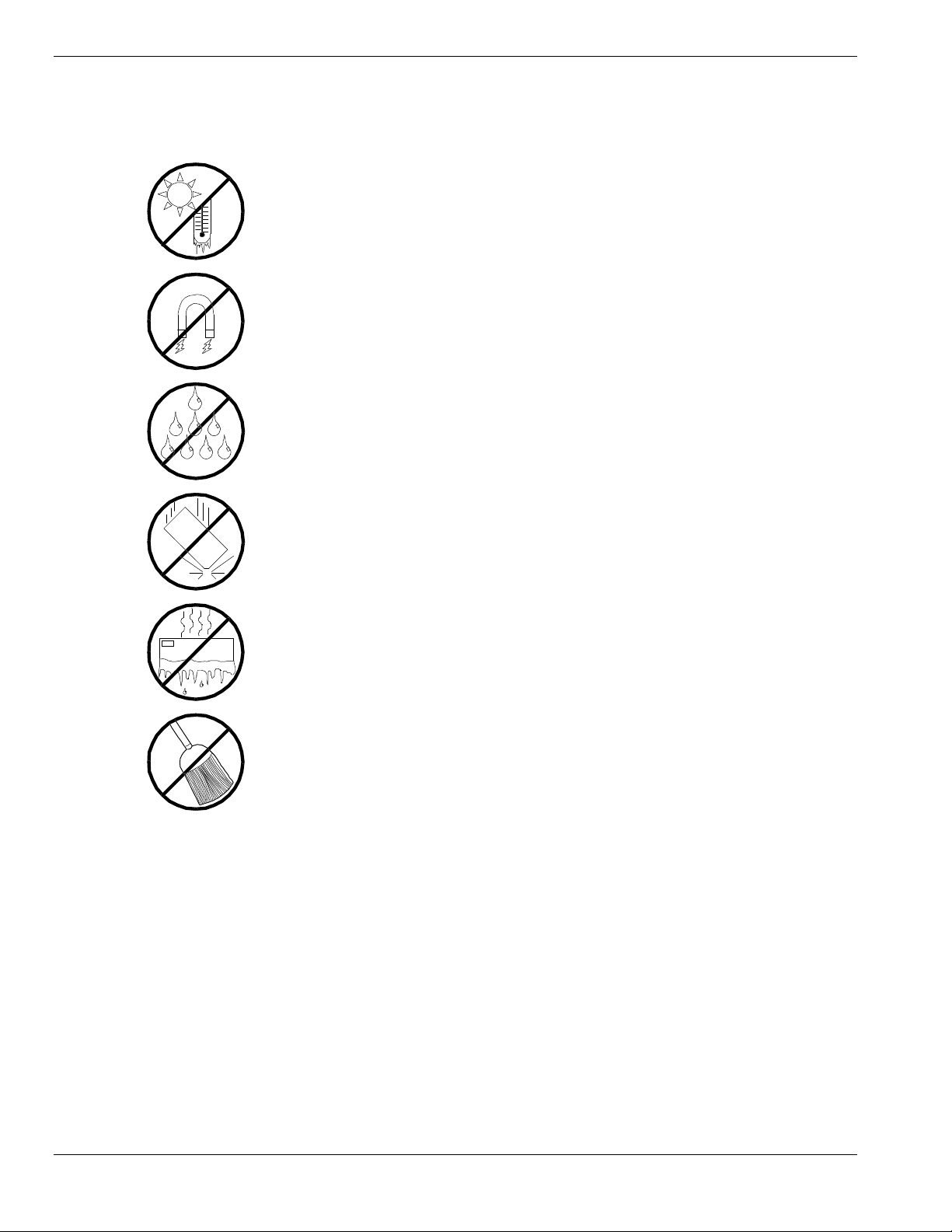
Care and Handling
Use the following guidelines to pro p er ly handle and care for your syste m.
Protect the system from extr emely low or high
temperatures. Let the system warm (or cool)
to room temperature before using it.
Keep the system awa y from magneti c forces.
Keep th e system dry. Do n ot wash the
system with a wet cloth or pour fluid
into it.
Prot ect t he s ystem from bein g bum ped or
dropped.
Check the system for con densa tion . If
condensation exists, allow it to evaporate
before powering on the system.
Keep th e system away fr om dust , sand,
and dirt.
xii Using This Guide
Page 15

System Overview
Overview
Chassis
System Board Features
Peripheral Devic es
System Powe r
Software Locks via the BIOS Set up
1
Page 16

Overview
The server is a modular, multiprocessing server based on the Intel Pentium®
II Xeon chip set. The chip set incor po r ates a modular sca lea ble arc h itect ure that
integrates a 64-bit bus interface with three Peripheral Co mponent I nt er connect
(PCI) buses and an Indust r y Standard Arc h itect ure (ISA) bus. The architecture
supports Symmetrical Multiprocessing (SMP) and a variety of operating
systems. The chassis and system boards ar e des igned to meet the needs of the
server marketplace.
The combination of comput ing performance, memory capacity, and integrated
I/O provides a high performance environment for many applications including
network servers and multi-user syste ms. The server is designed for use in
applications where downtime must be minimized. To this end, the server
includes or has the option to include the following.
Power system redundancy; in a system configured with redundant power
Se lf- c ontained powe r s upply units that c a n be easily ins talle d or removed
Hot-swap Ultra2 SCSI-3 hard drive bays accessib le from the front of the
supplies, the system will continue to operate with a single power supply
failure.
from the back of the chassis.
chassis; a failed drive can be removed, and a new drive installed without
system power being turned off.
High degree of SCSI hard disk fault tolerance and advanced disk array
management features through the use of RAID (Redundant Array of
Independent Disks) technology.
Hardware monitors (temperature and voltage) and software monitors to
indicate failure s.
Easy access to all part s for service.
1-2 System Overview
Page 17

System Feature Summary
A summary of the system features is included in Table 1-1.
Table 1-1. System Features
Feature Description
Modular board set System is intended for use with a modular board set based on Pentium III
Xeon processor technology; from one to four 500 MHz processors and up
to 8 GB of memory.
Add-in board support System I/O board supports up to 11 add-in boards (ten PCI boards,
including four slots supporting 64-bit PCI boards, and one combination
PCI/ISA board slot).
3 1/2-inch diskette drive 3 1/2-inch diskette drive is externally accessible.
One location f or a 3 1/ 2-inc h
removable media device
5 1/4-inch SCSI CD-ROM 5 1/4-inch CD-ROM drive is externally accessible.
Three locati ons for 5 1/4-
inch removable media
devices
12 locations f or 3 1/2 - inch
Ultra2 Wide SCSI-2 hard
drives
Hot swap-capable
backplane
Power supply From two to three 560 Watt autoranging power supplies are easily
Software: utilities, setup BIOS Setup and Symbios Configuration Utility. The E
Security
One extern ally acc essible 3 1/2-inc h half -hei ght bay i s avai lable for s erver
expansion.
Three externally accessible 5 1/4-inch half-height bays are available for
server expansion (diskette, CD-ROM, and/or tape drives).
Three hard disk drive cages; each holding up to four 3 1/2-inch hot-
swappable Ultra2 wide SCSI-3 hard drives. Each cage is secured behind
a metal EMI door; drives can be swapped in or out of the system without
powering it do w n. The array of drives al lows easy setup of RAID
applications.
A hot swap-capable backplane is part of each drive cage assembly for
SCSI hard drives. The backplane is designed for Ultra2 wide SCSI-3
devices that use the industry standard 80-pin Single Connector Attach
(SCA) connector. The backplane consists of a row of four drive
connectors.
removed/installed for service. In a three-supply system, the third supply is
redundant.
XPRESSBUILDER
CD-ROM contains utilities and dr ivers. The ESM PRO CD-ROM contains
the server management software.
Mechanical: Key lock at the front door. One intrus ion se nsor for front door
to secure diskette, hard di sk, remova ble media device, power on/off
switch, reset switch, top cover, and left/right panel access. Three power
inter-lock sensors one on each side of the chassis and one on top of the
chassis. BIOS: Password enable.
System Overview 1-3
Page 18

Expanding the Server as Needs Grow
A typic a l minimu m s yst e m co n figu r atio n may in c lu de the fo llo w ing :
Board set co nsisti ng of system I/O boar d, CPU ba s ebo a rd with one
500 MHz Pentium III Xeon processor, and one memory board
containing 128MB of memory.
Diskette drive and SCSI CD-ROM drive
Three SCSI hard drive cages with one hard drive and a RAID contro ller
installed
Integrated Network Inter face Contr oller (NIC)
Two 560 watt power supplies (an optional third power supply provides
redundant power)
Onboard 2 MB video memory
System I/O board has o ne co mbination PCA/ISA slot and t en PCI slots
for add-in boards. The syste m I/O board also has a riser board for
external I/O (serial, parallel, video) interfaces.
Chassis can hold six removable media drives: four 5 1/4-inch half-height
bays with a CD-ROM drive installed in one bay; and two 3 1/2-inch halfheight bays with a dis kette dr ive installed .
As server/client needs grow, you can expand system processor capacity,
memory, drives, option boards, and the number of power supplies.
CPU baseboard has four slots for CPUs, for a configurable range of one,
two, three, or four processors.
Two memory board support 32 DIMM devices for up to a maximum
memo ry size of 8 GB of memory.
System I/O board has eleven option board slots (ten PCI and one
combination PC I or ISA slot).
Chas sis can hold six removable media drives.
Three SCSI hard drive cages support up to 12 hot-swap bays for 3 1/2-
inch Ultra2 wide SCSI-3 hard drives.
Confi gur a tion Constr aints
The system has four 5 1/4-inch half-he ig ht ba ys access ib le fro m the front . These
bays are convenient for diskette, tape, and CD-ROM drives (removable media).
Because of the EMI generated by hard drives, the increased susceptibility to
ESD, and cooling requirements, hard drives should not be installed in the 5 1/4inch half- he ig ht bays.
1-4 System Overview
Page 19
Chassis
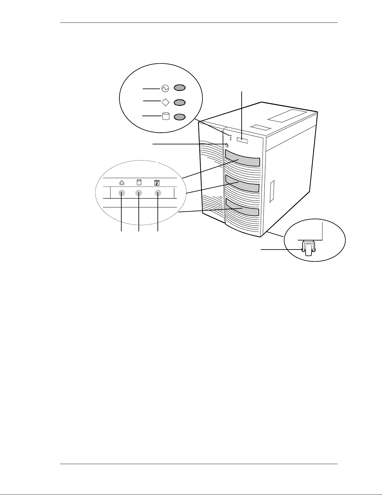
Figure 1-1 shows the server fro nt chassis features and controls.
POWER
A
STATUS
B
C
D
3
FGH
E
DISK
I
A
Power LED When green , power is present in system. When off, power is
turned of f or po w er source is disr upted. See Ta ble 1- 2 for a
list and description of the system LEDs.
B
Status LED
C
Disk LED
D
Key lock
E
LCD panel
F
Drive present/power on
G
Drive acti v e
H
Drive faulty.
I
Casters ( 4) Used when m oving the server. Fixed by the caster holders.
When green the sy stem is OK. See Table 1-2 f or a list and
description of the system LEDs.
When green , internal disk driv es are being accessed. S ee
Table 1-2 for a list and description of the system LEDs.
Secures both front external doors.
Displays information about BIOS and system failures (error
and diagnostic information).
Each drive has three LEDs visible above the bay from the
front. See Table 1-3 for a list of SCSI disk drive status LED
indicators.
Figure 1-1. Front Chassis Features and Controls
System Overview 1-5
Page 20

Status LED In dicator Descr i ptions
Table 1-2 lists the system status LED indicators along with a description of each
LED indicator. Table 1-3 lists the disk drive status LED panel indicators along
with a description of each LED indicator. Table 1-4 lists system status abnormal
conditions.
Table 1-2. System Status LED Indicators
LED Status Description Response
Power Off Power OFF None required (normal)
Green Power ON None required (normal)
Amber Sleep Mode Power saving mode (This feature must
Status Off Power OFF None required (normal)
Green No alarms None required (normal)
be supported by your operating
system).
Amber Abnormal condition
(see Table 1-4)
Disk Off Not accessing disk drives None required (normal)
Amber Internal disk drive failure Check disk drive status LEDs
Green Accessing disk drives None required (normal)
Check condition
Table 1-3. Disk Drive Status LED Panel Indicators
LED Status Description Response
Disk Drive
Present
Disk Drive
Activity
Disk Drive
Status
Off Disk drive not present None required (normal)
Green Disk drive present None required (normal)
Off Not accessing disk drive None required (normal)
On Accessing disk drive None required (normal)
Off No alarms None required (normal)
Amb er Disk drive failure Replace disk drive.
1-6 System Overview
Page 21
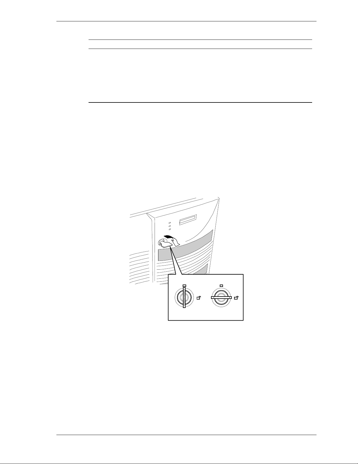
Table 1-4. System Status Abnormal Conditions
LED (Amber) Conditions
System Status
Opening the Front Doors
You must open the right front door to turn the server power on or off, mount or
dismount a floppy disk, or mount or dismount a hard disk drive. Open the left
front door to mount or dismount 5 1/4-inch removable media devices.
Open the front doo rs as follows.
To open the front doors, you need to use the securit y key provided with the
1.
server. Insert the secur it y key into t he key slot and turn the key to the right
(see the following figure).
Chassis intrusion (front cover)
Unit fan alarm
Memory multi-bit error (SERR)
Temperature
Voltage
CPU thermal trip
CPU, memory or option board error or failure
Power supply failure
LOCK
UNLOCK
System Overview 1-7
Page 22
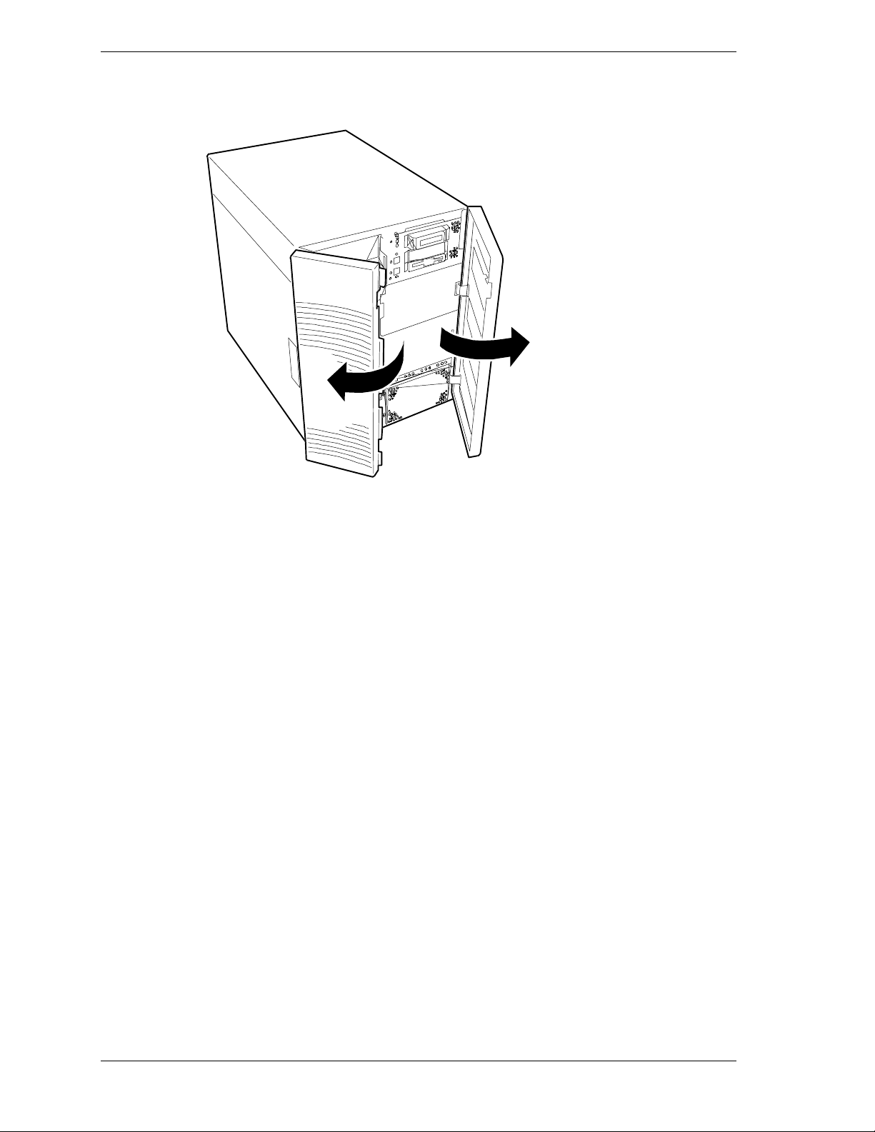
2. First open the right front door, then open the left door (see the following
figure).
1-8 System Overview
Page 23
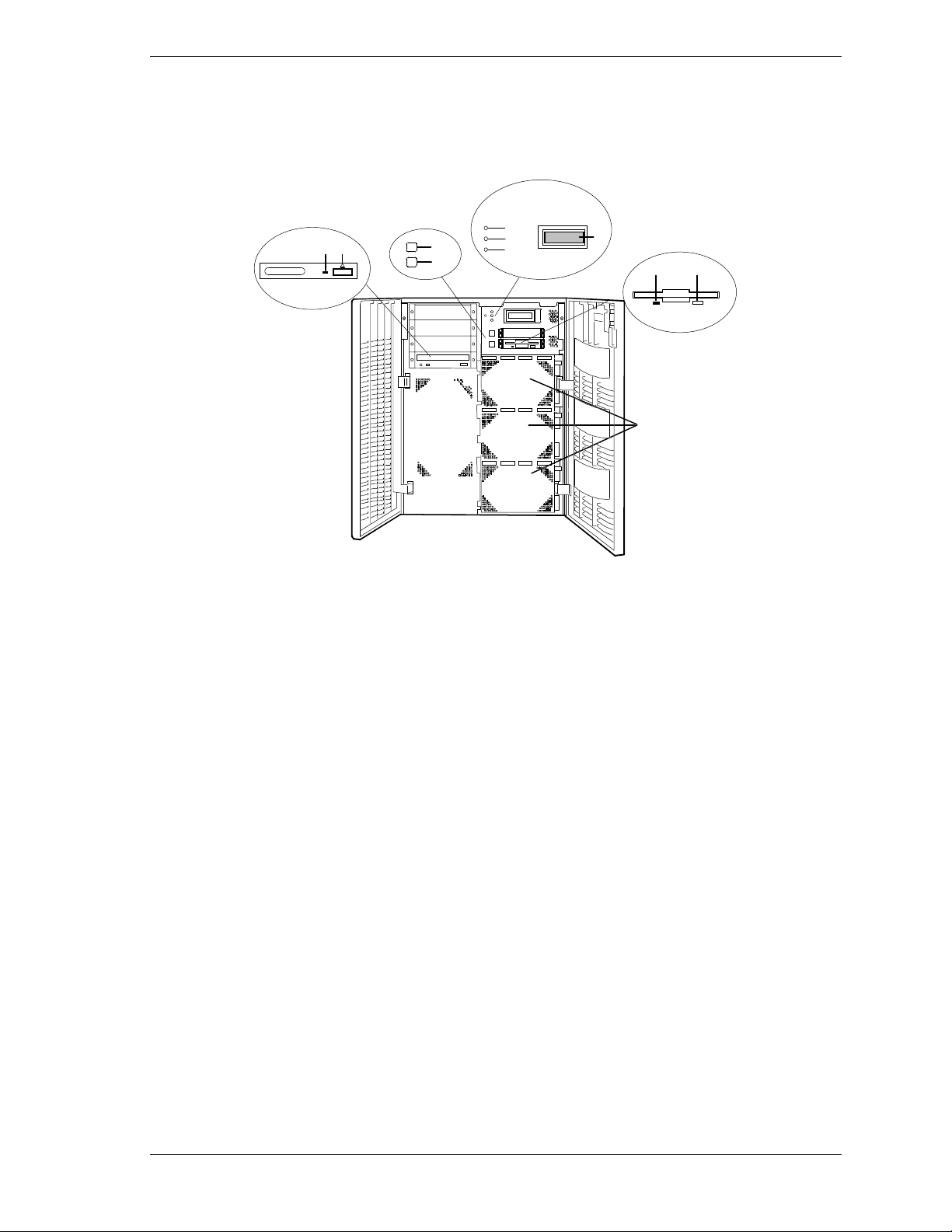
Chassis Fea tures and Contr ol s
Figure 1-2 shows the server fro nt chassis features and controls. Figure 1-3
shows the server rear chassis features and cont rols.
E
J
K
A
SCSI hard drive cages (3) Eac h cage c ontains four disk drives. Ab ove each drive are three
B
Ejector button, 3 1/2-inch
diskette drive
H
I
status LEDs. Refer to Table 1-3 for information on disk drive
status LEDs.
Press to eject diskette.
F
G
D
CB
A
C
Activity light, 3 1/2-inch
diskette drive
D
LCD panel Displays information about BIOS and system failures (error and
E
Power LED When green , power is present in system. When off, power is
F
Status LED When gr een the syst em is OK. See Table 1-2 for a list and
G
Disk LED When green, internal disk drives are being accessed. See Table
H
DC power switch Press to turn system DC power on or off.
I
Sleep swi tch Press to en ter p ower sa ving (s leep) m ode. Press a gain to enter
J
Load/eject button, CD-ROM
drive
K
Activity light, CD-ROM drive When lit, drive is in use.
When lit, drive is in u se.
diagnostic information).
turned of f or po w er source is disr upted. See Ta ble 1- 2 for a list
and description of the system LED indicators.
description of the system LED indicators.
1-2 for a list and description of the system LED indicators.
normal mode of operation. This feature must be supported by
your operating system.
Press to load CD and eject CD.
Figure 1-2. Front Chassis Features and Controls (front doors opened)
System Overview 1-9
Page 24
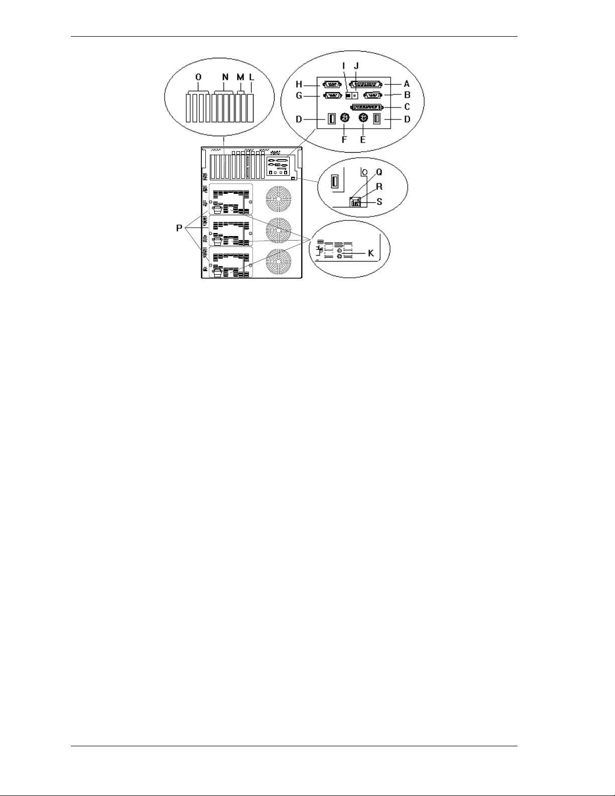
A Printer LPT1 25-pin parallel port connector.
B Monitor VGA monitor 15-pin connector.
C External-SCSI Narrow-SCSI 50-pin connector
D USB USB interface connec tor. Appropriate driv er r eq uired.
E Keyboard PS/2-c om p ati bl e 6- pi n mi ni- D I N c onnector.
F Mouse PS/2-comp ati bl e 6- pi n mi ni-DIN conn ec t or .
G COM2 COM2 serial port 9-pin connector.
H COM1 COM1 serial port 9-pin connector.
See
I Function select
switches
J Reset Button P ress to reset system.
K Power statu s
LEDs
L ISA/PCI slots One ISA/PCI (PCI#11) combination add-in board slot.
M PCI Slots Two PCI add-in board slot locations (PCI #12 and PCI #13).
N PCI Slots Four 64-bit add-in board slot locations (PCI # 31, PCI #32, PCI#33, and PCI#34).
O PCI slots Four PCI add-in board slot locations (PCI #21, PCI #22, PCI #23, and PCI #24).
P Power supplies
(three shown)
Q Status LED Lit when system is connected to a 10Base-T LAN Network; not lit when system is
R Active LE D Lit when information pac k ets are exc h anged bet w een the s ys t em an d the network.
S LA N 10Bas e-T /1 00 Base-T X network LAN connector.
Configuring Switch and Jumper Settings
Both indicators are gr een duri ng nor m al op eration. Eith er or both indicators go off when
power supply fails.
Possible configurations, installed from bottom most bay:
2 supp lies (nonredunda nt), 3 supplies (one redundant).
Each power supply has a separate AC input powe r connector.
connected to a 100Bas e- T X LAN N etw or k
in Chapter 3 of this User’s Guide.
Figure 1-3. Rear Chassis Features and Controls
1-10 System Overview
Page 25
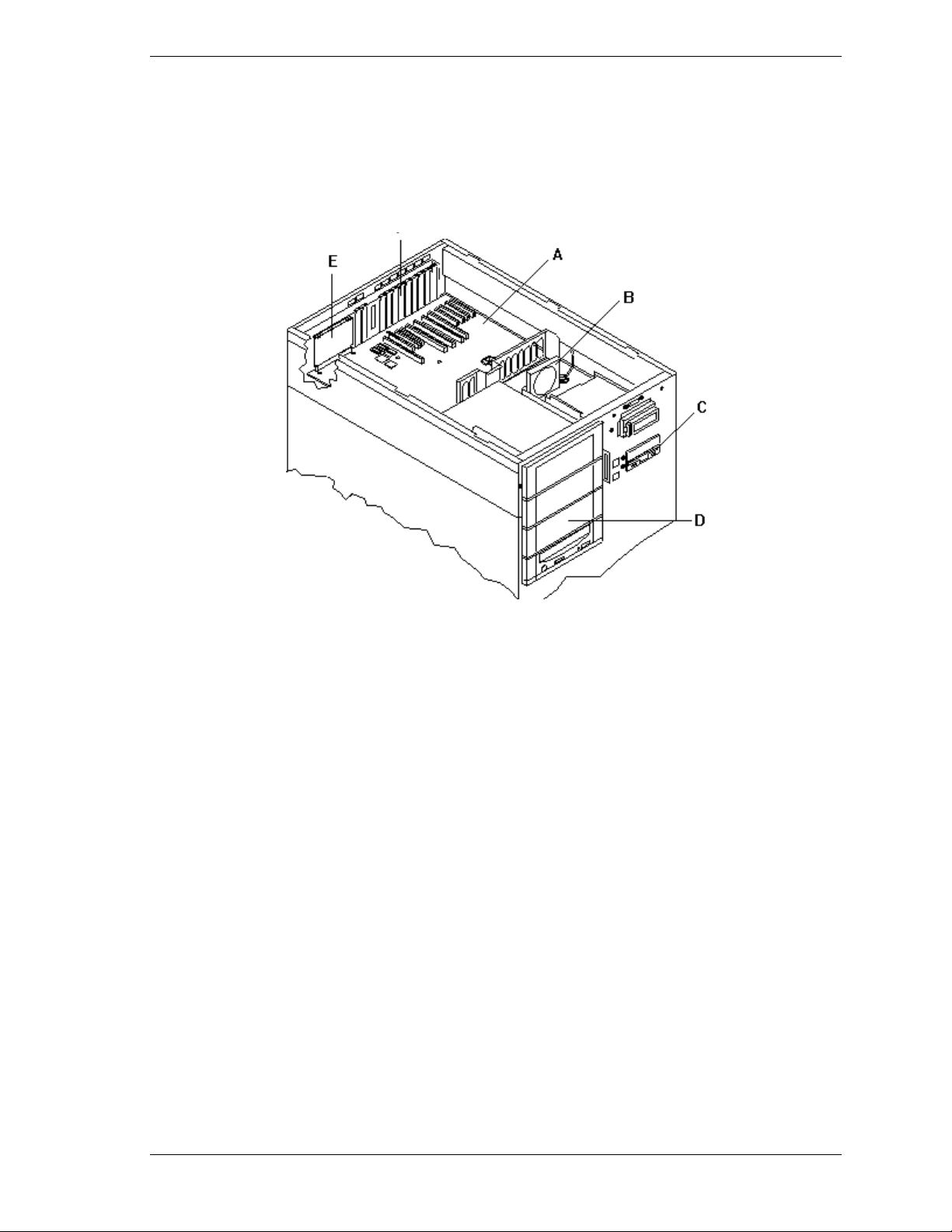
System Board Features
The board set includes the system I/O board, CPU baseboard, and one or two
memory board. The system I/O board is mounted at the top of the system.
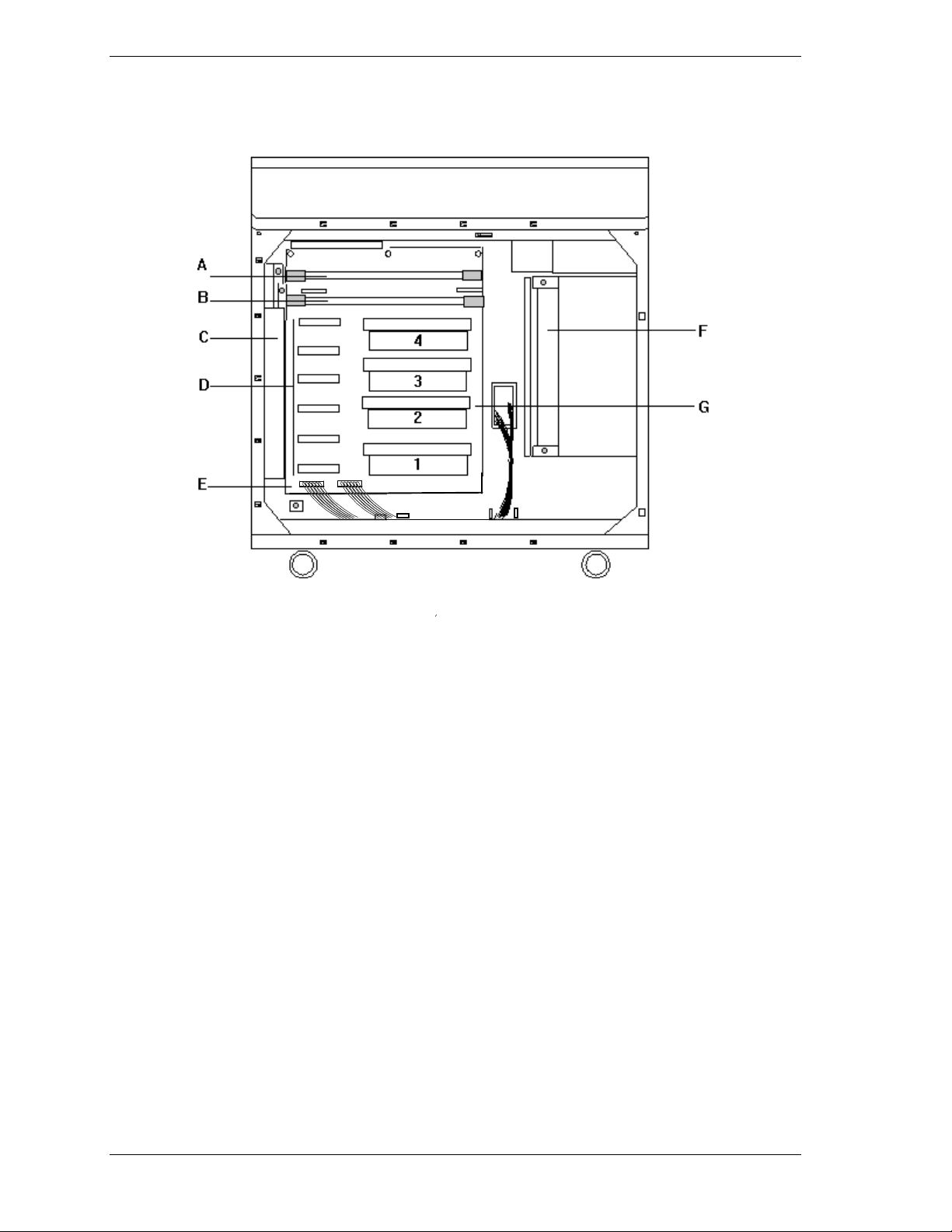
Figure 1-4 shows the system with the top cover removed.
F
A
System I/O Board
B
Option board Fan
C
Diskette drive
D
Four 5 1/4-inch half-height bays with a CD-ROM
drive installed in bottom bay
E
I/O ris er boa rd
F
Expansion slot covers
Figure 1-4. System I/O Board Location
System Overview 1-11
Page 26
The CPU base board plugs into the underside of the system I/O board and the
memory board plugs into the CPU base board. Figure 1-5 shows the system with
the left side cover removed.
A Memory B o ar d #2 o r Mem o ry
Termin ator Board
B Memory B o ar d #1
C Rear Fans (3) Top fan cools memory;
bottom two fans cool CPUs
D Voltage Regulator Module sockets
(VRM1 - VRM6)
E CPU Baseboard
F Front Fans (3) Top fan cools memory;
bottom two fans cool CPUs
G Pentium III Xeon processors (1 - 4)
Figure 1-5. CPU Base Board and CPU Board Location
1-12 System Overview
Page 27

Figures 1-6, 1-7, and 1-8 show the major components on the system I/O board,
CPU baseboard, and memory board. T able 1-5 summarizes the features of the
boa rd set.
Table 1-5. Features of the Board Set
Feature Description
Multiple processor
slots
Upgradable
memory
Add-in board
support
SCSI controller Dual onboard SCSI-2 controller (PCI-based).
BIOS Flash memory-based BIOS (Basic Input/Output System ) and Setup
Video Integr ated super VGA controller ships with eit her 2 MB of video
External device
connectors
Clock Real-time clock/calendar (RTC).
System hardware
monitoring
Configuration
utilities
Four processor sockets on the CPU baseboard.
Sixteen DIMM sockets on each of two memory board, supporting up to
8 GB memory using 256 MB DIMMs.
One combination ISA/PCI bus slot, four dedicated 64-bit PCI bus slots
and six 32-bit PCI bus slots on the system I/O board.
utilities.
memory.
Onboard connectors for two serial ports, parallel port, narrow SCSI port,
PS/2-compatible keyboard, mouse, VGA monitor and 10/100Base-TX
Network LANs.
Detects chassis intrusion and contains sensors for temperature,
voltage, fan failure and Power supply failure.
BIOS Select and Symbios Configuration Utility.
System Overview 1-13
Page 28
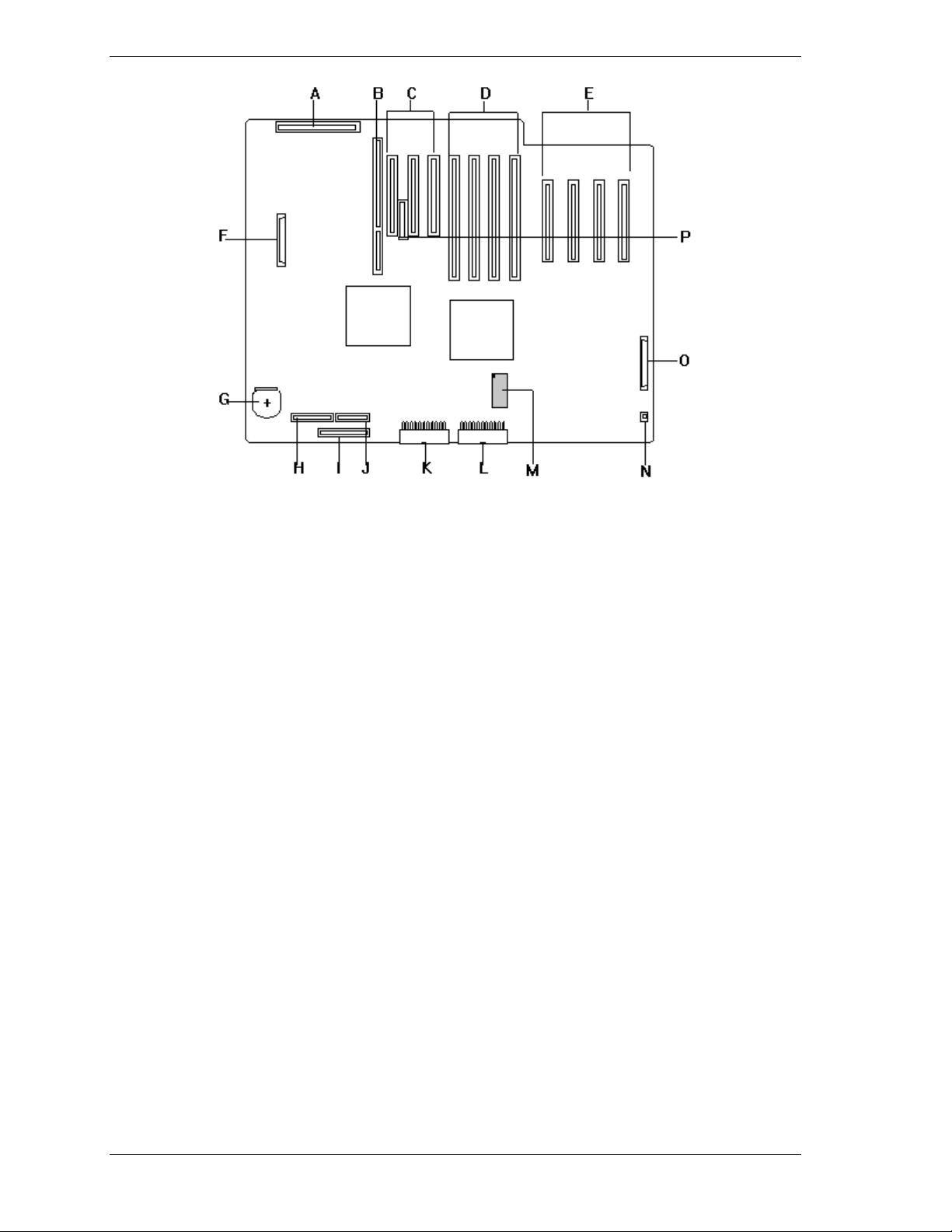
A
Riser Card Connecto r
B
ISA Board Slot
C
First PCI Board Slots (32-bit) (PCI #11, PCI #12 and
PCI#13 from the left).
D
Third PCI Slots (64-bit) (PCI #31, PCI #32, PCI #33
and PCI #34 from the left).
E
Second PCI Board Slots (32-bit) (PCI #21, PCI #22,
PCI #23 and PCI#24 from the left).
F
Ultra2 SCSI-3 SCSI Ch1 Connector for 5 ¼"
Removable Media Devices
G
Battery (lithium)
H
Power PB Connector
I
Floppy Disk Drive Connector
J
Front Panel Connector
K
Power Connector 1
L
Power Connector 2
M
N
O
P
Figure 1-6. System I/O Board Connector and Component Locations
1-14 System Overview
Non-volatile Memory (NVRAM)
Fan Connector
Ultra2 SCSI-3 SCSI Ch2 Connector (not used)
Server Management Board Connector
Page 29
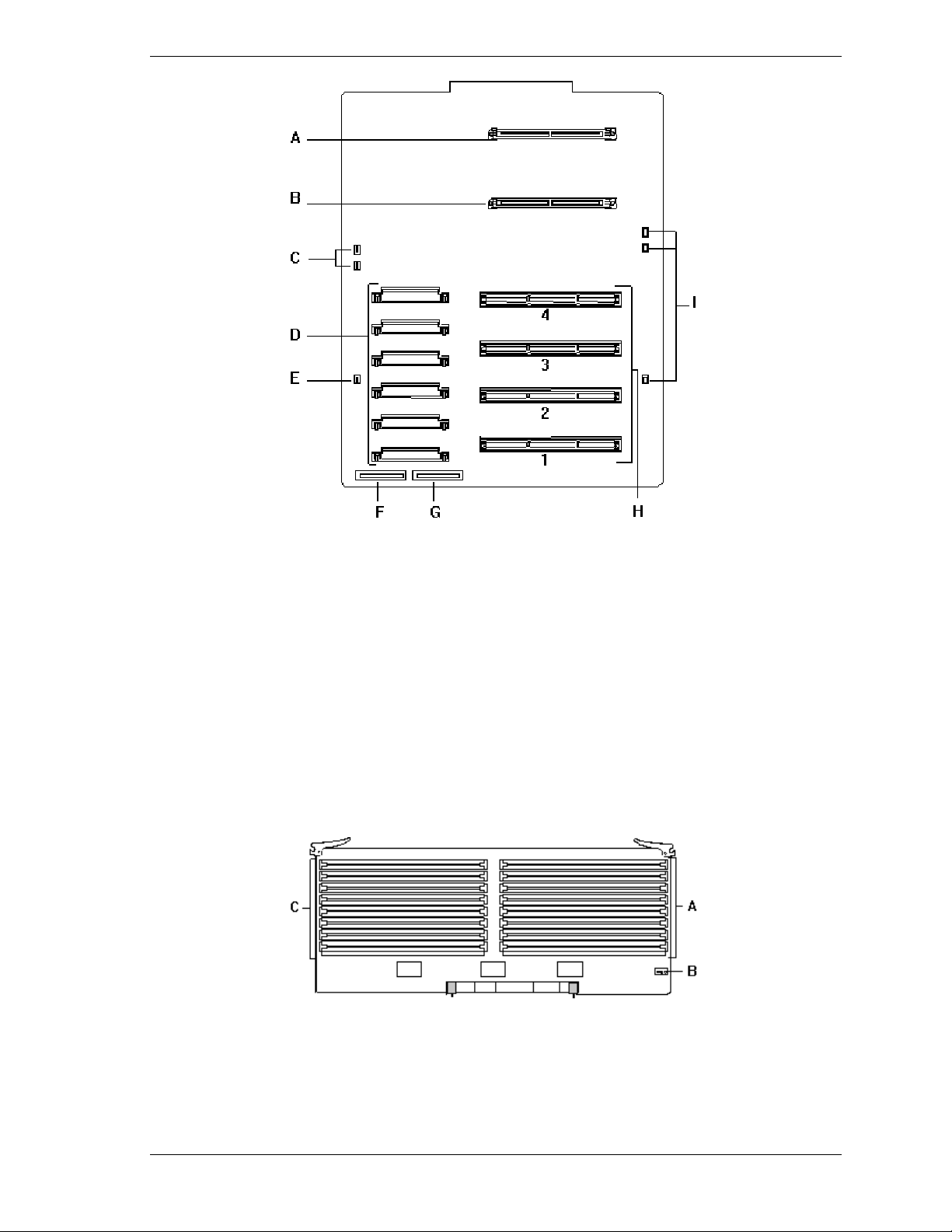
A Memory b oa rd connector (O ptional)
B Memory board connector (Standard)
C Rear Fan Connector (2)
D Voltage module socket (VRM1 - VRM6)
E Rear Fan Connector (1)
F Power Connector 1
G Power Connector 2
H Pentium III Xeon Processors sockets (1 - 4)
I Front Fan Connectors (3)
Figure 1-7. CPU Base Board Component Locations
A DIMM sockets
B Configuration jumper
C DIMM sockets
Figure 1-8. Memory Board Component Locations
System Overview 1-15
Page 30

Processor
Each Pentium III Xeon processor is packaged in a single edge contact (S.E.C.)
cartridge. The cartridge includes t he processor core with an integrated 16 KB
primary (L1) cache; the secondary (L2) cache (512K, 1MB or 2MB); a thermal
plate; and a back cover. The cartridge is secured by a retention module att ached
to the baseboard. Depending on configuration, your system has one to four
processors (see Figure 1-7). Additional Pentium processors enhance
performance and enable symmet ric multiprocessing (SMP) . All processors
access the same memor y and I/O space and t asks can run o n either CPU if your
operating system (OS) supports SMP.
Memory
The system supports a maximum of two memory boards. E ach memory board
contains sixteen 168-pin DIMM sockets (see Figure 1-8, A and C). A minimum
system configuration includes 128 MB (using four 32 MB DIMMs) of syste m
memory. Sixtee n DIMM sockets on each memory board a llow for s ystem
memory expansion up to 8 GB (using sixteen 256 MB DIMMs on each memory
board). ECC generation/checking is provided for detection and correction of
memory errors.
Only use DIMMs approved for use in this server
Note:
system. Call your custom er service representative for
information.
Bus Master I/O Expansion Slots
The server's expansio n capab il it ies meet t he needs o f high performance I/O
servers by providing a combination of PCI local bus and ISA connectors. The
system I/O board offers ten dedicated PCI slot s, four of which are 64-bit, and
one combination slot that may be configured as a PCI slot or an ISA slot. The
ISA architecture supports 32-bit memory addressing and 16-bit data transfers for
the CPU, DMA, and bus mast ers.
Real-Time Clock/Calendar
The real-time clock provides syste m clock/calendar information stored in a nonvolatile memory (NVRAM) (Figure 1-6, M). The real-time clock battery (see
Figure 1-6, G) provides power backup for the real-time clock.
BIOS
A BIOS and Setup Utility are located in the Flash memor y on the syst em I/O
board and include support for system setup and PCI/ISA Plug-and-Play autoconfiguration. A number of security, re liabilit y, and manageme nt featur es ar e
also incorporated to meet vita l server needs.
1-16 System Overview
Page 31

Video
The onboard super VGA controller (PCI ) is a high-perfor mance SVGA
subsystem that supports:
BIOS compatibility with VGA, EGA, CGA, Hercules Graphics, and
MDA
2 MB of Video Memory
16-bit bus for high-speed displa y memor y access
Hardware accelerated bit block transfers ( BIT BLT )
72Hz refresh, non-interlaced at: 640x480, 800x600, or 1280x1024
resolutions
Up to 16M colors at 640x480 and 800x600 resolutions, 64K colors at
1024x768 resolutions and 256 colors at 1280x1024 resolutions with the
optional 2 MB video memory.
SVGA drivers may be required to use the hi gh-
Note:
performance video modes.
SCSI Controller
The system I/O board includes a dual Symbios Ultra2 wide SCSI-3 controller
integrated as a PCI bus master. This controller supports data paths of 8-bit
(fast/narrow SCSI) at a data transfer rate of 10 MB/sec and 16-bit (fast/wide or
ultra /wide SCSI) at a data transfer rate of 20 MB/sec or 40 MB/sec. As a PCI
bus master, this controller supports burst data transfer rates up to the maximum
of 133 MB/sec.
On this server, Channel 1 is cabled to SCSI devices in the removable media
drive bays. Channel 2 is available for optional external SCSI devices.
Peripher al C o ntroller
The advanced integrated peripheral contro ller supports two serial ports and one
parallel port through the I/O riser board (see Figure 1-6, A). The advanced
integrated peripheral controller also supports the connection of two diskett e
drives (see Figure 1-6, I).
External Device Connectors
The I/O panel provides connector s for a PS/2 compatible mouse and a keyboard,
connectors for VGA monitor, two serial port connectors, a parallel port
connector and two US B interface connect ors. It also provides a narrow SCSI
external connector.
System Overview 1-17
Page 32

Keybo ar d an d Mo us e
The keyboard/mouse cont ro ller is PS/2-co mpat ible.
Fans
In addition to the power supply fans, the system has an option board fan cabled
to t he I/O boar d and six f ans cabled to t he CPU bas eboard. The six fans (front
and rear) are redundant in configurat ion. If one fan fai ls, its associated fan
changes its r o tating speed to high.
Peripheral Devices
The following paragraphs describe the Ultra2 wide SCSI-3 hard drive bays and
5 1/4-inch removable media drive bays.
Ultra2 Wide SCSI-2 Hard Drive Bays
The right side of the system contains three Ultra2 SCSI-3 hard drive cages for
3 1/2-inch SCSI-3 hard drives (see Figure 1-9). Each hard drive cage has a hot-
swap backplane that supports four drives. The backplanes require an 80-pin
single connector attachment (SCA) connector on the drives you insta ll.
A drive carrier is required as part of the hot swap implementation. A 3 1/2-inch
peripheral between 1.0 and 1.6 inches high can be accommodated in each
carrier. A drive is mounted in the carr ier with four fasteners, and the carrier is
retained in the chassis by a locking handle.
A fault light on the front panel board g ives a genera l indication that there has
been a fault on a hot-swap drive. Each drive has a set of three lights to indicate
the fault or other status: power-o n (green LED), activity (green LED), or fault
(yellow LED).
1-18 System Overview
Page 33

Three hard drive cages
(EMI panel and exterior door
shown open)
Figure 1-9. Ultra2 Wide SCSI-2 Hard Drive Bays
The backplane has two main functions: SCSI drive control and system dat a
logging. Drive status is monitored to detect failing drives and to control LED
indicator s. T he backplane features include the following:
insertion and removal of hard drives while power is on (referred to as
“hot swap”)
simplif ied ca ble mana gement
SCA connectors to simplify inserting and removing hard drives
SCSI management of fault LEDs.
Each backplane supports SCSI drives with SCA connectors.
Removable Media Drive Bays
On the upper left side of the system, four 5 1/4-inch half-height bays (see
Figure 1-10) are designed for peripherals with removable media (diskette, CDROM, tape). Two available adjacent 5 1/4-inch bays can be converted to a
single fu ll-he ight bay. The 5 1/4-inch d rives c an be remove d direc tly fr om the
front of the chassis. Remova l o f the syst em top cover may be required to
install/remove t he device cables. Cosmetic filler panels are installed over all
unused 5 1/4-inch bays.
System Overview 1-19
Page 34

Factory-installed CD-ROM reader plus
three bays for removable media
drives.
Factory-installed 3 1/2-inch diskette
drive plus second bay for removable
3 1/2-inch drive.
(Exterior doors shown open)
Figure 1-10. Removable Media Drive Bays
On the upper right side of the system, below the LCD panel, are two built-in
3 1/2-inch bays. One contains a 3 1/2-inch diskette drive that supports both 720
KB and 1.44 MB media (see Figure 1-10).
Note:
the last SCSI drive of the dai sy chain cabling (bottom media
bay). All other dev ic es must have terminators removed.
System Power
The system may be configured with up to three 560 Watt power supplies. Each
supply automatically switche s between these input voltage ranges:
100-125 VAC at 50/60 Hz; 10.5 A maximum current
200-240 VAC at 50/60 Hz; 5.5 A maximum current
Each power supply provides DC outputs of +5 V, +12 V, +3.3 V, -5 V, and
-12 V. All output grounds connect to the power supply chassis and to earth
ground through the AC line cord. Each supply has:
Individual AC input line cord that plugs into the external side of the
power supply
Isolating device on each DC output so that t he failure of one supply does
not affect the operation of the others
Cooling fan integral with each power supply enclosure. The fan circuit
implements fan failure detection.
The SCSI terminati on r esi stor s must be installed in
1-20 System Overview
Page 35

In a system, power is drawn equally from all supplies installed. A system with
two power supplies can be fully loaded (all drive bays and add-in board slots
filled). The supp lies use a forced cur r ent - shar ing technique t hat ensures the
supplies share within 10 percent at full load. In a high-access system with three
power supplies, the third supply gives redunda ncy, becau se the load is
redistributed if one supply fails.
Software Locks via the BIOS Setup
The BIOS Setup has software feat ur es t hat let you cont rol access to one or more
parts o f the s ystem:
Set and enable an administrative password
Set and enable a user password
Enable password on boot
Disable writing to the diskette drive when secure mode is set.
If only a supervisor password is set and enabled, enter this password to boot the
server.
If both the user and administrative passwords are set and enabled, enter e ither
one to boot the server. Enter t he ad ministrative password to access the BIOS
Setup to change the system configurat ion.
System Overview 1-21
Page 36

Page 37

Setting Up Your System
Selecting a Site
Unpacking the System
Moving the System to the Site
Getting Familiar With the System
Making Connections
Connecting the Power Cords
Powering On Your System
2
Page 38

Selecting a Site
The system operates r eliably in a t ypical o ffice en vironme nt . Choo se a site that
meets the following requirements.
Site the system near grounded, three-pronged power outlets.
Note:
NEMA 5-15R outlets for 100-120 VAC or NEMA 6-15R
outlets for 200- 240 V A C. For ot her i nternational sites, this
means three-pronged power outlets applicabl e for the
electrical c ode of t he r egion.
Be sure the power service connec tion is through a properly
grounded outlet.
For the United States and Canada, this means
!
CAUTION
Each power cord can be plugged into a separate phase of a main AC
supply, assuming the circuit is rated for that load.
Note:
For Denmark, the system must be c onnec ted to an
AC power source rated at 16 amps.
Select a site that is clean, dust-free, and well vent ilated. Keep front and
rear ventilating op enings free o f obstr u ctions. Locate the system away
from sources of heat, vibration, or physical shock
Isolate the system from strong electro magnetic fields and electrical no ise
produced by electrical devices (such as air cond it ioners, large fans, large
electric motors, radio and TV transmitters, and high-frequency security
devices)
The site should be spacious enough to provide at least five inches (13
centimeters) behind the system and three inches (eight centimeters) on
each side of the system for proper cooling, airflow, and cable clearance.
Allow at least 11 inches (27 centimeters) in front o f the system for proper
front door clearance.
Position t he system for easy access for system maintenance and
installation of system upgrades.
2-2 Setting Up Your System
Page 39

Unpacking the System
!
CAUTION
Your system weighs between 132 pounds (60kg) and 220
pounds (100 kg) with optional equipment. To avoid personal
injury, make sure you have someone help you lift or move
the system.
When you receive your system, inspect the shipping co ntainers prior to
unpacking. If the shipping boxes are damaged, note the damage, and if possible,
photograph it for reference. After re moving the cont ent s of the containers, keep
the cartons and the packing materials. If the cont ent s appear damaged when you
unpack the boxes, file a damage claim with the carrier immediately. To unpack
your system, see the unpacking instr uctions on the shipping carton.
Moving the System to the Site
Once you have selected t he system installation site, move it as fo llow s.
1.
Casters are pro v ided on the botto m of the server. S low ly push the server t o
the selected installation locat ion.
!
CAUTION
For safety reasons, be sure to attach the caster holders on
the casters when the system is at the selected site.
2.
To stabilize the syst em, attach the caster holders on t he casters as shown
below.
Setting Up Your System 2-3
Page 40

Getting Familiar With the System
Before sett ing up your system, see Chapter 1, “System Overview,” to become
familiar with syst em features, such as the location of your system's security
keylocks and front and rear panel switc hes, indicators and connecto r s, etc.
Making Connections
Connect your keyboard, monitor, and mouse (see Figure 2-1). Connect any
external peripheral devices such as a printer or modem by following the
instruct ions included with t hese devices. To connect external SCSI cables, re fer
to Cabling in Appendix A.
!
CAUTION
Damage to the system may resul t if the k ey boar d c able is
inserted or removed when power i s appl ied to the system.
!
CAUTION
Inserting a telephone line connector into a LAN board RJ-45
port may result in personal injury and equipment damage.
2-4 Setting Up Your System
Page 41

A
B
C
D
E
F
G
H
I
J
A.
Connections to optional disk cabine t
B.
Device with the serial interface such as modem
C.
Printer with the parallel interface
D.
Monitor display unit
E.
External SCSI device
F.
Device with the USB interface such as terminal
adapter. Requires NOS supporting USB interface.
G.
Keyboard
H.
Mouse
I.
Device with the USB interface* such as terminal
adapter
J.
Hub (multi-port repeater)
K.
Network system on LAN (to be connected via a hub)
K
Figure 2-1. Making Connections
Setting Up Your System 2-5
Page 42

Connecting the Power Cords
Plug the female end of each AC power cord into the input receptacles on the
rear of the power supplies (see Figure 2-2). Plug the male end of each power
cord into NEMA 5-15R outlet for 100-120 VAC or NEMA 6-15R outlet for
200-240 VAC. If the power cords supplied with the system are not compatible
with the AC wall outlet in your region, obtain a suitable power cord that meets
the following criteria.
The power cord must be rated for the available AC voltage and have a
current rating that is at least 125% of the current rat ing of the system.
The power cord connector that plugs into the wall outlet must be
terminated in a grounding-type male plug designed for use in your region.
It must have certification marks showing certification by an agency
acceptable in your region.
The power cord connector t hat plugs into the syst em must be a n IEC-
type CEE-22 female connector.
The power cord must be less than 1.8 meters (6.0 feet) long.
!
WARNING
Your system shipped with two AC power cords. Do not
attempt to modif y or use the supplied AC power cords if it
not the exact type requi r ed.
Figure 2-2. Connecting the AC Power Cord
2-6 Setting Up Your System
Page 43

Powering On Your System
Power o n you r system as follows.
1. Make sure all external devices, such as a video display, keyboard, and
mouse (optional) have been connected, and t he power cor ds are connected.
2. Power on the video display and any other external devices.
3. Open the right front door and press the power on/off switch on the front
panel (see Figure 2-3).
4. Verify that the Power LED is lit. If it is not lit, ensure the AC power cords
are connected to functional AC power sour ces.
After a few seconds your s yst em begins the internal Power-On Self Tests
(POST). POST automatically checks the system, CPU module, memory,
keyboard, and most installed peripheral devices. If you have problems powering
on your system, refer to Problem Solving in Chapter 6.
After you have successful l y powered on your system, veri f y that t he syst em
boo ts to a DOS pr ompt . You c a n now run the E
XPRESSBUILDER
CD-ROM.
Power LED
Power On/Off Switch
Figure 2-3. Powering On Your System
Setting Up Your System 2-7
Page 44

Page 45

Configuring Your System
Configuring Your System
BIOS Setup Utility
Symbios Confi gurati on Utility
Configuring the RAID Controller
Configuring Syst em Jumpers and Switches
3
Page 46

Configuring Your System
Configuration and setup utilities are used to change your system configuration.
You can configure your system, as well as any option boards you may add to
your system, using the BIOS Setup (stored in the system FLASH memory). A
diskette is not needed to run BIOS S et up.
The SCSISelect Utility, also stored in the system FLASH memory, is used if
you need to configure the SCSI controller in your system or to perform a SCSI
disk format or verify disk operation of these dr ives. A diskette is not needed to
run SCSISelect.
A Ut ilities di s kette contains the Event Log Utility. The Event Lo g Utility is u s e d
to read stored syste m event information.
If your system has been facto ry configured, the BIOS Setup or SCSISelect
utilities do not need to be run unless you want to change the password or
security features, add option boards or devices, or upgrade the boards in your
system.
There are some system configuration parameters that are set by jumpers.
However, these parameter s do not usua lly require change. T he following
sections provide procedures for running the BIOS Setup, and the Utilities
diskette. Also, a section describing the system jumper configurations is
presented. Several configurat ion tables are a lso pro vided to r ecor d changes you
make to the default system configuration.
You use the E
XPRESSBUILDER
CD-ROM to create the Utilities diskett es.
3-2 Configuring Your System
Page 47

BIOS Setup Utility
The BIOS Setup Utility, is used to change system configuration parameters. The
utility is resident in the system FLASH memory and does not require a diskette
or an operating syste m present to run.
When to Use the BIOS Setup Utility
In most cases, it is not necessary to run the BIOS Setup Ut ility to change the
default parameters, since the default settings support most system
configurations. In the following cases, however, you should initiate this utility
to change the default settings.
When the set parameters are inco rrect : The parameters set with the BIOS
Setup Utility are sto r ed to the nonvolat ile memory called CMOS. If the contents
of this CMOS have been destroyed due some reason, an error message appears
on the display during the execution of POST (Po wer On Self-Test) . When an
error message appears, press the F2 key to enter the BIOS Setup Utility.
When the CMOS is cleared: A jumper, with which you can clear the contents
of the CMOS, is provided on the syste m I/O board. If this jumper is used to
clear the contents of the CMOS, a message appear s requesting you to run the
BIOS Setup Utility during the execution of POST. Run the BIOS Setup Utility
according to the instr uct ions d isp la yed on t he screen and provide necessary
settings.
When the boot device priority is changed: The defaults instruct the your
server to search the boot devices in the following order: floppy disk drive, CDROM drive, then the hard disk drive. If you want to change the boot order
priority, run the BIOS Setup Utility to change the settings.
When you replace a processor or memory: Your server has a degradation
function allowing continuation of operation in the event of a processor or
memory error. After replacing the failed processor or memory, run the BIOS
Setup Utility to clear the erro r information.
When you change cache memory configuration: Run the BIOS S et u p Utility
to enable or disable the memory cache, or to set the cache in memor y areas such
as system BIOS or video BIOS.
When you change a setup for a PCI or ISA board: Run the BIOS Setup
Utility to configure the interrupt request (IRQ) for PCI/ISA devices and PCI and
ISA bus slot s.
Configuring Your System 3-3
Page 48

When using the remote power-on function: Enable or disable the remote
power-on (Wake On LAN) function, which is used to power up your server
remotely through a network.
When using the AC link function: AC link allows you to configure the power
ON/OFF state of your server when AC power is restored after a power failure.
Run the BIOS Setup Utility to change the power ON/OFF state of your server
after a power failure.
When enabling and changing password and other security features: The
BIOS Setup Utility includes password setup features and related security
features. Run BIOS Set up to enable and change these features. (Do not set the
password and securit y featur es be fore installing the operating syste m.)
When installing an ISA board (not Plug and Play): Run the BIOS Setup
Utility to reserve system resources, including IRQ, memory addresses, and I/O
addresses used by the board. T his ensures t hat there will not be a conflict with
any Plug and Play controllers in your system.
Other: You can also change other BIOS settings including date/time, keyboard
features, and standard I/O (serial Port and printer port) interrupt. However,
these features can also be c hanged from your operating system menus.
Using the BIOS Setup Utility
You access the BIOS S et up Utility when you tu r n o n or reboot your system. To
run the BIOS Setup Utility, perform the following procedure.
1. Power on or reboot the system. BIOS displays the following:
Press <F2> to enter SETUP
2. Press F2. After BIOS POST completes, the BIOS Setup Utility starts and the
Main Menu is displayed. The menu bar a t the top of t he Main Menu lists the
following se le ctions.
Menu Use
Main Use this menu for basic system configuration.
Adv anced Us e this menu for set ting t he Advanced Feat ures available on your
system.
Security Use this menu to set User and Supervisor Passwords and the Backup
and Virus-Check reminders.
System Hardware Use this menu for configuring unique Server Features.
Boot Use this menu to change the boot order of devices in your system.
Exit Exits the current menu.
Use the arrow keys to select a menu or an ite m on a displayed menu. Press
the value keys (listed in the table below) to cycle through the allowable
values for the selected field. Use the Exit menu’s “Save Values” select ion to
save the current values on all the menus.
3-4 Configuring Your System
Page 49

To display a submenu, posit ion the curso r on a selection that has a submenu
and press
. Selections with submenus are preceded by an arrow.
Enter
See the following table for information on the keys you use with Setup.
These keys are also listed at the bottom of the Setup menu.
Key Function in Setup Menu
F1 or Alt-H General Help window.
ESC Exit the current m enu.
← or → arrow keys
↑ or ↓ arrow keys
HOME or END Move cursor t o top or bottom of window.
F5 o r - Select t he previous value for the field.
F6 or + or SPACE Select the next value for the field.
F9 Load default configuration values for this menu.
F10 Sav e curr ent values and exit.
ENTER
Select a different menu.
Move cursor up and down. The cursor moves only t o the
settings that you can change.
Exec ute comma nd or Select
BIOS Setup Configuration Settings
Table 3-1 shows the normal settings for the BIOS Setup Utility and provides a
place for you to record any changes you make to these settings.
Table 3-1. BIOS Setup Configurations, Main Menu
Menu Parameter Name Normal Setting or
Display On ly
MAIN MENU
➨
submenu.
Your Configuration
Processor Type Displays the type of
processor installed.
Processor Speed Displays the
processor speed.
Cache RAM Displays the cache
RAM size.
Configuring Your System 3-5
Page 50

Table 3-1. BIOS Setup Configurations, Main Menu
Menu Parameter Name Normal Setting or
Display On ly
Cache Memory
Press Enter for menu.
Memory Cache Enabled
Cac he Sys tem BIOS Area Write Protected
Cac he Video BIOS Area Write Protected
Cache Base 0 - 512K Write Back
Cache Base 512K - 640K Write Back
Cac he Extended M emor y Area Write Back
Cache C800-CBFF Disabled
Cache CC00-CFFF Disabled
Cache D000-D3FF Disabled
Cache D400-D7FF Disabled
Cache D800-DBFF Disabled
Cache DC00-DFFF Disabled
System Memory 640KB (display only)
Indicates the total
capacity of the basic
memory.
Your Configuration
Extende d Memo ry XXXMB (display
only) Indicates the
total capacity of the
extended memory.
Language English
BIOS Version Indicates the version
of the system BIOS.
(display only)
System Time
Enter current time (hour, minutes, seconds on
24 hour clock).
System Date
Enter current date.
Floppy Options
Diskette A:
Use +/- to change values; indicates the type of
diskette dri ve install ed.
Diskette B:
Use +/- to change values; indicates the type of
diskett e drive installed (Not Installed in your
system).
Current Time
Current Date
1.44MB, 3 1/2”
Not Installed
3-6 Configuring Your System
Page 51

Table 3-1. BIOS Setup Configurations, Advanced Menu
Menu Parameter Name Normal Setting or
Display On ly
ADVANCED MENU
Advanced
Press Enter for menu.
Plug & Play OS No
Reset Config uration Data No
Address Bit Permuting Enabled
ROMPilot Support Disabled
Memory Reconfiguration
Press Enter for menu.
Memory Reconfiguration Enabl ed
DIMM Group #1 Status Normal (display only)
DIMM Group #2 Status None (display only)
DIMM Group #3 Status None (display only)
DIMM Group #4 Status None (display only)
DIMM Group #5 Status None (display only)
Your Configuration
DIMM Group #6 Status None (display only)
DIMM Group #7 Status None (display only)
DIMM Group #8 Status None (display only)
Clear DIMM Error Press Enter to clear DIMM
error
DIMM Error P a u se Disabl ed
CPU Reconfiguration
Press Enter for menu.
CPU Reconfiguration Enabled
CPU # 1 Stat us Nor mal (display only)
CPU # 2 Stat us Nor mal (display only)
CPU #3 Status None (display only)
CPU #4 Status None (display only)
Clear CPU Errors Press Enter
CPU Error Pause Enabled
Configuring Your System 3-7
Page 52

Table 3-1. BIOS Setup Configurations, Advanced Menu
Menu Parameter Name Normal Setting or
Display On ly
Peripheral Configuration
Press Enter for menu.
Serial Port 1: Enabled
Base I/O Address: 3F8
Interrupt: IRQ4
Serial Port 2: Enabled
Base I/O Address: 2F8
Interrupt: IRQ 3
Parallel Port: Enabl ed
Parall el Mode: Bi-directi onal
Base I/O address: 378
Interrupt: IRQ 7
Diskette Controller: Enabled
Mouse Auto Detect
SCSI controller 1 Enabled
Your Configuration
SCSI controller 2 Disabled
LAN controller Enabled
Monitoring C onfi gurat ion
Press Enter for menu.
POST Monitoring Observation POST-END
Boot Monitoring Disabled
PCI Device
Press Enter for menu.
PCI IRQ line 1
to
PCI IRQ line 1 7 *
PCI Parity Error
PCI Bus#1 Parity Error Enabled
PCI Bus#2 Parity Error Enabled
PCI Bus#3 Parity Error Enabled
* See Table 3-2 for PCI IRQ assignments to PCI bus slot or controller.
Auto Select
3-8 Configuring Your System
Page 53

Table 3-1. BIOS Setup Configurations, Advanced, Security, and System Hardware
Menus
Menu Parameter Name Normal Setting or
Display On ly
ISA Device
Press Enter for menu.
IRQ None
DMA Channel None
Memory Si ze None
Memory address None
Enable Extended Memory Gap Disabled
Numlock
Press Enter for menu.
Numlock On
Key Click Disabled
Key Board auto-repeat rate 10/sec
Key Board auto-repeat delay 1 sec
SECURITY MENU
Supervisor Password is Disabled (display only)
User Password is Disabled (di spla y only)
Set Supervisor Password Press Enter
Set User Password Press Enter
Password on boot Disabled
Diskette Write Normal
Power Switch Mask Unmasked
Option ROM Menu Mask Unmasked
Processor Serial Number Disabled
Your Configuration
SYSTEM HARDWARE MENU
Thermal Sensor
Press Enter for menu.
Thermal Sensor Enabled
Upper Limit 45
Lower Limit 4
Wake On LAN Disabled
AC-LINK Last State
ESM IRQ IRQ 13
SMI Yes
Error Log Initialization No
Configuring Your System 3-9
Page 54

Table 3-1. BIOS Setup Configurations, Boot Menu
Menu Parameter Name Normal Setting or
Display On ly
BOOT MENU
First boot device Diskette Drive
Second boot device CD- ROM Drive
Third boot device Hard Drive
Your Configuration
Table 3-2. PCI IRQ Bus and Controller Assignments
PCI IRQ Line Assignment
PCI IRQ Line 1 SCSI Channel 1 on system I/O board
PCI IRQ Line 2: SCSI Channel 2 on system I/O board
PCI IRQ Line 3: LAN Controller and video controller on system I/O board
PCI IRQ Line 4: PCI #11 (Int A)
PCI IRQ Line 5:
PCI IRQ Line 6:
PCI IRQ Line 7: PCI #21 (Int A)
PCI IRQ Line 8: PCI #22 (Int A)
PCI IRQ Line 9: PCI #23 (Int A)
PCI IRQ Line 10: PCI #24 (Int A)
PCI IRQ Line 11:
PCI IRQ Line 12:
PCI IRQ Line 13: PCI #33 (Int A)
PCI IRQ Line 14: PCI #34 (Int A)
PCI IRQ Line 15:
PCI IRQ Line 16:
PCI #12 (Int A)
PCI #13 (Int A)
PCI #31 (Int A)
PCI #32 (Int A)
PCI #11 (Int B)
PCI #12 (Int C)
PCI #13 (Int D)
PCI #21 (Int D)
PCI #22 (Int B)
PCI #23 (Int C)
PCI #24 (Int D)
PCI #31 (Int C)
PCI #32 (Int D)
PCI #33 (Int B)
PCI #34 (Int C)
PCI #11 (Int C)
PCI #12 (Int D)
PCI #13 (Int B)
PCI #21 (Int B)
PCI #22 (Int C)
PCI #23 (Int D)
PCI #24 (Int B)
PCI #31 (Int D)
PCI #32 (Int B)
PCI #33 (Int C)
PCI #34 (Int D)
3-10 Configuring Your System
Page 55

Table 3-2. PCI IRQ Bus and Controller Assignments
PCI IRQ Line Assignment
PCI IRQ Line 17:
PCI #11 (Int D)
PCI #12 (Int B)
PCI #13 (Int C)
PCI #21 (Int C)
PCI #22 (Int D)
PCI #23 (Int B)
PCI #24 (Int C)
PCI #31 (Int B)
PCI #32 (Int C)
PCI #33 (Int D)
PCI #34 (Int B)
Exiting BIOS Setup
To exit Setup, select Exit fr om the menu bar t o disp lay the E xit Setup menu.
The following describes the options on this menu. Note that ESC does not exit
t his men u. Selec t one of the items from t h e menu or me n u bar to exit this menu.
Selection Description
Save changes and Exit Stores the selections displayed in the menus in CMOS and exits
the Setup program.
Exit without Saving
Changes
Get Default Values Sets default values for all Setup menus. Useful if BIOS detects a
Load Previous Val ues Reverts to previously saved values if t he new values have not
Save Changes Stores the cur r ent selections without exiting the Setup program.
Exits the program without savi ng any changes you have made in
this session. Previous selections remain in effect.
problem with the values stored in CMOS.
been saved to CMOS.
Configuring Your System 3-11
Page 56

Symbios Configuration Utility
The Symbios Configuration Utility detects the two SCSI host adapters located
on the system board. Use the utility to :
Change adapter and SCSI device default values
Check and/or change SCSI device sett ings that may conflict with those of other
devices in the server.
Perform low -level formattin g or ve ri fy operat ions o n SC SI dis k dri ves.
Running the Symbios Configuration Utility
1. Power-on the s ystem. The system bo o ts up.
2. When this message appears on the video monitor:
Press Ctrl-C to start the Symbios Configuration Utility
Press Ctrl+C to run this utility.
3. The utility st arts and the Main Menu displays.
Symbios Configuration Utility Main Menu
Port
Adapter
SYM53C895
(SCSI 1 - 5 ¼"
removable media
devices)
SYM53C895 (SCSI
2 - not used)
Change Adapter Status – Press ENTER to sel ect and change adapter stat us.
Adapter Boot Order – Press ENTER to select and change boot order of each SCSI adapter. (not
required)
Additional Adapter Configuration – Not used.
Display Mode-Verbose – Press ENTER to change display mode.
Mono/Color – Press ENTER to change display from black/white to color.
Language – Not used.
Help/Quit
Number IRQ
Level
4000 11 On On Yes
5000 15 O n On Yes
Current Next Boot
Status
NVRAM
Found
The following keys are active for all SCSI Configuration scree ns:
Key Action
Arrows Up and down arrows move from one parameter to another within a
screen.
ENTER Displays options for a configurable parameter. Selects an option.
ESC Moves back to previous screen or parameter or EXIT if at the Main
menu.
3-12 Configuring Your System
Page 57

Changing the Adapter and Device Configurations
The Symbios Co n f iguration Ut ility Main Menu lists the two onboard SCSI
adapters and shows their current settings. The first adapter listed (SCSI 1)
controls the oper ation of the re movable med ia devices in your system; the
second adapter listed nor mally co nt ro ls t he hard d isk dr ives in the system,
however hard disk drives in your syste m are contr olled by a R AID controller.
To configure SCSI devices, perform the following procedure:
1. Using the arrow keys, select t he adapt er you want to reconfigure. Pr ess
ENTER.
2. Se lect “Adapter Setup” and press ENTER. The Adapt er S et up screen
displays.
Adapter Set u p Scr een
Your Configuration
Description Recommended Setting or
Display Only
SCAM Support Off
Parity On
Host SCSI ID 7
SYM53C8951SYM53C895
2
Scan Order Low to High
Removable Medi a
Support
CHS Mapping SCSI Plug and Play Mapping
Spinup Delay (Secs) 2
Help
Restore Def ault Setup
Exit this menu
None
3. Highlight the function you want to change and press ENTER. You will be
prompted to save changes when you exit the configuration utility.
To change device configuration parameters, perform the following steps:
1. At the Symbios Configuration Utility Main Menu, select the adapter which
connects to the SCSI device you are reconfiguring. The first adapter listed
controls the operation of any SCSI removable media devices inst alled in
your system; the second adapt er is not used.
Press ENTER.
2. Select “Device Selections” and press ENTER. The Devices 0 to 7 screen
displays.
3. Select the SCSI device you are reconfiguring and press ENTER.
4. Highlight the function you want to change and press ENTER. You will be
prompted to save changes when you exit the configuration utility.
Configuring Your System 3-13
Page 58

Description
SYM53C875 Adapter 1 – SCSI Removable Media Devices
Recommended
Setting or
Display Only
Your Configuration
Device Sel ections
Sync Rate 80
Wi dth (bits) 16
Disconn ect On
Read/Write I/O timeout
(secs)
Scan for device at boot time Yes
Scan for SCSI LUNS Yes
Queue Tags Enabled
Initial Bo ot Devic e No
Format – Format a disk
Verify – Verify disk media
Help
Restore Def ault Setup
Exit this Menu
Select device
and press
ENTER.
10
Device Setting
3-14 Configuring Your System
Page 59

Configuring the RAID Controller
The system includes a three channel SecuRAID 530 Redundant Array of
Inexpensive Devices (RAID) Controller board (Mylex eXtremeRAID 1100).
This board gives your system the added security of fault tolerance and is preconfigured at the factory. Use Table 3-2 to determine how your RAID co ntroller
was configured at the factory. If you want to change the RAID level or add
additional hard disks to t he arr ay, use the RAID Configuration Utility.
If you are adding the RAID controller to an existing system, the RAID
Configur atio n U til ity allows you to configure your disk array before installing
your network operating system.
Table 3-2. RAID Configurations
Number of
Hard Drives
1JBOD1 JBOD (Mylex RAI D 7) JBOD is an acronym for Just
21 2 Mirrorin g (RAID 1) Dr ives are paired and mirrored.
35 3 Striping with Parity (RAID 5) Data is striped across
4 or more 5 4 (one standby
RAID Level
Configured
Hard Drives in
Array
drive)
Description
a Bunch Of Disks. Each drive can oper ate
independently as wi th a common host bus adapter; or
multiple drives m ay be spanned and seen as a single
very large drive. No redundancy is provided.
All data is 100% duplicated on an equivalent drive
(fully redundant).
several physical dr ives. Parity protection is used for
data redundancy.
Striping with Parity (RAID 5) with a standby drive
The a rray consists of three ON-LINE dri ves and one
STAN DBY dr ive. The standby replacement drive, or
hot spare, is one of the most important features RAID
provides to ac hieve automatic, non-sto p servi ce wit h a
high degree of fault-tolerance.
The RAID Configuration Utility ut ility is included w ith the RAID cont roller.
The SecuRAID 530 controller supports various versions of RAID technology
(referred to as RAID levels). To use any RAID level, you must configure the
RAID controller using the RAID Configuration Utility configuration utility
prior to installing your Networ k Operating System. For an explanation of this
utility, refer to the RAID Conf iguration Utility Utilities Installation Guide and
User Manual that was shipped with the controller. Chapter 2 of the manual
(Configuration Strategies) describes RAID technology and provides tips on
making your ar ray perfor m well in yo ur spe cific app lication. Chapt er 3
(Preparing the Array) covers array hardware preparation, configuration, and
initialization. After completing the steps in Chapter 3, you can install your
Network Operating System.
Configuring Your System 3-15
Page 60

If you want to remotely configure the array (from a PC client); increase arr a y
capacity online; or monitor statistics on disk and controller activit y, you must
install the Global Array Manager (GAM) o ption provided with your RAID
subsystem. The GAM option includes diskettes and user documentation. Use of
GAM is do cu mented in the Global Array Manager 2 Server Installation Guide.
Increasing array capacity is covered in the MORE User Guide. This user guide
covers enhancements to bot h the Globa l Array manager and RAID
Configur a tion Util ity utilit ie s s oft ware that imp lement online RAID expansion
(MORE) technology.
Configuring System Jumpers and Switches
This section describes t he jumpers and switches used on the I/O riser board,
memory board, and system I/O board.
Before You Begin
Only a qualified technical person should perform the procedures in this section.
Note:
system boards. Modify the boards only at an ESD
workstation. Otherwise, wear an antistatic wrist strap
attached to chassis ground.
The system jumpers ena ble you to set specific operating parameters for your
system. A jumper is a small plastic-encased conductor (sho rt ing plug) that slips
over two jumper pins.
Electrostatic discharge (ESD) can damage the
Configuring I/O Riser Board Function Se lect Switches
The following describes how to configure and set the I/O riser board function
select sw itches for specific operating parameter s. The function select DIP
switches configure the use of the rear panel reset / dump button.
!
CAUTION
Before doing the procedur es i n this section, make sure that
your system is powered off. Unplug all AC power cords from
the back of the chassis. Failure to disconnect power before
setting switches and mov ing jumpers can result in personal
injury and equipm ent damage.
Figure 3-1 shows the DIP sw itches. The sw itc hes consist of a block of four
switches, access ib le o n t he I/O panel locat ed on the I/O r iser boar d at the rear of
the chassis.
3-16 Configuring Your System
Page 61

ON
Function Select Switches and
Reset/Dump Button
OFF
1234
AB
A Function select switches
B Reset/Dump Button
(Switches shown in factory default
position.)
Figure 3-1. Function Select Switches
Note:
your system configur ation. If your system requires a switch
change, change only the switch setting for that conditi on.
Otherwise keep the switches at t heir factory settings.
The switches are set correctly at t he factory for
Table 3-3 shows the switch configurations and functions. Set the switches per
Table 3-3 and the following steps. To change a switch set ting, use the following
procedure.
Note:
switches, otherwise the settings will not be recognized.
Power must be completely off before setti ng the
1. At t he fro nt o f the server, pr ess the power switch off.
2. At the rear of the server, locate the Function Select DIP switch (see Figure
3-1) that you want to change.
3. Set the appropriate sw itc h on or off, accord ing to Table 3-3.
4. Press the main power switch on.
Configuring Your System 3-17
Page 62

Table 3-3. Function Select Switch Settings
SwitchDescription Settings Function
SW1 Dump/Reset
pushbutton
control
SW2 Dump/Reset
pushbutton
mode control
SW3 Reser ved for
future use.
SW4 Reser ved for
future use.
Off (fact ory setting)OnEnables the Reset/dump button.
Disables the Reset/dump butt on.
Off (fact ory setting)OnSets the Reset/dump button to Reset mode. Pressing
the button resets the system.
Sets the Reset/dump button to Dump mode. Pressing
the button dumps the system memory. This function
used only by quali fied technical personnel.
Off (fact ory setting)
On
Off (fact ory setting)
On
Confi gur i ng Me m ory Bo ar d Function J um pers
The system memory board jumpers enable you to spec ify the DIMM sp eed
parameter. F igure 3-3 shows the location of the jumpers. The jumpers should be
configured for 50ns as shown in Figur e 3-2.
P02
P04
P14
P16
A
B
C
D
Figure 3-2. Memory Board Jumpers
P03
P05
P15
P17
J05
J06
60 50
3-18 Configuring Your System
Page 63

Configuring System I/O Board Switches and Jumpers
The system I/O board jumpers enab le you to set specif ic ope rating p arameters
for your system. Figure 3-3 shows the location of the jumpers. Table 3-4 lists
the system I/O board sw itches and jumpers and t heir fact ory default settings.
Area 16
AB CD
E
11A1
123
11A
1
2
G1
G12 H H1H2H4 H6H7H8H10 J J1 J3 J7 J12
1
2
3
F
123
11M
1
1L7
2
3
1L11
G
Figure 3-3. System I/O Board Switches and Jumpers
Configuring Your System 3-19
Page 64

Table 3-4. System I/O Board Jumper Configurations
Figure 3-3
Callout
A Reserved Required on
B Reserved Required on
C Proce ssor
D TEST Mode Required on
ECMOS ClearDisable
Description Option
factory
default (1-2)
factory
default (2-3)
500MHz 16J
Speed
factory
default (1-2)
Enable
Factory
Jumper
16G1 1-2 1-2 1-2
16G12,
16H,
16H1,
16H2,
16H4,
16H6,
16H7,
16H8,
16H10
16J1
16J3
16J7
16J12 1-2 1-2 1-2
11A 2-3
Setting
2-3
2-3
2-3
2-3
2-3
2-3
2-3
2-3
2-3
1-2
1-2
2-3
2-3
1-2
Default
2-3
2-3
2-3
2-3
2-3
2-3
2-3
2-3
2-3
1-2
1-2
2-3
2-3
2-3
Your
Setting
2-3
2-3
2-3
2-3
2-3
2-3
2-3
2-3
2-3
1-2
1-2
2-3
2-3
E Password
Clear
FCMOS
Erase/Write
GRTC Power
Supply
*Used on system I/O Board G7BNF; not used on G7BZJ/G7CEQ.
Disable
Enable
Required on
factory
default (1-2)
Required on
factory
defaults
11A1 2-3
11M 1-2 1-2 1-2
1L7
1L11*
1-2
1-2
OFF
2-3
1-2
OFF
1-2
OFF
3-20 Configuring Your System
Page 65

Setting Switches and Jumpers
!
Before doing the procedur es i n this section, make sure that
your system is powered off. Unplug the AC power cords
from the back of the chassis. Failure to disconnect power
before moving the jumper s can resul t in personal injury and
equipment damage.
CAUTION
Note:
wrist strap.
Observe static precauti ons. Use an antistatic
Change the setting of any of the configurat ion switc hes or jumpers on the
syste m boards as follows.
1.
Power off the system and remove t he co vers as described in Chapter 4,
“Upgrades and Options.”
2.
Check to ensure the syste m power cords are removed from the back of the
system.
3.
Locate the switch or jumper you are chang ing.
4.
To change a switch setting, use a pen or your finger to move the switch to
the desired setting. To change a jumper setting, use a pair of needle-nose
pliers or your fingers to remove the jumper from its current location.
Position the jumper over the two pins for the desired setting and press it onto
the pins. Be careful not to bend the pins. Record changes to the board
settings.
5.
Inst all the system covers and power up the system.
Configuring Your System 3-21
Page 66

BIOS
The following contains procedures for updating your BIOS .
Updating the BIOS
You should use this procedure when you receive a BIOS FLASH disket te from
your service representative. Update the system BIOS as follows.
Note:
you want to save the event log cont ents, run the Event Log
Reader Utility .
This procedure clears the ev ent log contents. If
1. Insert a bootable DOS diskette into Drive A and power up the syst e m.
2. Remove t he MS-DOS diskette and insert the BIOS FLASH diskette into
Drive A.
3. Enter PHLASH and press
4. After t he system reboot s, load the default values by pressing F2 to enter
setup. At the Exit Menu, select GET DEFAULT VALUES.
5. Clear t he event log by selecting CLEAR EVENT LOG at the Server Menu.
Press space bar to change NO to YES and press
CHANGES & EXIT and pr ess
Resetting the CMOS NVRAM
Reset the CMOS NVRAM as fo llows.
1. Power off the system and remove the panels as described in chapter 5 of this
guide.
Enter
Enter
.
. Select SAVE
Esc
to cont inue. The system reboot s.
2. Move the CMOS C lear jumper 11A to ENABLE (1-2). See F igure 3-3 and
Table 3-4).
3. Turn the system on and wait for the POST to complete. This automatically
reprograms the CMOS NVRAM to the default settings.
4. Po wer off the syste m.
5. Move the CMOS Clear jump er 11A back to DISABLE (2-3).
6. Replace t he panels and power o n t he syste m.
7. Run the Setup Utility to configure your system.
3-22 Configuring Your System
Page 67

Clearing and Changing the Password
Clear and change the password as follows.
1. Power off the system and remove the panels as described in the Upgrades
and Options chapter.
2. Move the Password Clear jumper 11A1 to ENABLE (1-2). See Figure 3-3
and Table 3-4.
3. Power on the system and wait for POST to complete. This automatically
clears the old password.
4. Power off the system.
5. Move t he Password Clear jumper 11A1 back to DISABLE (2-3) .
6. Replace the panels and power o n t he system.
7. To specify a ne w password run the S etup Utility.
Configuring Your System 3-23
Page 68

Page 69

Upgrading Your System
Precautions
Preparing Your System for Upgrade
Modifying the System I/O Board
DIMMs
Processors
Option Boards
Power Supply
Removable Media Devices
4
Hard Disk Drives
Page 70

This sectio n contains st ep-b y-step ins truc tion s for re moval and installation of al l th e
major syste m co mpone nt s. When you d isassemble the server, not e t he orientation and
placement of any cables or shielding that you remove.
!
WARNING
The DC push button on/off switch on the front panel does not turn off
system AC power. Also, +5v dc is present on t he system board
whenever the AC power cord i s connected between the system and
an AC outlet. Before performing any procedures, first power off the
DC push button switch l oc ated on t he front panel. Make sure your
system is powered off and the A C power cord i s unpl ugged from the
system. Failure to disconnect power before opening your system can
result in personal i njury and equipment damage.
!
CAUTION
The server management logic on the system board monitors system
voltage changes. W hen poweri ng down your sy stem, you may
experience a 1- to 5-second del ay from the time you press the push
button power on/off switc h and y our system powering down. This is
normal system operation and is required by the server managem ent
logic.
!
CAUTION
Operating your system with the access cover removed can damage
system components. F or pr oper c ooling and airflow, always replace
the access cover befor e poweri ng on.
4-2 Upgrading Your System
Page 71

Precautions
The following warnings and cautions apply throughout this chapter. Only a technically
qualified person should integrate and configure the system.
The only procedure that can safely be done with the system power on is insta lling (or
hot-swapping) an SCA drive/carrier assembly in one of the SCSI hot-swap drive cages
or hot-swapping a failed power supply. For any other procedures inside the system, turn
off system power and disconnect t he AC po wer co rd s.
Before doing the procedur es i n this chapter, make sure that your
system is powered off and unpl ug all A C power cords. Failure to
disconnect power befor e opening your system can result in personal
injury and equipm ent damage.
!
WARNING
System power on/off.
button) on the front panel DOES NOT tur n off the system AC power.
To remove power from system, y ou must unpl ug the AC power cords
(from wall outlet s or power supply) .
Hazardous conditions, power supply.
and energy level s are present inside the power supply. There are no
user serviceabl e parts inside it; servicing should be done by
technically qualified personnel.
Hazardous conditions, devices & cables.
conditions may be present on power, t elephone, and communication
cables. Turn off the system and disconnect the power cords,
telecommunic ations systems, networks, and modem s attached to
the system before opening it. Otherwise, personal injur y or
equipment damage can r esul t.
The DC push-button on/off switc h ( a c onv ex
Hazardous voltage, current,
Hazardous electrical
Upgrading Your System 4-3
Page 72

!
CAUTION
Electrostatic discharge (ESD) and ESD protection.
damage disk drives, boar ds, and other parts. This system can
withstand normal levels of environmental ESD while you ar e hotswapping SCSI hard drives or hot-swapping a failed fan module or
power supply. Howev er , we recommend that you do all procedures
in this chapter only at an ES D workstati on. If one is not available,
provide some ESD prot ection by wearing an antistatic wrist strap
attached to chassis ground (any unpainted metal surf ac e) on your
system when handling part s.
ESD can
ESD and handling boards.
can be extremely sensitive to ESD. Hold boards only by their edges.
After removi ng a board fr om its prot ec tive wrapper or from the
system, plac e it component- si de up on a gr ounded, static-free
surface. Use a conductive foam pad if available but not the board
wrapper. Do not slide board over any surface.
Chassis covers, proper coo ling and airflow.
and airflow, always install the chassis side and top covers befor e
turning on the system. O per ating it without these covers in place can
damage system parts.
Always handle boards caref ully . T hey
For proper cooling
Contact your sa les represe nt ative or dealer for a list of approved optional peripheral
devices.
4-4 Upgrading Your System
Page 73

Preparing Your System for Upgrade
Have the following t ools a vaila ble:
Phillips screwdriver (#1 bit and #2 bit)
flat-head screwdriver
sma ll nee d le no se plie r s
pen or pencil
ut il ity knife
ESD workst ation or antistatic wrist st rap (recomme nded)
IC removal tool.
Equipment Log
Use the equipment log form located at the end of this guide to record the model and
serial nu mber of your system, all installed options, and any other pertinent in forma tion
specific to your system. You need this information when configuring your system.
Upgrading Your System 4-5
Page 74

Removin g th e Fr on t D oors
You must remove the front doors to remove the side panels on your system. To remove
the front doors.
1. Open the front doo rs and power off the system. Ensure the power cords ar e
unplugged from the AC wall outlet.
2. Lift one of the front doors and pull it towards you (see Figure 4-1). The mounting
pins of the front door are disengaged from their mounting holes on the front of the
system.
3. Re move t he other front door in the same manner.
Figure 4-1. System Front Doors
Installing the Front Doors
Insta ll the front doors as fo llows.
1. Position one of the front doors so the mounting pins of the front door are aligned
with their mounting holes on the front of the system. Slide the lower mounting pin
into its mounting hole and then slide in the upper pin.
2. Install the other front door in the same manner.
Removing the Top Cover and Side Panels
To install options in your system, you should do the following.
To modify the system I/O board, add an option board, or add a removable media
device, remove the top cover
4-6 Upgrading Your System
Page 75

To add memor y or a pro cessor, remo ve the left sid e panel
To install a hard disk cage, remove the top cover and right side panel.
!
CAUTION
For proper cooli ng and airflow, do not operate the system with the
top cover or side panels removed. Always replace them before
powering on the system .
Do not damage or bend the EMI fingers that ar e loc ated along the
edges of the top cover and side panels, as you remove and install
them, or your system may not meet EMI requirements.
!
WARNING
If you are removing the top cov er or side panels after the system is
set up, you must first power off the system and all external devices.
Unplug
the system power cords.
Upgrading Your System 4-7
Page 76

Remove the top cover or a side panel as follows.
1. Power off the system and ensure the power cords are unplugged from their AC wall
outlet.
2. Observe t he safet y and ESD precaut ions listed at the beginning of this chapter .
3. The top cover and side panels are secured from the front edge with two thumb lock
screws. Loosen the thumbscrews (see Figure 4-2).
Top cover screws
Right panel screws
Left panel screws
Figure 4-2. Mounting Screws for Top Cover and Side Panels
4. Slide the top cover or side panel toward the front of the chassis about an inch until it
stops (see Figure 4-3).
5. Pull the to p cover or side panel out and away fro m the chassis.
6. Set the cover or panel aside for reattaching later .
4-8 Upgrading Your System
Page 77

Figure 4-3. Top Cover and Side Panels Removal
Installing the Top Cover and Side Panels
Install the top co ver and side panels as follows.
1. Before replacing the top cover or side panel, make sure no tools or loose parts have
been left inside the system chassis.
2. Make sure all option boards are firmly seated in their respective slots and that all
interior cables are proper ly connected.
3. The top cover and side panels have tabs that align w it h t he slot s in the chassis (se e
Figure 4-3). Align the tabs with the slots in the chassis and carefully push inward.
4. Slide the co ver or panel to war d t he rear of the chassis so t he t abs firmly engage in
the slots.
5. Attach the cover or panel to the chassis by firmly tightening the two thumbscrews.
Note:
reconnect the peripher als, and power on the peripherals and system .
If your system is already set up, plug the system back in,
Upgrading Your System 4-9
Page 78

Modifying the System I/O Board
The following provides procedures for upgrading and configuring the system I/O board
in your system. Topics covered include:
Replacin g the non-volatile memory
Replacing the real-time clock battery.
Note:
and other components; place them on an antistatic surface. Wear an
antistatic wri st str ap attached to chassis ground.
Electrostatic discharge (ESD) can damage add-in boards
Replacing the Non-Volatile Memory (NVRAM)
You may need to replace the non-volatile memory because of its inter nal integr a l
lithium batt e r y life span. Contact your sales represent ative or dealer for a list of
approved devices. The NVRAM is locat ed on your system I/O board ( see Figure 4-4).
Notice the dot on the chip. Use the dot to correctly position the chip on the system
board.
!
CAUTION
Danger of explosion if the battery is incorrectly replaced. Replace
only with same or equivalent type recommended by manufacturer.
Dispose of lithi um batteries as required by local ordinance or as
normal waste if no local or dinanc e ex ists. Do not expose the
component to excessive heat or fire. Keep all batteries away f r om
children.
Replace the non-volatile memory as follows.
Note:
1.
Power off the system and remove t he to p cover as described earlier.
2.
If the non-volatile memory is secured by a tie-wrap, r emove the tie-wrap. Note the
Observe static precauti ons. Use an antistatic wrist strap.
position of the dot on the NVRAM in relation to its so cket . Using a IC re moval too l
or a small pointed tool, gently pry up each end of the non-volatile memory and pull
it straight up out of its socket (see Figure 4-4) .
3.
Position the new chip over its socket so the dot is proper ly or iented. Carefully insert
the chip into its socket connectors.
4.
Press down on the chip until it is firmly seated in its so cket.
5.
Replace the side panel and tur n o n the system.
6.
Run the BIOS Setup to restore proper configuration settings.
4-10 Upgrading Your System
Page 79

+
Figure 4-4. Non-Volatile Memory Location
Replacing the Real-time Clock Battery
You may need to replace the real-time clock (RTC) battery because o f its batt er y life
span. The batter y powers the c lock in the absence of power. When the battery starts to
weaken, it loses vo ltage, and t he syst em settings stored in CMOS RAM (for examp le,
the date and time) may be wrong.
The battery (Vendor Part No. CR2450) is available through many vendors. It is located
on your system I/O board (see Figure 4-5). Notice the plus (+) sign on the batt er y. The
sign assists in cor r ectly pos it ioning t he battery on the system board. Contact your sales
representative or dealer for a list o f approved devices.
Upgrading Your System 4-11
Page 80

+
Figure 4-5. Location of the Real-Time Clock Battery
Danger of explosion if the battery is incorrectly replaced. Replace
only with same or equivalent type recommended by manufacturer.
Dispose of lithi um batteries as required by local ordinance or as
normal waste if no local or dinanc e ex ists. Do not expose the
component to excessive heat or fire. Keep all batteries away f r om
children.
Replace the battery as follows.
!
CAUTION
Note:
1.
Power off the system and remove t he to p cover as described earlier.
2.
If the battery has a protective plastic cover, remove the cover by lifting it away from
Observe static precauti ons. Use an antistatic wrist strap.
the battery. Use your finger nail or a sma l l pointed tool to gently pus h up t he bottom
edge of the battery. See Figure 4-5 for socket location.
3.
Position the new battery over its socket with the plus (+) sign on the battery facing
up.
4.
Carefully insert t he top of the batter y into t he socket connectors and gently push the
battery into the socket until it is firmly seated in t he socket.
5.
Replace the top co ver and turn o n the syste m.
6.
Run the BIOS Setup to restore configuration settings to the real-time-clock.
4-12 Upgrading Your System
Page 81

DIMMs
The memory board cont ains sixteen DIMM sockets arranged in four banks (see Figure
4-6). Each 168-pin socket can hold a single 72-bit DI MM module with 32MB, 64MB,
128MB, or 256MB of memory. When all sixteen sockets are populated, t he memory
board supports a maximum of 4GB of memory with 256MB DIMMs. Your s ystem
supports a second memory board for a maximum system memory of 8GB. DIMMs
must be ident ical within a bank on each boa rd.
The first bank of DIMMs shou ld be installed in Bank A sockets P02, P03, P04 and P0 5
(see Figure 4-6). When you install additional DIMMs, you must start with Bank B and
continue to Bank D. When you remove DIMMs, you must start with the highest
populated bank of DIMMs.
The following provides procedures for adding memory DIMMs to your system.
!
WARNING
If the system was running, any pr oc essor and heat sink installed is
hot. To avoid the possibility of a burn while configuring mem ory, let
the components cool for 10 minutes before continuing wit h the
procedures described here.
P02
P04
P14
P16
A
C
B
A
B
C
D
Figure 4-6. Inserting Memory DIMMs
P03
P05
P15
P17
J05
J06
60 50
Upgrading Your System 4-13
Page 82

Installing DIMMs
When properly installed, t he DIMM modu le is oriented at an angle of 90 degrees
rela tive to th e me mory b oard.
1. Power off the system and remove the left side panel as descr ibed earlier.
2. Remove the metal panel supporting the memory board. The support panel is secured
to the chassis by a black fastener. Release the fastener by slowly pulling it towar ds
you (listen for two clicks). Grasp the left side of the support panel and swing it
away from the chassis to remove it. Set the support panel aside for later installation.
Note:
Hold DIMMs only by their edges.
Observe static precauti ons. Use an antistatic wrist strap.
3. Open the ejectors on both sides of the memory board (see Figure 4-7). Holding the
memory board by its edges, carefully pull it out until the edge connectors ar e free.
Place the memory board o n an antistatic surface.
Figure 4-7. Memory Board Ejectors
4. Ho lding the DIMM module only by the edges, remove it from its antistatic package.
5. DIMMs are keyed so they can only be inserted one way. Posit ion t he DI MM over
the socket on the board (see Figure 4-6, A and B). The notches in the bottom edge
of the DIMM mate w ith t he raised bumps in the DIMM socket.
6. Press do wn evenl y on the DIMM until it seats correct ly. The w hite levers on the
socket s ar e not "tools" to aid in the insertion, only to keep the DIMMs in place and
to aid in extraction. The levers sho uld click in place once the DIMM is full y
inserted.
7. Repeat t he above st ep s t o install any remaining DIMMs.
4-14 Upgrading Your System
Page 83

8. Ensure the memory board jumper is positioned on J06 as shown in Figure 4-6
(50ns).
9. Hold the memory board by its edges and start to insert it into the slot guides. On the
CPU baseboard, locat e the memory boar d connect or . Do not pr ess in on the boar d
yet! Ease board into the slot guides until it is just touching the connector on the
CPU base boar d.
10. Be sure the ejector levers are exte nded so t hey can engage the chass is frame. P r ess
the board carefully but firmly into the CPU baseboard connecto r to seat t he board.
Close the ejector s on both sides o f the memor y board. Be sure the ejector is firmly
hooked in the chassis frame before closing the ejector.
11. Hook the right side of the support panel into the chassis frame and swing the
support panel into position so that the rear edge of the memory boards fits snug
against the panel. The support panel is secured to the chassis by a black fastener.
Push in on the support panel fastener until it clicks in the locked position.
12. Replace the left side panel and tur n on the syste m.
13. Run the BIOS Setup to confirm the DIMMs are insta lled cor r ectly.
Removing DIMMs
Remove DIMMs from their sockets as follows.
1. Power off the system and remove the left side panel as described earlier in this
chapter.
2. Remove the metal panel supporting the memory board. The support panel is secured
to the chassis by a pin. Release the support panel by pulling the black fastener
towards you (listen for two clicks). Grasp the left side of the support panel and
swing it away from the chassis to remove it. Set the support panel aside for later
installation.
3. Open the ejectors on both sides of the memory board (see Figure 4-7). Holding the
memory board by its edges, carefully pull it out until the edge connectors ar e free.
Place the memory board o n an antistatic surface.
Note:
only by their edges. Place them on an antistatic surface; do not sli de
them across any surface. A pplyi ng too much pressure can break the
retaining clips or damage the socket slot. Apply only enough
pressure on the retai ning clips to release the DIMM.
Use extreme care when removing a DIMM. Hold DIMM s
4. Remove t he DIMM modules one at a time starting from the highest nu mbered
sockets.
5. To remove each DIMM, gently spread the retaining clips (see Figure 4-6, C) just
enough so that you can pull the top edge of the DIMM awa y fro m the clips.
6. Carefull y lift the DIMM away from the socket and store it in an antistatic package.
7. Repeat the above steps t o remove the remaining DIMMs.
Upgrading Your System 4-15
Page 84

8. Hold the memo ry board by its edges and start to insert it into the slot guides. On the
CPU baseboard, locat e the memory boar d connect or . Do not pr ess in on the boar d
yet! Ease board into the slot guides until it is just touching the connector on the
CPU base boar d.
9. Be sure the ejector levers are exte nded so t hey can engage the chassis frame. Press
the board carefully but firmly into the CPU baseboard connecto r to seat t he board.
Close the ejector s on both sides o f the memor y board. Be sure the ejector is firmly
hooked in the chassis frame before closing the ejector.
10. Hook the right side of the support panel into the chassis frame and swing the
support panel into position so that the rear edge of the memory boards fits snug
against the panel. The support panel is secured to the chassis by a black fastener.
Push in on the support panel fastener until it clicks in the locked position.
11. Replace the left side panel and tur n on the syste m.
Processors
The following sections provide procedures for installing and removing the Pentium III
Xeon Processor Single Edge Contact (S.E.C.) cartr idge. Use t hese procedures when
upgrading or replacing your processor(s). Each processor is packaged in a S.E.C.
cartridge. The cartridge includes the processor cor e with an integrated 16 KB primary
(L1) cache, secondar y (L2) cache, heat sink, and a back cover. The processors ar e
supported by one or more voltage regulator modules (VRM) on the CPU baseboard,
depending on the number of installed processors.
Each S.E.C. cart r idge installs in a Slot 2 connector on the CPU baseboard. Each slot
must contain either a pro cessor cartridge or a termination board (if there are less t ha n
four processors insta lled). The VRM modules are inst alled in a bank of VRM sock ets
adjacent to the processors.
Note:
processors must be matched for speed. If replacing a processor, the
replacement pr oc essor m ust m atch the speed and cache size of all
install ed processors. If upgrading a processor, all pr oc essors must
be upgraded to match.
Electrostatic discharge (ESD) can damage components; place them
on an antistatic surf ace. Update the CPU baseboard using an
antistatic wri st str ap attached to chassis ground.
Your system may have up to four processors. All installed
!
CAUTION
4-16 Upgrading Your System
Page 85

!
If the system was running, any pr oc essor and heat sink installed is
hot. To avoid the possibility of a burn, let the components cool for 10
minutes before continuing with these procedures.
Installing a Processor Cartridge
Use the following procedure to inst all a processor cartridge.
WARNING
Note:
All systems ship with a processor cartr idge installed in the
bottom slot and termi nation boards in the remaining slots. S om e
systems may have more processors, depending on configurati on. All
processors must be matched in speed and cache size.
1.
Power off the system and remove the left side panel as described earlier.
VRM 6
VRM 5
VRM 4
VRM 3
VRM 2
VRM 1
PROC4
PROC3
PROC2
PROC1
Figure 4-8. Processor and VRM Loacations
Note:
Hold processors only by their edges.
Observe static precauti ons. Use an antistatic wrist strap.
Upgrading Your System 4-17
Page 86

2. Remove the termination card from the slot abo ve t he installed processor
cartridge(s).
Remove the retention arm locking the ter mination card in place by pressing in
on the right side o f the bar to release the arm.
Pull the retention arm to war d s you to release the arm from the module (see
Figure 4-9, 1 and 2).
Retention
Arm
2
1
Figure 4-9. Removing the Retention Arm
Open the two card ejectors (one on each side) and pull the card out of the
system (see Figure 4-10).
7HUPLQDWLRQ
&DUG
(MHFWRU
(MHFWRU
Figure 4-10. Removing the Termination Card
3. Remove a new processor cartridge from its antist atic package and place it on a
grounded static-free surface or conductive foam pad.
If tabs are not attached to the cartridge, remove them from the termination card and
install o n the ca rtridg e .
Slightly spread open each tab so that the two pegs on the tab fit into two holes
at the corner of the cartridge. Use care in opening the tab to prevent breakage.
4-18 Upgrading Your System
Page 87

4. Open the tabs on the cartr idge and align the cartr idge with the slot so that the heat
sink faces down.
If installing a termination card, align the card so that the embossed logo on the card
faces up.
5. Insert the cartr idge into the gu ide rails of the retention module (see
Figure 4-11) and carefully push it into the module until resistance is felt. Three
distinct clicks should be heard as the processor module seats in the retent ion
module. Check that it is firmly seat ed (t abs sho uld be closed).
Figure 4-11. Installing the Processor
6. Reattach the retention arm as follows.
Align the end of the retention arm with a single alignment dot to the left and the
end with the two dots to the right. The dots should match corresponding dots on
the cartridge or terminator board.
Push the left end of the retention arm into its slot on the on the left side of the
re te n tio n module .
Turn the retention arm to the right and snap it into place on the right side of the
re te n tio n module .
7. Install the requ ired VRM modules (single pr ocessor syst ems come with two VRM
modules installed in VRM sockets 1 and 2). As you add processors, you need to
install additional VRM mod ules.
For a second pro cessor, install a VRM module in sockets 3 and 4 (for a total of
four VRM modules for two processors).
For a third processor, install a VRM module in sockets 5 and 6 (for a total of six
VRM modules for three processo rs) .
For a fourth processor, no additional VRM modules are required.
Upgrading Your System 4-19
Page 88

8. Replace the left side panel and turn on the system.
9. After you have installed a new processor, run the BIOS Setup Utility to configure
its speed.
Removi ng a Processor Ca rtridge or Termination Board
Use the following procedure to remove a processor cartridge or termination board.
1. Power off the system and remove the left side panel as described earlier.
Note:
Hold processors only by their edges.
2. On the processor or termination card being removed, push in the right end of the
retention arm to unlock the arm.
3. Pull the retention arm toward you and remove the arm (see Figure 4-9).
4. Pull the two tabs on the cartridge or termination board straight out to disengage the
cartridge or board from the CPU baseboard (see Figure 4-10).
5. Pull the cartridge or t ermination boar d str aight out of the retention module. Place on
a grounded, static-free surface o r conduct ive foam pad.
6. Put the old cartr idge in conductive foam and store in an antist atic package.
7. Insta ll a new processor cartridge or termination card (see “ I nst alling a Processor
Cartridg e or Termination Card”) . If not in s talling a proc e s s or, ins tall a termination
card the same way as a cartridge and remove the appropriate VRM module(s).
8. Replace the left side panel and tur n on the syste m.
Observe static precauti ons. Use an antistatic wrist strap.
Option Boards
The following sections describe how to install and remove ISA and PCI option boards.
The system I/O board has four dedicated 64- bit PCI bus expansion slots, six dedicated
32-bit PCI expansion slots and one combinat ion expansion slot that may be used as an
ISA expansion slot or a 32-bit PCI expansion slot. (see Figure 4-12).
The high-performance PCI loca l bus allows t he adopt ion of newer networ king
technology, such as 100 Mega-bit/second Ethernet NICs, with a minimum of effort and
without concern for I/ O bottlenecks. The PCI local bus offers up to 266 Megabyte/second bandwidth (64-bit slots).
4-20 Upgrading Your System
Page 89

AB C D
I
S
A
11 12 13 31 32 33 34
21 22 23 24
+
A
Com bination I SA/PCI #11B oard Slot
B
First PCI Bu s Bo ar d Sl ot s ( 3 2- bi t) (PCI PCI #12 and PCI#13
from the left).
C
Third PCI Bus Slots (64-bit) (PCI #31, PCI #32, PCI #33 and
PCI #34 from the left).
D
Second PCI Bus Board Sl ots (32-bit) (PCI #21, PCI #22, PCI
#23 and PCI#24 from the left).
Figure 4-12. PCI and ISA Slot Locations
Installation Considerations
Newer adapters, designed for Plug-and-Play systems, are automatically configured by
the system without any user inter vent ion. O lder ISA adapt er s must be manuall y
configured as detailed below. Once the manual configuration is complete, the Plug-andPlay adapters are configured around the manually configured adapters without causing
any resource co nflicts.
ISA adapters can be Plug-and-Play. ISA adapters that are not Plug-and-Play must be
manually configured following the instru ctions supplied with the board. The
configuration is defined to the system in BIOS Setup. If you are adding a non-Plug-andPlay ISA option board, run the BIOS Setup Utility before installing the board. For
details on running the BIOS Setup Utility, see Chapter 3, “Configuring Your System”.
On system power-up and reboot, BIOS initiates a scan sequence looking for Plug-andPlay option boards installed since the last power up or reboot. The Plug-and-Play scan
sequence is as follows.
First - BIOS scans for any Plug-and-P lay IS A opt ion board installed in the ISA
slot.
Upgrading Your System 4-21
Page 90

Second - BIOS scans for any Plug-and-Play PCI option board installed in slot s
PCI #11 through #13, PCI #21 through #24 and PCI #31 through #34.
Always install option boards in the first available slot in the scan sequence. Fo r
example, if there are PCI option boards installed in slots PCI #11 and PCI #12 of yo ur
system, install your Plug- a nd-P lay option board into slot PCI #13.
The SecuRAID 530 (Mylex 1100) is a 64-bit PCI controller and s hould be installed in
PCI #31 slot. See Figure 4- 12. Additional SecuRAID 530 PCI controllers should be
installed in slots PCI #32 through PCI #34.
Control ler / A dapter Hard war e C o nfi guratio ns
Table 4-1 lists the option boards you may add to your system and provides information
on slot location.
Table 4-1. Option Board Hardware Configurations
Memory
Address I/O Address
Option Board IRQ
Intel 10/100 (1st)
Intel 10/100 (2nd)
3COM 3c905B (1st)
3COM 3c905B (2nd)
Adaptec 3940UW
SecuRAID 530 (Mylex 1100)
3
3
3
3
1, 4
Set by BIOS Set by BIOS Set by BIOS
Set by BIOS Set by BIOS Set by BIOS
Set by BIOS Set by BIOS Set by BIOS
Set by BIOS Set by BIOS Set by BIOS
Set by BIOS Set by BIOS Set by BIOS
1, 4
Set by BIOS Set by BIOS Set by BIOS
2
Onboard SCSI Set by BIOS Set by BIOS Set by BIOS
1 For disk controllers plugged into slots and the onboard disk controllers, the sequence for BIOS scanning to
determi n e the pr i m ary ( B oot) disk controll er is :
ISA slots P11 and P12
PCI slot P2 and P3 (first PCI bus)
Onboard 7895 SCSI (first PCI bus)
PCI slot P4 through P6 (second PCI bus)
PCI slot P7 through P10 (third PCI bus).
It’s recomm en ded that the BIOS b e disabled on all SC SI c ontrollers except for th e contr ol l er with th e boot disk
drive attached (seeSymbios Configuration Utility in Chapter 3, “ Configuring Your System”. This saves memory
address resources and provides control over the boot device independent of board slot locations.
2. Addition al IRQs c an b e mad e av ai l able as follows:
Disabling Comm Port 1 = IRQ4 is available
Disabling Comm Port 2 = IRQ3 is available
Disabling Parallel Port = IRQ7 is available.
3. A maximum of five LAN chann els c onsis ting of any c omb in at ion of singl e or dual c h annel. Inst all PC I LAN c ard
in the first available PCI slot from the top.
4. A maximum of four SCSI controllers may be installed. Install the first controller card in PCI slot #31 and the
second controller in PCI slot #32.
4-22 Upgrading Your System
Page 91

Installing an Option Board
Install an option board as follows.
1. Power off the system and remove the top cover as descr ibed earlier in this chapter.
Note:
Observe static precauti ons. Use an antistatic wrist strap.
2. Remove the option board from its protective wrapper, holding the board only by the
edges. Do not touch the board components or the gold connecto r s.
3. Record the option board serial number in the equipme nt log.
4. Set any board jumpers or sw itches as described in the documentation that comes
with the option board.
Note:
board for information on whether the board is to be installed in a PCI
or ISA expansion slot.
Refer to the documentation accompanying the option
5. If the PCI board has a handle attached to one end, remove the handle
(see Figure 4-13).
Figure 4-13. Removing the Board Handle
6. See Table 4-1 to determine the recommended option board slot assignment and
configuration parameters. See Figure 4-12 to determine system board slot locations.
7. Determine the expansion slot cover that correspo nds to the desired expansion slot.
Release the cover lock by pressing on the cover tab and remove the expansion slot
cover (see Figure 4-14).
Upgrading Your System 4-23
Page 92

Figure 4-14. Removing the Expansion Slot Cover
8. Holding the board by its top edge or upper corners, firmly press the board into an
expansion slot on the system I/O board. The tapered foot of the option board
retaining bracket must fit into the mating slot in the expansion slot frame.
9. The retaining bracket fits into the space t hat was occupied by the expansion slot
cover. Secure the expansion board by pushing down on the cover tab
(see Figure 4-15).
10. If you have installed a SCSI host adapter board, go to Appendix A, “Cabling,” for
procedures on cabling these boards into the system. For all other boards, continue
with step 11.
4-24 Upgrading Your System
Page 93

Figure 4-15. Installing an Option Board
11. Connect any externa l cab les (if they are needed) to the installed option board.
12. Replace the top cover and power on the system.
Removing an Option Board
Note:
slots to maintai n the electromagnetic emissions characteristics of the
system and to assure proper cooling of the system components.
Expansion slot cover s must be installed on all vacant
1. Power off the syste m and remove the top cover as described earlier.
2. Unplug any cables att ached to the option board you are removing.
3. Determine the expansio n slot r etaining bracket that corresponds to desired
expansion slot and release the cover lock by pressing on the cover tab
(see Figure 4-14).
4. Hold the board at each end, and carefully rock it back and forth until the edge
connectors pull free. Make sure t hat you do not scrape the board against ot her
components.
5. Remove the boar d from the expa nsio n slot and place it in an antistatic wrapper.
6. If you are replacing a board, go to "Installing an Option Board," otherwise continue.
7. Insta ll an expansion slot cover over the vacant slot. Secure the cover by pushing
down on the cover tab (see Figur e 4- 15) .
8. Replace t he to p co ver and power on the system.
Upgrading Your System 4-25
Page 94

9. If you remo ved an non-Plug-and -Pla y ISA optio n boar d, run the B IOS Setup Utility
to remove the ISA board configuration.
Power Supply
The following sections provide procedures for installing an additional power supply,
removing a power supply, or swapping out a faulty power supply.
Installing a Power Supply
Use this procedure to add the optional power supply to your system.
1. Power off the system.
2. The empty power supply expansion bay has a blank cover. If you are installing the
optional power supply, remove the two screws securing the blank cover (see Figure
4-17, B).
3. Slide the new power supply into the chassis and tighten the thumbscrews (see
Figure 4-16, A) that secures the power supply.
4. Connect t he power cor d to the AC wall outlet and to the input receptac le on the rear
of the new power supply.
5. Power on the syste m.
B
A
4-26 Upgrading Your System
Figure 4-16. Power Supply
Page 95

Removi ng a Power Suppl y
If both LED indicators on a power supply are lit, it’s reco mmended that power to the
system be turned off before removing the power supply. To remove a power supply,
perform the following steps.
1. Po wer off the syste m.
2. Unplug the power cord from the AC wall outlet and fro m the input receptacle o n t he
rear of the power supply you are removing.
3. Loosen the thumb lock screws (see Figure 4-16, A) that secure the power supply.
4. Hold the handle on the power supply and pull the power supply out of the system.
5. If you are replacing a power supply, go to “Installing a Power Supply,” otherwise
power on the system.
Hot-Swapping a Power Supply
If you are swapping out a faulty power supply, you can pinpoint which one to remove
by checking the status LED indicato r s on each supply. If either or bot h of the LED
indicators are off, the power supply can be hot-swapped.
If both LED indicators on a power supply are lit, it’s reco mmended that power to the
system be turned off before removing the power supply. To remove a power supply,
perform the following steps.
1. Unplug t he power cord from the AC wall outlet and fro m the input receptacle o n t he
rear of the power supply.
2. Loosen the thumb lock screws (see Figure 4-16, A) that secure the power supply
you want to replace.
3. Ho ld the handle on the power supply and pull the power supply out of the system.
4. Slide the replacement po wer supply into the chassis and tighten the thumbscrews
(see Figure 4-16, A) that secure the power supply.
5. Connect t he po wer cord to the AC wall outlet and to the input receptac le on the rear
of the new power supply.
Upgrading Your System 4-27
Page 96

Removable Media Devices
A CD-ROM drive is always mounted in bay D. Any SCSI removable media devices can
be installed in peripheral bays A, B, and C. The SCSI devices should be installed in the
first available bay from the botto m (bay D).
Figure 4-17 illustrates the recommended removable media configuration. The bays are
intended to hold ta pe, C D -ROM, or other removable me dia d rives. Nar row SCSI drives
in the 5 1/4-inch bays receive control signals fro m channel 1 of the SCSI- 3 cont roller
on the system I/O board.
Note:
last SCSI driv e of the daisy chai n c abling (bottom media bay D). All
other devices must have terminators removed.
Hard disk drives cannot be installed in a 5 1/4-inch external bay because the drive
generates EMI, is more suscept ible to ESD, and does not have sufficient cooling.
A 1.44 MB diskette drive is always mounted in bay F. A second 3 1/2-inch device can
be inst alled in ba y E .
The SCSI termination resistor s must be installed in the
4-28 Upgrading Your System
Page 97

A
B
C
D
Bay A
Removable media narrow SCS I de vice .
Device must have the internal SCSI terminators removed.
BAY B
Removable media narrow SCS I de vice .
Device must have the internal SCSI terminators removed.
Bay C
Removable media narrow SCS I de vice .
Device must have the internal SCSI terminators removed.
Bay D
SCSI CD-ROM (always installed).
Device must have the internal SCSI terminators installed.
Removable Media Device Bays
A. 5 1/4-inch expansion bay
E
B. 5 1/4-inch expansion bay
F
C. 5 1/4-inch expansion bay
D. CD-ROM driv e
E. 3 1/2-inch expansion bay
F. 1.44 MB diskette
Bay E
Second 3 1/2- inch devi ce.
Bay F
1.44 MB diskette drive (always installed).
Figure 4-17. Removable Media Device Bays
Upgrading Your System 4-29
Page 98

Installing a 5 1/4-Inch Device or 3 1/2-Inch Diskette Drive
Install a 5 1/4-inch device or 3 1/2-inch diskette drive as follows.
!
CAUTION
CD-ROM devices contain a laser system and are classified as
CLASS 1 LASER PRODUCTS. In case of any trouble with a CDROM, please contact your nearest service representative. To
prevent direct ex posure t o the laser beam, do not try to open the
enclosure.
Use of controls or adj ustm ents or performance of procedures other
than those recomm ended by the manufacturer may result in
hazardous radiat ion exposure.
Note:
diskette drive in bay E, use the internal diskette drive cabl es
provided with t he system. If you are installing a SCSI device in bays
A, B, or C, you must use the internal S CSI cabl es. Contact your
sales representative or dealer for a list of approved optional
peripheral dev ic es.
1.
Power off the system. Remove t he left fro nt doo r and the top cover as described
If you are replacing a diskette drive in Bay F or installing a
earlier.
2.
Each empty media or diskette drive bay has a blank panel tray. Fro m the bay where
you want to install a drive, remove the two screws securing the blank panel tray to
the chassis (see Figure 4-18).
Note:
two blank panels.
3.
Grasp the blank panel tray and slide it out of the bay.
4.
Remove the two screws securing each side rail to the blank panel tray (see Figure 4-
When installing a full height 5 1/4-inch device, remov e
19).
5.
Save the blank panel tray and screws to reuse if you remove a drive from a bay later
and do not reinstall one.
4-30 Upgrading Your System
Page 99

Figure 4-18. Removing Blank Panel Tray
Figure 4-19. Removing Side Rails
6. Remove t he device fro m its prot ect ive wrapper and place it o n an antistat ic surface.
Record the drive model and serial number in the equipment log.
7. Set any device jumpers o r switches o n t he device. Re fer to t he installation
procedures that come with the device.
Note:
be installed i n the last SCSI dev ic e of t he daisy chain cabling
(bottom media bay D). All other 5 1/4-inch devices must have
terminators removed.
SCSI termination resi stor s for the 5 1/4-inch devices must
8. Us ing the four scre ws supplied with the drive, reinstall the side rails jus t removed
from the blank panel tray (see Figur e 4- 20, A).
Upgrading Your System 4-31
Page 100

tray.
C
Note:
Do not use the screws used to secure the blank panel
A
B
A
B
Attaching side rails to
removable media drive
A Side rails
B Four drive mounting
screws
CDrive
Figure 4-20. Attaching Side Rails to a Device
Engage the device side rails into the bay guide rails (see Figure 4-21). Ensure that
9.
the device side rails (see Figure 4-22, A) are inside the bay guide rails exactly as
shown in Figure 4-22, B.
Push the drive into the bay unt il the screw holes of the side rails are directly in front
10.
of the chassis screw ho les and secure w it h t he screws previous l y re mo ved.
4-32 Upgrading Your System
Figure 4-21. Installing a Device
 Loading...