

Page 1

()
■■■■■■■
■■■■■■■
■■■■■■■
■■■■■■■
■■■■■■■
■■■■■■■
Server HV8600
User's Guide
■■■■■■■
■■■■■■■
■■■■■■■
■■■■■■■
■■■■■■■
■■■■■■■
■■■■■■■
■■■■■■■
Page 2

xxx
Page 3

()
■■■■■■■
■■■■■■■
■■■■■■■
■■■■■■■
■■■■■■■
■■■■■■■
Server HV8600
User's Guide
■■■■■■■
■■■■■■■
■■■■■■■
■■■■■■■
■■■■■■■
■■■■■■■
■■■■■■■
■■■■■■■
Page 4

Proprietary Notice and Liability Disclaimer
The information disclosed in this document, including all designs and related materials, is
the valuable property of NEC Computer Systems Division, Packar d Bell NEC, Inc.
(hereinafter “NEC CSD”) and/o r its licensors. NEC CSD and/or its licensor s, as
appropriate, reserve all patent, copyright and other proprietary rights to this document,
including all design, manufacturing, reproduction, use, and sales rights thereto, except to
the extent said rights are expressly granted t o others.
The NEC CSD product(s) discussed in this document are warranted in accordance with the
terms of the Warranty Statement accompa nying each product. However, actual
performance of each such product is dependent upon factors such as system configuration,
customer data, and oper ator control. Since imple ment ation by customers of each product
may vary, the suitability of specific pro duct configurat ions and applications must be
determined by the customer and is not warrant ed by NEC CSD.
To allow for design and specification improve ment s, the information in this document is
subject to change at any time, without notice. Reproduction of this document or portions
thereof without prior written approval of NEC CSD is prohibited.
Trademarks
INTEL is a registered t r ademark of Inte l Corpo r at ion.
MS-DOS is a registered tr ademark of Microsoft Corporation.
Pentium is a registered trademark of Inte l Corpor ation.
Xeon is a trademark of Intel Corporation.
All other product, brand, or trade names used in this publication are t he trademarks o r
registered trademarks of their respective trademark owners.
PN: 456-01505-000
First Issue — March 1999
Copyright 1999
NEC Computer Systems Division
Packar d Bell NEC, Inc.
1 Packar d Bell Wa y
Sacramento, CA 95828-0903
All Rights Reserved
Page 5

Contents
Proprietary Notice and Liability Disclaimer
Using This Guide
Text Conventions..................................................................................................................viii
Related Documents..................................................................................................................ix
Safety Notices..........................................................................................................................x
Safety Notices for Users Outside of the U.S.A. and Canada...........................................xi
Care and Handling..................................................................................................................xii
1 System Overview
Overview...............................................................................................................................1-2
System Feature Summary............................................................................................1-3
Expanding the Server as Needs Grow..........................................................................1-4
Configuration Constraints............................................................................................1-4
Chassis..................................................................................................................................1-5
Status LED Indicator Descriptions ...............................................................................1-6
Opening the Front Doors.............................................................................................1-7
Chassis Features and Controls .....................................................................................1-9
System Board Features ........................................................................................................ 1-12
Processor...................................................................................................................1-19
Memory ....................................................................................................................1-19
Bus Master I/O Expansion Slots................................................................................1-19
Real-Time Clock/Calendar ........................................................................................1-19
BIOS.........................................................................................................................1-19
Video........................................................................................................................1-20
SCSI Controller......................................................................................................... 1-20
Peripheral Controller.................................................................................................1-20
External Device Connectors ......................................................................................1-20
Keyboard and Mouse.................................................................................................1-20
Fans..........................................................................................................................1-21
Peripheral Devices...............................................................................................................1-21
Ultra2-Wide SCSI-2 Hard Drive Bays.......................................................................1-21
Removable Media Drive Bays...................................................................................1-22
System Power......................................................................................................................1-23
Software Locks via the BIOS Setup.....................................................................................1-23
Disk Array ..........................................................................................................................1-24
Hot Swapping......................................................................................................................1-25
Hot Plug PCI.......................................................................................................................1-25
Degradation.........................................................................................................................1-26
AC Linkage Mode ............................................................................................................... 1-26
Sleep Mode.........................................................................................................................1-26
System Functions................................................................................................................1-27
Automatic Rebuilding Function ................................................................................. 1-27
Expand Capacity Function.........................................................................................1-28
Remote Power-On (Wake On LAN) Function............................................................1-28
Contents iii
Page 6

2 Setting Up Your System
Selecting a Site......................................................................................................................2-2
Unpacking the System...........................................................................................................2-3
Moving the System to the Site...............................................................................................2-3
Getting Familiar With the System ..........................................................................................2-4
Making Connections..............................................................................................................2-4
Connecting the Power Cords..................................................................................................2-6
Powering On Your System....................................................................................................2-8
3 Configuring Your System
Configuring Your System ......................................................................................................3-2
BIOS Setup Utility................................................................................................................ 3-3
When to Use the BIOS Setup Utility............................................................................3-3
Using the BIOS Setup Utility.......................................................................................3-4
BIOS Setup Configuration Settings..............................................................................3-5
Exiting BIOS Setup................................................................................................... 3-11
PCI IRQ Mapping.....................................................................................................3-12
Symbios Configuration Utility............................................................................................. 3-13
Running the Symbios Configuration Utility............................................................... 3-13
Changing the Adapter and Device Configurations......................................................3-14
Configuring the RAID Controller ........................................................................................3-16
Configuring System Jumpers and Switches.......................................................................... 3-17
Before You Begin......................................................................................................3-17
Configuring I/O Riser Board Function Select Switches..............................................3-17
Configuring Memory Board Function Jumpers..........................................................3-19
Configuring System I/O Board Switches and Jumpers ...............................................3-20
Setting Switches and Jumpers .................................................................................... 3-22
4 Upgrading Your System
Precautions............................................................................................................................4-3
Preparing Your System for Upgrade......................................................................................4-5
Equipment Log............................................................................................................4-5
Removing the Top Panel and Front Doors ...................................................................4-6
Installing the Top Panel and Front Doors.....................................................................4-7
Removing the Top Cover and Side Panels....................................................................4-8
Installing the Top Cover and Side Panels...................................................................4-10
Modifying the System I/O Board.........................................................................................4-11
Replacing the Non-Volatile Memory (NVRAM)........................................................4-11
Replacing the Real-time Clock Battery ......................................................................4-12
DIMMs...............................................................................................................................4-14
Installing DIMMs......................................................................................................4-15
Removing DIMMs ....................................................................................................4-17
Processors...........................................................................................................................4-18
Installing a Processor Cartridge .................................................................................4-19
Removing a Processor Cartridge or Termination Board..............................................4-25
Optional CPU Backboard....................................................................................................4-25
Option Boards.....................................................................................................................4-28
Installation Considerations.........................................................................................4-29
Installing an Option Board.........................................................................................4-30
Removing an Option Board.......................................................................................4-32
Power Supply......................................................................................................................4-33
Installing a Power Supply..........................................................................................4-33
iv Contents
Page 7

Removing a Power Supply.........................................................................................4-34
Hot-Swapping a Power Supply..................................................................................4-34
Removable Media Devices ..................................................................................................4-35
Installing a 5 1/4-Inch Device or 3 1/2-Inch Diskette Drive........................................4-37
Removing a 5 1/4-Inch Device or 3 1/2-Inch Diskette Drive ......................................4-41
Hard Disk Drives................................................................................................................. 4-42
Installing a Hard Drive.............................................................................................. 4-43
Removing a Hard Drive.............................................................................................4-46
Hot-Swapping a Hard Drive......................................................................................4-47
5 Problem Solving
Resetting the System.............................................................................................................5-2
Troubleshooting Checklists ...................................................................................................5-2
Initial System Startup..................................................................................................5-2
Running New Application Software.............................................................................5-3
After System Has Been Running Correctly..................................................................5-4
Diagnostic Testing.................................................................................................................5-5
Error Checking............................................................................................................5-5
Troubleshooting Guide................................................................................................5-5
Preparing the System for Diagnostic Testing.................................................... 5-5
Monitoring POST While Running.................................................................... 5-6
Verifying Proper Operation of Key System Indicators ..................................... 5-6
Confirming Loading of the Operating System.................................................. 5-7
Specific Problems and Corrective Actions.............................................................................5-7
Power LED Does Not Light.........................................................................................5-7
System Cooling Fans Do Not Rotate............................................................................5-7
No Characters Appear On Screen.................................................................................5-8
Characters are Distorted or Incorrect............................................................................5-9
Floppy Disk Drive Activity LED Does Not Light ........................................................5-9
Hard Disk Drive Activity LED Does Not Light............................................................5-9
Error Messages....................................................................................................................5-10
Alarm Indication during POST..................................................................................5-10
Alarm Indication During System Operation............................................................... 5-16
Error Messages During Power-Off.............................................................................5-24
Error Code Hardware Reference..........................................................................................5-25
Status LEDs........................................................................................................................5-30
A System Cabling
Before You Begin.................................................................................................................A-2
Static Precautions.................................................................................................................A-2
RAID and SCSI Bus Configurations..................................................................................... A-3
B Memory Configurations
Memory DIMM Configurations............................................................................................ B-2
C Management Workstation Application
Overview..............................................................................................................................C-2
Remote Console......................................................................................................... C-3
Remote Drive............................................................................................................. C-3
MWA System Requirements................................................................................................ C-3
Installing MWA ................................................................................................................... C-4
Contents v
Page 8

Creating a Server System Generation Diskette (SG)....................................................C-4
Configuring Server BIOS Setup.................................................................................. C-6
Installing MWA on the Management PC .................................................................... C-6
Registering SG Information on MWA.........................................................................C-6
MWA Main Window............................................................................................................ C-7
Toolbar ...................................................................................................................... C-7
Main Menu.................................................................................................................C-8
Pop-Up Menus ......................................................................................................... C-11
Using MWA.......................................................................................................................C-12
Opening a Server Window........................................................................................ C-12
Connecting and Disconnecting the Server................................................................. C-12
Using a Remote Drive .............................................................................................. C-13
Setting and Clearing Server Pause............................................................................ C-13
Recovering from an SOS.......................................................................................... C-14
Alerting ESMPROTM.............................................................................................. C-15
Dialog Boxes...................................................................................................................... C-15
Select a Server Dialog Box....................................................................................... C-15
Server Properties Dialog Box....................................................................................C-15
Default Server Properties Dialog Box....................................................................... C-16
Create/Copy FD Image File Dialog Box ................................................................... C-17
Server Summary Dialog Box.................................................................................... C-17
Delete Logged Messages Dialog Box........................................................................ C-17
Data Dialog Box....................................................................................................... C-18
Temporary Change to Remote Drive Dialog Box...................................................... C-18
SOS Receive Dialog Box.......................................................................................... C-19
Troubleshooting.................................................................................................................C-20
Glossary
Equipment Log
Index
vi C ont ents
Page 9

Using This Guide
This User’s Guide pro v ides a quick reference to information about your system. Its goal is to
familiarize you with your system and the tasks necessary for system configuring and
upgrading.
This guide contains the following information:
Chapter 1, “System Overview” provides an overview of your system and describes your
system’s major s yste m co mponent s. See t his chapter to familiarize yourself with your
system.
Chapter 2, “Setting Up Your S yste m” te lls you how to se lect a site, unpack t he syst em,
make cable connections, and power on your system.
Chapter 3, “Configuring Your System” tells you how to configure the system and
provides instructions for running the BIOS Setup Utility and Symbios Configuration
Utility. It also p ro vid es in formatio n o n sy ste m board jum per set ti ngs and ho w to
configure the RAID Controller.
Chapter 4, “Upgrading Your System” provides you with instructions for upgrading your
system with additional processors, optional memory, option cards, and peripheral
devices.
Chap ter 5, “Pro blem Solving” cont a ins helpful informat ion for identify ing and solv ing
problems that might occ ur with your system.
Appendix A, “System Cabling” includes cabling information for t he onboard SCSI
controller and the RAID controller boar d.
Appendix B, “Memory Configurations” defines the allowable memory configurations
for your system.
“Glossary” defines the standard acronyms and techn ical terms used in this manual.
“Equipment Log” pro vides you with a sample equipment log for documenting the
system configuration and future updates you may make to your system.
Using This Guide vii
Page 10
Text Conventions
This guide uses the following text c onventions.
War n ings, cautions, and not es have the following me anings:
Warnings alert you to situations that could result i n serious personal injury or
loss of life.
Cautions indi c ate situations that can damage the system har dware or
software.
Notes give important inf ormation about the material being
Note:
described.
Names of keyboard keys are printed as they appear on the keyboard. Fo r example, Ctrl,
Alt, or Enter.
!
WARNING
!
CAUTION
Text or keystrokes that you enter appear as boldface type. For examp le, type abc123 and
press ENTER.
File names are printed in uppercase letters. For example, AUTOEXEC.BAT.
viii Using This Guide
Page 11

Related Documents
In addition to this guide, the following system documentation is included with your server
either as electro nic files o n E
System Release Notes
Release Not es provide you with the latest infor matio n about your system. This
information was not available at the time your user ’s guide was de veloped.
Getting Started Sheet
The Getting Started S heet prov ides several easy-to-follow steps to beco me familiar w ith
your server documentation and to complete your installation succes sfully.
Network Operating System Configuration Guide
This guide contains supplemental instructions needed to insta ll and configure your
server Windows NT v4.0 Networ k Operating System. This document is intended to
complement the more detailed procedural documents available fro m the vendor of the
network operating system.
XPRESSBUILDER
or as paper copy shipped with your server.
Using This Guide ix
Page 12

Safety Notices
Caution: To reduce the risk of electric shock which co uld cause personal injury, follow
all safety notices. T he symbols shown are used in your documentat ion and on your
equipment to indicate safety hazards.
Warning: Lithium ba tteries can be dangerou s . Impr ope r hand ling of lithium ba tt eries
may res ult in an exp losion . Dispo se of lithiu m batte ries as required by loca l ordinance or
as normal waste if no local ordinance e x ist s.
Warning: The detachable power supply cord is intended to serve as the disconnect
device.
Warning: This equipment has four 3-wire, grounded power cord s. To prevent electrical
hazards, do not remove or defeat the ground prong on the power cord. Replace the
power cord if it gets damaged. Contact your dealer for an exact replacement.
Warning: The DC push-button on/off switch on the front panel does not turn off the
system AC power. Also, +5vdc is present o n t he syste m board whenever the AC power
cord is connected between the system and an AC outlet. Before doing the procedures in
this manual, make sure that your system is powered off and unplug the AC power cord
from the back of the chassis. Failure to disconnect po wer before o pening your system
can result in personal injury and equipment damage.
!
In the U.S.A. and Canada, each power cord must be a UL-listed detachable power cord (in
Canada, CSA-certified), type ST or SJT, 16 AWG, 3-conductor, provided with a molded-on
NEMA type 5-15 P plug cap at one end and a molded-on cor d connecto r body at the other end.
The cord length must not exceed 9 feet ( 2.7 meter s).
Outside the U.S.A. and Canada, the plug must be rated for 250 Vac, 10 amp minimum, and
must display an int e rnational agency approval ma rkin g. T he cor d mus t be suitable for us e in the
end-user country. Consult your dealer or the local electrical authorities if you are unsure of the
type of power cord to use in your country. The voltage change occurs via a switch in the power
supply.
Warning: Under no circumstances should the user attempt to disassemble the power
supply. The power supply has no user-replaceable parts. Inside the power supply are
hazardous voltages that can cause serious persona l injur y. A defective power supply
must be returned to your dealer.
x Using This Guide
Page 13

Safety Notices for Users Outside of the U.S.A. and Canada
PELV (Protected Extra-Low Voltage) Integrity: To ensure the extra-low vo ltage
integrity of the equipment, connect only equipment with mains-protected electricallycompatible circu its to t he externa l port s.
Remote Earths: To pr event electr ica l shock, connect all loca l ( individua l office)
computers and computer support equipment to the same electrical circuit of the building
wiring. If you are unsure, check the building wiring to avoid remote earth conditions.
Earth Bo ndi n g : For safe o per ation, o nly connect t he equipment to a building supply
that is in accordance with current wiring regulat ions in your count r y. In the U.K., those
regulations are t he IEE.
Using This Guide xi
Page 14
Care and Handling
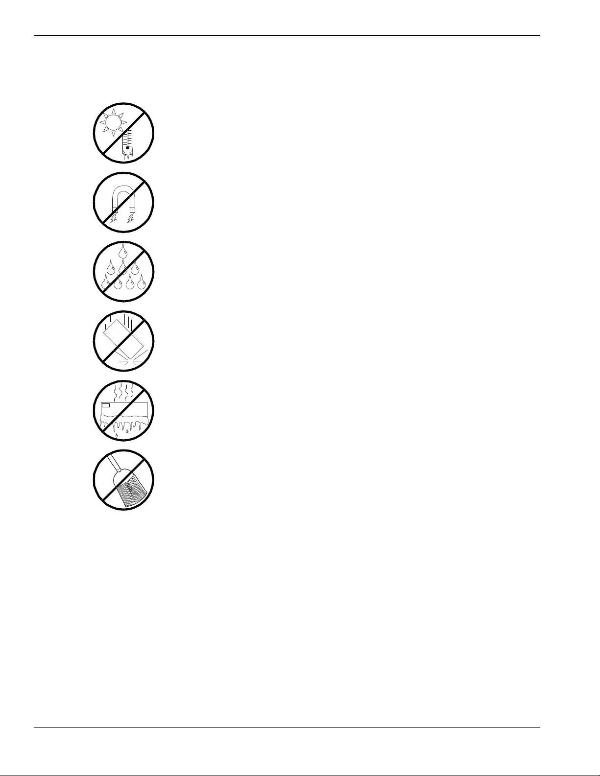
Use the following guidelines to pro p er ly handle and care for your syste m.
Protect the system from extremely low or h igh
temperatures. Let the system warm (or cool)
to room temperature before using it.
Keep the system away from magnetic forces.
Keep th e system dry. Do n ot wash the
system with a wet cloth or pour fluid
into it.
Prot ect t he s ystem from bein g bum ped or
dropped.
Check the system for con densa tion . If
condensation exists, allow it to evaporate
before powering on the system.
Keep th e system away fr om dust , sand,
and dirt.
xii Using This Guide
Page 15

System Overview
Overview
Chassis
System Board Features
Peripheral Devic es
System Power
Software Locks via the BIOS Set up
Disk Array
Hot Swapping
1
Hot Plug PCI
Degradation
AC Linkage Mode
Sleep Mode
System Functions
Page 16

Overview
The server is a modular, multiprocessing server based on the Int el Pentium® III
Xeon™ processor chip set. The chip set inco r po r ates a modular sca lea ble
architecture that integrates a 64-bit bus interface with three Peripheral
Component Interconnect (PCI) buses and an Industry Standard Architecture
(ISA) bus. The architecture supports Symmetrical Multiprocessing (SMP) and a
variety of operating systems. The chassis and system boards are designed to
meet the needs of the server marketplace.
The combination of comput ing performance, memory capacity, and integrated
I/O provides a high performance environment for many applications including
network servers and multi-user systems. The server is designed for use in
applications where downtime must be minimized. To this end, the server
includes or has the option to include the following.
All systems are configured with an addit ional redundant po wer supply.
The redundant power supply system will continue to operate in the event
of a single power supply failure.
Hot-swap self-contained power supply units that can be easily installed or
removed from the back of the chassis.
Hot-swap Ultra2-wide SCSI hard dr ive bays accessib le from the front of
the chassis where a failed drive can be removed, and a new drive insta lled
without system power being turned off.
High degree of SCSI hard disk fault tolerance and advanced disk array
management features through the use of RAID (Redundant Array of
Independent Disks) technology.
Cooling system redundancy w here the system will continue to o perate in
the event of a fan failure or having cabinet temperatures approaching the
threshold limit, the redundant fans will switch to maximum operating
speed.
Hardware monitors (temperature and voltage) and software monitors to
indicate failure s.
Easy access to all part s for service.
1-2 System Overview
Page 17

System Feature Summary
A summary of the system features is included in Table 1-1.
Table 1-1. System Features
Feature Description
Modular board set System is intended for use with a modular board set based on Pentium III
Xeon processor technology; from one to eight 500 MHz processors and up
to 8 GB of memory.
Add-in board support System I/O board supports up to 8 add-in boards (seven PCI boards,
including four slots supporting 64-bit PCI boards, and one ISA board slot.
The Hot Plug PCI* board plugs into the System I/O board, supporting up to
four Hot Plug 32-bit PCI board slots.
3 1/2-inch diskette drive 3 1/2-inch diskette drive is externally accessible.
One locatio n f or a 3 1/ 2-inch
removable media device
5 1/4-inch SCSI CD-ROM 5 1/4-inch CD-ROM drive is externally accessible.
Three locations f or 5 1/4 -
inch removable media
devices
12 locat ions f or 3 1/2-inc h
Ultra2-wide SCSI-2 hard
drives
Hot swap-capable
backplane
Power supply Four 560-Watt autoranging power supplies are easily removed/installed for
Software: utilities , setu p BIOS Set up and Sy mbios Configuration Utility. The E
Security Mechanical: Key lock at the front door. One intrus ion sensor fo r front door to
One extern ally accessi ble 3 1/2-inch ha lf- height bay is avai lable for server
expansion.
Three externally accessible 5 1/4-inch half-height bays are available for
server expansion (diskette, CD-ROM, and/or tape drives).
Three hard disk drive cages; each holding up to four 3 1/2-inch hot-
swappable Ultra2-wide SCSI-2 hard drives. Each cage is secured behind a
metal EMI door; drives can be swapped in or out of the system without
powering it down. T he arr ay of drives allows eas y setu p of RAID
applications.
A hot swap-capable backplane is part of each drive cage assembly for SCSI
hard drives. The backplane is designed for Ultra2-wide SCSI-2 devices that
use the industry standard 80-pin Single Connector Attach (SCA) connector.
The backplane consists of a row of four drive connectors.
service. The fourth supply is redundant.
XPRESSBUILDER
ROM contains the setup utilities and drivers. The ESMPRO CD-ROM
contains the server manage ment softwa re .
secure diskette, hard disk, removable media device, power on/off switch,
reset switch, top cover, and left/right panel access. Three power inter-lock
sensors one on each side of the chassis and one on top of the chassis.
BIOS: Password enable.
CD-
*The Hot Plug PCI feature is currently not useable on the syst em, until Operating System support is available.
System Overview 1-3
Page 18

Expanding the Server as Needs Grow
A typica l minimum system configuration may include the following:
Board s et consisting of system I /O bo a rd, CPU basebo a rd with one
500 MHz Pentium
containing 256 MB of memory
Diskette drive and SCSI CD-ROM drive
Three SCSI hard drive cages with one hard drive and a RAID contro ller
installed
Integrated LAN controller
Four 560 watt power supplies (the fourth power supply provides
redundant power)
Onboard 2 MB video memory
System I/O bo ard ha s one I SA slo t and s even P C I slo ts fo r add -in boards.
The Hot Plug PCI board also plugs into the system I/O board, supporting
up to four Hot Plug PCI board slots. The system I/O board has a riser
board for external I/O (serial, parallel, video, SCSI, USB, LAN,
keyboard, and mouse) interfaces.
III
Xeon™ processo r, and o ne memory board
Chassis can hold six removable media dr ives: four 5 1/4-inch half-height
bays with a CD-ROM drive installed in one bay; and two 3 1/2-inch halfheight bays w ith a dis ket te dr ive installed.
As server/client needs grow, you can expand system processor capacity,
memory, drives, option boards, and the number of power supplies.
CPU backboard has four s lots for CPUs, for a configurable range of one,
two, three, or four processors.
Two memory boards support 32 DIMM devices, t hat is16 DIMM devices
per board, for up to a maximum memory size of 8 GB of memory.
System I/O bo ard ha s twe lve o ption board slo ts (eleve n PCI a nd one ISA
slot).
Chas sis can hold six r emo vable media dr ives.
Three SCSI hard drive cages support up to 12 hot-swap bays for
3 1/2-inch Ultra2-wide SCSI-2 hard drives.
Confi gur a tion Cons tr ai nt s
The system has four 5 1/4-inch half-he ig ht ba ys access ib le fro m the front . These
bays are convenient for diskette, tape, and CD-ROM drives (removable media).
Because of the EMI generated by hard drives, the increased susceptibility to
ESD, and cooling requirements, hard drives should not be insta lled in the 5 1/4inch half- he ig ht bays.
1-4 System Overview
Page 19
Chassis
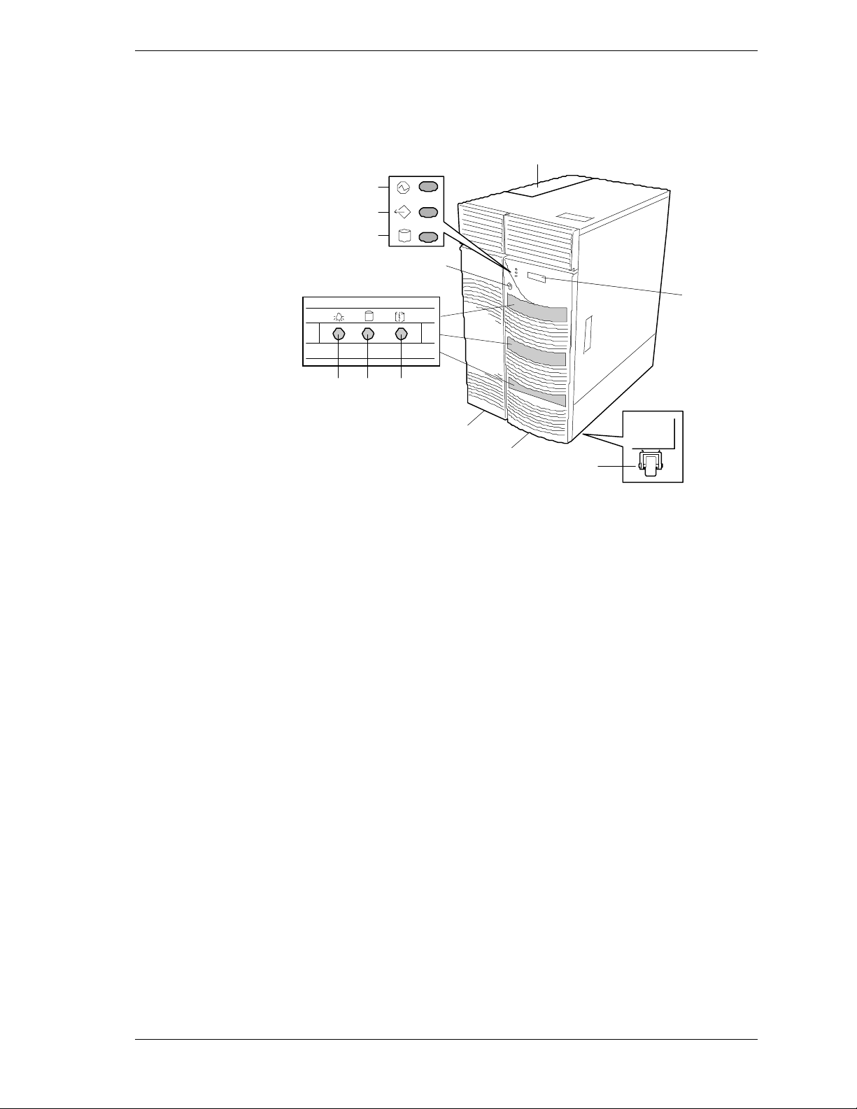
Figure 1-1 shows the server fro nt chassis features and controls.
A
B
C
D
E
F
3
GH I
J
K
L
A
Hot Plug PCI slots Four 32 bit hot-swappable PCI slots.
B
Power LED When green, power i s present in syst em . When off, power i s
turned off, power source is disrupted, or system is in the
sleep mode. See Table 1-2 for a list and description of the
system LEDs.
C
Status LED When green the system is O K. See Table 1-2 fo r a list and
description of the system LEDs.
D
Disk LED When green, internal disk drives are being accessed. See
Table 1-2 for a list and description of the system LEDs.
E
Key lock Secures both front external doors.
F
LCD panel Displays information about BIOS and system failures (error
and diagnostic information).
G
Drive pr esent
H
Drive acti vi ty
I
Drive st atus
J
Left front door Used when accessing a 5 1/4-inch device.
K
Right front door Used to access the power switch, sleep switch, floppy disk
L
Casters (4) Used when moving the server. Fixed by the caster holders.
Each drive has three LEDs visible above the bay from the
front. See Table 1-3 for a list of SCSI disk drive status LED
indicators.
drive, or a hard disk drive in a 3 1/2-inch device bay.
Figure 1-1. Front Chassis Features and Controls
System Overview 1-5
Page 20

Status LED In dicator Descr iptions
Table 1-2 lists the system status LED indicators along with a description of each
LED indicator. Table 1-3 lists the disk drive status LED panel indicators along
with a description of each LED indicator. Table 1-4 lists system status abnormal
conditions.
Table 1-2. System Status LED Indicators
LED Status Description Response
Power Off Power OFF None required (normal)
Green Power ON None required (normal)
Amber System power
supply failure or in
sleep mode
Status Off Power OFF None required (normal)
Green No alarms None required (normal)
Amber Abnormal condition
(see Table 1- 4)
Disk Off Not accessing disk
drives
Amber Internal disk drive
failure
Green Accessing disk
drives
Replace failed power supply
module or check to see if the
system is in sleep mode.
Check condition
None required (normal)
Check disk drive status LEDs
None required (normal)
Table 1-3. Disk Drive Status LED Panel Indicators
LED Status Description Response
Disk Drive
Present
Off Disk drive not
present
None required (normal)
Disk Drive
Activity
Disk Drive
Status
1-6 System Overview
Green Di sk drive present None required (normal)
Off Not accessing disk
drive
Green Accessing disk drive None required (normal)
Off No alarms None required (normal)
Amber
(Steady light)
(Flashing light)
Disk drive failure
Rebuilding data (in
disk array
configuration only)
None required (normal)
Replace disk drive
None required (normal)
Page 21
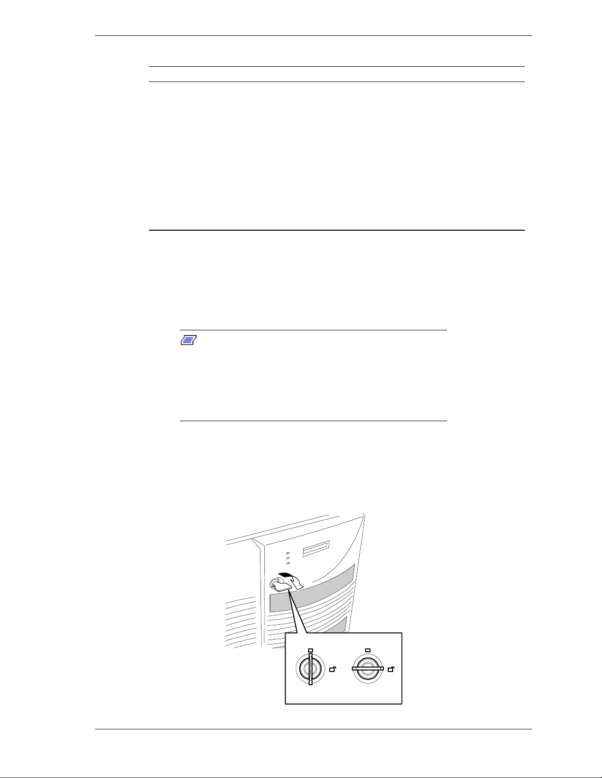
Table 1-4. System Status Abnormal Conditions
LED (Amber) Conditions
System Status Chassis intrusion (front cover)
Opening the Front Doors
You must open the right front door to turn the server power on or off, place the
server in sleep mode, mount or dismount a floppy disk, or mount or dismount a
hard disk drive. Open the left front door to mount or dismount 5 1/4-inch
removable media devices.
Unit fan alarm
Memory multi-bit error (SERR)
P6 bus error (SERR)
Thermal sensor
Temperatur e
Voltage
CPU thermal trip
PCI PERR# (OPB/ESC detect)
PCI SERR#
CPU internal error
WDT
IOCHK
Some options for the 5 1/4-inch dev ic es such as a
Note:
CD-ROM drive have a functi on to eject a tray or media using
a software command. B efore issuing a software command to
eject a tray or media, confirm that the front door is open. If
the command is executed while the front door is closed a
tray or media may run into the front door r esul ting in an error
or may cause the unit to fail.
Open the front doo rs as follows.
To open the front doors, you need to use the securit y key provided with the
1.
server. Insert the secur it y key into t he key slot and turn the key to the right
(see the following figure).
LOCK
UNLOCK
System Overview 1-7
Page 22
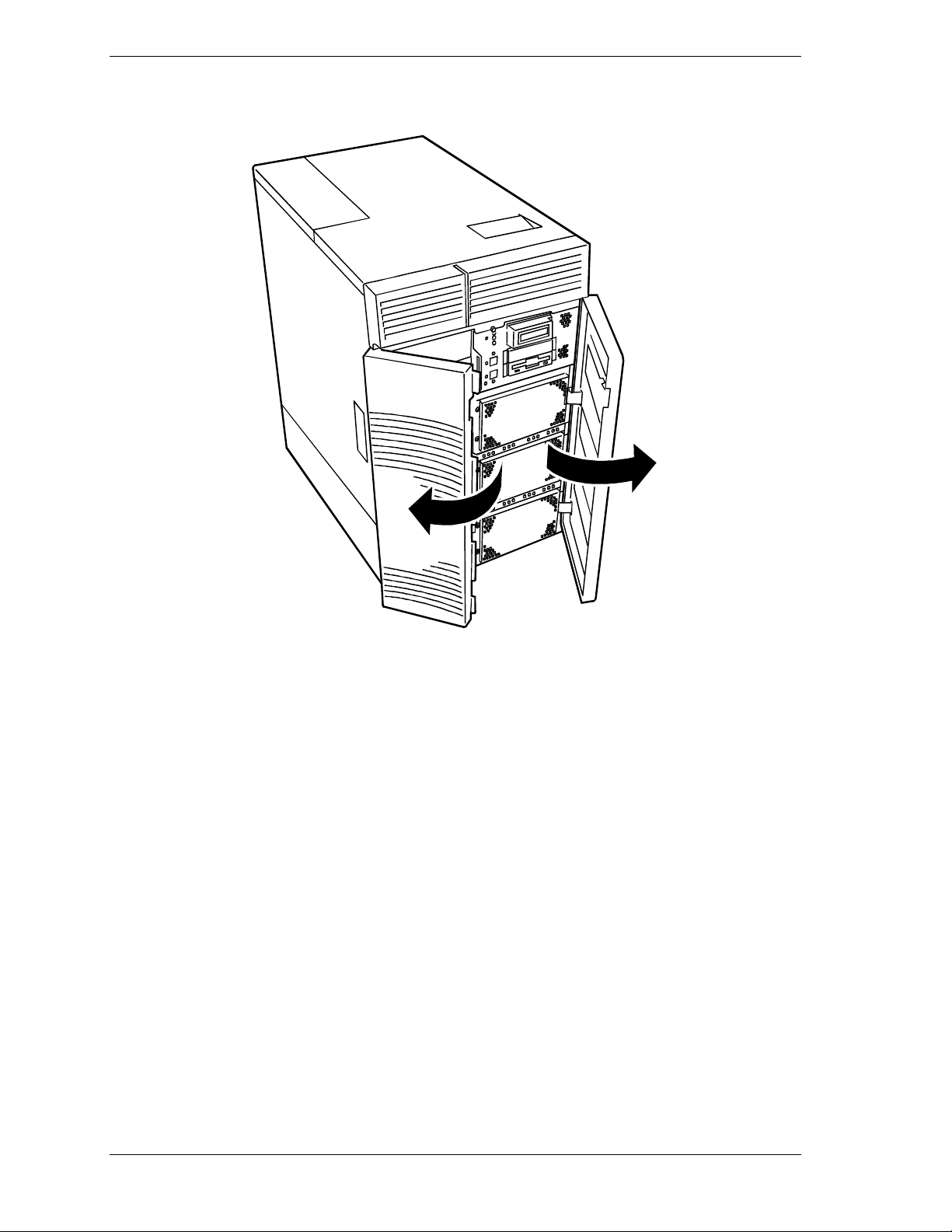
2. First open the right front door, then open the left door (see the following
figure).
1-8 System Overview
Page 23
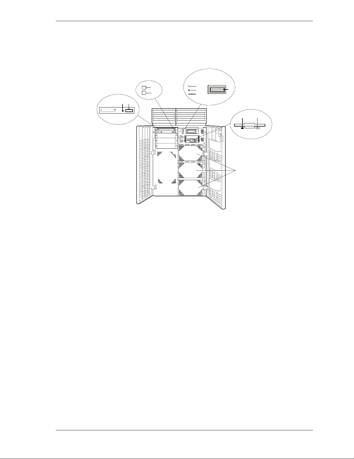
Chassis Fea tures and Con tr ol s
Figure 1-2 shows the server fro nt chassis features and controls. Figure 1-3
shows the server rear chassis features and co nt rols.
H
I
JK
SCSI hard drive cages (3) Each cage contains four disk drives. Above each drive are three status
A
Ejector but t on, 3 1/2-inch dis k ett e
B
drive
Activity light, 3 1/2-inch diskette
C
drive
LEDs. Refer to Table 1-3 for information on disk drive status LEDs.
Press to eject diskette.
When lit, driv e is in use.
E
F
G
D
BC
A
LCD panel Displays information about BIOS and system failures (error and diagnostic
D
Power LED When green, power is present in system. When off, power is turned off or
E
Status LED When green the system is OK. See Table 1-2 for a list and description of
F
Disk LED When green, intern al dis k drives are bei ng accessed. See Table 1-2 for a
G
DC power switch Press to turn system DC power on or off.
H
Sleep switch Press to enter power saving (sleep) mode. Press again to enter normal
I
Load/ej ec t button, CD- R OM drive.
J
(Note that the front controls may
vary per model of CD-ROM drive.)
Activity light, CD-ROM drive. (Note
K
that the status indicators may vary
per model of CD-ROM drive. )
information).
power sour ce is disrup t ed. See Table 1- 2 f or a lis t and desc ription of t h e
system LED indi cators.
the syst em LED in dicators.
list and description of the system LED indicators.
mode of op eration. This f u nc ti on r eq ui res a corres p on di ng operating
system.
Press to load CD and eject CD.
When lit, driv e is in use.
Figure 1-2. Front Chassis Features and Controls (front doors opened)
System Overview 1-9
Page 24
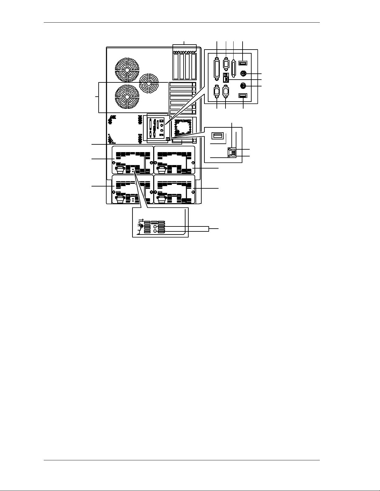
BC
ADEFG
H
IJ
K
LMNG
A
Hot Plug PCI
slots
Q
R
R
R
R
S
Four Hot Plug PCI add-in board slot locations (PCI #21, PCI #22, PCI #23, and
PCI #24). Hot Plug PCI slot functionality depends on the type of operating
O
P
system support. Please note that without PCI Hot Plug operating system
support you cannot replace PCI boards while the server is powered on.
B
PCI slots Three PCI add-in board slot locations (PCI #11, PCI #12, and PCI #13).
C
PCI slots Four 64-bit add-in board slot locations (PCI #31, PCI #32, PCI #33, and PCI
#34).
D
Printer LPT1 25-pin parallel port connector.
E
Monitor VGA monitor 15-p in conne cto r.
F
External-SCSI Narrow-SCSI 50-pin connector.
G
USB USB Interface connector. Appropriate driver is required.
H
Keyboard PS/2-compatible 6-pin mini-DIN conne cto r.
I
Function select
See
switches
J
Reset button Press to reset system or execute a memory dump. The reset function and
dump function can be switched by setting the function select switches.
K
Mouse PS/2-compatible 6-pin mini-DIN connecto r.
L
COM1 COM1 serial port 9-pin connector.
M
COM2 COM2 serial port 9-pin connector.
1-10 System Overview
Configuring Switch and Jumper Settings
in Chapter 4 of this Us er’s G uide.
Page 25

N LAN 100Base-TX network LAN connector.
O Status LED Lit when system is connected to a LAN Network with a 10Base-T cable. When
connected with a 100Base-TX cable, it does not light.
P Active LED Lit when information packets are exchanged between the system and the
network.
Q ISA slot One ISA add-in board slot location.
R Power supplies Four power supplies (one redundant). Each power supply has a separate AC
input power connector.
Power status
S
LEDs
Both indicators are green during normal operation. Either or both indicators go
off when power supply fails. See Table 1-2 for status descriptions.
Figure 1-3. Rear Chassis Features and Controls
System Overview 1-11
Page 26
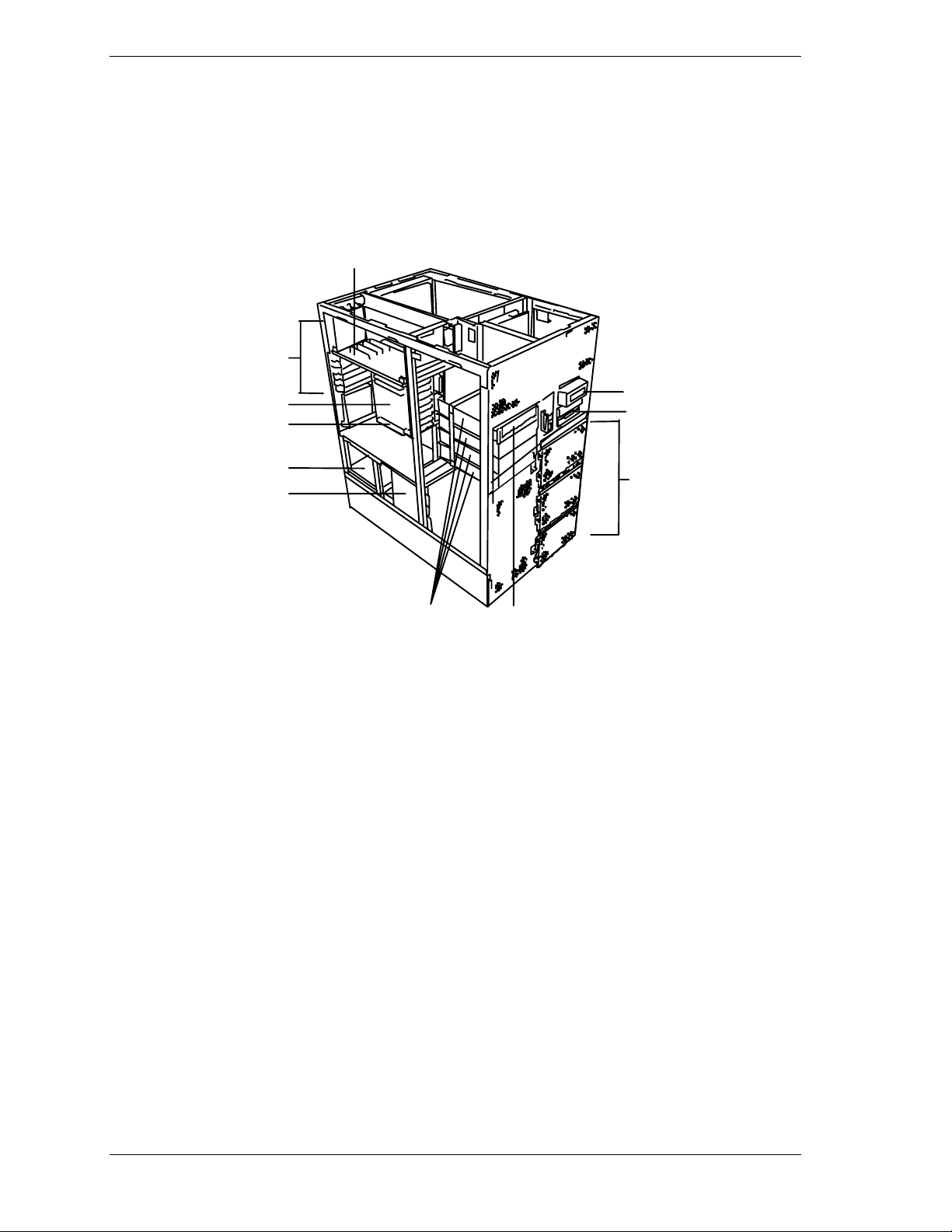
System Board Features
The board set includes the Hot Plug PCI board, system I/O board, base board,
CPU backboard, and a memory board. The system I/O board is mounted
vertically on the left side of the system. Figure 1-4 shows the system with the
left side cover removed.
A
B
C
D
E
F
GK
A Hot Plug PCI board
B Expansion slot covers
C System I/O board
D Additional ISA slot
E Power unit
F Power backplane
G Four 5 1/4-inch half-height bays with a CD-ROM
drive installed in bottom bay
H
I
J
H Liquid crystal display (LCD)
I Diskette drive
J Hard disk drive bays
K CD-ROM drive (standar d)
1-12 System Overview
Figure 1-4. System I/O Board Location
Page 27
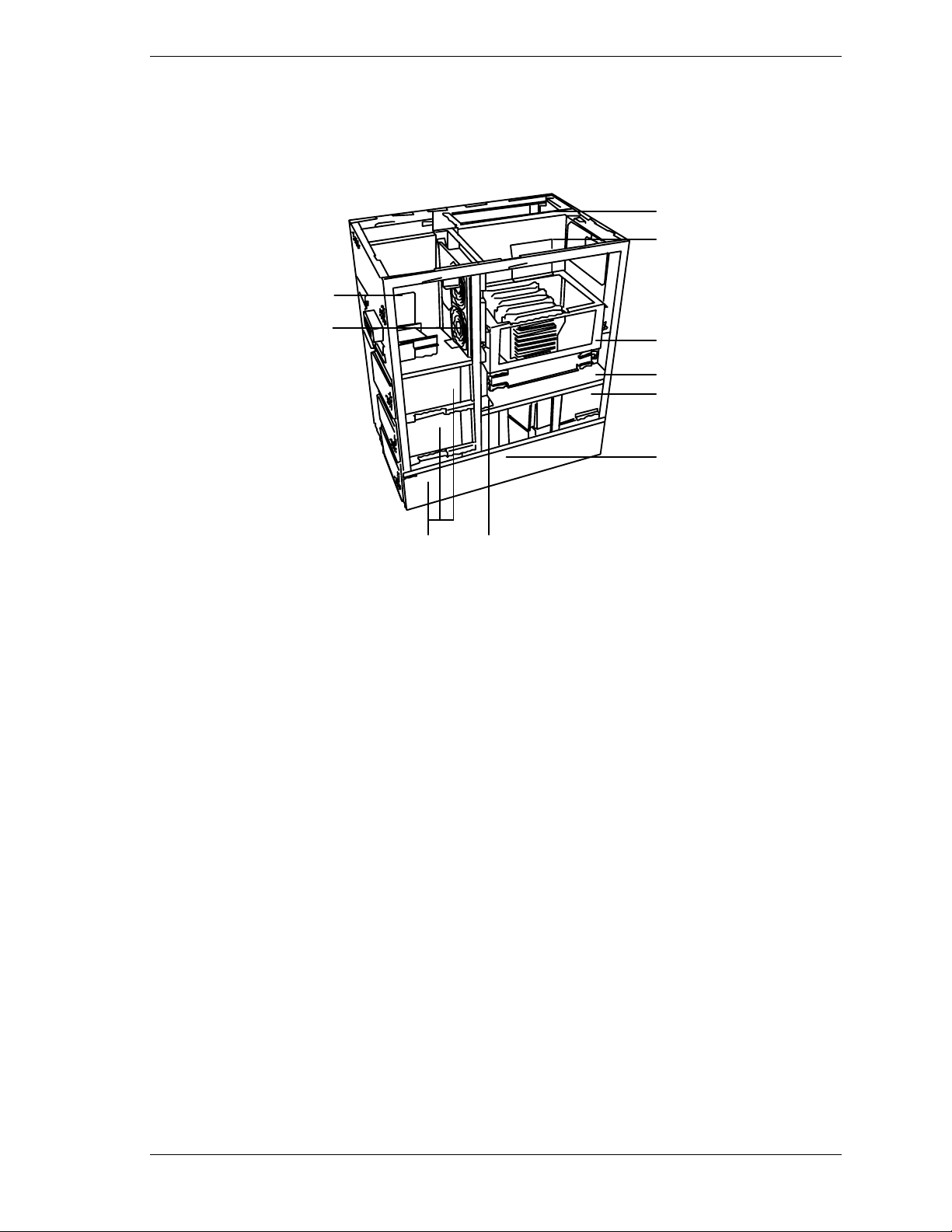
The Hot Plug PCI board plugs into the left side of the system I/O. The base
board plugs into the right side o f the syst em I/O board and the CPU backboards
and memory boards plug into the base board. Figure 1-5 shows the system with
the right side cover removed.
A
B
G
H
IH
A
Base board
B
Termin ator board
C
CPU backboard (supports 1 - 4 Pentium III
Xeon processors with associated VRMs)
D
Memory b oa rd
E
Power unit
F
Power back panel #1
C
D
E
F
G
Front panel board
H
Cooling fans (upper 2 for the CPU, lower
two for the memory boards)
I
Har d disk dr ive b ays
Figure 1-5. Base Board, Terminator Board, CPU Backboard, and Memory Board
Location
System Overview 1-13
Page 28

Figures 1-6, 1-7, 1-8, 1-9, and 1-10 show the major components on the Hot Plug
PCI board, system I/O board, base board, CP U backboard, and memor y board.
Table 1-5 summarizes the featur es of the board set.
Table 1-5. Features of the Board Set
Feature Descri ption
Hot Plug PCI slots Four Hot Plug PCI add-in board slot locations.
Multiple processor
slots
Upgradable
memory
Add-in board
support
SCSI controller Single onboard SCSI-2 controller (PCI-based).
BIOS Flash memory-based BIOS (Basic Input/Output System ) and Setup
Video Integrated super VGA controller ships with 2 MB of video memory.
External device
connectors
Clock Real-time clock/calendar (RTC).
System hardware
monitoring
Configuration
utilities
Four processor sockets on each of the two CPU backboards.
Sixteen DIMM sockets on each of the two memory boards, supporting
up to 8 GB memory using 256 MB DIMMs.
One ISA bus slot, four dedicated 64-bit PCI bus slots and seven 32-bit
PCI bus slots on the system I/O board and Hot Plug PCI board.
utilities.
Onboard connectors for two serial ports, parallel printer port, narrow
SCSI port, two USB connectors, 100Base-TX connector, PS/2compatible keyboard and mouse, and VGA monitor.
Detects chassis intrusion and contains sensors for temperature,
voltage, and fan failure.
BIOS Setup and Symbios Configuration Utility.
1-14 System Overview
Page 29

A
B
A
Second PCI board slot (PCI #21, PCI #22, PCI #23, and PCI #24)
B
LED switch board connector
Figure 1-6. Hot Plug PCI Board Connector and Component Locations
System Overview 1-15
Page 30
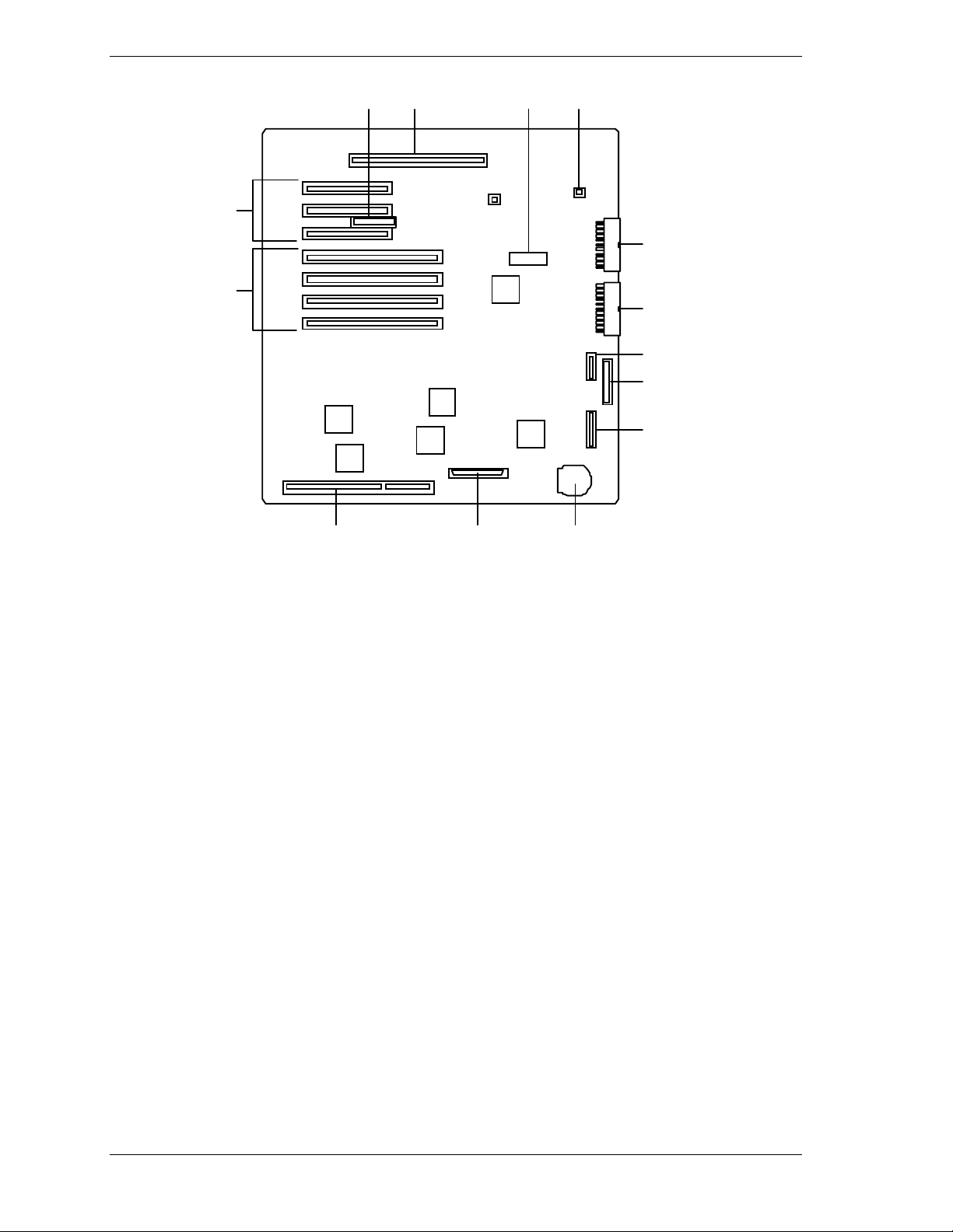
AB C D
E
G
F
H
I
J
K
LMN
A
Server management board connector
B
Hot Plug PCI board connector
C
Non-volatile Memory (NVRAM) with built-in lithium battery
D
Fan connector
E
First PCI board slots (32-bit) (PCI #11, PCI #12 and PCI#13
fr om the bottom).
F
Third PCI slots (64-bit) (PCI #31, PCI #32, PCI #33 and PCI
#34 from the bottom). The first disk array controller must be
mounted in PCI #32 then subsequent disk array controllers are
mounted in sequence (PCI #33, PCI #34, etc.)
G
Power connector 2
H
Power connector 1
I
Front panel connector
J
Floppy disk drive connector
K
Power backplane connector
L
ISA board slot
M
First SCSI-2 connector
N
Battery (lithium)
Figure 1-7. System I/O Board Connector and Component Locations
1-16 System Overview
Page 31

A
B
C
D
EF
A
Fan connectors (fan connector #4, #5,
and #6 from the left).
B
CPU back board connector ( Opti onal ) .
When an optional CPU backboard is not
mounted, a terminator must be
connected.)
C
CPU backboard connector (Standard).
D
Fan connectors (fan connector #3, #2,
and #1 from the top).
E
Mem ory board c onnector #2
F
Mem ory board c onnector #1
Figure 1-8. Base Board Component Locations
System Overview 1-17
Page 32

A
Pentium III Xeon processor sockets
A
(1 - 4 from bottom)
VRM sockets (1 - 6 from bottom)
B
Figure 1-9. CPU Backboard Component Locations
B
B
D
F
H
A
C
E
G
A DIMM sockets (Bank #A, Slot 1 and Slot 3)
B DIMM sockets (Bank #A, Slot 2 and Slot 4)
C DIMM sockets (Bank #B, Slot 5 and Slot 7)
D DIMM sockets (Bank #B, Slot 6 and Slot 8)
E DIMM sockets (Bank #C, Slot 9 and Slot 11)
F DIMM sockets (Bank #C, Slot 10 and Slot 12)
G DI MM sockets (Bank #D, Slot 13 and Slot 15)
H DIMM sockets (Bank #D, Slot 14 and Slot 16)
Figure 1-10. Memory Board Component Locations
1-18 System Overview
Page 33

Processor
Each Pentium III Xeon processor is packaged in a single edge contact ( S.E. C. )
cartridge. The cartridge includes the processor core with an integrated 16 KB
primary (L1) cache; the seco ndary (L2) cache (1MB or 2MB); a thermal plate;
and a back cover. The cartridge is secured by a retention module attached to t he
CPU backboard. Depending on configuration, your system has one to eight
processo r s (see Figure 1-9). Addit ional processo r s enhance per formance and
enable symmetric multiprocessing (SMP ) . All processors access the same
memory and I/O space and tasks can run on either CPU if your operating system
(OS) supports SMP.
Memory
The system supports a maximum of two memor y boards. Each memory board
contains sixteen 168-pin DIMM sockets (see Figure 1-10). A minimum system
configuration includes 256 MB (using four 64 MB DIMMs) of system memory.
Sixteen DIMM sockets on each memory board allow for syst em memory
expansion up to 8 GB (using a total of thirty two 256 MB DIMMs on two
memory boards.) E CC generat ion/checking is pro vided for detection and
corre c tio n o f memory err o rs.
Note:
Only use DIMMs approved for use in this server
system. Call your custom er service representative f or
information.
Bus Master I/O Expansion Slots
The server's expansio n capab il it ies meet t he needs o f high performance I/O
servers by providing a combination of PCI local bus and ISA connectors. The
system I/O board offers eleven dedicated PCI slots, four of which are 64-bit, and
one ISA slot. The ISA architecture supports 32-bit memory addressing and 16bit data transfers for t he CPU, DMA, and bus masters.
Real-Time Clock/Calendar
The real-time clock provides syste m clock/calendar information stored in a nonvolatile memory (NVRAM) (Figure 1-6, M). The real-time clock battery (see
Figure 1-6, G) provides power backup for the real-time clock.
BIOS
A BIOS and Setup Utility are located in the Flash memor y on the syst em I/O
board and include support for syste m setup and PCI/ISA Plug-and-Play auto configuration. A number of security, re liabilit y, and manageme nt featur es ar e
also incorporated to meet vita l server needs.
System Overview 1-19
Page 34

Video
The onboard super VGA controller (PCI ) is a high-perfor mance SVGA
subsystem that supports:
BIOS compatibility with VGA, EGA, CGA, Hercules Graphics, and
MDA
2 MB of Video Memory
16-bit bus for high-speed displa y memor y access
Hardware accelerated bit block transfers ( BIT BLT )
72Hz refresh, non-interlaced at: 640x480, 800x600, or 1280x1024
resolutions
Up to 16M colors at 640x480 and 800x600 resolutions, 64K colors at
1024x768 resolutions and 256 colors at 1280x1024 resolutions with the
optional 2 MB video memory.
performance video modes.
SCSI Controller
SVGA drivers may be required to use the hi gh-
Note:
The system I/O board includes a single U ltra2- wide SCSI-2 controller (LSI
Logic SYM53C875) integrated as a PCI bus master. This controller supports
data paths of 8-bit (fast/narrow SCSI) at a data transfer rate of 10 MB/sec and
16-bit (fast/wide or ultra /wide SCSI) at a data transfer rate of 20 MB/sec or 40
MB/sec. As a PCI bus master, this controller supports burst data transfer rates
up to the maximum of 133 MB/sec.
Peripher al C o ntroller
The advanced integrated peripheral contro ller supports two serial ports and one
parallel port through the I/O riser board (see Figure 1-6, A). The advanced
integrated peripheral controller also supports the connection of two diskett e
drives (see Figure 1-6, I).
External Device Connectors
The I/O panel provides connector s for a PS/2 compatible mouse and a keyboard,
connectors for VGA monitor, two serial port connect ors, parallel printer port
connector, and a USB interface co nnect or. It also provides a narrow SCSI
external connector.
Keybo ar d an d Mo us e
The keyboard/mouse cont ro ller is PS/2-co mpat ible.
1-20 System Overview
Page 35

Fans
In addition to the power supply fans, the system has an option board fan cabled
to the I/O board, six CPU fans cabled to t he base boar d, and two memor y board
fans cabled to the power backpanel #1. The three CPU fans (front and rear) are
redundant in configuration. If one fan fa ils, its associated fan changes its
rotating speed to high.
Peripheral Devices
The following paragraphs describe the Ultra2-wide SCSI-2 hard drive bays and
5 1/4-inch removable media drive bays.
Ultra2-Wide SCSI-2 Hard Drive Bays
The right side of the system contains up to three Ultra2-wide SCSI hard drive
cages for 3 1/2-inch SCSI-2 hard drives (see Figure 1-9). Each hard drive cage
has a hot-swap backplane that supports four drives. The backplanes require an
80-pin single connector att achment (S CA) co nnector o n the drives you install.
A drive carrier is required as part of the hot swap implementation. A 3 1/2-inch
peripheral between 1.0 and 1.6 inches high can be accommodated in each
carrier. A drive is mounted in the carrier with four screws, and t he carrier is
retained in the chassis by a locking handle.
A fault light on the front panel board g ives a genera l indication that there has
been a fault on a hot-swap drive as detected by the RAID controller. Each dr ive
has a set of three lights to indicate the fault or other status: power-on (green
LED), activity (green LED), or fault (yellow LED).
Three hard drive cages
(EMI panel and exterior door
shown open)
Figure 1-9. Ultra2-Wide SCSI-2 Hard Drive Bays
System Overview 1-21
Page 36

The backplane has two main functions: SCSI drive control and system dat a
logging. Drive status is monitored to detect failing drives and to control LED
indicator s. T he backplane features include the following:
Insertion and removal of hard drives while power is on (referred to as
“hot swap”)
Simplif ie d cable management
SCA connectors to simplify inserting and removing hard drives
SCSI management of fault LEDs.
Each backplane supports SCSI drives with SCA connectors.
Removable Media Drive Bays
On the upper left side of the system, four 5 1/4-inch half-height bays (see
Figure 1-10) are designed for peripherals with removable media (diskette, CDROM, tape). Two available adjacent 5 1/4-inch bays can be converted to a
single full-height bay. The 5 1/4- inch drives can be removed directly from the
front of the chassis. Remova l o f the syst em top cover may be required to
install/remove t he device cab les. C osmetic fi ller p anel is installed over all
unused 5 1/4-inch bays.
Factory-installed CD-ROM reader plus
three bays for remo vable media drives.
Factory-installed 3 1/2-inch diskette drive
plus second bays for removable 3 1/2-inch
drive.
(Exterior doors shown open)
Figure 1-10. Removable Media Drive Bays
On the upper right side of the system, below t he LCD panel, are two built-in
3 1/2-inch bays. One contains a 3 1/2-inch diskett e drive that supports both 720
KB and 1.44 MB media (see Figure 1-10).
Note:
the last SCSI drive of the dai sy chain cabling (bottom media
bay). All other dev ic es must have terminators removed.
1-22 System Overview
The SCSI terminati on r esi stor s must be installed in
Page 37

System Power
The system may be configured with up to four 560-Watt power supplies. Each
supply automatically switche s between these input voltage ranges:
100-125 VAC at 50/60 Hz; 10.5 A maximum current
200-240 VAC at 50/60 Hz; 5.5 A maximum current
Each power supply provides DC outputs of +5 V, +12 V, +3.3 V, -5 V, and
-12 V. All output grounds connect to the power supply chassis and to earth
ground through the AC line cord. Each supply has:
Individual AC input line cord that plugs into the external side of the
power supply
Isolating device on each DC output so that t he failure of one supply does
not affect the operation of the others
Cooling fan integral with each power supply enclosure. The fan circuit
implements fan failure detect ion.
In a system, power is drawn equally from all supplies installed. A system with
three power supplies can be fully loaded (a ll drive bays and add-in board slots
filled). The supp lies use a forced cur r ent - shar ing technique t hat ensures the
supplies share within 10 percent at full load. In a high-access system with four
power supplies, the fourth supp ly gives redundancy, becau se the load is
redistributed if one supply fails.
Software Locks via the BIOS Setup
The BIOS Setup has software feat ur es t hat let you cont rol access to one or more
parts o f the s ystem:
Set and enable an administrative password
Set and enable a user password
Enable password on boot
Disable writing to the diskette drive when secure mode is set.
If only a supervisor password is set and enabled, enter this password to boot the
server.
If both the user and administrative passwords are set and enabled, enter either
one to boot the server. Enter t he ad ministrative password to access t he BIOS
Setup to change the system configurat ion.
System Overview 1-23
Page 38

Disk Array
The hard disk drive bays of the server support disk array configuration RAID
levels 0, 1, 5 and 6.
RAID is an acronym of “Redundant Arrays of Inexpensive (Independent)
Disks”. It logically integrates severa l hard disks to appear to the syste m as only
one disk drive.
Using the disk array method, the large-capacity hard disk can be configured
with several inexpe nsive a nd smal l-capac ity hard disks. It can also enhance the
drive by improving the reliability and supporting an auto matic rebuilding
function.
All RAID levels are common in their basic o per ation due the fact that several
hard disks can be recognized as one d isk drive. Ho wever, performance, cost, and
use are conditions that var y accord ing to the RAID le vel. Yo u should select an
appropriate configuration that is suitable for your system.
Features and select ion examp les of different RAID levels are shown below.
Level Definition Redund-
ancy
RAID0 Striping No Access: high-speed.
RAID1 Mirroring
(or shadowing)
RAID5
Striped data
and parity
Yes Dual disk syste m.
Yes Parity data.
Feature Sui t able
Improves reliability.
Read mode: highspeed
Write mode: slow
speed
Trans fers large
amount of data.
Access: slow
application
Application that
needs high
performance for
non-critical data
Application that
needs to store
important files
on ma in syst em
drive
Application that
needs high
speed transfer
rate.
Application of
read-intensive
type
data searching.
Minimum
No. of di sks
2
2
3
This unit supports other RAID levels as well. However, it is not recommended
to use them unless a bsolutely necessar y.
In RAID0, the well-balanced access over all the hard disks can impro ve
reliability compared with the single-unit hard disk, which frequently accesses
only one hard disk.
In RAID1, high-reliability can be realized by the better utilization of disk data.
Also, select ing a disk that can read data faster t han ot hers ga ins high
accessibility.
1-24 System Overview
Page 39

In RAID 5 and RAID 0, the transfer data size becomes extremely large due to
striping struct ur e. T herefore, t hey are suita b le for applications that handle largesized files such as dat a ret r ieva l.
In RAID 1 and RAID 5, since the function to reconstruct lost data due to hard
disk failure is part of the op eration, a larger number of hard disks are required
compared with RAID 0 or when the disk array is not used.
For example, to configure a disk drive that uses a 4 GB hard disk with an user
area of 8 GB, two hard disks are all that is needed for RAID 0 and RAID 7
(non-disk array system). In RAID 1, four disks (two primary and two mirroring
disks) are required. In RAID 5, three disks (two primary disks and one
redundant disk) are required.
Hot Swapping
Hot swapping allows a device to be replaced, such as a hard disk drive while its
power is o n, as listed be low.
Disk arra y system:
Any failed hard disk drive can be replaced while the system is running.
Power redundant system:
When four power supplies are installed a failed power supply can be
replaced by hot swapping.
Note:
Hot Plug PCI
Hot Plug PCI bus slots (for the secondar y PCI bus) ar e located under the top
cover of the server (see Figure 1-4) . T h is PCI bus allows devices t o be installed
or removed while the server is powered on (if the operating system supports the
Hot Plug PCI function.)
Note:
PCI function.
Note:
Plug PCI access cover can not open.
The fourth power supply is always the redundant.
Windows NT 4.0 does not support the Hot Plug
Your server may be configured so that the Hot
System Overview 1-25
Page 40

Degradation
If a CPU or a memory DIMM board error was detected during execution of
POST (Power On Self-Test) after syst em power is turned on, the degradation
function isolat es the failed CPU o r memory DIMM bo ar d and co nt inues
operation. Yo u shou ld replace the failed device as so on as possible.
This function is enabled only when the following sys te m requirements are met:
Two or more C PUs are installe d .
Two CPU backboards (Tertiary cache) are installed
Eight memory DIMM boards are installed.
A CPU or memory DIMM board er ror may be viewed on the scree n while
POST is running or by entering BIOS Setup." It may also be viewed when the
ESM PRO progr a m is installed and o pera ting.
AC Linkage Mode
When the power cord of the server is connected to an uninterruptible power
supply (UPS) unit, the server supports the power linkage function. This function
controls the server power from the UPS. This mode can be switched by using
the control switch on t he rear pane l.
Sleep Mode
The SLEEP mode switch on the front of the server is used for saving power .
If the SLEEP mode switch is pressed, then the server enters into the sleep st ate
(the Drive Bay Pow e r lamp a nd the P ower lamp will blink simu ltaneously). In
the power saving mode, the memory data and the states of the jobs are kept
unchanged. In addition, the server in the power saving mode can accept access es
to hard disks from other machines on the network and perform other network
jobs.
Sleep mode requires an operating system that supports its function.
Note:
function.
Windows NT 4.0 does not support the Sleep m ode
1-26 System Overview
Page 41

System Functions
The following subsections describe select system functions.
Automatic Rebuilding Function
The server supports the disk array automatic rebuilding function for data
recovery.
The automatic rebuildi ng function supports a disk
Note:
array configurat ion of RAID levels, RAID1, RAID5 or RAID6.
Rebuilding is to regenerate all data fro m a failed disk to a replacement disk. A
rebuild is necessary after a failed disk drive is replaced with a new one.
In disk array configuration RAID levels, RAID1, RAID5, or RAID6 the failed
disk does not affect the operation. Ho wever, if another disk error occurs before
automatic rebuilding, the dat a may be destro yed. To prevent such an accident , it
will rebuild after the failed d isk has bee n replaced.
In a conventional server, the user must select and execute automat ic rebuilding
using various utilities. T he ser ver executes rebuilding automatically. Since the
server also supports hot-swapping function, the failed disk can be replaced while
the power is on.
If the disk a rra y monitoring ut ility is installed, you may enc ounter t he following
indication and activity. The auto matic rebuilding is succes sfully in progress
unless the disk error LE D on the disk, which you ran the automatic rebuilding
lights (amber). This indicates a disk drive failure before complet ion of the
rebuild.
The message “Rebui ld was ca nceled” appears on the screen during
rebuilding.
It may seem that r e bu ilding stops a moment and r estarts.
Observe the following when using an automatic rebuilding function.
Do not turn the power off. If power is turned off, automatic rebuilding
will not start.
Use an interval of 60 seconds or more bet w een mounting and
dismounting the hard disk drive.
If a hard disk is being rebuilt, do not replace the hard disk.
System Overview 1-27
Page 42

Expand Capacity Function
Disk pack capacity can be expanded by adding a disk drive while the system is
running. This function is only support ed if the server is in the disk array
configuration mode.
This function does not utilize operations such as data backup, pack
reconfiguration, initialization, restoring the data.
If a hard disk is added under the operation of the Global Arra y Manager,
perform the following.
After the hard disk is insta lled, wa it for abo ut 60 seconds and click t he
Scan Device key. Clicking the Scan Device key after the execution of the
expand array operation, w ill display the added disk co r rect ly.
If a hard disk is added to the system operat ing in RAID level 0, t he server is
changed to the RAID6 level. Only RAID6 is available for this system when
using the expand capacity function.
Remote Power-On (Wake On LAN) Function
The remote power-on function turns on the system power by way of a network
or modem. If the system power is set to Off, it can be turned on remotely by
sending a specific packet from the main computer to the remote system.
The standard default value of t he r em ote power-on
Note:
function is “Disabled” . To make it enabled, the Wake On
LAN item in the System Hardware m enu of t he Setup Utility
described in Chapter 6 “BIOS Configuration” must be
changed to “Enable.”
1-28 System Overview
Page 43

Setting Up Your System
Selecting a Site
Unpacking the System
Moving the System to the Site
Getting Familiar With the System
Making Connections
Connecting the Power Cords
Powering On Your System
2
Page 44

Selecting a Site
The system operates r eliably in a t ypical o ffice en vironme nt . Choo se a site that
meets the following requirements.
Site the system near grounded, three-pronged power outlets.
Note:
NEMA 5-15R outlets for 100-120 VAC or NEMA 6-15R
outlets for 200- 240 V A C. For ot her i nternational sites, this
means three-pronged power outlets applicable for the
electrical c ode of t he r egion.
Be sure the power service connec tion is through a properly
grounded outlet.
For the United States and Canada, this means
!
CAUTION
Each power cord can be plugged into a separate phase of a main AC
supply, assuming the circuit is rated for that load.
For Denmark, the system must be c onnec ted to an
Note:
AC power source rated at 16 amps.
Select a site that is clean, dust-free, and well vent ilated. Keep front and
rear ventilating op enings free o f obstr u ctions. Locate the system away
from sources of heat, vibration, or physical shock
Isolate the system from strong electromagnetic fields and electrical noise
produced by electrical devices (such as air cond it ioners, large fans, large
electric motors, radio and TV transmitters, and high-frequency security
devices)
The site should be spacious enough to provide at least s ix inches (15
centimeters) behind the system and on each side of the system for proper
cooling, airflow, and cable clearance.
Allow at least 11 inches (27 centimeters) in front o f the system for proper
front door clearance.
Position t he system for easy access for s ystem maintenance and
installation of system upgrades.
2-2 Setting Up Your System
Page 45

Unpacking the System
!
CAUTION
Your system weighs 165 pounds (75kg) or more with
optional equipm ent. To avoid personal injury, m ake sure you
have at least four person's help you lift or move the system.
When you receive your system, inspect the shipping co ntainers prior to
unpacking. If the shipping boxes are damaged, note the damage, and if possible,
photograph it for reference. After re moving the cont ent s of the containers, keep
the cartons and the packing materials. If the cont ent s appear damaged when you
unpack the boxes, file a damage claim with the carrier immediately. To unpack
your system, see the unpacking instr uctions on the shipping carton.
Moving the System to the Site
Once you have selected t he system installation site, move the server system as
follows.
1.
Casters are pro v ided on the botto m of the server. S low ly push the server t o
the selected installation locat ion.
!
CAUTION
For safety reasons, be sure to attach the caster holders on
the casters when the server is at the selected site.
2.
To secure the server so that it won't move, attach a caster holder (A) to each
of the server's casters as shown below.
A
Setting Up Your System 2-3
Page 46

Getting Familiar With the System
Before setting up your system, see System Overview in Chapter 1 of this User's
Guide to become familiar wit h t he syst em features, such as the location of your
system's security keylocks and front and rear panel switches, indicators and
connectors, etc.
Making Connections
Connect your keyboard, monitor, and mouse (see Figure 2-1). Connect any
external peripheral devices such as a printer or modem by following the
instruct ions included with t hese devices. To connect external SCSI cables, refer
to Cabling in Appendix A.
!
CAUTION
Damage to the system may resul t if the k ey boar d c able is
inserted or removed when power i s appl ied to the system.
!
CAUTION
Inserting a telephone line connector into a LAN board RJ- 45
port may result in personal injury and equipment damage.
2-4 Setting Up Your System
Page 47

B
A
C
D
E
F
G
2
1
Printer with parallel interface
A.
Monitor display unit
B.
External SCSI device*
C.
Device with USB interface such as a terminal adapter.
D
Requires NOS that supports the USB interface.
Keyboard
E
Mouse
F.
Device with USB interface such as a terminal adapter.
G.
Requires NOS that supports the USB interface.
H
I
J
Device with the serial interface such as a modem
H.
Hub (multi-port repeater)
I.
Network system on LAN (connected via a hub)
J.
* SCSI devices may be connected to connectors other than
the standard external SCSI connector.
Figure 2-1. Making Connections
Setting Up Your System 2-5
Page 48

Connecting the Power Cords
Plug the female end of each AC power cord into the input receptacles on the
rear of the power supplies (see Figure 2-2). Plug the male end of each power
cord into NEMA 5-15R outlet for 100-120 VAC or NEMA 6-15R outlet for
200-240 VAC. If the power cords supplied with the system are not compatible
with the AC wall outlet in your region, obtain a suitable power cord that meets
the following criteria.
The power cord must be rated for the available AC voltage and have a
current rating that is at least 125% of the current rat ing of the system.
The power cord connector that plugs into the wall outlet must be
terminated in a grounding-type male plug designed for use in your region.
It must have certification marks showing certification by an agency
acceptable in your region.
The power cord connector t hat plugs into the syst em must be a n IEC-
type CEE-22 female connector.
The power cord must be less than 1.8 meters (6.0 feet) long.
After connecting a power cord, make sure to secur e the cord with the tie-wrap
on the side of the power unit, so that the power cord is not accident ally pulled
out of its receptacle.
After the power cord is plugged in confirm that the two power status lamps on
the power unit are lit. If either or both lamps are off, a failure occurred in the
power unit, see System Status LED Indicators in Chapter 1 of this User's Guide.
When connecting the power cor d to a power contro l unit such as an UPS,
confirm that the power control unit is powered off. Connecting the power cord
while power is supplied to the power control unit may cause a failure.
To automatically turn on/off the system via the AC-LINK funct ion when a
power cord is connected to an UPS, follow the BIOS configurat ion inst r uctions
in Chapter 3 to change the internal settings of the server.
!
WARNING
Your system shipped with four AC power cords. Do not
attempt to modif y or use the supplied AC power cords if it is
not the exact type requi r ed.
2-6 Setting Up Your System
Page 49

Figure 2-2. Connecting the AC Power Cord
Setting Up Your System 2-7
Page 50

Powering On Your System
Power o n you r system as follows.
1. Make sure all external devices, such as a video display, keyboard, and
mouse (optional) have been connected, and t he power cor ds are connected.
2. Power on the video display and any other external devices.
3. Open the right front door and press the power on/off switch (B) on the front
panel (see Figure 2-3).
4. Verify that the Power LED (A) is lit. If it is not lit, ensure the AC power
cords are connected to functiona l AC power sources.
After a few seconds your s yst em begins the internal Power-O n Se lf Tests
(POST). POST automatically checks the system, CPU module, memory,
keyboard, and most installed peripheral devices. If you have problems powering
on your system, refer to Problem Solving in Chap ter 6.
A
B
A.
B.
2-8 Setting Up Your System
Power LED
Power ON/OFF Switch
Figure 2-3. Powering On Your System
Page 51

Configuring Your System
Configuring Your System
BIOS Setup Utility
Symbios Confi gurati on Utility
Configuring the RAID Controller
Configuring Syst em Jumpers and Switches
3
Page 52

Configuring Your System
Configuration and setup utilit ies are used to change your system configuration.
You can configure your system, as well as any option boards you may add to
your system, using the BIOS Setup (stored in the system FLASH memory). A
diskette is not needed to run BIOS S et up.
The Symbios Co nfiguration Utility st ore d in the s ys te m FLASH memory is u s e d
if you need to configure the SCSI controller in your system or to perform a
SCSI disk format or verify disk operation of these dr ives. A diskette is not
needed to run Symbios Configuration.
If your system has been factory configured, the BIOS Setup or Symbios
Configuration utilities do not need to be run unless you want to change the
password or security features, add option boards or devices, or upgrade the
boards in your system.
The following sections provide procedures for running the BIOS Setup. Also, a
section describing the system jumper configurations is presented. Several
configuration tables are also provided to record changes you make to the default
system configuration.
3-2 Configuring Your System
Page 53

BIOS Setup Utility
The BIOS Setup Utilit y is used to change system configuration parameters. The
utility is resident in the system FLASH memory and does not require a diskette
or an operating syste m present to run.
When to Use the BIOS Setup Utility
In most cases, it is not necessary to run the BIOS Setup Ut ility to change the
default parameters, since the default settings support most system
configurations. In the following cases, however, you shou ld initiate this utility
to change the default settings.
When th e set pa rameters are incorrect: The parameters set with the
BIOS Setup Utility are stored to nonvolatile memor y called CMOS. I f
the content s of CMOS have been dest royed for some reason, an error
message appears o n the display dur ing t he execution of POST (Power
On Self-Test). When an err or message appears, pr ess the F2 key to enter
the BIOS Setup Utility.
When CMOS i s cleared: A jumper is provided on the syst em I/O board
with which you can clear the contents of CMOS. If this jumper is used to
clear the contents of CMOS, a message appears requesting you to run the
BIOS Setup Utility during the execution of POST. Run the BIOS Setup
Utility according to t he instr uctions displayed on the screen and prov ide
necessary settings.
When the boot device priority is changed: The defaults instruct your
server to search the boot devices in the following o r der : floppy disk
drive, CD-ROM drive, then the hard disk dr ive. If you want to change
the boot order priority, run the BIOS Setup Utility to change the settings.
Also, please not e that t he BIOS defaults are flopp y d isk drive, hard disk
drive, and CD-ROM drive.
When you replace a processor or memory: You r server has a
degradation function allowing continuation of operation in the event of a
processor or memory error. After replacing the failed processor or
memory, run the BIOS Setup Utility to clear the error information.
When you change cache memory configuration: Run the BIOS Setup
Utility to enable or disable the memor y cac he, or to set the cache in
memory areas such as syst em BIOS or video BIOS.
When you change a setup for a PCI or ISA board: Run the BIOS
Setup Utility to configure the interrupt request (IRQ) for PCI/ISA
devices and PCI and ISA bus slots. Parity error can also be setup for PCI
devices.
When using the remote power-on function: Enable or disable the
remote power-on (Wake On LAN) function, which is used to power up
your server remotely through a network.
Configuring Your System 3-3
Page 54

When using the AC link function: AC link allows you to configure the
power ON/OFF state of your server when AC power is restored after a
power failure. Run the BIOS Setup Utility to change the power ON/OFF
state of your server after a po wer failure.
When enabling and changing password and other security features:
The BIOS Setup Utilit y includes password setup features and related
security features. Run BIOS S etup to enable and change these featur es.
(Do not set the password and security features before installing the
operat ing system.)
When installing an ISA board (not Plug-n-Play): The resources (IRQ,
memory, I/O) used by the board must be reserved so that there is no
conflict with Plug-n-Play controllers.
Other: You can also change other BIOS settings including date/t ime,
keyboard features, and standard I/O (serial Port and printer port)
interrupt. However, these feat ur es can also be changed fro m your
op er at ing syste m menu s.
Using the BIOS Setup Utility
You access the BIOS S et up Utility when you tu r n o n or reboot your system. To
run the BIOS Setup Utility, perform the following pro cedur e.
1. Power on or reboot the system. BIOS displays the following:
Press <F2> to enter SETUP
2. Press F2. After BIOS POST completes, the BIOS Setup Utility starts and the
Main Menu is displayed. The menu bar at the top o f the Main Me nu lists t he
following selections.
Menu Use
Main Use this menu for basic system configuration.
Adv anced Use thi s men u f or settin g the Advanced Fea tures availabl e on your
system.
Security Use this menu to set User and Supervisor Passwords and the Backup
and Virus-Check reminders.
System Hardware Use this menu for configuring unique Server Features.
Boot Use this menu to change the boot order of devices in your system.
Exit Exits the current menu.
Use the arrow keys to select a menu or an ite m on a displayed menu. Press
the value keys (listed in the table below) to cycle through the allowable
values for the selected field. Use the Exit menu’s “Save Values” select ion to
save the c urrent values on a ll the menus.
3-4 Configuring Your System
Page 55

To display a submenu, posit ion the curso r on a selection that has a submenu
and press
. Selections with submenus are preceded by an arrow.
Enter
See the following table for information on the keys you use with Setup.
These keys are also listed at the bottom of the Setup menu.
Key Function in Setup Menu
F1 or Alt-H General Help window.
ESC Exit the curr ent m enu.
Left or Right Select a different menu.
Up or Down Move cur sor up and dow n. The cursor moves only to the
settings that you can change.
HOM E or END Move cur sor to top or bottom of window.
F5 o r - Select the previous val ue for the field.
F6 or + or SPACE Select the next value for the field.
F9 Load default configuration values for this menu.
F10 Sav e curr ent v alue a nd exit
ENTER
Exec ute c omma nd or Select
BIOS Setup Configuration Settings
Table 3-1 shows the normal settings for the BIOS Setup Utility and provides a
place for you to record any changes you make to these settings.
Table 3-1. BIOS Setup Configurations, Main Menu
Normal Setting or
Menu Parameter Name
MAIN ME NU
Processor Type
Processor Speed
Cache RAM
Display Only Your Configuration
Displays the type of
processor installed.
Displays the
processor speed.
Displays the cache
RAM size.
➨
submenu.
Configuring Your System 3-5
Page 56

Table 3-1. BIOS Setup Configurations, Main Menu
Normal Setting or
Menu Parameter Name
Cache Memory
Press Enter for menu.
Memory Cache Enabled
Cac he System B I OS Ar ea Wr i te Protected
Cac he Video BI OS Area W r ite Pr otec ted
Cache Base 0 - 512K W rite Back
Cache Base 512K - 640K Write Back
Cac he Extended Memory Ar ea Write Back
Cache C800-CBFF Disabled
Cache CC00-CFFF Disabled
Cache D000-D3FF Disabled
Cache D400-D7FF Disabled
Cache D800-DBFF Disabled
Cache DC00-DFFF Disabled
Display Only Your Configuration
System Memory 640KB (display only)
Indicates the total
capacity of the basic
memory.
Extende d Memory XXXMB (display
only) Indicates the
total capacity of the
extended memory.
Language English
BIOS Version Indicates the version
of the system BIOS.
(display only)
System Time
Enter current time (hour, minutes, seconds on
24 hour clock).
System Date
Enter current date (month, day, year).
Floppy Options
Diskette A:
Use +/- to change values; indicates the type of
diskette drive installed.
Current Time
Current Date
1.44/125 MB, 3 1/2”
Diskette B:
Use +/- to change values; indicates the type of
diskette dri ve ins tall ed (Not Inst alled in your
system).
3-6 Configuring Your System
Not Installe d
Page 57

Table 3-1. BIOS Setup Configurations, Advanced Menu
Normal Setting or
Menu Parameter Name
ADVANCED MENU
Advanced
Press Enter for menu.
Plug & Play OS No
Reset Configuration Data No
Address Bit Permuting Enabled
ROMPilot Support Disabled
Memory Reconfiguration
Press Enter for menu.
Memory Reconfiguration Enabled
DIMM Bank #1 Status Normal (Display only)
DIMM Bank #2 Status Normal (Display only)
DIMM Bank #3 Status Normal (Display only)
Display Only Your Configuration
DIMM Bank #4 Status Normal (Display only)
DIMM Bank #5 Status Normal (Display only)
DIMM Bank #6 Status Normal (Display only)
DIMM Bank #7 Status Normal (Display only)
DIMM Bank #8 Status Normal (Display only)
Clear DIMM Errors Press Enter to clear
DIMM errors
DIMM Error Pause Enabled
CPU Reconfiguration
Press Enter for menu.
CPU Reconfiguration Enabled
CPU #1 Status Normal (Display only)
CPU #2 Status Normal (Display only)
CPU #3 Status Normal (Display only)
CPU #4 Status Normal (Display only)
CPU #5 Status Normal (Display only)
CPU #6 Status Normal (Display only)
CPU #7 Status Normal (Display only)
CPU #8 Status Normal (Display only)
Clear CPU Errors Press Enter
CPU Error Pause Enabled
Configuring Your System 3-7
Page 58

Table 3-1. BIOS Setup Configurations, Advanced Menu
Normal Setting or
Menu Parameter Name
L3 Cache Reconfiguration
Press Enter for menu.
L3 cache Reconfiguration Enabled
CPU Box #1:
Address Array Status Normal
Data Ar r ay Status Normal
CPU Box #2:
Address Array Status Normal
Data Ar r ay Status Normal
Clear L3 cache Errors Press Enter
L3 cache Error Pause Enabled
Peripheral Configuration
Press Enter for menu.
Serial Port 1: Enabled
Display Only Your Configuration
Base I/O Address: 3F8
Interrupt: IRQ4
Serial Port 2: Enabled
Base I/O Address: 2F8
Interrupt: IRQ 3
Parallel Port: Enabl ed
Parallel Mode: ECP
Base I/O address: 378
Interrupt: IRQ 7
DMA Channel: DMA 3
Diskette Controller: Enabled
Mouse Auto Detect
SCSI controller Enabled
LAN controller Enabled
Monitorin g C onfiguratio n
Press Enter for menu.
POST Monitoring Observation POST-END
Boot Monitoring Disabled
Boot Monitoring Timeout Period
(Parameter i s not displ ayed w hen Bo ot
Monitoringis disabled.)
3-8 Configuring Your System
5
Page 59

Table 3-1. BIOS Setup Configurations, Advanced, Security, and System Hardware
Menus
Normal Setting or
Menu Parameter Name
PCI Device
Press Enter for menu.
Display Only Your Configuration
PCI IRQ line 1 — PCI IRQ line 3
(See Table 3-2. PCI IRQ Mapping)
PCI Parity Error
PCI Bus#1 Parity Error Disabled
PCI Bus#2 Parity Error Disabled
PCI Bus#3 Parity Error Disabled
ISA Device
Press Enter for menu.
IRQ None
DMA Channel None
Memory Si ze None
Memory address None
Enable Extended Memory Gap Disabled
Numlock
Press Enter for menu.
Numlock Auto
Key Click Disabled
Auto Select
Key Board auto-repeat rate 10/sec
Key Board auto-repeat delay 1 sec
SECURITY MENU
Supervisor Password is Disabled
(Enabled is displayed
when password is
entered.)
User Password is Disabled
(Enabled is displayed
when password is
entered.)
Set Supervisor Password Press Enter
Set User Password Press Enter
Password on boot Disabled
Diskette Write Normal
Power Switch Mask Unmasked
Option ROM Men u Mask Unmasked
Processor serial number Disabled
Configuring Your System 3-9
Page 60

Table 3-1. BIOS Setup Configurations, System Hardware Menu and Boot Menu
Normal Setting or
Menu Parameter Name
SYSTEM HARDWARE MENU
Thermal Sensor
Press Enter for menu.
Thermal Sensor Enabl ed
Upper Limit 53
Lower Limit 5
Wake On LAN Disabled
AC-LINK Last State
Display Only Your Configuration
(Setting is not
displayed when
"Thermal Sensor" is
disabled.)
(Setting is not
displayed when
"Thermal Sensor" is
disabled.)
(Setting is not
displayed when "Wake
On LAN" is enabled.)
ESM IRQ IRQ 13
SMI Yes
Error Log Initialization No
BOOT MENU
Press Enter for menu
First boot device Diskette Drive
Second boot device 8xx SCSI CD-ROM
Symbios
Third boot device Hard Drive
3-10 Configuring Your System
Page 61

Exiting BIOS Setup
To exit Se tup, select Ex it from the me n u bar to dis pl ay th e Exit Setup me nu.
The following describes the options on this menu. Note that ESC does not exit
t his me n u. Select on e of t he items from th e menu or menu bar t o exit t his menu.
Selection Description
Save changes and Exit Stores the selections displayed in the menus in CMOS and exits
the Setup program.
Exit without Saving
Changes
Get Default V alues Di spla ys default values for all Setup menus. Useful if BIOS
Load Previous Values Reverts to previously saved values if the new values have not
Save Changes Stores the current selections without exiting the Setup program.
Exits the program without saving any changes you have made in
this session. Previous selections remain in effect.
detects a problem with the values stored in CMOS.
been saved to CMOS.
Configuring Your System 3-11
Page 62

PCI IRQ Mapping
Table 3-2 shows the menu ite ms (PCI IRQ L ine) and the ass ignment of the PCI
bus or PCI contro ller o n t he system I/O board.
Table 3-2. PCI IRQ Mapping
PCI IRQ Line PCI BUS or PCI Controller
1
2 PCI Slot #22 (Int A)
3 Video controller on system I/O board
SCSI controller on system I/O board
PCI Slot #11 (Int B, INT C, INT D)
PCI Slot #12 (Int B, INT C, INT D)
PCI Slot #13 (Int B, INT C, INT D)
PCI Slot #21 (Int B, INT C, INT D)
PCI Slot #22 (Int B, INT C, INT D)
PCI Slot #23 (Int B, INT C, INT D)
PCI Slot #24 (Int B, INT C, INT D)
PCI Slot #31 (Int D)
PCI Slot #32 (Int B, INT C, INT D)
PCI Slot #33 (Int A, INT B, INT C, INT D)
PCI Slot #34 (Int A, INT B, INT C, INT D)
PCI Slot #23 (Int A)
PCI Slot #24 (Int A)
PCI Slot #31 (Int A, INT C)
PCI Slot #32 (Int A)
LAN controller on system I/O board
PCI Slot #11 (Int A)
PCI Slot #12 (Int A)
PCI Slot #13 (Int A)
PCI Slot #21 (Int A)
PCI Slot #31 (Int D)
3-12 Configuring Your System
Page 63

Symbios Configuration Utility
The Symbios Configuration Utility detects the SCSI ho st adapt er locat ed on the
system board. Use the utility to :
Change adapter and SCSI device default values
Check and/or change SCSI device set tings that may conflict with those of
other devices in the server.
Perfor m lo w-le vel formatting or verif y operations on SCSI disk dr ives.
Running the Symbios Configuration Utility
1. Power-on t he system. The syste m bo ots up.
2. When this message appears on the video monitor:
Press Ctrl-C to start the Symbios Configuration Utility
Press Ctrl+C to run this utilit y.
3. The utility starts and the Main Menu displa ys.
Symbios Configuration Utility Main Menu
Port
Adapter
SYM53C895 4000 11 On On Yes
Change Adapter Status – Press ENTER to Enable/Disable on next boot.
Adapter Boot Order – Not used.
Additional Adapter Configuration – Not used.
Display Mode-Verbose – Press ENTER to change display mode.
Mono/Color – Press ENTER to change display from black/white to color.
Language – Not used.
Help
Quit
Number IRQ Level
Current Nex t Boot
Status
NVRAM
Found
The following keys are active for all SCSI Configuration scree ns:
Key Action
Arrows Up and down arrows move from one parameter to another within a
screen.
ENTER Di s plays options for a configurable parameter. Selects an option.
ESC Moves back to previous screen or parameter or EXIT if at the Main
menu.
Configuring Your System 3-13
Page 64

Changing the Adapter and Device Configurations
The Symbios Configuration Utility Main Menu l ist s the onboard SCSI adapter
and shows its current settings. The adapter listed controls any SCSI removable
media de v ice s ins t a lle d in yo ur s yst e m.
1. Using the arrow keys, select the adapter you want to reconfigure. Press
ENTER.
2. Select “Adapter Setup” and press ENTER. The Adapt er S etu p screen
displays.
Adapter Set u p Scr een
Your Configuration
Recommended Setting or
Description
SCAM Support Off
Parity On
Host SCSI ID 7
Scan Order Low to High
Display Only
SYM53C895
Adapter
Removable Media
Support
CHS Mapping SCSI Plug and Play Mapping
Spinup Delay (Secs) 2
Help
Restore Default Setup
Exit this menu
None
3. Highlight the function you want to change and press ENTER. You will be
prompted to save changes when you exit the configurat ion utility.
To change device configuration parameters, perform the following steps:
1. At the Symbios Configuration Utility Main Menu, se lect t he adapt er which
connects to the SCSI device you are reconfiguring. The first adapter listed
controls the oper ation of the hard d isk dr ives; the seco nd adapt er controls
any SCSI removable media devices installed in your system. Press ENTER.
2. Se lect “Device Se lections” and press ENTER. The Devices 0 to 7 screen
displays.
3. Select the SCSI device you are reconfiguring and press ENTER. When
configuring SCSI Removable Media Devices, refer to the SYM53C895
Adapter Table below for recommended settings.
3-14 Configuring Your System
Page 65

SYM53C875 Adapter – SCSI Removable Media Devices
Recommended Setting or
Description
Device Selections Select device and press
Sync Rate 20
Wi dth (bi ts) 8
Disconnect On
Read/Write I/O timeout (sec's) 10
Scan for device at boot time Yes
Scan for SCSI LUNS Enabl ed
Queue Tag s On
Format Device
Help
Restore Default Setup
Exit this Menu
Display Only Your Configuration
ENTER.
Device Setting
Highlight the function you want to change and press ENTER. You will be
4.
prompted to save changes when you exit the configurat ion utility.
Note:
select “Form at” or “Verify” from the Device Setup menu.
If you wish to format a disk or verify disk media,
Configuring Your System 3-15
Page 66

Configuring the RAID Controller
The system includes a three channel SecuRAID 530 Redundant Array of
Inexpensive Devices (RAID) Controller board (Mylex eXtremeRAID 1100).
This board gives your system the added security of fault tolerance and is preconfigured at the factory. Use Table 3-3 to determine how your RAID co ntroller
was configured at the factory. If you want to change the RAID level or add
additional hard disks to t he arr ay, use the RAID Configuration Utility.
If you are adding the RAID controller to an existing system, the RAID
Configur ation Ut ility allow s you to configure your d isk array before installing
your network operating system.
Table 3-3. RAID Configurations
Number of
Hard Drives
20 2 Block Striping (RAID 0) Data is block striped across
21 2 Mirrorin g (RAID 1) Drives are paired and mirrored.
35 3 Striping with Parity (RAID 5) Data is striped across
4 or more 5 4 (one standby
RAID Level
Configured
Hard Drives in
Array
drive)
Description
drives without redundancy. The array consists of a
minimum of two ON-LINE drives.
All data is 100% duplicated on an equivalent drive
(fully redundant).
several physical driv es. Par i ty protect ion is used for
data redundancy.
Striping with Parity (RAID 5) with a standby drive
The a rray consi sts of three ON-LINE drives and one
STANDBY d r ive. The standby replacement drive, or
hot spare, is one of the most important fea tures RAID
provid es to ac hiev e automati c, non-stop service with a
high degree of fault-tolerance.
The RAID Config u rat ion Utility utility is included with the RAID controller.
The SecuRAID 530 controller supports various versions o f RAID technology
(referred to as RAID levels). To use any RAID level, you must configure the
RAID controller using the RAID Configuration Utility configuration utility
prior to installing your Network Operating System. For an explanation of this
utility, refer to the RAID Configuration Utility Utilities Installation Guide and
User Manual that was shipped with the controller. Chapter 2 of the manual
(Configuration Strategies) describes RAID technology and provides tips on
making your array perform well in your specif ic a pplicat ion. C ha pter 3
(Preparing the Array) covers array hardware preparation, configuration, and
initialization. After completing the steps in Chapter 3, you can install your
Network Operating System.
3-16 Configuring Your System
Page 67

If you want to remotely configure the array (from a PC client); increase arr a y
capacity online; or monitor statistics on disk and controller act ivity, you must
install the Global Array Manager (GAM) option provided with your RAID
subsystem. The GAM option includes diskettes and user do cumentation. Use of
GAM is docu mented in the Global Array Manager 2 Server Installation Guide.
Increasing array capacity is covered in the MORE User Guide. This user guide
covers enhancements to both the Global Array manager and RAID
Configur ation Ut ility utilities soft ware that implement online RAID expan sion
(MORE) technology.
Configuring System Jumpers and Switches
This section describes t he jumpers and switches used on the I/O riser boar d,
memory board, and the system I/O board.
Before You Begin
Only a qualified technical person should perform the procedures in this section.
Note:
system boards. Modify the boards only at an ESD
workstation. Ot her wise, wear an antistatic wrist strap
attached to chassis ground.
The system jumpers ena ble you to set specific operating parameters for your
system. A jumper is a small plastic-encased conducto r (shorting plug) that slips
over two jumper pins.
Electrostatic discharge (ESD) can damage the
Configuring I/O Riser Board Function Select Switches
The following describes how to configure and set the I/O riser board function
select sw itches for specific operating parameters. The function select DI P
switches configure the use of the rear panel reset / dump button.
!
CAUTION
Before doing the procedur es i n this section, make sure that
your system is powered off. Unplug all AC power cords from
the back of the chassis. Failure to disconnect power befor e
setting switches and mov ing jumpers can result in personal
injury and equipm ent damage.
Figure 3-1 shows the DIP sw itches. The sw itc hes consist of a block of four
switches, access ib le o n t he I/O panel locat ed on the I/O r iser boar d at the rear of
the chassis.
Configuring Your System 3-17
Page 68

Function Select Switches and
Reset/Dump Button
ON
A
4
3
2
1
OFF
B
A Reset/Dump button
B Function select switches
(Switches shown in factory default
position.)
Figure 3-1. Function Select Switches
Note:
The switches are set correctly at t he factory for
your system configur ation. If your system requires a switch
change, change only the switch setting for that condition.
Otherwise keep the switches at t heir factory settings.
Table 3-4 shows the switch configurations and functions. Set or change t he
switches per Table 3-4 and the following steps.
Note:
switches, otherwise the settings will not be recognized.
At the front of the server, pr ess the power switch off.
1.
At the rear of the server, locat e t he Function Select DIP switch (see Figure
2.
Power must be completely off before setting the
3-1) that you want to change.
Set the appropriate switch on or off, accord ing to Table 3-4.
3.
Note:
UPS unit, power the unit up before switching power on the
server.
Press the main pow er switch on.
4.
If you set SW3 to On for use with an optional
3-18 Configuring Your System
Page 69

Table 3-4. Function Select Switch Settings
Switch Description Settings Function
SW1 Dump/Reset
pushbutton
control
SW2 Dump/Rese t
pushbutton
mode control
SW3 Reserved for
future use.
SW4 Reserved for
future use.
Off (fact o ry setting)
On
Off (fact o ry setting)
On
Off (fact o ry setting)
On
Off (fact o ry setting)
On
Enables the Reset/dump button.
Disabl es the Reset/ dump button.
Sets the Reset/dump button to Reset mode.
Pressing the button resets the system.
Sets the Reset/dump button to Dump mode.
Pressing the button dumps the system memory.
This function used only by qualified technical
personnel.
Confi gur i ng Me m ory Bo ar d Function Jumper s
The system memory board jumpers enable you to spec ify the DIMM speed
parameter. F igure 3-3 shows the location of the jumpers. The jumpers shou ld be
configured for 50ns (default setting) as shown in Figure 3-2.
P02
P04
P14
P16
A
B
C
D
Figure 3-2. Memory Board Jumpers
P01
P03
P13
P15
60 50
12
3
J05
J06
Configuring Your System 3-19
Page 70

Configuring System I/O Board Switches and Jumpers
The system I/O boar d jumper s enab le you to set s pecific operating parame ter s
for your system. Figure 3-3 shows the locat ion of the jumpers. Table 3-5 lists
the system I/O board sw itches and jumpers and t heir fact ory default settings.
AB
10H5
10H8
10H9
10H11
10J
10J1
10J2
10J4
10J6
C
10K3
6J1
6J
6H1
Figure 3-3. System I/O Board Switches and Jumpers
3-20 Configuring Your System
6K
6K1
EFGH
6K3
6K4
1L10
D
Page 71

Table 3-5. System I/O Board Jumper Configurations
Figure 3-3
Callout Description Option Jumper Setting
A Reserved None
Required on
factory
default (1-2)
B Reserved None
Required on
factory
default (1-2)
CBIOS
Flash ROM
DPower
Supply
E Processor
Speed
F Test Mode Disable
Disable
Enable
Disable
Enable
500 MHz 6K
Enable
10H5
10H8
10H9
10H11
10J
10J1
10J2
10J4
10J6
10K3 1-2 1-2 1-2
1L10 1-2 1- 2 1-2
6K1
6K3
6K4
6J1 2-3 2- 3 2-3
1-2
1-2
1-2
1-2
1-2
1-2
1-2
1-2
2-3
2-3
1-2
1-2
Factory
Default
1-2
1-2
1-2
1-2
1-2
1-2
1-2
1-2
2-3
2-3
1-2
1-2
Your
Setting
1-2
1-2
1-2
1-2
1-2
1-2
1-2
1-2
2-3
2-3
1-2
1-2
GCMOSDisable
Enable
H Password Enable
Disable
6J 2-3
1-2
6H1 2- 3
1-2
2-3
2-3
Configuring Your System 3-21
Page 72

Setting Swit ches and Jumpers
!
Before doing the procedur es i n this section, make sure that
your system is powered off. Unplug the AC power cords
from the back of the chassis. Failure to disconnect power
before moving the jumper s can resul t in personal injury and
equipment damage.
CAUTION
Note:
wrist strap.
Observe static precauti ons. Use an antistatic
Change the setting of any of the configurat ion switc hes or jumpers on the
syste m boards as follows.
1.
Power off the system and remove t he co vers as described in Chapter 4,
“Upgrades and Options.”
2.
Check to ensure the syste m power cords are removed from the back of the
system.
3.
Locate the switch or jumper you are chang ing.
4.
To change a switch setting, use a pen or your finger to move the switc h to
the desired setting. To change a jumper setting, use a pair of needle-nose
pliers or your fingers to remove the jumper from its current location.
Position the jumper over the two pins for the desired setting and press it onto
the pins. Be careful not to bend the pins. Record changes to the board
settings.
5.
Install the system covers and power up the system.
3-22 Configuring Your System
Page 73

Upgrading Your System
Precautions
Preparing Your System for Upgrade
Modifying the System I/O Board
DIMMs
Processors
Optional CPU Backboard
Option Boards
Power Supply
4
Removable Media Devices
Hard Disk Drives
Page 74

This section cont ains step-by-step inst r u ctions for removal and installation of all
the major system components. When you disassemble the server, note the
orientation and placement of any cables or shielding that you remove.
!
WARNING
The DC push button on/off switch on the front panel does
not turn off system AC power. Also, +5vdc is present on the
system board whenever the AC power cord is connected
between the system and an AC outlet. Before performing
any procedures, fi r st power off the DC by pushing the power
on/off button located on the front panel. Make sure your
system is powered off and the A C power cord is unpl ugged
from the system. Failure to disconnect power before openi ng
your system can result in personal injury and equipment
damage.
!
CAUTION
The server management logic on the system board monitors
system voltage changes. When powering down your system,
you may experience a 1- to 5-second del ay from the time
you press the push button power on/off switch and your
system powering down. This is normal system operation and
is required by the serv er management logic.
!
CAUTION
Operating your system with the access cover removed can
damage system components. For proper cooling and airflow,
always replace the access cover before powering on.
4-2 Upgrading Your System
Page 75

Precautions
The following warnings and cautions apply throughout this chapter. Only a
technically qualified person should integrate and configure the syste m.
The only procedures that can safely be do ne w ith the syst em power on is
removing or installing (hot-swapping) an SCA drive/carrier assembly in one of
the SCSI hot-swap drive cages, hot-swapping a failed power supply, or hot
swapping a hot plug PCI board. For any other procedures inside the system, turn
off system power and disconnect t he AC po wer co rd s.
Before doing the procedur es i n this chapter, make sure that
your system is powered off and unplug all AC power cords.
Failure to disconnect power before opening your system c an
result in personal i njury and equipment damage.
!
WARNING
System power on/off.
convex button) on the f r ont panel DOES NOT turn off the
system AC power. To remov e power fr om system , you m ust
unplug the AC power cords (from wall outlets or power
supply).
Hazardous conditions, power supply.
current, and energy lev els are present inside the power
supply. There are no user serviceable parts inside it;
servicing should be done by technically qualified per sonnel .
Hazardous conditions, devices & cables.
electrical c onditions may be present on power, telephone,
and communicati on c ables. Turn off the system and
disconnect the power cords, t elecommunications systems,
networks, and modem s attached to the system before
opening it. Other wise, per sonal injury or equipment damage
can result.
The DC push-button on/off switc h ( a
Hazardous voltage,
Hazardous
Upgrading Your System 4-3
Page 76

!
CAUTION
Electrostatic discharge (ESD) and ESD protection.
can damage disk driv es, boar ds, and other parts. This
system can withstand normal levels of environmental ES D
while you are hot-swapping SCSI hard drives or hotswapping a fail ed fan module or power supply. However, we
recommend that you do all pr oc edur es i n this chapter only at
an ESD workstation. If one is not av ailable, provide some
ESD protection by wearing an ant istatic wrist strap attached
to chassis ground (any unpai nted metal surface) on your
system when handling part s.
ESD
ESD and handling boards.
They can be extremely sensitive to ESD. Hold boards only
by their edges. Aft er remov ing a board from its protective
wrapper or from the system , place it component-side up on a
grounded, static -free surface. Use a conductiv e foam pad if
available but not t he board wrapper. Do not sl ide board over
any surface.
Chassis covers, proper coo ling and airflow.
cooling and airflow, always install the chassis side and top
covers before t ur ning on the system. Operating it without
these covers in place c an dam age system par ts.
Always handle boards caref ully .
For proper
Contact your sa les represe nt ative or dealer for a list of approved optional
peripheral devices.
4-4 Upgrading Your System
Page 77

Preparing Your System for Upgrade
Have the following too ls available:
Phillips screwdriver (#2 bit)
flat-head screwdriver
sma ll nee d le no se plie r s
pen or pencil
ut il ity knife
ESD workstation or antistatic wrist strap (recommended)
IC removal tool.
Equipment Log
Use the equipment log form located at the end of this guide to record the model
and serial number of your system, all installed options, and any other pertinent
information specif ic to your syst em. You need this information when
configuring your system.
Upgrading Your System 4-5
Page 78

Removing the Top Panel and Front Doors
You must remove the top panel and front doors in order to remove the side
panels on your system. To remove t he top panel and front doors, perform the
following.
1. Open the front doo r s and power off the system. Ensure the power cords are
unplugged from the AC wall out let.
2. Loo sen the screw securing the top panel (A), see Figure 4-1.
3. While holding the top panel, lift it straight up and then pull forward to
remove it
A
Figure 4-1. System Top Panel
4. Slightly lift one of the front doors and pull it towards you (see Figure 4-2).
The mounting pins of the front door are disengaged from their mounting
holes on the front of the system.
5. Remove t he ot her front door in the same manner.
4-6 Upgrading Your System
Page 79

Figure 4-2. System Front Doors
Installing the Top Panel and Front Doors
Install the front doors and top panel as follows.
1. Position one of the front doors so the mounting pins of the front door are
aligned with their mounting holes on the front of the system. Slide the lower
mounting pin into its mounting hole and then slide in the upper pin.
2. Install the other front door in the same manner.
3. Position the top panel so that its mounting s c rew hole (A) a ligns w ith the
mounting hole on the front of the system (see Figure 4-1).
4. Secure the top panel with it s mou nting screw.
Upgrading Your System 4-7
Page 80

Removing the Top Cover and Side Panels
To install options in your s yste m, you should do the following.
To modify the system I/O board, add an option board, or add a
re movab le media de vice, remove t he to p cove r, top panel, fr ont door s,
and side panels.
To add memory or a processor , remove the top panel, front doors, and
right side panel.
To install a hard disk cage, remove the top panel, front doors, and right
side panel.
!
CAUTION
For proper cooli ng and airflow, do not operate the system
with the top cover or side panels removed. Always replace
them before powering on t he system.
Do not damage or bend the EMI fingers that ar e loc ated
along the edges of the top cover and si de panels, as you
remove and install them, or y our system m ay not m eet EMI
requirements.
!
WARNING
If you are removing the top cov er or side panels after the
system is set up, you must first power off the system and all
external devices.
Unplug
the system power cords.
4-8 Upgrading Your System
Page 81

Remove the top cover or a side panel as follows.
1. Power off the system and ensure the power cords are unplugged from their
AC wall outlet.
2. Observe the safety and ESD precaut ions listed at the beginning of this
chapter.
3. The top cover and side panels are secured from the front edge with two
thumb lock screws. Loosen the t humbscrews (see Figure 4- 3) .
Top Cover Screws
Right Panel Screws
Left Panel Screws
Figure 4-3. Mounting Screws for Top Cover and Side Panels
4. Slide the top cover or side panel toward the front of the chassis about an
inch until it stops (see Figure 4-4).
5. Pull the to p cover or side panel out and away fro m the chassis.
6. Set the cover or panel aside for reattaching later .
Upgrading Your System 4-9
Page 82

Figure 4-4. Top Cover and Side Panels Removal
Installing the Top Cover and Side Panels
Install the top co ver and side panels as follows.
1. Before replacing the top cover or side panel, make sure no tools or loose
parts have been left inside the system chassis.
2. Make sure all option boar ds ar e firmly seat ed in their respective slots and
that all interior cables are proper ly connected.
3. The top cover and side panels have tabs that alig n with the slots in t he
chassis (see Figure 4-4). Align the t abs with t he slots in the chassis and
carefully push inward.
4. Slide the co ver o r panel to ward the rear of the chassis so the ta bs firmly
engage in the slots.
5. Attach the cover or panel to the chassis by firmly tightening the two
thumbscrews.
Note:
back in, reconnect the peripherals, and power on the
peripherals and system .
4-10 Upgrading Your System
If your system is already set up, plug the system
Page 83

Modifying the System I/O Board
The following subsections provide procedures for upgrading and configuring the
system I/O board.
Replacing t he non-volatile memory
Replacing the real-time clock battery.
Note:
boards and other component s; place them on an antistatic
surface. Wear an anti static wrist strap attached to chassis
ground.
Electrostatic discharge (ESD) can damage add-in
Replacing the Non-Volatile Memory (NVRAM)
You may need to replace the non-volatile memory because of its inter nal
integral lithium battery life span. Contact your sales represe nt ative or dealer for
a list of approved devices. The NVRAM is located on your syste m I/O board
(see Figure 4-5). Notice the dot on the chip. Use the dot to correctly position the
chip on the system board.
!
CAUTION
Danger of explosion if the battery is incorrectly replac ed.
Replace only with sam e or equivalent type recommended by
manufacturer. Dispose of lithium batteri es as requir ed by
local ordinanc e or as norm al waste if no local ordinance
exists. Do not expose the com ponent to excessive heat or
fire. Keep all batteries away from children.
Replace the non-volatile memory as follows.
Note:
wrist strap.
1.
Power off the system and remove its left side panel as described earlier.
2.
If the non-volatile memory is secured by a tie-wrap, r emove the tie-wrap.
Observe static precauti ons. Use an antistatic
Note the position of the dot on the NVRAM in relation to its socket. Using a
IC removal tool or a small po inted tool, gently pry up each end of the nonvolatile memory and pull it straight up out of its socket (see Figure 4-5).
3.
Position the new chip over its socket so the dot is properly oriented.
Carefully insert the chip into its socket connect ors.
4.
Press down on the chip until it is firmly seated in its so cket.
5.
Replace the side panel and tur n o n the system.
6.
Run the BIOS Setup to restore proper configuration settings.
Upgrading Your System 4-11
Page 84

Figure 4-5. Non-Volatile Memory Location
Replacing the Real-time Clock Battery
You may need to replace the real-time clock (RTC) battery because o f its
battery life span. The battery powers the clock in the absence of power. When
the battery starts to weaken, it loses voltage, and the system settings stored in
CMOS RAM (for example, t he dat e and time) may be wro ng.
The battery (Vendor Part No. CR2450) is available through many vendors. It is
located on your system I/O board (see Figure 4-6). Not ice the plus (+) sign on
the battery. The sign assists in correctly positioning the battery on the system
board. Contact your sales represe nt ative or dealer for a list of approved devices.
4-12 Upgrading Your System
Page 85

Figure 4-6. Location of the Real-Time Clock Battery
!
Danger of explosion if the battery is incorrectly replac ed.
Replace only with sam e or equivalent type recommended by
manufacturer. Dispose of lithium batteri es as requir ed by
local ordinanc e or as norm al waste if no local ordinance
exists. Do not expose the com ponent to excessive heat or
fire. Keep all batteries away from children.
Replace the battery as follows.
CAUTION
Note:
wrist strap.
1.
Power off the system and remove the left side panel as described ear lier.
2.
If the battery has a protective plastic cover, remove the cover by lift ing it
Observe static precauti ons. Use an antistatic
away from the battery. Use your fingernail or a small pointed tool to gently
push up the bottom edge of the batter y. See Figure 4-6 for socket location.
3.
Posit ion the new battery over its socket with the plus (+) sign on the battery
facing up.
4.
Carefully insert t he top of the batter y into t he socket connectors and gently
push the battery into the socket until it is firmly seated in the socket.
5.
Replace the top co ver and turn o n the syste m.
6.
Run the BIOS Setup to restore configuration settings to the real-time-clock.
Upgrading Your System 4-13
Page 86

DIMMs
The memory board co nt ains sixtee n DIMM sockets arranged in four banks ( see
Figure 4-7). Each 168-pin socket can hold a single 72-bit DIMM module with
64MB, 128MB, or 256MB of memory. When all sixteen sockets are populated,
the memory board supports a maximum of 4GB of memory with 256MB
DIMMs. Your s yste m suppor ts a second memory board for a maximum system
memory of 8GB. DI MMs must be ident ical with in a bank o n eac h boar d .
The first bank of DIMMs should be installed in so ckets P01, P02, P03 and P 04
(see Figure 4-7). When you install add itional DIMMs, you must start with bank
B and continue to bank D. When you remov e D I MMs; you must st art with the
highest populated bank of DIMMs.
The following subsections describe the procedures for adding memory DIMMs
to your system.
Note
: DIMMs must be installed in a group (consisti ng of
four DIMMs) that is designated as one memory bank.
DIMMs must also be of the same type and capaci ty within a
bank.
!
WARNING
If the system was running, any pr oc essor and heat sink
install ed is hot. T o av oid the possibi lity of a burn while
configuring memory, let the components cool for 10 minutes
before conti nuing with the procedures described here.
6050
J06
J05
P15
P13
P11
P09
A
C
B
Bank
D
C
P16
P14
P12
P10
P07
P05
P03
P01
Figure 4-7. Inserting Memory DIMMs
4-14 Upgrading Your System
B
A
P08
P06
P04
P02
Page 87

Installing DIMMs
When properly insta lled, the DIMM module is oriented at an angle of 90
degrees relative to the memory board.
1. Power off the system and remove the right side panel as described earlier.
Note:
bottom memory board no. 1 and c ontinue to the top memory
board no. 2.
When you install DIMMS, you must start with the
2. Remove the metal bracket supporting the memory board (see Figure 4-8).
The support bracket is secured to the chassis by two fasteners (A). Release
each fastener by slowly pulling it towards you (listen for two clicks). Grasp
the left side of the support bracket and swing it away from the chassis to
remove it. Set the support bracket aside for later installat ion.
A
A
Figure 4-8. Memory Board Support Bracket
Note:
wrist strap. Hold DI MMs only by their edges.
Observe static precauti ons. Use an antistatic
3. Open the ejectors on bot h sides of the memory board (see Figure 4-9).
Holding the memory board by its edges, care fully pull it out until the edge
connectors ar e free. P lace the memory board on an antistatic surface.
Figure 4-9. Memory Board Ejectors
Upgrading Your System 4-15
Page 88

4. Hold ing t he DIMM modu le only b y the edges , re move it from its antis tat ic
package.
Note:
connectors on the memory boar d, you m ust r em ov e the
DIMM connector cover first.
When installing DIMMs in empty DIMM
5. DI MMs ar e k eyed so they can only be inserted one way. Posit ion t he DI MM
over the socket on the board (see Figure 4-7, A and B). The notches in the
bottom edge of the DIMM mate with the raised bumps in the DIMM socket.
6. Press do wn evenl y on the DIMM until it seats corr ectly. The retaining levers
(see Figure 4-7, C) on the sockets are not "tools" to aid in the insertion, only
to keep the DIMMs in place and to aid in extraction. The levers sho uld click
in place once the DIMM is fully inserted.
7. Repeat t he above st ep s t o install any remain ing DIMMs.
8. Ensure the memory board jumper is pos itioned o n J06 as shown in Figure 4-
7 (50ns).
9. Hold the memory board by its edges and start to insert it into the slot guides.
On the baseboard, locate the memory board connector. Do not press in on
the board yet! Ease board into the slot guides until it is just touching the
connector on the baseboard.
10. Be sure the ejector levers are extended so they can engage the chass is frame.
Press the board car efull y but firmly into the baseboard connector to seat t he
board. Close the ejecto r s o n both sides o f the memory boar d. Be sur e t he
ejector is firmly fastened in the cha ss is frame befor e closing the ejector.
11. Fasten the right side of the support bracket into the chassis frame and swing
the support bracket into position so that the rear edge of the memory boards
fits snug against the bracket. The support bracket is secured to the chassis by
two fasteners. Push in on the support panel fasteners until they click in the
locked position.
12. Replace t he right side panel and turn on the system.
13. Run the BIOS Setup to confirm the DIMMs are installed correctly.
4-16 Upgrading Your System
Page 89

Removing DIMMs
Remove DIMMs from their sock ets as follows.
1. Power off the system and remove the right side panel as described earlier in
this chapter.
2. Re move t he metal bracket support ing the memory board. The support
bracket is secured to the chassis by a pin. Release the support bracket by
pulling the two fasteners towards you (listen for two clicks). Grasp the left
side of the support bracket and swing it away from the chassis to remove it.
Set the support bracket aside for later installation.
3. Open the ejectors on both sides of the memor y board ( see Figure 4-9).
Holding the memory board by its edges, care fully pull it out until the edge
connectors ar e free. P lace the memory board on an antistatic surface.
Note:
DIMMs only by their edges. Plac e them on an antistatic
surface; do not slide them across any surface. Applying too
much pressure can break the r etaining clips or damage the
socket slot. Apply only enough pr essure on the retaining
clips to release the DIMM .
Use extreme care when removing a DIMM. Hold
4. Remove t he DIMM modules one at a time starting fro m the highest
numbered sockets.
5. To remove each DIMM, gently spread the retaining levers (see Figure 4-7,
C) just enough so that you can pull the top edge of the DIMM awa y fro m the
levers.
6. Carefull y lift the DIMM away from the socket and store it in an antistatic
package.
7. Repeat the above steps t o remove the remaining DIMMs.
8. Hold the memory board by its edges and start to insert it into the slot guides.
On the baseboard, locate the memory board connector. Do not press in on
the board yet! Ease board into the slot guides until it is just touching the
connector on the baseboard.
9. Be sure the ejector levers are extended so they can engage the chass is frame.
Press the board car efull y but firmly into the baseboard connector to seat t he
board. Close the ejecto r s o n both sides o f the memory boar d. Be sur e t he
ejector is firmly fastened in the cha ss is frame befor e closing the ejector.
10. Fasten the right side of the support bracket into the chassis frame and swing
the support bracket into position so that the rear edge of the memory boards
fits snug against the bracket. The support bracket is secured to the chassis by
two fasteners. Push in on the support bracket fasteners until each clicks in
the locked position.
11. Replace t he right side panel and turn on the system.
Upgrading Your System 4-17
Page 90

Processors
The following sections provide procedures for installing and removing the
Pentium III Xeon Processor Single Edge Contact (S.E.C.) cartridge. Use these
procedures when upgrading or replacing your processor(s). Each processor is
packaged in a S.E.C. cartridge. The cartridge includes t he processor core with an
integrated 16 KB primary (L1) cache, secondar y (L2) cache, heat s ink, and a
back cover. The processors are supported by one or more voltage regulator
modules (VRM) on t he CPU backbo ar d, depend ing on the number of inst alled
processors.
Each S.E.C. cart r idge installs in a Slot 2 connector on the CPU backboard. Each
slot must cont ain either a pro cessor cartridge or a termination board (if there are
less than fou r pro cessors insta lled) . The VRM modules are installed in a bank o f
VRM sockets adjacent to the processors.
Note:
a CPU backboard and up to eight pr oc essors if a second
CPU backboard is installed. All installed proc essors must be
matched for speed. If r eplac ing a processor, the
replacement pr oc essor m ust m atch the speed of all installed
processors. If upgr ading a processor, all processors must be
upgraded to match.
Electrostatic discharge (ESD) can damage components;
place them on an antistatic surface. Update the CPU
baseboard using an antistatic wrist strap attached to chassis
ground.
If the system was running, any pr oc essor and heat sink
install ed is hot. T o av oid the possibi lity of a burn, let the
components cool for 10 mi nutes before continuing with these
procedures.
Your system may have up to four processors on
!
CAUTION
!
WARNING
4-18 Upgrading Your System
Page 91

Installing a Processor Cartridge
Use the following procedure to inst all a processor cartridge.
Note:
cartridge installed in the bottom slot of a CPU backboard
and terminati on boar ds i n the rem aining slots. Some
systems may have more processors, depending on
configurati on. All processors must be matched in speed.
All systems ship with at least a proc essor
1. Power off the system and remove the right side panel as described earlier.
2. Remove the po wer cable from the CPU backboard ( see Figure 4-10).
Figure 4-10. Removing the CPU Backboard Power Cable
3. Remove t he t wo screws securing the terminator boar d and the CPU
backboard (see Figure 4-11).
Screws
Terminator
Board
Figure 4-11. Removing the Terminator Board
Upgrading Your System 4-19
Page 92

4. Pull the fasteners on both sides of the CPU backbo ar d to release the lock.
5. Hold the frame of the CPU backboard firmly and pull the board forwar d to
remove it (see Figure 4-12).
Note:
pounds (5.7kg). Hold it firmly to remove it.
Note:
wrist strap. Hold proc essors onl y by their edges.
The CPU backboard weighs approximately 12 1/2
Figure 4-12. Removing the CPU Backboard
Observe static precauti ons. Use an antistatic
6. Place the CPU backboard gently on a flat and clean surface.
7. Remove the retention ar m locking the t er mination card in place by pressing
in on the right side of the bar to release the arm (see Figure 4-13).
8. Pull the retent ion arm towards you to release the arm from the module (see
Figure 4-13).
Figure 4-13. Removing the Retention Arm
4-20 Upgrading Your System
Page 93

Open the two card ejectors (one on each side) and pull the card out of the
system (see Figure 4-14).
Figure 4-14. Removing the Termination Card
9. Remove a new processor cartridge from its antist atic package and place it on
a grounded static-free surface or conductive foam pad.
If tabs are not attached to the cartridge, remove them from the termination
card and install on the cartridge.
Slightly spread open each tab so that the two pegs on the tab fit into two
holes at the corner of the cart r idge. Use care in opening the t ab to
prevent breakage.
10. Open the tabs on the cartridge and align the cartridge with the slot so that the
heat sink faces down (see Figure 4-15).
If installing a termination card, align the card so that the embossed logo o n
the card faces up.
Upgrading Your System 4-21
Page 94

Figure 4-15. Aligning the Cartridge
11. Insert t he cartr idge into the guide rails o f the retention module (see Figure 4-
16) and carefully push into the module until resistance is felt. Check that it is
firmly seated (tabs should be closed).
Figure 4-16. Installing the Processor
4-22 Upgrading Your System
Page 95

12. Reattach the retention arm as follows.
Align the end of the retention arm with a single alignment dot to the left
and the end with the two dots to the right. The dots should match
corresponding dots on t he cartridge or t erminato r board.
Push the left end of the retention arm into its slot on the on the left side
of the retention module.
Turn the retention arm to the right and snap it into place on the right side
of the retention module.
13. I nst all the required VRM modules (single pr ocessor systems come with two
VRM modules installed in VRM socket s 1 and 2). As you add processors,
yo u n eed t o i nstall addition al VRM modules.
For a second pro cessor, install a VRM module in socket 3 (for a total of
three VRM modules for two pro cesso rs).
For a third processor, install a VRM module in sockets 4 and 5 (for a
total of five VRM modules for three processo rs).
For a fourth processor, install a VRM module in socket 6 (for a total of
six VRM modules for four processors) .
14. Hold the CPU backboard firmly and mount it in the server (see Figure 4-17).
Align both right and left frames of the CPU backboard with the gu ide
ra ils in the s e rver .
Figure 4-17. Installing the CPU Backboard
Upgrading Your System 4-23
Page 96

15. P ush o n t he right and left marks ( circles) on the CPU backboard frame
slowly. The CPU backboard is connected w ith the basebo ar d inside the
server.
!
CAUTION
Pushing on portions other than the marks on the CPU
backboard may bend its fram e.
16. Press t he fast eners on the right and left ends of the CPU back bo ar d to
secure.
17. Connect t he power cable (see Figure 4-18).
Figure 4-18. Connecting the CPU Backboard Power Cable
18. Secure t he ter minator bo ar d and the CPU backboard with the screws
removed in step 3.
19. Replace t he right side panel and turn on the system.
20. After you have installed a new processor, run the BIOS Setup Utility to
configure its speed.
4-24 Upgrading Your System
Page 97

Removi ng a Processo r Ca rtridge or Termination Board
Use the following procedure to remove a processor cartridge or termination
board.
1. Perform steps 1 through 6 of the previous subsection "Installing a Processor
Cartridge."
Note:
wrist strap. Hold proc essors onl y by their edges.
2. On the processor or termination card being removed, push in the right end of
the retention arm to release t he ar m.
3. Pull the retention arm toward you and remove the arm (see Figure 4-13).
4. Open the two card ejectors (one on each side) and pull the cartridge or
termination board st r aight out to disengage the cartridge or board from the
CPU baseboard (see Figure 4-14).
5. Pull the cartridge or t er mination board st r aight o ut o f the retention module.
Place on a grounded, static-free sur face or conduct ive foam pad.
6. Put the old cartr idge in conductive foam and store in an antist atic package.
7. Insta ll a new processor cartridge or termination card (see “I nstalling a
Processor Cartridge”). If not installing a processor, install a termination card
the same way as a cartridge and remove the appropriate VRM module(s).
Observe static precauti ons. Use an antistatic
Optional CPU Backboard
The following sections provide the pro cedur es for installing the optional CPU
backboard. Use these procedures when upgrading to more than four processors.
Processor s 1 through 4 are insta lled on the st andard CP U back bo ar d. Pro cessors
5 through 8 are installed on the optional CPU backboard.
To install the optional CPU backboard, perform the following procedures.
1. Power off the system and remove the right side panel as described earlier.
2. Place the opt ional CPU back bo ar d on a flat clean sur face.
3. Perform steps 7 through 13 of the previous subsection "Installing a
Processor Cartridge."
4. Remove t he po wer cable from the terminator board mounted on the
baseboard.
5. Remove the t wo screws securing the terminator boar d and remove the
terminator board. (see Figure 4-19).
Note:
Store the terminator board for future use.
Upgrading Your System 4-25
Page 98

Baseboard
Figure 4-19. Removing the Terminator Board
Terminator
Board
Screws
6. Hold the optional CPU back bo ar d firmly and mount it in the server (see
Guard Rail
Figure 4-20).
Align both right and left frames of the CPU backboard with the gu ide
ra ils in the s e rver .
Figure 4-20. Mounting the Optional CPU Backboard
4-26 Upgrading Your System
Frame
Page 99

7. Push on the right and left marks ( circles) on the CPU backboard frame
slowly (see Figure 4-21). The CPU backboard is connected with the
baseboard inside the server.
!
CAUTION
Pushing on portions other than the marks on the CPU
backboard may bend its fram e.
Figure 4-21. Installing the Optional CPU Backboard
8. Press the fasteners on the right and left ends o f the CPU backboard to
secure.
9. Connect t he power cable (see Figure 4-22).
Figure 4-22. Connecting the CPU Backboard Power Cable
Upgrading Your System 4-27
Page 100

10. Replace the right side panel and t ur n on t he syste m.
11. After you have installed a new processor, run the BIOS Setup Utility to
configure its speed.
Option Boards
The following sections describe how to install and re move ISA and PCI option
boards. The system I/O board has four dedicated 64-bit PCI bus expansion slots,
three dedicated 32-bit PCI expansion slots, one dedicated Hot Plug PCI bus
board for an additional four 32-bit hot-swappable PCI slots, and o ne ISA
expansion slot (see Figures 4-23 and 4-24.
The high-performance PCI loca l bus allows t he adopt ion of newer networ king
technology, such as 100 Mega-bit/second Ethernet NICs, with a minimum of
effort and without co ncern for I/O bott lenecks. T he PCI loca l bus offers up to
133 Mega-byte/second bandwidth.
A
B
C
D
A
Hot Plug PCI board connector. Board contains four second PCI
board slots (32-bit) (PCI #21, PCI #22, PCI #23, and PCI #24,
see Figure 4-20).
B
First PCI Board Slots (32-bit) (PCI #11, PCI #12, and PCI#13
fr om the bottom).
C
Third PCI Board Slots (64-bit) (PCI #31, PCI #32, PCI #33 and
PCI #34 from the bottom).
The first disk array controller must be mounted in PCI #32.
D
ISA Board Slot.
Figure 4-23. PCI and ISA Slot Locations
4-28 Upgrading Your System
 Loading...