

Page 1
Express5800/
A2040b/A2020b/A2010b/A1040b
Configuration Guide
Introduction
This document contains product and configuration information that will enable you to configure your system. The
guide will ensure fast and proper configuration of your NEC Express5800 server.
The available models depend on sales regions. For details, please contact your region’s sales representative.
April 2015
Rev. 8.0
NEC Corporation
Page 2

CONFIGURATION GUIDE – NEC Express5800/A2040b, A2020b, A2010b, A1040b
2
Contents
TECHNICAL SPECIFICATION ........................................................................................ 4
NEC Express5800/A2040b (including COPT supported model) ...................................................... 4
NEC Express5800/A2020b ................................................................................................................... 5
NEC Express5800/A2010b ................................................................................................................... 6
NEC Express5800/A1040b ................................................................................................................... 7
EXTERNAL VIEWS ......................................................................................................... 8
Front and Rear Views ........................................................................................................................... 8
Dimensions (mm) ............................................................................................................................... 10
A2040b/A2020b/A2010b ............................................................................................................... 10
A1040b .......................................................................................................................................... 10
CONFIGURATION DIAGRAM ....................................................................................... 11
A2040b ..................................................................................................................................................11
A2020b ..................................................................................................................................................11
A2010b ................................................................................................................................................. 12
A1040b ................................................................................................................................................. 12
EXPANSION SLOT ........................................................................................................ 13
SERVER CONFIGURATION ......................................................................................... 14
1 Base Models ................................................................................................................................ 14
1.1 A2040b .............................................................................................................................. 14
1.2 A2020b .............................................................................................................................. 15
1.3 A2010b .............................................................................................................................. 16
1.4 A1040b .............................................................................................................................. 17
1.5 COPT ................................................................................................................................ 18
2 CPU ............................................................................................................................................... 19
A2040b (min. 2CPU / max. 4CPU)/ A1040b (min. 1CPU / max. 4CPU) ....................................... 19
3 Memory ......................................................................................................................................... 21
3.1 Memory Riser Card ........................................................................................................... 21
3.2 Memory Configuration ....................................................................................................... 22
Memory Clock ............................................................................................................................... 28
Maximum Memory Capacity .......................................................................................................... 29
4 Internal Disk Drives ..................................................................................................................... 30
4.1 RAID Configuration ........................................................................................................... 30
4.2 Internal Drive Configuration .............................................................................................. 32
200GB SSD (*CTO*) ............................................................................................................................ 32
400GB SSD (*CTO*) ............................................................................................................................ 32
5 Optical Drive ................................................................................................................................ 36
6 PCI Card ....................................................................................................................................... 37
6.1 Network Interface Controller ............................................................................................. 37
6.2 Using iSCSI (for data usage) ............................................................................................ 39
6.3 External Storage Controller ............................................................................................... 40
6.4 PCIe SSD .......................................................................................................................... 42
7 Other Add-in Components ......................................................................................................... 43
7.1 Power Supply Unit ............................................................................................................. 43
7.2 Redundant Fan Kit ............................................................................................................ 44
7.3 Trusted Platform Module Kit .............................................................................................. 44
7.4 Internal Flash Memory....................................................................................................... 45
8 Add-on Components ................................................................................................................... 46
8.1 17-inch LCD Console Unit ................................................................................................. 46
NEC Corporation Revision 8.0 – April 2015
Page 3

CONFIGURATION GUIDE – NEC Express5800/A2040b, A2020b, A2010b, A1040b
3
8.2 KVM Switch ....................................................................................................................... 47
8.3 Front Bezel ........................................................................................................................ 48
8.4 Cable Arm .......................................................................................................................... 49
8.5 Management Console Specifications ................................................................................ 51
REFERENCES .............................................................................................................. 52
■CPU .................................................................................................................................................. 52
■Memory ............................................................................................................................................ 52
■Internal Drive ................................................................................................................................... 58
■Connection to RDX (USB) by Device Expansion Unit ................................................................. 60
■Server Management ........................................................................................................................ 61
■PCI Slot: Available Slots and Installation Limitations ................................................................. 62
■PCI Card: Priority/Order of Installation......................................................................................... 66
■RAS Feature Matrix (per OS) ......................................................................................................... 70
Copyright Notice and Liability Disclaimer ....................................................................................... 73
REVISION HISTORY ..................................................................................................... 74
NEC Corporation Revision 8.0 – April 2015
Page 4
CONFIGURATION GUIDE – NEC Express5800/A2040b, A2020b, A2010b, A1040b
4
Express5800/A2040b
Product Code
CPU
NE3301-H001F NE3301-H002F NE3301-H003F NE3301-H004F NE3301-H005F NE3301-H006F NE3301-H007F NE3301-H008F
Intel® Xeon®
Processor
E7-4890 v2
Intel® Xeon®
Processor
E7-4870v2 *1
Intel® Xeon®
Processor
E7-4860v2
Intel® Xeon®
Processor
E7-4830v2
Intel® Xeon®
Processor
E7-4820v2
Intel® Xeon®
Processor
E7-4809v2 *1
Intel® Xeon®
Processor
E7-8891v2 *1
Intel® Xeon®
Processor
E7-8893v2
2.80GHz 2.30GHz 2.60GHz 2.20GHz 2.00GHz 1.90GHz 3.20GHz 3.40GHz
2/4
37.5MB 30MB 20MB 16MB 12MB 37.5MB
15C / 30T 15C/30T 12C/24T 10C / 20T 8C / 16T 6C / 12T 10C / 20T 6C / 12T
Intel® C602-J chipset
Not pre-installed
Registered DIMM : 1TB (64x 16GB), Load Reduced DIMM : 4TB (64x 64GB)
1333MHz
ECC, x4 SDDC (Independence mode), DDDC (LockStep mode)
Supported
Supported
-
HDD: 2.5-inch SAS 9.6TB (8x 1.2TB), SSD: 2.5-inch SAS 3.2TB (8x 400GB)
Supported
SAS 6Gb/s : RAID 0/1/5/6/10/50/60
Internal drive (option) *2
-
-
Expansion Slots
14x PCI Express 3.0 (x8 lane, x8 socket) (Low profile, 167.6mm in length)
2x PCI Express 3.0 (x4 lane, x8 socket) (Low profile, 167.6mm in length)
Embedded in management controller chip / 8MB
16,770,000 colors: 640x480, 800x600, 1,024x768, 1,152x864, 1,280x1,024, 1,600x1,200
5x USB2.0 (3x front, 1x rear, 1x internal), 1x Analog RGB (Mini D-Sub 15-pin, 1x front),
1x SUV ( 2x USB2.0, 1x serial (RS-232C/D-Sub 9-pin), 1x VGA (Mini D-Sub 15-pin))
2x Management LAN connector (1000BASE-T/100BASE-TX/10BASE-T, RJ-45, 2x rear)
Supported (hot-plug available)
Supported (standard, hot-plug available)
443.0mm x 719.3mm x 174.5mm (w/o protuberance/inner rail)
482.6mm x 892.5mm x 175.5mm (including protuberance/inner rail)
36kg / 55kg (including rail)
Not Pre-installed
800W or 1000W 80 PLUS® Platinum certified, hot plug (max. 4 units)
AC100V/200V±10%, 50/60Hz±3Hz
1442VA/1413W 1442VA/1413W 1442VA/1413W 1442VA/1413W 1442VA/1413W 1442VA/1413W 1442VA/1413W 1442VA/1413W
2296VA/2250W 2194VA/2150W 2194VA/2150W 2092VA/2050W 2092VA/2050W 2092VA/2050W 2296VA/2250W 2296VA/2250W
2347VA/2300W 2245VA/2200W 2245VA/2200W 2143VA/2100W 2143VA/2100W 2143VA/2100W 2347VA/2300W 2347VA/2300W
1435VA/1406W 1435VA/1406W 1435VA/1406W 1435VA/1406W 1435VA/1406W 1435VA/1406W 1435VA/1406W 1435VA/1406W
2284VA/2238W 2182VA/2138W 2182VA/2138W 2080VA/2038W 2080VA/2038W 2080VA/2038W 2284VA/2238W 2284VA/2238W
2335VA/2288W 2233VA/2188W 2233VA/2188W 2131VA/2088W 2131VA/2088W 2131VA/2088W 2335VA/2288W 2335VA/2288W
8280KJ/h 7920KJ/h 7920KJ/h 7560KJ/h 7560KJ/h 7560KJ/h 8280KJ/h 8280KJ/h
Operating: 10 to 40℃ / 50 to 104℉, 20 to 80%
Non-Operating: -10 to 55℃ / 14 to 131℉, 20 to 80% (no condensation either when operating or when stored)
EXPRESSBUILDER (NEC ESMPRO Manager (Windows/Linux), NEC ESMPRO Agent, User's Guide (electronic document) included),
Getting Started, SUV Cable, Rack Mount Kit
-
Microsoft® Windows Server® 2008 R2 Standard (SP1 or later), Microsoft® Windows Server® 2008 R2 Enterprise (SP1 or later),
Microsoft® Windows Server® 2012 Standard, Microsoft® Windows Server® 2012 Datacenter
Microsoft® Windows Server® 2012 R2 Standard *4, Microsoft® Windows Server® 2012 R2 Datacenter *4
Red Hat® Enterprise Linux® 6.4 or later (x86_64), Oracle® Linux 6.4/UEK R2 or later (x86_64)
VMware® ESXi™ 5.1 Update 2, VMware® ESXi™ 5.1 Update 3
VMware® ESXi™ 5.5, VMware® ESXi™ 5.5 Update 1, VMware® ESXi™ 5.5 Update 2
Remarks
Standby (shown in the Power Consumption) means the status before log-in at OS booted.
Note;
*1 CTO categorized item; lead time for delivery is different from other item
*2 Either internal DVD-ROM or DVD SuperMULTI should be installed for maintenance and/or OS re-installation purpose.
*3 Minimum configuration: 2x CPU, 2x DIMM, 0x HDD, 1x PCIe Card, 2x 800W Power Supply Unit
*4 Need to use "Support Kit" provided through web site in order to install at users site.
Supported OS
Accessories
Installed OS
Environmental Requirements
Temperature/Humidity
(200V max. configuration , 25℃ High Load)
(200V max. configuration , Maximum)
Calorific Value (KJ/h)
(200V max. configuration , 25℃ Standby)
Redundant Power Supply
Redundant Fan
External Dimensions (width x depth x height)
Power Consumption
Weight (min.*3 / max.)
Power Supply Unit
(100V max. configuration , 25℃ Standby)
(100V max. configuration , 25℃ High Load)
(100V max. configuration , Maximum)
Auxiliary Storage
Device
Hard
Disk
Drive
Internal (standard)
Internal (maximum)
Hot Plug
Interface / RAID Level
Optical Disk Drive
FDD
Expansion Bay
Standard Interface
Supported Slots
Graphics
Chip/Video RAM
Graphic Display / Resolution
Memory
Capacity, standard/maximum
Memory Module
Maximum Clock Speed
Error Check, Correction
NE3400-040F
Base Unit (COPT)
NE3400-041F
Rank Sparing
Memory Mirroring
Chipset
3rd Cache
Number of Cores (C) / Thread (T) per CPU
DDR3L-1600 Registered DIMM (8/16GB), DDR3L-1600 Load Reduced DIMM (32GB), DDR3L-1333 Load Reduced DIMM (64GB)
1600MHz
1600MHz
Model Name
CPU
Processor
Clock Speed
Number of CPUs, min./max.
Base Unit
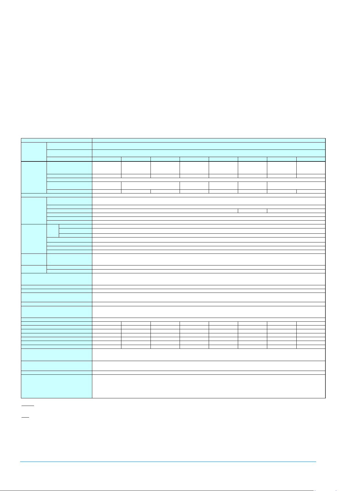
Technical Specification
NEC Express5800/A2040b (including COPT supported model)
Key Features
4U/up to 4way high performance with the latest Intel® Xeon® processor E7-8800v2, E7-4800v2 product family
Up to 4TB of memory capacity, supporting high speed and energy efficient DDR3L01600 memory
Redundant resources; service processors, clock and core I/O components
Capacity Optimization (COPT) supported model separately available in line-up for CPU resource optimization
Up to 8 2.5-inch HDD/SSD
High energy efficiency with 80 PLUS(RI Platinum certified power supply unit
NEC Corporation Revision 8.0 – April 2015
Page 5
CONFIGURATION GUIDE – NEC Express5800/A2040b, A2020b, A2010b, A1040b
5
Express5800/A2020b
Product Code CPU
NE3400-021F NE3400-022F NE3400-023F NE3400-024F NE3400-025F NE3400-026F NE3400-027F NE3400-028F
Intel® Xeon®
Processor
E7-4890 v2
Intel® Xeon®
Processor
E7-4870v2 *1
Intel® Xeon®
Processor
E7-4860v2
Intel® Xeon®
Processor
E7-4830v2
Intel® Xeon®
Processor
E7-4820v2
Intel® Xeon®
Processor
E7-4809v2 *1
Intel® Xeon®
Processor
E7-8891v2 *1
Intel® Xeon®
Processor
E7-8893v2
2.80GHz 2.30GHz 2.60GHz 2.20GHz 2.00GHz 1.90GHz 3.20GHz 3.40GHz
2
37.5MB 30MB 20MB 16MB 12MB 37.5MB
15C / 30T 15C/30T 12C/24T 10C / 20T 8C / 16T 6C / 12T 10C / 20T 6C / 12T
Intel® C602-J chipset
Not pre-installed
Registered DIMM : 1TB (64x 16GB), Load Reduced DIMM : 4TB (64x 64GB)
DDR3L-1600 Registered DIMM (8/16GB), DDR3L-1600 Load Reduced DIMM (32GB), DDR3L-1333 Load Reduced DIMM (64GB)
1333MHz
ECC, x4 SDDC (Independence mode), DDDC (LockStep mode)
Supported
Supported
-
HDD: 2.5-inch SAS 9.6TB (8x 1.2TB), SSD: 2.5-inch SAS 3.2TB (8x 400GB)
Supported
SAS 6Gb/s : RAID 0/1/5/6/10/50/60
Internal drive (option) *2
-
-
Expansion Slots
14x PCI Express 3.0 (x8 lane, x8 socket) (Low profile, 167.6mm in length)
2x PCI Express 3.0 (x4 lane, x8 socket) (Low profile, 167.6mm in length)
Embedded in management controller chip / 8MB
16,770,000 colors: 640x480, 800x600, 1,024x768, 1,152x864, 1,280x1,024, 1,600x1,200
5x USB2.0 (3x front, 1x rear, 1x internal), 1x Analog RGB (Mini D-Sub 15-pin, 1x front),
1x SUV ( 2x USB2.0, 1x serial (RS-232C/D-Sub 9-pin), 1x VGA (Mini D-Sub 15-pin))
2x Management LAN connector (1000BASE-T/100BASE-TX/10BASE-T, RJ-45, 2x rear)
Supported (hot-plug available)
Supported (standard, hot-plug available)
443.0mm x 719.3mm x 174.5mm (w/o protuberance/inner rail)
482.6mm x 892.5mm x 175.5mm (including protuberance/inner rail)
36kg / 55kg (including rail)
Not Pre-installed
800W or 1000W 80 PLUS® Platinum certified, hot plug (max. 4 units)
AC100V/200V±10%, 50/60Hz±3Hz
1442VA/1413W 1442VA/1413W 1442VA/1413W 1442VA/1413W 1442VA/1413W 1442VA/1413W 1442VA/1413W 1442VA/1413W
2169VA/2126W 2088VA/2046W 2088VA/2046W 2006VA/1966W 2006VA/1966W 2006VA/1966W 2169VA/2126W 2169VA/2126W
2220VA/2176W 2139VA/2096W 2139VA/2096W 2057VA/2016W 2057VA/2016W 2057VA/2016W 2220VA/2176W 2220VA/2176W
1435VA/1406W 1435VA/1406W 1435VA/1406W 1435VA/1406W 1435VA/1406W 1435VA/1406W 1435VA/1406W 1435VA/1406W
2157VA/2114W 2076VA/2034W 2076VA/2034W 1994VA/1954W 1994VA/1954W 1994VA/1954W 2157VA/2114W 2157VA/2114W
2208VA/2164W 2127VA/2084W 2127VA/2084W 2045VA/2004W 2045VA/2004W 2045VA/2004W 2208VA/2164W 2208VA/2164W
7834KJ/h 7546KJ/h 7546KJ/h 7258KJ/h 7258KJ/h 7258KJ/h 7834KJ/h 7834KJ/h
Operating: 10 to 40℃ / 50 to 104℉, 20 to 80%
Non-Operating: -10 to 55℃ / 14 to 131℉, 20 to 80% (no condensation either when operating or when stored)
EXPRESSBUILDER (NEC ESMPRO Manager (Windows/Linux), NEC ESMPRO Agent, User's Guide (electronic document) included),
Getting Started, SUV Cable, Rack Mount Kit
-
Microsoft® Windows Server® 2008 R2 Standard (SP1 or later), Microsoft® Windows Server® 2008 R2 Enterprise (SP1 or later),
Microsoft® Windows Server® 2012 Standard, Microsoft® Windows Server® 2012 Datacenter
Microsoft® Windows Server® 2012 R2 Standard *4, Microsoft® Windows Server® 2012 R2 Datacenter *4
Red Hat® Enterprise Linux® 6.4 or later (x86_64), Oracle® Linux 6.4/UEK R2 or later (x86_64)
VMware® ESXi™ 5.1 Update 2, VMware® ESXi™ 5.1 Update 3
VMware® ESXi™ 5.5, VMware® ESXi™ 5.5 Update 1, VMware® ESXi™ 5.5 Update 2
Remarks
Standby (shown in the Power Consumption) means the status before log-in at OS booted.
Note;
*1 CTO categorized item; lead time for delivery is different from other item
*2 Either internal DVD-ROM or DVD SuperMULTI should be installed for maintenance and/or OS re-installation purpose.
*3 Minimum configuration: 2x CPU, 2x DIMM, 0x HDD, 1x PCIe Card, 2x 800W Power Supply Unit
*4 Need to use "Support Kit" provided through web site in order to install at users site.
Model Name
CPU
Processor
Clock Speed
Number of CPUs
3rd Cache
Number of Cores (C) / Thread (T) per CPU
Chipset
Memory
Capacity, standard/maximum
Memory Module
Maximum Clock Speed
Error Check, Correction
Rank Sparing
Memory Mirroring
Redundant Power Supply
Auxiliary Storage
Device
Hard
Disk
Drive
Internal (standard)
Internal (maximum)
Hot Plug
Interface / RAID Level
Optical Disk Drive
FDD
Expansion Bay
Supported Slots
Graphics
Chip/Video RAM
Graphic Display / Resolution
Standard Interface
(100V max. configuration , 25℃ High Load)
(100V max. configuration , Maximum)
(200V max. configuration , 25℃ Standby)
(200V max. configuration , 25℃ High Load)
(200V max. configuration , Maximum)
1600MHz
1600MHz
Environmental Requirements
Temperature/Humidity
Accessories
Installed OS
Supported OS
Calorific Value (KJ/h)
Redundant Fan
External Dimensions (width x depth x height)
Weight (min.*3 / max.)
Power Supply Unit
Power Consumption
(100V max. configuration , 25℃ Standby)
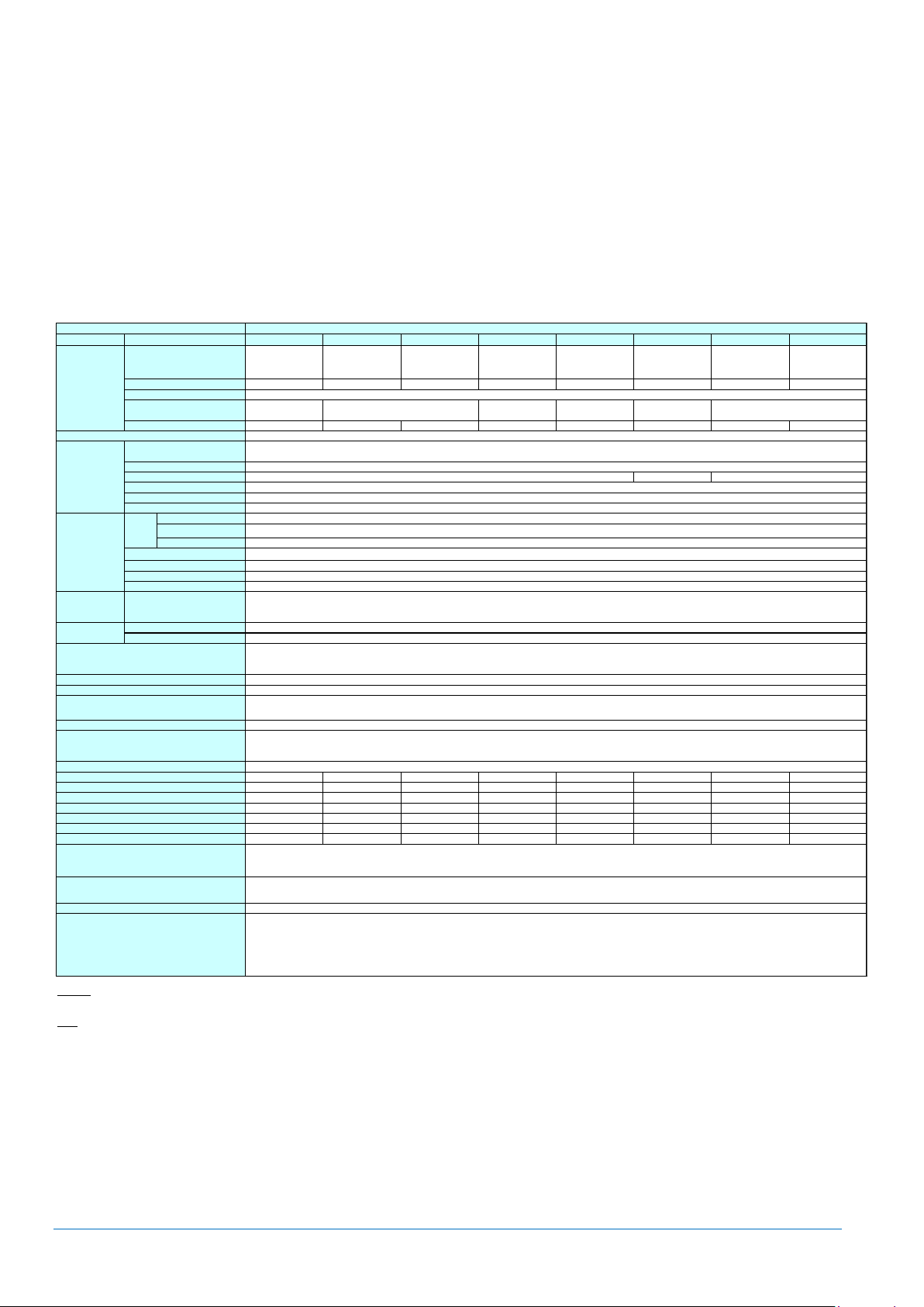
NEC Express5800/A2020b
Key Features
4U/2way server with high performance with the latest Intel® Xeon® processor E7-8800v2, E7-4800v2 product family
Up to 4TB of memory capacity, supporting high speed and energy efficient DDR3L01600 memory
Superior I/O scalability: up to 16 PCI Express 3.0 slots
Redundant resources; service processors, clock and core I/O components
Up to 8 2.5-inch HDD/SSD
High energy efficiency with 80 PLUS(RI Platinum certified power supply unit
NEC Corporation Revision 8.0 – April 2015
Page 6

CONFIGURATION GUIDE – NEC Express5800/A2040b, A2020b, A2010b, A1040b
6
Express5800/A2010b
Product Code CPU
NE3400-031F NE3400-032F NE3400-033F NE3400-034F NE3400-035F NE3400-036F NE3400-037F NE3400-038F
Intel® Xeon®
Processor
E7-4890 v2
Intel® Xeon®
Processor
E7-4870v2 *1
Intel® Xeon®
Processor
E7-4860v2
Intel® Xeon®
Processor
E7-4830v2
Intel® Xeon®
Processor
E7-4820v2
Intel® Xeon®
Processor
E7-4809v2 *1
Intel® Xeon®
Processor
E7-8891v2 *1
Intel® Xeon®
Processor
E7-8893v2
2.80GHz 2.30GHz 2.60GHz 2.20GHz 2.00GHz 1.90GHz 3.20GHz 3.40GHz
1
37.5MB 30MB 20MB 16MB 12MB 37.5MB
15C / 30T 15C/30T 12C/24T 10C / 20T 8C / 16T 6C / 12T 10C / 20T 6C / 12T
Intel® C602-J chipset
Not pre-installed
Registered DIMM : 512GB (32x 16GB), Load Reduced DIMM : 2TB (32x 64GB)
DDR3L-1600 Registered DIMM (8/16GB), DDR3L-1600 Load Reduced DIMM (32GB), DDR3L-1333 Load Reduced DIMM (64GB)
1333MHz
ECC, x4 SDDC (Independence mode), DDDC (LockStep mode)
Supported
Supported
-
HDD: 2.5-inch SAS 9.6TB (8x 1.2TB), SSD: 2.5-inch SAS 3.2TB (8x 400GB)
Supported
SAS 6Gb/s : RAID 0/1/5/6/10/50/60
Internaldrive (option) *2
-
-
Expansion Slots
7x PCI Express 3.0 (x8 lane, x8 socket) (Low profile, 167.6mm in length)
2x PCI Express 3.0 (x4 lane, x8 socket) (Low profile, 167.6mm in length)
Embedded in management controller chip / 8MB
16,770,000 colors: 640x480, 800x600, 1,024x768, 1,152x864, 1,280x1,024, 1,600x1,200
5x USB2.0 (3x front, 1x rear, 1x internal), 1x Analog RGB (Mini D-Sub 15-pin, 1x front),
1x SUV ( 2x USB2.0, 1x serial (RS-232C/D-Sub 9-pin), 1x VGA (Mini D-Sub 15-pin))
2x Management LAN connector (1000BASE-T/100BASE-TX/10BASE-T, RJ-45, 2x rear)
Supported (hot-plug available)
Supported (standard, hot-plug available)
443.0mm x 719.3mm x 174.5mm (w/o protuberance/inner rail)
482.6mm x 892.5mm x 175.5mm (including protuberance/inner rail)
36kg / 49kg (including rail)
Not Pre-installed
800W or 1000W 80 PLUS® Platinum certified, hot plug (max. 4 units)
AC100V/200V±10%, 50/60Hz±3Hz
1033VA/1012W 1033VA/1012W 1033VA/1012W 1033VA/1012W 1033VA/1012W 1033VA/1012W 1033VA/1012W 1033VA/1012W
1370VA/1343W 1330VA/1303W 1330VA/1303W 1289VA/1263W 1289VA/1263W 1289VA/1263W 1370VA/1343W 1370VA/1343W
1421VA/1393W 1381VA/1353W 1381VA/1353W 1340VA/1313W 1340VA/1313W 1340VA/1313W 1421VA/1393W 1421VA/1393W
1028VA/1007W 1028VA/1007W 1028VA/1007W 1028VA/1007W 1028VA/1007W 1028VA/1007W 1028VA/1007W 1028VA/1007W
1363VA/1336W 1322VA/1296W 1322VA/1296W 1282VA/1256W 1282VA/1256W 1282VA/1256W 1363VA/1336W 1363VA/1336W
1414VA/1386W 1373VA/1346W 1373VA/1346W 1333VA/1306W 1333VA/1306W 1333VA/1306W 1414VA/1386W 1414VA/1386W
5015KJ/h 4871KJ/h 4871KJ/h 4727KJ/h 4727KJ/h 4727KJ/h 5015KJ/h 5015KJ/h
Operating: 10 to 40℃ / 50 to 104℉, 20 to 80%
Non-Operating: -10 to 55℃ / 14 to 131℉, 20 to 80% (no condensation either when operating or when stored)
EXPRESSBUILDER (NEC ESMPRO Manager (Windows/Linux), NEC ESMPRO Agent, User's Guide (electronic document) included),
Getting Started, SUV Cable, Rack Mount Kit
-
Microsoft® Windows Server® 2008 R2 Standard (SP1 or later), Microsoft® Windows Server® 2008 R2 Enterprise (SP1 or later),
Microsoft® Windows Server® 2012 Standard, Microsoft® Windows Server® 2012 Datacenter
Microsoft® Windows Server® 2012 R2 Standard *4, Microsoft® Windows Server® 2012 R2 Datacenter *4
Red Hat® Enterprise Linux® 6.4 or later (x86_64), Oracle® Linux 6.4/UEK R2 or later (x86_64)
VMware® ESXi™ 5.1 Update 2, VMware® ESXi™ 5.1 Update 3
VMware® ESXi™ 5.5, VMware® ESXi™ 5.5 Update 1, VMware® ESXi™ 5.5 Update 2
Remarks
Standby (shown in the Power Consumption) means the status before log-in at OS booted.
Note;
*1 CTO categorized item; lead time for delivery is different from other item
*2 Either internal DVD-ROM or DVD SuperMULTI should be installed for maintenance and/or OS re-installation purpose.
*3 Minimum configuration: 1x CPU, 2x DIMM, 0x HDD, 1x PCIe Card, 2x 800W Power Supply Unit
*4 Need to use "Support Kit" provided through web site in order to install at users site.
Model Name
CPU
Processor
Clock Speed
Number of CPUs
3rd Cache
Number of Cores (C) / Thread (T) per CPU
Chipset
Memory
Capacity, standard/maximum
Memory Module
Maximum Clock Speed
Error Check, Correction
Rank Sparing
Memory Mirroring
Redundant Power Supply
Auxiliary Storage
Device
Hard
Disk
Drive
Internal (standard)
Internal (maximum)
Hot Plug
Interface / RAID Level
Optical Disk Drive
FDD
Expansion Bay
Supported Slots
Graphics
Chip/Video RAM
Graphic Display / Resolution
Standard Interface
(100V max. configuration , 25℃ High Load)
(100V max. configuration , Maximum)
(200V max. configuration , 25℃ Standby)
(200V max. configuration , 25℃ High Load)
(200V max. configuration , Maximum)
1600MHz
1600MHz
Environmental Requirements
Temperature/Humidity
Accessories
Installed OS
Supported OS
Calorific Value (KJ/h)
Redundant Fan
External Dimensions (width x depth x height)
Weight (min.*3 / max.)
Power Supply Unit
Power Consumption
(100V max. configuration , 25℃ Standby)
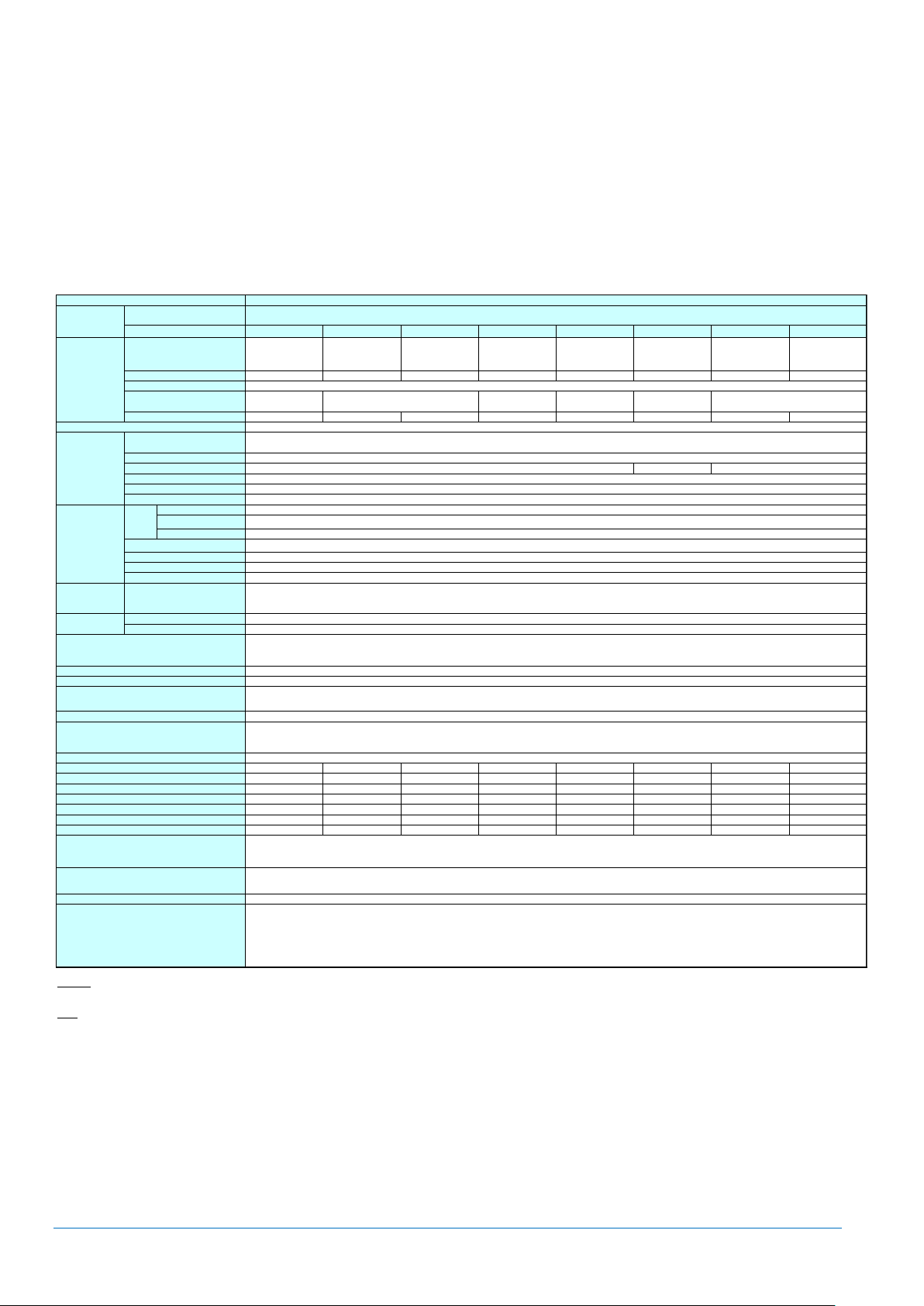
NEC Express5800/A2010b
Key Features
4U/1way server with high performance with the latest Intel® Xeon® processor E7-8800v2, E7-4800v2 product family
Up to 2TB of memory capacity, supporting high speed and energy efficient DDR3L01600 memory
Superior I/O scalability: up to 9 PCI Express 3.0 slots
Redundant resources; service processors, clock and core I/O components
Up to 8 2.5-inch HDD/SSD
High energy efficiency with 80 PLUS(RI Platinum certified power supply unit
NEC Corporation Revision 8.0 – April 2015
Page 7
CONFIGURATION GUIDE – NEC Express5800/A2040b, A2020b, A2010b, A1040b
7
Express5800/A1040b
Product Code
CPU
NE3301-H001F NE3301-H002F NE3301-H003F NE3301-H004F NE3301-H005F NE3301-H006F NE3301-H007F NE3301-H008F
Intel® Xeon®
Processor
E7-4890 v2
Intel® Xeon®
Processor
E7-4870v2 *1
Intel® Xeon®
Processor
E7-4860v2
Intel® Xeon®
Processor
E7-4830v2
Intel® Xeon®
Processor
E7-4820v2
Intel® Xeon®
Processor
E7-4809v2 *1
Intel® Xeon®
Processor
E7-8891v2 *1
Intel® Xeon®
Processor
E7-8893v2
2.80GHz 2.30GHz 2.60GHz 2.20GHz 2.00GHz 1.90GHz 3.20GHz 3.40GHz
1/4
37.5MB 30MB 20MB 16MB 12MB 37.5MB
15C / 30T 15C/30T 12C/24T 10C / 20T 8C / 16T 6C / 12T 10C / 20T 6C / 12T
Intel® C602-J chipset
Not pre-installed
Registered DIMM : 1TB (64x 16GB), Load Reduced DIMM : 4TB (64x 64GB)
DDR3L-1600 Registered DIMM (8/16GB), DDR3L-1600 Load Reduced DIMM (32GB), DDR3L-1333 Load Reduced DIMM (64GB)
1333MHz
ECC, x4 SDDC (Independence mode), DDDC (LockStep mode)
Supported
Supported
-
HDD: 2.5-inch SAS 9.6TB (8x 1.2TB), SSD: 2.5-inch SAS 3.2TB (8x 400GB)
Supported
SAS 6Gb/s : RAID 0/1/5/6/10/50/60
Internal drive (option) *2
-
-
Expansion Slots
14x PCI Express 3.0 (x8 lane, x8 socket) (Low profile, 167.6mm in length)
2x PCI Express 3.0 (x4 lane, x8 socket) (Low profile, 167.6mm in length)
Embedded in management controller chip / 8MB
16,770,000 colors: 640x480, 800x600, 1,024x768, 1,152x864, 1,280x1,024, 1,600x1,200
5x USB2.0 (3x front, 1x rear, 1x internal), 1x Analog RGB (Mini D-Sub 15-pin, 1x front),
1x SUV ( 2x USB2.0, 1x serial (RS-232C/D-Sub 9-pin), 1x VGA (Mini D-Sub 15-pin))
1x Management LAN connector (1000BASE-T/100BASE-TX/10BASE-T, RJ-45, 1x rear)
Supported (hot-plug available)
Supported (standard, hot-plug available)
443.0mm x 719.3mm x 174.5mm (w/o protuberance/inner rail)
482.6mm x 892.5mm x 175.5mm (including protuberance/inner rail)
35kg / 54kg (including rail)
Not Pre-installed
800W or 1000W 80 PLUS® Platinum certified, hot plug (max. 4 units)
AC100V/200V±10%, 50/60Hz±3Hz
1435VA/1406W 1435VA/1406W 1435VA/1406W 1435VA/1406W 1435VA/1406W 1435VA/1406W 1435VA/1406W 1435VA/1406W
2288VA/2242W 2186VA/2142W 2186VA/2142W 2084VA/2042W 2084VA/2042W 2084VA/2042W 2288VA/2242W 2288VA/2242W
2339VA/2292W 2237VA/2192W 2237VA/2192W 2135VA/2092W 2135VA/2092W 2135VA/2092W 2339VA/2292W 2339VA/2292W
1428VA/1399W 1428VA/1399W 1428VA/1399W 1428VA/1399W 1428VA/1399W 1428VA/1399W 1428VA/1399W 1428VA/1399W
2277VA/2231W 2174VA/2131W 2174VA/2131W 2072VA/2031W 2072VA/2031W 2072VA/2031W 2277VA/2231W 2277VA/2231W
2328VA/2281W 2226VA/2181W 2226VA/2181W 2123VA/2081W 2123VA/2081W 2123VA/2081W 2328VA/2281W 2328VA/2281W
8251KJ/h 7891KJ/h 7891KJ/h 7531KJ/h 7531KJ/h 7531KJ/h 8251KJ/h 8251KJ/h
Operating: 10 to 40℃ / 50 to 104℉, 20 to 80%
Non-Operating: -10 to 55℃ / 14 to 131℉, 20 to 80% (no condensation either when operating or when stored)
EXPRESSBUILDER (NEC ESMPRO Manager (Windows/Linux), NEC ESMPRO Agent, User's Guide (electronic document) included),
Getting Started, SUV Cable, Rack Mount Kit
-
Microsoft® Windows Server® 2008 R2 Standard (SP1 or later), Microsoft® Windows Server® 2008 R2 Enterprise (SP1 or later),
Microsoft® Windows Server® 2012 Standard, Microsoft® Windows Server® 2012 Datacenter
Microsoft® Windows Server® 2012 R2 Standard *4, Microsoft® Windows Server® 2012 R2 Datacenter *4
Red Hat® Enterprise Linux® 6.4 or later (x86_64), Oracle® Linux 6.4/UEK R2 or later (x86_64)
VMware® ESXi™ 5.1 Update 2, VMware® ESXi™ 5.1 Update 3
VMware® ESXi™ 5.5, VMware® ESXi™ 5.5 Update 1, VMware® ESXi™ 5.5 Update 2
Remarks
Standby (shown in the Power Consumption) means the status before log-in at OS booted.
Note;
*1 CTO categorized item; lead time for delivery is different from other item
*2 Either internal DVD-ROM or DVD SuperMULTI should be installed for maintenance and/or OS re-installation purpose.
*3 Minimum configuration: 1x CPU, 2x DIMM, 0x HDD, 1x PCIe Card, 2x 1000W Power Supply Unit
*4 Need to use "Support Kit" provided through web site in order to install at users site.
Model Name
Base Unit
NE3300-040F
CPU
Processor
Clock Speed
Number of CPUs, min./max.
3rd Cache
Number of Cores (C) / Thread (T) per CPU
Chipset
Memory
Capacity, standard/maximum
Memory Module
Maximum Clock Speed
Error Check, Correction
Rank Sparing
Memory Mirroring
Redundant Power Supply
Auxiliary Storage
Device
Hard
Disk
Drive
Internal (standard)
Internal (maximum)
Hot Plug
Interface / RAID Level
Optical Disk Drive
FDD
Expansion Bay
Supported Slots
Graphics
Chip/Video RAM
Graphic Display / Resolution
Standard Interface
(100V max. configuration , 25℃ High Load)
(100V max. configuration , Maximum)
(200V max. configuration , 25℃ Standby)
(200V max. configuration , 25℃ High Load)
(200V max. configuration , Maximum)
1600MHz
1600MHz
Environmental Requirements
Temperature/Humidity
Accessories
Installed OS
Supported OS
Calorific Value (KJ/h)
Redundant Fan
External Dimensions (width x depth x height)
Weight (min.*3 / max.)
Power Supply Unit
Power Consumption
(100V max. configuration , 25℃ Standby)
NEC Express5800/A1040b
Key Features
4U/up to 4way server with high performance with the latest Intel® Xeon® processor E7-8800v2, E7-4800v2 product family
Up to 4TB of memory capacity, supporting high speed and energy efficient DDR3L01600 memory
Up to 8 2.5-inch HDD/SSD
High energy efficiency with 80 PLUS(RI Platinum certified power supply unit
NEC Corporation Revision 8.0 – April 2015
Page 8
CONFIGURATION GUIDE – NEC Express5800/A2040b, A2020b, A2010b, A1040b
8
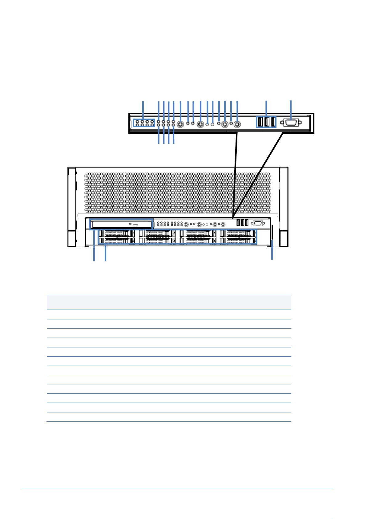
Legend
A.
Location LED
M.
BMC OFF Button
B.
PSU/FAN LED
N.
NMI Button
C.
PCI LED
O.
RESET Button
D.
MEM LED
P.
UID LED
E.
CPU LED
Q.
UID Button
F.
VLT/TMP LED (Voltage/Temperature)
R.
SYSTEM POWER LED
G.
CNFG LED (Configuration)
S.
SYSTEM POWER Button
H.
MISC LED
T.
USB Connectors
I.
NEXT LED
U.
VGA Connector
J.
NEXT Button
V.
Optical Drive Bay
K.
DISK Access LED
W.
2.5-inch Drive Bays
L.
SYSTEM STATUS LED
X.
Slide Tag
A B P
Q
R
E G I D F
J K L M N B C H
O
S T U
V W X
External Views
Front and Rear Views
Front View
NEC Corporation Revision 8.0 – April 2015
Page 9
CONFIGURATION GUIDE – NEC Express5800/A2040b, A2020b, A2010b, A1040b
9
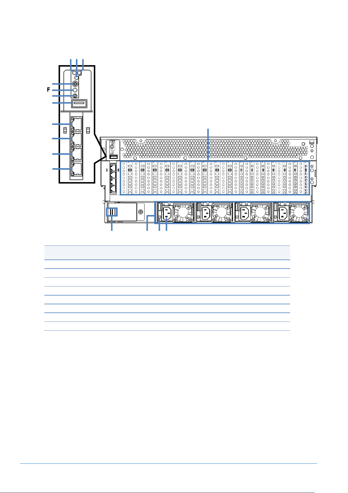
Legend
A.
MGB#1 Status LED
I.
MGB#1 Maintenance LAN Connector
B.
UID LED
J.
MGB#1 Management LAN Connector
C.
MGB#2 Status LED *1
K.
MGB#2 Maintenance LAN Connector *1
D.
PCI Slots (Low Profile)
L.
MGB#2 Management LAN Connector *1
E.
UID Button
M.
SUVCable Connector *2
F.
MGB#1 RESET Button
N.
Power Supply Unit
G.
MGB#2 RESET Button *1
O.
AC POWER LED
H.
USB Connector
P.
AC Inlet
A
C
D F G H I
J
K
L
M E N
O
B
P
Rear View
*1 Not applicable to A1040b
*2 2x USB Connectors and 1x Serial Port and 1 x VGA Connector can be connected through SUB Cable
(attached to Base Models, 2m length)
NEC Corporation Revision 8.0 – April 2015
Page 10
CONFIGURATION GUIDE – NEC Express5800/A2040b, A2020b, A2010b, A1040b
10
*
*
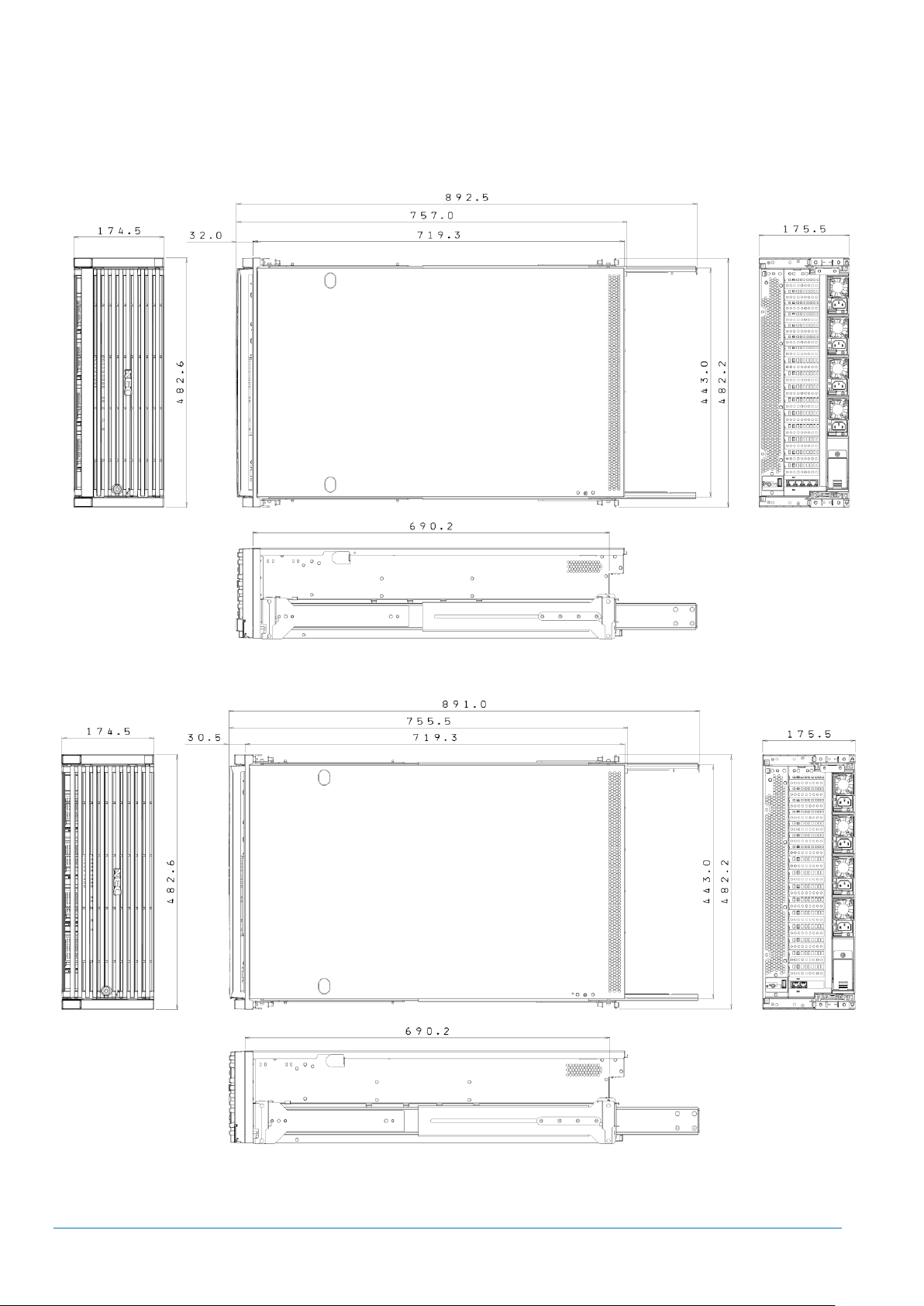
Dimensions (mm)
A2040b/A2020b/A2010b
A1040b
* In case of using slide rail attachment (cable arm in use)
NEC Corporation Revision 8.0 – April 2015
The above illustrations including inner rail.
Page 11
CONFIGURATION GUIDE – NEC Express5800/A2040b, A2020b, A2010b, A1040b
11
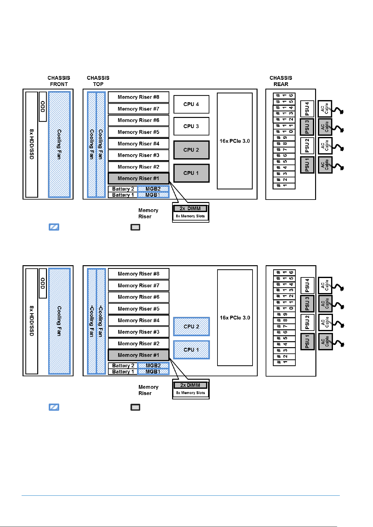
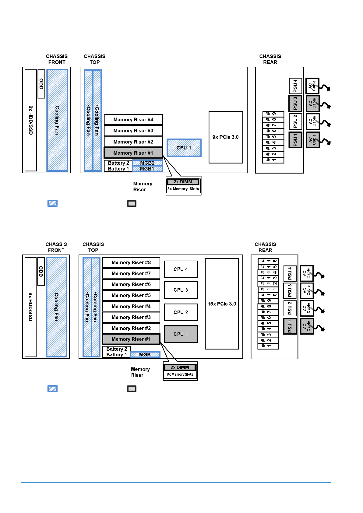
Configuration Diagram
A2040b
Legend: Standard components Minimum required components
A2020b
Legend: Standard components Minimum required components
NEC Corporation Revision 8.0 – April 2015
Page 12
CONFIGURATION GUIDE – NEC Express5800/A2040b, A2020b, A2010b, A1040b
12
A2010b
Legend: Standard components Minimum required components
A1040b
Legend: Standard components Minimum required components
NEC Corporation Revision 8.0 – April 2015
Page 13
CONFIGURATION GUIDE – NEC Express5800/A2040b, A2020b, A2010b, A1040b
13
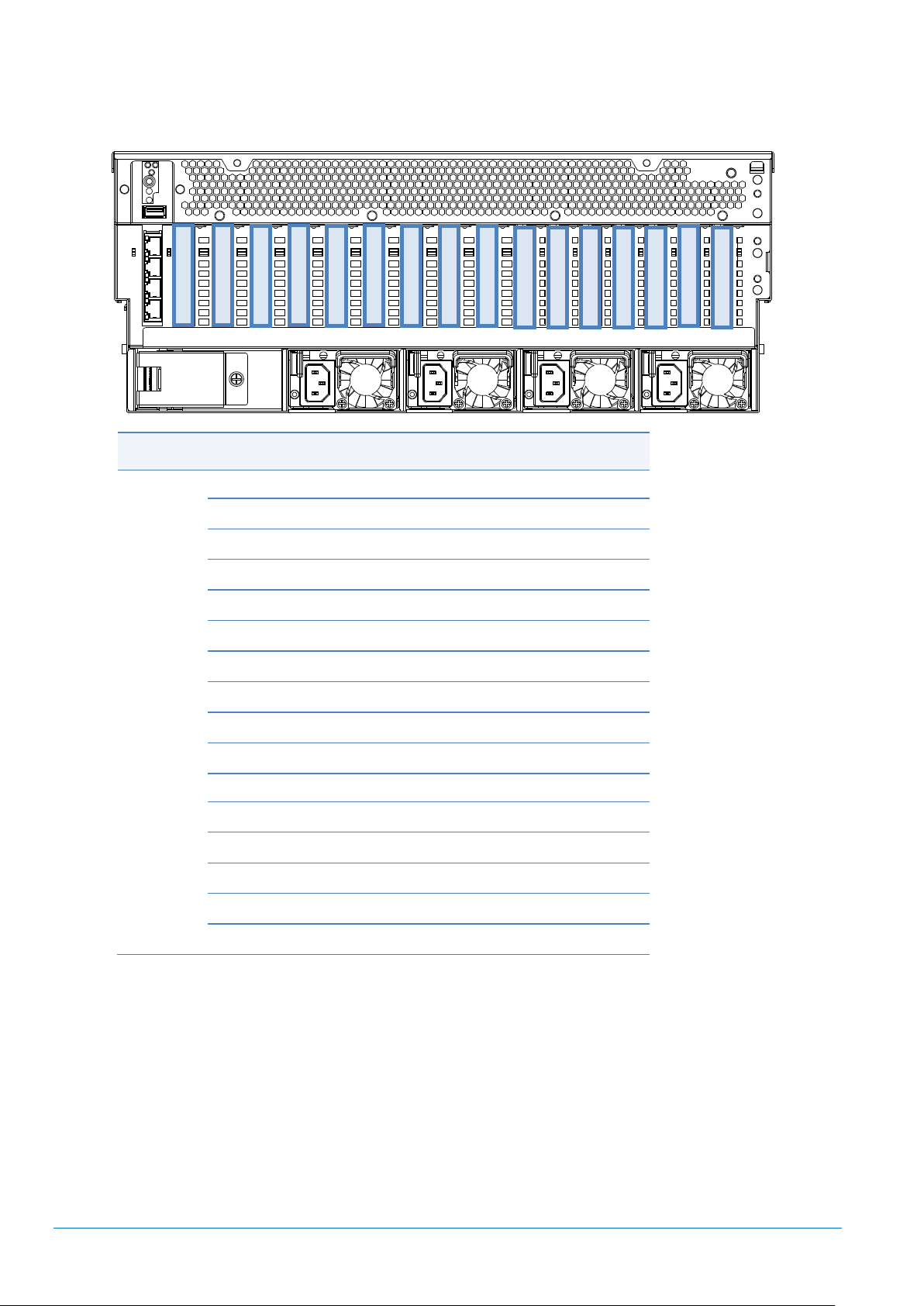
Legend
Slot #1
PCI Express 3.0 (x8 lane, x8 socket)
Slot #2
PCI Express 3.0 (x8 lane, x8 socket)
Slot #3
PCI Express 3.0 (x8 lane, x8 socket)
Slot #4
PCI Express 3.0 (x8 lane, x8 socket)
Slot #5
PCI Express 3.0 (x8 lane, x8 socket)
Slot #6
PCI Express 3.0 (x8 lane, x8 socket)
Slot #7
PCI Express 3.0 (x8 lane, x8 socket)
Slot #8
PCI Express 3.0 (x4 lane, x8 socket)
Slot #9
PCI Express 3.0 (x4 lane, x8 socket)
Slot #10
PCI Express 3.0 (x8 lane, x8 socket)
Slot #11
PCI Express 3.0 (x8 lane, x8 socket)
Slot #12
PCI Express 3.0 (x8 lane, x8 socket)
Slot #13
PCI Express 3.0 (x8 lane, x8 socket)
Slot #14
PCI Express 3.0 (x8 lane, x8 socket)
Slot #15
PCI Express 3.0 (x8 lane, x8 socket)
Slot #16
PCI Express 3.0 (x8 lane, x8 socket)
Slot #1
Slot #2
Slot #3
Slot #4
Slot #5
Slot #6
Slot #7
Slot #8
Slot #9
Slot #10
Slot #11
Slot #12
Slot #13
Slot #14
Slot #15
Slot #16
Expansion Slot
NOTE:
Foa all PCI slot: Low Profile, 167.6mm in length
PCI slot performance: x4 lane for Slot #8 and #9, x8 lane for the others
Hot Plug supported: Slot #2 to #9 (8 slots), except for A1040b
For A2040b: Slot#1 to #9 are available in case of 2CPU configuration, Slot#1 to #13 are available in case
of 3CPU configuration and Slot#1 to #16 are available in case of 4CPU configuration.
For A2020b: Slot#1 to #16 are available
For A2010b: Slot#1 to #9 are available
For A1040b: Slot#1 and Slot#3 to #5 are available in case of 1CPU configuration, Slot#1 to #9 are
available in case of 2CPU configuration, Slot#1 to #13 are available in case of 3CPU configuration and
Slot#1 to #16 are available in case of 4CPU configuration
NEC Corporation Revision 8.0 – April 2015
Page 14

CONFIGURATION GUIDE – NEC Express5800/A2040b, A2020b, A2010b, A1040b
14
Product Name/Description
Part Number
NEC Express5800/A2040b
no processor, no RAM, no HDD, no ODD, no Power Supply Unit, no OS
NE3400-040F
NEC Express5800/A2040b (COPT)
no processor, no RAM, no HDD, no ODD, no Power Supply Unit, no OS
NE3400-041F
No. of
CPU
Max. No. of
Memory
Riser
Available PCI Slots
#1
#2
#3
#4
#5
#6
#7
#8
#9
#10
#11
#12
#13
#14
#15
#16
2 4 Y ‐ ‐ ‐ ‐ ‐ ‐
3 6 Y ‐ ‐
‐
4 8 Y
Server Configuration
1 Base Models
1.1 A2040b
NOTE:
The base model must be ordered with processor kits, memory riser cards, memory kit, power supply
units and power cables.
Front Bezel and Cable Arm are not attached; need to be ordered separately if required.
Number of the available PCI Slots and Memory Riser Card depends on the number of CPUs
<Available PCI Slots and Maximum No. of Memory Riser Card>
NEC Corporation Revision 8.0 – April 2015
Page 15

CONFIGURATION GUIDE – NEC Express5800/A2040b, A2020b, A2010b, A1040b
15
Product Name/Description
Part Number
NEC Express5800/A2020b (15C/E7-4890v2)
2x Intel® Xeon® Processor E7-4890v2 (2.80 GHz, 15C/30T, 37.5 MB)
no RAM, no HDD, no ODD, no Power Supply Unit, no OS
NE3400-021F
NEC Express5800/A2020b (15C/E7-4870v2) (*CTO*)
2x Intel® Xeon® Processor E7-4870v2 (2.30 GHz, 15C/30T, 30 MB)
no RAM, no HDD, no ODD, no Power Supply Unit, no OS
NE3400-022F
NEC Express5800/A2020b (12C/E7-4860v2)
2x Intel® Xeon® Processor E7-4860v2 (2.60 GHz, 12C/24T, 30 MB)
no RAM, no HDD, no ODD, no Power Supply Unit, no OS
NE3400-023F
NEC Express5800/A2020b (10C/E7-4830v2)
2x Intel® Xeon® Processor E7-4830v2 (2.20 GHz, 10C/20T, 20 MB)
no RAM, no HDD, no ODD, no Power Supply Unit, no OS
NE3400-024F
NEC Express5800/A2020b (8C/E7-4820v2)
2x Intel® Xeon® Processor E7-4820v2 (2.00 GHz, 8C/16T, 16 MB)
no RAM, no HDD, no ODD, no Power Supply Unit, no OS
NE3400-025F
NEC Express5800/A2020b (6C/E7-4809v2) (*CTO*)
2x Intel® Xeon® Processor E7-4809v2 (1.90 GHz, 6C/12T, 12 MB)
no RAM, no HDD, no ODD, no Power Supply Unit, no OS
NE3400-026F
NEC Express5800/A2020b (10C/E7-8891v2) (*CTO*)
2x Intel® Xeon® Processor E7-8891v2 (3.20 GHz, 10C/20T, 37.5 MB)
no RAM, no HDD, no ODD, no Power Supply Unit, no OS
NE3400-027F
NEC Express5800/A2020b (6C/E7-8893v2)
2x Intel® Xeon® Processor E7-8893v2 (3.40 GHz, 6C/12T, 37.5 MB)
no RAM, no HDD, no ODD, no Power Supply Unit, no OS
NE3400-028F
No. of
CPU
Max. No. of
Memory
Riser
Available PCI Slots
#1
#2
#3
#4
#5
#6
#7
#8
#9
#10
#11
#12
#13
#14
#15
#16
2 8 Y
1.2 A2020b
NOTE:
The base model must be ordered with memory riser cards, memory kit, power supply units and power
cables.
Front Bezel and Cable Arm are not attached; need to be ordered separately if required.
2CPU (fixed) model: cannot add CPU
(*CTO*) CTO categorized item; lead time for delivery is different from other item.
<Available PCI Slots and Maximum No. of Memory Riser Card>
NEC Corporation Revision 8.0 – April 2015
Page 16

CONFIGURATION GUIDE – NEC Express5800/A2040b, A2020b, A2010b, A1040b
16
Product Name/Description
Part Number
NEC Express5800/A2010b (15C/E7-4890v2)
1x Intel® Xeon® Processor E7-4890v2 (2.80 GHz, 15C/30T, 37.5 MB)
no RAM, no HDD, no ODD, no Power Supply Unit, no OS
NE3400-031F
NEC Express5800/A2010b (15C/E7-4870v2) (*CTO*)
1x Intel® Xeon® Processor E7-4870v2 (2.30 GHz, 15C/30T, 30 MB)
no RAM, no HDD, no ODD, no Power Supply Unit, no OS
NE3400-032F
NEC Express5800/A2010b (12C/E7-4860v2)
1x Intel® Xeon® Processor E7-4860v2 (2.60 GHz, 12C/24T, 30 MB)
no RAM, no HDD, no ODD, no Power Supply Unit, no OS
NE3400-033F
NEC Express5800/A2010b (10C/E7-4830v2)
1x Intel® Xeon® Processor E7-4830v2 (2.20 GHz, 10C/20T, 20 MB)
no RAM, no HDD, no ODD, no Power Supply Unit, no OS
NE3400-034F
NEC Express5800/A2010b (8C/E7-4820v2)
1x Intel® Xeon® Processor E7-4820v2 (2.00 GHz, 8C/16T, 16 MB)
no RAM, no HDD, no ODD, no Power Supply Unit, no OS
NE3400-035F
NEC Express5800/A2010b (6C/E7-4809v2) (*CTO*)
1x Intel® Xeon® Processor E7-4809v2 (1.90 GHz, 6C/12T, 12 MB)
no RAM, no HDD, no ODD, no Power Supply Unit, no OS
NE3400-036F
NEC Express5800/A2010b (10C/E7-8891v2) (*CTO*)
1x Intel® Xeon® Processor E7-8891v2 (3.20 GHz, 10C/20T, 37.5 MB)
no RAM, no HDD, no ODD, no Power Supply Unit, no OS
NE3400-037F
NEC Express5800/A2010b (6C/E7-8893v2)
1x Intel® Xeon® Processor E7-8893v2 (3.40 GHz, 6C/12T, 37.5 MB)
no RAM, no HDD, no ODD, no Power Supply Unit, no OS
NE3400-038F
No. of
CPU
Max. No. of
Memory
Riser
Available PCI Slots
#1
#2
#3
#4
#5
#6
#7
#8
#9
#10
#11
#12
#13
#14
#15
#16
1 4 Y
Y
‐ ‐ ‐ ‐ ‐ ‐ ‐
1.3 A2010b
NOTE:
The base model must be ordered with memory riser cards, memory kit, power supply units and power
cables.
Front Bezel and Cable Arm are not attached; need to be ordered separately if required.
1CPU (fixed) model: cannot add CPU
(*CTO*) CTO categorized item; lead time for delivery is different from other item.
<Available PCI Slots and Maximum No. of Memory Riser Card>
NEC Corporation Revision 8.0 – April 2015
Page 17

CONFIGURATION GUIDE – NEC Express5800/A2040b, A2020b, A2010b, A1040b
17
Product Name/Description
Part Number
NEC Express5800/A1040b
no processor, no RAM, no HDD, no ODD, no Power Supply Unit, no OS
NE3300-040F
No. of
CPU
Max. No. of
Memory
Riser
Available PCI Slots
#1
#2
#3
#4
#5
#6
#7
#8
#9
#10
#11
#12
#13
#14
#15
#16
1 2 Y ‐ ‐ ‐ ‐ ‐ ‐ ‐ ‐ ‐ ‐
2 4 Y ‐ ‐ ‐ ‐ ‐ ‐
3 6 Y ‐ ‐
‐
4 8 Y
1.4 A1040b
NOTE:
The base model must be ordered with processor kits, memory riser cards, memory kit, power supply
units and power cables.
Front Bezel and Cable Arm are not attached; need to be ordered separately if required.
Number of the available PCI Slots and Memory Riser Card depends on the number of CPUs
<Available PCI Slots and Maximum No. of Memory Riser Card>
NEC Corporation Revision 8.0 – April 2015
Page 18
CONFIGURATION GUIDE – NEC Express5800/A2040b, A2020b, A2010b, A1040b
18
Product Name/Description
Part Number
One Core Activation Key (for Embedded)
Need to order at the same time of the server. As many CPU cores as the ordered
number of the One Core Activation Key (for Embedded) are to be enabled when
the ordered server is shipped.
Up to the ordered number of the One Core Activation Key (for Embedded), CPU
cores are available for use.
NE3401-H010F
One Core Activation Key (for Add-on)
The enabled CPU core can be added on-site.
As many Code Words as the ordered number of the One Core Activation Key (for
Add-on) are shipped, and additional CPU core can be enabled by applying the
Code Word to the server.
NE3401-H011F
Ex.1: OK
Ex.2: OK
Ex.3: NG
Ex.4: NG
CPU1: 1 core enabled
CPU1: 4 core enabled
CPU1: 2 core enabled
CPU1: 1 core enabled
CPU2: 1 core enabled
CPU2: 0 core enabled
CPU2: 1 core enabled
CPU2: 1 core enabled
CPU3: 1 core enabled
CPU3: 0 core enabled
CPU3: 1 core enabled
CPU3: 1 core enabled
CPU4: 1 core enabled
CPU4: 0 core enabled
CPU4: 0 core enabled
CPU4: 0 core enabled
1.5 COPT
Capacity Optimization (COPT) is a function to optimize computing resources by enabling CPU cores as many
required per workload without any impact to the number of DIMM and PCI slots which depends on CPU
configuration.
When necessary, CPU core can be enabled additionally on-site.
COPT is available only with A2040b COPT supported model (NEC Express5800/A2040b (COPT)).
In order to enable CPU core, Core Activation Key should be ordered for the required number of cores.
NOTE:
Contact to our sales representative for software supporting COPT function.
When enabling CPU core (or socket) by Core Activation Key, please purchase required software license
as appropriate
In case of using socket license based software, please enable CPU core at the CPU socket on which the
software is operating. Software license is required for the socket with at least one enabled CPU core.
Depending on the OS, the server may need to be rebooted to enable CPU cores
Remarks to use COPT under VMware environment:
- Need to purchase the same number of One Core Activation Key as the number of CPU socket.
- Need to enable the same count of CPU cores among all CPUs (excluding CPUs with all cores
disabled)
<Examples of OK or NG configuration in case of 4CPU configuration>
For the details, please refer to the latest version of “Express5800/A2040b Capacity Optimization (COPT)
User's Guide”
Default setting of Core Optimization Mode is “Decentralize”, where the enabled CPU cores are
distributed to each socket equally.
NEC Corporation Revision 8.0 – April 2015
Page 19

CONFIGURATION GUIDE – NEC Express5800/A2040b, A2020b, A2010b, A1040b
19
Product Name/Description
Part Number
Xeon E7-4890 v2 Processor Kit
1x Intel® Xeon® Processor E7-4890 v2(2.80 GHz, 15C/30T, 37.5MB)
NE3301-H001F
Xeon E7-4870v2 Processor Kit (*CTO*)
1x Intel® Xeon® Processor E7-4870v2 (2.30 GHz, 15C/30T, 30 MB)
NE3301-H002F
Xeon E7-4860v2 Processor Kit
1x Intel® Xeon® Processor E7-4860v2 (2.60 GHz, 12C/24T, 30 MB)
NE3301-H003F
Xeon E7-4830v2 Processor Kit
1x Intel® Xeon® Processor E7-4830v2 (2.20 GHz, 10C/20T, 20 MB)
NE3301-H004F
Xeon E7-4820v2 Processor Kit
1x Intel® Xeon® Processor E7-4820v2 (2.00 GHz, 8C/16T, 16 MB)
NE3301-H005F
Xeon E7-4809v2 Processor Kit (*CTO*)
1x Intel® Xeon® Processor E7-4809v2 (1.90 GHz, 6C/12T, 12 MB)
NE3301-H006F
Xeon E7-8891v2 Processor Kit (*CTO*)
1x Intel® Xeon® Processor E7-8891v2 (3.20 GHz, 10C/20T, 37.5 MB)
NE3301-H007F
Xeon E7-8893v2 Processor Kit
1x Intel® Xeon® Processor E7-8893v2 (3.40 GHz, 6C/12T, 37.5 MB)
NE3301-H008F
2 CPU
A2040b (min. 2CPU / max. 4CPU)/ A1040b (min. 1CPU / max. 4CPU)
NOTE:
(*CTO*) CTO categorized item; lead time for delivery is different from other item.
Different SKU of CPU/Processors cannot be mixed in a server.
NEC Corporation Revision 8.0 – April 2015
Page 20

CONFIGURATION GUIDE – NEC Express5800/A2040b, A2020b, A2010b, A1040b
20
Category
Function Name/Summary
CPU
Xeon
E7-4809v2
Xeon
E7-4890v2,E7-4870v2
E7-4860v2,E7-4830v2
E7-4820v2
E7-8891v2,E7-8893v2
64 bit
Intel® 64
64 bit function
Power Saving
Enhanced Intel SpeedStep® Technology
(Intel® Demand Bases Switching Technology)
Technology to decrease power consumption by
adjusting voltage/clock per CPU workload
Performance
Intel® Turbo Boost Technology
Technology to boost clock frequency
‐
Performance
Intel® Hyper-Threading Technology
Technology to use one core as two threads
Virtualization
Intel® Virtualization Technology
Technology to provide hardware (CPU) support for
processor virtualization
Security
Execute Disable
Technology to avoid the execution of malware utilizing
buffer over flow error
Maximum Number of Logical Processors Supported by Operating
Systems
Maximum Number of
Logical Processors
Supported by this
Server
Microsoft Windows Server 2008 R2 SP1 Standard
Microsoft Windows Server 2008 R2 SP1 Enterprise
Microsoft Windows Server 2008 R2 SP1 Datacenter
256 1
120
Microsoft Windows Server 2012 Standard
Microsoft Windows Server 2012 Datacenter
Microsoft Windows Server 2012 R2 Standard
Microsoft Windows Server 2012 R2 Datacenter
640 1
120
Red Hat Enterprise Linux 6 (x86_64)
160
120
Oracle Linux 6 /UEK R2 (x86_64)
160
120
VMware ESXi 5.1
160
120
VMware ESXi 5.5
320
120
CPU Functions
Intel® Xeon® Processors for this server supports the following CPU functions
The maximum number of logical processors supported by OS
See the table below for the maximum number of logical processors that you can actually use on your system
1
The maximum number of logical processors when using Hyper-V are below:
Windows Server 2008 R2 SP1: 64 logical processors
Windows Server 2012, Windows Server 2012 R2 : 320 logical processors
NEC Corporation Revision 8.0 – April 2015
Page 21

CONFIGURATION GUIDE – NEC Express5800/A2040b, A2020b, A2010b, A1040b
21
Product Name/Description
Part Number
Memory Riser Card (16GB/32GB/64GB Memory Kit)
Module with 8x DIMM slots. Hot-plug supoprted
NE3402-H001
Memory Riser Card (16GB/32GB/64GB/128GB Memory Kit)
Module with 8x DIMM slots. Hot-plug supoprted
NE3402-H002
Product Name/Description
Part Number
Memory Riser Card (16GB/32GB/64GB Memory Kit)
Module with 8x DIMM slots. Hot-plug not supported
NE3302-H001
Memory Riser Card (16GB/32GB/64GB/128GB Memory Kit)
Module with 8x DIMM slots. Hot-plug not supported
NE3302-H002
Product Name/Description
Part Number
Customized Service: Distribution Mode for COPT
NE3300-SV101
3 Memory
3.1 Memory Riser Card
Memory Riser Card (“MR”) is a module for installing up to 8 DIMM
Please refer to “Memory” of “Reference” section for Memory Riser Card installation priority/order.
For A2040b (including COPT model), A2020b,A2010b
NOTE:
A2040b: 1 to 2 MRs can be installed per CPU, thus up to 8 MRs can be installed with 4CPU configuration
A2020b: Up to 8 MRs can be installed
A2010b: Up to 4 MRs can be installed
Not pre-installed in Base Model. At least one MR needs to be ordered.
Cover for Hot-plug is attached
NE3402-H001 and NE3402-H002 can be mixed in one server.
For A1040b
NOTE:
1 to 2 MRs can be installed per CPU, thus up to 8 MRs can be installed with 4CPU configuration
Not pre-installed in Base Model. At least one MR needs to be ordered.
NE3302-H001 and NE3302-H002 can be mixed in one server.
Customized Configuration Service (at the Server Delivery)
NOTE:
This service can be ordered only for A2040b COPT Model and up to one item (service) can be ordered
per one server.
With this service, the location of MR can be changed from the standard BTO Configuration.
When allocating enabled CPU cores to all CPU (distributed), this service is recommended to use so that
MR and Memory can be distributed, too. Please refer to “Memory” of “Reference” section for Memory
Riser Card installation priority/order.
NEC Corporation Revision 8.0 – April 2015
Page 22

CONFIGURATION GUIDE – NEC Express5800/A2040b, A2020b, A2010b, A1040b
22
Independent Mode
(only)
Memory Rank Sparing
under Independent
Mode
Memory Mirroring
under Independent Mode
Summary
In case of correctable
errors, switching to
spare memory rank
Redundant memory
Available Memory
-
1/2(8GB RDIMM),
3/4(16GB RDIMM),
7/8(32GB LRDIMM) or
3/4(64GB LRDIMM)
of physical memory
1/2 of physical memory
Available Memory
Channel 1
4 4 4
Maximum Memory
Capacity
2
512GB(8GB RDIMM)
1024GB(16GB RDIMM)
2048GB(32GB LRDIMM)
4096GB(64GB LRDIMM)
256GB(8GB RDIMM)
768GB(16GB RDIMM)
1792GB(32GB LRDIMM)
3072GB(64GB LRDIMM)
256GB(8GB RDIMM)
512GB(16GB RDIMM)
1024GB(32GB LRDIMM)
2048GB(64GB LRDIMM)
Data Correction
ECC, x4 SDDC
←
←
Notes
RDIMM and LRDIMM
cannot be mixed
RDIMM and LRDIMM
cannot be mixed
RDIMM and LRDIMM
cannot be mixed
3.2 Memory Configuration
Refer to the section in accordance with your memory configuration.
Memory configuration consists of 2 modes; “Independent Mode” and “Lockstep Mode”.
Under each Mode, 2 features are available; “Memory Rank Sparing” and “Memory Mirroring”.
Default setting at the server delivery is Lockstep Mode.
Independent Mode (only): Refer to 3.2.1
Lockstep Mode (only): Refer to 3.2.2
Memory Rank Sparing: Refer to 3.2.3
Memory Mirroring: Refer to 3.2.4
Please refer to “Memory” of “Reference” section for Memory on the Memory Riser Card (DIMM) installation
priority/order per Independent Mode, Lockstep Mode, Memory Rank Sparing and Memory Mirroring..
Memory Configuration Feature Comparison
See the table below for feature comparisons of memory configurations supported.
1
4 memory channels per Memory Riser Card.
2
All DIMMs have the same capacity
NEC Corporation Revision 8.0 – April 2015
Page 23

CONFIGURATION GUIDE – NEC Express5800/A2040b, A2020b, A2010b, A1040b
23
Lockstep Mode (only)
Memory Rank Sparing
under Lockstep Mode
Memory Mirroring
under Lockstep Mode
Summary
2 DRAM failure
detected/corrected by
memory parallel
operation
In case of correctable
errors, switching to
spare memory rank
Redundant memory
Available Memory
-
1/2(8GB RDIMM),
3/4(16GB RDIMM),
7/8(32GB LRDIMM) or
3/4(64GB LRDIMM)
of physical memory
1/2 of physical memory
Available Memory
Channel 3
4 4 4
Maximum Memory
Capacity 4
512GB(8GB RDIMM)
1024GB(16GB RDIMM)
2048GB(32GB LRDIMM)
4096GB(64GB LRDIMM)
256GB(8GB RDIMM)
768GB(16GB RDIMM)
1792GB(32GB LRDIMM)
3072GB(64GB LRDIMM)
256GB(8GB RDIMM)
512GB(16GB RDIMM)
1024GB(32GB LRDIMM)
2048GB(64GB LRDIMM)
Data Correction
ECC, DDDC
←
←
Notes
RDIMM and LRDIMM
cannot be mixed
RDIMM and LRDIMM
cannot be mixed
RDIMM and LRDIMM
cannot be mixed
Product Name/Description
Part Number
Customized Service: Distribution Mode for COPT
NE3300-SV101
3
4 memory channels per Memory Riser Card
4
All DIMMs have the same capacity
Customized Configuration Service (at the Server Delivery)
NOTE:
This service can be ordered only for A2040b COPT Model and up to one item (service) can be ordered
per one server.
With this service, according to the change of the location of MR, memory location can be changed from
the standard BTO Configuration.
When allocating enabled CPU cores to all CPU (distributed), this service is recommended to use so that
MR and Memory can be distributed, too. Please refer to “Memory” of “Reference” section for the details.
NEC Corporation Revision 8.0 – April 2015
Page 24

CONFIGURATION GUIDE – NEC Express5800/A2040b, A2020b, A2010b, A1040b
24
Category
Product Name/Description
Part Number
Registered
DIMM
(RDIMM)
1600
MHz
16GB MEM (2 x 8GB RDIMM)
2x 8GB Registered DIMM, DDR3L-1600(PC3L-12800), ECC
NE3302-H010F
32GB MEM (2x16GB RDIMM)
2x 16GB Registered DIMM, DDR3L-1600(PC3L-12800) , ECC
NE3302-H011F
Load
Reduced
DIMM
(LRDIMM)
1600
MHz
64GB MEM (2x32GB LRDIMM)
2x 32GB Load Reduced DIMM, DDR3L-1600(PC3L-12800) , ECC
NE3302-H012F
1066
MHz
128GB MEM (2x64GB LRDIMM)
2x 64GB Load Reduced DIMM, DDR3L-1333(PC3L-10600) , ECC
NE3302-H013F
3.2.1 Independent Mode (only)
No. of Available Slot: Max. 4 sets (8x DIMMs) per Memory Riser Card
NOTE:
Not-preinstalled. Need to order at least 1 set (2x DIMM)
For higher memory performance, same type of memory is recommended to be used by every 2 sets (4x
DIMM) in one Memory Riser Card.
RDIMM and LRDIMM cannot be mixed in a server
NEC Corporation Revision 8.0 – April 2015
Page 25

CONFIGURATION GUIDE – NEC Express5800/A2040b, A2020b, A2010b, A1040b
25
Category
Product Name/Description
Part Number
Registered
DIMM
(RDIMM)
1600
MHz
16GB MEM (2 x 8GB RDIMM)
2x 8GB Registered DIMM, DDR3L-1600(PC3L-12800), ECC
NE3302-H010F
32GB MEM (2x16GB RDIMM)
2x 16GB Registered DIMM, DDR3L-1600(PC3L-12800) , ECC
NE3302-H011F
Load
Reduced
DIMM
(LRDIMM)
1600
MHz
64GB MEM (2x32GB LRDIMM)
2x 32GB Load Reduced DIMM, DDR3L-1600(PC3L-12800) , ECC
NE3302-H012F
1066
MHz
128GB MEM (2x64GB LRDIMM)
2x 64GB Load Reduced DIMM, DDR3L-1333(PC3L-10600) , ECC
NE3302-H013F
3.2.2 Lockstep Mode (only)
No. of Available Slot: Max. 4 sets (8x DIMMs) per Memory Riser Card
NOTE:
Not-preinstalled. Need to order at least 1 set (2x DIMM)
For higher memory performance, same type of memory is recommended to be used by every 2 sets (4x
DIMM) in one Memory Riser Card.
RDIMM and LRDIMM cannot be mixed in a server
NEC Corporation Revision 8.0 – April 2015
Page 26

CONFIGURATION GUIDE – NEC Express5800/A2040b, A2020b, A2010b, A1040b
26
Product Name/Description
Part Number
32GB MEM for Memory Rank Sparing (4 x 8GB RDIMM)
4x 8GB Registered DIMM, DDR3L-1600(PC3L-12800), ECC
NE3302-H020F
64GB MEM for Memory Rank Sparing (4 x 16GB RDIMM)
4x 16GB Registered DIMM, DDR3L-1600(PC3L-12800), ECC
NE3302-H021F
128GB MEM for Memory Rank Sparing (4 x 32GB LRDIMM)
4x 32GB Load Reduced DIMM, DDR3L-1600(PC3L-12800), ECC
NE3302-H022F
256GB MEM for Memory Rank Sparing (4 x 64GB LRDIMM)
4x 32GB Load Reduced DIMM, DDR3L-1333(PC3L-10600), ECC
NE3302-H023F
No. of DIMM
Physical Memory Capacity
8GB RDIMM
16GB RDIMM
32GB LRDIMM
64GB LRDIMM
4
16GB
48GB
112GB
192GB
8
32GB
96GB
224GB
384GB
12
48GB
144GB
336GB
576GB
16
64GB
192GB
448GB
768GB
20
80GB
240GB
560GB
960GB
24
96GB
288GB
672GB
1152GB
28
112GB
336GB
784GB
1344GB
32
128GB
384GB
896GB
1536GB
36
144GB
432GB
1008GB
1728GB
40
160GB
480GB
1120GB
1920GB
44
176GB
528GB
1232GB
2122GB
48
192GB
576GB
1344GB
2304GB
52
208GB
624GB
1456GB
2496GB
56
224GB
672GB
1568GB
2688GB
60
240GB
720GB
1680GB
2880GB
64
256GB
768GB
1792GB
3072GB
3.2.3 Memory Rank Sparing
No. of Available Slot: Max. 2 sets (8x DIMMs) per Memory Riser Card
NOTE:
Not-preinstalled. Need to order at least 1 set (4x DIMM)
RDIMM and LRDIMM cannot be mixed in a server
Logical Memory Capacity at Memory Rnak Sparing (ex. Using the Same Capacity
DIMMs)
NEC Corporation Revision 8.0 – April 2015
Page 27

CONFIGURATION GUIDE – NEC Express5800/A2040b, A2020b, A2010b, A1040b
27
Product Name/Description
Part Number
32GB MEM for Memory Mirroring (4 x 8GB RDIMM)
4x 8GB Registered DIMM, DDR3L-1600(PC3L-12800), ECC
NE3302-H030F
64GB MEM for Memory Mirroring (4 x 16GB RDIMM)
4x 16GB Registered DIMM, DDR3L-1600(PC3L-12800), ECC
NE3302-H031F
128GB MEM for Memory Mirroring (4 x 32GB LRDIMM)
4x 32GB Load Reduced DIMM, DDR3L-1600(PC3L-12800), ECC
NE3302-H032F
256GB MEM for Memory Mirroring (4 x 64GB LRDIMM)
4x 32GB Load Reduced DIMM, DDR3L-1333(PC3L-10600), ECC
NE3302-H033F
3.2.4 Memory Mirroring
No. of Available Slot: Max. 2 sets (8x DIMMs) per Memory Riser Card
NOTE:
Not-preinstalled. Need to order at least 1 set (4x DIMM)
RDIMM and LRDIMM cannot be mixed in a server
NEC Corporation Revision 8.0 – April 2015
Page 28

CONFIGURATION GUIDE – NEC Express5800/A2040b, A2020b, A2010b, A1040b
28
CPU
Memory
Configuration/Mode
Memory Type
No. of
DIMMs (per
1CPU)
Clock
1.35V
1.5V
Xeon®
E7-4890v2
E7-4870v2
E7-4860v2
E7-8891v2
E7-8893v2
Independent Mode
RDIMM(8, 16GB)
Up to 16
1333 MHz
1333 MHz
LRDIMM (32GB)
Up to 16
1333 MHz
1333 MHz
LRDIMM (64GB)
Up to 16
-
1066 MHz
Lockstep Mode
RDIMM (8, 16GB)
Up to 16
1333 MHz
1600 MHz
LRDIMM (32GB)
Up to 16
1333 MHz
1600 MHz
LRDIMM (64GB)
Up to 16
-
1066 MHz
Xeon®
E7-4830v2
E7-4820v2
Independent Mode
RDIMM(8, 16GB)
Up to 16
1066 MHz
1066 MHz
LRDIMM (32GB)
Up to 16
1066 MHz
1066 MHz
LRDIMM (64GB)
Up to 16
-
1066 MHz
Lockstep Mode
RDIMM (8, 16GB)
Up to 16
1333 MHz
1600 MHz
LRDIMM (32GB)
Up to 16
1333 MHz
1600 MHz
LRDIMM (64GB)
Up to 16
-
1066 MHz
Xeon®
E7-4809v2
Independent Mode
RDIMM(8, 16GB)
Up to 16
1066 MHz
1066 MHz
LRDIMM (32GB)
Up to 16
1066 MHz
1066 MHz
LRDIMM (64GB)
Up to 16
-
1066 MHz
Lockstep Mode
RDIMM (8, 16GB)
Up to 16
1333 MHz
1333 MHz
LRDIMM (32GB)
Up to 16
1333 MHz
1333 MHz
LRDIMM (64GB)
Up to 16
-
1066 MHz
Memory Clock
DDR3 Memory clock depends on CPU, Memory Configuration, System BIOS settings. Please refer below for
the maximum clock. Please refer to “Memory” of “Reference” section for the details.
NOTE:
Default Memory voltage setting (at the server delivery) is 1.35V (power saving). Memory voltage can be
At Lockstep mode, strongly recommends to change memory voltage to 1.5V by BIOS set-up menu.
Memory voltage is automatically 1.5V under the following configuration (cannot set 1.35V)
NEC Corporation Revision 8.0 – April 2015
changed by System BIOS Set-up menu.
64GB LRDIMM installed
Page 29

CONFIGURATION GUIDE – NEC Express5800/A2040b, A2020b, A2010b, A1040b
29
Maximum Memory Capacity supported by each OS
Max. Memory Capacity
for this Server
Microsoft Windows Server 2008 R2 SP1 Standard 1
32 GB
32 GB
Microsoft Windows Server 2008 R2 SP1 Enterprise
1
Microsoft Windows Server 2008 R2 SP1 Datacenter 1
2 TB
2 TB
Microsoft Windows Server 2012 Standard 1
Microsoft Windows Server 2012 Datacenter
1
Microsoft Windows Server 2012 R2 Standard 1
Microsoft Windows Server 2012 R2 Datacenter 1
4 TB
4 TB
Red Hat Enterprise Linux 6 (x86_64)
3 TB
2 TB
Oracle Linux6/UEK R2 (x86_64)
4 TB
2 TB
VMware ESXi 5.1 2
2 TB
2 TB
VMware ESXi 5.5 2
4 TB
2 TB
Maximum Memory Capacity
Due to x86 architecture and the specifications of supported OS, the available memory capacity changes, as
the following list shows:
1
The Maximum Memory Capacity when using Hyper-V:
Windows Server 2008 R2 SP1 Standard: 32GB
Windows Server 2008 R2 SP1 Enterprise/Datacenter: 1TB
Windows Server 2012, Windows Server 2012 R2: 4TB
2
The Maximum Memory Capacity for virtual machine: 1TB
NEC Corporation Revision 8.0 – April 2015
Page 30

CONFIGURATION GUIDE – NEC Express5800/A2040b, A2020b, A2010b, A1040b
30
Controller
RAID
No. of Disk
Capacity
Hot Spare
NE3303-168
or
NE3303-173
RAID 0 (striping)
1 ~ 8
Drive Capacity x No. of Drive
N
RAID 1 (mirroring)
2
Drive Capacity x No. of Drive / 2
Y
RAID 5 (parity)
3 ~ 8
Drive Capacity x (No. of Drive-1)
Y
RAID 6 (double parity)
3 ~ 8
Drive Capacity x (No. of Drive-2)
Y
RAID 10 (RAID1 + RAID0)
4/6/8
Drive Capacity x No. of Drive / 2
Y
RAID 50 (RAID5 + RAID0)
6 / 8
Drive Capacity x (No. of Drive-2)
Y
RAID 60 (RAID6 + RAID0)
6 / 8
Drive Capacity x (No. of Drive-4)
Y
4 Internal Disk Drives
4.1 RAID Configuration
RAID0/1/5/6/10/50/60 is supported.
2 kinds of RAID Controller are supported; with 1GB or 512MB cache.
With 1 RAID Controller configuration, max. 8 internal drives can be connected per one RAID Controller.
With 2 RAID Controller configuration, max. 4 internal drives can be connected per one RAID Controller.
NOTE:
Needs to order RAID Controller to configure internal drives
For RAID Configuration, same type of internal drives need to be ordered within one RAID group (pack)
Multiple RAID group can be configured by one RAID Controller. In case of RAID1, 4 groups at maximum.
Different capacity/rotation speed/disk type of internal drives can be mixed in different RAID groups.
When configuring hot-spare disks, need to use same type of internal disk for the RAID group.
All internal drives are same type, Global Hot Spare can be available.
When mixing different capacity/rotation speed/disk type drives, need to use Dedicated Hot Spare
per RAID group.
With 2 RAID Controller configuration, max. 4 internal drives can be connected per one RAID controller.
Therefore, RAID50/60 is not available, with 2 RAID Controller configuration,
With 2 RAID Controller configurations, RAID cannot be configured among internal drives under different
RAID Controllers.
Please refer to “Internal Drive” of “Reference” section for the details about Internal Drive: Priority/Order of
Installatioin.
NEC Corporation Revision 8.0 – April 2015
Page 31

CONFIGURATION GUIDE – NEC Express5800/A2040b, A2020b, A2010b, A1040b
31
4.2.1
1GB Cache/Flash
512MB Cache/Battery
4.2.2
4.2.4
1GB Cache/Flash
512MB Cache/Battery
4.2.5
5 年目
SAS HDD/SSD
1x RAID Controller Configuration
SAS HDD/SSD
2x RAID Controller Configuration
SAS HDD/SSD
SAS HDD/SSD
NEC Corporation Revision 8.0 – April 2015
Page 32

CONFIGURATION GUIDE – NEC Express5800/A2040b, A2020b, A2010b, A1040b
32
Category
Product Name/Description
Part Number
Controller
(Need to order 1)
RAID Controller (1GB, RAID 0/1/5/6/10/50/60)
LSI MegaRAID SAS 9270CV-8i (with CV) RAID0/1/5/6/10/50/60,
1GB Cache, Internal 8 port (4x2 connector), PCIe 3.0(x8), SAS
6Gb/s,
Flash Back-up Unit included
NE3303-168
Cable
SAS Cable
1 x mini-SAS to 1 x mini-SAS, x2
(included)
HDD Cage
2.5-inch HDD Cage
8x 2.5-inch, Drive Bay, Hot-Plug supported
(included)
Internal
Drives
(Max. 8)
SAS
HDD
300GB HDD
1x 300 GB SAS HDD, 2.5-inch, 6Gb/s, 10,000 rpm
512B sector
NE3350-301
450GB HDD
1x450 GB SAS HDD, 2.5-inch, 6Gb/s, 10,000 rpm
512B sector
NE3350-322
600GB HDD
1x 600 GB SAS HDD, 2.5-inch, 6Gb/s, 10,000 rpm
512B sector
NE3350-304
900GB HDD
1x 900 GB SAS HDD, 2. 5-inch, 6Gb/s, 10,000 rpm
512B sector
NE3350-332
1.2TB HDD
1x1.2TB SAS HDD, 2.5-inch, 6Gb/s, 10,000 rpm
512B sector
NE3350-408
146.5GB HDD
1x 146.5 GB SAS HDD, 2.5-inch, 6Gb/s, 15,000 rpm
512B sector
NE3350-303
300GB HDD
1x 300 GB SAS HDD, 2.5-inch, 6Gb/s, 15,000 rpm
512B sector
NE3350-331
SAS
SSD
(eMLC)
200GB SSD (*CTO*)
1x 200 GB SAS SSD, eMLC, 2.5 型, 6Gb/s
512B sector
NE3350-711F
400GB SSD (*CTO*)
1x 400 GB SAS SSD, eMLC, 2.5 型, 6Gb/s
512B sector
NE3350-712F
4.2 Internal Drive Configuration
For RAID Configuration, same type of internal drives need to be ordered within one RAID group (pack)
With 1 RAID Controller configuration, different HDDs, SDDs or HDD and SSD cannot be configured in
the BTO. When mixing these drives, please refer to the section “Internal Disk” at “References”.
RAID 0/1/5/6/10 can be configured at BTO Configuration. For RAID 50/60, need to configure after the
delivery.
With 2 RAID Controller configuration, the 2
Controller cannot be configured at BTO Configuration.
With 2 RAID Controller configuration, RAID cannot be configured between internal drives under different
RAID Controllers.
The delivery lead time of SSD is longer than the others. Please contact to our sales representative for the
delivery.
4.2.1 1x RAID Controller (1GB Cache/Flash) Configuration
nd
RAID Controller and 5th and more HDDs under the 2nd RAID
NOTE:
Need to order at least 1 internal drive.
(*CTO*) CTO categorized item; lead time for delivery is different from other item.
NEC Corporation Revision 8.0 – April 2015
Page 33

CONFIGURATION GUIDE – NEC Express5800/A2040b, A2020b, A2010b, A1040b
33
Category
Product Name/Description
Part Number
Controller
(Need to order 1)
RAID Controller (512MB, RAID 0/1/5/6/10/50/60)
LSI MegaRAID SAS 9272-8i RAID0/1/5/6/10/50/60,
512MB Cache, Internal 8 port (4x2 connector), PCIe 3.0(x8),
SAS 6Gb/s
NE3303-173
Battery
Battery Back-up Unit (for NE3303-173)
Battery for LSI MegaRAID SAS /9272-8i,
600mm Battery Cable attached
NE3303-153
Cable
SAS Cable
1 x mini-SAS to 1 x mini-SAS, x2
(included)
HDD Cage
2.5-inich HDD Cage
8x 2.5-inch, Drive Bay, Hot Plug supported
(included)
Internal
Drives
(Max. 8)
SAS
HDD
300GB HDD
1x 300 GB SAS HDD, 2.5-inch, 6Gb/s, 10,000 rpm
512B sector
NE3350-301
450GB HDD
1x450 GB SAS HDD, 2.5-inch, 6Gb/s, 10,000 rpm
512B sector
NE3350-322
600GB HDD
1x 600 GB SAS HDD, 2.5-inch, 6Gb/s, 10,000 rpm
512B sector
NE3350-304
900GB HDD
1x 900 GB SAS HDD, 2. 5-inch, 6Gb/s, 10,000 rpm
512B sector
NE3350-332
1.2TB HDD
1x1.2TB SAS HDD, 2.5-inch, 6Gb/s, 10,000 rpm
512B sector
NE3350-408
146.5GB HDD
1x 146.5 GB SAS HDD, 2.5-inch, 6Gb/s, 15,000 rpm
512B sector
NE3350-303
300GB HDD
1x 300 GB SAS HDD, 2.5-inch, 6Gb/s, 15,000 rpm
512B sector
NE3350-331
SAS
SSD
(eMLC)
200GB SSD (*CTO*)
1x 200 GB SAS SSD, eMLC, 2.5 型, 6Gb/s
512B sector
NE3350-711F
400GB SSD (*CTO*)
1x 400 GB SAS SSD, eMLC, 2.5 型, 6Gb/s
512B sector
NE3350-712F
4.2.2 1x RAID Controller (512MB Cache) Configuration
NOTE:
Need to order at least 1 internal drive.
(*CTO*) CTO categorized item; lead time for delivery is different from other item.
NEC Corporation Revision 8.0 – April 2015
Page 34

CONFIGURATION GUIDE – NEC Express5800/A2040b, A2020b, A2010b, A1040b
34
Category
Product Name/Description
Part Number
Controller
(Need to order 2)
RAID Controller (1GB, RAID 0/1/5/6/10/50/60)
LSI MegaRAID SAS 9270CV-8i (with CV)
RAID0/1/5/6/10/50/60, 1GB Cache, Internal 8 port (4x2
connector), PCIe 3.0(x8), SAS 6Gb/s,
Flash Back-up Unit included
NE3303-168
Cable
SAS Cable
1 x mini-SAS to 1 x mini-SAS, x2
(included)
HDD Cage
2.5-inch HDD Cage
8x 2.5-inch, Drive Bay, Hot Plug supported
(included)
Internal
Drives
(Max. 8)
SAS
HDD
300GB HDD
1x 300 GB SAS HDD, 2.5-inch, 6Gb/s, 10,000 rpm
512B sector
NE3350-301
450GB HDD
1x450 GB SAS HDD, 2.5-inch, 6Gb/s, 10,000 rpm
512B sector
NE3350-322
600GB HDD
1x 600 GB SAS HDD, 2.5-inch, 6Gb/s, 10,000 rpm
512B sector
NE3350-304
900GB HDD
1x 900 GB SAS HDD, 2. 5-inch, 6Gb/s, 10,000 rpm
512B sector
NE3350-332
1.2TB HDD
1x1.2TB SAS HDD, 2.5-inch, 6Gb/s, 10,000 rpm
512B sector
NE3350-408
146.5GB HDD
1x 146.5 GB SAS HDD, 2.5-inch, 6Gb/s, 15,000 rpm
512B sector
NE3350-303
300GB HDD
1x 300 GB SAS HDD, 2.5-inch, 6Gb/s, 15,000 rpm
512B sector
NE3350-331
SAS
SSD
(eMLC)
200GB SSD (*CTO*)
1x 200 GB SAS SSD, eMLC, 2.5 型, 6Gb/s
512B sector
NE3350-711F
400GB SSD (*CTO*)
1x 400 GB SAS SSD, eMLC, 2.5 型, 6Gb/s
512B sector
NE3350-712F
4.2.3 2x RAID Controller (1GB Cache/Flash) Configuration
NOTE:
Need to order at leaset 2 internal drives
(*CTO*) CTO categorized item; lead time for delivery is different from other item.
RAID50/60 is not available due to the limitation of the number of internal disks.
RAID configuration is not available between internal drives under different RAID Controllers.
RAID settings at the server delivery are done only to the internal disk drives at Slot #0 to Slot #3.
Not configured into the server (not BTO) for the 2
drives.
NEC Corporation Revision 8.0 – April 2015
nd
RAID Controller and 5th and beyond internal disk
Page 35

CONFIGURATION GUIDE – NEC Express5800/A2040b, A2020b, A2010b, A1040b
35
Category
Product Name/Description
Part Number
Controller
(Need to order 2)
RAID Controller (512MB, RAID 0/1/5/6/10/50/60)
LSI MegaRAID SAS 9272-8i RAID0/1/5/6/10/50/60,
512MB Cache, Internal 8 port (4x2 connector), PCIe 3.0(x8),
SAS 6Gb/s
NE3303-173
Battery
Battery Back-up Unit (for NE3303-173)
Battery for LSI MegaRAID SAS /9272-8i,
600mm Battery Cable attached
NE3303-153
Cable
SAS Cable
1 x mini-SAS to 1 x mini-SAS, x2
(included)
HDD Cage
2.5-inch HDD Cage
8x 2.5-inch, Drive Bay, Hot Plug supported
(included)
Internal
Drives
(Max. 8)
SAS
HDD
300GB HDD
1x 300 GB SAS HDD, 2.5-inch, 6Gb/s, 10,000 rpm
512B sector
NE3350-301
450GB HDD
1x450 GB SAS HDD, 2.5-inch, 6Gb/s, 10,000 rpm
512B sector
NE3350-322
600GB HDD
1x 600 GB SAS HDD, 2.5-inch, 6Gb/s, 10,000 rpm
512B sector
NE3350-304
900GB HDD
1x 900 GB SAS HDD, 2. 5-inch, 6Gb/s, 10,000 rpm
512B sector
NE3350-332
1.2TB HDD
1x1.2TB SAS HDD, 2.5-inch, 6Gb/s, 10,000 rpm
512B sector
NE3350-408
146.5GB HDD
1x 146.5 GB SAS HDD, 2.5-inch, 6Gb/s, 15,000 rpm
512B sector
NE3350-303
300GB HDD
1x 300 GB SAS HDD, 2.5-inch, 6Gb/s, 15,000 rpm
512B sector
NE3350-331
SAS
SSD
(eMLC)
200GB SSD (*CTO*)
1x 200 GB SAS SSD, eMLC, 2.5 型, 6Gb/s
512B sector
NE3350-711F
400GB SSD (*CTO*)
1x 400 GB SAS SSD, eMLC, 2.5 型, 6Gb/s
512B sector
NE3350-712F
4.2.4 2x RAID Controller (512MB Cache) Configuration
NOTE:
Need to order at least 2 internal drives
(*CTO*) CTO categorized item; lead time for delivery is different from other item.
RAID50/60 is not available due to the limitation of the number of internal disks.
RAID configuration is not available between internal drives under different RAID Controllers.
RAID settings at the server delivery are done only to the internal disk drives at Slot #0 to Slot #3.
Not configured into the server (not BTO) for the 2
drives.
NEC Corporation Revision 8.0 – April 2015
nd
RAID Controller and 5th and beyond internal disk
Page 36

CONFIGURATION GUIDE – NEC Express5800/A2040b, A2020b, A2010b, A1040b
36
Category
Product Name/Description
Part Number
Internal
Internal DVD-ROM Drive
Slim DVD-ROM Drive, SATA
NE3351-100
Internal DVD Super Multi Drive
Slim DVD Super Multi drive
NOTE:
- Supported OS: Windows Server® 2008R2 and 2012
NE3351-107
5 Optical Drive
Up to 1 Optical Drive internal) can be connected
NOTE:
Not pre-installed. Needs to order either Internal DVD-ROM Drive or Internal DVD Super Multi Drive for
server maintenance and/or OS installation purpose:
NEC Corporation Revision 8.0 – April 2015
Page 37

CONFIGURATION GUIDE – NEC Express5800/A2040b, A2020b, A2010b, A1040b
37
Product Name/Description
Part Number
Customized Service: PCI Cards
NE3300-SV401
Category
Product Name/Description
Part Number
GbE
1000BASE-T Adapter (1 port))
Broadcom BCM5718
PCIe 2.0(x4) (Performance: PCIe 2.0(x1))
Low Profile
NE3304-138
1000BASE-T Adapter (2 port)
Broadcom BCM5718
PCIe 2.0(x4) (Performance: PCIe 2.0(x1))
Low Profile
NE3304-132
1000BASE-T Adapter (4 port)
Broadcom BCM5719
PCIe 2.0(x4), Low Profile
NOTE:
- Network cables with RJ-45 plug covers cannot be used.
NE3304-133
10GbE
10GBASE Adapter (SFP+/2ch)
Broadcom NetXtreme II BCM57711 10G SFP+ Dual Port Network
Interface Card
PCIe 2.0(x8), Low Profile
NOTE:
- NE3304-129 (SFP+ Module (10G-SR)) needs to be ordered per one
port (max. 2)
- Connection with Twinax cable is available. Please refer to the Users
guide for the validated cable
NE3304-128
SFP+ Module (10G-SR)
1 x SFP+ Module for NE3304-128
NE3304-129
6 PCI Card
Please refer to “Available Slots” of “References” section regarding PCI Slots; Available Slots and Installation
Limitations
PCI Card Customized Configuration Service
NOTE:
When requiring different PCI cards configuration from the standard BTO Configuration at the server
delivery, needs to order this customized service.
Please order this customized service when no HDD is included in the ordered configuration for FC SAN
boot.
Please refer to PCI Card: Priority/Order of Installation for installation rules at BTO configuration.
6.1 Network Interface Controller
NOTE:
Network Interface Controller not pre-installed. Needs to order at least 1 card.
WOL (Wake On LAN) / PXE (Preboot eXecution Environment) boot is supported by 1000BASE-T
Adapter (1 port) (NE3304-138) and 1000BASE-T Adapter (2 port) (NE3304-132.
When booting OS by PXE boot, please select IPv4 for network settings.
NEC Corporation Revision 8.0 – April 2015
Page 38

CONFIGURATION GUIDE – NEC Express5800/A2040b, A2020b, A2010b, A1040b
38
Network Interface
Operation Mode
Configuration
Number of Teams
NE3304-138/-132/-133
(1000BASE)
Smart Load Balancing and
Failover (without Standby
Member feature)
Smart Load Balancing
(Auto-Failback Disable)
(with Standby Member
feature)
FEC/GEC Generic
Trunking
4 ports in on card
4 ports among
multiple cards
Up to 4 ports per one team
Up to 4 teams per one
system
NE3304-128
(10GBASE-SR)
Smart Load Balancing and
Failover (without Standby
Member feature)
Smart Load Balancing
(Auto-Failback Disable)
(with Standby Member
feature)
FEC/GEC Generic
Trunking
2 ports in one
card
2 ports among
multiple cards
Up to 2 ports per one team
Up to 4 teams per one
system
Network Interface
Operation Mode
Configuration
Number of Teams
NE3304-138/-132/-133
(1000BASE-T)
Generic or static
Teaming
Dynamic teaming
Switch-independent
4 ports in on card
4 ports among
multiple cards
Up to 4 ports per one team
Up to 16 teams
NE3304-128
(10GBASE-SR)
2 ports in one card
2 ports among
multiple cards
Up to 2 ports per one team
Up to 8 teams
NIC Teaming feature – NIC Teaming and bonding features
NIC Teaming and bonding features are available with this server to provide network redundancy and load
balancing for higher network reliability and optimized network loads.
Under Windows Server 2008 R2 SP1 environment, teaming feature is supported with BASP (Broadcom
Advanced Server Program). Under Windows Server 2012 (and later) and Linux environement, network
redundancy is supported with Taming/Bonding functions supported by OS.
See the table below for supported network interfaces, operation mode and number of teams.
◆Windows Teaming
(1) Windows Server 2008 R2 SP1
NOTE:
Teaming with one port shared among multiple teams: Not supported
Teaming between 1000BASE-T card and 10GBASE-SR card: Not supported
Teaming is NOT available when using Windows Server 2008 R2 SP1 ServerCore
Can mix 1000BASE-T teaming and 10GBASE-SR teaming within one system. In this case, up to 4 teams
are supported per one system.
In case of using 10GBASE-SR:
Needs to set less than 4000byte for Jumbo frame, in case of Flow Control set other than
Teaming of the port using iSCSI: Not supported
(2) Windows Server 2012 (and later)
NOTE:
Teaming with one port shared among multiple teams: Not supported
Teaming between 1000BASE-T card and 10GBASE-SR card: Not supported
Teaming of the port using iSCSI: Not supported
NEC Corporation Revision 8.0 – April 2015
“Disabled”
Page 39

CONFIGURATION GUIDE – NEC Express5800/A2040b, A2020b, A2010b, A1040b
39
Network Interface
Operation Mode
Configuration
Number of Bonding
NE3304-138/-132/-133
(1000BASE-T)
Recommend:
active-backup
(fault-tolerance)
2 ports in one card
2 ports among
multiple cards
Up to 2 ports per one
bonding
Up to 16 teams
NE3304-128
(10GBASE-SR)
Recommend:
active-backup
(fault-tolerance)
2 ports in one card
2 ports among
multiple cards
Up to 2 ports per one
bonding
Up to 8 teams
Network Interface
Operating System
10GbE
NE3304-128
Windows Server 2008 R2 SP1/ Windows Server 2012 / Windows Server
2012 R2 /RHEL / VMware
◆Linux Bonding
NOTE:
Teaming between 1000BASE-T card and 10GBASE-SR card: Not supported
Concatct to our sales representative for other than Active-backup
Can mix 1000BASE-T bonding and 10GBASE-SR bonding within one system
6.2 Using iSCSI (for data usage)
Please refer to iStorage web site regarding the connection to iStorage Series via iSCSI, and to
EXPRESSCLUSTER web site for cluster configuration.
See the table below for supported network interface and OS combinations.
RHEL : Red Hat Enterprise Linux
NOTE:
NIC Teaming/Bonding features are not supported on iSCSI interfaces.
SAN Boot: please contact to our sales representative for details.
When booting OS by iSCSI, please select IPv4 for network settings.
NEC Corporation Revision 8.0 – April 2015
Page 40

CONFIGURATION GUIDE – NEC Express5800/A2040b, A2020b, A2010b, A1040b
40
Category
Product Name/Description
Part Number
Controller
External RAID Controller (1GB, RAID 0/1/5/6/10/50/60)
LSI MegaRAID SAS 9286CV-8e
RAID0/1/5/6/10/50/60, 1GB Cache, External 8 port (4x2 connector),
PCIe 3.0(x8), SAS 6Gb/s, Low Profile
NE3303-H001
Backup Unit
Flash Backup Unit
Flash Backup Unit (for NE3303-H001)
NE3303-H002
6.3 External Storage Controller
6.3.1 RAID Controller
NOTE:
This External RAID Controller [NE3303-H001] can connect to NEC’s Disk Expansion Unit (2U
[N8192-101][N8192-102]).
・SAS Cable (2m): [K410-191(02)]
・Disk Expansion Unit can be placed just above or just below the server.
BTO configuration at the server delivery does NOT include RAID configuration. Please do RAID
configuration by using utility setting.
By using Flash Backup Unit, Write Back is available.
When configuring Flash Backup Unit, the External RAID Controller is not BTO configured at the server
delivery. In order to configure Flash Backup Unit in BTO, please order NE3300-SV401 (Customized
Service: PCI Cards)
To configure a large-capacity RAID array, it is recommended to configure in RAID 6 or RAID 60 sith 2x
HDDs in order to minimize the risk of becoming multiple hard drives failure during the RAID rebuilding
process.
It is recommended to set RAID array configuration drives less than eight in order to minimize the risk
of becoming multiple hard drives failure.
When using VMware ESXi5.5, please download the latest SMI-S provider from our web site.
NEC Corporation Revision 8.0 – April 2015
Page 41

CONFIGURATION GUIDE – NEC Express5800/A2040b, A2020b, A2010b, A1040b
41
Category
Product Name/Description
Part Number
Fibre
Channel
Fibre Channel Controller (8G/1 port)
Emulex LightPulse LPe1250-F8 Host Bus Adapter
8Gb/s, Optical, PCIe 2.0(x8), Low Profile
NE3390-153
Fibre Channel Controller(8G/2 port)
Emulex LightPulse LPe12002-M8 Host Bus Adapter
8Gb/s, Optical, PCIe 2.0(x8), Low Profile
NE3390-154
Fibre Channel Controller (16G/1 port)
Emulex LightPulse LPe16000B-M6 Host Bus Adapter
16Gb/s, Optical, PCIe 3.0(x8), Low Profile / Full Height
Not supported with VMware® ESXi 5.1 U2
NE3390-157A
Fibre Channel Controller (16G/ 2port)
Emulex LightPulse LPe16002B2-M6 Host Bus Adapter
16Gb/s, Optical, PCIe 3.0(x8), Low Profile / Full Height
Not supported with VMware® ESXi 5.1 U2
NE3390-158A
SAS
SAS Controller
LSI SAS9212-4i4e Host Bus Adapter
6Gb/s SAS, PCIe 2.0(x8), Low Profile
NE3303-142
6.3.2 Fibre Channel / SAS Controller
NOTE:
Connection to iStorage M Series via SAS under Linux environment: Not supported
Please refer to the iStorage website for the supported device and OS by iStorage series
Please refer to the EXPRESSCLUSTER web site for cluster configuration
The type and length of the cable depends on Fibre Channel (FC) link speed. Please refer to the
Technical Guide for the details.
Depending on the FibreChannel(FC) link speed, the available cable type and/or length may differ. Please
refer to the users guide for the Fibre Channel Controller.
As 2m cables are used to connect SAS Controller and Device Expansion Unit, the following remarks
should be noted when using Device Expansion Unit.
Device Expansion Unit (2U): N8141-75/-59
Can be mounted with the space less than 3U with the server (on top or under).
・ When moungint Device Expansion Unit on top or just under the server, all devices (1-4)
can be connected.
・ When mounting Device Expansion Unit with 1 – 3U space, device 3 and 4 (left side of the
Unit in fromt view / connector 3 and 4 of right side from rear view) can be connected.
Among the space between the Device Expansion Unit and the server, the item with less
than 660mm in lengh can be mounted.
Device Expansion Unit (1U): N8141-74/-48
Can be mounted only on top or just under the server.
・ Only the device 2 (left side of the Unit in front view / connecter 2 of right side from rear
view) can be connected
NEC Corporation Revision 8.0 – April 2015
Page 42

CONFIGURATION GUIDE – NEC Express5800/A2040b, A2020b, A2010b, A1040b
42
Product Name/Description
Part Number
1.1TB PCIe SSD (*CTO*)
HGST FlashMAX II Performance 1100GB MLC Card
PCIe 2.0(x8), Low Profile
Supported OS: Windows Server® 2012, Windows Server® 2012 R2
NE3318-H001F
Product Name/Description
Part Number
PSAM Customized Service
NE3300-SV406
6.4 PCIe SSD
Super high speed SSD board to be installed in PCIe slot
NOTE:
(*CTO*) CTO categorized item; lead time for delivery is different from other item. Please contact to our
sales representative for the delivery schedule.
Warranty provided earlier until reaching to the end of the specified lifetime for re-writhing or until the
period defined in the warranty notice. Please check regularly the remained lifetime for re-writing using
the utility of this PCIe SSD (FlashMAX® II Manager).
3GB main memory is required per one 1.1TB PCIe SSD
Not supporting Server Core.
This PCIe SSD is for NEC’s solution set product “Database Solution with Microsoft SQL Server (including
“PSAM”, NEC PCIe SSD Appliance for Microsoft® SQL Server®)” with the following condition for use:
In order to optimize the system performance, please order the Service Product below, one per
each server
Supporting Storage Pool/Mirror Volume configuration only
Page File not supported
Please contact to our sales representative for the use other than the above.
PSAM Customized Service
NEC Corporation Revision 8.0 – April 2015
Page 43

CONFIGURATION GUIDE – NEC Express5800/A2040b, A2020b, A2010b, A1040b
43
Voltage
Model
Power Supply
Unit
# of
CPU
Number of Power Supply Unit
No-redundancy
N+1
2N
200V
A2040b
1000W
2/3/4 2 3
4
800W
2 2 3
4
3/4 3 4
Not available
A2020b
1000W 2 2 3 4
800W 2 3
4
Not available
A2010b
1000W 1 2 3 4
800W 1 2 3 4
A1040b
1000W
1 1 2
2
2/3/4 2 3
4
800W
1/2 2 3
4
3/4 3 4
Not available
100V
A2040b
1000W
2/3 2 3
4
4 3 4
Not available
800W
2 2 3 4 3/4 3 4
Not available
A2020b
1000W 2 3
4
Not available
800W 2 3
4
Not available
A2010b
1000W 1 2 3 4
800W 1 2 3 4
A1040b
1000W
1 1 2 2 2/3 2 3
4
4 3 4
Not available
800W
1/2 2 3 4 3/4 3 4
Not available
7 Other Add-in Components
7.1 Power Supply Unit
7.1.1 Number of Power Supply Unit
See the table below for the required number of Power Supply Unit per voltage/configuration/redundancy.
NEC Corporation Revision 8.0 – April 2015
NOTE:
When selecting Power Supply Unit, recommend to consider potential add-on of the optional products in
the future.
Redundancy can be selectable; no-redundancy, N+1 and 2N:
・N+1: When one Power Supply Unit fails, the operation can continue.
・2N: Configuring 2 power supply groups, each consisting of 1 or 2 power supply unit. When one group
fails, the operation can continue with another group. In this case, power supply is redundant between
PSU#1 and PSU#2, or PSU#3 and #4. Please configure power supply path appropriately.
Hot-plug supported. Can replace Power Supply Unit without stopping the system (under redundant
configuration securing enough power during replacement).
Page 44

CONFIGURATION GUIDE – NEC Express5800/A2040b, A2020b, A2010b, A1040b
44
Product Name/Description
Part Number
Power Supply Unit (800W)
Hot-plug, 80 PLUS Platinum certified
NE3381-87
Power Supply Unit (1000W)
Hot-plug, 80 PLUS Platinum certified
NE3381-88
Product Name/Description
Part Number
Redundant Fan
2x fan module
(standard)
Product Name/Description
Part Number
Trusted Platform Module Kit
Module needed to use Windows BitLocker™ Drive Encryption feature
NE3315-19
7.1.2 Power Supply Unit
AC Power Supply Unit
NOTE:
Up to 4 units can be installed.
Power Supply Unit includes Cable Tie to prevent dropping AC cable.
Cannot mix different Power Supply Unit
Cannot mix 100V/200V in one server
Please prepare AC cables compliant to the regulation in each geography.
7.2 Redundant Fan Kit
NOTE:
2 units are installed as standard (no add-on available).
Hot-plug supported
7.3 Trusted Platform Module Kit
NOTE:
This is to be shipped only at the delivery of the server (cannot be add-on later).
When installed in the server, cannot be removed later.
Need to enable “TMP Support” in BIOS Set-up Menu to use this item.
Need to save “recovery password” for Windows BilLocker Drive Encription, as the password is necessary
to recover the data when replacing the hardware in failure.
NEC Corporation Revision 8.0 – April 2015
Page 45

CONFIGURATION GUIDE – NEC Express5800/A2040b, A2020b, A2010b, A1040b
45
Product Name/Description
Part Number
Internal Flash Memory
With this kit, EXPRESSBUILDER can be started from POST.
NE3315-07
7.4 Internal Flash Memory
NOTE:
When this flash memory is ordered and shipped with the server, the data in the EXPRESSBUILDER is
copied into this kit.
When this flash memory is ordered and shipped separately, the data must be copied from the
EXPRESSBUILDER DVD to the flash memory after installing it in the server for use.
NEC Corporation Revision 8.0 – April 2015
Page 46

CONFIGURATION GUIDE – NEC Express5800/A2040b, A2020b, A2010b, A1040b
46
Category
Product Name/Description
Part Number
Drawer
w/ KVM
Drawer
17-inch LCD Console Drawer (8port)
17-inch LCD, US 83-keys Keyboard, Optical mouse, 8 port
KVM switch, 1U height, BLACK
N8143-106F
Cable
Switch Unit Connection Cable Set (USB, 1.8m)
1.8 m, 1 x 15-pin mini D-sub to 1 x 15-pin mini D-sub / 1 x 4-pin
USB A
K410-118(1A)
Switch Unit Connection Cable Set (USB, 3m)
3 m, 1 x 15-pin mini D-sub to 1 x 15-pin mini D-sub / 1 x 4-pin
USB A
K410-118(03)
Switch Unit Connection Cable Set (USB, 5m)
5 m, 1 x 15-pin mini D-sub to 1 x 15-pin mini D-sub / 1 x 4-pin
USB A
K410-118(05)
Drawer
w/o KVM
Drawer
17-inch LCD Console Unit 1U
17-inch LCD, US 83-keys Keyboard, Optical mouse, 1U height,
4-pin USB B to 4-pin USB A cable 2 m, PS/2 Y-splitter cable 2m,
15-pin mini D-sub VGA cable 2 m, BLACK
N8143-105F
17inch LCD Console Drawer (1port)
17-inch LCD, US 103-keys Keyboard with 10-key, Touch pad
with 3-button, 1U height, 4-pin USB B to 4-pin USB A cable 1.8
m, Two PS/2 cable 1.8 m, 15-pin mini D-sub VGA cable 1.8 m
N8140-108F
Keypad
Keyboard Unit (JP)
JP 108-keys Keyboard with 10-key for N8143-84F 17inch LCD
Console Drawer (1port)
N8143-109
Keyboard Unit (UK)
UK 104-keys Keyboard with 10-key, for N8143-84F 17inch LCD
Console Drawer (1port)
N8143-111
8 Add-on Components
8.1 17-inch LCD Console Unit
NEC Corporation Revision 8.0 – April 2015
Page 47

CONFIGURATION GUIDE – NEC Express5800/A2040b, A2020b, A2010b, A1040b
47
Category
Product Name/Description
Part Number
KVM
Switch
Server Switch Unit (8Server)
1U USB 8 port KVM Switch, BLACK
N8191-14F
Cable
Switch Unit Connection Cable Set (USB,1.8m)
1.8 m, 1 x 15-pin mini D-sub - 1 x 15-pin mini D-sub / 1 x
4-pin USB A
K410-118(1A)
Switch Unit Connection Cable Set (USB,3m)
3 m, 1 x 15-pin mini D-sub - 1 x 15-pin mini D-sub / 1 x
4-pin USB A
K410-118(03)
Switch Unit Connection Cable Set (USB,5m)
5 m, 1 x 15-pin mini D-sub - 1 x 15-pin mini D-sub / 1 x
4-pin USB A
K410-118(05)
Cascading
Switch Unit Connection Cable 1.8 m
1.8 m, 1 x 15-pin mini D-sub - 1x 15-pin mini D-Sub / 2x
PS/2
K410-119(1A)
8.2 KVM Switch
NEC Corporation Revision 8.0 – April 2015
Page 48

CONFIGURATION GUIDE – NEC Express5800/A2040b, A2020b, A2010b, A1040b
48
Product Name/Description
Part Number
Front Bezel (A2040b/A2020b/A2010b)
NE3446-H001
Product Name/Description
Part Number
Front Bezel (A1040b)
NE3346-H001
8.3 Front Bezel
A2040b,A2020b, A2010b
A1040b
NEC Corporation Revision 8.0 – April 2015
Page 49

CONFIGURATION GUIDE – NEC Express5800/A2040b, A2020b, A2010b, A1040b
49
Product Name/Description
Part Number
Cable Arm (70mm)
Including slide rail attachment
Able to combine around 18 cables (except AC Power Cable, such as LAN, FC and USB)
NE3343-H001
Cable Arm (110mm)
Including slide rail attachment
Able to combine around 32 cables (except AC Power Cable, such as LAN, FC and USB)
NE3343-H002
Model
A2040b/A2020b/A2010b
A1040b
Cable Arm
(70mm)
Cable Arm
(110mm)
Cable Arm
(70mm)
Cable Arm
(110mm)
18
32
18
32
Management LAN
(mandatory required)
2 2 1
1
SUV Cable *1
(by no. of LAN cable)
4
4 4 4
Opne calbe capacity
(byno. Of LAN
cable)
12
26
13
27
8.4 Cable Arm
With this component at rear side of the server, various cables are compactly combined.
NOTE:
Need to use Slide Rail Attachment to use Cable Arm. This makes server depth longer, as shown in the
Dimensions.
For calculation, considering LAN (UTP: without shield) is φ5mm in diameter at average, 1x FC cable
corresponds to 1x LAN cable, 1x SAS cable corresponds to 2x LAN cables, 1x SUV cable corresponds
to 4x LAN cables and 1 x USB Cable corresponds to 1 x LAN cable.
Table for quick reference:
1
1 x SUV Cable corresponds to 4 x LAN cable.
Remarks:
With Cable Arm (110mm), the unit with more than 670mm in depth (from the front) cannot be located on
top of the server. Otherwise, need to have 1U between the unit and the server.
(Please refer to the illustoratinos below.)
NEC Corporation Revision 8.0 – April 2015
Page 50

CONFIGURATION GUIDE – NEC Express5800/A2040b, A2020b, A2010b, A1040b
50
NEC Corporation Revision 8.0 – April 2015
Page 51

CONFIGURATION GUIDE – NEC Express5800/A2040b, A2020b, A2010b, A1040b
51
Specifications
CPU
More than Pentium4 1.3GHz
Memory
More than 2GB (Memory for OS and browser + memory for Java + more than 1GB)
Network
100BASE-TX equivalent and above (bandwidth more than 10Mbps)
HDD
More than 40GB free space
Resolution
More than 1152 x 864
Supported browser
Windows
- Microsoft Internet Explorer 7.0, 8.0, 9.0, 10.0(11 not supported)
* with IPv6
- Microsoft Internet Explorer 10.0
Linux
- Firefox ESR17
Java
Oracle Java JRE7
* 32bit version J2SE Runtime Environment
Client OS
Windows
- Windows Vista(SP2)
- Windows 7
- Windows 8
- Windows Server 2003 R2 (SP2)
- Windows Server 2008
- Windows Server 2008 R2 (SP1)
- Windows Server 2012
* with IPv6
- Windows 7
- Windows 8
- Windows Server 2012
Linux
- Red Hat Enterprise Linux WS(version 6.0 or later)
- Red Hat Enterprise Linux(version 6.0 or later)
8.5 Management Console Specifications
Need to prepare a PC for a management console meeting the following requirements:
NOTE:
For A2040b/A2020b/A2010b, management console needs to be connected to Management LAN of both
MGB#1 and MGB#2.
For A1040b, management console needs to be connected to Management LAN of MGB#1
LAN environment/console PC is not pre-installed. Needs to prepare separately.
Needs to have a management console in addition to VGA console. Please prepare at least 1 console.
Can be shared by multiple servers.
NEC Corporation Revision 8.0 – April 2015
Page 52

CONFIGURATION GUIDE – NEC Express5800/A2040b, A2020b, A2010b, A1040b
52
# of CPU
Memory Riser Card Slot
#1
#2
#3
#4
#5
#6
#7
#8
2
1 3 2
4
- - -
-
3
1
4
2 5 3
6
-
-
4
1
5
2 6 3 7 4
8
# of CPU
Memory Riser Card Slot
#1
#2
#3
#4
#5
#6
#7
#8
2
1
2
3
4
- - -
-
3
1
2
3 4 5 6 - - 4
1
2
3 4 5 6 7
8
References
■CPU
CPU: BTO Configuration Rule
CPUs are to be installed in the priority order of CPU1 => CPU2 => CPU3 => CPU4.
■Memory
1. Memory Riser Card: Priority/Order of Installation
1-1.A2040b
1 or 2 Memory Riser Cards are able to be installed per CPU. In case of 4CPU configuration, up to 8 Memory
Riser cards are able to be installed
The priority/order of instalaltion depends on the models:
(1) Standard Model
Depending on the number of the installed CPU and the ordered Memory Riser Card, Memory Riser Cards will
be installed in the following priority/order.
(Need to install at least one Memory Riser Card.)
(2) COPT Supported Model: Standard BTO Configuration (Centralized Mode)
Depending on the number of the installed CPU and the ordered Memory Riser Card, Memory Riser Cards will
be installed in the following priority/order. This priory/order corresponds to the case using “Centralize” for
Core Optimization Mode.
(Need to install at least one Memory Riser Card.)
NEC Corporation Revision 8.0 – April 2015
Page 53

CONFIGURATION GUIDE – NEC Express5800/A2040b, A2020b, A2010b, A1040b
53
# of CPU
Memory Riser Card Slot
#1
#2
#3
#4
#5
#6
#7
#8
2
1
3
2
4
- - -
-
3
1
4
2 5 3 6 - - 4
1 5 2 6 3 7 4
8
# of CPU
Memory Riser Card Slot
#1
#2
#3
#4
#5
#6
#7
#8
2
1 3 2 4 5 7 6
8
# of CPU
Memory Riser Card
Slot
#1
#2
#3
#4
1
1 2 3
4
# of CPU
Memory Riser Card Slot
#1
#2
#3
#4
#5
#6
#7
#8
1
1
2
- - - - -
-
2
1
3
2
4
- - -
-
3
1
4
2 5 3 6 - - 4
1 5 2 6 3 7 4
8
(3) COPT Supported Model: With “Customized Service: Distribution Mode for COPT (NE3300-SV101)”
is ordered (Decentralized Mode)
Depending on the number of the installed CPU and the ordered Memory Riser Card, Memory Riser Cards will
be installed in the following priority/order. This priory/order corresponds to the case using “Decentralize” for
Core Optimization Mode.
(Need to install at least one Memory Riser Card.)
1-2.A2020b
Up to 8 Memory Riser cards are able to be installed
Depending on the number of the ordered Memory Riser Card, Memory Riser Cards will be installed in the
following priority/order.
(Need to install at least one Memory Riser Card.)
1-3.A2010b
Up to 4 Memory Riser cards are able to be installed
Depending on the number of the ordered Memory Riser Card, Memory Riser Card will be installed in the
following priority/order.
(Need to install at least one Memory Riser Card.)
1-4.A1040b
1 or 2 Memory Riser Cards are able to be installed per CPU. In case of 4CPU configuration, up to 8 Memory
Riser cards are able to be installed
Depending on the number of the installed CPU and the ordered Memory Riser Card, Memory Riser Cards will
be installed in the following priority/order.
(Need to install at least one Memory Riser Card.)
NEC Corporation Revision 8.0 – April 2015
Page 54

CONFIGURATION GUIDE – NEC Express5800/A2040b, A2020b, A2010b, A1040b
54
2. Memory on the Memory Riser Card (DIMM): Priority/Order of Installation
The priority/order to install DIMM on a Memory Riser Card depends on memory configuration.
Memory Configuration Mode consists of 2; “Independent Mode” for high performance and “Lockstep Mode”
for high availability
Under each mode, there are 2 features to improve availability further; “Memory Mirroring” and “Memory Rank
Sparing”.
2-1. Lockstep Mode
“Lockstep Mode” supports Error Detect/Correct toward 2x DRAM failures (DDDC) by having a pair of memory
defined among 2x memory channels (CH0 and CH1 or CH2 and CH3) operating in parallel. To use this mode,
need to order memory set including 2 DIMMs per set.
NOTE:
Cannot mix RDIMM and LRDIMM in a server
Lockstep Mode is a standard setting at the server delivery.
For DIMM installation priority/order, (1) to install larger DIMM first, and (2) to install DIMMs to the sockets in
the priority/order shown in the figure below.
2-2. Independent Mode
“Independent Mode” provides more performance by having 4 memory channels operate independently. This
supports Error Detect/Correct toward 1x DRAM failure (SDDC). To use this mode, need to order memory set
including 2 DIMMs per set.
NOTE:
Cannot mix RDIMM and LRDIMM in a server
Lockstep Mode is a standard setting at the server delivery. To use Independent Mode, need to change
For DIMM installation priority/order, (1) to install larger DIMM first, and (2) to install DIMMs to the sockets in
the priority/order shown in the figure below. Otherwise, memory might not be able to be identified.
the mode from BIOS set-up menu.
DIMM Installation Order for Independent Mode (only) /Lockstep Mode (only)
NEC Corporation Revision 8.0 – April 2015
Page 55

CONFIGURATION GUIDE – NEC Express5800/A2040b, A2020b, A2010b, A1040b
55
2-3. Memory Mirroring
“Memory Mirroring” provide redundancy by writing the same data into 2x memory among different memory
buffers on a Memory Riser Card. To use this feature, need to order memory set including 4 DIMMs per set
Memory Mirroring for each Memory Configuration Mode:
Independent Mode: Mirroring between CH0 and CH2, CH1 and CH3
Lockstep Mode: Mirroring between memory pair on CH0 and CH1 AND memory pair on CH2 and CH3
NOTE:
Cannot mix RDIMM and LRDIMM in a server
When using Memory Mirroring, the available memory capacity becomes half of physical capacity.
Lockstep Mode + Memory Mirroring is a standard setting at the server delivery. To use Independent
Mode, need to change the mode from BIOS set-up menu.
Cannot use both Memory Mirroring and Memory Rank Sparing at the same time.
For DIMM installation priority/order, (1) to install larger DIMM first, and (2) to install DIMMs to the sockets in
the priority/order shown in the figure below.
DIMM Installation Order for Memory Mirroring
NEC Corporation Revision 8.0 – April 2015
Page 56

CONFIGURATION GUIDE – NEC Express5800/A2040b, A2020b, A2010b, A1040b
56
2.4 Memory Rank Sparing
“Memory Rank Sparing” is the feature to keep operation; with having one of two memory ranks in one memory
channel as a spare, when detecting errors at memory rank in operation, automatically switching to spare rank.
To use this feature, need to order memory set including 4 DIMMs per set
Memory Rank Sparing for each Memory Configuration Mode:
Independent Mode: One of two memory rank in each memory channel is assigned as a spare memory rank
Lockstep Mode: Either a memory pair on CH0 and CH1 OR a memory pair on CH02 and CH03 is assigned
as a spare memory rank.
NOTE:
Cannot mix RDIMM and LRDIMM in a server
When using Memory Rank Sparing, the available memory capacity reduces by the capacity of spare
memory rank:
Available Memory Capacity:
1/2 of physical memory (8GB RDIMM)
3/4 of physical memory (16GB RDIMM)
7/8 of physical memory (32GB LRDIMM)
3/4 of physical memory (64GB LRDIMM)
Lockstep Mode + Memory Rank Sparing is a standard setting at the server delivery. To use Independent
Mode, need to change the mode from BIOS set-up menu.
Cannot use both Memory Mirroring and Memory Rank Sparing at the same time.
For DIMM installation priority/order, (1) to install larger DIMM first, and (2) to install DIMMs to the sockets in
the priority/order shown in the figure below.
DIMM Installation Order for Memory Rank Sparing
NEC Corporation Revision 8.0 – April 2015
Page 57

CONFIGURATION GUIDE – NEC Express5800/A2040b, A2020b, A2010b, A1040b
57
3. Memory in the Server: Priority/Order of Installation
Basic Rule:
When mixing different capacity of memory, will install larger capacity memory first.
In a Memory Riser Card, memory installed according to the rule shown in the previous section.
3-1. A2040b
(1) Standard Model
Memory will be installed equally among each Memory Riser Card.
(2) COPT Supported Model: Standard BTO Configuration (Centralized Mode)
Memory will be installed to the first younger 2 Memory Riser Cards. Follows the same rule afterwards,
(3) COPT Supported Model: With “Customized Service: Distribution Mode for COPT (NE3300-SV101)”
is ordered (Decentralized Mode)
Memory will be installed equally among each Memory Riser Card.
3-2. A2020b
Memory will be installed equally to Memory Riser Card #1 to #4, then move to Memory Riser Card #5 to #8.
3-3. A2010b
Memory will be installed equally to Memory Riser Card #1 to #2, then move to Memory Riser Card #3 to #4.
3-4. A1040b
Memory will be installed equally among each Memory Riser Card.
NEC Corporation Revision 8.0 – April 2015
Page 58

CONFIGURATION GUIDE – NEC Express5800/A2040b, A2020b, A2010b, A1040b
58
Slot 0
Slot 1
Slot 2
Slot 3
Slot 4
Slot 5
Slot 6
Slot 7
Front View (lower)
■Internal Drive
Internal Drive: Priority/Order of Installation
At the initial server delivery, internal drives are installed with the following priority/order. If the ordered
configuration is not in the scope of the rule, the drive will be delivered as not configured.
◆1x RAID Controller
・Slot 0 => Slot 1 => Slot 2 => Slot 3 => Slot 4 => Slot 5 => Slot 6 => Slot 7
◆2x RAID Controller
For the 1st RAID Controller
・Slot 0 => Slot 1 => Slot 2 => Slot3
For the 2nd RAID Controller
・Slot 4 => Slot 5 => Slot 6 => Slot 7
However, the 2nd RAID Controller and the drives under the controller are not installed (configured) at the
server delivery.
Conditions to Mix Internal Drives
Mixing SSDs with different capacity or mixing HDDs with the same rotation speed is supported in the
BTO configuration.
Mixing HDDs with different rotation speed and mixing HDD and SSC is NOT supported in the BTO
configuration.
Cannot mix within the same RAID group (pack)
When defining hot spare disk under mixed drive configuration, need to set Dedicated Hot Spare per
RAID group. Global Hot Spare is not available.
Please refer to the following for further details.
With different internal drives
For 1x RAID Controller, 2 kinds of HDDs or HDD/SSD can be mixed.
When SSD/HDD mixed, SSDs are installed first according to the above priority/order, then HDDs
are installed in the remaining drive bays.
When SSDs with different capacity are mixed, larger SSDs are installed first.
When HDDs with different rotation speed, higher speed HDDs are installed first. If the speed is
the same, smaller capacity HDDs are installed first.
NEC Corporation Revision 8.0 – April 2015
Page 59

CONFIGURATION GUIDE – NEC Express5800/A2040b, A2020b, A2010b, A1040b
59
NEC Corporation Revision 8.0 – April 2015
Page 60

CONFIGURATION GUIDE – NEC Express5800/A2040b, A2020b, A2010b, A1040b
60
Controller
(reference section)
# of Drive
Standard RAID Configuration
NE3303-168
or
NE3303-173
(Q’ty 1)
4.2.1
4.2.2
(up to 8 drives)
1
RAID 0 (Q’ty 1)
2
RAID 1 (Q’ty 2)
3~8
RAID 1 (if the number of drive is odd, will set
one spare drive.)
NE3303-168
or
NE3303-173
(Q’ty 2)
4.2.4
4.2.5
(Up to 4 drives)
1
RAID 0 (Q’ty 1)
2
RAID 1 (Q’ty 2)
3~4
RAID 1 (if the number of drive is odd, will set
one spare drive.)
Standard RAID Configuration at the Initial Server Delivery
Standard RAID configuration for the same type of internal drives at the initial server delivery is as follows
RAID 50 and RAID 60 are not supported for BTO configuration
NOTE:
Up to 4 RAID group (pack) per server
nd
2
Need to order same capacity/rotation speed drives in one group (disk array) for RAID configuration at
Initial settings of RAID Controller is as follows:
RAID Controller (and 5th and later HDDs under it): no RAID Configuration applied
BTO configuration.
NE3308-168: Write Back (as Flash Backup Unit included)
NE3308-173: Wrhite Through (in case of no additional battery)
・ When needing higher performance, recommend Write Back with additional battery.
(Please refer to the manual attached to the RAID Controller for the setting information.)
■Connection to RDX (USB) by Device Expansion Unit
Conditions to connect to RDX(USB)
When using Device Expansion Unit (1U/2U) with RDX (USB) embedded [N8151-105], please connect to
USB connector on rear side of the server. Not allowed to connect to USB connector of SUB cable.
Please use an external USB cable of USB2.0 supported [K410-197(00)]
2m cable is necessary to connect between Device Expansion Unit and USB connector on rear side of the
server. Therefore, please be aware of the following restrictions about the locatin of the Device Expansion
Unit:
Device Expansion Unit [N8141-75/-59] (2U)
・ Can locate within 3U space from the top or bottom of the server
In case of locating directly on top or bottom of the server, all devices (device
#1-#4) are available.
In case of locating within 1-3U space, devices on the left hand side from the front
(right connecter #3, #4) from the rear) can be available. Devices within 660mm in
depth can be installed between the server and the Device Expansion Unit.
Device Expansion Unit [N8141-74/-48] (1U)
・ Can locate directly on top or bottom of the server.
・ Devices on the left side from the front (right connecter #2 from the rear) can be available.
Only HDD cartridge is available as Data Cartridge for Back-up (SSD cartridge is NOT available.)
NEC Corporation Revision 8.0 – April 2015
Page 61

CONFIGURATION GUIDE – NEC Express5800/A2040b, A2020b, A2010b, A1040b
61
Standard
Hardware Monitoring
Temperature/HDD/fan/voltage/power/
Degradation (memory/HDD etc.)
Hardware configuration information collection
Hardware event log collection
Boot Monitoring
POST/BIOS stall, Booting, OS panic, Shutdown
1
Alerting
HW error, Boot error and OS panic
(by SNMP, E-mail)
Remote KVM (via LAN)
POST/BIOS setup, ROM utility
Boot screen, Panic screen
CUI-based screen (OS console)
GUI-based screen (OS console
Remote Control (via LAN)
Remote reset/Power on-off/dump
Remote power capping
BIOS/BMC FW update
Remote BIOS setup (partial configuration only)
OS shutdown
1
Remote media (CD/DVD/FD/USB)
CLP (Command Line Protocol) (DMTF compliant)
Remote control via Web browser (multi user login at the
same time)
Scheduling (without UPS, ESMPRO/SM required)
1
Maintenance
EXPRESSSCOPE® Profile Key (Backup/restore BIOS/BMC
setup information)
Others
Set automatic IP address via DNS/DHCP
LDAP/Active Directory verification/user control
Clock synchronization of main unit and the RTC
Access log collection
IPv6 supported
2
BMC Failover
When master BMC fails, switch to stand-by BMC
3
Industry standard
IPMI
2.0
■Server Management
The EXPRESSSCOPE Engine SP3, integrated into the server (service processor (BMC)), provides superior
remote control and system management features listed in the table below.
1
Not supported under VMware environment
2
IPv6 is available only for Web console, SMASH-CLP and E-Mail alerting
3
Features to recovery EXPRESSSCOPE Engine SP3 itself. Supoprted only for A2040b/A2020b/A2010b.
Reboot required to failover to stand-by BMC. Need to connect master and stand-by BMC to 2 Management LAN
interface from 2 Management LAN ports.
NEC Corporation Revision 8.0 – April 2015
Page 62

CONFIGURATION GUIDE – NEC Express5800/A2040b, A2020b, A2010b, A1040b
62
PCI Slot Specifications #1 #2 #3 #4 #5 #6 #7 #8 #9 #10 #11 #12 #13 #14 #15 #16
Part Number 4 9 13
16
NE3303-168 Y Y
- - - - - - - - - - - - - -
Flash Backup Unit
included
NE3303-173 Y Y - - - - - - - - - - - - - -
Battery Backup Unit
[NE3303-153] can be
added
NE3303-H001 Y Y Y Y Y Y Y Y*3 Y*3 Y Y Y Y Y Y Y 4 9 11 13
To connect to Disk
Expansion Unit
Flash Backup Unit
[NE3303-H002] can
be added *2
NE3303-142 Y Y Y Y Y Y Y Y*3 Y*3 Y Y Y Y Y Y Y 4 9 11 13
NE3390-153
Y Y Y Y Y Y Y Y*3 Y*3 Y Y Y Y Y Y Y 4 9 11 13
NE3390-154 Y Y Y Y Y Y Y - - Y Y Y Y Y Y Y 4 7 11 13
NE3390-157
Y Y Y Y Y Y Y - - Y Y Y Y Y Y Y 4 7 11 13
NE3390-158 Y Y Y Y Y Y Y - - Y Y Y Y Y Y Y 4 7 11 13
NE3304-138 Y Y Y Y Y*1 Y Y Y Y*1 Y Y Y Y Y Y Y
4 9 13 14
NE3304-132 Y Y Y Y Y*1 Y Y Y Y*1 Y Y Y Y Y Y Y 4 9 13 14
NE3304-133 Y Y Y Y Y Y Y Y Y Y Y Y Y Y Y Y 4 9 13 14
NE3304-128 Y Y Y Y Y Y Y - - Y Y Y Y Y Y Y 4 7 11 14
NE3318-H001F Y Y Y Y Y Y Y - - Y Y Y Y Y Y Y
4 7 11 12
1.1TB PCIe SSD
(Card Perf.: PCI Express 2.0(x8))
*1 WOL (Wake On LAN) / PXE (Preboot eXecution Environment) boot supported
*2 With Flash Backup Unit installed, External RAID Controller can be installed to PCI Slot#5,#8,#12 and #16 only
*3 Used when no more x8 lane PCIe slot available
10GBASE Adapter (SFP+/2ch)
(Card Perf.: PCI Express 2.0(x8))
For LAN connection
Need to separately order SFP+ Module [NE3304129], when necessary
Fiber Channel Controller (2 port)
(16Gbps/Optical)
(Card Perf: PCI Express 3.0(x8))
1000BASE-T Adapter (1 port)
(Card Perf.: PCI Express 2.0(x1))
For LAN connection
Physical Card: PCI Express 2.0(x4)
1000BASE-T Adapter(2 port)
(Card Perf.: PCI Express 2.0(x1))
For LAN connection
Physical Card: PCI Express 2.0(x4)
1000BASE-T Adapter (4 port)
(Card Perf.: PCI Express 2.0(x4))
For LAN connection
LAN cables with RJ-45 plug covers cannot be used
16
To connect to internal disks
Up to 2 Controllers can be
installed.
RAID Controller
(512 MB, RAID 0/1/5/6/10/50/60)
(Card Perf.: PCI Express 3.0(x8))
External RAID Controller
(1GB, RAID 0/1/5/6/10/50/60)
(Card Perf.: PCI Express 3.0(x8))
SAS Controller
(Card Perf.: PCI Express 2.0(x8))
To connect external device units
Fiber Channel Controller (1 port)
(8Gbps/Optical)
(Card Perf.: PCI Express 2.0(x8))
For external Fiber Channel connection
Fiber Channel Controller (2port)
(8Gbps/Optical)
(Card Perf.: PCI Express 2.0(x8))
Fiber Channel Controller (1port)
(16Gbps/Optical)
(Card Perf.: PCI Express 3.0(x8))
220mm >
Available Slot
(per CPU configuration)
Total
Part Name/Description
RAID Controller
(1GB, RAID 0/1/5/6/10/50/60)
(Card Perf.: PCI Express 3.0(x8))
122
2
PCIe Slot
Max. Number of Cards
for Installation
Note
PCIe 3.0
x8 lane
x4 lane
x8 lane
x8 socket
8Gb/s
Low Profile
Part Number
NE3303-168
NE3303-173
NE3303-H001
NE3303-142
NE3390-153
NE3390-154
NE3390-157
NE3390-158
Fibre Channel Controller (2port)
(8Gbps/Optical)
Fibre Channel Controller (1port)
(16Gbps/Optical)
Fibre Channel Controller (2 port)
(16Gbps/Optical)
Part Name/Description
RAID Controller
(1GB, RAID 0/1/5/6/10/50/60)
RAID Controller
(512 MB, RAID 0/1/5/6/10/50/60)
External RAID Controller
(1GB, RAID 0/1/5/6/10/50/60)
SAS Controller
Fibre Channel Controller (1 port)
(8Gbps/Optical)
#1 For configuring 4 cards, please contact to our sales rep. for the details.
# of Available
Slot
#1 #3 #4 #5 #2 #6 #7 #8 #9 #10 #11 #12 #13 #14 #15 #16
4
9
13
16
PCIe Slot
No limitation---No limitation
No limitation
--No limitation
Max. 3 (Max. 4 *1)
No limitation
-
Max. 3
Max. 3 (Max. 4 *1)
No limitation
No limitation
■PCI Slot: Available Slots and Installation Limitations
A2040b (including COPT model)/A2020b/A2010b
Available Slots
Installation Limitations due to I/O Space
Some PCI cards using I/O space has limitation regarding the number of cards to be installed. Please see the tables
below.
NOTE:
Please refer to the Users Guide for the details about each card.
“Card Perf.” Means the maximum operating performance of the card.
If the PCI slot specification is lower than the operation performance of the cards, the card operates according to the specification of
the slot.
PCI Slot #2 to #9 are hot plug supported.
NEC Corporation Revision 8.0 – April 2015
Page 63

CONFIGURATION GUIDE – NEC Express5800/A2040b, A2020b, A2010b, A1040b
63
PCI Slot Specifications #1 #2 #3 #4 #5 #6 #7 #8 #9 #10 #11 #12 #13 #14 #15 #16
Part Number 4 9 13
16
NE3303-168
Y Y - - - - - - - - - - - - - -
Flash Backup Unit
included
NE3303-173 Y Y - - - - - - - - - - - - - -
Battery Backup Unit
[NE3303-153] can be
added
NE3303-H001
Y Y Y Y Y Y Y Y*3 Y*3 Y Y Y Y Y Y Y
4 9 12 14
To connect to Disk
Expansion Unit
Flash Backup Unit
[NE3303-H002] can
be added *2
NE3303-142
Y Y Y Y Y Y Y Y*3 Y*3 Y Y Y Y Y Y Y
4 9 12 13
NE3390-153
Y Y Y Y Y Y Y Y*3 Y*3 Y Y Y Y Y Y Y
4 9 12 13
NE3390-154
Y Y Y Y Y Y Y - - Y Y Y Y Y Y Y
4 7 11 13
NE3390-157
Y Y Y Y Y Y Y - - Y Y Y Y Y Y Y
4 7 11 13
NE3390-158
Y Y Y Y Y Y Y - - Y Y Y Y Y Y Y
4 7 11 13
NE3304-138 Y Y Y Y Y *1 Y Y Y Y*1 Y Y Y Y Y Y Y
4 9 13 14
NE3304-132 Y Y Y Y Y *1 Y Y Y Y*1 Y Y Y Y Y Y Y 4 9 13 14
NE3304-133 Y Y Y Y Y Y Y Y Y Y Y Y Y Y Y Y 4 9 13 14
NE3304-128 Y Y Y Y Y Y Y - - Y Y Y Y Y Y Y 4 7 11 14
NE3318-H001F
Y Y Y Y Y Y Y - - Y Y Y Y Y Y Y
4 7 11 12
1.1TB PCIe SSD
(Card Perf.: PCI Express 2.0(x8))
*1 WOL (Wake On LAN) / PXE (Preboot eXecution Environment) boot supported
*2 With Flash Backup Unit installed, External RAID Controller can be installed to PCI Slot#5,#8,#12 and #16 only
*3 Used when no more x8 lane PCIe slot available
10GBASE Adapter (SFP+/2ch)
(Card Perf.: PCI Express 2.0(x8))
For LAN connection
Need to separately order SFP+ Module [NE3304129], when necessary
Fibre Channel Controller (2 port)
(16Gbps/Optical)
(Card Perf.: PCI Express 3.0(x8))
1000BASE-T Adapter (1 port)
(Card Perf.: PCI Express 2.0(x1))
For LAN connection
Physical Card: PCI Express 2.0(x4)
1000BASE-T Adapter(2 port)
(Card Perf.: PCI Express 2.0(x1))
For LAN connection
Physical Card: PCI Express 2.0(x4)
1000BASE-T Adapter (4 port)
(Card Perf.: PCI Express 2.0(x4))
For LAN connection
LAN cables with RJ-45 plug covers cannot be used
16
To connect to internal disks
Up to 2 Controllers can be
installed.
RAID Controller
(512 MB, RAID 0/1/5/6/10/50/60)
(Card Perf.: PCI Express 3.0(x8))
External RAID Controller
(1GB, RAID 0/1/5/6/10/50/60)
(Card Perf.: PCI Express 3.0(x8))
SAS Controller
(Card Perf.: PCI Express 2.0(x8))
To connect external device units
Fibre Channel Controller (1 port)
(8Gbps/Optical)
(Card Perf.: PCI Express 2.0(x8))
For external Fibre Channel connection
Fibre Channel Controller (2port)
(8Gbps/Optical)
(Card Perf.: PCI Express 2.0(x8))
Fibre Channel Controller (1port)
(16Gbps/Optical)
(Card Perf.: PCI Express 3.0(x8))
220mm >
Available Slot
(per CPU configuration)
Total
Part Name/Description
RAID Controller
(1GB, RAID 0/1/5/6/10/50/60)
(Card Perf.: PCI Express 3.0(x8))
122
2
PCIe Slot
Max. Number of Cards
for Installation
Note
PCIe 3.0
x8 lane
x4 lane
x8 lane
x8 socket
8Gb/s
Low Profile
# of Available
Slot
#1 #3 #4 #5 #2 #6 #7 #8 #9 #10 #11 #12 #13 #14 #15 #16
4
9
13
16
No limitation
Max. 4
No limitation
-
Max. 3
Max. 4
No limitation
No limitation
PCIe Slot
No limitation---No limitation
No limitation
-
-
Part Number
NE3303-168
NE3303-173
NE3303-H001
NE3303-142
NE3390-153
NE3390-154
NE3390-157
NE3390-158
Fibre Channel Controller (2port)
(8Gbps/Optical)
Fibre Channel Controller (1port)
(16Gbps/Optical)
Fibre Channel Controller (2 port)
(16Gbps/Optical)
Part Name/Description
RAID Controller
(1GB, RAID 0/1/5/6/10/50/60)
RAID Controller
(512 MB, RAID 0/1/5/6/10/50/60)
External RAID Controller
(1GB, RAID 0/1/5/6/10/50/60)
SAS Controller
Fibre Channel Controller (1 port)
(8Gbps/Optical)
A1040b
Available Slots
Installation Limitations due to I/O Space
Some PCI cards using I/O space has limitation regarding the number of cards to be installed. Please see the tables
below.
NOTE:
Please refer to the Users Guide for the details about each card.
“Card Perf.” Means the maximum operating performance of the card.
If the PCI slot specification is lower than the operation performance of the cards, the card operates according to the specification of
the slot.
NEC Corporation Revision 8.0 – April 2015
Page 64

CONFIGURATION GUIDE – NEC Express5800/A2040b, A2020b, A2010b, A1040b
64
Installation Limitations for VMware
For VMware environment, PCI cards have limitations as for the number of the cards to be installed,
depending on the combination of the PCI cards. Please refer below for the details.
< VMware ESXi5.5>
NEC Corporation Revision 8.0 – April 2015
Page 65

CONFIGURATION GUIDE – NEC Express5800/A2040b, A2020b, A2010b, A1040b
65
< VMware ESXi5.1>
NEC Corporation Revision 8.0 – April 2015
Page 66

CONFIGURATION GUIDE – NEC Express5800/A2040b, A2020b, A2010b, A1040b
66
Priority
Product Number
Product Name/Description
Slot for Installation
1
NE3303-168
RAID Controller (1GB)
Can install to Slot #1 only
NE3303-173
RAID Controller (512MB)
2
NE3304-132
1000BASE-T Adapter (2 port)
NE3304-138
1000BASE-T Adapter (1 port)
3
NE3390-153
Fibre Channel Controller (8G/1 port)
NE3303-142
SAS Controller
NE3303-H001
External RAID Controller (1GB, w/o
FBU)
4
NE3390-158A
Fibre Channel Controller (16G/ 2port)
Can install to any slot other than
Slot #8 and #9
NE3390-157A
Fibre Channel Controller (16G/1 port)
NE3390-154
Fibre Channel Controller (8G/2 port)
5
NE3304-128
10GBASE Adapter (SFP+/2ch)
Can install to any slot other than
Slot #8 and #9
NE3318-H001F
1.1TB PCIe SSD
6
NE3304-133
1000BASE-T Adapter (4 port)
■PCI Card: Priority/Order of Installation
Standard BTO Configuration:
Starting from the PCI cards with higher priority (see the table below), PCI cards are installed to the PCI slots
with higher priority among the available slots per CPU configuration (see the table below). The following basic rules are
applied to BTO configuration. If any other specific installation requirements, BTO configuration will not be applied.
[Basic Rules for PCI Card Installation]
The 1st RAID Controller needs to be installed to Slot#1.
The 2nd RAID Controller (if any) will not be installed (out of BTO configuration)
When External RAID Controller has Flash Backup Unit (FBU), the External RAID Controller will not be
installed (out of BTO configuration).
When the number of available PCI slot is 9, up to 8x 1000BASE-T Adapter (4 port) can be installed.
When the number of available PCI slot is 13, up to 12x 1000BASE-T Adapter (4 port) can be installed, AND
PCI card requiring IO space should be 8 or less except RAID Controller.
When the number of available PCI slot is 16, up to 15x 1000BASE-T Adapter (4 port) can be installed, AND
PCI card requiring IO space should be 8 or less except RAID Controller.
Priority of PCI Cards:
NEC Corporation Revision 8.0 – April 2015
Page 67

CONFIGURATION GUIDE – NEC Express5800/A2040b, A2020b, A2010b, A1040b
67
PCI Slot
Number of Available Slots (per CPU configuration)
4 9 13
16
# 1 Y Y Y Y
# 9
N Y Y
Y
#10 N N Y Y
#14 N N N Y
# 3 Y Y Y Y
# 2 N Y Y Y
#11 N N Y Y
#15 N N N Y
# 4 Y Y Y Y
# 6 N Y Y Y
#12 N N Y Y
#16 N N N Y
# 5 Y Y Y Y
# 7
N Y Y
Y
#13 N N Y Y
# 8 N Y Y Y
High
Low
Priority of PCI Slots:
NOTE:
The 2nd RAID Controller will not be installed (out of BTO Configuration)
NEC Corporation Revision 8.0 – April 2015
Page 68

CONFIGURATION GUIDE – NEC Express5800/A2040b, A2020b, A2010b, A1040b
68
Priority
Product Number
Product Name/Description
Slot for Installation
1
NE3303-168
RAID Controller (1GB)
Can install to Slot #1 only
NE3303-173
RAID Controller (512MB)
2
NE3304-132 (1st)
1000BASE-T Adapter (2 port)
1st card can install to Slot #9 only (or in
case of 1CPU configuration, #5)
NE3304-138 (1st)
1000BASE-T Adapter (1 port)
3
NE3303-H001
(+ NE3303-H002)
External RAID Controller (1GB)
(+ FBU)
Can install to Slot #5,#8,#12 and #16
only
4
NE3390-158A
Fibre Channel Controller (16G/ 2port)
Can install to any slot other than
Slot #8 and #9
NE3390-157A
Fibre Channel Controller (16G/1 port)
NE3390-154
Fibre Channel Controller (8G/2 port)
5
NE3390-153
Fibre Channel Controller (8G/1 port)
NE3303-142
SAS Controller
NE3303-H001
External RAID Controller (1GB, w/o
FBU)
6
NE3304-128
10GBASE Adapter (SFP+/2ch)
Can install to any slot other than
Slot #8 and #9
NE3318-H001F
1.1 TB PCIe SSD
7
NE3304-133
1000BASE-T Adapter (4 port)
NE3304-132 (2nd and more)
1000BASE-T Adapter (2 port)
NE3304-138 (2nd and more)
1000BASE-T Adapter (1 port)
With PCI Card Customized Configuration Service (NE3300-SV401)
Starting from the PCI cards with higher priority (see the table below), PCI cards are installed to the PCI slots
with higher priority among the available slots per CPU configuration (see the table below). The following basic
rules are applied to BTO configuration. If any other specific installation requirements, BTO configuration will
not be applied.
Please order this customized service when no HDD is included in the ordered configuration for FC SAN boot.
Please order this customized service when connecting Flash Back-up Unit to External RAID Controller.
[Basic Rules for PCI Card Installation]
When the number of available PCI slot is 13, PCI cards requiring IO space should be 10 at maximum.
When the number of available PCI slot is 16, PCI cards requiring IO space should be 13 at maximum.
The 1st RAID Controller needs to be installed to Slot#1. The 2nd RAID Controller (if any) will not be
installed (out of BTO configuration)
1000BASE-T Adapter, 1 port and 2 port, needs to be installed to Slot#9 (or, in case of 1CPU
configuration, Slot#5)
External RAID Controller should be installed to Slot#5, #8, #12 or #16.
Priority of PCI Cards:
NEC Corporation Revision 8.0 – April 2015
Page 69

CONFIGURATION GUIDE – NEC Express5800/A2040b, A2020b, A2010b, A1040b
69
PCI Slot
Number of Available Slots (per CPU configuration)
4 9 13
16
# 1 Y Y Y Y
# 9 N Y Y Y
# 8 N Y Y Y
#16 N N N Y
#12 N N Y Y
# 5 Y Y Y Y
# 2 N Y Y Y
#14 N N N Y
#10 N N Y Y
# 3 Y Y Y Y
#11 N N Y Y
#15 N N N Y
#13 N N Y Y
# 6 N Y Y Y
# 7 N Y Y Y
# 4 Y Y Y Y
High
Low
Priority of PCI Slots:
NOTE:
The 2nd RAID Controller will not be installed (out of BTO Configuration)
NEC Corporation Revision 8.0 – April 2015
Page 70

CONFIGURATION GUIDE – NEC Express5800/A2040b, A2020b, A2010b, A1040b
70
RAS Features
OS
A2040b
A2020b
A2010b
A1040b
Note
CPU Core Predictive
Failure Analysis (PFA)
EL6.4 x64 or later
Y Y Y Y *1
OL6.4x64
Y Y Y Y *1
2012/R2 Y Y Y Y
*2
2008R2 Y Y Y Y
*2
ESXi5.1 N N N N
ESXi5.5 N N N N
Dynamic CPU Core
De-allocation
EL6.4 x64 or later
Y Y Y N *1
OL6.4x64
Y Y Y N *1
2012/R2 N N N N
2008R2 N N N N
ESXi5.1 N N N N
ESXi5.5 N N N N
Dynamic Memory Page
De-allocation
EL6.4 x64 or later
Y Y Y N *1
OL6.4x64
Y Y Y N *1
2012/R2 Y Y Y Y
*2
2008R2 Y Y Y Y
*2
ESXi5.1 Y Y Y Y
ESXi5.5 Y Y Y Y
MCA Recovery
EL6.4 x64 or later
Y Y Y Y
OL6.4x64
Y Y Y Y *5
2012/R2 Y Y Y Y
2008R2 Y Y Y Y
*5
ESXi5.1 N N N N
ESXi5.5 Y Y Y Y
*5
PCIe Error Recovery /
PCIe Error Handling
EL6.4 x64 or later
N N N N
OL6.4x64
N N N N
2012/R2 N N N N
2008R2 N N N N
ESXi5.1 N N N N
ESXi5.5 N N N N
■RAS Feature Matrix (per OS)
(2/1)
NEC Corporation Revision 8.0 – April 2015
Page 71

CONFIGURATION GUIDE – NEC Express5800/A2040b, A2020b, A2010b, A1040b
71
RAS Features
OS
A2040b
A2020b
A2010b
A1040b
Note
Static COPT;
re-boot required
(COPT Model)
EL6.4 x64 or later
Y N N N *7
OL6.4x64
Y N N N *7
WS2012/R2
Y N N N *8
WS 2008R2
Y N N N *8
ESXi5.1
Y N N N
ESXi5.5 Y N N N
Dynamic COPT:
Core Enabling
(COPT Model)
EL6.5x64
Y N N N *1
EL6.4x64
N N N N
OL6.4x64
N N N N
WS 2012/R2
TBD
N N N
WS 2008R2
N=>Y
N N N
*3*9
ESXi5.1 N N N N
ESXi5.5 N N N N
Dynamic COPT:
Core Sparing
(COPT Model)
EL6.5x64
Y N N N *1
EL6.4x64
N N N
N
OL6.4x64
N N N N
WS 2012/R2
N N N N
WS 2008R2
N N N N
ESXi5.1 N N N N
ESXi5.5 N N N N
Memory Hot-ADD
EL6.5 x64
N=>Y
N=>Y
N=>Y
N
*1*9
EL6.4 x64
N N N N
OL6.4x64
N N N
N
WS 2012/R2
TBD
TBD
TBD N
WS 2008R2
N=>Y
N=>Y
N=>Y
N
*6*9
ESXi5.1 N N N N
ESXi5.5 N N N N
PCIe Hot-Add
PCIe Hot-Remove
EL6.4 x64 or later
Y Y Y N
OL6.4x64
Y Y Y N
WS 2012/R2
Y Y Y N
WS 2008R2
Y Y Y N
ESXi5.1 N N N N
ESXi5.5 N N N N
(2/2)
NEC Corporation Revision 8.0 – April 2015
Page 72

CONFIGURATION GUIDE – NEC Express5800/A2040b, A2020b, A2010b, A1040b
72
EL6.5x64
Red Hat Enterprise Linux 6.5(x86_64)
EL6.4x64
Red Hat Enterprise Linux 6.4(x86_64)
OL6.4x64
Oracle Linux6.4/UEK R2(x86_64)
WS 2012/R2
Windows Server 2012 and Windows Server 2012R2
WS 2008R2
Windows Server 2008 R2 SP1
ESXi5.1
VMware ESXi 5.1 update2, ESXi 5.1 update3
ESXi5.5
VMware ESXi 5.5, ESXi 5.5 update 1, ESXi 5.5 update2
Legend for OS
NOTE:
*1 Please install the necessary module according to the documents; “Machine Check Monitoring Service
User's Guide” “Capacity Optimization (COPT) User's Guide for Linux” They are additional modules for a
specific kernel version.
*2 Please install spport kit (UPDATE module) in the EXPRESSBUILDER. With Windows Seamless Install, the
necessary modules are automatically installed.
*3 Please install the necessary module according to the documents; “Machine Check Monitoring Service
User's Guide” “Capacity Optimization (COPT) User's Guide for Windows”
*4 (intentionally blank)
*5 Uncorrectable error detected by memory patrol can be recovered, but error recovery for L1 cache is not
supported.
*6 Please install the necessary module according to the document “MR HotA-add User's Guide for Windows”.
*7 As an option, if you install the necessary module acccording to the documents; “Machine Check Monitoring
Service User's Guide” “Capacity Optimization (COPT) User's Guide for Linux”, then, core allocation among
CPUs can be adjusted. They are additional module for a specific kernel version.
*8 As an option, if you install the necessary module according to the documents “Capacity Optimization (COPT)
User's Guide for Windows”, core allocation among CPUs can be adjusted.
*9 Planned to be supported in CQ1/2015
NEC Corporation Revision 8.0 – April 2015
Page 73

CONFIGURATION GUIDE – NEC Express5800/A2040b, A2020b, A2010b, A1040b
73
Copyright Notice and Liability Disclaimer
The information contained herein is subject to change without notice.
Microsoft and Windows Server are either registered trademarks or trademarks of Microsoft Corporation in the
United States and/or other countries
Intel and Xeon are registered trademarks or trademarks of Intel Corporation or its subsidiaries in the United
States and other countries.
Linux is a trademark of Linus Torvalds.
Red Hat is a registered trademark of Red Hat, Inc. in the U.S.
All other products, brands, or trade names used in this document are trademarks or registered trademarks of
their respective holders.
NEC shall not be liable for technical or editorial errors or omissions contained herein.
For hard drive capacity measurements, 1 GB = 1 billion bytes. Actual formatted capacity is less.
NEC Corporation Revision 8.0 – April 2015
Page 74

CONFIGURATION GUIDE – NEC Express5800/A2040b, A2020b, A2010b, A1040b
74
Revision
Date
Description
1.0
February 2014
Initial Release
2.0
April 2014
Updates
3.0
June 2014
Updates (RAS Feature Matrix)
4.0
July 2014
Updates (Windows Server 2012 R2 supported)
5.0
September 2014
Updates (4TB support)
6.0
October 2014
Updates (RAS Feature Matrix)
7.0
December 2014
Updates
8.0
April 2015
Updates
Revision History
NEC Corporation Revision 8.0 – April 2015
 Loading...