

Page 1

N8800-047F/073F
NEC Express5800/340Hb-R
User's Guide
1st Edition
3-2005
856-125126-901-A
Page 2

PROPRIETARY NOTICE AND LIABILITY DISCLAIMER
The information disclosed in this document, including all designs and related materials, is the
valuable property of NEC Corporation (NEC) and /or its licensors. NEC and/or its licensors, as
appropriate, reserve all patent, copyright and other proprietary rights to this document, including all
design, manufacturing, reproduction, use, and sales rights thereto, except to the extent said rights are
expressly granted to others.
The NEC product(s) discussed in this document are warranted in accordance with the terms of the
Warranty Statement accompanying each product. However, actual performance of each such
product is dependent upon factors such as system configuration, customer data, and operator control.
Since implementation by customers of each product may vary, the suitability of specific product
configurations and applications must be determined by the customer and is not warranted by NEC.
To allow for design and specification improvements, the information in this document is subject to
change at any time, without notice. Reproduction of this document or portions thereof without prior
written approval of NEC is prohibited.
First Printing, March 2005
Copyright 2005
NEC Corporation
7-1 Shiba 5-Chome, Minato-Ku
Tokyo 108-8001, Japan
All Rights Reserved
Printed in Japan
Page 3
Keep this User's Guide handy for quick reference when necessary.
SAFETY INDICATIONS
To use NEC Express5800 Series safely, follow the instructions in this User's Guide.
This guide explains components that pose a danger, types of dangers, and actions taken to prevent
them; such components are labeled warning.
This guide and warning labels use "WARNING" and "CAUTION" to indicat e a danger depending on
the degree. These terms are defined as follows:
WARNING
Indicates a danger that could lead to a death or serious injury.
CAUTION
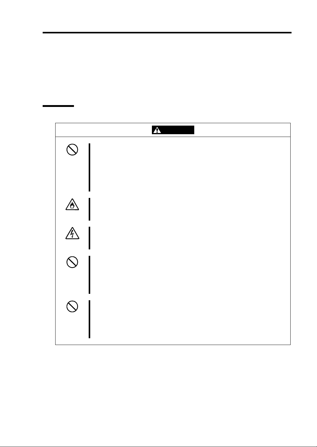
This guide uses the following three types of symbols to give indications and precautions against a
danger. They are defined as follows:
Indicates that there is a risk of danger. Each image symbolizes a particular type of
danger. (Attention)
Indicates what you must not do. Each image symbolizes a particular type of
prohibition. (Prohibited actions)
Indicates what you must do. Each image symbolizes a particular type of action
necessary to avoid a danger. (Mandatory actions)
(Example)
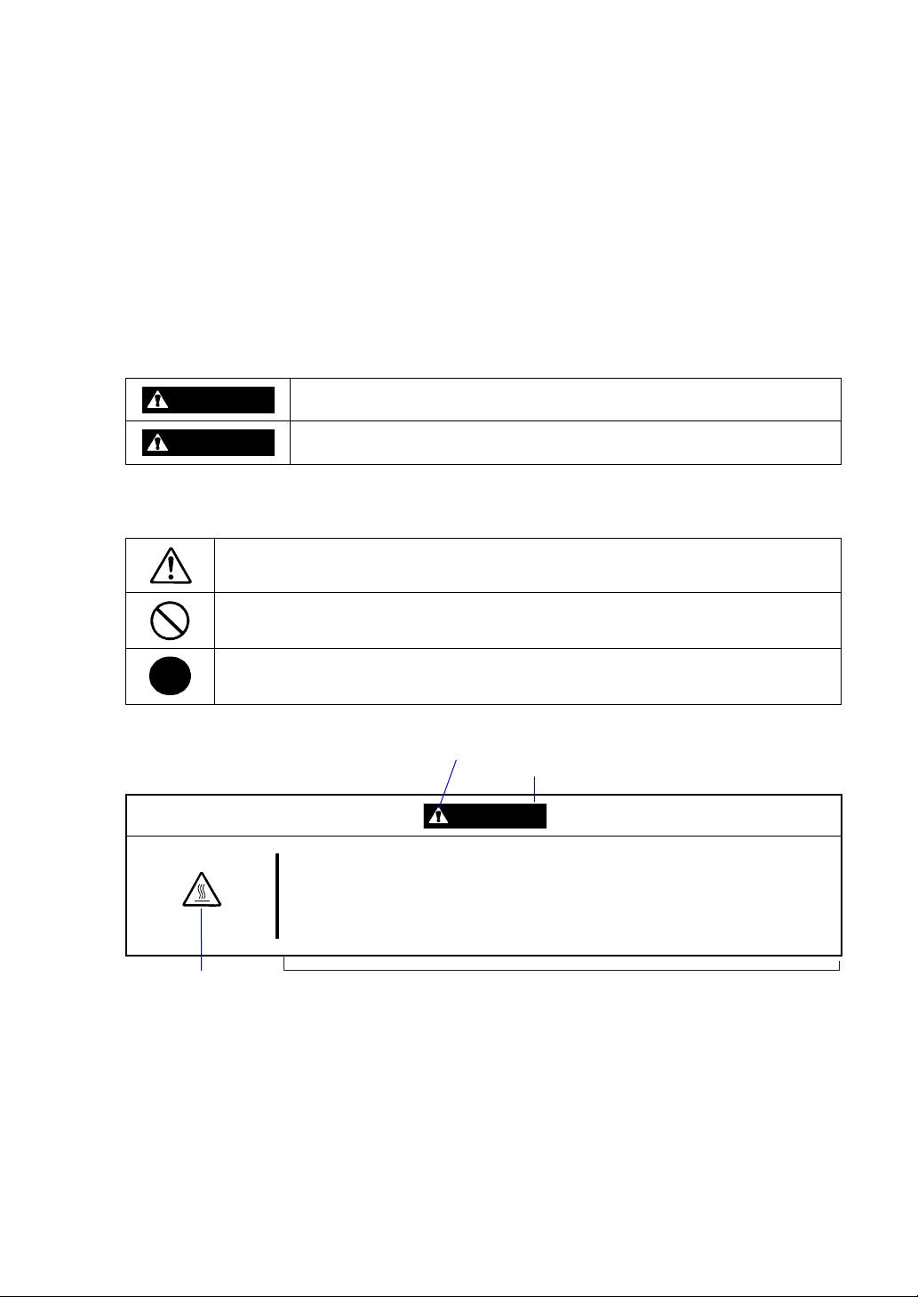
Term indicating a degree of danger
High temperature.
Indicates a danger that could lead to a burn, other injuries or damage to
physical assets.
Symbol to draw attention
CAUTION
Immediately after the power-off, system components such as hard disk drive
are very hot. Wait the server to cool down completely before adding/removing
some component.
Symbol indicating a prohibited
action (may not always be
indicated)
Description of a danger
Page 4
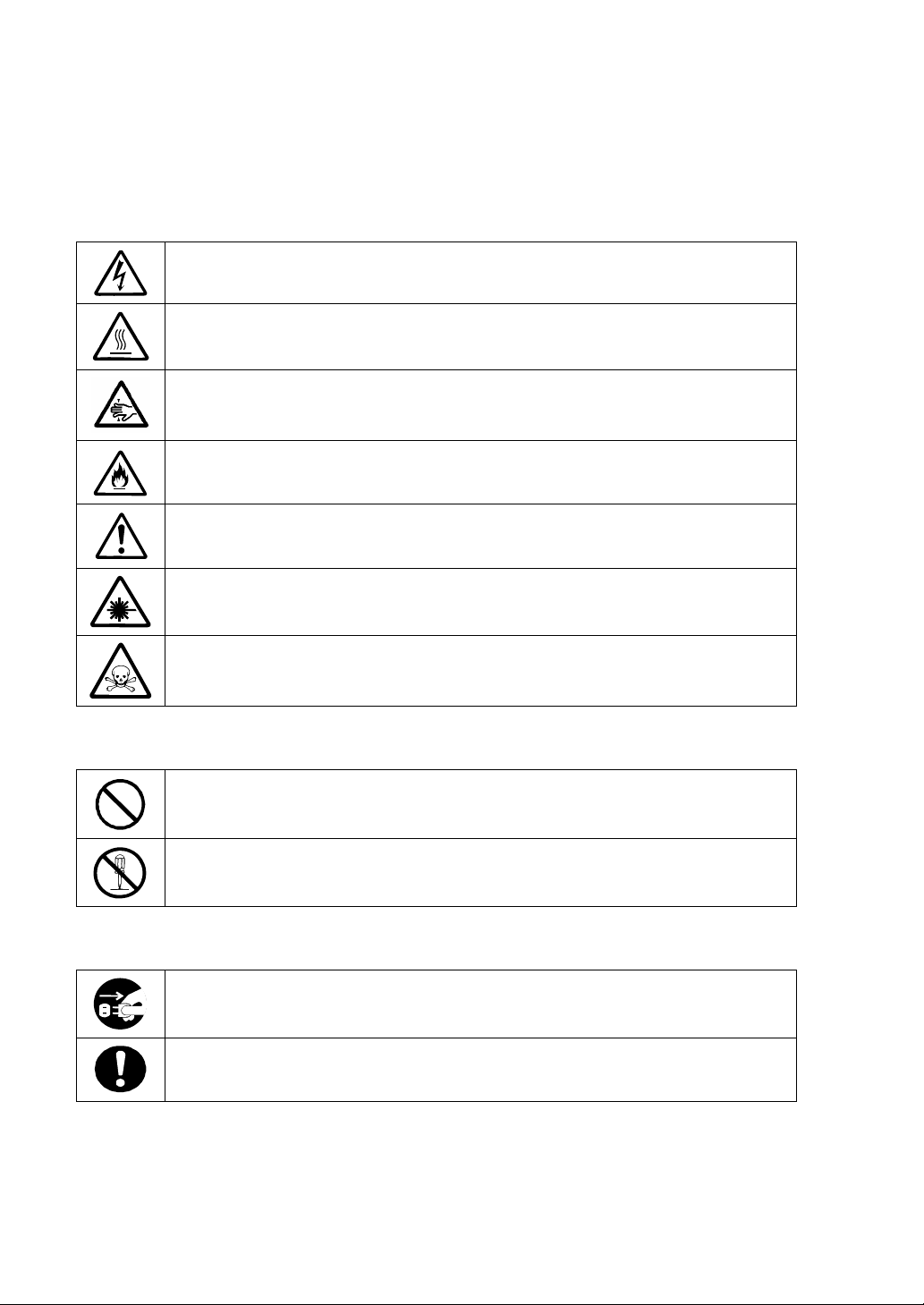
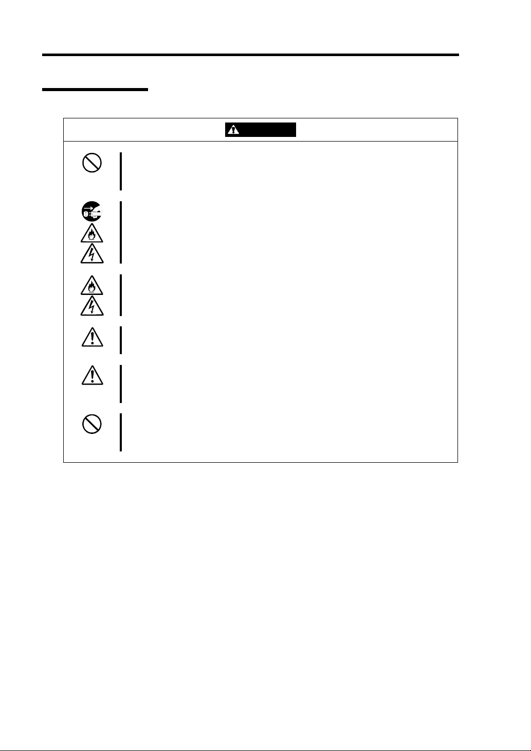
SYMBOLS USED IN THIS USER'S GUIDE AND WARNING LABELS
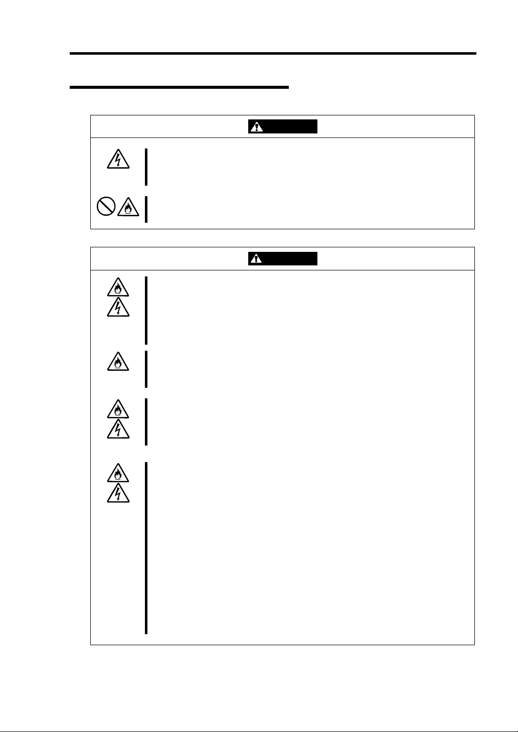
Attention
Indicates a risk of an electric shock.
Indicates a risk of an injury due to heat.
Indicates a risk of catching your fingers.
Indicates a risk of a fire or smoke.
Indicates a general precaution or warning that is not defined herein.
Indicates a risk of losing eyesight due to laser beam.
Indicates a risk of an injury or damage to physical assets due to hazardous material.
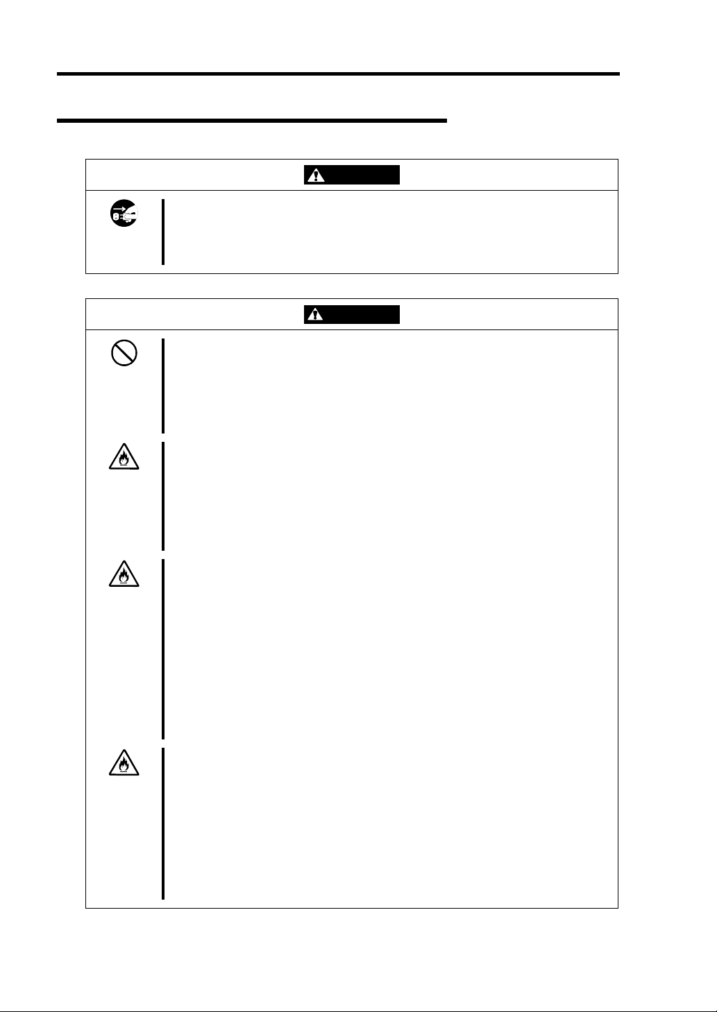
Prohibited actions
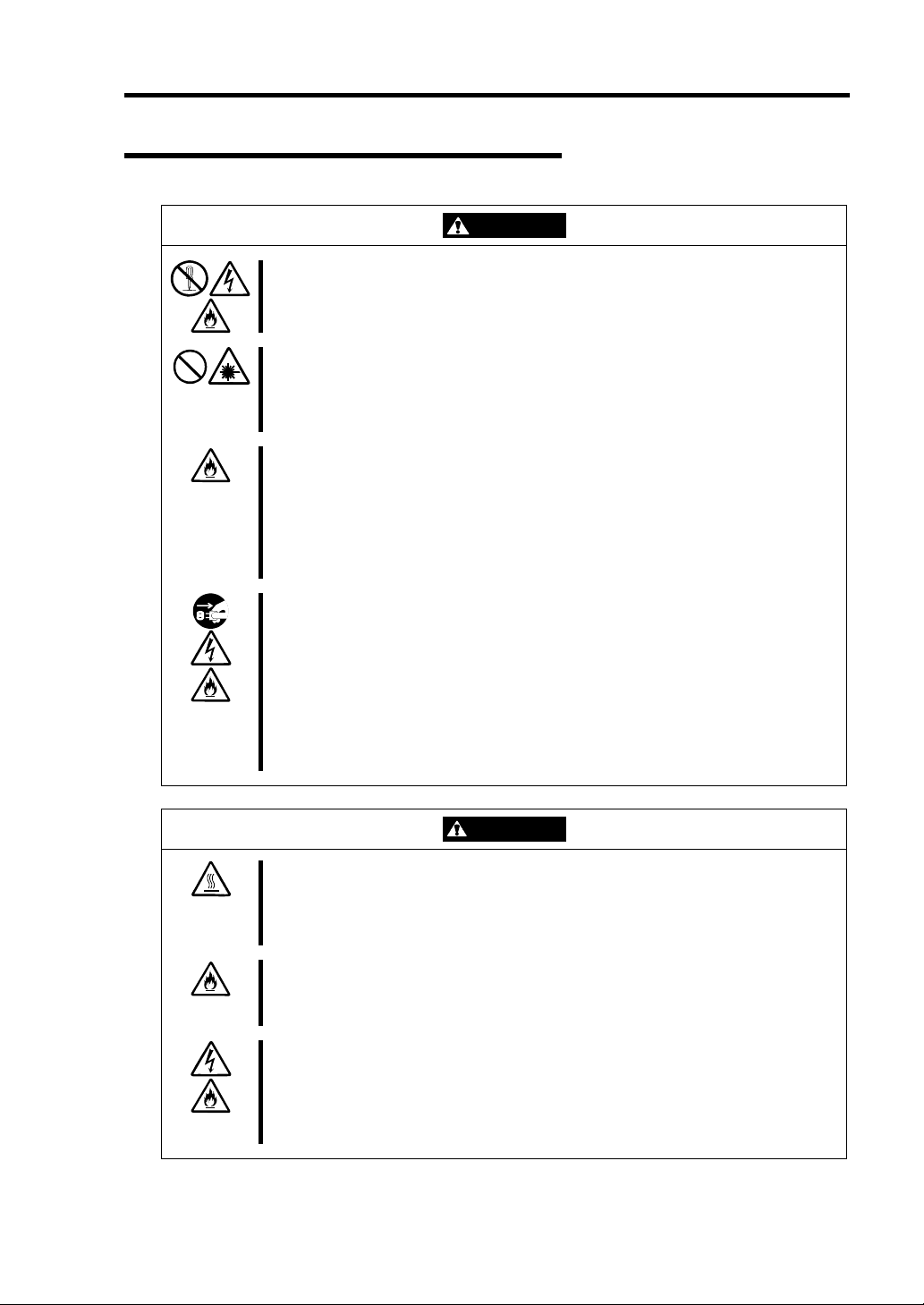
Indicates a general prohibition that is not defined herein.
Do not disassemble, repair, or modify the equipment. There is a risk of an electric
shock or fire.
Mandatory actions
Unplug the server. There is a risk of an electric shock or fire.
Indicates a general action to take that is not defined herein. Make sure to follow the
instructions.
Page 5

NOTE: This equipment has been tested and found to comply with the limits for a Class A digital
device, pursuant to Part 15 of the FCC Rules. These limits are designed to provide reasonable
protection against harmful interference when the equipment is operated in a commercial
environment. This equipment generates, uses, and can radiate radio frequency energy and, if not
installed and used in accordance with the instruction manual, may cause harmful interference to
radio communications. Operation of this equipment in a residential area is likely to cause harmful
interference in which case the user will be required to correct the interference at his own expense.
This class A digital apparatus meets all requirements of the Canadian Interference-Causing
Equipment Regulations.
Cet appareil numériqeu de la classe A respecte toutes les exigences du Règlement sur le matériel
brouilleur du Canada.
CE Statement
Warning: This is a Class A product. In residential environment, this product may cause radio
interference, in which case the user may be required to take adequate measures (EN55022).
NOTE: This product provides resistance against hardware faults with its redundant hardware
modules. However, this does not mean complete fault-tolerance is assured. For example,
there is a risk of system down when:
– A fatal fault occurs in software.
– Both modules within a redundant hardware pair break down.
– A fatal fault occurs in a non-redundant component, such as the clock generator circuitry
or the interconnect backplane.
– The entire system is cut off from AC power.
Page 6

Trademarks
NEC EXPRESSBUILDER, NEC ESMPRO, and NEC Express5800/ft series are trademarks of NEC
Corporation. Stratus is a registered trademark of Stratus Technologies Bermuda Ltd. Microsoft, Windows,
Windows Server, Windows NT, and MS-DOS are registered trademarks or trademarks of Microsoft
Corporation in the United States and other countries. Intel and Pentium are registered trademarks of Intel
Corporation. Xeon is a trademark of Intel Corporation in the United States. AT is a registered trademark of
International Business Machines Corporation in the United States and other countries. Adobe, the Adobe logo,
Acrobat, and the Acrobat logo are trademarks of Adobe Systems Incorporated. Datalight is a registered
trademark of Datalight, Inc. ROM-DOS is a trademark of Datalight, Inc. DLT and DLTtape are trademarks of
Quantum Corporation in the United States. QLogic and its logo are trademarks of QLogic Corporation in the
United States. Fast!UTIL is a trademark of QLogic Corporation in the United States.
All other product, brand, or trade names used in this publication are the trademarks or registered trademarks of
their respective trademark owners.
Microsoft Windows Server 2003 Standard Edition operating system and Microsoft Windows Server 2003
Enterprise Edition operating system are called Windows Server for short. Microsoft Windows 2000 Server
operating system, Microsoft Windows 2000 Advanced Server operating system and Microsoft Windows 2000
Professional operating system are called Windows 2000 for short. Microsoft Windows NT Server network
operating system version 3.51/4.0 and Microsoft Windows NT Workstation operating system version 3.51/4.0
are called Windows NT for short. Microsoft Windows Millennium Edition Operating System is called
Windows Me for short. Microsoft Windows 98 operating system is called Windows 98 for short. Microsoft
Windows 95 operating system is called Windows 95 for short.
Names used with sample applications are all fictitious. They are unrelated to any existing product names,
names of organizations, or individual names.
To prevent voltage sag:
This product may be affected by voltage sag caused due to lightning. To prevent voltage sag, you
are recommended to use an AC uninterruptible power supply (UPS) unit.
Notes:
(1) No part of this manual may be reproduced in any form without prior written permission of NEC
Corporation.
(2) The contents of this manual are subject to change without prior notice.
(3) The contents of this manual shall not be copied or altered without prior written permission of NEC
Corporation.
(4) All efforts have been made to ensure the accuracy of all information in this manual. If you find any part
unclear, incorrect, or omitted in this manual, contact the sales agent where you purchased this product.
(5) NEC assumes no liability arising from the use of this product, nor any liability for incidental or
consequential damage arising from the use of this manual regardless of (4) above.
Page 7

PREFACE
Welcome to the NEC Express5800/ft series.
NEC Express5800/ft series is a "fault-tolerant (ft)" server focusing on "high reliability" in terms of
fault-tolerance, in addition to "high performance," "scalability," and "general versatility" provided
by NEC Express5800 series. In the event of trouble, its dual configuration will allow the system to
instantaneously isolate the failed parts to assure non-stop running; operation will be moved
smoothly from one module to the other, minimizing damage to it. You can use this NEC
Express5800/ft series in a mission-critical system where high availability is required. By the use of
Windows operati ng system, it also provides outstanding openness fo r gen eral -p u rpose appl i cat i ons ,
etc.
To make the best use of these features, read this User's Guide thoroughly to understand how to
operate NEC Express5800/ft series.
i
Page 8

ii
ABOUT THIS USER'S GUIDE
This User's Guide helps a user to properly setup and use the product.
Consult this guide to ensure safety as well as to cope with trouble during a system setup and daily
operation.
Keep this manual handy.
This User's Guide is intended for users who have a goo d kn owl e dge on the basic use of Windows
operating systems and general I/O devices such as a keyboard and mouse.
How to Use This User's Guide
This guide consists of eight chapters and appendices. To help you find a solution quickly, the guide
contains the following information:
For descriptions on setting up this product, see the separate volume "User’s Guide (Setup)".
Read "Precautions for Use" first.
Before going on to main chapters, be sure to read "Precautions for Use." These precautions are very
important for using the product safely.
Chapter 1 Precautions for Use
This chapter describes precautions necessary to use the product safely and properly. Be sure to
read this chapter before using the product. It also provides information on user support. It will be
helpful when you need maintenance service, support, etc.
Chapter 2 General Description
This chapter describes what you should know about the product: its component names, functions,
operating procedures as well as handling of devices and other parts.
Chapter 3 Windows Setup and Operation
This chapter describes setup and operation specific to the product when it is on Windows.
Chapter 4 System Configuration
This chapter describes how to make settings of built-in basic input/output system. It also describes
factory-shipped parameters.
Chapter 5 Installing and Using Utilities
This chapter describes features and operating procedures of a standard utility "NEC
EXPRESSBUILDER." It also describes procedures to install and operate various software
programs contained in its CD-ROM.
Chapter 6 Maintenance
This chapter describes maintenance procedures and use of maintenance tools. If you need to
move the product for maintenance purposes, follow the steps provided in this chapter.
Chapter 7 Troubleshooting
If the product does not work properly, see this chapter before deciding that it is a breakdown.
Chapter 8 Option
This chapter describes options available for the server, procedures and precautions for replacing
the failed devices.
Appendix A Specifications
This appendix lists specifications of the product.
Appendix B IRQ and I/O Port Address
This appendix lists factory-assigned IRQ and I/O port address.
Page 9

Additional symbols
The following symbols are used throughout this User's Guide in addition to the caution symbols
describe at the beginning.
iii
IMPORTANT:
CHECK:
TIPS:
Important points or instructions to keep in mind when using the
server or software
Something you need to make sure when using the server of
software
Helpful information, something useful to know
Accessories
This product is shipped with various accessories. See the attached list to make sure everything is
included and check the individual items. If some component is missing or damaged, contact your
sales agent.
Keep the accessories in a safe place. You will need them when you perform setup,
addition of options, or replacement of failed components.
NEC EXPRESSBUILDER, an accessory of the server, is packaged in a paper envelope.
For the components in the package, see the packing list of the NEC EXPRESSBUILDER
contained in the paper envelope. If you lose the NEC EXPRESSBUILDER CD-ROM and
desire to purchase a new one, contact your sales representative.
Be sure to fill out and mail the software registration card that is attached to your operating
system.
Make backup copies of included floppy disks, if any. Keep the original disks as the master
disks; use these copies in operation.
Improper use of an included floppy disk or CD-ROM may alter your system environment.
If you find something unclear, stop using them and contact your sales agent.
Page 10

iv
CONTENTS
PREFACE...........................................................................................................................i
ABOUT THIS USER'S GUIDE........................................................................................ii
CONTENTS .....................................................................................................................iv
Chapter 1 Precautions for Use ....................................................................... 1-1
WARNING LABELS .....................................................................................................1-2
Server Chassis.............................................................................................................1-2
CPU Module...............................................................................................................1-4
PCI Module.................................................................................................................1-5
Expansion PCI Module...............................................................................................1-7
PRECAUTIONS FOR SAFETY....................................................................................1-9
General .......................................................................................................................1-9
Use of Power Supply and Power Cord..................................................................... 1-11
Installation, Relocation, Storage and Connection.....................................................1-12
Cleaning and Handling of Internal Devices..............................................................1-13
During Operation......................................................................................................1-14
Rack-mount Model...................................................................................................1-15
For Proper Operation................................................................................................1-17
TRANSFER TO THIRD PARTY.................................................................................1-19
DISPOSAL OF EQUIPMENT AND CONSUMABLES.............................................1-20
IF SYSTEM TROUBLE IS SUSPECTED...................................................................1-21
ABOUT REPAIR PARTS.............................................................................................1-21
ABOUT OUR WEB SERVICE ...................................................................................1-21
Chapter 2 General Description ....................................................................... 2-1
STANDARD FEATURES..............................................................................................2-2
HOW THE OPERATING SYSTEM SEES THE CPU MODULES..............................2-6
How CPU modules appear on Device Manager.........................................................2-6
How CPU modules appear on T ask Manager.............................................................2-6
NAMES AND FUNCTIONS OF COMPONENTS.......................................................2-7
Front View (with Front Bezel Removed) ...................................................................2-7
Rear V iew...................................................................................................................2-9
CPU Module............................................................................................................. 2-11
PCI Module...............................................................................................................2-12
CD- ROM Drive.......................................................................................................2-13
Expansion PCI Module.............................................................................................2-14
Chassis Board Layout...............................................................................................2-15
LEDs.........................................................................................................................2-16
BASIC OPERATION ...................................................................................................2-28
Installing/Removing the Front Bezel........................................................................2-28
Power ON.................................................................................................................2-30
Power OFF................................................................................................................2-31
Page 11

v
Power-On Self Test (POST) ..................................................................................... 2-32
Floppy Disk Drive.................................................................................................... 2-35
CD-ROM Drive........................................................................................................ 2-38
Chapter 3 Windows Setup and Operation......................................................3-1
DISK OPERATIONS..................................................................................................... 3-2
Disks Operations Using Disk Management ............................................................... 3-3
Disk Operations Using the RDR (Rapid Disk Resync) Function............................. 3-15
Replacing Failed Hard Disk Drives.......................................................................... 3-25
CHANGE DRIVE LETTER........................................................................................ 3-33
DUAL LAN CONFIGURATION ................................................................................3-34
Overview.................................................................................................................. 3-34
Configuring dual LAN .............................................................................................3-34
Removing dual LAN................................................................................................ 3-37
CHECK THE DUPLICATING OPERATION OF MODULES................................... 3-40
Evaluate Startup and Stop of PCI Modules.............................................................. 3-40
Evaluate Start and Stop of CPU Modules ................................................................ 3-43
Evaluate Start and Stop of Expansion PCI Modules................................................ 3-45
NEC Express5800/ft series SERVICE PROGRAM CONFIGURATION ................... 3-47
Chapter 4 System Configuration.....................................................................4-1
SYSTEM BIOS ~ SETUP ~........................................................................................... 4-2
Starting SETUP Utility............................................................................................... 4-3
Description of On-Screen Items and Key Usage........................................................ 4-4
Menu and Parameter Descriptions ............................................................................. 4-5
SCSI BIOS ∼ Fast!UTIL ∼........................................................................................... 4-21
Setting List for Optional SCSI Device..................................................................... 4-31
RESET AND FORCED SHUTDOWN........................................................................4-32
Resetting the Server.................................................................................................. 4-32
Forced Shutdown...................................................................................................... 4-32
Clear CMOS / Password (Configuring Motherboard Jumpers) ...............................4-33
Chapter 5 Installing and Using Utilities..........................................................5-1
NEC EXPRESSBUILDER............................................................................................. 5-2
Start Menu.................................................................................................................. 5-2
NEC EXPRESSBUILDER Top Menu .......................................................................5-4
Master Control Menu ................................................................................................. 5-7
NEC ESMPRO Agent AND Manager............................................................................ 5-8
Overview.................................................................................................................... 5-8
NEC ESMPRO Agent.............................................................................................. 5-16
NEC ESMPRO Manager.......................................................................................... 5-25
Maintenance of NEC Express5800/ft series ............................................................. 5-46
Page 12

vi
Chapter 6 Maintenance.................................................................................... 6-1
DAILY MAINTENANCE..............................................................................................6-2
Checking Alert............................................................................................................6-2
Checking STATUS LEDs ...........................................................................................6-3
Making Backup Copies ..............................................................................................6-3
Cleaning......................................................................................................................6-4
SYSTEM DIAGNOSTICS (CONSUMER)...................................................................6-7
Test Items....................................................................................................................6-7
Startup and Exit of System Diagnosis (Consumer)....................................................6-7
OFF-LINE MAINTENANCE UTILITY .......................................................................6-9
RELOCATING/STORING THE NEC Express5800/ft series......................................6-10
Chapter 7 Troubleshooting ............................................................................. 7-1
TO LOCATE THE ERRORS .........................................................................................7-2
ERROR MESSAGES.....................................................................................................7-3
Error Messages by LED Indication ............................................................................7-3
Windows Server 2003, Enterprise Edition Error Messages........................................7-4
Server Management Application Error Message........................................................7-5
SOLVING PROBLEMS.................................................................................................7-6
Problems with NEC Express5800/ft series.................................................................7-6
Problems with NEC EXPRESSBUILDER...............................................................7-19
Problems with Master Control Menu .......................................................................7-20
Problems with NEC ESMPRO.................................................................................7-21
COLLECTION OF TROUBLE LOGS ........................................................................7-29
Collection of Event Logs..........................................................................................7-30
Collection of Configuration Information..................................................................7-31
Collection of Diagnostic Information by Dr. Watson...............................................7-31
COLLECTION OF THE MEMORY DUMP ...............................................................7-32
Chapter 8 Option.............................................................................................. 8-1
SAFETY PRECAUTIONS.............................................................................................8-2
ANTI-STATIC MEASURES..........................................................................................8-3
PREPARING YOUR SYSTEM FOR UPGRADE.........................................................8-4
OPTIONS .......................................................................................................................8-5
3.5-INCH HARD DISK DRIVE ....................................................................................8-6
Installing 3.5-inch Hard Disk Drive ...........................................................................8-8
Removing 3.5-inch Hard Disk Drive........................................................................ 8-11
Replacing 3.5-inch Hard Disk Drive........................................................................8-12
PROCESSOR ...............................................................................................................8-13
DIMM...........................................................................................................................8-14
PCI BOARD.................................................................................................................8-15
SETUP OF OPTIONAL PCI BOARD .........................................................................8-16
N8804-001P1 100BASE-TX Adapter Set ................................................................8-17
N8803-031F Fibre Channel Controller.....................................................................8-19
N8104-84 1000BASE-SX Adapter...........................................................................8-23
Page 13

vii
N8104-103 1000BASE-T Adapter ........................................................................... 8-25
Supplement ............................................................................................................... 8-27
Appendix A Specifications..............................................................................A-1
Appendix B IRQ and I/O Port Address...........................................................B-1
Interrupt Request........................................................................................................B-1
I/O Port Address.........................................................................................................B-2
Page 14

viii
(This page is intentionally left blank.)
Page 15

Chapter 1
Precautions for Use
This chapter includes information necessa ry fo r pr o per and safe operation of the server.
Page 16
1-2 Precautions for Use
WARNING LABELS
Warning labels are placed in certain parts of the system so that the user stays alert to possible risks
(Do not remove or damage these labels).
If some label is missing, about to peel off, or illegible, contact your sales agent.
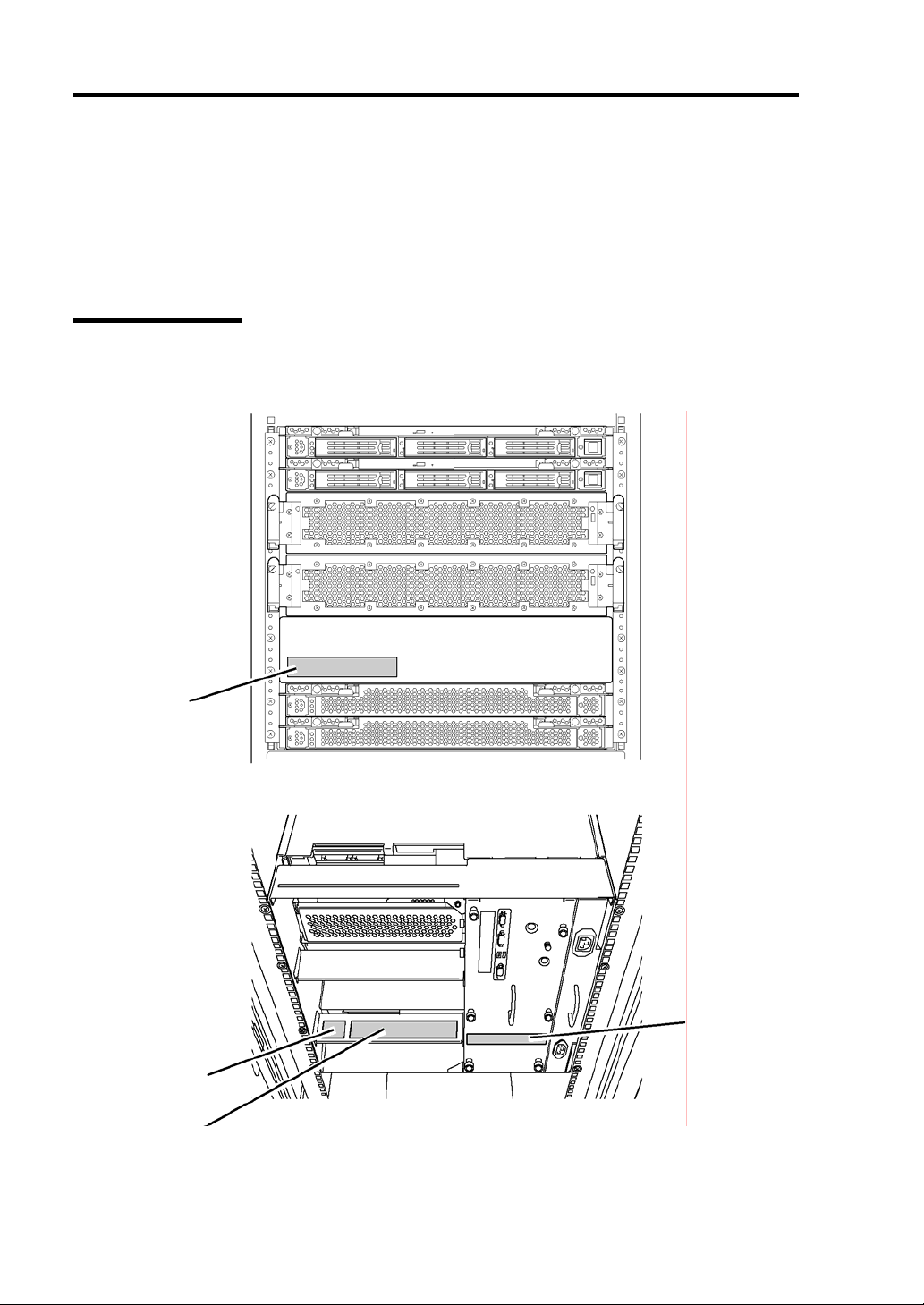
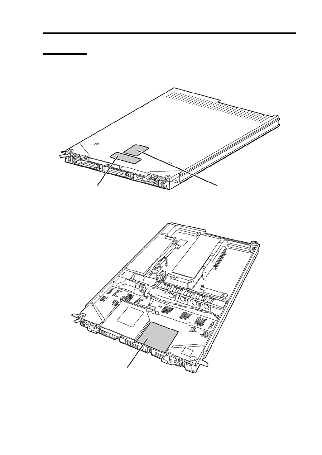
Server Chassis
The figures below show locations of the labels on the server chassis.
Label A
Label D
Label B
Label C
Page 17

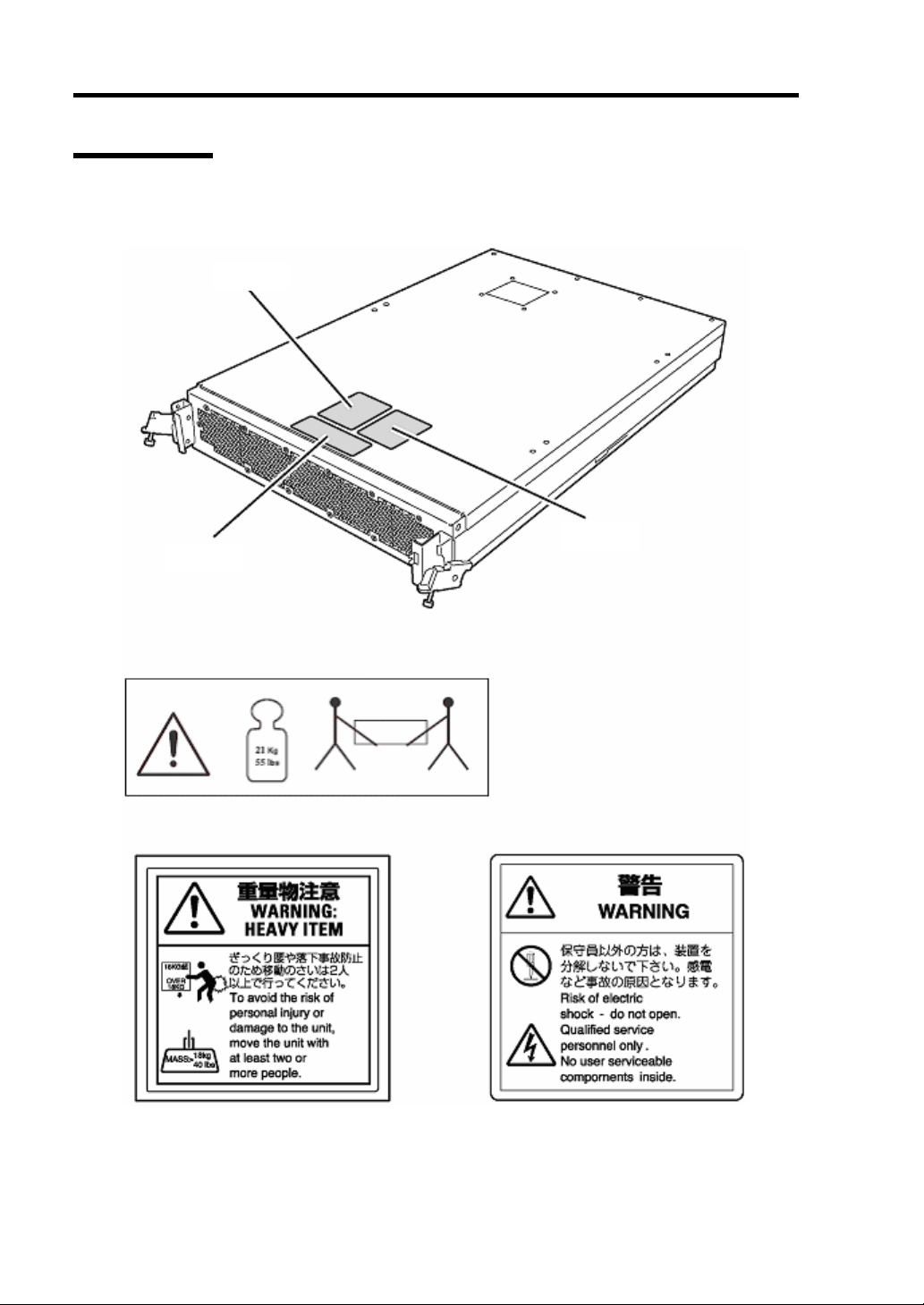
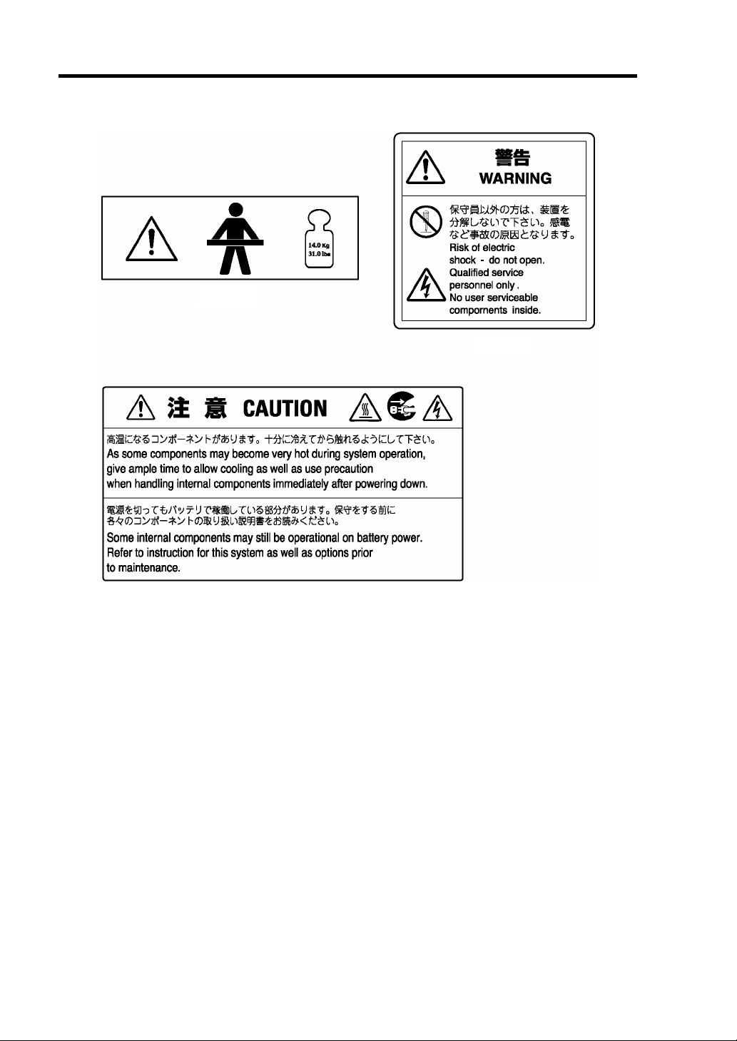
Label A
Label B
Label C
Precautions for Use 1-3
Label D
Page 18
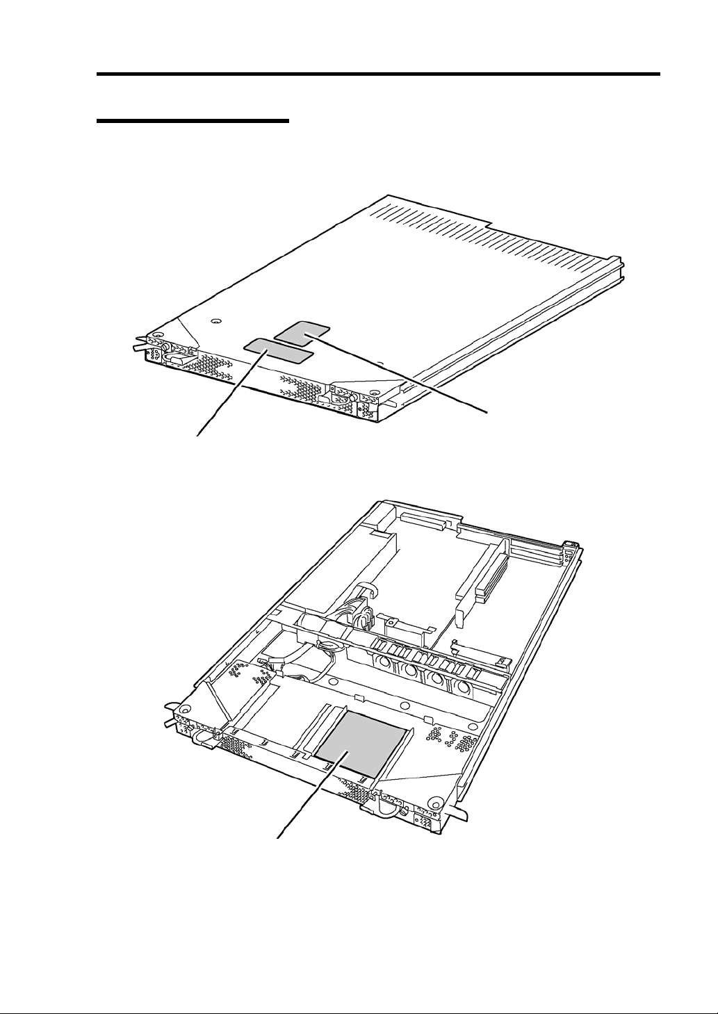
1-4 Precautions for Use
CPU Module
The figures below show locations of the labels on CPU module:
Label B
Label A
Label C
Label A
Label B Label C
Page 19
PCI Module
The figures below show locations of the labels on PCI module:
External View
Precautions for Use 1-5
Label A
Internal View
Label C
Label B
Page 20
1-6 Precautions for Use
Label A
Label B
Label C
Page 21
Precautions for Use 1-7
Expansion PCI Module
The figure below shows locations of the labels on expansion PCI module:
External View
Label B
Label A
Internal View
Label C
Page 22
1-8 Precautions for Use
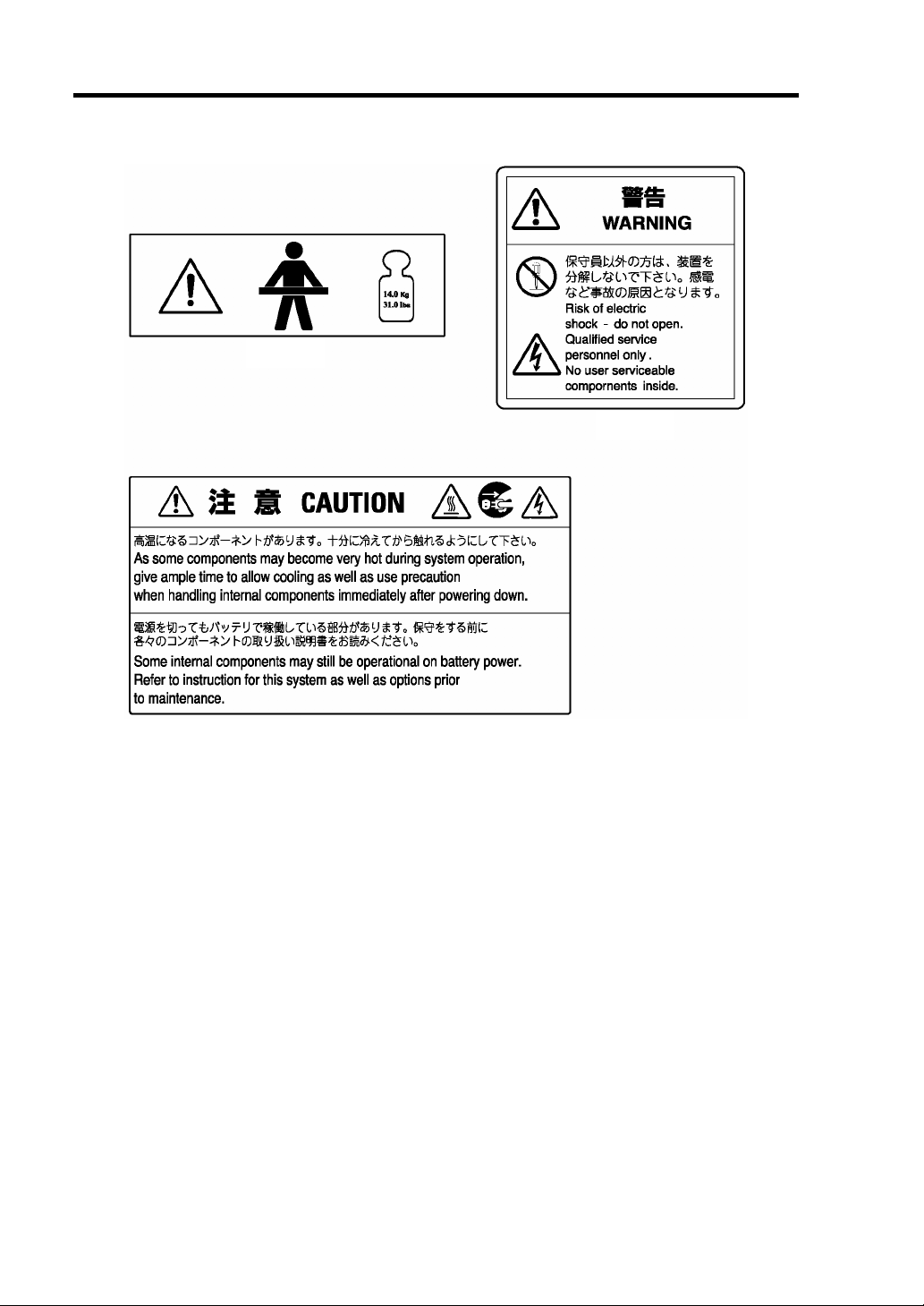
Label A
Label B
Label C
Page 23
Precautions for Use 1-9
PRECAUTIONS FOR SAFETY
This section provides precautions for using the server safely. Read this section carefully to ensure
proper and safe use of the server. For symbol meanings, see "SAFETY INDICATIONS" described
in the previous section.
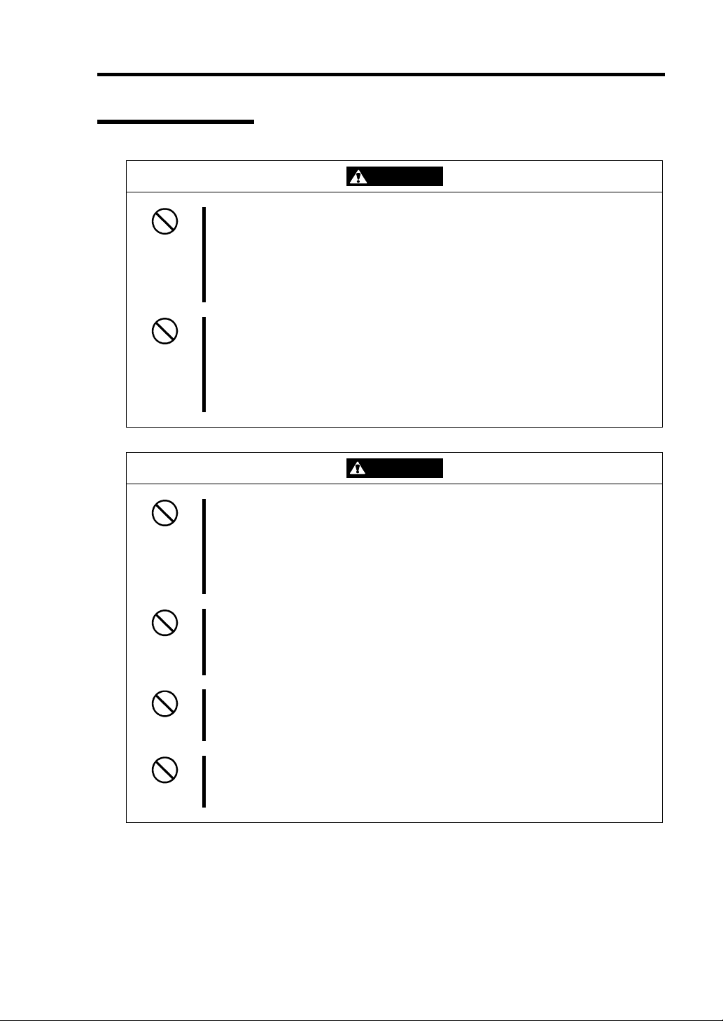
General
This equipment is not intended for use in controlling or use with facilities or
WARNING
Do not use the equipment in an operation where human lives are involved or
high reliability is required.
systems where human lives are involved or high reliability is required, inc luding
medical devices or nuclear, aerospace, transportation, and traffic control
facilities. NEC assumes no liability for any accidents or damage to physical
assets resulting from the use of this equipment in such systems or facilities.
Do not continue to use the equipment if you detect smoke, odor, or noise.
If the equipment emits smoke, odor, or noise, immediately turn off the server,
unplug the cord, and contact your sales agent. There is a risk of a fire.
Do not insert a wire or metal object
Do not insert a wire or metal objects into a vent or disk drive slot. There is a risk
of an electric shock.
Do not use the equipment in an unsuitable place.
Do not install a server rack in an unsuitable environment. Other systems also
may be affected and the rack may fall over to cause a fire or injuries. For details
about installation environment and quake-resistant engineering, see the
attached manual or contact your sales agent.
Do not install the equipment on a nonconforming rack.
Install the equipment on a 19-inch rack confirming to the EIA standard. Do not
use the equipment without a rack or install it on a nonconforming rack. The
equipment may not function properly, and there is a risk of damage to physical
assets or injuries. For suitable racks, contact your sales agent.
Page 24

1-10 Precautions for Use
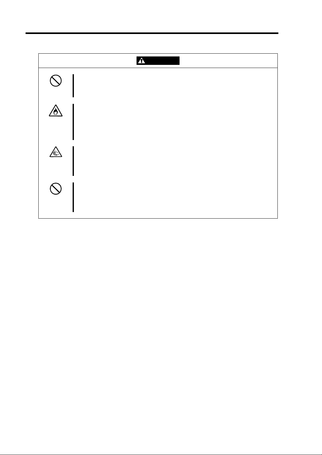
CAUTION
Prevent water or foreign objects from getting into the equipment.
Do not let water or foreign objects (e.g., pins or paper clips) enter the
equipment. There is a risk of a fire, electric shock, and breakdown. When such
things accidentally enter the equipment, immediately turn off the power and
unplug the cord. Contact your sales agent instead of trying to disassemble it
yourself.
Page 25
Use of Power Supply and Power Cord
Precautions for Use 1-11
WARNING
Do not handle a power plug with a wet hand.
Do not plug/unplug a power cord with a wet hand. There is a risk of an electric
shock.
Do not connect the ground wire to a gas pipe.
Never connect the ground wire to a gas pipe. There is a risk of a gas explosion.
CAUTION
Do not plug the cord in a nonconforming outlet.
Use a wall outlet with specified voltage and power type. There is a risk of a fire
or current leakage.
Avoid installing the equipment where you may need an extension c ord. If the
cord that does not meet the power specifications, there is a risk of overheating
that could lead to a fire.
Do not plug too many cords in a single outlet.
If the rated current is exceeded, there is a risk of overheating that could lead to
a fire.
Do not plug the cord insecurely.
Insert the plug firmly into an outlet. There is a risk of heat or fire due to poor
contact. If dust settles on the slots and it absorbs moisture, there is also a risk
of heat or fire.
Do not use the nonconforming power cords.
Use the power cords specified by NEC. If the rated current is exceeded, there is
a risk of a fire. You also have to observe the following prohibitions about
handling and connecting interface cables.
Do not stretch the cord harnes s.
Do not pinch th e power cord.
Do not bend th e power cord.
Keep chemicals away from the power cord.
Do not twist the power cord.
Do not place a ny object on the power cord.
Do not use cords as bundled.
Do not alter, modify, or repair the power cord.
Do not secure the power cord with staples or equivalents.
Do not use an y damaged power cord. (Replace a damaged power cord with
a new one of the same specifications. Ask your sales agent for
replacement.)
Page 26
1-12 Precautions for Use
Installation, Relocation, Storage and Connection
WARNING
Disconnect the power cord(s) before installing or removing the equipment.
Be sure to power off the equipment and unplug its power cords from the wall
outlet before installation/relocation. All voltage is removed only when the power
cords are unplugged.
CAUTION
Never attempt to lift the CPU module only by yourself.
The CPU module weighs approx. 21 kg (depending on its hardware
configuration). Carrying the CPU module only by yourself may strain your back.
Hold the CPU module firmly by its bottom with another person to carry it.
The PCI module and the expansion PCI module weighs approx. 14 kg
(depending its hardware configuration). Hold the module firmly by its bottom.
Do not install the equipment in an unsuitable place.
Install the equipment in such a place as specified in this User's Guide. Avoid
the following, or there is a risk of a fire.
a dust y place
a humid place located near a boiler, etc
a place exposed to direct sunlight
an unstable place
Do not use or store this product in corrosive environment.
Avoid the usage or storage of this product in an environment which may be
exposed to corrosive gases, such as those including but not limited to: sulfur
dioxide, hydrogen sulfide, nitrogen dioxide, chlorine, ammonia and/or ozone .
Avoid installing this product in an environment or one that may be exposed to
corrosive materials such as sodium chloride and/or sulfur.
Avoid installing this product in an environment which may have excessive metal
flakes or conductive particles in the air.
Such environments may cause corrosion or short circuits within this product,
resulting in not only damage to this product, but may even lead to be a fire
hazard. If there are any concerns regarding the environment at the planned site
of installation or storage, please contact your sales agent.
Do not use any non-designated interface cable.
Use only interface cables designated by NEC; identify which component or
connector to attach beforehand. If you use a wrong cable or make a wrong
connection, there is a risk of short-circuit that could lead to a fire.
You also have to observe the following prohibitions about handling and
connecting interface cables:
Do not use an y damaged cable connector.
Do not step on the cable.
Do not place a ny object on the cable.
Do not use the equi pment with loose cable connections.
Page 27
Cleaning and Handling of Internal Devices
Precautions for Use 1-13
WARNING
Do not disassemble, repair, or alter the server.
Unless described herein, never attempt to disassemble, repair, or alter the
equipment. There is a risk of an electric shock or fire as well as malfunction.
Do not look into the CD-ROM drive
The CD-ROM drive uses a laser beam. Do not look or insert a mirror inside
while the system is on. A laser beam is invisible; if your eyes get exposed to it,
there is a risk of losing eyesight.
Do not detach a lithium battery yourself.
This equipment has a lithium battery. Do not detach it yourself. If the battery is
exposed to fire or water, it could explode.
When the lithium battery is running down and the equipment doesn’t work
correctly, contact your sales agent instead of disassembling, replacing or
recharging it yourself.
Disconnect the power plug before cleaning the server.
Make sure to power off the server and disconnect the power plug from a power
outlet before cleaning or installing/removing internal optional devices. Touching
any internal device of the server with its power cord connected to a power
source may cause an electric shock even of the server is off-powered.
Disconnect the power plug from the outlet occasionally and clean the plug with
a dry cloth. Heat will be generated if condensation is formed on a dusty plug,
which may cause a fire.
CAUTION
High temperature
Immediately after powering off the system, system components such as hard
disk drive may be very hot. Wait for the server to cool down completely before
adding/removing components.
Make sure to complete installation.
Firmly install all power cords, interface cables and/or boards. An incompletely
installed component may cause a contact failure, resulting in fire and/or smoke.
Protect the unused connectors with the protective cap.
The unused power cord connectors are covered with the protective cap to
prevent short circuits and electrical hazards. When removing the power cord
connector from the internal devices, attach the protective cap to the connector.
Failure to follow this warning may cause a fire or an electric shock.
Page 28
1-14 Precautions for Use
During Operation
CAUTION
Do not pull out a device during operation.
Do not pull out or remove a device while it works. There is a risk of malfunction
and injuries.
Do not touch the equipment when it thunders.
Unplug the equipment when it threatens to thunder. If it starts to thunder before
you unplug the equipment, do not touch the equipment and cables. There is a
risk of a fire or electric shock.
Keep animals away.
Animal’s waste or hair may get inside the equipment to cause a fire or electric
shock.
Do not place any object on top of the server.
The object may fall off to cause injuries, damage to hardware and/or a fire.
Do not leave the CD tray ejected.
Dust may get in the equipment to cause malfunction. The ejected tray may also
become a cause of injuries.
Do not use a cellular phone or pager around the equipment.
Turn off your cellular phone or pager when you use the equipment. Their radio
waves may cause the equipment to malfunction.
Page 29
Rack-mount Model
Precautions for Use 1-15
WARNING
Do not use the equipment in an unsuitable place.
Do not install a server rack in an unsuitable environment.
Otherwise, other systems also may be affected, and the rack may fall over to
cause a fire or injuries. For details about installation environment and
quake-resistant engineering, see the attached manual or contact your sales
agent.
Do not install the equipment on a nonconforming rack.
Install the equipment on a 19-inch rack confirming to the EIA standard. Do not
use the equipment without a rack or install it on a nonconforming rack.
Otherwise, the equipment may not function properly, and there is a risk of
damage to physical assets or injuries. For suitable racks, contact your sales
agent.
CAUTION
Do not carry or install the server only by a single person.
More than one person is required to carry or install the rack. Failure to follow
this instruction may cause the rack to fall to result in personal injury and/or
breakage of surrounding devices. In particular, a high rack (such as 44U rack)
is unstable if it is not fixed by stabilizers. More than one person must always
carry or install the rack while they support it.
Do not install the equipment in such a manner that its weight is imposed on a
single place.
To distribute the weight, attach stabilizers or install two or more racks.
Otherwise, it may fall down to cause injuries.
Do not assemble parts alone.
It takes at least two people to mount doors and trays to a rack. Otherwise, you
may drop some parts to cause a breakage or injuries.
Do not pull a device out of the rack if it is unstable.
Before pulling out a device, make sure that the rack is fixed (by stabilizers or
quake-resistant engineering).
Page 30
1-16 Precautions for Use
CAUTION
Do not leave two or more devices pulled out from the rack.
If you pull out two or more devices the rack may fall down. You can only pull out
one device at a time.
Do not install excessive wiring.
To prevent burns, fires, and damage to the equipment, make sure that the rated
load of the power branch circuit is not exceeded. For more information on
installation and wiring of power-related facilities, contact your electrician or local
power company.
Do not pinch your finger with rails or other components.
Note sufficiently that your fingers may not be caught between a rail and another
mechanical part or cut by a rail at installation or removal of the server from the
rack.
Do not pull out or remove the server from the rack while it is operating.
Do not pull out or remove the server from the rack while it is operating. Doing
so may cause not only the server to operate incorrectly but also the server to
fall on people to make them injured.
Page 31

Precautions for Use 1-17
For Proper Operation
Observe the following instructions for successful operation of the server. Failure to observe them
could lead to malfunction or breakdown.
Perform installation in a place where the system can operate correctly. For details, see the
separate volume “User's Guide (Setup)”.
Before turning off the power or ejecting a disk, make sure that the DISK LED is off.
When you have just turned off the power, wait at least 30 seconds before turning it on
again.
Once you have turned on the server, do not turn it off until the "NEC" logo appears on the
screen.
Before you move the equipment, turn off the power and unplug the cord.
This server shall not assure reproduction of copy-protect CDs using reproduction
equipment if such disks do not comply with CD standards.
Clean the equipment regularly. (For procedures, see Chapter 6.) Regular cleaning is
effective in preventing various types of trouble.
Lightning may cause voltage sag. As a preventive measure, it is recommended to use UPS
(uninterruptible power supply).
This equipment does not support the connection through an UPS serial port (RS-232C) or
the control using PowerChutePlus.
Check and adjust the system clock before operation in the following conditions:
- After transporting the equipment
- After storing the equipment
- After the equipment halt under the conditions which is out of the guaranteed
environment conditions (Temperature: 10 to 35°C, Humidity: 20 to 80%).
Check the system clock once in a month. It is recommended to operate the system clock
using a time server (NTP server) if it is installed on the system which requires high level
of time accuracy. If the system clock goes out of alignment remarkably as time goes by,
though the system clock adjustment is performed, contact your sales agent.
When you store the equipment, keep it under storage environment conditions
(Temperature: -10 to 55°C, Humidity: 20 to 80%, non-condensing).
If NEC Express5800/ft series, the built-in optional devices, and the media set for the
backup devices (tape cartridges) are moved from a cold place to a warm place in a short
time, condensation will occur and cause malfunctions and breakdown when these are used
in such state. In order to protect important stored data and assets, make sure to wait for a
sufficient period of time to use the server or components in the operating environment.
Reference: Length of the time effective at avoiding condensation in winter (more than
10°C differences between room temperature and atmospheric temperature)
Disk devices: Approximately 2-3 hours
Tape media: Approximately 1 day
Use the UPS having "Auto-return feature" that protects the UPS from rush current
generated at startup of the device by switching to bypass circuit with no voltage drop.
However, if the power supply failed while switching to a bypass circuit (for tens of
seconds), the normal operation of the device will not be guaranteed.
Make sure that your options are compatible with the system. If you attach any
incompatible option, there is a risk of malfunction that could lead to a breakdown.
Page 32

1-18 Precautions for Use
It is recommended to use NEC's genuine option products. Some competitors’ products are
compatible with this server. However, servicing for trouble or damage resulting from such
a product will be charged even within the warranty period.
Page 33

Precautions for Use 1-19
TRANSFER TO THIRD PARTY
When you transfer (or sell) the product or its included items, you must observe the following:
Server
Attach this User's Guide to the server you are transferring (or selling) to a third party.
IMPORTANT: Data remaining on hard disk:
When you transfer your server, you are responsible for erasing important data stored on its
hard disk (e.g., customer information, accounting information); you must be careful to prevent
such data from leaking out to outsiders.
Even if you perform "Empty trash" on Windows operating system or execute a "format"
command to erase data superficially, the data actually remains on the hard disk. If data is not
erased completely, it could be restored by certain software and be used for unexpected
purposes.
You are strongly recommended to buy a special type of software or service to avoid such
trouble. For details, contact your sales agent.
NEC shall not be accountable for such data leakage caused by your failure to take necessary
measures.
Included Software
When you transfer or sell the included software to a third party, you must meet the following
conditions:
Transfer all of the software included with the system. Do not retain any copies.
Meet the conditions of transfer described in each software license agreement.
Uninstall untransferable programs, if any, from the server before the transfer.
Page 34

1-20 Precautions for Use
DISPOSAL OF EQUIPMENT AND CONSUMABLES
When you dispose of the main unit, hard disk drive, floppy disks, CD-ROMs, optional
boards, etc., you need to observe your local disposal rules. For details, ask your municipal
office.
IMPORTANT: For disposal (or replacement) of batteries on the board, consult
with your sales agent.
If data remains on the hard disk, backup data cartridges, floppy disks, or other
writable media (such as CD-R and CD-RW), it could be restored and reused by
outsiders. The customer is responsible for wiping out such data before disposal.
You need to exercise sufficient care to protect privacy and confidential
information.
Some of the system components have limited lifetime (e.g., cooling fans, built-in batteries,
built-in CD-ROM drive, floppy disk drive, and mouse). For stable operation, it is
recommended to replace them regularly. For lifetime of individual components and
replacing procedures, ask your sales agent.
WARNING
Do not detach a lithium battery yourself.
This equipment has a lithium battery. Do not detach it yourself. If the battery is
exposed to fire or water, it could explode.
RISK OF EXPLOSION IF BATTERY IS REPLACED WITH INCORRECT TYPE.
DISPOSE OF USED BATTERIES ACCORDING TO THE INSTRUCTIONS.
When the lithium battery is running down and the equipment doesn’t work
correctly, contact your sales agent instead of disassembling, replacing or
recharging it yourself.
SMM
Page 35

Precautions for Use 1-21
IF SYSTEM TROUBLE IS SUSPECTED
Before sending the equipment for repair, try the following:
1. Check if its power cord and connection cables are attached correctly.
2. See "Error Messages" in Chapter 7 to check if there is a relevant symptom. If yes, take
measures as instructed.
3. Certain software programs are required f or operation of NEC Express5800/ft series.
Check if these programs are properly installed.
4. Use a commercially available anti-virus program to check the server.
If the problem isn’t solved by the above actions, stop using the server and consult with your sales
agent. In this case, check LED indications of the server and alarm indications on the display, which
will serve as helpful information at the time of repair.
ABOUT REPAIR PARTS
The minimum duration of hold ing repair parts of this equipment may be different for each country,
so contact the NEC sales representatives.
If the period is not specified, the repair parts are kept for 5 years aft er di sco nti nuance of the product.
Page 36

1-22 Precautions for Use
Advice for Your Health
Prolonged use of a computer may affect your health. Keep in mind the
following to reduce stresses on your body:
Sit in a good posture
Sit on your chair with your back straight. If the desk height is appropriate,
you will slightly look down at the screen and your forearms will be parallel to
the floor. This "good" work posture can minimize muscle tension caused by
sedentary work.
If you sit in a "bad" posture—for example, sit round-shouldered or with you
face too close to the display—you may easily suffer fatigue or have your
eyesight affected.
Adjust the installation angle of Display
Most types of displays allow you to adjust the angle vertically and
horizontally. This adjustment is very important to prevent the reflection of
light as well as to make the screen more comfortable to see. Without this
adjustment, it is difficult to maintain a "good" work posture and may get tired
soon. Be sure to adjust the angle before using the display.
Adjust Brightness and Contrast
Displays allow you to adjust brightness and contrast. Optimum brightness
and contrast vary depending on the individual, age, brightness of the room,
etc; you need to make an adjustment accordingly. If the screen is too bright
or too dark, it is bad for your eyes.
Adjust the installation angle of Keyboard
Some types of keyboards allow you to adjust the angle. If you adjust the
angle to make the keyboard more comfortable to use, you can greatly
reduce stresses on your shoulders, arms, and fingers.
Clean the Equipment
Cleanliness of the equipment is very important not only for reasons of
appearance but also from the viewpoints of function and safety. Especially,
you need to regularly clean the display, which gets unclear due to the
accumulation of dirt.
Take a break when you get tired
If you feel tired, you are recommended to refresh yourself by taking a short
break or doing a light exercise.
Page 37

Chapter 2
General Description
This chapter describes what you need to know to use the NEC Express5800/ft series. Refer to this
chapter when you want to know about certain components and how to operate them.
Page 38

2-2 General Description
STANDARD FEATURES
High performance
®
・ Intel
・ High-speed Ethernet interface
・ High-speed disk access (Ultra160 SCSI
Expandability
・ Six slots of PCI bus (33MHz)
・ Six slots of expansion PCI bus (66MHz)
・ Large memory of up to 12 GB
・ Remote power-on feature
・ USB interface
High-reliability Various Features
・ Memory monitoring feature (1-bit error
・ Bus parity error detection
・ Temperature monitoring
・ Error notification
・ Built-in fan monitoring feature
・ Internal voltage monitoring feature
・ BIOS password feature
Management Utilities Easy and Fine Setup
・ NEC ESMPRO ・ NEC EXPRESSBUILDER (system setup
Xeon™ Processor MP
(1000Mbps/100Mbps/10Mbps supported)
Wide)
correction/ 2-bit error detection)
・ Graphic accelerator "CT69000" supported
・ El Torito Bootable CD-ROM (no emulation
mode) format supported
・ POWER switch mask
・ Remote power-on feature
・ AC-LINK feature
・ Consoleless feature
Self-diagnosis
・ Power On Self-Test (POST)
・ Test and Diagnosis (T&D) Utility
utility)
・ SETUP (BIOS setup utility)
・ Fast!UTIL (SCSI device utility)
Ready-to-use Fault-tolerant Feature
・ Quick cableless connection: hard disk drive,
CPU module, PCI module and expansion
PCI module (hot-swap supported)
・ Redundant modules achieved within a
system
・ Higher hardware availability by isolation of
failed module
Page 39

General Description 2-3
y
The NEC Express5800/ft series achieves fault-tolerant high-availability in a space-saving form
factor by incorporating redundant hardware module pairs in a single chassis. These modules work in
synchronous tight lockstep while constantly making comparisons with each other and detecting
anomalous diversions in operati on.
Mirrored
Memory
CPU Module #1
PCI Module #1
New fault-tolerant technology
Even if one hardware module stops, the server can continue operation with the other module. After the failed
module is replaced, the new module will obtain information from the other and resume operation.
Compare/
nc
S
CPU Module #2
PCI Module #2
Mirror
Windows software programs
Memory
Standard product
NEC Express5800/ft series is a highly fault-tolerant Windows server that achieves continuous
computing operations, data storage mirror, and continuous network connection. It allows you to run
Windows Server 2003-based applications.
NEC Express5800/ft series achieves continuous computing operations for the Windows server and
server-based applications with its redundant CPU processing and redundant memory. It assures data
redundancy through duplication of server data on an independent storage system. These features
eliminate server downtime that is usually caused by network disconnection or trouble with the I/O
controller, Eth e rnet ada pt e r o r disk d ri ve, and su pp ort o per ati on of the network and server
applications continuously. While being transparent to application software, NEC Express5800/ft
series achieves high fault-tolerance.
NEC Express5800/ft series detects status changes, errors and other events and notifies the Windows
Event Log of these events. If you use an alarm notification tool, you can configure NEC
Express5800/ft series to notify you when certain events occur.
NEC ESMPRO is installed on the system as a server management solution. NEC ESMPRO, a
GUI-based management tool, allows you to monitor, view, and configure NEC Express5800/ft
series. This tool also suppo rts both local and remote management of NEC Express5800/ft series.
Page 40

2-4 General Description
NEC Express5800/ft series main ly provides the following advantages:
Highly fault-tolerant processing and I/O subsystems
NEC Express5800/ft series use redundant hardware and software to assure server
operation even if one module suffers trouble with its processor, memory, I/O (including
trouble related to the I/O controller), disk drive, or Ethernet adapter.
Continuous network conn ection
NEC Express5800/ft series main tains continuous network connection by detecting any
trouble with the network adapter, connection, etc. If trouble occurs, the standby network
connection will take over all network traffic processing and thus securely maintain the
network system connection of NEC Express5800/ft series without losing network traffic
or client connection.
Support of multiple network connections
Since NEC Express5800/ft series can support multiple Ethernet connections, you can add
network redundant control or network tr affic cont rol.
Industry standard hardware platform
NEC Express5800/ft series uses IA (Intel Architecture)-based system hardware.
No need to modify applications
You can run Windows Server 2003-compliant applications on NEC Express5800/ft series.
Thus, unlike other highly fault-tolerant products, special API or scripts are not necessary.
Automati c mi rroring
NEC Express5800/ft series automatically maintains data as the current data.
Automatic detection and notification of faults
NEC Express5800/ft series detects and sorts out all events such as general status changes
and faults, and notifies Windows Event Log of these events.
Transparent migration
NEC Express5800/ft series constantly monitors events. If trouble occurs on NEC
Express5800/ft series’ server module, it will transparently use a redundant module of the
failed module. This feature maintains data and user access without losing application
service.
Automatic reconfiguration
When the failed module restarts after the trouble is corrected, NEC Express5800/ft series
will perform reconfiguration automatically, and if necessary, resynchronize the affected
modules. Reconfiguration can include CPU processing (e.g., CPU memory), server's
operating system (and related applications), and system data stored on the hard disks. In
most cases, NEC Express5800/ft series automatically restores redundancy of the server
modules after recovery.
Page 41

General Description 2-5
Local and remote management
NEC Express5800/ft series uses NEC ESMPRO as a server management tool. This tool
uses a GUI that enables monitoring and setting of NEC Express5800/ft series. NEC
ESMPRO can be used both locally and remotely on workstation PCs or server PCs.
Event notification function
When trouble or other events are detected on NEC Express5800/ft series, they will be
notified to Windows Event Log and saved. Therefore, you can view the log items locally
or remotely by a usual Windows procedure. Since NEC Express5800/ft series events use
unique IDs, they are easy to distinguish.
In-service repairing
You can repair or replace a failed module even if NEC Express5800/ft series is operating.
Partition structure
On this product, the first logical drive will be in the following state when the setup by
NEC EXPRESSBUILDER is complete:
Free area
Partition for operating system
* The size varies depending on the specification at setup.
CHECK: The partition for operating system is not mirrored at the time of NEC
EXPRESSBUILDER setup completion. Mirror the partition separately.
Page 42

2-6 General Description
HOW THE OPERATING SYSTEM SEES THE CPU MODULES
On NEC Express5800/ft series, the CPU modules are redundantly configured but only the
processors installed on the primary side are shown.
How CPU modules appear on Device Manager
Device Manager shows as many CPUs as the number of physical CPUs.
System with one CPU
System with two CPU
How CPU modules appear on Task Manager
Intel Xeon processor introduces a new technology called Hyper-Threading Technology. It is a
technology that makes the operating system see a single processor performing as two logical
processors.
Task Manager shows logical processors using the Hyper-Threading Technology. As shown
below, information for the processors of twice the number of physical processors is displayed.
S System with two CPUs ystem with one CPU
Page 43

General Description 2-7
NAMES AND FUNCTIONS OF COMPONENTS
Names and functions of components are shown below:
Front View (with Front Bezel Removed)
7 8910 11
1
2
3
4
5
6
Page 44

2-8 General Description
1 PCI module 10 (for group 1)
A module that includes a PCI board, LAN controller, SCSI controller, and SMM board.
2 PCI module 11 (for group 2)
A module that includes a PCI board, LAN controller, SCSI controller, and SMM board.
3 CPU module 0 (for group 1)
A module that includes a CPU (processor) and memory (DIMM).
4 CPU module 1 (for group 2)
A module that includes a CPU (processor) and memory (DIMM).
5 Expansion PCI module 13 (for group 1)
A module that includes expansion PCI board (See page 2-14.)
6 Expansion PCI module 12 (for group 2)
A module that includes expansion PCI board (See page 2-14.)
IMPORTANT: Note that upper module is module 13 and the lower module is
module 12 for expansion PCI modules.
7 POWER switch
A switch for turning on/off power to the system. The POWER switch on the primary PCI
module will be lit. Press it once to turn on power. Press it again to turn off power. Depress
the switch for more than four seconds to force the system to power down. The POWER
switch on the secondary PCI module will be unlit and will not respond until a failure in the
primary PCI module causes the secondary PCI module to assume primary functionality.
8 DISK LED (green/amber)
An LED on the hard disk drive. Blinks in green while the hard disk is accessed and turn
amber when operating in simplex mode. If one of the mirrored hard disks fails, the failed
disk’s LED turns green and the other disk’s LED turns amber.
9 CD-ROM drive
Used for reading data from CD-ROMs.
Although there are two CD-ROM drives, only the one on the active primary PCI module can
be used the module with the lit POWER Switch LED.
10 3.5-inch hard disk drive bay
Slots for adding hard disk drive drives. They are called Slots 1, 2, and 3 from the left. Slots of
the same number are mirrored between the groups 1 and 2.
11 DUMP switch
A switch for outputting a memory image from the kernel to a file.
Page 45

Rear View
(
General Description 2-9
PCI module 10
(for Group 1)
PCI module 11
(for Group 2)
CPU module 0
(for Group 1)
CPU module 1
(for Group 2)
7 8 9 10 11 12 13 14 15 16
22 21 20 19 18
17
1
2
3
4
5
Expansion PCI
module 13
for Group 1)
Expansion PCI
module 12
(for Group 2)
6
22 21 20 19 18
Page 46

2-10 General Description
1 Serial port 1 (A) connector
Connected to a device that has a serial interface. For maintenance use only.
2 Serial port 2 (B) connector
Connected to a device that has a serial interface. For maintenance use only.
3 AC inle t A (for Group 1)
PC socket for plugging a power cord (for Group 1). If you desire to make the PCI module for
Group 1 primary, use this inlet to connect the power cord first.
4 USB connector 1 (left)/USB connector 2 (right)
Connected to devices that support the USB interface.
5 Monitor connector
Connected to the display unit.
6 AC inlet B (for Group 2)
PC socket for plugging a power cord (for Group 2). If you desire to make the PCI module for
Group 2 primary, use this inlet to connect the power cord first.
7 SCSI connector
Used for connecting external SCSI devices.
8 RJ-45 (LAN) controller
Not used in this system.
9 RJ-11 (Modem) controller
Not used in this system.
10 SMM board status LED (green/amber)
See "LEDs" in this chapter for details.
11 SMM board status LED (red)
See "LEDs" in this chapter for details.
12 LINK/ACT LED
See "LEDs" in this chapter for details.
13 LAN connector 1
A connector for 1000BASE-T, 100BASE-TX, and 10BASE-T. Connected to the network
system on LAN.
14 1000/100/10 LED
See "LEDs" in this chapter for details.
15 LINK/ACT LED
See "LEDs" in this chapter for details.
16 LAN connector 2
A connector for 100BASE-TX and 10BASE-T. Connected to the network system on LAN.
17 100/10 LED
See "LEDs" in this chapter for details.
18 PCI board slot status LED (Slot3)
See "LEDs" in this chapter for details.
19 PCI board slot status LED (Slot2)
See "LEDs" in this chapter for details.
20 PCI board slot status LED (Slot1)
See "LEDs" in this chapter for details.
21 PCI module status LED 2
See "LEDs" in this chapter for details.
22 PCI module status LED 1
See "LEDs" in this chapter for details.
Page 47

CPU Module
General Description 2-11
3
2
1
Group 1 and group 2 have the same configura t i on.
1 Power unit
2 CPU module board
3 DIMM
4 CPU (processor)
5 Cooling fan
6 Module handles
4
5
6
Page 48

2-12 General Description
PCI Module
8
2
1
3
4
6
7
6
Group 1 and group 2 have the same configura t i on.
1
Power unit
2
AC inlet (in the rear)
3
Backpanel connector (in the rear)
4
SMM board
5
Cooling fan
6
Module handles
7
3.5-inch hard disk drive bay
One hard disk drive is factory-installed in slot 1.
8
CD-ROM drive
5
Page 49

CD- ROM Drive
General Description 2-13
1
2
3
1 Access LED
An LED that stays on while the loaded CD-ROM is accessed.
2 CD tray eject button
A button for ejecting the CD tray.
3 Manual release hole
When the eject button does not work, insert a metal pin into this hole to forcefully eject the CD
tray.
Page 50

2-14 General Description
Expansion PCI Module
23
1
4
5
6
6
1
Power unit
2
AC inlet (in the rear)
3
Backpanel connector (in the rear)
4
PCI board slots
5
Cooling fan
6
Module handles
Page 51

Chassis Board Layout
Clock board
Interface board
General Description 2-15
Back panel
Page 52

2-16 General Description
LEDs
This section describes indications and meanings of the LEDs on NEC Express5800/ft series.
POWER LED
The POWER switch of the PCI module also functions as a POWER LED. When power is supplied
to the modules, POWER LED on the primary side will illuminate (the switch also works on the
primary side alone).
CPU Module Status LED
The CPU module has two LEDs. The status of CPU module is indicated by the combination of two
LEDs.
CPU Status
LED (Red)
Off Off Power off state
Red (On) Off
Red (Blink) Off Contact your service representative.
Off Amber (On)
Red (On) Green (On) CPU module executes diagnosis.
Off Green (On) CPU module normally operates in dual mode.
CPU Status LED
(Green/Amber)
Status/Action
The server is off-powered. Supply the electric power.
The power is not supplied due to CPU module failure. Re-install
the CPU module. If the same error persists, contact your service
representative.
Operates in simplex mode. CPU operates normally, but does
not perform lock step with partner CPU. Start the other CPU
module to make the server fault-tolerant. If the same error
persists, contact your service representative.
Red
Green/
Amber
Page 53

PCI Module Status LED
FRONT
General Description 2-17
BMC Status
LED
Disk Access LED
REAR
PCI Module Status LED
PCI Module Status
LED
10/100/1000
LAN Port
PCI Slot Status LED
(SLOT 1)
Hard Disk Drive LED
LAN Port LED
PCI Slot Status LED
10/100 LAN Port
PCI Slot Status LED
(SLOT 3)
(SLOT 2)
POWER LED
Page 54

2-18 General Description
BMC Status LED
The BMC Status LED indicates the status of the Baseboard Management Controller (BMC)
installed on NEC Express5800/ft series.
The LED stays green while the server is running normally. If the LED is not green, there is
something wrong with the server.
The table below shows indications of the BMC Status LED and their meanings.
TIPS: When you want to restart the server, perform a shutdown if the OS allows you to
shut down the system. If not, perform a reset or forced shutdown, or you can restart the
server by unplug and plugging the power cord.
LED Status / Action
Red (On) The BMC is not ready or may be failed.
If updating of firmware is executed, wait at least 10 minutes.
If updating of firmware is not executed and the LED goes on red for 10
seconds or longer, contact your service representative.
Green (On) The BMC operates in duplex mode and the system is in safe state.
Green (Blink)
- Duplex mode
Amber (Blink)
- Simplex mode
Amber (On) The BMC operates in simplex mode and the system is in critical state.
Off
The system is in warning or critical state (e.g., thermal error or clock card
failure).
Check internal fans for dust or debris. Also make sure that the internal fan
cables are firmly connected.
If this error indication persists, contact your service representative.
Make the PCI module being offline to online state. If the same indication
persists, contact your service representative.
The server is off-powered. Check if the AC power cord is firmly connected.
Also check if the power supply for the system is properly connected.
Page 55

General Description 2-19
A
PCI Module Status LEDs (1 and 2 )
Disk Access LED
The PCI module has three LEDs.
Combined, the three LEDs show the status of the PCI modules and hard disks.
See “NAMES AND FU NCTIONS OF COMPONENTS” (page 2-7) for the locations of LEDs.
(1) Status LED 1 of both PCI modules are off
PCI#1 PCI#2
Status
LED 2
Green Green/
Green Off Amber Amber Some trouble occurred
Amber Amber Green Off Some trouble occurred
Off Off Amber Amber AC power is not
Amber Amber Off Off AC power is not
DISK
Access
LED
Off
*
Status
LED 2
Green Green/
DISK
ccess
LED
Off
*
Description Action
Both PCI modules
operate normally in
duplex mode.
on a hard disk of the
PCI module 1.
on a hard disk of the
PCI module 2.
supplied to the PCI
module 1.
The PCI module 2
operates in simplex
mode.
supplied to the PCI
module 2.
The PCI module 1
operates in simplex
mode.
Reconfigure the hard disk
mirror.
(See “DISK OPERATIONS” in
Chapter 3, Windows Setup and
Operation)
If the problem persists, contact
your sales agent.
Check if the power cord is
connected correctly.
Check the condition of breaker
and UPS.
Check if the power unit of the
PCI module 1 is connected
correctly.
Remount the PCI module 1.
If the problem persists, contact
your sales agent.
Check if the power cord is
connected correctly.
Check the condition of breaker
and UPS.
Check if the power unit of the
PCI module 2 is connected
correctly.
Remount the PCI module 2.
If the problem persists, contact
your sales agent.
Page 56

2-20 General Description
A
PCI#1 PCI#2
Status
LED 2
Green Green/
Amber Green/
Amber Amber Amber Amber DISKs are performing
Amber Amber Green Green/
Green Green/
* DISK ACCESS LED illuminates green when hard disk is accessed.
DISK
Access
LED
Off
*
Off
*
Off
*
Status
LED 2
Amber Green/
Green Green/
Amber Amber
DISK
ccess
LED
Off
*
Off
*
Off
*
Description Action
i) There is an error in
the option PCI board or
the PCI module board
connected or mounted
on PCI module 1.
ii) There is an error in
the devices connected
to the option PCI board
connected or mounted
on PCI module 1.
(including the cable
disconnection)
iii) The LAN cable
connected or mounted
on PCI module 1 is
disconnected.
i) There is an error in
the option PCI board or
the PCI module board
connected or mounted
on PCI module 2.
ii) There is an error in
the devices connected
to the option PCI board
connected or mounted
on PCI module 2
(including the cable
disconnection)
iii) The LAN cable
connected or mounted
on PCI module 2 is
disconnected.
mirroring (when
mirroring by Disk
Management).
DISKs are performing
mirroring. (when
mirroring by the RDR
function)
Make sure that the option PCI
board is properly mounted and
cables are properly connected
to the connecters of the PCI
module or the option PCI
board.
Remount the PCI module 1.
If the problem persists, contact
your sales agent.
Make sure that the option PCI
board is properly mounted and
cables are properly connected
to the connecters of the PCI
module or the option PCI
board.
Remount the PCI module 2.
If the problem persists, contact
your sales agent.
Wait for the mirroring to be
completed.
Wait for the mirroring to be
completed.
When the status LED 1 is off, the colors of the status LED 2 indicate the following. You
Tips:
must be careful especially when detaching modules.
- Green: Unmounting the module has no effect on the system operation.
- Amber: Unmounting the module causes a system down.
Page 57

(2) Status LED 1 of both PCI modules are red
PCI#1 PCI#2
Status
LED 2
Off Off Off Off On standby (AC power
Green Off Off Off The PCI module 1 is
Off Off Green Off The PCI module 2 is
(3) Status LED of only PCI module 1 is red
Status
LED 2
Off Off Amber Amber The PCI module 1 is on
Green Off Amber Amber The PCI module 1 is
Off Off Off Off Only the PCI module 1
DISK
Access
LED
PCI#1 PCI#2
DISK
Access
LED
Status
LED 2
Status
LED 2
DISK
Access
LED
is supplied through the
cord, but the system
has not been powered
on yet.)
performing diagnosis
(Diag).
performing diagnosis
(Diag).
DISK
Access
LED
standby (The PCI
module 1 has not been
powered on yet.)
The PCI module 2
operates in simplex
mode.
performing diagnosis
(Diag).
The PCI module 2
operates in simplex
mode.
is on standby (AC
power is supplied
through the cord, but
the system has not
been powered on yet.)
AC power is not
supplied to the PCI
module 2.
Description Action
Description Action
General Description 2-21
After turning on the power,
wait for the OS to start. When
the OS starts and duplex
mode is established, the
indications will return to
normal. If they do not get
back to normal, remount the
CPU module.
If the problem persists,
contact your sales agent.
Wait for the OS to start. When
the OS starts and duplex
mode is established, the
indications will return to
normal.
Wait for the OS to start. When
the OS starts and duplex
mode is established, the
indications will return to
normal.
Start the PCI module 1 from ft
server utility (See
“Maintenance of NEC
Express5800/ft series” in
Chapter 5).
Remount the PCI module 1.
If the problem persists,
contact your sales agent.
Wait for the PCI module 1 to
start. When the PCI module 1
starts and duplex mode is
established, the indications
will return to normal.
Check if the power cord is
connected correctly.
Check the condition of
breaker and UPS.
Check if the power unit is
connected correctly.
Remount the PCI module 2.
If the problem persists,
contact your sales agent.
Page 58

2-22 General Description
PCI#1 PCI#2
Status
LED 2
Green Off Off Off The PCI module 1 is
DISK
Access
LED
Status
LED 2
DISK
Access
LED
Description Action
performing diagnosis
(Diag).
AC power is not
supplied to the PCI
module 2.
(4) Status LED of only PCI module 2 is red
PCI#1 PCI#2
Status
LED 2
Amber Amber Off Off The PCI module 2 is on
Amber Amber Green Off The PCI module 2 is
Off Off Off Off Only the PCI module 2
Off Off Green Off The PCI module 2 is
DISK
Access
LED
Status
LED 2
DISK
Access
LED
Description Action
standby (The PCI
module 2 has not been
powered on yet.)
The PCI module 1
operates in simplex
mode.
performing diagnosis
(Diag).
The PCI module 1
operates in simplex
mode.
is on standby (AC
power is supplied
through the cord, but
the system has not
been powered on yet.)
AC power is not
supplied to the PCI
module 1.
performing diagnosis
(Diag).
AC power is not
supplied to the PCI
module 1.
Wait for the OS to start. After
the OS starts, check the
status LEDs and then take the
appropriate actions.
If the problem persists,
contact your sales agent.
Start the PCI module 2 from ft
server utility (See
“Maintenance of NEC
Express5800/ft series” in
Chapter 5).
Remount the PCI module 2.
If the problem persists,
contact your sales agent.
Wait for the PCI module 2 to
start. When the PCI module 2
starts and duplex mode is
established, the indications
will return to normal.
Check if the power cord is
connected correctly.
Check the condition of
breaker and UPS.
Check if the power unit is
connected correctly.
Remount the PCI module 1.
If the problem persists,
contact your sales agent.
Wait for the OS to start. After
the OS starts, check the
status LEDs and then take the
appropriate actions.
If the problem persists,
contact your sales agent.
Page 59

General Description 2-23
DISK LED
A DISK LED shows the status of a hard disk that is mounted in a slot of the 3.5-inch hard disk drive
bay. Combined, the disk LEDs on PCI modules 1 and 2 show the status of the hard disks.
PCI
module 1
Green/Off* Green/Off* The hard disk drives are
Green/Off* Amber Mirroring the DISKs by the RDR
Green Amber Some trouble occurred on a
Amber Green/Off* Mirroring the DISKs by the RDR
Amber Green Some trouble occurred on a
Amber Amber Mirroring DISK by Disk
PCI
module 2
Description Action
-
mirrored and operating normally.
Wait for the mirroring to be
function.
hard disk of the PCI module 1.
The hard disk drive in the PCI
module 2 is running without
mirror.
function.
hard disk of the PCI module 2.
The hard disk drive in the PCI
module 1 is running without
mirror.
Management.
completed.
Reconfigure the hard disk mirror.
(See “DISK OPERATIONS” in
Chapter 3, Windows Setup and
Operation)
If the problem persists, contact your
sales agent.
Wait for the mirroring to be
completed.
Reconfigure the hard disk mirror.
(See “DISK OPERATIONS” in
Chapter 3, Windows Setup and
Operation)
If the problem persists, contact your
sales agent.
Wait until the mirroring is finished.
* The DISK LEDs becomes off (blinks) wh en the hard disk drive is accessed.
TIPS:
When there are many accesses, the access LED will blink frequently, or seems to be off.
Check if the LED blinks in green when the number of accesses decreases, or if it is green
when there are no accesses anymore.
When you power on NEC Express5800/ft series and the access LEDs does not light green,
reinstall the hard disks. If the state remains unchanged, contact your service
representative.
Page 60

2-24 General Description
PCI Slot Status LED
The PCI module has three PCI Slot Status LEDs to indicate the status of PCI slot. The expansion
PCI module has three LEDs as well.
LED Status / Action
Red (On) The PCI board is in offline state, or is failed.
Check if the PCI board is correctly installed. If not, re-install the board. If the
same indication persists, ask your service representative to replace the PCI
board.
Amber (On) The PCI board operates in simplex mode.
Install the identical PCI board in the slot having the same slot number in the
other PCI module.
Off
The PCI board operates in duplex mode. Or, the PCI slot contains no board,
or off-powered.
There is no problem if the PCI board operates in duplex mode.
If no PCI board is installed, install the board correctly.
If off-powered, turn the power on.
If the same indication persists, contact your service representative.
LAN Port LED
Each PCI module has two LAN ports.
The table shown below describes the LAN port status.
Green Amber Status / Action
On Off <10/100 LAN port>
The power is normally supplied, and the port operates at 10Mbps.
<10/100/1000LAN port>
The power is normally supplied, and the port operates at 10Mbps or 100Mbps.
On On <10/100 LAN port>
The power is normally supplied, and the port operates at 100Mbps.
<10/100/1000LAN port>
The power is normally supplied, and the port operates at 1000Mbps.
Blink Off <10/100 LAN port>
Data is transmitted or received at 10Mbps.
<10/100/1000 LAN port>
Data is transmitted or received at 10Mbps or 100Mbps.
Blink On <10/100 LAN port>
Data is transmitted or received at 100Mbps.
<10/100/1000 LAN port>
Data is transmitted or received at 1000Mbps.
Off Off The port is off-powered.
Page 61

General Description 2-25
SMM Board Status LED
SMM Board Status LED indicates the status of SMM board.
Red Amber / Green Status / Action
On Off
Off Green (On) The SMM board operates in duplex mode and in safe state.
On Green (On) Being tested or standby power is on.
On Amber (On) Being dumped.
Off Amber (On) The SMM board operates in simplex mode.
Off Off Power is not supplied.
The SMM board is installed in PCI module and power is supplied, but
the SMM board is in offline state or failed. Check if SMM board is
correctly installed. If not, re-install the board. If the same indication
persists, ask your service representative to replace the SMM board.
Page 62

2-26 General Description
Expansion PCI Module Status LED
Expansion PCI Module
Status LED
PCI Slot Status
LED (SLOT 3)
Expansion PCI
Module Status LED
PCI Slot Status
LED (SLOT 1)
PCI Slot Status
LED (SLOT 2)
Expansion PCI Module Status LEDs (1 and 2)
The expansion PCI module has two LEDs.
Combined, the two LEDs show the status of the expansion PCI modules:
LED Status / Action
Red (On) Expansion PCI module is faulty.
Install the Expansion PCI module again. If the same indication
persists, contact your service representative.
Red (On) on a module, and
Green (On) on another module
Green (On)
Amber (On)
Off
Diagnostic test is in progress. Wait for a while.
The Expansion PCI module operates in duplex mode and the
module is in safe state.
The Expansion PCI module operates in simplex mode and the
module is in critical state.
Make the Expansion PCI module being offline to online state. If
the same indication persists, contact your service
representative.
The server is off-powered. Check if the AC power cord is firmly
connected. Also check if the power supply for the system is
properly connected.
Page 63

General Description 2-27
PCI Slot Status LEDs
To show the status of PCI board slots, each PCI module has three status LEDs.
LED Status / Action
Red (On) The PCI board is in offline state, or is failed.
Check if the PCI board is correctly installed. If not, re-install the board. If the
same indication persists, ask your service representative to replace the PCI
board.
Amber (On) The PCI board operates in simplex mode.
Install the identical PCI board in the slot having the same slot number in the
other PCI module.
Off
The PCI board operates in duplex mode. Or, the PCI slot contains no board,
or off-powered.
There is no problem if the PCI board operates in duplex mode.
If no PCI board is installed, install the board correctly.
If off-powered, turn the power on.
If the same indication persists, contact your service representative.
Page 64

2-28 General Description
BASIC OPERATION
This section explains the basic operation of the NEC Express5800/ft series.
Installing/Removing the Front Bezel
Install the server modules in the rack assembly, and then install the front bezel.
To handle the server module or components in it, remove the front bezel from the server.
IMPORTANT: Request a maintenance engineer of your service representative having the
expert knowledge on the server to install, remove, or replace the CPU module, PCI module,
and expansion PCI module. NEC is not responsible for any machine or component defects or
bad influences resulting from the operation of the server subject to the installation or removal
made by yourself.
The front bezel covers the POWER switch and internal devices such as CD-ROM drive and hard
disk drive of the server.
Installation
1. If the rack has a front door, open the front door.
2. Fit the clip of the front bezel to the ball stud of the chassis, and carefully push them in.
3. If the rack has a front door, close the front door.
Page 65

General Description 2-29
Removal
1. If the rack has a front door, open the front door.
2. Hold both ends of the front bezel, pull them out together, and remove the front bezel.
Page 66

2-30 General Description
Power ON
To power on NEC Express5800/ft series, press the POWER switch located on the front panel.
Follow the steps below to turn on the power.
1. Power on the display unit and other peripheral devices connected to the server.
CHECK: If the power cord is connected to a power controller like a UPS, make
sure that it is powered on.
NOTE: When NEC Express5800/ft series is powered on, BMCs between the two
PCI modules are synchronized. (The BMC status LED on the secondary module
blinks.) See Chapter 2 “LEDs” for details of the BMC status LED.
2. Remove the front bezel.
3. Confirm that the BMC status LED on both PCI modules are off and press the POWER
switch which illuminates green and located on the front panel.
After a while, the "NEC" logo will appear on the screen.
POWER switches* (LEDs)
* You can only use a power
switch whose LED is on.
IMPORTANT:
Do not turn off the power before the "NEC" logo appears.
Before powering on, make sure that the BMC status LED on the both PCI
modules are off and then press the power switch.
While the "NEC" logo is displayed on the screen, NEC Express5800/ft series is
performing a power-on self test (POST) to check itself. For details, see "Power-On Self
Test (POST)" described later in this manual. Upon the comp letion of POST, Windows
Server 2003 will start.
Page 67

General Description 2-31
Power OFF
Follow the steps below to turn off the power. If NEC Express5800/ft series is plugged to a UPS, see
manuals included with the UPS or the application that controls the UPS.
1. Perform a normal shutdown from Windows Server 2003.
The system will be powered off automatically. (Note: The POWER LED on the primary
side will remain illuminating when the AC power is supplied.)
2. Power off all peripheral devices.
Page 68

2-32 General Description
Power-On Self Test (POST)
Power-On Self Test (POST) is a self-test function stored on the motherboard of NEC Express5800/ft
series.
When you power on the server, POST will start automatically to check the motherboard, memory,
processor (CPU), keyboard, mouse, etc. It also shows startup messages for various BIOS setup
utilities.
According to the factory default settings, the "NEC" logo appears on the display while POST is
being performed. (To view POST’s details, press
TIPS:
You can view POST screen from the beginning without the need to press Esc by changing
the BIOS parameter.
Run the BIOS setup utility and enable [Boot-time Diagnostic Screen] in the [Main] menu
(see Chapter 4).
Esc.)
You can view the test items and details from a management PC where NEC ESMPRO
Manager is installed.
You don't always need to check POST details. You will need to check messages when:
You install a new NEC Express5800/ft series.
A failure is suspected.
The display unit shows an error message.
Page 69

General Description 2-33
Flow of POST
This section walks you through how POST is performed.
1. When you power on the system, one selected CPU/PCI module will start up.
POST will be performed on this selected CPU/PCI module.
2. Memory check starts.
A message appears at the upper left of the screen to show that the basic and expanded
memories are being counted. The memory check may take a few minutes to complete
depending on the server’s memory size. Likewise, it may take about one minute for the
screen to appear when the server is rebooted.
Note that if you have replaced the PCI module, the server will perform a reset of the MAC
address, then reboot itself before the memory check.
3. The server starts processor check, IO check, and initialization.
Several messages appear: they show the ID of the selected CPU/PCI modules, information
on the processor, detection of the keyboard and mouse, etc.
4. A message appears at the lower left of the screen, prompting for startup of the BIOS setup
utility "SETUP."
Press <F2> to enter SETUP
You will need to start it when you want modify the configuration for using the server.
Unless this message appears together with an error message, you don't need to start the
utility to modify the configuration. (If you wait for a few seconds, POST will go on
automatically.)
To start the SETUP utility, press
parameter functions, see the section of BIOS setup.
When SETUP is completed, the server will reboot itself automatically and perform POST.
F2 while the above message is displayed. For setting and
5. A message appears prompting for startup of SCSI BIOS setup u tility.
When a built-in SCSI controller is detected, a message will appear prompting for startup
of SCSI BIOS setup utility. (If you wait for a few seconds, POST will go on
automatically.)
If you press
functions, see the section on SCSI setup.
You will need to use this utility, for example, when you have changed the server’s internal
SCSI device connections. However, you usually don’t need to use it.
When SETUP is complete, the server will reboot automatically and perform POST again.
If multiple SCSI controller boards are mounted on the PCI bus, the SCSI BIOS startup
message will appear for these boards in numerical order (PCI #1, PCI #2, and PCI #3).
Ctrl + Q, the SCSI BIOS setup utility will start. For setting and parameter
6. The screen shows SCSI ID numbers used by the connected SCSI devices.
Page 70

2-34 General Description
7. Upon completion of POST, the password entry screen appears prior to OS startup.
The password entry screen will appear after the normal termination of POST only if you
have set a password in the BIOS setup utility "SETUP."
You can enter a password up to three times. If you enter an incorrect password three times,
the startup will be unsuccessful. In this case, turn off th e power and then turn it on again
after waiting 30 seconds to boot the server.
IMPORTANT: Do not set a password before installing the OS.
8. Upon completion of POST, the OS will start up.
Behavior at Occurrence of Error
If POST or OS startup does not finish normally, the server will reboot itself automatically.
At the time of reboot, it will select the other CPU/PCI module and run POST or OS startup.
In this manner, the server retries POST or OS startup with different combinations of CPU/PCI
modules. If POST does not finish normally with any combinations, the server will stop with the
state of DC OFF .
While performing retries, the server displays or registers the error types.
For details of error messages, see Chapter 7 "Troubleshooting."
POST Error Messages
When the server detects an error during POST, the server displays an error message on the display
unit.
IMPORTANT: Before you contact your sales agent, write down the error messages. This
information is useful to your service representative.
Page 71

General Description 2-35
Floppy Disk Drive
A USB floppy disk drive is attached to the main unit. It allows you to read and write (save) data
using floppy disks.
The USB floppy disk drive accepts the following types of floppy disks:
2HD floppy disk (1.44MB)
2DD floppy disk (720KB)
IMPORTANT: USB floppy disk drive
When installing the server in rack assembly, connect the USB floppy disk drive to
the lower side of the server by using the rail coming with the server. Ask a
maintenance engineer of your service representative having the expert knowledge
on the server to do the installation, removal and replacement procedures.
Drive Letter of Floppy Disk Drive
The drive letter will change when the primary PCI module is switched to the standby PCI module
while the Windows operating system is in operation. The drive letter of the floppy disk will be
determined as follows:
"A" will be assigned to the floppy disk drive for the PCI module that is operating as the primary PCI
module during Windows operating system boot-up. "B" will be assigned to the floppy disk drive for
the standby PCI module.
Ex) If a floppy disk drive was connected for the first time while the primary PCI module is group 1.
Primary PCI module
PCI module (for group 1): A drive
PCI module (for group 2): B drive
IMPORTANT: In the event that the active PCI module switches to the standby
PCI module due to a failure while th e system is in operation, the floppy disk drive
letter will change at the point PCI module switches to the standby module.
Page 72

2-36 General Description
Insert/Remove Floppy Disk
Before inserting a floppy disk into the drive, make sure that NEC Express5800/ft series is on and
that the drive’s USB cable is connected to the USB connector of the server.
Insert a floppy disk into the drive firmly with the label side up and its protective shutter facing the
drive.
TIPS:
If you insert an unformatted disk, you will see a message that the disk cannot be read or
that needs formatting. To format a floppy disk, see your OS manual.
If you power on or restart NEC Express5800/ft series with a floppy disk left in the drive,
the server will access the floppy disk to start the system. Unless a system exits on the FD,
the server will be unable to start.
To remove a floppy disk from the drive, press the eject button.
TIPS: Before removing a floppy disk, make sure that the access LED is off. If you eject a
floppy disk while the LED is on, the stored data could be damaged.
Page 73

General Description 2-37
Use of Floppy Disk
You may need to store important data on floppy disks. Since the floppy disk is a very delicate
medium, you must handle it with extra care:
Push the floppy disk gently into place.
Attach the label on a proper position.
Do not use a pencil or ballpoint pen to write on the disk.
Do not open the protective shutter.
Do not use the floppy disk in a dusty place.
Do not place anything on the floppy disk.
Do not leave the floppy disk in a place that is subject to direct sunlight or high
temperatures (e.g., near a heater).
Keep away from cigarette smoke.
Do not leave the floppy disk near water or chemicals.
Keep away from magnetic objects.
Do not clip disks. Be careful not to drop.
Store floppy disks in a protective case where they are kept away from magnetic waves or
dust.
To prevent data from being erased accidentally, the floppy disk has a write-protect notch.
When the disk is write-protected, you can read data, but you cannot write the data or
format the disk. It is recomme ndable to write-protect floppy disks that contain important
data. To write-protect a f loppy disk, slide the write-protect notch located on its back.
The floppy disk is a very delicate storage medium. Dust or changes in temperature could
cause data to be lost. Data loss could also be caused by faulty operation and computer
trouble. To avoid such possible data loss, it is recommendable to back up important data
regularly. (Be sure to make back-up copies of the disks that are included with NEC
Express5800/ft series.)
Page 74

2-38 General Description
CD-ROM Drive
NEC Express5800/ft series has a CD-ROM drive on the front panel. It is a device used to read data
from a CD-ROM (compact disc read-only memory). Compared to a floppy disk, a CD-ROM allows
for larger volume and fast data readout.
CAUTION
Observe the following instructions to use the server safely. There are risks of a
burn, injury, or damage to physical assets. For details, see “PRECAUTIONS
FOR SAFETY” in Chapter 1.
・ Do not leave the CD tray ejected.
About the CD-ROM drive of NEC Express5800/ft series
Each PCI module contains a single CD-ROM drive in NEC Express5800/ft series, but only the
CD-ROM drive on the primary side can be used.
When You Cannot Eject a CD-ROM
When you cannot eject the CD-ROM by pressing the eject button, follow the steps below to eject it:
Manual release hole
1. Power off the server.
2. Use a metal pin of about 1.2 mm in diameter and 100 mm long (alternatively, you can use
a fairly large paper clip after straightening). Insert it gently into the manual release hole
located to the right of the eject button until the tray is ejected.
IMPORTANT:
Do not use a toothpick, plastic pin, or other breakable objects.
If you cannot eject the CD-ROM by following the steps above, contact your
sales agent.
3. Hold the tray and pull it out.
4. Take out the CD-ROM.
5. Push the tray back.
Page 75

General Description 2-39
Use of CD-ROM
Observe the following when you use a CD-ROM on NEC Express5800/ft series:
As for a disk such as a noncompliant "copy-protected CD," we shall not guarantee that
you can use a CD player to play it with this server.
Be careful not to drop the CD-ROM.
Do not bend or place anything on the CD-ROM.
Do not attach labels on the CD-ROM.
Do not touch the signal side (b lank side).
Place the CD-ROM gently on the tray with the printed side up.
Do not scratch, or use a pencil or ballpoint pen to write on the CD-ROM.
Keep away from cigarette smoke.
Do not leave the CD-ROM in a place that is subject to direct sunlight or high temperatures
(e.g., due to a heater).
If the CD-ROM gets dirty with dust or fingerprints, wipe it gently from its center to edge
with a dry soft cloth.
When you clean the CD-ROM, use a CD cleaner. Do not use a record cleaner (spray),
benzine, or thinner.
Store the CD-ROM in a protective case when not in use.
Page 76

2-40 General Description
(This page is intentionally left blank.)
Page 77

Chapter 3
Windows Setup and Operation
This chapter describes setup procedures to make NEC Express5800/ft series ready for use.
Page 78

3-2 Windows Setup and Operation
DISK OPERATIONS
NEC Express5800/ft series duplicates disks to secure data by using “Disk Management” or the
“Rapid Disk Resync (RDR) function”. This section describes operations such as configuration of
dual settings to disks and replacement of disks.
IMPORTANT:
On the disks containing the OS, it is recommended to create only the system partition. To create a
partition other than a system partition on the disk with the OS, note the following:
If you reinstall the OS, the entire disk will be cleared. If there is any data partition other than the
system partition, the data must be backed up before reinstalling the OS.
Operations differ depending on the model of NEC Express5800/ft series. Choose the suitable
procedure:
・ Models that do not support the RDR (Rapid Disk Resync) function:
Go to “Disks Operations Using Disk Management” (page 3-3).
・ Models that support the RDR (Rapid Disk Resync) function:
Skip to “Disk Operations Using the RDR (Rapid Disk Resync) Function” (page 3-15).
Page 79

Windows Setup and Operation 3-3
Disks Operations Using Disk Management
Disk Management
NEC Express5800/ft series (which does not support the RDR function) ensures reliability by
executing software mirroring to hard disk volumes using Windows. Use Windows’ “Disk
Management” to manipulate volumes.
Refer to the online help for the operating procedures of “Disk Management”.
Steps to refer to the help of operating procedures:
1. Click [Start] - [Help and Support].
2. Select [Disks and Data] from the topics on the help.
3. Select [Managing Disks and Volumes] - [Disk Management] - [How To…], then check the
operating procedures.
Hard Disk Configurations that can be built on the NEC Express5800/ft
series
In the NEC Express5800/ft series, all volumes need creation of mirror disks. You can create mirror
disks only on the dynamic simple volume as shown in the table below.
Volume type Can/cannot be built
Dynamic simple volume
Dynamic span volume –
Dynamic mirror volume –
Dynamic stripe volume –
Dynamic RAID5 volume –
Create mirror disks by selecting disks that are in the same slot of the SCSI enclosure. For exam ple,
if the hard disks are positioned as shown in the table below, define hard disks 0 and 3, hard disks 1
and 4, and hard disks 2 and 5 as mirrored pairs.
√
Page 80

3-4 Windows Setup and Operation
The pairs of mirror disks as shown above can be created by selecting hard disks whose target IDs
are identical in the disk properties, which are displayed through [Disk View]. The following
explains how to confirm the target ID:
1. Click [Start] → [Administrative Tools] → [Computer Management]. The [Computer
Management] window appears.
2. Click [Disk Management] under [Storage] in
the console tree.
3. Right-click the disk and point to Properties to
confirm the target ID. The target ID in the
example shown here is “1”.
4. Similarly, confirm the target IDs of the other
disks.
Disk No Target ID
Hard disk 0 0
Hard disk 1 1
Hard disk 2 2
Hard disk 3 0
Hard disk 4 1
Hard disk 5 2
When disk numbers and target IDs are matched as shown above, define hard disks 0 and 3,
hard disks 1 and 4, and hard disks 2 and 5 as mirrored pairs, and add mirror volumes.
Page 81

Windows Setup and Operation 3-5
Configuring and Breaking Mirror
This section describes the procedures to configure and break the mirror of hard disk volumes using
Disk Management.
Configuring mirror
Follow the procedures below to configure a volume mirror.
IMPORTANT:
Set mirror to the disks whose Target IDs are identical.
For details, see “Hard Disk Configurations that can be built on the NEC Express5800/ft series
(page 3-3).”
1. Click [Start] - [Administrative Tools] then [Computer Management].
The [Computer Management] dialog box will appear.
2. Click [Disk Management] under [Storage] in the console tree.
The [Disk Management] window will appear on the right panel.
3. Insert a new disk. The disk will appear on the [Disk Management] window.
IMPORTANT:
If the status of the disk is “Not Initialized”, right-click the disk and in itialize it.
If [Foreign] appears, right-click the disk and execute [Convert to Basic Disk…].
Page 82

3-6 Windows Setup and Operation
4. Select and right-click a disk, and
then execute [Convert to
Dynamic Disk…].
On the [Convert to Dynamic
Disk] dialog box, select the disk
and click [OK].
5. Right-click the volume of the
dynamic disk to mirror and click
[Add Mirror…].
6. On the [Add Mirror] dialog box, select the disk
to mirror and click [Add Mirror].
Page 83

IMPORTANT:
Clicking [Add Mirror] displays the [Logical Disk Manager] dialog box, but there is no
problem. Click [OK].
If the server is rebooted during mirror generation, mirroring will not be completed. Do
not reboot the server until the mirroring process is completed.
7. The volume status changes to
“Resynching”.
8. The mirror configuration is
completed if the volume status
changes from “Resyching” to
“Healthy”.
Windows Setup and Operation 3-7
Page 84

3-8 Windows Setup and Operation
Confirming if Paired Disks are Mirrored Properly
Check the following to confirm that the mirror is configured properly:
• Is disk mirroring completed successfully?
Disk mirroring is completed properly if the volume layout is [Mirror], and the status is
[Healthy] on the [Disk Management] window.
• Is the mirror configured on the disks of the proper position?
On the [Disk Management] wind ow, right-click the mirrored disks and select [Properties].
Click the [General] tab and check if the Target IDs are identical. (In the case below, the Target
ID is “0”.)
Page 85

Windows Setup and Operation 3-9
Breaking mirror
Follow the procedures below to break the mirror of volumes.
The procedures to break a mirror on C drive are discribed here.
1. Click [Start] - [Administrative
Tools] - [Computer
Management]. The [Computer
Management] window will
appear.
2. Right-click the volume of the
dynamic disk whose mirror is
to be broken and click [Break
Mirrored Volume…].
3. Click [Yes] on the [Break Mirrored Volume] dialog box.
4. Click [OK] on the [Logical Disk Manager] dialog box. (This dialog box is not displayed for
data volume.)
5. The mirror is broken and the
volumes will be converted to
simple volumes.
In the figure on the right, the
status of the volumes are as
follows:
[System Volume]
Volume: OEM(C:), Status:
Healthy (System)
[Broken Volume]
Volume: OEM, Status:
Healthy
Page 86

3-10 Windows Setup and Operation
Importing Data Disks
This section describes a procedure to import a data disk using Disk Management.
IMPORTANT: If you import the disk used as a boot disk on another system, it becomes
impossible to boot from the disk.
1. Insert the disk to import.
2. Foreign Dynamic Disk is
displayed on [Disk
Management].
In the figure on the right, Disk 2
and Disk 3 are the inserted
disks.
3. Right-click the disk to import
and select [Import Foreign
Disks…].
4. In the [Import Foregn Disks] dialog box, select
the disk group to import and click [OK].
Page 87

5. In the [Foreign Disk Volumes] dialog box, check
the volumes to import, and click [OK].
6.
The disk import is completed if
the disk status changes from
“Foreign” to “Online”.
Windows Setup and Operation 3-11
Page 88

3-12 Windows Setup and Operation
Extending Data Volume Size
This section describes a procedure to extend a volume size using Disk Management.
IMPORTANT:
It is not possible to extend boot volume.
As it is not possible to extend mirror volume, a mirror volume is extended in the following
order: [Remove Mirror] - [Extend Volume] - [Add Mirror].
1. Remove the mirror of the volume you want to extend, and make it a simple volume.
(In the case below, the mirro r of the volu me (E:) is removed to extend the volume (E:).)
2.
Right-click the volume to be extended and
click [Extend Volume…].
3. When the [Welcome to the Extend Volume
Wizard] dialog box of the Extend Volume
Wizard appears, click [Next].
Page 89

4. On the [Select Disks] dialog box, enter the
amount of space to extend and click [Next].
(In this case, 1500MB is added.)
5. Check the settings on the [Completing the
Extend Volume Wizard] dialog box and click
[Finish].
6. The size of the volume is
extended.
Windows Setup and Operation 3-13
Page 90

3-14 Windows Setup and Operation
7. Configure the mirror of the extended volume.
Page 91

Windows Setup and Operation 3-15
Disk Operations Using the RDR (Rapid Disk Resync)
Function
RDR (Rapid Disk Resync)
Models supporting the RDR function secure reliability by mak ing disks duplex ed per disk using the
ft control software’s RDR function. Duplexing disks by the RDR function enables the disks to be
resynchronized in a short period of ti me when their mirror has been broken due to causes such as
PCI module replacement
Setting RDR to disks duplicates the disks of paired slots as shown in the figure below and Windows
(ex. Disk Management and Device Manager) recognizes a paired disk as a single virtual disk.
Slot1
Group1
Group2
Corresponding slots for mirroring process
[Paired slots]
Corresponding slots Virtual disk name given by the RDR
PCI module#1 Slot 1 Ù PCI module#2 Slot 1
PCI module#1 Slot 2 Ù PCI module#2 Slot 2
PCI module#1 Slot 3 Ù PCI module#2 Slot 3
Note: In the above table, the PCI module names correspond to the following modules:
PCI module (for Group1): PCI module#1
PCI module (for Group2): PCI module#2
[Cautions for using the RDR function]
Slot2
Utility
RDR V i rtual Disk 1
RDR V i rtual Disk 2
RDR V i rtual Disk 3
Slot3
1. RDR can be set only to the disks inserted into the built-in slots of NEC Express5800/ft series.
2. Be sure to specify RDR to all disks inserted to the built-in slots and make duplex settings.
Page 92

3-16 Windows Setup and Operation
3. RDR can be set only to basic disks.
If a span volume or stripe volume is needed, make settings of RDR to a basic disk and then
change the disk to a dynamic disk from [Disk Management].
4. The disks to set RDR must have the same capacity and must be new or physically formatted.
(For physical format, refer to “SCSI BIOS ~ Fast!UTIL ~” in Chapter 4 “System
Configuration” and perform Low-Level Format using SCSI Disk Utility.)
5. The disks which RDR has been set can only be used in the system with the ft control software
ver.3.0 or later.
6. If the system is shut down (or restarted) while the mirror is broken, or a long time (30 hours or
longer) has passed after the mirror is broken, the mirror resynchronization target will be the
entire disk.
For example, if the mirroring has been broken due to a PCI module failure, when you shut
down the system and replace the PCI module in su ch a state, the entire area of the disk needs
to be resynchronized.
Configuring and Removing Duplexed Setting of Disks by the RDR
Function
This section describes how to make disks duplex and how to remove the settings by using the RDR
function. To use the RDR function, use [RDR Utility].
About RDR Utility
z Starting RDR Utility
From [Start], select [All Programs] then [RDR] and click [RDR Utility] to start [RDR
Utility].
z Screen
Note: In RDR Utility, the PCI module names correspond to the following modules:
PCI module 1: PCI module (for Group1)
PCI module 2: PCI module (for Group2)
Page 93

Windows Setup and Operation 3-17
[Left frame]
The tree shows disks inserted to the built-in slots and virtual disks (RDR Virtual Disks)
created by RDR. On the models supporting RDR, right-click a disk on the tree to display the
menu for setting RDR. By looking at the tree, you can know which disk corresponds to
which disk of the Windows’ [Disk Management] and whether RDR is set to the disk.
For example, in the case of the disk highlighted in the figure above:
Disk (
(1) (2) (3)
(1) Corresponds to the number of Windows’ [Disk Management]. In this example, this
disk is the Disk1 on [Disk Management].
(2) Corresponds to the number of a virtual disk created by RDR setting. In this example,
this disk is a disk which makes up the RDR Virtual Disk 2 (only appears for disks
with RDR setting).
(3) This section appears only for disks with RDR setting.
[Right frame]
The properties of the disk selected in the left frame is shown.
In the figure above, the properties of the disk inserted to the PCI module for Group1’s Slot 2.
Harddisk1−LUN2−PLEX1)
IMPORTANT:
The [RDR Utility] display is not updated automatically. Therefore, update it by clicking
[Refresh(
to disk such as inserting/removing a disk, specifying/removing the RDR setting.
R)] from [Action(A)] on the menu or pressing F5 after performing operations
Making disks duplex by RDR
The following describes the procedure to set duplex configu rat i on to disk s by RDR.
In this example, the disks of the Slot 2 of the PCI modules for Group1 and Group 2 are duplexed.
1. Insert a new disk to a built-in slot.
(In this example, a disk is inserted to the Slot 2 of the PCI module for Group1.)
Page 94

3-18 Windows Setup and Operation
2. From [Start], select [Control Panel] then [Administrative Tools] and start [Computer
Management]. On the tree in the left frame, click [Disk Management].
If the inserted disk is indicated as [Not Initialized] in the right pane, right-click the disk and
initialize it.
3.
Start [RDR Utility].
IMPORTANT:
If the inserted disk does not appear on the tree, from the menu of [RDR Utility], select
[Action(A)] and click [Refresh(R)] or press F5 to update the display after awhile.
The display of [RDR Utility] is not updated automatically. Therefore, update it by
clicking [Refresh(
operations described below.
R)] from [Action(A)] or pressing F5 on the menu after performing
4. On the left tree of [RDR Utility], right-click a disk to set RDR and click [Add RDR Virtual
Disk].
IMPORTANT:
Depending on the disk type, RDR setting may take some time and [RDR Utility] may pause
for a few minutes. There is no error, so wait until the process is completed.
Page 95

Windows Setup and Operation 3-19
IMPORTANT:
When RDR is set to a disk containing the boot partition, the following pop-up message
appears, and clicking [Yes] reboots the system automatically in 2 minutes. Follow the steps
5 and on after the restart.
5.
Insert a disk to set duplex configuration into the corresponding slot.
(In this example, a disk is inserted into the Slot 2 of the PCI module for Group2.)
6. On the left tree on [RDR Utility], right-click the disk which was inserted in the previous
step and click [Add RDR Virtu a l Disk].
IMPORTANT:
If the inserted disk has not been initialized on Windows, RDR is set and
synchronization starts automatically, so this step is not required. Skip to the next step
and check the duplex status.
Page 96

3-20 Windows Setup and Operation
7. Click [Logical Disk Information] and then [RDR Virtual Disk x](x=1,2,3) to confirm
that the synchronization is started.
IMPORTANT:
The time required for synchronization varies depending on the partition size on
the disk.
For 18GB partition, it takes about 16 minutes.
When there is no partition, synchronization may be completed in a short period
of time after RDR is set and the status may change to what is described in the
step 8.
The percentage changes from 0 to 25, 50, 75 depending on the synchronization
process progresses.
If the system is rebooted during syn c hronization, the process cannot be
completed. Do not restart the system until the synchronization is completed.
8.
When the [Op State: State] of [RDR Virtual Disk x](x=1,2,3) becomes [Duplex] and
[Status] becomes [None], the disk synchronization is completed.
IMPORTANT:
When a new partition is created on the disk where RDR is set, the created
partition area is synchronized automatically.
Page 97

Windows Setup and Operation 3-21
When the disk where RDR is set is converted to a dynamic disk, the area which
has not been synchronized (the area that no partition exists) will be synchronized.
When the system is shut down without shutting down Windows properly, for
example, by pressing the power button, the entire area of the synchronized disks
will be resynchronized after the system is restarted.
Page 98

3-22 Windows Setup and Operation
Removing duplex configuration of RDR disks
This section describes how to remove duplex configuration from the disk with RDR setting.
In the example below, the duplication setting of the disks in the Slot 2 of the PCI modules for Group
1 and for Group 2 is removed.
IMPORTANT:
You cannot break the duplex setting of the following disks:
Disk containing the boot partition or volume
Disk containing page files
Dynamic disk
1. Start [RDR Utility].
2. Right-click the disk to deactivate RDR and click
[Deactivate RDR Virtual Disk].
3. In the [Warning] dialog box, click [Yes].
4. The RDR setting is removed from the target disk.
IMPORTANT:
When the disk does not appear on the tree, update it
by clicking [Refresh(
pressing F5.
The display of [RDR Utility] is not updated
automatically. When any operation is performed to
a disk, update the display manually.
R)] from [Action(A)] or
Page 99

Windows Setup and Operation 3-23
5. Remove the RDR setting from the disk in the corresponding slot (the Slot 2 of the Group2) in
the same manner.
IMPORTANT:
A partition on the disk where the RDR setting is removed is not assigned a drive letter. To
use the partition, assign a drive letter using [Disk Management].
Other functions of RDR Utility
Clearing MTBF value
When a failure occurs to a disk, the mean time between failures (MTBF) is counted and the value is
saved. In RDR Utility, the v alue is displayed at [MTBF: Current] and [MtbfThresholdStatus].
These MTBF values can be cleared by the [Clear MTBF] command.
1. Start [RDR Utility] and right-click a target disk on the tree in the left frame, and click [Clear
MTBF].
2. In the [Success] dialog box, click [OK].
Performing resynchronization
If disk synchronization by RDR is broken due to causes including a failure, resynchronize disks by
following either of the procedures below:
[Resynchronization by specifying a disk]
Resynchronize the disk where a command is executed from the disk of the paired slot.
1. Start [RDR Utility] and right-click a target disk in the left frame and click [Resynchronize
This Disk].
2. In the [Success] dialog box, click [OK].
3. The [Op State: State] of the disk becomes [Syncing] and resynchronization starts.
Page 100

3-24 Windows Setup and Operation
4. When [Op State: State] becomes [Duplex], the resynchronization is completed.
[Resynchronization without specify i ng disk]
1. Start [RDR Utility] and right-click [RDR Virtual Disk x](x=1,2,3) constructed by a disk you
wish to resynchronize in the left frame and click [Resynchronize RDR Virtual Disk].
2. In the [Success] dialog box, click [OK].
3. Resynchronization among the disks constructing the virtual disk starts and [Op State: State]
becomes [Simplex] and [Status] becomes [Resync x percent](x =0,25,50,75).
4. When [Op State: State] becomes [Duplex] and [Status] becomes [None], the
resynchronization is completed.
Verify ing RDR disks
Follow the steps below to check if the disk synchronization by RDR is being performed normally.
TIPS:
The verification process is automatically performed every 12 hours.
The duration may vary depending on the disk size or load, but the verification process
completes in a few seconds.
1. Start [RDR Utility] and right-click [RDR Virtual Disk x](x=1,2,3) in the left frame and click
[Verify RDR Virtual Disk].
2. In the [Success] dialog box, click [OK].
3. Disk verification starts and [Status] of the RDR Virtual Disk becomes [Verify x
percent](x=0,25,50,75).
4. When [Status] becomes [None], the verification is completed.
Setting priority for resynchronization
Priority of synchronization can be specified for disk mirroring by RDR.
By changing the priority, I/O load during synchronization can be reduced.
1. Start [RDR Utility], right-click [RDR Virtual Disk x](x=1,2,3 ) in left frame to change the
priority and click [Set Resync Priority].
2. When a dialog box appears, select Low, Normal or High (a default is Normal) and click
[OK].
3. In the [Success] dialog box, click [OK].
 Loading...