

Page 1

N8800-057F/058F
NEC Express5800/320Lb/320Lb-R
User's Guide (Setup)
1st Edition
4-2005
856-125251-901-A
Page 2

PROPRIETARY NOTICE AND LIABILITY DISCLAIMER
The information disclosed in this document, including all designs and related materials, is the
valuable property of NEC Corporation (NEC) and /or its licensors. NEC and/or its licensors, as
appropriate, reserve all patent, copyright and other proprietary rights to this document, including all
design, manufacturing, reproduction, use, and sales rights thereto, except to the extent said rights are
expressly granted to others.
The NEC product(s) discussed in this document are warranted in accordance with the terms of the
Warranty Statement accompanying each product. However, actual performance of each such
product is dependent upon factors such as system configuration, customer data, and operator control.
Since implementation by customers of each product may vary, the suitability of specific product
configurations and applications must be determined by the customer and is not warranted by NEC.
To allow for design and specification improvements, the information in this document is subject to
change at any time, without notice. Reproduction of this document or portions thereof without prior
written approval of NEC is prohibited.
First Printing, April 2005
Copyright 2005
NEC Corporation
7-1 Shiba 5-Chome, Minato-Ku
Tokyo 108-8001, Japan
All Rights Reserved
Printed in Japan
Page 3
Keep this User's Guide handy for quick reference when necessary.
Safety Indications
To use NEC Express5800 Series safely, follow the instructions in this User's Guide.
This guide explains components that pose a danger, types of dangers caused by failing to follow the
instructions, and actions taken to prevent them; such components are labeled warning.
This guide and warning labels use “WARNING” and “CAUTION” to indicate a danger dependin g on
the degree. These terms are defined as follows:
WARNING
CAUTION
This guide uses the following three types of symbols to give indications and precautions against a
danger. They are defined as follows:
Indicates that there is a risk of a danger. Each image symbolizes a particular type of
danger. (Attention)
Indicates what you must not do. Each image symbolizes a particular type of
prohibition. (Prohibited actions)
Indicates what you must do. Each image symbolizes a particular type of action
necessary to avoid a danger. (Mandatory actions)
(Example)
High temperature.
Symbol indicating a prohibited
action (may not always be
indicated)
Term indicating a degree of danger
Indicates a danger that could lead to a death or serious injury.
Indicates a danger that could lead to a burn, other injuries or damage to
physical assets.
Symbol to draw attention
CAUTION
Immediately after the power-off, system components such as hard disk are
very hot. Wait the server to cool down completely before adding/removing
some component.
Description of a danger
Page 4
Symbols and its descriptions used in this User’s Guide and warning labels are as follows:
Attention
Indicates a risk of an electric shock.
Indicates a risk of an injury due to heat.
Indicates a risk of catching your fingers.
Indicates a risk of a fire or smoke.
Indicates a general precaution or warning that is not defined herein.
Indicates a risk of losing eyesight due to laser beam.
Indicates a risk of an injury or damage to physical assets due to a hazardous material.
Prohibited actions
Indicates a general prohibition that is not defined herein.
Do not disassemble, repair, or modify the equipment. There is a risk of an electric
shock or fire.
Mandatory actions
Unplug the server. There is a risk of an electric shock or fire.
Indicates a general action to take that is not defined herein. Make sure to follow the
instructions.
For detailed notes to set up the machine safely, refer to “Notes for Safe Handling” on page 1-2.
Page 5
NOTE: This equipment has been tested and found to comply with the limits for a Class A digital
device, pursuant to Part 15 of the FCC Rules. These limits are designed to provide reasonable
protection against harmful interference when the equipment is operated in a commercial
environment. This equipment generates, uses, and can radiate radio frequency energy and, if not
installed and used in accordance with the instruction manual, may cause harmful interference to
radio communications. Operation of this equipment in a residential area is likely to cause harmful
interference in which case the user will be required to correct the interference at his own expense.
This class A digital apparatus meets all requirements of the Canadian Interference-Causing
Equipment Regulations.
Cet appareil numériqeu de la classe A respecte toutes les exigences du Règlement sur le matériel
brouilleur du Canada.
CE Statement
Warning: This is a Class A product. In residential environment, this product may cause radio
interference, in which case the user may be required to take adequate measures (EN55022).
NOTE: This product provides resistance against hardware faults with its redundant hardware
modules. However, this does not mean complete fault-tolerance is assured. For example,
there is a risk of system down when:
– A fatal fault occurs in software.
– Both modules within a redundant hardware pair break down.
– A fatal fault occurs in a non-redundant component, such as the clock generator circuitry
or the interconnect backplane.
– The entire system is cut off from AC power.
Page 6

Trademarks
NEC ESMPRO, NEC EXPRESSBUILDER, and NEC Express5800/ft series are trademarks of NEC
Corporation. Microsoft, Windows, Windows Server, Windows NT, and MS-DOS are registered
trademarks of Microsoft Corporation in the United States and other countries.
Intel and Pentium are registered trademarks of Intel Corporation. Xeon is a trademark of Intel
Corporation in the United States. Adobe, the Adobe logo, Acrobat, and the Acrobat logo are
trademarks of Adobe Systems Incorporated.
AT is a registered trademark of International Business Machines Corporation in the United States
and other countries.
Stratus is a registered trademark of Stratus Technologies Bermuda Ltd. Datalight is a registered
trademark of Datalight, Inc. Linux is a registered trademark of Linus Torvalds. Red Hat and RPM
are trademarks or registered trademarks of Red Hat, Inc. in the United States and other countries.
All other product, brand, or trade names used in this publication are the trademarks or registered
trademarks of their respective trademark owners.
Names used with sample applications are all fictitious. They are unrelated to any existing product
names, names of organizations, or individual names.
DLT and DLTtape are trademarks of Quantum Corporation in the United States. QLogic and its logo
are trademarks of QLogic Corporation in the United States. Fast!UTIL is a trademark of QLogic
Corporation in the United States. ROM-DOS is a trademark of Datalight, Inc.
Most of the software used for this server can be redistributed freely under the terms of the BSD
Copyright and the GNU Public License. However, some software requires permissions for
redistribution as the owners have ownership. For details, see “Introduction” in the attachment.
Notes:
(1) No part of this manual may be reproduced in any form without prior written permission of
NEC Corporation.
(2) The contents of this manual are subject to change without prior notice.
(3) The contents of this manual shall not be copied or altered without prior written permission of
NEC Corporation.
(4) All efforts have been made to ensure the accuracy of all information in this manual. If you find
any part unclear, incorrect, or omitted in this manual, contact the sales agent where you
purchased this product.
(5) NEC assumes no liability arising from the use of this product, nor any liability for incidental or
consequential damage arising from the use of this manual regardless of (4) above.
Page 7

Preface
Welcome to the NEC Express5800/ft series.
NEC Express5800/ft series is a “fault-tolerant (ft)” server focusing on “high reliability” in terms of
fault-tolerance, in addition to “high performance,” “scalability,” and “general versatility” provided
by NEC Express5800 series. In the event of trouble, its dual configuration will allow the system to
instantaneously isolate the failed parts to assure non-stop running; operation will be moved
smoothly from one module to the other, minimizing damage to it. You can use NEC Express5800/ft
series in a mission-critical system where high availability is required. By the use of Linux operating
system, it also provides outstanding openness for general-purpose applications, etc.
To make the best use of these features, read this User's Guide thoroughly to understand how to
operate NEC Express5800/ft series.
i
Page 8

ii
About This User’s Guide
This User's Guide helps a user to properly setup and use the product. Consult this guide when you
set up the product.
Keep this manual and the separate volume of User’s Guide handy.
This User's Guide is intended for users who have a goo d kn owl e dge on the basic use of Linux
operating systems and general I/O devices such as a keyboard and mouse.
How to Use This User's Guide
This guide explains the procedures you should perform before you begin system operation after you
purchased the product. Read the guide in order from Chapter 1. If you perform procedures
according to this guide, you will set up the product properly.
Chapter 4 describes how to install the operating system. Chapter 5 describes post-installa t i on
procedures. Chapter 6 explains how to troubleshoot if you canno t set up the product properly. Refer
to “System Repair” on page 6-2 for details about system configurations and repairs of this product.
Refer to “Troubleshooting” on page 6-3 if you feel you failed to set up the product.
See this User’s Guide for details of this product’s operation, and functions and operations of the
hardware and the system.
Page 9

Additional symbols
The following symbols are used throughout this User's Guide in addition to the caution symbols
described at the beginning.
iii
IMPORTANT:
CHECK:
TIPS:
Important points or instructions to keep in mind when using the
server or software
Something you need to make sure when using the server or
software
Helpful information, something useful to know
Page 10

iv
(This page is intentionally left blank.)
Page 11

Contents
Preface.................................................................................................................................................i
About This User’s Guide..................................................................................................................ii
How to Use This User's Guide........................................................................................................ii
Additional symbols........................................................................................................................iii
Contents.............................................................................................................................................v
CHAPTER 1 BEFORE SETUP........................................................................................1-1
Notes for Safe Handling.................................................................................................................1-2
Warning Labels............................................................................................................................1-2
Precautions for Safety....................................................................................................................1-8
General ........................................................................................................................................1-8
Use of Power Supply and Power Cord........................................................................................1-9
Installation, Relocation, Storage and Connection......................................................................1-10
Cleaning and Handling of Internal Devices...............................................................................1-12
During Operation.......................................................................................................................1-13
Rack-mount Model....................................................................................................................1-14
v
Unpackaging.................................................................................................................................1-15
Accessories................................................................................................................................1-15
Main unit ...................................................................................................................................1-15
CHAPTER 2 ABOUT OPERA TING SY STEM.................................................................2-1
Installing Linux for NEC Express5800/ft series..........................................................................2-2
About OS installation ..................................................................................................................2-2
CHAPTER 3 INSTALLING SERVER...............................................................................3-1
Installation......................................................................................................................................3-2
Tower Model...............................................................................................................................3-2
Installation of Rack-mount Model...............................................................................................3-5
Connection...................................................................................................................................3-8
CHAPTER 4 LINUX SETUP............................................................................................4-1
Setup Flow......................................................................................................................................4-2
Setup Procedure When Powering on the NEC Express5800/ft series for the First Time........4-3
Step A-1: Starting Setup Procedure When Powering on the Server for the First Time...............4-3
Page 12

vi
Setup Procedure When Reinstalling the OS................................................................................4-5
Step B-1: Starting Setup Procedure When Reinstalling the OS...................................................4-5
Step B-2: Prepare for Installation.................................................................................................4-6
Step B-3: Start the Installation of Linux for NEC Express5800/ft series.....................................4-9
Step C-1: Set Dual LAN Card Configuration............................................................................4-10
Step C-2: Set Dual Disk Configuration......................................................................................4-13
Step C-3: Connect and Configure Options.................................................................................4-19
Step C-4: Create Volume...........................................................................................................4-19
Step C-5: Set Network for NEC ESMPRO Agent.....................................................................4-19
Step C-6: Back up System Information .....................................................................................4-20
CHAPTER 5 PROCEDURES AFTER COMPLETION OF INSTALLATION................... 5-1
Installing Management Utilities....................................................................................................5-2
NEC ESMPRO Agent..................................................................................................................5-2
NEC ESMPRO Manager .............................................................................................................5-7
NEC MWA..................................................................................................................................5-8
Confirmation of the Kernel Version...........................................................................................5-10
CHAPTER 6 TROUBLESHOOTING............................................................................... 6-1
System Repair.................................................................................................................................6-2
Troubleshooting..............................................................................................................................6-3
Problems with NEC EXPRESSBUILDER..................................................................................6-3
Page 13

Chapter 1
Before Setup
This chapter includes information necessary for proper and safe operation of the server, the main
unit and its accessories. Go through this chapter before you start setup of the produ ct.
Page 14
1-2 Before Setup
Notes for Safe Handling
The following section describes necessary information to use the product properly and safely.
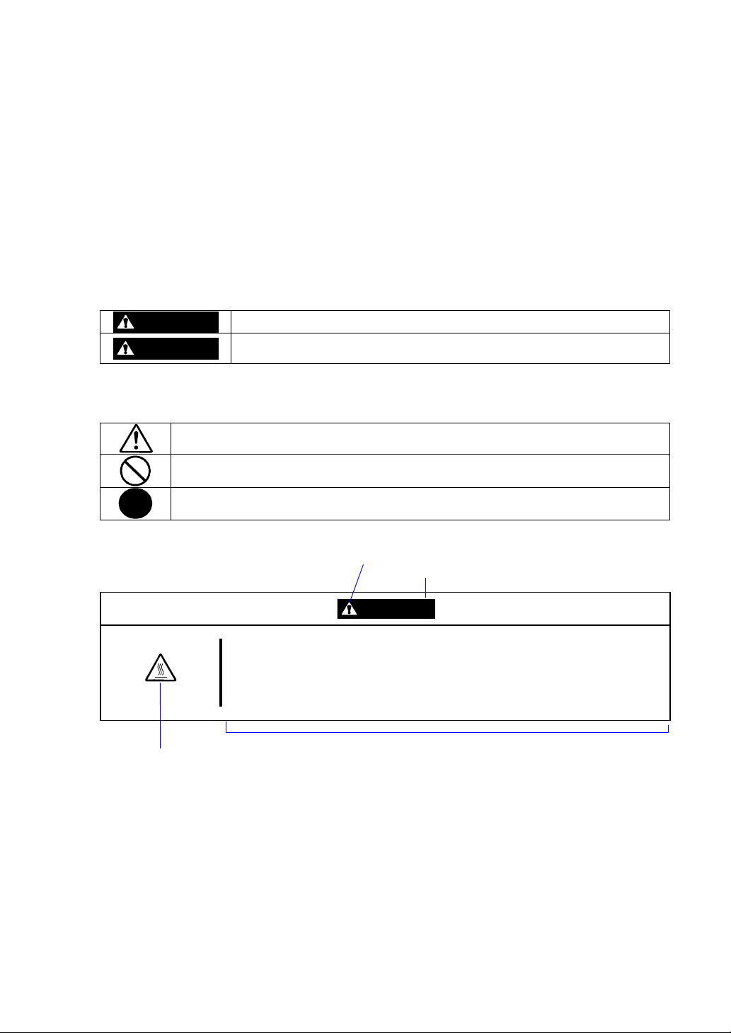
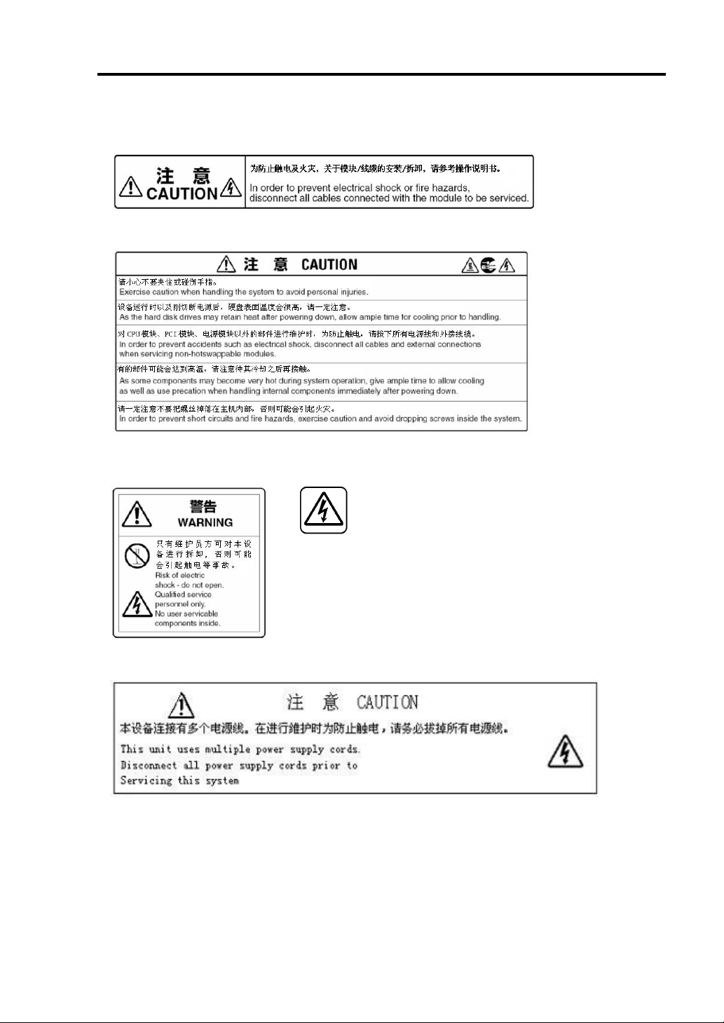
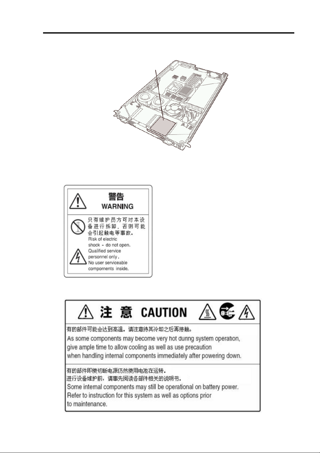
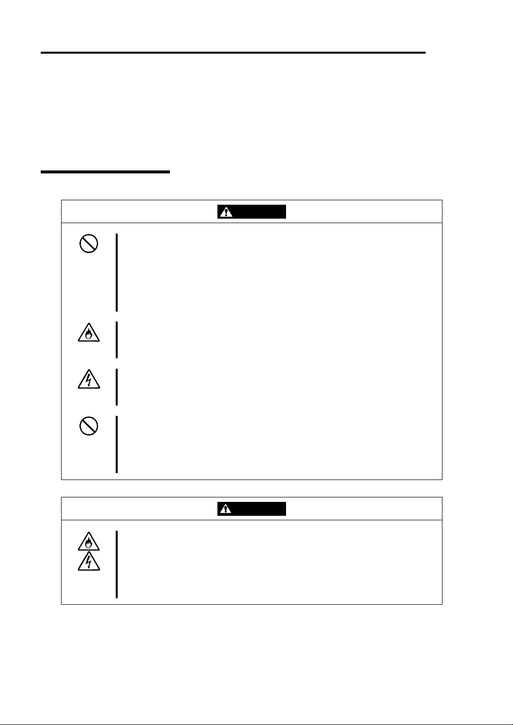
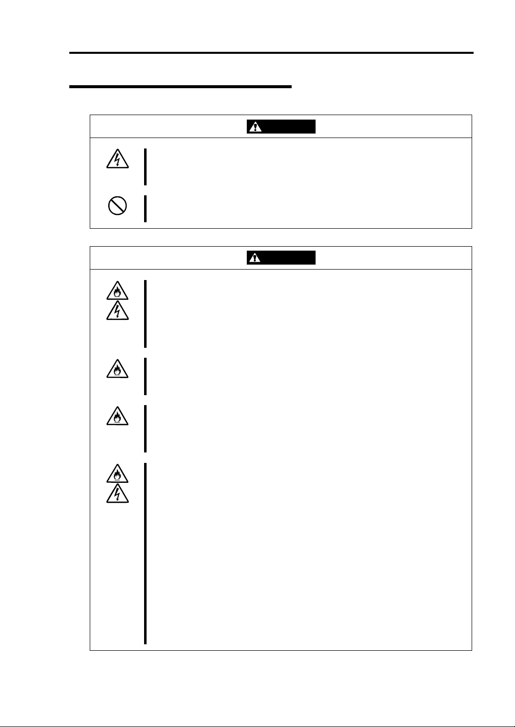
Warning Labels
Warning labels are placed in certain parts of the system so that the user stays alert to possible risks
(Do not remove or damage these labels).
If some label is missing, about to peel off, or illegible, contact your sales agent.
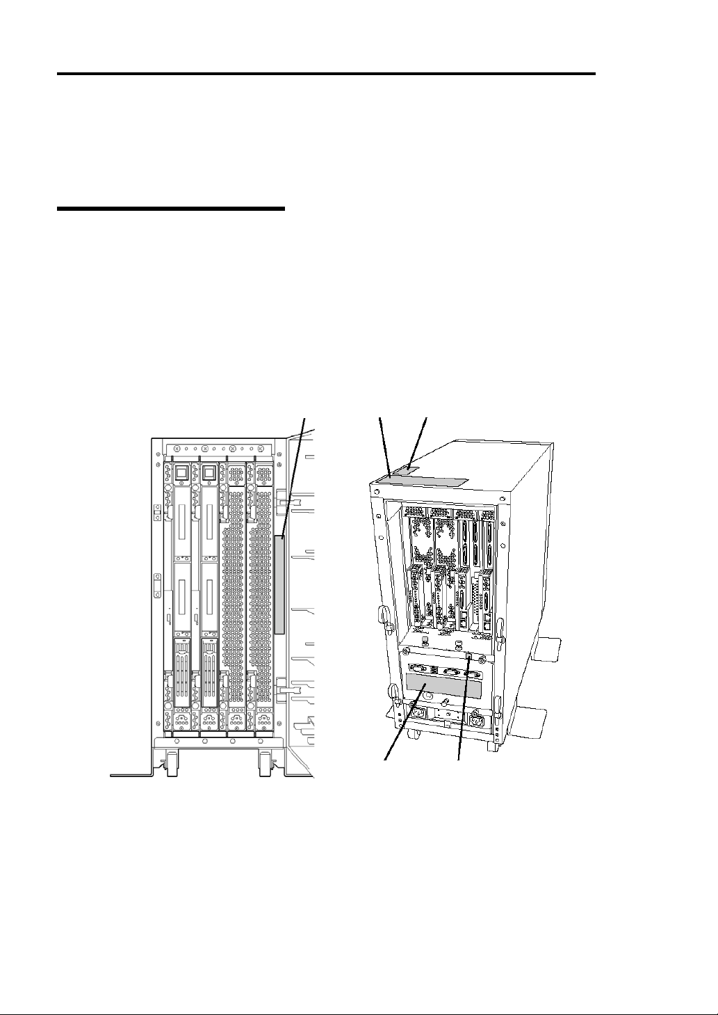
The figures below show locations of the labels on tower model and rack-mount model servers.
Tower Model
Label A
Label B
Label E Label D
Label C
Page 15
Before Setup 1-3
Label A
Label B
Label C
Label E
Label D
Page 16
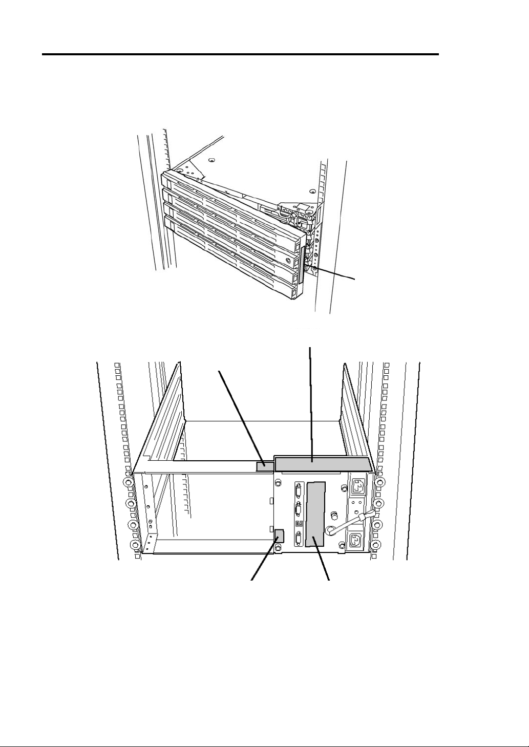
1-4 Before Setup
Rack-mount Model
Label A
Label B
Label C
Label E Label D
Page 17
Label A
Label B
Label E
Before Setup 1-5
Label D Label C
Page 18
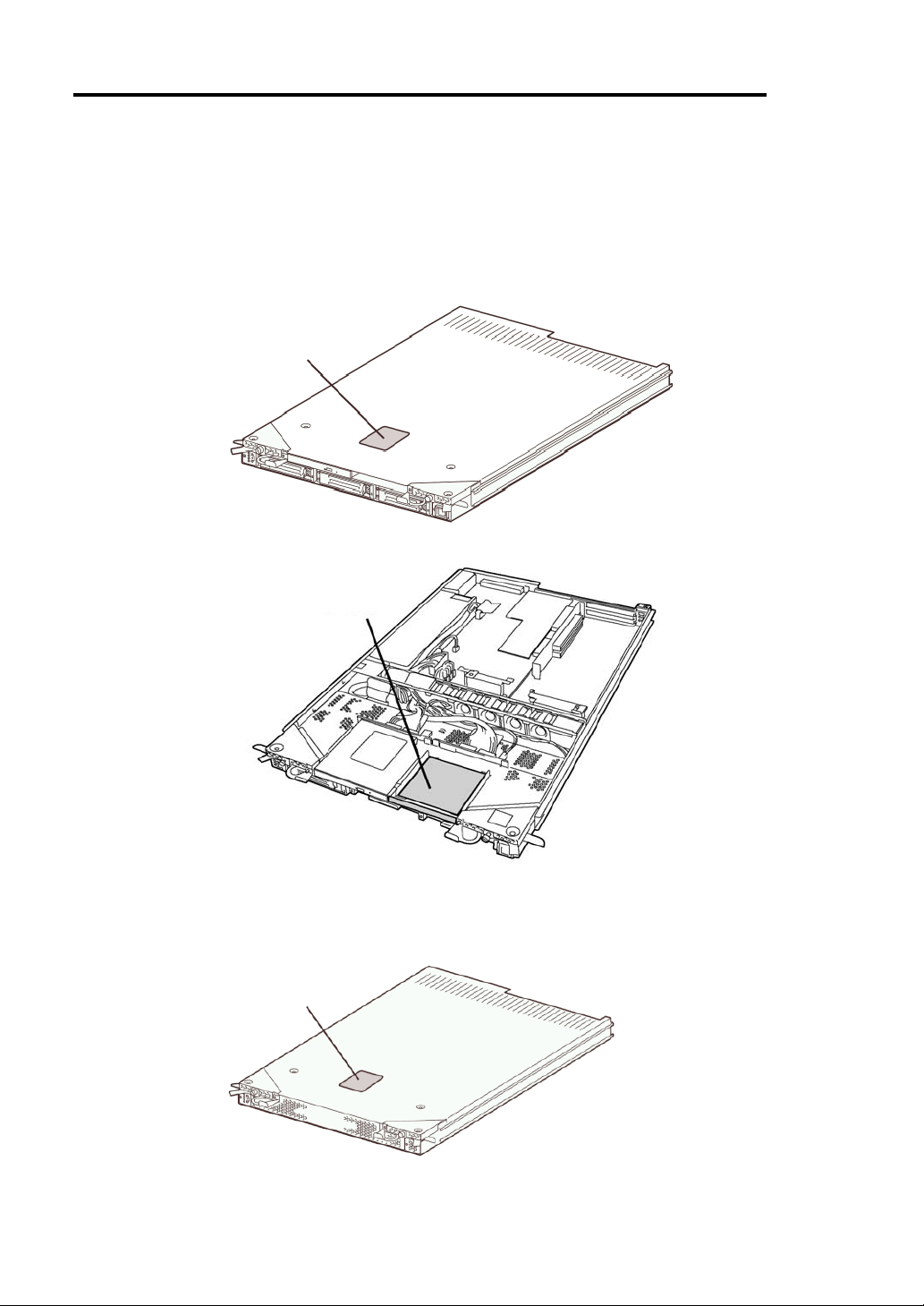
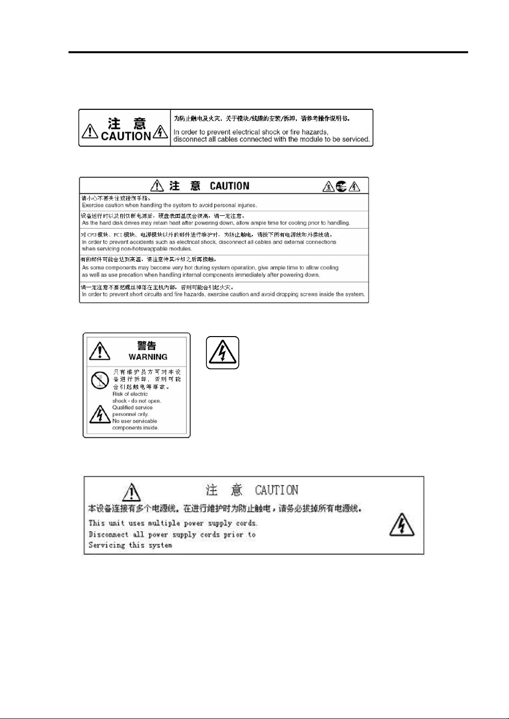
1-6 Before Setup
PCI/CPU Modules
PCI Module
Label A
CPU Module
Label B
Label A
Page 19
Before Setup 1-7
Label A
Label B
Label A
Label B
Page 20
1-8 Before Setup
Precautions for Safety
This section provides precautions for using the server safely. Read this section carefully to ensure
proper and safe use of the server. For symbol meanings, see "Safety Indications" described in the
previous section.
General
This equipment is not intended for use in controlling or use with facilities or
WARNING
Do not use the equipment in an operation where human lives are involved or
high reliability is required.
systems where human lives are involved or high reliability is required, inc luding
medical devices or nuclear, aerospace, transportation, and traffic control
facilities. NEC assumes no liability for any accidents or damage to physical
assets resulting from the use of this equipment in such systems or facilities.
Do not continue to use the equipment if you detect smoke, odor, or noise.
If the equipment emits smoke, odor, or noise, immediately flip off the POWER
switch, unplug the cord, and contact your sales agent. There is a risk of a fire.
Do not insert a wire or metal object.
Do not insert a wire or metal objects into a vent or disk drive slot. There is a risk
of an electric shock.
Do not use the equipment in an unsuitable place.
Do not install a server rack in an unsuitable environment.
Other systems also may be affected, and the rack may fall over to cause a fire
or injuries. For details about installation environment and quake-resistant
ngineering, see the attached manual or contact your sales agent. e
CAUTION
Prevent water or foreign objects from getting into the equipment.
Do not let water or foreign objects (e.g., pins or paper clips) enter the
equipment. There is a risk of a fire, electric shock, and breakdown. When such
things accidentally enter the equipment, immediately turn off the power and
unplug the cord. Contact your sales agent instead of trying to disassemble it
yourself.
Page 21
Use of Power Supply and Power Cord
Before Setup 1-9
WARNING
Do not handle a power plug with a wet hand.
Do not plug/unplug a power cord with a wet hand. There is a risk of an electric
shock.
Do not connect the ground wire to a gas pipe.
Never connect the ground wire to a gas pipe. There is a risk of a gas explosion.
CAUTION
Do not plug the cord in a nonconforming outlet.
Use a wall outlet with specified voltage and power type. There is a risk of a fire
or current leakage.
Avoid installing the equipment where you may need an extension c ord. If the
cord that does not meet the power specifications, there is a risk of overheating
that could lead to a fire.
Do not plug too many cords in a single outlet.
If the rated current is exceeded, there is a risk of overheating that could lead to
a fire.
Do not plug the cord insecurely.
Insert the plug firmly into an outlet. There is a risk of heat or fire due to poor
contact. If dust settles on the slots and it absorbs moisture, there is also a risk
of heat or fire.
Do not use nonconforming power cords.
Use the power cords specified by NEC. If the rated current is exceeded, there is
a risk of a fire.
You also have to observe the following prohibitions to prevent an electric shock
and a fire caused by damages of the cords.
Do not pull on the cord.
Do not pinch the cord.
Do not bend the cord.
Keep chemicals away from the cord.
Do not twist the cord.
Do not tread on the cord.
Do not place any object on the cord.
Do not use cords as bundled.
Do not alter, modify, or repair the cord.
Do not staple the cord.
Do not use any damaged cord. (Replace it with a new one of the same
specifications. For replacement procedures, contact your sales agent.)
Page 22
1-10 Before Setup
Installation, Relocation, Storage and Connection
WARNING
Disconnect the power cord(s) before installing or removing the equipment.
Be sure to power off the equipment and unplug its power cords from the wall
outlet before installation/relocation. All voltage is removed only when the power
cords are unplugged.
CAUTION
Do not hold the front bezel to lift the equipment.
The equipment weighs approximately 70 kg (depending on i ts hardware
configuration). Do not hold the front bezel, or it may become detached, causing
an injury. For lifting and moving the equipment, remove the mounted modules
from the main unit and carry them separately. It takes at least two people to
carry it; hold the equipment firmly by its bottom.
Do not install or store the equipment in an unsuitable place.
Install or store the equipment in such a place as specified in this User's Guide.
Avoid the following, or there is a risk of a fire.
a dusty place
a humid place located near a boiler, etc
a place exposed to direct sunlight
an unstable place
Be careful not to hurt your fingers.
Exercise great care not to hurt your fingers on the rail when you
mount/dismount the equipment into/from the rack.
Page 23
Before Setup 1-11
Do not connect any interface cable with the power cord of the server plugged to
a power source.
Make sure to power off the server and unplug the power cord from a power
outlet before installing/removing any optional internal device or
connecting/disconnecting any interface cable to/from the server. If the server is
off-powered but its power cord is plugged to power source, touching an internal
device, cable, or connector may cause an electric shock or a fire resulted from
a short-circuit.
Do not use any non-designated interface cable.
Use only interface cables designated by NEC; identify which component or
connector to attach beforehand. If you use a wrong cable or make a wrong
connection, there is a risk of short-circuit that could lead to a fire.
You also have to observe the following prohibitions about handling and
connecting interface cables:
Do not use any damaged cable connector.
Do not step on the cable.
Do not place any object on the cable.
Do not use the equipment with loose cable connections.
Do not use or store this product in a corrosive environment.
Avoid the usage or storage of this product in an environment which may be
exposed to corrosive gases, such as those including but not limited to :
sulfur dioxide, hydrogen sulfide, nitrogen dioxide, chlorine, ammonia and/or
ozone.
Avoid installing this product in a dusty environment or one that may be exposed
to corrosive materials such as sodium chloride and/or sulfur.
Avoid installing this product in an environment which may have excessive metal
flakes or conductive particles in the air.
Such environments may cause corrosion or short circuits within this product,
resulting in not only damage to this product, but may even lead to be a fire
hazard.
If there are any concerns regarding the environment at the planned site of
installation or storage, please contact your sales agent.
CAUTION
Page 24

1-12 Before Setup
Cleaning and Handling of Internal Devices
WARNING
Do not disassemble, repair, or alter the server.
Unless described herein, never attempt to disassemble, repair, or alter the
equipment. There is a risk of an electric shock or fire as well as malfunction.
Do not look into the CD-ROM drive
The CD-ROM drive uses a laser beam. Do not look or insert a mirror inside
while the system is on. A laser beam is invisible; if your eyes get exposed to it,
there is a risk of losing eyesight.
Do not detach a lithium battery yourself.
This equipment has a lithium battery. Do not detach it yourself. If the battery is
exposed to fire or water, it could explode.
When the lithium battery is running down and the equipment doesn’t work
correctly, contact your sales agent instead of disassembling, replacing or
recharging it yourself.
Disconnect the power plug before cleaning the server.
Make sure to power off the server and disconnect the power plug from a power
outlet before cleaning or installing/removing internal optional devices. Touching
any internal device of the server with its power cord connected to power source
may cause an electric shock even if the server is off-powered.
Disconnect the power plug from the outlet occasionally and clean the plug with
a dry cloth. Heat will be generated if condensation is formed on a dusty plug,
which may cause a fire.
High temperature
Immediately after powering off the system, system components such as hard
disk may be very hot. Wait for the server to cool down completely before
adding/removing components.
Make sure to complete installation.
Firmly install all power cords, interface cables and/or boards. An incompletely
nstalled component may cause a contact failure, resulting in fire and/or smoke. i
CAUTION
Page 25

During Operation
Before Setup 1-13
CAUTION
Do not pull out a device during operation.
Do not pull out or remove a device while it works. There is a risk of malfunction
and injuries.
Do not touch the equipment when it thunders.
Unplug the equipment when it threatens to thunder. If it starts to thunder before
you unplug the equipment, do not touch the equipment or cables. There is a
risk of a fire or electric shock.
Keep animals away.
Animal’s waste or hair may get inside the equipment to cause a fire or electric
shock.
Do not place any object on top of the server.
The object may fall off to cause injuries, damage to hardware and/or a fire.
Do not leave the CD tray ejected.
Dust may get in the equipment to cause malfunction. The ejected tray may also
become a cause of injuries.
Do not use a cellular phone or pager around the equipment.
Turn off your cellular phone or pager when you use the equipment. Their radio
waves may cause the equipment to malfunction.
Page 26
1-14 Before Setup
Rack-mount Model
CAUTION
Do not install the equipment on a nonconforming rack.
Install the equipment on a 19-inch rack confirming to the EIA standard. Do not
use the equipment without a rack or install it on a nonconforming rack. The
equipment may not function properly, and there is a risk of damage to physical
assets or injuries. For suitable racks, contact your sales agent.
Do not attempt to install the server yourself.
To avoid a risk of injuries, users should not attempt to install the equipment into
a rack. Installation should be performed by trained maintenance personnel.
< For Maintenance Personnel Only >
Do not remove and carry the equipment with modules mounted.
When you remove this product from the rack and carry it, remove all modules
that are mounted first.
Do not install the equipment in such a manner that its weight is imposed on a
single place.
To distribute the weight, attach stabilizers or install two or more racks. It may
fall down to cause injuries.
Do not assemble parts alone.
It takes at least two people to mount doors and trays to a rack. You may drop
some parts to cause a breakage or injuries.
Do not pull a device out of the rack if it is unstable.
Before pulling out a device, make sure that the rack is fixed (by stabilizers or
quake-resistant engineering).
Do not leave two or more devices pulled out from the rack.
If you pull out two or more devices the rack may fall down. You can only pull out
one device at a time.
Do not install excessive wiring.
To prevent burns, fires, and damage to the equipment, make sure that the rated
load of the power branch circuit is not exceeded. For more information on
installation and wiring of power-related facilities, contact your electrician or local
power company.
Page 27

Before Setup 1-15
Unpackaging
The following section describes necessary information to use the product properly and safely.
Accessories
This product is shipped with various accessories. See the attached list to make sure everything is
included and check the individual items. If any component is missing or damaged, contact your
sales agent.
Keep the accessories in a safe place. You will need them when you perform setup,
addition of options, or replacement of failed components.
To check Backup CD-ROM components, see the attached list.
Be sure to fill out and mail the software registration card that is shipped with the operating
system.
Make backup copies of included floppy disks, if any. Keep the original disks as the master
disks; use these copies in operation.
Improper use of an included floppy disk or CD-ROM may alter your system environment.
If you find something unclear, stop using them and contact your sales agent.
Main unit
Confirm the following after you unpack the product.
If your product has standard configurations, before you set up the main unit, attach
optional memory and CPU that you purchased separately. See the separate volume of
User’s Guide for details.
Page 28

1-16 Before Setup
This page is intentionally left blank.
Page 29

Chapter 2
About Operating System
This chapter gives essential information on the Linux system supported by the server and how to
install it.
Page 30

2-2 About Operating System
Installing Linux for NEC Express5800/ft series
For installing an operating system on NEC Express5800/ft series, use Backup CD-ROM.
IMPORTANT: The NEC Express5800/ft series is a precision instrument. You should ask
maintenance personnel to install it.
Before performing the ft series setup, contact your sales agent about the latest release of ft control
software.
About OS installation
Read the notes here carefully before installing the operating system.
Operating System Supported by the NEC Express5800/ft series
NEC Express5800/ft series supports the operating system, Linux for NEC Express5800/ft series.
NEC Express5800/ft series does not support any operating systems other than the above.
About Linux for NEC Express5800/ft series
Use the ft series setup program to install Linux for NEC Express5800/ft series. Note the following at
installation:
IMPORTANT:
Complete all the setups such as the memory expansion and the BIOS setting before
installing Linux for NEC Express5800/ft series.
NEC software package, which is to be purchased separately, is also provided with the
documentation for installation. However, see this User's Guide for installation into this
server.
After completing the ft series setup program, make settings for failure management (e.g.,
memory dump (debug information) setting) according to Chapter 4.
Page 31

Chapter 3
Installing Server
This chapter describes requirements for using the product properly and safely, the setup procedures
to make NEC Express5800/ft series ready for use, and ho w t o con nect peripherals.
Page 32
3-2 Installing Server
r
t
A
A
Installation
This section describes installation of NEC Express5800/ft series.
Tower Model
IMPORTANT: NEC Express5800/ft series is a precision instrument. You should ask
maintenance personnel to install it.
Select a suitable site for tower model.
CAUTION
Observe the following precautions to use the equipment safely. There are risks
of a burn, injury, or damage to physical assets. For details, see “Notes for Safe
Handling” in Chapter 1.
Remove all modules before moving the equipment.
Do not install the equipment in non-designated places.
Room that can maintain the following conditions:
Close enough to connect the
mouse and the display.
[When operating]
Temperature: 10 to 35ºC*
Humidity: 20 to 80%
Temperature gradient: ±10ºC/hr
tmospheric pressure: 749 to 1040hpa
[When not operating]
Temperature: 5 to 40ºC*
Humidity: 10 to 80%
Temperature gradient: ±15ºC/hr
tmospheric pressure: 749 to 1040hpa
100V - 120 V or 200V - 240
V parallel bi-polar power
outlet with grounding
Floor or a level
and robust desk or
table
Wall outlet within the
reach of supplied power
cord.
Location with an open space of 1m or more
on the front side, 50 cm or more on the rea
side, and 15cm or more on the right and lef
sides of the server. (The front bezel extrudes
about 50 mm from the right side of the
server when fully opened.)
Clean and tidy room
UPS to prevent momentary voltage drop due to power
failure or lightning *
* Optional. UPS is recommended for best use of
features of the “fault-tolerant” server.
* It is recommendable to use the server in a room where
temperature can be kept between 15 and 25ºC.
Page 33

Installing Server 3-3
Do not install NEC Express5800/ft series in such places as listed below. Otherwise, the server may
malfunction.
Place where temperatures change widely (near a heater, air conditioner, or refrigerator).
Place that is subject to intense vibration.
Place where corrosive gas (sodium chloride, sulfur dioxide, hydrogen sulfide, nitrogen
dioxide, or ozone)
is generated, or a place that is close to chemicals or exposed to
chemicals.
Place whose floor is covered with non-antistatic carpet.
Place that may be subject to falling objects.
Place where you may step or trip on the power cords or interface cables.
Place that is close to some equipment that generates intense magnetic field (e.g., TV set,
radio, broadcasting/communications antenna, power transmission wire, and
electromagnetic crane). (If unavoidable, contact your sales agent to request proper shield
construction.)
Place where the power cord of the server must be connected to an AC outlet that shares
the outlet of another device with large power consumption.
Place that is close to some equipment that causes power noises (e.g., sparks caused by
power-on/off using a relay). If you must install the server close to such equipment, request
your sales agent for separate power cabling or noise filter installation.
It takes at least two people to carry the server; hold it firmly by its bottom and place it slowly on the
selected site.
IMPORTANT: Do not hold the front bezel to lift it, or it may become detached and fall
down.
After placing the main cabinet, lock its two front casters and screw the attached four stabilizers on
the cabinet adjusting their height.
Screws
Stabilizer
Lock lever
Page 34

3-4 Installing Server
After fastening the main cabinet, open its front bezel to mount the CPU and PCI modules. For
details, see the following section “Installation of Rack-mount Model.” Procedures are basically the
same for the tower model except that its modules are mounted vertically instead of horizontally.
IMPORTANT: Follow the procedures below to install the CPU and PCI modules. Note
the following before installing them.
En sure the main cabinet is immobilized.
Place removed modules to the side of the main cabinet. Do not place modules on top of
the main cabinet.
Be sure to hold the modules tightly, and then mount them slowly and carefully.
If you cannot install modules smoothly, remove them and try again.
Install the CPU modules in the right two slots, the PCI modules in the left two slots.
Perform installation from the left slots.
Page 35

Installing Server 3-5
A
A
Installation of Rack-mount Model
You can mount NEC Express5800/ft series on a rack that conforms to the EIA standards.
IMPORTANT: NEC Express5800/ft series is a precision instrument. You should ask
maintenance personnel to install it.
To install a rack, contact your sales agent or maintenance personnel.
CAUTION
Do not attempt to install the server.
To avoid the risk of personal injury, users should not attempt to install the
server into the rack assembly. The server should be installed in the rack only by
trained maintenance personnel.
Room that can maintain the following
conditions:
[When operating]
Temperature: 10 to 35ºC*
Humidity: 20 to 80%
Temperature gradient: ±10ºC/hr
tmospheric pressure: 749 to 1040hpa
[When not operating]
Temperature: 5 to 40ºC*
Humidity: 10 to 80%
Temperature gradient: ±15ºC/hr
tmospheric pressure: 749 to 1040hpa
100V - 120 V or 200V - 240 V
parallel bi-polar power outlet
with grounding
Wall outlet within the
reach of supplied power
cord.
Space 40 cm or more on top, 1 m or more
on the front and rear, and 60 cm or more on
the right and left.
Level and reinforced
floor.
* It is recommended to use the server in a room where
temperature can be kept between 15 and 25ºC.
Page 36

3-6 Installing Server
Observe the following precautions to use the server safely. There are risks of a
death or serious injury. For details, see “Notes for Safe Handling” in Chapter 1.
Do not install the equipment in non-designated places.
Do not connect the ground wire to a gas pipe.
WARNING
Observe the following precautions to use the equipment safely. There are risks
of a burn, personal injury, or damage to physical assets. For details, see “Notes
for Safe Handling” in Chapter 1.
Do not carry or install the equipment alone.
Do not install the equipment in such a manner that its weight is imposed on
a single place.
Do not assemble or disassemble parts alone.
Do not pull a device out of the rack if it is unstable.
Do not leave two or more devices pulled out from the rack.
Do not install excessive wiring.
CAUTION
Do not install NEC Express5800/ft series in such places as listed below. Otherwise, the server may
malfunction.
Place where you cannot pull out the components fully.
Place that cannot sustain the total weight of the rack system.
Place where you cannot mount stabilizers or where you cannot perform installation
without quake-resistant engi n eeri n g.
Place whose floor is uneven or inclined.
Place where temperatures change widely (near a heater, air conditioner, or refrigerator).
Place that is subject to intense vibration.
Place where corrosive gas (sodium chloride, sulfur dioxide, hydrogen sulfide, nitrogen
dioxide, or ozone)
is generated, or a place that is close to chemicals or exposed to
chemicals.
Place whose floor is covered with non-antistatic carpet.
Place that may be subject to falling objects.
Place that is close to some equipment that generates intense magnetic field (e.g., TV set,
radio, broadcasting/communications antenna, power transmission wire, and
electromagnetic crane). (If unavoidable, contact your sales agent to request proper shield
construction.)
Place where the power cord of the server must be connected to an AC outlet that shares
the outlet of another device with large power consumption.
Page 37

Installing Server 3-7
Place that is close to some equipment that causes power noises (e.g., sparks caused by
power-on/off using a relay). If you must install the server close to such equipment, request
your sales agent for separate power cabling or noise filter installation.
IMPORTANT: Temperature increase inside the rack and airflow
If you install several components or the ventilation isn’t good inside the rack, the internal
temperature may increase due to heat emitted from the components. When the operating
temperatures of NEC Express5800/ft series (10 to 35°C) are exceeded, there is a risk of
malfunction. You must take adequate precautions and measures for airflow inside the rack as
well as in the room so that the internal temperature can be kept within this range during
operation.
Page 38

3-8 Installing Server
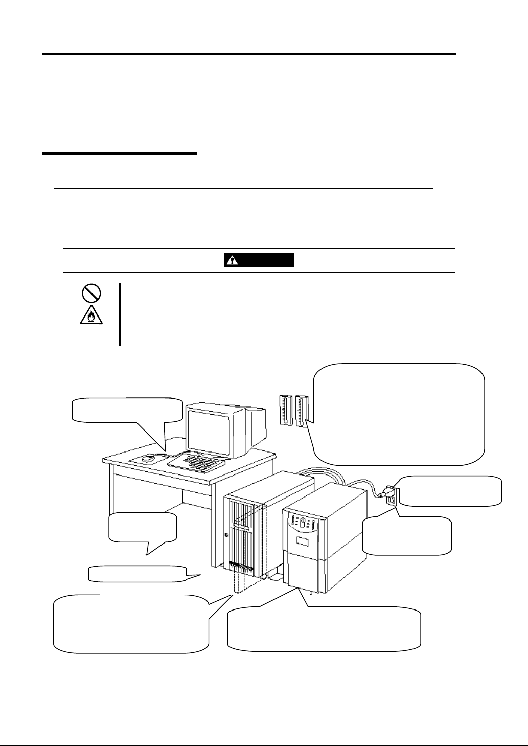
Connection
Connect peripheral devices to NEC Express5800/ft series.
The server is provided with connectors for wide variety of peripheral devices on its front and rear.
The figure on the next page illustrates available peripheral devices for the server in the standard
configuration, and locations of the connectors for the devices. After connecting the peripheral
devices, connect the provided power cords with the server, then plug the power cords into the power
outlet.
Observe the following precautions to use the server safely. There are risks of a
death or serious injury. For details, see “Notes for Safe Handling” in Chapter 1.
Do not hold the power plug with a wet hand.
Do not connect the ground wire to a gas pipe.
WARNING
Observe the following precautions instructions to use the equipment safely.
There are risks of a burn, personal injury, or damage to physical assets. For
details, see “Notes for Safe Handling” in Chapter 1.
Do not plug the power cord in a nonconforming outlet.
Do not plug too many cords in a single outlet.
Do not plug the cord insecurely.
Do not use nonconforming power cords.
CAUTION
IMPORTANT:
Power off the server before connecting peripheral devices, with the exception of
peripherals with USB interface. Connecting a powered peripheral device to the powered
server will cause malfunctions and failures.
To connect a third-party peripheral device or interface cable to the server, check with
your sales agent to see if they are compatible with NEC Express5800/ft series. Some
third-party devices may not be used with the server.
The total cable length of SCSI device connections is up to 6 m, including the internal
SCSI cables.
The serial port connectors are reserved for maintenance.
Page 39

Installing Server 3-9
r
A rack-mount model is shown here. As for a tower model, locations of the connectors are same
though the orientation of the equipment is different.
IMPORTANT: Space of 1U above the main unit is needed to place the USB floppy disk
drive on the main unit for a rack-mount modelFor a tower modelplace it on the main unit.
USB floppy
disk drive
Reserved fo
maintenance
Reserved for
maintenance
Keyboard (via keyboard hub to mouse)
Display
To a SCSI
backup device
To a 1000Mbps
network
To a 100Mbps
network
IMPORTANT: Connection of optional devices
In the case of standard configuration, you need to complete setup of the operating system
before mounting optional PCI cards or hard disks that you purchased separately.
Page 40

3-10 Installing Server
A
A
After connecting cables to PCI modules, secure them with the cable ties.
When completing connection to peripheral equipment, connect the two provided power cords to the
server. After that, secure the cables with the cable tie prov ided in the server.
Connect the plug at the other end of the power cord to a wall outlet with parallel double-pole
grounds provided or to an uninterruptible power supply (UPS).
To use the functions of the server, you should connect the server to the UPS.
C inlet B
(for Group 1)
Power cords
C inlet A
(for Group 2)
<Example>
Cable tie
IMPORTANT:
Be sure to use both of the power cords to use fault tolerant functions.
If both PCI modules are mounted, the one you plug in first will become the primary module.
The AC inlet B is used for Group 1; the AC inlet A is for Group 2.
The module whose POWER switch LED is on is the primary.
Page 41

Installing Server 3-11
To connect the power cords from the server to an uninterruptible power supply (UPS), use service
outlets on the rear of the UPS.
The UPS service outlets are categorized into two groups: SWITCH OUT and UN-SWITCH OUT.
(They may be called "OUTPUT1" and "OUTPUT2".)
For constant power supply, connect the power cord to a UN-SWITCH OUT outlet. (Connect the
modem that is in service for 24 hours to this outlet.)
When the power cords from the server are connected to a UPS, change the BIOS setup of the server
to link with power supply from the UPS.
Select [AC-LINK] from [System Hardware] on the BIOS setup utility and change parameters. See
the separate volume of User’s Guide for details.
<Example>
Page 42

3-12 Installing Server
This page is intentionally left blank.
Page 43

Chapter 4
Linux Setup
This chapter describes procedures for setup to power on the NEC Express5800/ft series for the first
time, installation of Linux, setup of dual configuration of LAN cards, setup of dual disk configurat ion
and so on.
Page 44

4-2 Linux Setup
N
Setup Flow
The following flow-chart illustrates the flow of the setup procedures for the server.
When powering on
the server the first time
Y
Do you power on the ft series
for the first time?
When reinstalling
the OS.
Step A-1: Starting Setup Procedure When
Powering on the Server for the First
Time (P.4-3)
Step B-1: Starting Setup Procedure When
Reinstalling the OS (P.4-5)
Step B-2: Prepare for Installation (P.4-6)
Step B-3: Start the Installation of Linux for NEC
Express5800/ft series (P.4-9)
Step C-1: Set Dual LAN Card Configuration (P.4-10)
Step C-2: Set Dual Disk Configuration (P.4-13)
Step C-3: Connect and Configure Options (P.4-19)
Step C-4: Create Volume (P.4-19)
Step C-5: Set Network for NEC ESMPRO Agent (P.4-19)
Step C-6: Back up System Information (P.4-20)
Setup completed
Page 45

Linux Setup 4-3
Setup Procedure When Powering on the NEC
Express5800/ft series for the First Time
Follow the procedure below to set up the server for the first time after you purchased.
Step A-1: Starting Setup Procedure When Powering on the Server for
the First Time
The following explains the initial setup procedure of the NEC Express5800/ft series after you
purchased.
You need to prepare the following before starting setup.
User’s Guide (Setup) (this manual)
User’s Guide
CHECK: You don’t need to use any media (e.g., CD-ROM).
IMPORTANT:
You cannot set up the NEC Express5800/ft series properly using procedures other
than the one described on this manual.
The CPU module Status LED 1 and the PCI module Status LED 1 illuminate red
during setup. It does not indicate a malfunction of the module. When the setup has
completed and each module is duplicated properly, the CPU module Status LED 1 and
the PCI module Status LED 1 go out and the CPU module Status LED 2 and the PCI
module Status LED 2 illuminate green. Fo r details of t he indications of m odule’s Status
LEDs, see “LEDs” on the separate volume of User’s Guide.
The preinstalled OS requires setting of dual LAN card configuration. Make sure to
perform the setting on step 5.
1. Power on the server after the hardware setup has completed.
The preinstalled Linux for NEC Express5800/ft series will start.
2. Enter a login name.
When the startup is completed, the login prompt, “localhost login:” will be displayed.
Enter “root”, and then press Enter.
3. Enter the password.
“Password:” will be displayed. Enter the password provided on the “Password of 'root'
user” packaged with the backup CD-ROM, and then press Enter. The password is
case-sensitive.
If the message “Login incorrect” appears and the system waits for the user t o enter the
password again, the login name or the password was incorrect. Enter the login name
and the password again.
Page 46

4-4 Linux Setup
4. Change the root password.
Change the password using passwd comma nd.
5. Set LAN configuration.
See “Step C-1: Set Dual LAN Card Configuration” (4-9) and perform the setup.
6. Connect and setup the optional devices.
If there are optional PCI boards and peripheral devices which have been purchased
separately, power off the server and then follow the instructions of “PCI board” in the
separate volume of User’s Gui de and the manuals of de vices. If you added a LAN ca rd
or a disk to the server, you need to set dual configuration. For details, see “Step C-1:
Set Dual LAN Card Configuration” (4-9) and “Step C-2: Set Dual Disk
Configuration” (4-13).
Setup is now completed.
To perform the setup again, see “Setup Procedure When Reinstalling the OS” (4-5).
Page 47

Linux Setup 4-5
Setup Procedure When Reinstalling the OS
You can set up the NEC Express5800/ft series again using a backup CD-ROM.
IMPORTANT:
The NEC Express5800/ft series is a precision instrument. Ask maintenance personnel
with technical knowledge to install it.
Whe n you power on t he NEC Express5800/ft series for the first tim e after you purchased,
refer to “Setup Procedure When Powering on the NEC Exp ress5800/ft series for the First
Time” (4-3) to set up.
The following is the procedure to reinstall the OS.
Step B-1: Starting Setup Procedure When Reinstalling the OS
The following explains the reinstallation procedure of the OS.
You need the following to install Linux for NEC Express5800/ft series.
Linux for NEC Express5800/ft series Back Up CD-ROM 1
Linux for NEC Express5800/ft series Back Up CD-ROM 2
“Password of 'root' user” leaflet
User’s Guide (Setup) (this manual)
User’s Guide
IMPORTANT: For the latest release of Linux for NEC Express5800/ft series software,
ask your sales agent.
Page 48

4-6 Linux Setup
(
)
Step B-2: Prepare for Installation
Before starting Linux for NEC Express5800/ft seri es installation, be sure to do the following. If these
preparations are not performed, setup cannot be performed properly.
Prepare NEC Express5800/ft series
With the power of NEC Express5800/ft series off, follow the steps below:
1. Prepare NEC Express5800/ft series.
Perform the following preparations.
• Remove all optional PCI boards and peripheral devices.
• Mount the PCI modules (for Group1/for Group2), and CPU modules (for Group1/for
Group2).
• Insert one hard disk to the Slot1 of each PCI module (for Group1/Group2).
• Remove all LAN cables.
2. Make the PCI module for Group1 primary.
The location of the parts required for operation and confirmation are shown below.
BMC Status LED
PCI module Status LED1
PCI module
Status LED2
PCI module
(for Group2)
PCI module
for Group1
CPU modules
CD-ROM drives
Rack-mount model (Front)
POWER switch
Page 49

Linux Setup 4-7
A
A
C inlet B (for Group1)
C inlet A (for Group2)
Rack-mount model (Rear)
<When the AC power is off (The power cords are not plugged into the outlet)>
Connect the power cords to NEC Express5800/ft series in the following order:
(1) Connect the power cord to the AC inlet B (for Group1)
(2) Connect the power cord to the AC inlet A (for Group2)
(3) Confirm that the POWER switch of the PCI module for Group1 is illuminated.
(4) Make sure that the two BMC Status LEDs for PCI modules (for Group1/for Group2) are
turned off.
IMPORTANT: If the BMC Status LED is red and blinking, do not start installing
Linux for NEC Express5800/ft series. Otherwise the setup may not be performed
properly.
Preparation is now completed. Start the installation of Linux for NEC Express5800/ft series.
<When the AC power is on (The power cord is plugged to the wall outlet and the main unit’s
power is off)>
(1) Check the LED of the PCI module’s POWER switch.
• If the PCI module for Group1’s POWER switch is lit, the PCI module for Group1 is
primary. Preparations are complete. Start the installation of Linux for NEC
Express5800/ft series.
• If the PCI module for Group2’s POWER switch is lit, the PCI module for Group1 is
secondary. Continue to (2). Make PCI module for Group1 the primary module.
Page 50

4-8 Linux Setup
(2) Make sure that the two BMC Status LEDs of the PCI modules (for Group1/for Group2) are
turned off.
IMPORTANT: While the BMC Status LED is red and blinking, do not
perform (3) and on. Otherwise the BMC firmware may become damaged.
(3) Remove the power cord of the AC inlet A (for Group2).
(4) Check that the POWER switch of the PCI module for Group1 is turned on.
(5) Connect the power cord of the AC inlet A (for Group2).
(6) Make sure that two BMC Status LED for PCI modules (for Gr oup 1/f or Gr oup 2) a re turn ed
off.
IMPORTANT: If the BMC Status LED is red and blinking, do not start
installing Linux for NEC Express5800/ft series. Otherwise the setup may not be
done properly.
Preparation is now completed. Start the installation of Linux for NEC Express5800/ft series.
Page 51

Linux Setup 4-9
Step B-3: Start the Installation of Linux for NEC Express5800/ft series
Follow the steps below to install Linux for NEC Express5800/ft series.
IMPORTANT:
The CPU module Status LED 1 and the PCI module Status LED 1 illuminate red during
setup. It does not indicate a malfunction of t he m odule. When the set up has com plet ed and
each module is duplicated properly, the CPU module Status LED 1 and the PCI module
Status LED 1 go out an d t he CPU module Status LED 2 an d the PC I m odul e Status LED 2
illuminate green. For details of the indication of module’s Status LEDs, see “LEDs” on the
separate volume of User’s Guide.
1. Turn on the NEC Express5800/ft series.
2. Insert the “Linux for NEC Express5800/ft series Back Up CD-ROM 1” CD-ROM into the
CD-ROM drive of the NEC Express5800/ft series.
IMPORTANT: For the installation of Linux for NEC Express5800/ft series, insert the
CD-ROM into the PCI module for Group1’s CD-ROM drive.
3. When having inserted the CD-ROM correctly, reset the system (press Ctrl, Alt and Delete
together), or turn the power off and then turn it on to restart the NEC Express5800/ft series.
The installation will be started. After a while, the message “Change CDROM” will appear.
4. Follow the message and change the CD-ROM to the Back Up CD-ROM 2.
5. Press Enter.
When the installation has completed properly after a while, a message “Complete” will appear.
6. Press Enter.
The system will restart automatically and the Back Up CD-ROM 2 will be ejected. Take out
the CD-ROM.
The root password after the restart is the one which was set to the server when you purchased i t.
For the preset password, see “Password of 'root' user” packaged with the backup CD-ROMs.
For security, change the password after logging in as a root user.
IMPORTANT:
After the system restarted, the status of the two disks installed for constructing RAID
become “RESYNCING” or “RECOVER Y” for a while. Do not stop or restart the system
while the status of “RESYNCING” or “RECOVERY” continues. You can check the
status of RAID by using ftdiskadm.
The installation of Linux for NEC Express5800/ft series is now completed.
Step C-1: Set Dual LAN Card Configuration
LAN configuration is not set to Linux for NEC Express5800/ft series preinstalled to the hard disk
Page 52

4-10 Linux Setup
drive of the NEC Express5800/ft series, or after Linux for NEC Express5800/ft series is reinstalled. If
you use a network, you need to set dual LAN card configuration.
The NEC Express5800/ft series builds a dual LAN card configuration by using “Stratus emb-82559
10/100 Enet Adapter” (100Base) and “Stratus emb-82544GC Copper Gigabit Adapter” (1000Base)
mounted as standard on the PCI module.
The following is a description of setting 100Base built-in LAN card.
For the setting of 1000Base built-in LAN card, perform the following by changing “7” used for slots
and commands on the description to “4”.
TIPS: To set dual LAN card configuration, you need to log in as a root user.
1. Log in to the system as a root user.
2. Execute the following command to check if the indication of LAN card a ppears on the slot 7.
>vndctl status
-Virtual Network Statusvirtual status ipconf slot real(s)
slot real status link
1 left -
right -
2 left -
right -
3 left -
right -
4 left gb01.03.0 -
right gb40.03.0 -
5 left -
right -
6 left -
right -
7 left epro01.06
right epro40.06
3. Execute the following command to add the LAN card of the slot 7 to the VND list.
>vndctl add 7
Page 53

4. Use the following command to check the status of LAN card.
>vndctl status 7
You can check the status of the slot 7 using vndctl.
--Virtual Network Status--
virtual status ipconf slot real(s)
ha0 OKAY no 7 *epro01.06 epro40.06
Link encap:Ethernet HWaddr 00:30:13:F1:E9:7D
BROADCAST MASTER M ULTICAST MTU:1500 Metric:1
RX packets:0 errors:0 dropped:0 ove rruns:0 frame:0
TX packets:0 errors:0 dropped:0 ove rruns:0 carrier:0
collisions:0 txqueuelen:0
RX bytes:0 (0.0 b) TX bytes:0 (0.0 b)
slot real status link
7 left epro01.06 DOWN
Link encap:Ethernet HWaddr 00:30:13:F1:E9:7D
BROADCAST SLAVE MTU:1500 Metric:1
RX packets:12242 errors:0 droppe d:0 overruns:0 frame:0
TX packets:129 errors:0 dropped: 0 overruns:0 carrier:0
collisions:0 txqueuelen:100
RX bytes:946021 (923.8 Kb) T X bytes:6876 (6.7 Kb)
Interrupt:47 Base address:0xb000
right epro40.06 DOWN
Link encap:Ethernet HWaddr 00:30:13:F1:E9:7D
BROADCAST SLAVE MTU:1500 Metric:1
RX packets:125 errors:0 dropped: 0 overruns:0 frame:0
TX packets:0 errors:0 dropped:0 ove rruns:0 carrier:0
collisions:0 txqueuelen:100
RX bytes:8928 (8.7 Kb) TX bytes:0 (0.0 b)
Interrupt:19 Base address:0xd000
Linux Setup 4-11
“ha0” indicates the interface name (ha0) which is used to set dual configuration to the two
LAN cards and then virtually treat them as one LAN card, and their setting values. The
descriptions under “ha0” are values set for two LAN cards.
5. Use the following comm and to m ake set tings of t he d ual LAN ca rd c onfi gu ratio n of the slot
7.
>vndctl config 7
The screen will be switched to the entry screen. (netconfig command is being executed.)
The message “Would you like to set up networking?” will appear. Click “Yes” to continue.
Specify whether you use DHCP or not, and IP addresses, etc., depending on the operating
environment.
6. Use the following command to activate the dual LAN card configuration of the slot 7.
>vndctl up 7
Page 54

4-12 Linux Setup
g
7. Check the status.
>vndctl status
-Virtual Network Statusvirtual status ipconf slot real(s)
ha0 OKAY yes 7 *epro01.06 epro40.06
slot real status link
1 left -
right -
2 left -
right -
3 left -
right -
4 left gb01.03.0 -
right gb40.03.0 -
5 left -
right -
6 left -
right -
7 left epro01.06 UP LINK
ri
ht epro40.06 UP LINK
Dual LAN card configuration has completed when the screen displays the status is “UP”,
and the link is “LINK” (with LAN cable connected) as shown above.
8. Execute the following command to check whether the settings such as IP addresses are set
correctly.
>vndctl ipconf 7
DEVICE=ha0
ONBOOT=yes
BOOTPRONTO=static
IPADDR=192.168.99.10
NETMASK=255.255.255.0
GATEWAY=192.168.99.1
Page 55

Linux Setup 4-13
Step C-2: Set Dual Disk Configuration
If you are performing “Setup Procedure When Powering on the NEC Express5800/ft series for the
First Time”, go to “Step C-3: Connect and Configure Options” (4-19).
At the time of shipment of the NEC Express5800/ft series, the following settings have been already
made so that you can use the server immediately after the purchase.
NEC Express5800/ft series secures data by making disks to RAID configuration.
NEC Express 5800/ft series is set up to automatically set dual configuration of the built-in disk for
boot in either status; when you purchased the server, or immediately after Linux for NEC
Express5800/ft series was installed t o the se rver. However, make sure to check the status of d ual di sk
configuration to prevent unexpected problems. If needed, set dual d isk configuration.
IMPORTANT: If you are performing “Setup Procedure When Powering on the NEC
Express5800/ft series for the First Time”, this step is not needed as the dual disk configuration
has already been configured. Go to “Step C-3: Connect and Configure Options” (4-19).
TIPS: To set dual disk configuration, you need to log in as a root user.
IMPORTANT:
Make sure to set RAID not only when i nstalling an ope rating syst em but al so when addi ng
disks or reconstructing RAID.
When adding disks or reconstructing RAID, the status of each disk becomes
“RESYNCING” or “RECOVERY”. Do not remove disks, turn off the power, or restart the
system during this status. Wait until the status “RESYNCING” or “RECOVERY” is
finished. You can check the status of RAID using ftdiskadm described later.
Page 56

4-14 Linux Setup
Disk management tool (ftdiskadm)
You can check the status of the integrated SCSI disk and set the RAID configuration safely by using
disk management tool (ftdiskadm).
By using ftdiskadm, you can;
Check the status of the entire built-in disks
Check the status of RAID of the built-in disks
Recover RAID of the built-in disk
Extend the built-in disk
Detach the built-in disk
<Example>
# ftdiskadm
Command action
1 => SCSI
2 => RAID
3 => Environment
9 Quit
Command: 2
Command action
1 Status(Raid)
2 Status(All Disks)
3 Repair Disk
4 New Disks
5 Remove Half Disk
6 Remove Full Disks
9 <= RETURN
Command:
...
Page 57

Linux Setup 4-15
Check the status of the SCSI disk
Check the status of the SCSI disk using ftdiskadm command.
The following is an example of the display when “Status(All Disks)” of “=> RAID” is executed.
<Example>
[SCSI DISK STATUS]
-- BUS -bus pci(haddr)
0 01:05.00(10.5.0)
1 40:05.00(11.5.0)
2 01:02.00(10.2.0)
3 40:02.00(11.2.0)
-- SYSTEM -slot name use serial tuple path
1 sda 7 #3JA73L5R00007430B065 b0t0l0 d10h0c0t0l0
2 3 4 sdd 7 #3JA73HYE000074298UHV b1t0l0 d11h1c0t0l0
5 6 -
-- EXTENSION - name use serial tuple path
sdh 0 #0000924310220000 b3t0l0 d0h3c0t0l0
b2t0l0 d0h2c0t0l0
sdi 0 #0000924310220001 b3t0l0 d0h3c0t0l1
b2t0l0 d0h2c0t0l1
“--BUS--” part is the information of a SCSI BUS.
“bus” indicates <SCSI_BUS_number>, “pci” indicates <PCI_BUS
number>:<PCI_SLOT_number>.<CHANNEL_number>, and “(haddr)” indicates
<hardware_address>.
“--SYSTEM--” part is the information of a standard integrated SCSI disk, and “--EXTENSION--”
part is a SCSI disk number connected to the Fibre Channel Controller extended on the PCI slot.
slot is <SCSI_disk_slot_number>, name is <device_name>, use is <current_usage_count>, serial is
#<serial_number>, tuple is <SCSI_tuple>, and path is <SCS_path>.
<SCSI_tuple>=b<BUS_number>t<TARGET_number>|<LUN>
<SCSI_path>=d<DOMAIN_number>h<HOST_number>c<CHANNEL_number>t<TARGET_num
ber>|<LUN>
The first tuple and path displayed are active.
CHECK: If you expand the Fibre Channel Controller to the PCI slot, configuration of the
topology is required.
Check the status of RAID of the disk on “Status(Raid)”.
1. Log in as a root user.
2. Execute the following command to start ftdiskadm.
>ftdiskadm
Page 58

4-16 Linux Setup
3. Enter “2” and then press Enter.
The RAID menu will be displayed.
4. Enter “1” and then press Enter.
“Status (Raid)” (the disks’ current status of RAID) will be displayed.
(Display example of the RAID status)
[Status(Raid)]
-----------------------------------------------------------------------------------------------
name partition label status member
md0 /boot /boot DUPLEX (1)sda1 (4)sdd1
md1 /user /usr DUPLEX (1)sda5 (4)sdd5
md2 /home /home DUPLEX (1)sda10 (4)sdd10
md3 /var /var DUPLEX (1)sda6 (4)sdd6
md4 / / DUPLEX (1)sda8 (4)sdd8
md5 /tmp /tmp DUPLEX (1)sda9 (4)sdd9
md6 swap DUPLEX (1)sda7 (4)sdd7
-----------------------------------------------------------------------------------------------
“name” is the name of a software RAID device.
“partition” is a mount point or a swap. If this field is blank, RAID is configured but not
mounted as a file system.
“member” is the information of the member configuring RAID. The information will be
displayed in the following format for the number of members.
(Slot number) name
If the status is error, (F ) is marked on the left. In such a case, you need to correct RAID. status
indicates the status of RAID. The following are the descriptions of the status messages.
DUPLEX : Normal status.
RESYNCING (X.X%) : Being synchronized. When completed, it becomes
DUPLEX.
RECOVERY (X.X%) : Being recovered. The members with “-” mark on the
member field have not been built yet.
SIMPLEX : Only one side of RAID is built. If two members are
displayed on the member field, the member with “-” mark is on
standby before RECOVERY status. If only one member is
displayed, recovery is required.
ERROR : ERROR status. The members of RAID do not exist.
Page 59

Start the SCSI disk
To start the SCSI disk manually, use ftdiskadm.
The following is an example of procedure to start SCSI disk using ftdiskadm.
<Example>
Command action
1 => SCSI
2 => RAID
3 => Environment
9 Quit
Command: 1
Command action
1 Status(All Disks)
2 Status(System Disks)
3 Status(Extended Disks)
4 Bring Up
5 Bring Down
9 <= RETURN
Command: 4
[Bring Up]
* Which disk(s)? [‘?’ for help] => (10.1)t0I* (Note 1)
ftdisk: ERROR(1): Bringing up reached timeout! (Note 2)
<<<Check the status of SCSI disk>>>
Linux Setup 4-17
Note 1: You can list the disk specification methods by entering “?”.
“*” can be used in the TARGET section and LUN section, and the range will be from 0 to the
sum of the maximum number succeeded to start and the number of overrun. The number of
overrun is the value of the environment variable FTDISKADM_TID_OVERRUN for
TARGET, and FTDISKADM_LUN_OVERRUN for LUN. It can be checked/modified on
“Environment” of each menu. In addition, you can put the numbers inside “[ ]” (e.g.,
[<num1>,<num2>]), or specify the range of the numbers (e.g., [<num3>,<num5>]).
Note 2: If the values of overrun are 1 or more, some may fail according to the value.
Check the status for the command execution number.
Page 60

4-18 Linux Setup
Stop the SCSI disk
To stop the SCSI disk manually, use ftdiskadm.
The following is an example of procedure to stop the SCSI disk using ftdiskadm.
<Example>
Command action
1 => SCSI
2 => RAID
3 => Environment
9 Quit
Command: 1
Command action
1 Status(All Disks)
2 Status(System Disks)
3 Status(Extended Disks)
4 Bring Up
5 Bring Down
9 <= RETURN
Command: 5
[Bring Down]
* Which disk(s)? [‘?’ for help] => (10.1)t0I5 (Note 1)
* Bringing down: ‘(10.1)t0I5 [d0h2c0tI5]’ [y/n]
<<<Check the status of SCSI disk>>>
Note 1: You can list the disk specification methods by entering “?”.
“*” can be used in the TARGET section, LUN section, serial number , device nam e and it fits
to all candidates. In addition, you can put the numbers inside “[ ]” (e.g., [<num1>,<num2>]),
or specify the range of the numbers (e.g., [<num3>,<num5>]).
Page 61

Linux Setup 4-19
Step C-3: Connect and Configure Options
When there are option PCI boards or peripheral devices to connect to the main unit, power off the
main unit. Then, for connecting them, follow the instructions in “PCI board” in the separate volume of
the User’s Guide and the manual of the devices.
TIPS: If LAN cards or disks are added, you need to set dual configurations. For details, see
“Step C-1: Set Dual LAN Card Configuration” (page 4-9) and “Step C-4: Create Volume”
(page4-19).
Step C-4: Create Volume
If you create a new volume on the expanded internal disk, see “System Upgrade” in the separate
volume of the User’s Guide and configure RAID.
Step C-5: Set Network for NEC ESMPRO Agent
NEC ESMPRO Agent is required for continuous operation of the NEC Express5800/ft series, and it is
preinstalled. Also, it will be installed automatically when reinstalling the OS by using Linux for NEC
Express5800/ft series Back Up CD-ROM.
T o run NEC ESMPRO Agent, you need to make settings of the SNMP. For details and methods of the
settings, see from “2. Environment settings of snmpd” to “5. Setting firewall” on “NEC ESMPRO
Agent” of “Installing Management Utility”.
Page 62

4-20 Linux Setup
Step C-6: Back up System Information
After setting up the system, back up the system information using the Off-line Maintenance Utility.
Without backup for system information, the information and settings that are specific to your server
cannot be restored if the server is repaired. Take the following steps to make a backup copy of the
system information:
1. Get a 3.5-inch floppy disk.
2. Insert the "NEC EXPRESSBUILDER" CD-ROM into the CD-ROM drive of the server, and
restart the system.
NEC EXPRESSBUILDER is activat ed and [NEC EXPRESSBUILD ER Top Menu] is
displayed.
3. Select [Off-line Maintenance Utility] from [Tools].
4. Select [Save System NVRAM/ROM Data] from [System Information Management].
Follow the instructions you see on the screen.
The ft series setup is now completed.
Page 63

Chapter 5
Procedures after Completion of Installation
This chapter describes what you do after installation including setup for failure management, how you
install management utilities, how you back up system information, and setup of PCs on the network.
You may need to confirm these procedures while the system is running.
Page 64

5-2 Procedures after Completion of Installation
Installing Management Utilities
The “NEC EXPRESSBUILDER” CD-ROM, “Linux for NEC Express5800/ft series Back Up
CD-ROM 1” and “Linux for NEC Express5800/ft series Back Up CD-ROM 2” are shipped with the
NEC Express5800/ft series.
“Linux for NEC Express5800/ft series Back Up CD-ROM 2” contains “NEC ESMPRO Agent” for
monitoring the NEC Express5800/ft series, and “NEC EXPRESSBUILDER” contains “NEC
ESMPRO Manager” for managing the NEC Express5800 series. Install and setup these utilities in the
NEC Express5800/ft series or the computer (management PC) that manages the NEC Express5800/ft
series.
NEC ESMPRO Agent
NEC ESMPRO Agent is a utility to monitor the operating status, the configuration information, the
failure occurrence status of hardware and s oftware on the N EC Express5800/ft series. When it detects
some problems, it sends messages to the com puter in which the NEC ESMPRO Manager is installed.
NEC ESMPRO Agent is already installed to the hard disk drive of the server at the time of shipment.
Also, it is automatically installed when Linux for NEC Express5800/ft series is installed. However,
you still need to set up according to your environment for operating NEC ESMPRO Agent. See
“Preparation before Setup” described later to set up.
IMPORTANT: Make sure that NEC ESMPRO Agent is installed because it is indispensable
for continuous operation of NEC Express5800/ft series.
Operation Environment
NEC ESMPRO Agent can be operated in the hardware and software environments shown below.
Hardware
• Installation syste m NEC Express5800/ft series
Software
The following packages are required.
• ucd-snmp
• ucd-snmp-devel
• ucd-snmp-utils
• newt
• newt-devel
• portmap
• slang
Page 65

Procedures after Completion of Installation 5-3
• slang-devel
Preparation before Setup
Be sure to read the following before system installation or setup.
T o operate NEC ESMPRO Agent, each service must be installed appropriately and must be operating.
1. Check necessary packages
The following packages are needed to use NEC ESMPRO Agent.
If there are any packages which are not installed, install them.
• ucd-snmp
• ucd-snmp-devel
• ucd-snmp-utils
• newt
• newt-devel
• portmap
• slang
• slang-devel
2. Environment settings of snmpd
Modify the environment setting file of snmpd (/etc/snmp/snmpd.conf) to set a community right to
more than “READ WRITE”.
Correct the environment setting using vi command, etc., referring to the following.
For details of the settings, refer to the online help of snmpd.
Page 66

5-4 Procedures after Completion of Installation
# # # #
# Third, create a view for us to let the group have rights to:
# name incl/excl subtree mask(optional)
view all included .1 80
# # # #
# Finally, great the group read-only access to the systemview view.
# group context sec.model sec.level prefix read write notif
access notConfigGroup “” any noauth exact all all
none
3. Start setting of snmpd
Set snmpd to start automatically.
4. Start setting of portma p
Set portmap to start automatically.
5. Setting firewall
When monitoring from the NEC ESMPRO Manager, use the following port.
If you set the firewall on your environment, set the access permission to the following port.
snmp 161/udp
snmp-trap 162/udp
Installation procedure
TIPS: The NEC ESMPRO Agent is already installed to the hard disk drive of the server at
the time of shipment. Also, it is automatically installed when Linux for NEC Express5800/ft
series is installed.
1. Log in to the system as a root user.
2. Set the Back Up CD-ROM2 to the CD-ROM drive.
3. Enter the following command to mount the CD-ROM.
In this example, the mount point is assumed to be “mnt/cdrom”.
# mount /mnt/cdrom
Page 67

Procedures after Completion of Installation 5-5
4. Move to the directory where the package of the NEC ESMPRO Agent is stored.
# cd /mnt/cdrom/nec/esmpro_sa
5. Enter the following commands to install the package:
# rpm –ivh nechwid-3.00.00 -1.i386.rpm
# rpm –ivh Esmpro-common-dat-4.0.4-6.i386.rpm
# rpm –ivh Esmpro-common-bin-4.0.4-6.i386.rpm
# rpm –ivh Esmpro-type2-dat-4.0.4-6.i386.rpm --nodeps
# rpm –ivh Esmpro-type2-bin-4.0.4-6.i386.rpm
# rpm –ivh Esmpro-ft-4.0.4-6.i386.rpm
Uninstallation procedure
1. Log in to the system as a root user.
2. Enter the following commands to uninstall the package:
# rpm –e Esmpro-ft
# rpm –e Esmpro-type2-bin
# rpm –e Esmpro-type2-dat
# rpm –e Esmpro-common-bin
# rpm –e Esmpro-common-dat
# rpm –e nechwid
Setup of NEC ESMPRO Agent
Follow the instructions below to setup the NEC ESMPRO Agent.
1. Log in the system as a root user.
2. Move to the directory where the NEC ESMPRO Agent is installed.
cd /opt/nec/esmpro_sa
3. Move to the directory where the control panel is stored.
cd bin
Page 68

5-6 Procedures after Completion of Installation
4. Start the control panel.
./ESMagntconf
The screen of the control panel will appear.
TIPS:
For details of the setting, refer to the User’s Guide of the NEC ESMPRO Manager.
The User’s Guide is stored on the following place of the Back Up CD-ROM 2.
/nec/esmpro_sa/doc/users.pdf
Report Setting
To report from the NEC ESMPRO Agent to the NEC ESMPRO Manager, you need to set the
method of report.
Setting of Manager (SNMP)
1. Log in the system as a root user.
2. Move to the directory where the NEC ESMPRO Agent is installed.
cd /opt/nec/esmpro_sa
3. Move to the directory where the Report Setting tool is stored.
cd bin
4. Start the Report Setting tool.
./ESMamsadm
The [Report Setting] screen will appear.
5. Select [Base Setting].
The [Base Setting] screen will appear.
Page 69

Procedures after Completion of Installation 5-7
6. Select [Manager (SNMP)].
The [SNMP Trap Setting] screen will appear.
7. Enable [Enable the function].
Set enable/disable using space key. When checked, it is enabled. When not checked, it is
disabled.
8. Click the [Add] button to set [Trap Destination IP].
Set the IP address of the device where the NEC ESMPRO Manager is installed.
9. Finish the tool.
The report will be performed to the NEC ESMPRO Manager.
TIPS:
For details of the settings and the setting methods of report other than Manager (SNMP),
see User’s Guide of the NEC ESMPRO Agent.
The User’s Guide is stored on the following place of the backup CD-ROM2.
/nec/esmpro_sa/doc/users.pdf
NEC ESMPRO Manager
Linked with NEC ESMPRO Agent installed in the server, NEC ESMPRO Manager monitors the
server status and receives alerts from the server.
When a failing module in the server is to be replaced, NEC ESMPRO Manager enables logical
module disconnection from the server and logical installation after module replacement.
For the installation of NEC ESMPRO Manager and notes on the operation, see the separate volume of
User’s Guide.
Page 70

5-8 Procedures after Completion of Installation
NEC MWA
NEC MWA is an application that enables remote management of the server (this product) through a
management PC over the network. (A management PC is a computer running NEC ESMPRO
Manager.)
To establish communication between the server and the manage ment PC, install “NEC MWA” in the
management PC. For NEC MWA, see the separate volume of User’s Guide.
System Requirement
The hardware and software environm ent in which NEC MWA runs is:
• Management PC (to install NEC MWA)
NEC MWA runs on a comput er where W in dows is operated. For m ore information, see “MWA
First Step Guide”.
• The servers that can be maintained remotely by NEC MWA
Servers which the User’s Guide provided with NEC Express5800/ft series include descriptions
of NEC MWA. The servers are equipped with RomPilot or BMC. This product has BMC
(IPMI1.0) and RomPilot.
Installation of NEC MWA Manager
T o mange this pro duct using NEC MWA, install NEC MWA M anager on the ma nagement PC. Use the
“NEC EXPRESSBUILDER” CD-ROM to install NEC MWA Manager.
1. Start up Windows.
TIPS: For OS compatibility, see “MWA First Step Guide”.
CR-ROM drive: \mwa\doc\jp\mwa_fsg.pdf
2. Insert the “NEC EXPRESSBUILDER” CD-ROM into the CD-ROM drive.
Master Control Menu of NEC EXPRESSBUILDER will be automatically displayed.
Page 71

Procedures after Completion of Installation 5-9
3. Click [Setup], then [MWA].
TIPS: You can also display the popup menu by right-clicking the screen shown right.
4.
Click [NEC MWA Manager].
NEC MWA installer starts up.
Follow the instructions to install.
Page 72

5-10 Procedures after Completion of Installation
Confirmation of the Kernel Version
The following explains how to check the version of the kernel which is the core of the software
achieving fault tolerance. Perform this procedure when you need to check t he version of t he operating
kernel. (e.g., when you add devices to the NEC Express5800/ft series.)
A dedicated tool for checking the version is provided. Confirm the version following the procedure
below:
1. Execute the following command:
> uname -a
The version of the operating kernel is displayed.
This completes confirmation of the version.
Page 73

Chapter 6
Troubleshooting
This chapter describes what to do when files needed to operate the OS are damaged and any trouble
occur on the product.
Page 74

6-2 Troubleshooting
System Repair
For procedure of repairing RAID when disk failures occur, refer to Chapter 4 “Linux Setup” (page
4-1).
IMPORTANT:
If hard disks cannot be recognized, the system cannot be repaired.
You need to log in as a root user to make this setting.
If fsck was started while booting and was stopped during the process, execute fskd for each md
devices.
>fsck –y /dev/md*
*: md number
Page 75

Troubleshooting 6-3
Troubleshooting
This section describes what you should do when a trouble occurs in the product.
Problems with NEC EXPRESSBUILDER
When the server is not booted from the NEC EXPRESSBUILDER CD-ROM, check the following:
Did you set the NEC EXPRESSBUILDER during POST and restart the server?
→ If you do not set the NEC EXPRESSBUILDER during POST and restart the server, an
error message will appear or the OS will boot.
Is BIOS configuration correct?
→ The boot device order may be specified with the BIOS setup utility of the server. Use the
BIOS setup utility to change the boot device order to boot the system from the CD-ROM
drive first.
<Menu to check: [Boot]>
When an error occurs while the NEC EXPRESSBUILDER is in progress, the following message
appears. After this message appears, check the error and take the appropriate corrective action
according to the error codes listed in the table below.
Message Cause and Remedy
This machine is not supported.
NvRAM access error
Hard disk access error
This NEC EXPRESSBUILDER version is
not designed for this server. Execute the
NEC EXPRESSBUILDER on the compliant
server.
An access to the nonvolatile memory
(NvRAM) is not acceptable.
The hard disk is not connected or it is
failed.
Check whether the hard disk is correctly
connected.
An error message will also be displayed when an error was detected during system diagnosis. Take a
note or print the error message displayed, and contact your sales agent.
Page 76

6-4 Troubleshooting
This page is intentionally left blank.
 Loading...