

Page 1

()
■■■■■■■
■■■■■■■
■■■■■■■
■■■■■■■
■■■■■■■
■■■■■■■
E
XPRESS
5800/320La/320La-R
User's Guide
■■■■■■■
■■■■■■■
■■■■■■■
■■■■■■■
■■■■■■■
■■■■■■■
■■■■■■■
■■■■■■■
Page 2

NEC
Page 3

E
XPRESS
■■■■■■■
■■■■■■■
■■■■■■■
■■■■■■■
■■■■■■■
■■■■■■■
5800/320La/320La-R
()
User's Guide
■■■■■■■
■■■■■■■
■■■■■■■
■■■■■■■
■■■■■■■
■■■■■■■
■■■■■■■
■■■■■■■
Page 4

Proprietary Notice and Liability Disclaimer
The information disclosed in this document, including all designs and related materials, is
the valuable property of NEC Computers Inc. and/or its licensors. NEC Computers Inc.
and/or its licensors, as appropriate, reserve all patent, copyright and other proprietary rights
to this document, including all design, manufacturing, reproduction, use, and sales rights
thereto, except to the extent said rights are expressly granted to others.
The NEC Computers Inc. product(s) discussed in this document are warranted in
accordance with the terms of the Warranty Statement accompanying each product.
However, actual performance of each such product is dependent upon factors such as
system configuration, customer data, and operator control. Since implementation by
customers of each product may vary, the suitability of specific product configurations and
applications must be determined by the customer and is not warranted by NEC Computers
Inc.
To allow for design and specification improvements, the information in this document is
subject to change at any time, without notice. Reproduction of this document or portions
thereof without prior written approval of NEC Computers Inc. is prohibited.
Trademarks
INTEL is a registered trademark of Intel Corporation.
MS-DOS is a registered trademark of Microsoft Corporation.
Pentium is a registered trademark of Intel Corporation.
All other product, brand, or trade names used in this publication are the trademarks or registered
trademarks of their respective trademark owners.
PN: 456-01572-N00
First Print – August 2001
Copyright 2001
NEC Computers Inc.
15 Business Park Way
Sacramento, CA 95828
All Rights Reserved
Page 5

Contents
Using This Guide
Text Conventions ............................................................................................................... viii
Related Documents .............................................................................................................. ix
Safety Notices ....................................................................................................................... x
Safety Notices for Users Outside of the U.S.A. and Canada .......................................... xi
Care and Handling...............................................................................................................xii
1 System Overview
Overview............................................................................................................................ 1-2
Fault-Tolerant Hardware.................................................................................................... 1-4
System Chassis................................................................................................................... 1-5
External View ............................................................................................................... 1-5
Status LED Indicator Descriptions ............................................................................... 1-8
Internal Board View.................................................................................................... 1-13
Customer Replaceable Units (CRUs) .........................................................................1-13
System Components and Module Set............................................................................... 1-14
Power Supplies............................................................................................................ 1-14
CPU Modules.............................................................................................................. 1-15
Storage Bays ............................................................................................................... 1-15
PCI modules................................................................................................................ 1-17
PCI Adapter Cards ...................................................................................................... 1-17
Device Module............................................................................................................ 1-18
Optional Components ................................................................................................. 1-18
Tape Drives .........................................................................................................1-18
Monitor, Keyboard, and Mouse .......................................................................... 1-18
System Features ...............................................................................................................1-19
Pentium III Processor.................................................................................................. 1-19
System Memory.......................................................................................................... 1-20
SAF-TE Controller...................................................................................................... 1-20
BIOS ........................................................................................................................... 1-21
USB/IDE Controller.................................................................................................... 1-21
Network Controller ..................................................................................................... 1-21
SCSI Controller........................................................................................................... 1-22
Video Controller ......................................................................................................... 1-22
Peripheral Controller................................................................................................... 1-22
Serial Ports .......................................................................................................... 1-22
Real Time Clock ................................................................................................. 1-22
Baseboard Management Controllers (BMC) .............................................................. 1-24
External Device Connectors........................................................................................1-24
2 Setting Up the System
Overview............................................................................................................................ 2-2
Selecting a Site................................................................................................................... 2-2
Unpacking the System........................................................................................................ 2-3
Rack-Mount System Assembly.......................................................................................... 2-3
Unpacking the Rack Mounting Hardware..................................................................... 2-3
Before You Begin ......................................................................................................... 2-4
Static Precautions.......................................................................................................... 2-4
Contents iii
Page 6

Assembly.......................................................................................................................2-5
Mounting the Rail Assemblies into the Rack Cabinet...........................................2-6
Mounting the Server Unit in the Rack Cabinet ...................................................2-11
Getting Familiar with the System.....................................................................................2-13
Making Connections.........................................................................................................2-13
Connecting the Power Cord(s) .........................................................................................2-13
Using the System..............................................................................................................2-16
System Power..............................................................................................................2-17
Powering On the Server System..................................................................................2-17
Powering Off the Server System.................................................................................2-18
Forcing a Power Shutdown .........................................................................................2-19
Resetting the System ...................................................................................................2-19
3 Configuring Your System
Configuring Your System...................................................................................................3-2
BIOS Setup Utility..............................................................................................................3-3
Using the BIOS Setup Utility........................................................................................3-3
BIOS Setup Configuration Settings...............................................................................3-4
Main Menu ....................................................................................................................3-5
Advanced Menu ............................................................................................................3-6
Advanced Submenu...............................................................................................3-7
Processor Information Submenu ...........................................................................3-7
Memory Information Submenu .............................................................................3-8
Peripheral Configuration Submenu .......................................................................3-8
Monitoring Configuration Submenu......................................................................3-9
PCI Device Submenu.............................................................................................3-9
Option ROM Submenu........................................................................................3-10
Keyboard Features Submenu...............................................................................3-10
Security Menu .............................................................................................................3-11
System Hardware Menu ..............................................................................................3-13
Thermal Sensor Submenu....................................................................................3-14
Wake On Events Submenu..................................................................................3-14
Console Redirection Submenu ............................................................................3-14
Boot Menu...................................................................................................................3-15
Exit Menu....................................................................................................................3-15
Fast!Util Utility.................................................................................................................3-16
Running the Fast!Util..................................................................................................3-16
Configuration Settings Menu ......................................................................................3-17
Host Adapter Settings Submenu..........................................................................3-17
SCSI Device Settings Submenu ..........................................................................3-18
SCSI Bus Settings Submenu................................................................................3-19
Autoconfigure SCSI Device Submenu................................................................3-19
Selectable Boot Settings Submenu ......................................................................3-20
Restore Default Settings Submenu ......................................................................3-20
Raw NVRAM Data Submenu .............................................................................3-20
Scan SCSI Bus.............................................................................................................3-20
SCSI Disk Utility.........................................................................................................3-21
Select Host Adapter.....................................................................................................3-21
Exit ..............................................................................................................................3-21
Configuring System Jumpers............................................................................................3-23
Before You Begin........................................................................................................3-23
Moving System Jumpers .............................................................................................3-25
Clearing CMOS and Password....................................................................................3-26
iv Contents
Page 7

4 CRU Replacement and Upgrades
General Information........................................................................................................... 4-2
Precautions .........................................................................................................................4-3
Preparing Your System for Upgrade.................................................................................. 4-5
Equipment Log...................................................................................................................4-5
Opening and Closing the Front Door of the Tower Cabinet ..............................................4-6
Removing and Installing the Front Covers of the Rack-Mount System ............................4-8
Replacing CPU Modules.................................................................................................. 4-10
Removing a CPU Module........................................................................................... 4-10
Installing a CPU Module.............................................................................................4-12
Replacing or Adding Processors and VRMs.................................................................... 4-14
Installing a Processor.................................................................................................. 4-14
Installing a VRM......................................................................................................... 4-19
Removing a Processor or Terminator Board............................................................... 4-20
Removing a VRM....................................................................................................... 4-21
Replacing or Adding DIMMs .......................................................................................... 4-22
Installing DIMMs........................................................................................................ 4-23
Removing DIMMs...................................................................................................... 4-25
Removing a PCI Module.................................................................................................. 4-28
Installing PCI Adapter Boards ......................................................................................... 4-31
Removing PCI Adapter Boards........................................................................................ 4-36
Installing a PCI Module ................................................................................................... 4-38
Replacing or Adding Disk Drives.................................................................................... 4-39
Installing a Hard Disk Drive ....................................................................................... 4-40
Removing a Hard Disk Drive...................................................................................... 4-43
Hot-Swapping a Hard Drive .......................................................................................4-44
Replacing the Device Module.......................................................................................... 4-45
Replacing a Power supply................................................................................................ 4-47
Installing the Internal Device Bay Expansion Kit............................................................ 4-50
Unpacking the Internal Device Bay Expansion Kit ....................................................4-50
Before You Begin ....................................................................................................... 4-51
Static Precautions........................................................................................................ 4-51
Preparation ..................................................................................................................4-51
Installing the Internal Device Bay Expansion Kit....................................................... 4-54
Installing and Removing Optional 5.25-Inch Tape Drives .............................................. 4-59
Installing a 5.25-inch Tape Drive ............................................................................... 4-60
5 Problem Solving
Problem Solving.................................................................................................................5-2
Static Precautions............................................................................................................... 5-2
Troubleshooting Checklists................................................................................................ 5-3
Initial System Startup.................................................................................................... 5-3
Checklist .......................................................................................................................5-3
Running New Application Software............................................................................. 5-4
Checklist .......................................................................................................................5-4
After System Has Been Running Correctly .................................................................. 5-5
Checklist .......................................................................................................................5-5
Diagnostic Procedures........................................................................................................ 5-6
Error Checking.............................................................................................................. 5-6
Troubleshooting Guide ................................................................................................. 5-6
Preparing the System for Diagnosing Problems....................................................5-6
Monitoring POST.................................................................................................. 5-7
Verifying Proper Operation of Key System Indicators......................................... 5-8
Contents v
Page 8

Confirming Loading of the Operating System ......................................................5-8
Specific Problems and Corrective Actions.........................................................................5-9
Power LED Does Not Light ..........................................................................................5-9
Incorrect or No Beep Code............................................................................................5-9
No Characters Appear on Screen ................................................................................5-10
Characters are Distorted or Incorrect ..........................................................................5-10
System Cooling Fans Do Not Rotate...........................................................................5-11
Diskette Drive Activity LED Does Not Light.............................................................5-11
CD-ROM Drive Activity Light Does Not Light .........................................................5-12
Problems with Application Software...........................................................................5-12
Bootable CD-ROM Is Not Detected............................................................................5-12
Problems with the Network..............................................................................................5-13
PCI Installation Tips.........................................................................................................5-13
Error Messages and Beep Codes ......................................................................................5-14
LCD Error Messages...................................................................................................5-14
POST Error Codes and Messages................................................................................5-24
How to Identify BIOS and BMC Revision Levels ...........................................................5-30
BIOS Revision Level Identification ............................................................................5-30
BMC Revision Level Identification ............................................................................5-30
A Technical Specifications
Server Unit.........................................................................................................................A-2
B ROMPilot™ BIOS Error Codes
ROMPilot™ BIOS Error Codes.......................................................................................... B-2
Glossary
Index
vi Contents
Page 9

Using This Guide
This User’s Guide provides a quick reference to information about your fault-tolerant
server system. Its goal is to familiarize you with your system and the tasks necessary for
system configuring and upgrading.
This guide contains the following information:
Chapter 1, “System Overview” provides an overview of your system and describes your
!
system’s major system components. See this chapter to familiarize yourself with your
system.
Chapter 2, “Setting Up Your System” tells you how to select a site, unpack the system,
!
assemble the rack-mount system, make cable connections, and how to use your system.
Chapter 3, “Configuring Your System” tells you how to configure the system and
!
provides instructions for running the BIOS Setup Utility and the Fast!Util Configuration
Utility, which is used to configure SCSI devices in your system. This chapter also
provides information on system board jumper settings.
Chapter 4, “CRU Replacement and Server Upgrades” provides you with instructions on
!
how you can access, remove, and install Customer-Replaceable Units (CRUs) and
directions for upgrading your server system with additional processors, optional
memory, options cards, peripheral devices, and redundant power supply.
Chapter 5, “Problem Solving” contains helpful information for solving problems that
!
might occur with your system.
Appendix A, “Specifications” provides specifications for your server unit.
!
Appendix B, “ROMPilot BIOS Error Codes” defines the ROMPilot Error Codes
!
reported to the BIOS. These codes can be used for reference when diagnosing situations
where the ROMPilot installation fails.
“Glossary” defines the standard acronyms and technical terms used in this manual.
!
Using This Guide vii
Page 10
Text Conventions
This guide uses the following text conventions.
Warnings, cautions, and notes have the following meanings:
Warnings alert you to situations that could result in serious personal injury or loss
of life.
Cautions indicate situations that can damage the system hardware or software.
!
WARNING
!
CAUTION
Note:
Names of keyboard keys are printed as they appear on the keyboard. For example, Ctrl,
!
Alt, or Enter.
Text or keystrokes that you enter appear as boldface type. For example, type abc123 and
!
press ENTER.
File names are printed in uppercase letters. For example, AUTOEXEC.BAT.
!
Notes give important information about the material being described.
viii Using This Guide
Page 11

Related Documents
In addition to this guide, the following system documentation is included with your server
either as electronic files on E
System Release Notes
!
Release Notes provide you with the latest information about your system. This
information was not available to be included in your user's guide at the time it was
developed and released.
Getting Started Sheet
!
The Getting Started Sheet provides several easy-to-follow steps to become familiar with
your server documentation and to complete your installation successfully.
EXPRESSBUILDER User's Guide
!
The EXPRESSBUILDER User's Guide contains the instructions needed for reloading
the operating system (OS) and installing ESMPRO and MWA support programs.
ServerCareSM Guide
!
The ServerCare Guide contains information about NEC's warranty and server
registration.
XPRESSBUILDER
or as paper copy shipped with your server.
Using This Guide ix
Page 12

Safety Notices
Caution: To reduce the risk of electric shock which could cause personal injury, follow
!
all safety notices. The symbols shown are used in your documentation and on your
equipment to indicate safety hazards.
Warning: Lithium batteries can be dangerous. Improper handling of lithium batteries
!
may result in an explosion. Dispose of lithium batteries as required by local ordinance or
as normal waste if no local ordinance exists.
Warning: The detachable power supply cords are intended to serve as the disconnect
!
devices.
Warning: This equipment has a 3-wire, grounded power cords. To prevent electrical
!
hazards, do not remove or defeat the ground prong on the power cords. Replace a power
cord if it gets damaged. Contact your dealer for an exact replacement.
Warning: The DC push-button on/off switch on the front panel does not turn off the
!
system AC power. Also, +5vdc is present on the system board whenever the AC power
cords are connected between the system and an AC outlet. Before doing the procedures
in this manual, make sure that your system is powered off and unplug the AC power
cords from the back of the chassis. Failure to disconnect power before opening your
system can result in personal injury and equipment damage.
!
In the U.S.A. and Canada, the power cord must be a UL-listed detachable power cord (in
Canada, CSA-certified), type ST or SJT, 16 AWG, 3-conductor, provided with a molded-on
NEMA type 5-15 P plug cap at one end and a molded-on cord connector body at the other
end. The cord length must not exceed 9 feet (2.7 meters).
Outside the U.S.A. and Canada, the plug must be rated for 250 VAC, 10 amp minimum,
and must display an international agency approval marking. The cord must be suitable for
use in the end-user country. Consult your dealer or the local electrical authorities if you are
unsure of the type of power cord to use in your country. The voltage change occurs via a
switch in the power supply.
Warning: Under no circumstances should the user attempt to disassemble the power
!
supply. The power supply has no user-replaceable parts. Inside the power supply are
hazardous voltages that can cause serious personal injury. A defective power supply
must be returned to your dealer.
x Using This Guide
Page 13

Safety Notices for Users Outside of the U.S.A. and Canada
PELV (Protected Extra-Low Voltage) Integrity: To ensure the extra-low voltage
!
integrity of the equipment, connect only equipment with mains-protected electricallycompatible circuits to the external ports.
Remote Earths: To prevent electrical shock, connect all local (individual office)
!
computers and computer support equipment to the same electrical circuit of the building
wiring. If you are unsure, check the building wiring to avoid remote earth conditions.
Earth Bonding: For safe operation, only connect the equipment to a building supply
!
that is in accordance with current wiring regulations in your country. In the U.K., those
regulations are the IEE.
Using This Guide xi
Page 14
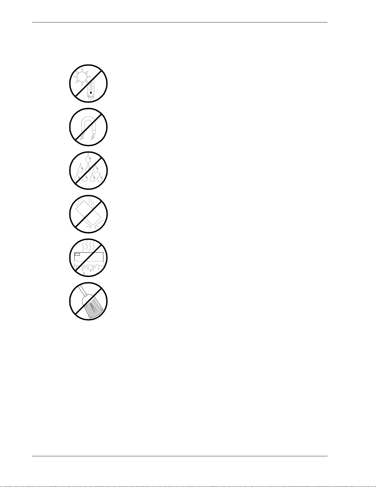
Care and Handling
Use the following guidelines to properly handle and care for your system.
Protect the system from extremely low or high temperatures. Let
the system warm (or cool) to room temperature before using it.
Keep the system away from magnetic forces.
Keep the system dry. Do not wash the system with a wet cloth or
pour fluid into it.
Protect the system from being bumped or dropped.
Check the system for condensation. If condensation exists, allow it
to evaporate before powering on the system.
Keep the system away from dust, sand, and dirt.
xii Using This Guide
Page 15

System Overview
!
Overview
!
Fault-Tolerant Hardware
!
System Chassis
!
System Components and Module Set
!
System Features
1
Page 16
Overview
This server is well suited for Symmetric Multiprocessing (SMP) and Enterprise class
network server environments and is a highly reliable, high-powered, fault-tolerant,
high-capacity multiprocessing system based on the Intel Pentium III® processor family.
It is a fully redundant system with on-line serviceability and hot plug replacement of all
major subsystems and a solid performer offering the latest technology. The server
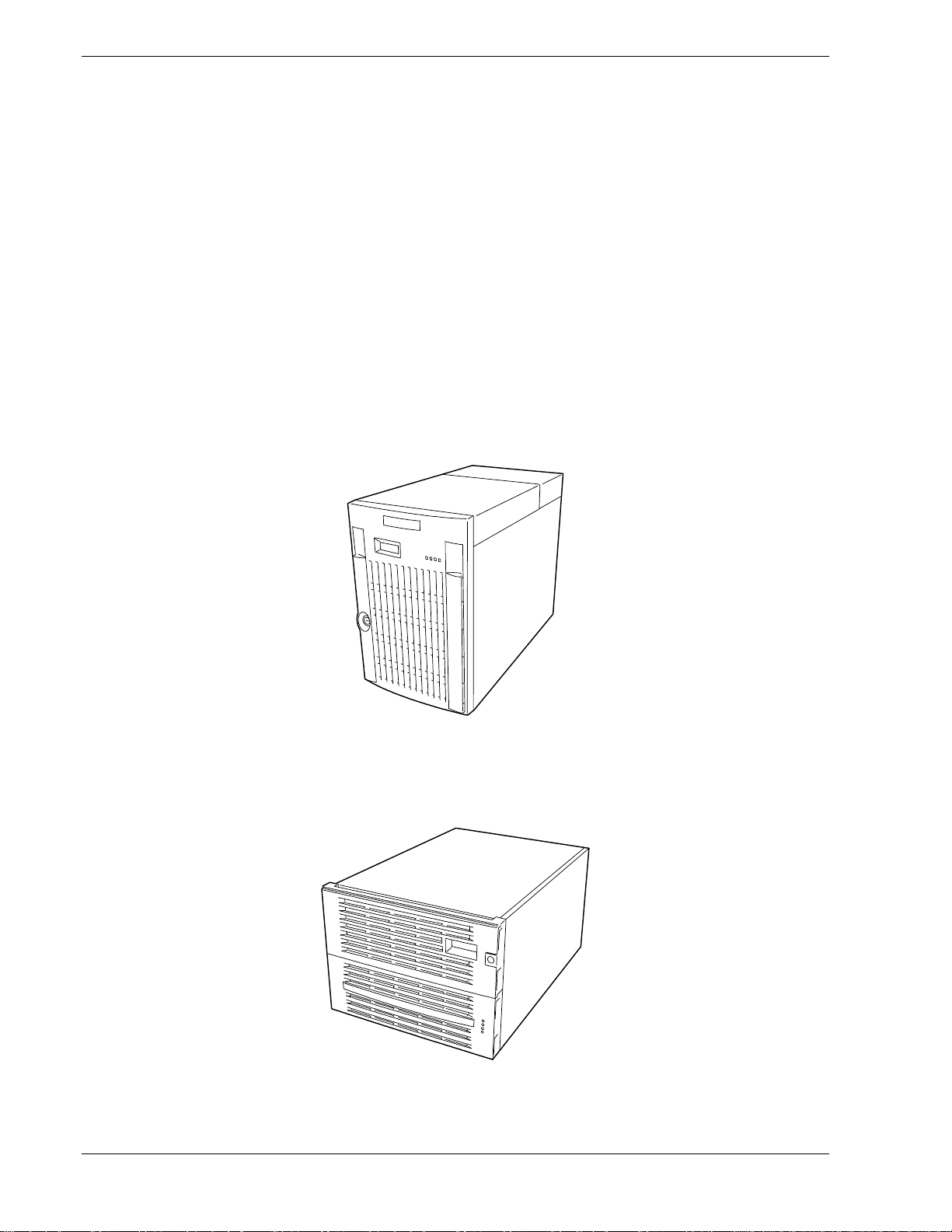
system is conveniently housed and available as a tower-based system, including
housing for the tape drive module (see Figure 1-1) or as a rack-mount system, without
housing for the tape drive module (see Figure 1-2) in a relatively small form factor of
8U (fits into a standard EIA 19-inch rack assembly.)
The combination of mirrored computing performance, memory capacity, and integrated
I/O provides a high performance environment for many applications including network
servers. The server system is designed for use in applications where fault-tolerant,
advanced technology, high performance, and high levels of reliability and compatibility
are expected.
1-2 System Overview
Figure 1-1. Tower-Based System
Figure 1-2. Rack-Mount System
Page 17

This server system is designed for full redundancy and hot plug replacement of all
major subsystems. The system modules that can be replaced are identified as Customer
Replaceable Units (CRUs) of which most are redundant and hot pluggable. To this end,
the server includes or has the option to include the following:
Two self-contained power supplies that provide redundant power (i.e., the system
!
will continue to operate with a single power supply failure) and are hot swappable.
The two power supplies are easily installed or removed from the back of the chassis
without turning the system power off.
Cooling system redundancy where the system will continue to operate in the event of
!
a fan failure and the redundant fans will switch to maximum operating speed.
SCSI hard disk drive bays accessible from the front of the chassis.
!
Hot-swap SCSI disk drive backplane; a failed drive can be removed and replaced
!
with a new drive without system power being turned off.
High degree of SCSI disk fault tolerance and advanced disk array management
!
features.
Video Graphics Array (VGA) controller with 4 MB of video memory (occupies one
!
PCI slot per PCI module).
SCSI disk adapter providing dual channel Ultra 160 SCSI interfaces for the hot swap
!
hard disk drives.
Embedded single channel enhanced IDE adapter providing interface for peripheral
!
devices (CD-ROM and super floppy disk drive).
Integrated onboard Network Interface Controller (NIC), an Intel 82559 PCI LAN
!
adapter for 10 or 100 Mbps Ethernet networks with a RJ-45 Ethernet connector.
Storage module that holds up to six hot-swap SCSI hard disk drives (three logical
!
disks).
SCSI backpanel is Ultra2 capable.
!
Integrated dual Universal Serial Bus (USB) ports that include support for the
!
keyboard and mouse.
Hardware monitors (temperature, fans, and voltage) and software monitors to
!
indicate failures.
Hardware monitors (temperature and voltage) and software monitors to indicate
!
failures.
Easy access to all parts for service.
!
System Overview 1-3
Page 18
As application requirements increase, you can expand your server system with
additional processors, additional memory, add-in boards and peripheral devices.
Your server system features the following major components:
Up to two high-performance 800 MHz Pentium III processors in a CPU module.
!
Up to 2 GB of Synchronous Dynamic Random-Access (SDRAM) system memory in
!
a CPU module.
Four PCI expansion slots, which support 32 bit PCI adapter cards in a PCI module.
!
Fault-Tolerant Hardware
The hardware architecture of the system provides fault tolerance transparency. If a
hardware component fails, the application program continues processing and is never
aware that a failure occurred.
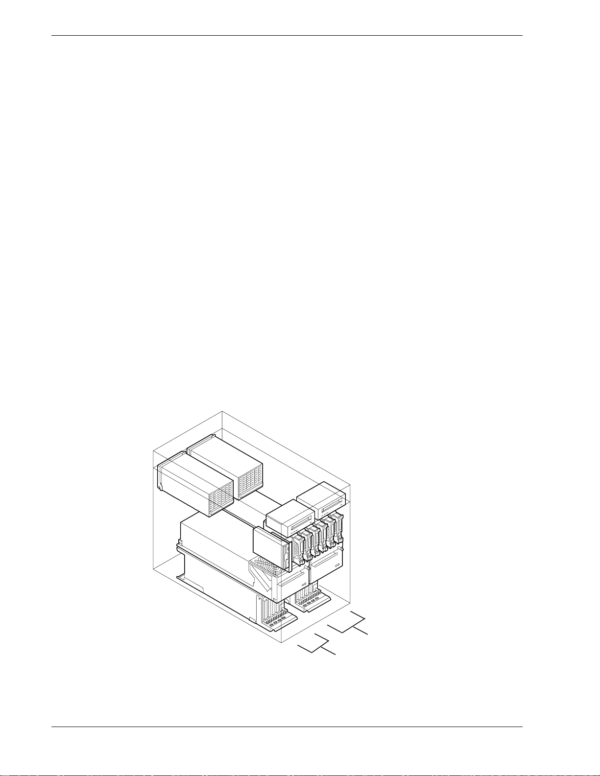
To provide system redundancy this system uses dual hardware technology. That means
that all major components are mirrored within a single hardware chassis. Group #1 is on
the left-hand side of the chassis and Group #2 is on the right-hand side of the chassis, as
viewed from the front of the chassis, see Figure 1-3. There are two CPU modules and
each CPU module is operating in lockstep (performing the same instructions at the
same time) with the other as a single system. Thus, if a failure occurs in one CPU
module the other CPU module will continue to operate with no interruption, no loss of
data, and system performance is not affected. Note that the PCI module, PCI adapters,
and power supplies are also paired for system redundancy.
Figure 1-3. Dual Hardware Fault-Tolerant Tower-Based System
1-4 System Overview
Group #2
Group #1
Page 19
System Chassis
A
The system chassis is an easy-to-expand, fabricated metal structure. The following
subsections describe the system chassis external view, internal view, and the system
board set.
External View
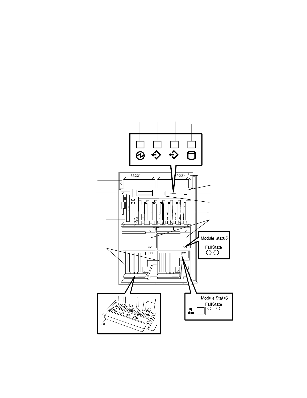
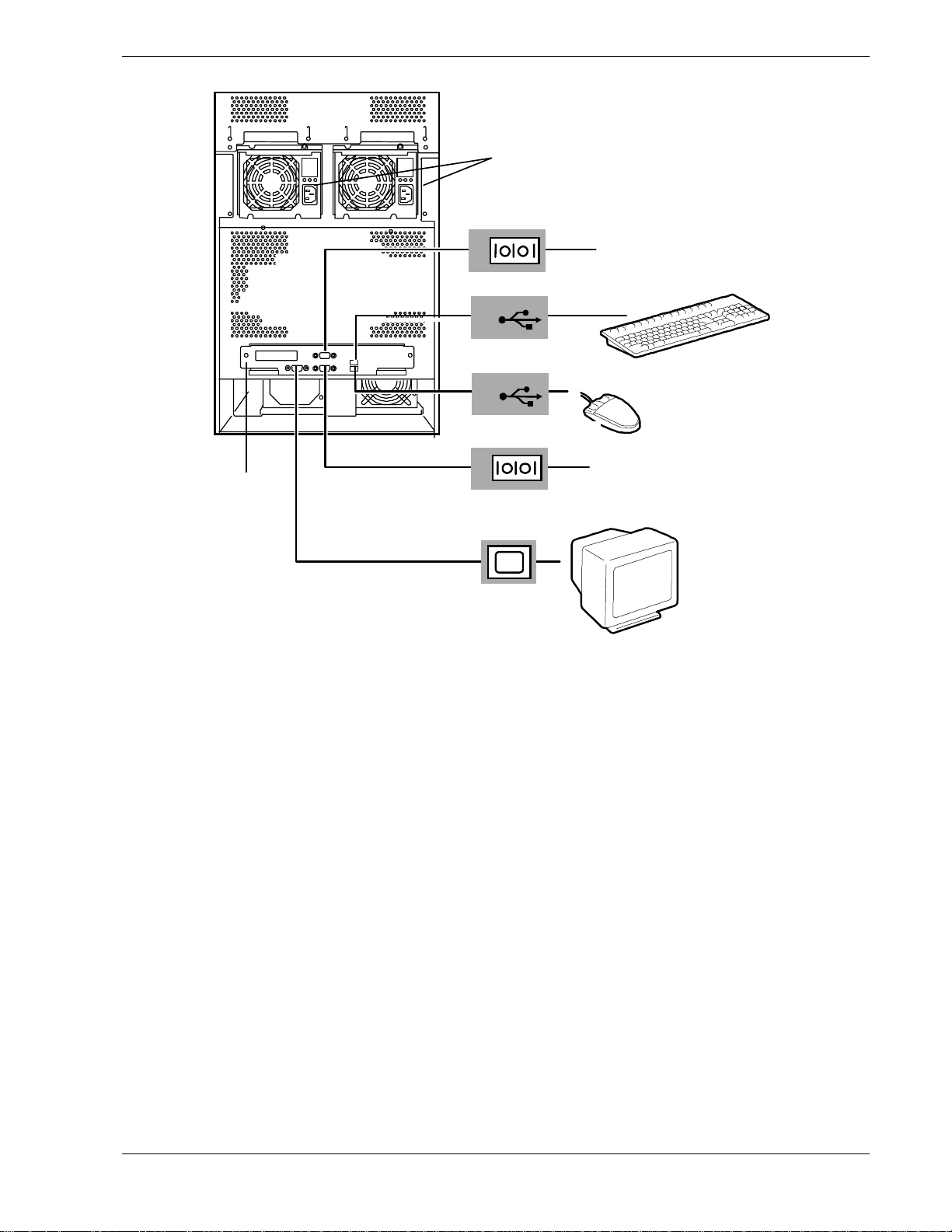
Figure 1-5 shows the front chassis features and controls. Figure 1-6 shows the rear
chassis features and controls. Figure 1-7 shows the optional tape drive bay kit
components features and controls on the rear of the chassis.
M
B
C
D
1 2
E
L
K
J
F
G
H
I
Figure 1-4. Front Chassis Features and Controls
System Overview 1-5
Page 20

– System power LED
A
– Status 1 LED (group 1)
B
Tower: Left side of system
Rack: Top of system
– Status 2 LED (group 2)
C
Tower: Right side of system
Rack: Bottom of system
– Disk activity LED
D
– Front panel
E
– USB port
F
– System power button
G
– SCSI hard disk drive bays
H
(storage bays)
– CPU modules
I
– PCI modules with PCI adapters
J
Device module
K –
Liquid Crystal Display (LCD)
L –
Tape drive module
M –
(tower system only)
When green, system power is on.
When off, system power is off.
When green, the Group 1 PCI- and CPU-modules are
operating normally. See Table 1-1 for a list and description of
the system status LED indicators.
When green, the Group 1 PCI- and CPU-CPU modules are
operating normally. See Table 1-1 for a list and description of
the system status LED indicators.
When green, internal disk drives are being accessed. See
Table 1-1 for a list and description of the system status LED
indicators.
Panel contains the LCD, the system power button, four LEDs,
and a USB port.
USB connector jack used for debug only
Press to turn system DC power on or off.
Each slot in a bay can contain one hot-pluggable 3.5-inch disk
drive.
The slots are numbered 1 – 6 left to right (numbers are not
SCSI IDs). SCSI IDs are 0, 1, and 2 for each group of three
disk drives. The drives are mirrored as follows: 1 – 4, 2 – 5,
and 3 – 6. Each drive has two status LEDs. Refer to Table 1-2
for information on disk drive status LED panel indicators.
Two CPU modules providing Dual Modular Redundancy
(DMR). The CPU modules are numbered 1 – 2 left to right.
Each CPU module contains one or two processors and a
maximum of up to 2 GB of SDRAM memory. Refer to Table
1-3 for information on CPU module status LED indicators.
Two hot-pluggable PCI modules. The PCI modules are
numbered 1 – 2 left to right. Each PCI module contains four
PCI adapter card slots and two embedded adapters (LAN and
SCSI disk). Each module has a pair of status LEDs and a
LAN port. See Table 1-4 for a list and description of the PCI
module status LED indicators. See Table 1-5 for a list and
description of the PCI adapter-slot status LEDs.
Houses an IDE 24X CD-ROM drive and 3.5-inch IDE highcapacity (120 MB) super (floppy) disk drive (not hot
pluggable).
A 2-line, 16-character display.
Displays system event messages:
Startup
!
Self-test
!
Normal operating
!
Alarm conditions
!
See Chapter 5 for a list and description of the system event
messages.
Houses the optional tape drive bay kit (that includes a 75 watt
power supply) and up to two optional 5.25-inch tape drives.
The tape drives are numbered 1 – 2, left to right.
Figure 1-5. Front Chassis Features and Controls (Continued)
1-6 System Overview
Page 21
A
G
B
1
C
1
D
2
E
2
F
– Power supplies
A
– COM1
B
– Keyboard
C
– Mouse
D
– COM2
E
– VGA (monitor)
F
– I/O panel
G
Figure 1-6. Rear Chassis Features and Controls
Two standard 450-watt power supplies. The power supplies are
numbered 1 – 2, right to left from the rear of the system. Each
power supply has three status LED indicators. Refer to Table 1-6
for information on the power supply LED indicators.
COM1 serial port 9-pin connector (for UPS option).
USB port 1.
USB port 2.
COM2 serial port 9-pin connector (for external modem option).
VGA monitor 15-pin connector.
Contains two USB ports, one VGA port, and two serial ports
(COM1 and COM2).
System Overview 1-7
Page 22
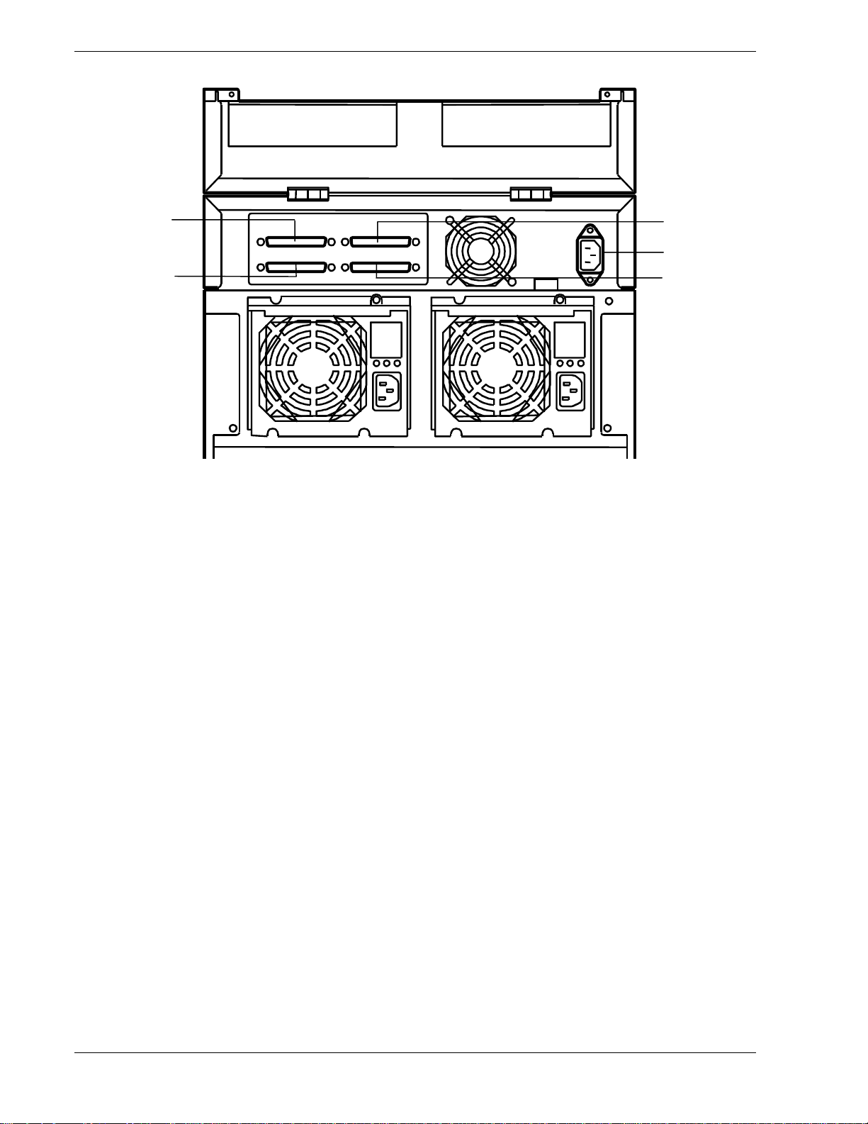
E
D
– External SCSI Device #1
A
Output Port
– AC Input Plug
B
– External SCSI Device #1
C
Input Port
– External SCSI Device #2
D
Input Port
– External SCSI Device #2
E
Output Port
A
B
C
External SCSI output port for tape drive #1.
AC input plug for 75-watt power supply.
External SCSI input port for tape drive #1.
External SCSI input port for tape drive #2.
External SCSI output port for tape drive #2.
Figure 1-7. Optional Tape Drive Bay Kit
Rear Chassis Features and Controls
Status LED Indicator Descriptions
Table 1-1 lists the system status LED indicators along with a description of each LED
indicator. Table 1-2 lists the disk drive status LED panel indicators along with a
description of each LED indicator. Table 1-3 lists the CPU module status LED
indicators along with a description of each LED indicator. Table 1-4 lists the PCI
module status LED indicators along with a description of each LED indicator. Table 1-5
lists the PCI adapter-slot status indicators along with a description of each LED
indicator. Table 1-6 lists the power supply status LED panel indicators along with a
description of each LED indicator.
The access LED indicators for the CD-ROM drive and the diskette drive light when
access is being made to the media in the drive.
1-8 System Overview
Page 23

Table 1-1. System Status LED Indicators
LED Status Description Response
System Power Off Power OFF None required (normal)
Green Power ON None required (normal)
Status 1 and
Status 2
Off AC Power OFF
Power-On Self-Test
(POST) is running
Status 1 OFF
Status 2 OFF
CPU bus error
ISA-bus I/O check error
Green
(Steady
light)
Green
(Flashing
light)
Amber
PCI and CPU modules are
operating normally
CPU or PCI module is
operating in simplex mode
Critical temperature alarm
Critical voltage alarm
None required (normal)
None required (normal)
Check Status 2
Check Status 1
Turn system off and on. If error
appears during POST, record the
error condition and contact your
technical support representative.
Turn system off and on. If error
appears during POST, record the
error condition and contact your
technical support representative.
None required (normal)
None required (normal)
If error exists, record the error
condition and contact your technical
support representative.
Check condition
Amber
(Flashing
light)
Red BMC failure One of the PCI modules is not
Disk Activity Off Not accessing disk drives None required (normal)
Amber Internal disk drive failure Check disk drive status LEDs
Green Accessing disk drives None required (normal)
Noncritical temperature
alarm
Noncritical voltage alarm
Fan alarm
Detected device failure
Detected error with
redundant power supply
Check condition
Check condition
Check condition
Contact your technical support
representative.
Check power supply status LED
indicators, see Table 1-6.
installed.
System Overview 1-9
Page 24

Table 1-2. Disk Drive Status LED Panel Indicators
LED Status Description Response
Disk Drive
Power
Disk Drive
Error
*Software controlled.
**Blinks off during disk access.
Off Disk drive
power off
Green Disk drive
power on
Green
(Flashing
light)**
Off No Fault None required (normal)
Amber
(Steady light)
(Flashing light)
Accessing disk drive None required (normal)
Disk drive failure*
Rebuilding*
Remount the disk drive
None required (normal)
Replace disk drive
None required (normal)
Table 1-3. CPU Module Status LED Indicators
Fail LED State LED Description Response
Off Green Both CPU modules are
operating normally.
Off Amber CPU module in simplex
mode is operating normally.
None required (normal)
None required (normal)
Red Green CPU module is executing
online power-on self-test
(POST)
Red Amber System is dumping memory
to disk.
Red OFF Standby (No DC, AC only)
or
CPU module failure
OFF OFF No power to CPU module. Check that the module is properly
None required (normal)
None required (normal)
Turn on system power
or
Replace CPU module.
installed. Also, check both power
supplies and power cords.
1-10 System Overview
Page 25

Table 1-4. PCI module Status LED Indicators
Fail LED State Status Description Response
Off Green Both PCI modules
are operating
normally.
Off Amber PCI module in
simplex mode is
operating normally.
Other PCI module is
offline.
Off Off No power to PCI
module.
Red Green PCI module is
running POST.
Red Off Standby mode.
(No DC power, AC
power only)
PCI module failure Check that the module is properly
Table 1-5. PCI Adapter-Slot Status LED Indicators
None required (normal)
Place the offline PCI module online
so that the system is running in
duplex mode.
Check that the module is properly
installed. Also, check both power
supplies and power cords.
None required (normal)
Turn on system power.
installed. If the condition persists,
contact your technical support
representative.
Fail LED State LED Description Response
Off Amber PCI adapter is
running in simplex
mode.
Off Green POST or PCI
adapter is running in
duplex mode.
Off Off PCI adapters are not
installed or are not
installed correctly.
Red Off PCI adapter is
installed correctly
but not working or
offline.
Red Amber PCI adapter being
tested under
software control or
preparing for
operation.
Red
Green Memory dump
request is being
issued or
diagnostics are
running.
Install identical PCI adapter in
corresponding slot in the other PCI
module.
None required (normal)
Install PCI adapters.
Place the PCI adapter online.
Wait for the LED indicator to
change. If the LED indicator does
not change, check the status of the
adapter.
Wait until the memory dump or
diagnostics are finished.
System Overview 1-11
Page 26

Table 1-6. Power Supply Status LED Indicators
LED Description Response
Power Pre-Fail Fail
Off Off Off No AC power. Check that AC power is available at
the wall outlet.
Check that the system power cords
are properly connected to the power
supplies and the AC wall outlets.
Green
(Flashing
light)
Green Off Off Power supply DC On andOKNone required (normal)
Off Off Amber Power supply failed. Replace the power supply.
Green Off Amber
Green
Off Off AC present and Standby
On.
Current limit None required (normal)
(Flashing
light)
Amber
(Flashing
light)
Off Fan failure. Replace power supply.
None required (normal)
1-12 System Overview
Page 27
Internal Board View
C
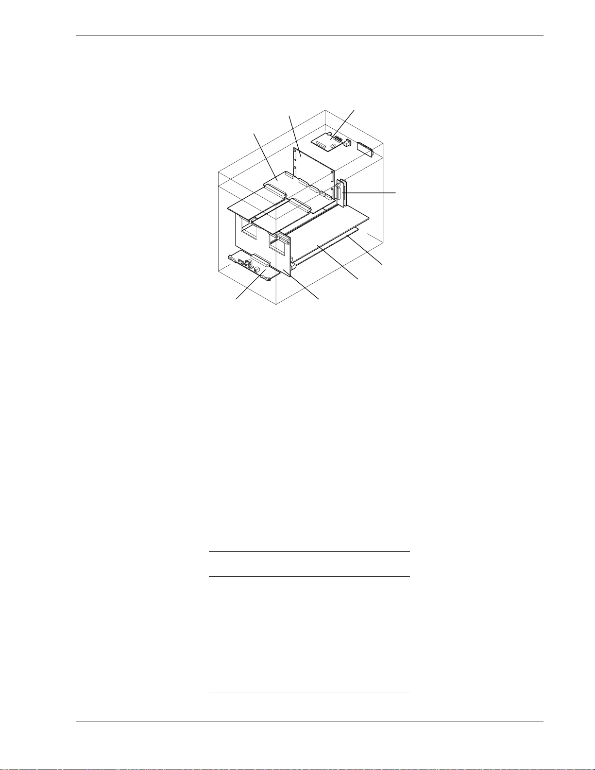
Figure 1-8 shows the major boards and backplanes inside the server.
H
G
F
A
B
C
D
E
F
G
H
Front panel board
Device backplane
(IDE device relay boards)
PCI board (located in PCI module)
CPU board (located in CPU module)
Main Backplane board
I/O panel board
Power backplane
SCSI backplane
E
A
B
D
Figure 1-8 Major Boards and Backplanes Inside the Server
Customer Replaceable Units (CRUs)
Certain hardware components within the server are defined as Customer Replaceable
Units (CRUs) of which most are hot-pluggable and redundant. Table 1-8 lists the CRUs
and whether they are hot pluggable or redundant hardware components.
Table 1-7. Customer Replaceable Units (CRUs)
CRU Redundant
CPU module Yes Yes
Device module No No
PCI module Yes Yes
Power supply Yes Yes
PCI adapter cards
Hard disk drives Yes Yes
"
Only if PCI adapter cards are identical in both PCI modules.
Yes
Hot
Pluggable
"
No
System Overview 1-13
Page 28
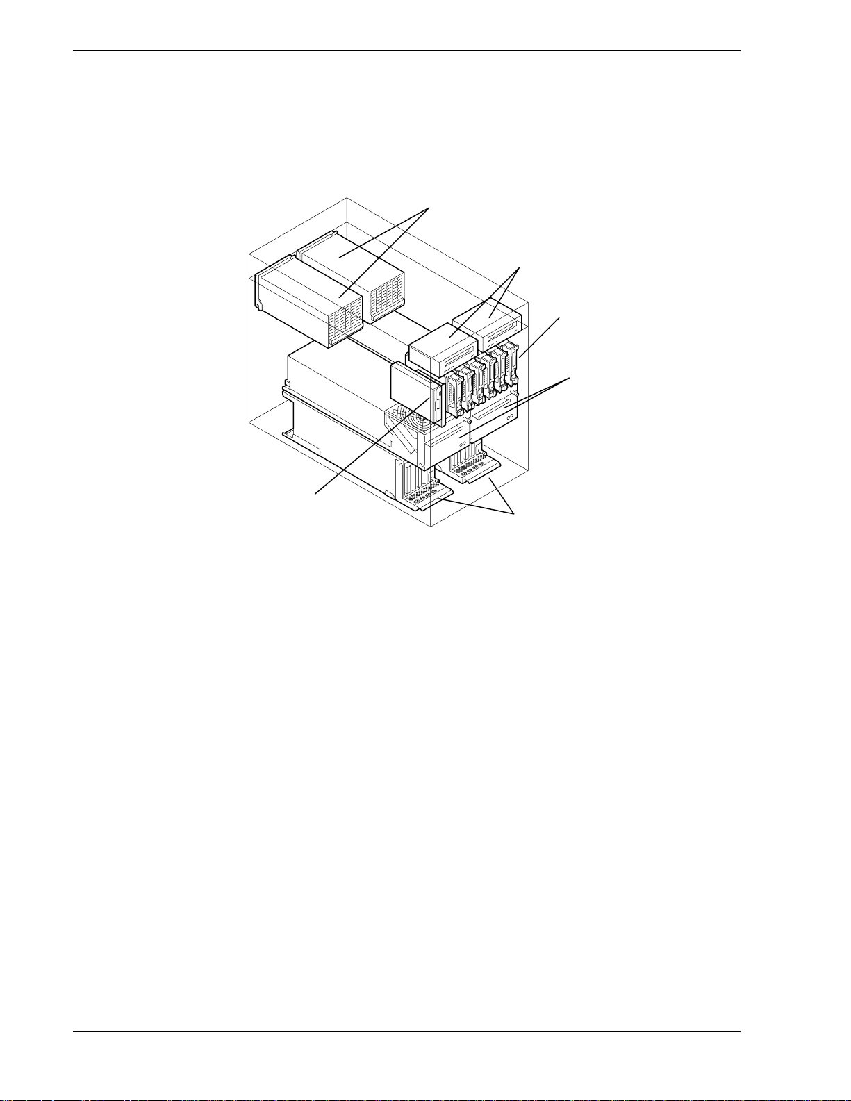
System Components and Module Set
The system components and module set inside the server are show in Figure 1-9.
A
B
C
D
Figure 1-9 System Components and Module Set Inside the Server
Power Supplies
The server has two standard 450-Watt power supplies. Each supply has autoranging
input 50/60 Hz and automatically switches between the following input voltage ranges:
100-127 VAC at 50/60 Hz; 7.6 A maximum current
!
200-240 VAC at 50/60 Hz; 3.8 A maximum current
!
F
E
A
B
C
D
E
F
Power supplies
Optional tape drives
Storage bays
CPU modules
PCI modules
Device module
The power supplies are numbered 1 and 2, right to left as seen from the rear of the
system. Both power supplies are CRUs and are hot pluggable and redundant. Each
power supply has three status indicators that are listed along with a description of each
in Table 1-6.
1-14 System Overview
Page 29
CPU Modules
The server has two CPU modules that provide Dual Modular Redundancy (DMR). The
CPU modules are numbered 1 and 2, left to right as seen from the front of the system.
Each CPU module has two status indicators that are listed along with a description of
each in Table 1-3. Table 1-8 summarizes the features of a CPU module.
Feature Description
Upgradable
multiple processor
slots
Table 1-8. Features of the CPU Module
Two processor sockets are available on the CPU board for one or two
processors.
Upgradable
memory
SMP Supports two-way Symmetric Multiprocessing (SMP) when two processors
Fan Two integrated fans that provide cooling for both the CPU module and hard
The system runs identical applications in both CPU modules in lockstep. Thus, if one
CPU module fails, the second CPU module takes over the processing without any
interruption to the current application running on the system. Note that this type of
failure is transparent to the user.
In simplex mode the system is operating with only one CPU module and one PCI
module. Thus, the failure of one CPU module or one PCI module causes the whole
system to fail. A fault-tolerant system should not run in the simplex mode for any
longer than necessary for upgrading or repair.
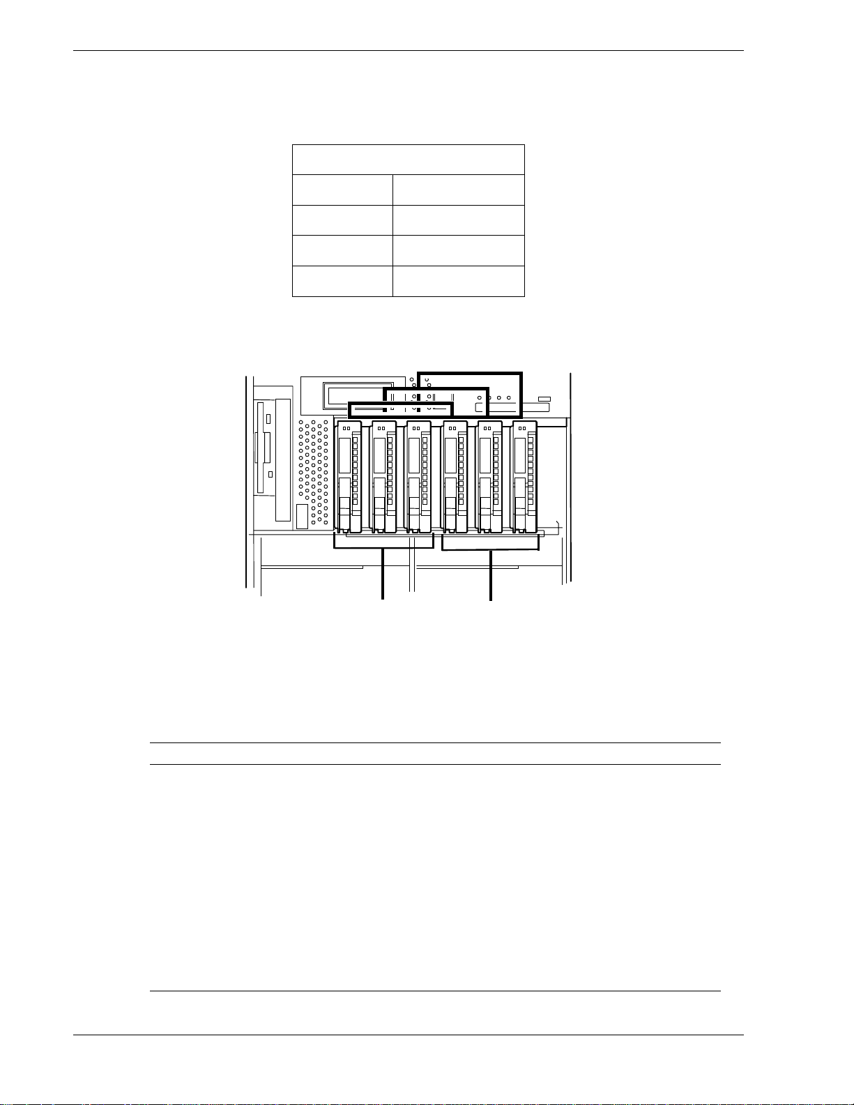
Storage Bays
The server has a storage area containing six storage bays that support six hard disk
drives (three logical disks). The hard disk drives are CRUs, hot pluggable, and
redundant. The disk slots are physically numbered 1 – 6, left to right as seen from the
front of the system. The disk drives SCSI ID numbers are 0, 1, 2 for each group of
logical disk drives and the first mirrored pairs are physical drives 1 and 4 that contain
the boot software, as shown below.
Four DIMM sockets on the CPU board. Can contain a minimum of 256 MB
up to a maximum of 2 GB of Synchronous Dynamic Random-Access
(SDRAM) system memory.
are installed.
disk drives.
SCSI ID 0
Disk #1
Group 1 Group 2
SCSI ID 1
Disk #2
SCSI ID 2
Disk #3
SCSI ID 0
Disk #4
SCSI ID 1
Disk #5
System Overview 1-15
SCSI ID 2
Disk #6
Page 30
For true dual modular redundancy, all the disk drives must be mirrored in the system, as
shown below.
Mirrored Drives
Drive Drive
14
25
36
All the disk drives must be added in pairs and only similar disks can mirror each other.
Figure 1-10.
Group 1
Group 2
Figure 1-10. Mirrored Hard Disk Drives
Table 1-9 summarizes the features of storage bays and hard disk drives.
Table 1-9. Features of the Storage Bays and Hard Disk Drives
Feature Description
Disk drives Hot pluggable and redundant.
Disk drive speeds
and storage
capacity
Disk drive carrier Each disk drive is mounted in a disk drive carrier containing a handle, latching
Storage bays The storage bays can contain any combination of disk drive carriers and
Disk drive spindle speeds of 10,000 RPM. Storage capacities of 18, or 36 GB.
mechanism, and two status indicators. The status indicators are listed along
with a description of each in Table 1-2.
dummy disk drive carriers as long as equivalent drives are mirrored.
DO NOT remove dummy disk drive carriers from unused slots. They are
present to direct airflow around the devices.
1-16 System Overview
Page 31

PCI modules
The server has two PCI modules that are CRUs, hot pluggable, and fault-tolerant. Each
PCI module contains a PCI board that transfers data from PCI devices to the CPU. The
PCI module is fault-tolerant such that if one stops functioning the other PCI module
takes over.
The PCI modules are numbered 1 and 2, left to right as seen from the front of the
system. Each PCI module has two status indicators that are listed along with a
description of each in Table 1-4. Table 1-10 summarizes the features of a PCI module.
Feature Description
PCI slots Four PCI expansion card slots are available in the PCI module.
Table 1-10. Features of the PCI module
Note that Slot 1 is reserved for a graphics video card or the SMM card.
Embedded
adapters
Network port One Ethernet port for connecting to a network from the embedded LAN
PCI Adapter Cards
For fault-tolerant systems the 32 bit PCI adapter cards must be installed in the PCI
modules as redundant pairs. This is so that if a PCI card fails in one PCI module its
equivalent PCI card in the other PCI module takes over the I/O operation without the
processing being interrupted or having any loss of data or performance.
Located on the bottom front of each PCI module are PCI adapter-slot status LEDs that
monitor the status of each PCI card. See Table 1-5 for a list and description of these PCI
adapter-slot status LEDs.
Two embedded adapters are available as follows:
– LAN
– SCSI disk
adapter.
System Overview 1-17
Page 32

Device Module
A
The device module supports two standard PC AT compatible peripheral devices (see
Figure 1-11), as follows:
One IDE 3.5-inch high-capacity super floppy disk drive (supports 720 KB, 1.44 MB,
!
and 120 MB diskette media).
One 24X CD-ROM drive.
!
B
C
A
B
C
The device module is a single CRU that is not hot-pluggable.
Optional Components
Optional components are described in the following subsections.
Tape Drives
In the tower system only, two tape drive module bays are available for mounting
optional half-height 5.25-inch tape drives. As a prerequisite to installing the optional
tape drives an optional internal device bay kit must be installed first.
The tape drives are numbered 1 and 2, left to right as viewed from the front of the
system.
Monitor, Keyboard, and Mouse
The system does not require a monitor, keyboard, or mouse for most server
management functions other than the initial boot, system upgrading, or system
troubleshooting.
High-capacity super floppy disk drive
24X CD-ROM drive
Device module
Figure 1-11. Device Module
USB-compatible keyboard and mouse connectors are available on the rear of the
system.
Support for a colored VGA monitor is also available by using the VGA monitor
connector available on the rear of the system.
1-18 System Overview
Page 33

System Features
A
The following subsections provide a description of the system features.
Pentium III Processor
Depending on system configuration, each CPU CRU can include up to two Pentium III
800 MHz processors, see Figure 1-12. Each Pentium III processor is mounted on the
CPU board located in the CPU module. The primary processor plugs into a Zero
Insertion Force (ZIF) socket on the board. The processor features a 256 KB cache. An
optional second Pentium processor III enhances performance and allows Symmetric
Multiprocessing (SMP).
B
C
F
A
CPU module
B
CPU board
C
Primary processor
D
Voltage regulator for primary processor
E
Voltage regulator for secondary processor
F
Secondary processor
D
E
Figure 1-12. Processor Locations on the CPU Board
System Overview 1-19
Page 34

System Memory
A
Up to 2 GB of Synchronous Dynamic Random-Access Memory (SDRAM) can be
configured on the CPU board located in the CPU module. The CPU board contains four
168-pin DIMM sockets allowing for system memory expansion within a CPU module.
See Figure 1-13
Note:
Call your customer service representative for information.
Only use DIMMs approved for use in this server system.
B
C
A
B
C
D
D
CPU module
CPU board
Memory socket #1
Memory socket #4
SAF-TE Controller
The SCSI Backplane has two SAF-TE (SCSI Accessed Fault Tolerant Enclosure)
controllers that provide an interface to a disk subsystem that supports status signals, hot
swapping drives, and module monitoring.
The transport mechanism for the standardized alert detection and status reporting is the
SCSI bus. Disk drives, power supplies, cooling fans, and temperature are continually
monitored and the conditions then reported over the SCSI bus to the system. This
allows the user to react to conditions that could normally go unnoticed until data loss.
Figure 1-13. DIMM Locations on the CPU Board
1-20 System Overview
Page 35

BIOS
The BIOS and Setup Utility are located in the Flash EPROM on the CPU board and
include support for system setup and legacy device configuration. A number of security,
reliability, and management features also have been incorporated to meet vital server
needs.
USB/IDE Controller
The ServerWorks ROSB chip supports the USB and IDE controllers. The I/O panel
board provides the connector interface for two USB ports that support the keyboard and
mouse.
The system includes a single channel enhanced IDE 32 bit interface. The IDE controller
provides support for the internally mounted CD-ROM and super floppy disk drive.
The device controls:
PIO and DMA transfer modes
!
Mode 4 timings
!
Transfer rates up to 33 MB/s
!
Buffering for PCI/IDE burst transfers.
!
Network Controller
Each PCI CRU includes a 10BASE-T/100BASE-TX network controller based on the
Intel 82559 Fast Ethernet Network Interface ASIC. As a PCI bus master, the controller
can burst data at up to 132 MB/sec. The controller contains two receive and transmit
FIFO buffers that prevent data overruns or underruns while waiting for access to the
PCI bus. The controller has the following:
32-bit PCI bus master interface (direct drive of bus), compatible with PCI Bus
!
Specification, Revision 2.1
Chained memory structure with improved dynamic transmit chaining for
!
enhanced performance
Programmable transmit threshold for improved bus utilization
!
Early receive interrupt for concurrent processing of receive data
!
On-chip counters for network management
!
Autodetect and autoswitching for 10 or 100 Mbps network speeds
!
Support for both 10 Mbps and 100 Mbps networks, capable of full or half
!
duplex, with back-to-back transmit at 100 Mbps
Support for Wake On LAN.
!
System Overview 1-21
Page 36

SCSI Controller
The PCI board includes an embedded QLogic ISP12160A SCSI dual channel controller
for supporting the hard disk drives in the storage bays. It is a 64-bit direct memory
access (DMA) bus master and supports 32-bit PCI buses at 33 MHz. This SCSI
controller interfaces the PCI bus to two Ultra 160 SCSI buses. The SCSI controller is
fully autonomous and capable of managing multiple I/O operations and data transfers
without host intervention.
Video Controller
The system has an integrated Intel 69000 HiQVideo Accelerator highly integrated
graphics controller that supports the following:
BIOS compatibility with 1/4VGA, VGA, SVGA, XGA, and SXGA
!
2 MB of onboard synchronous DRAM (SDRAM) embedded memory
!
Superb 2D video performance
!
Analog VGA monitors (single and multiple frequency, interlaced and
!
noninterlaced) with a maximum vertical retrace noninterlaced frequency of
100 Hz.
Peripheral Controller
The Super I/O PC97317 integrated peripheral controller supports two enhanced serial
ports (UARTs) and an integrated Real Time Clock (RTC) module. The I/O panel board
provides the connector interface for each serial port.
Serial Ports
The serial ports (UART1 and UART 2) provide data rates up to 1.5 Mbaud and 13 IRQ
channel options. When disabled, serial port interrupts are available to add-in boards.
Real Time Clock
The real-time clock (RTC), which is located in the PCI module on the PCI board,
provides system clock/calendar information stored in a non-volatile memory
(NVRAM). The real-time clock battery provides power backup for the real-time clock.
See Figure 1-14.
The RTC battery may need to be replaced because of its battery life span. The battery
powers the clock in the absence of power. When the battery starts to weaken, it loses
voltage, and the system settings stored in CMOS RAM (for example, the date and time)
may be wrong.
The RTC battery (Vendor Part No. CR2032) is available through many vendors.
Contact your sales representative or dealer for a list of approved devices.
1-22 System Overview
Page 37

A
B
C
A
PCI module
B
PCI board
C
Real-time clock battery
Figure 1-14. Real-Time Clock Battery
System Overview 1-23
Page 38

Baseboard Management Controllers (BMC)
Server management is concentrated in the Baseboard Management Controllers (BMC).
The BMCs and associated circuitry are powered from a 5Vdc standby voltage, which
remains active when system power is switched off, but the ac power source is still on
and connected.
The BMC supports the Management Workstation Application (MWA), which allows
remote server management via a modem, LAN, or direct connection to a manager
system. Events monitored by the manager system include over-temperature and overvoltage conditions, fan failure, or chassis intrusion.
Information on the Management Workstation Application (MWA) in the ESMPRO
Suite User’s Guide on the ESMPRO CD-ROM.
One major function of the BMC is to autonomously monitor system management
events, and log their occurrence in the nonvolatile System Event Log (SEL). The events
being monitored include overtemperature and overvoltage conditions, fan failure, or
chassis intrusion. To enable accurate monitoring, the BMC maintains the nonvolatile
Sensor Data Record (SDR), from which sensor information can be retrieved. The BMC
provides an ISA host interface to SDR sensor information, so that software running on
the server can poll and retrieve the server's current status.
The BMC performs the following:
Monitors server board temperature and voltage
!
Monitors processor presence and controls Fault Resilient Boot (FRB)
!
Detects and indicates baseboard fan failure
!
Manages the SEL interface
!
Manages the SDR Repository interface
!
Monitors the SDR/SEL timestamp clock
!
Monitors the system management watchdog timer
!
Monitors the periodic SMI timer
!
Monitors the event receiver
!
Controls secure mode, including video blanking, diskette write-protect monitoring,
!
and front panel lock/unlock initiation
Controls Wake On LAN via Magic Packet support.
!
External Device Connectors
The external device I/O connectors located on the I/O panel board (see Figure 1-15)
provide support for two USB ports that support a mouse and a keyboard, two serial port
connectors, and a VGA monitor port.
1-24 System Overview
Page 39

A
B
C
D
E
A
B
C
D
E
COM1 serial port (for UPS option)
USB port 1 (for keyboard)
USB port 2 (for mouse)
COM2 serial port (for external modem option)
VGA monitor port
Figure 1-15. I/O Panel External Connectors
The external device I/O connectors located on each PCI module (see Figure 1-16)
provide support for a LAN port and PCI board device ports.
A
F
E
A
B
C
D
E
F
D
PCI module 2
External LAN port
External PCI device connector
PCI module 1
External LAN port
External PCI device connector
C
B
Figure 1-16. PCI module External Connectors
System Overview 1-25
Page 40

1-26 System Overview
Page 41

Setting Up the System
!
Overview
!
Selecting a Site
!
Unpacking the System
!
Rack-Mount System Assembly
!
Getting Familiar with the System
!
Making Connections
!
Connecting the Power Cord(s)
!
Using the System
2
Page 42

Overview
This chapter describes how to select a site, unpack the system, make cable
connections, and power on the tower-based or rack-mount system units. Also,
provided are the instructions for assembling the rack-mount system unit.
Selecting a Site
The system operates reliably in a typical office environment.
Choose a site that is:
Near grounded, three-pronged power outlets.
!
Note
: For the United States and Canada, this means a
NEMA 5-15R outlets for 100-120 VAC or NEMA 6-15R
outlets for 200-240 VAC. For other international sites, this
means three-pronged power outlets applicable for the
electrical code of the region.
Be sure the power service connection is through a properly
grounded outlet.
!
WARNING
!
CAUTION
The power plug from each of the power supplies must be
plugged into the same common ground power outlets.
Clean, dust-free, and well ventilated. Front and rear ventilating openings
!
kept free of obstructions. Away from sources of heat, vibration or
physical shock.
Isolated from strong electromagnetic fields and electrical noise produced
!
by electrical devices (such as air conditioners, large fans, large electric
motors, radio and TV transmitters, and high-frequency security devices)
Spacious enough to provide at least 15 inches (38.1 centimeters) behind
!
and on each side of the system and at least 32 inches (81.3 centimeters) in
front of the system for proper cooling, airflow, and cable clearance.
Easily accessible for system maintenance and installation of system
!
upgrades.
2-2 Setting Up the System
Page 43

Unpacking the System
A
!
WARNING
Your system weighs approximately 132 pounds (60 kg). If
your system contains numerous optional boards and
peripheral devices, it will weigh more. To avoid personal
injury, make sure you have someone help you lift or move
the system.
When you receive your system if the shipping boxes are damaged, note the
damage, and if possible, photograph it for reference. After removing the
contents of the containers, keep the cartons and the packing materials. If the
contents appear damaged when you unpack the boxes, file a damage claim with
the carrier immediately.
Rack-Mount System Assembly
This section provides the instructions for assembling the rack-mount server unit
into a standard EIA 19-inch rack cabinet.
Unpacking the Rack Mounting Hardware
Although the rack mounting hardware is inspected and carefully packaged at the
factory, damage may occur during shipping. Follow these steps for unpacking.
1. Visually inspect the shipping containers; notify your carrier immediately of
any damage.
2. Carefully remove the rack mounting hardware and verify the parts. See
Figure 2-1 and Table 2-1. If parts are missing or the hardware is damaged,
notify your service representative.
C
B
D
Figure 2-1. Rack Mounting Hardware
Setting Up the System 2-3
Page 44

Before You Begin
Before you begin, please review the following cautions, warnings, and general
guidelines.
Be sure that power to the system is turned off and
unplugged. All voltage is removed only when the power
cords are unplugged.
Avoid excessive vibration and shock. Dropping an electronic component
!
can cause serious damage.
Table 2-1. Rack Mount Parts
Reference Description
A Rail Assemblies (2)
B Front Bezel (Top and Bottom Panels)
CKey
D Miscellaneous Hardware
!
WARNING
Do not disconnect or remove parts other than those specified in the
!
procedure.
Do not touch I/O connector pins.
!
All screws are Phillips-head, unless otherwise specified.
!
On completion of any assembly or reassembly, perform a power-on test.
!
If a fault occurs, verify that the assembly or reassembly was performed
correctly. If the problem persists, see "Problem Solving" in Chapter 5.
Static Precautions
An electrostatic discharge (ESD) can damage disk drives, option boards, and
other components. You can provide some ESD protection by wearing an
antistatic wrist strap attached to chassis ground when handling system
components.
Electronic devices can be easily damaged by static electricity. To prevent
damage, keep them in their protective packaging when they are not installed in
your system.
2-4 Setting Up the System
Page 45

Assembly
The following subsection describes how to assemble your rack-mount server
unit into a standard EIA 19-inch rack cabinet.
Before you begin select an appropriate location in your rack cabinet for the
rack-mount server unit. To improve rack stability, mount heavier items towards
the bottom of the rack cabinet. If the rack is a stand-alone unit and the rack is
more than 75% filled with components, consider installing an optional stabilizer
kit.
!
CAUTION
Ensure that the location of the rack-mount server unit does
not create an unstable condition when installed in the rack
cabinet.
Note:
rack cabinet you should consider the length of the cables
that interconnect system components.
A
NCHOR THE EQUIPMENT RACK
anchored to an unmovable support to prevent it from falling
over when one or more servers are extended in front of it on
slide assemblies. The anchors must be able to withstand a
force of up to 113 kg (250 lbs.) You must also consider the
weight of any other device installed in the rack.
M
AIN
installing an AC power disconnect for the entire rack unit.
This main disconnect must be readily accessible, and it must
be labeled as controlling power to the entire unit, not just to
the server(s).
G
ROUNDING THE RACK INSTALLATION
an electrical shock hazard, you must include a third wire
safety grounding conductor with the rack installation. If a
server power cord is plugged into an AC outlet that is part of
the rack, then you must provide proper grounding for the
rack itself. If server power cords are plugged into wall AC
outlets, the safety grounding conductor in each power cord
provides proper grounding only for the server. You must
provide additional, proper grounding for the rack and other
devices installed in it.
When planning your system configuration for the
!
WARNING
: The equipment rack must be
AC
POWER DISCONNECT
: You are responsible for
: To avoid the potential for
Setting Up the System 2-5
Page 46

!
CAUTION
Temperature: The operating temperature of the server unit,
when installed in an equipment rack, must not go below 5 °C
(41 °F) or rise above 35 °C (95 °F). Extreme fluctuations in
temperature can cause a variety of problems in your server.
It is recommended that the ambient temperature for a rackmount unit not exceed 25°C.
Ventilation: The equipment rack must provide sufficient
airflow to the front of the server unit to maintain proper
cooling. It must also include ventilation sufficient to exhaust
a maximum of 3,000 Btu's per hour for the server. The rack
selected and the ventilation provided must be suitable to the
environment in which the server will be used.
Mounting the Rail Assemblies into the Rack Cabinet
Before you can mount the server unit in the rack cabinet, you must install the
rail assemblies in the rack cabinet.
Note:
the rack cabinet before mounting the server unit into it.
Observe all safety precautions, warnings, and cautions
noted throughout this chapter.
You must use the following procedure to prepare
Use the following procedure to install the rail assemblies into the rack cabinet.
1. Determine where you want to install the server unit in the rack cabinet.
To improve rack stability, mount the server unit towards the bottom of
!
the rack cabinet.
If there are units already installed, install the server unit into the next
!
empty space from the bottom of the rack cabinet.
2. Starting at the bottom of the rack cabinet, or at the top or bottom of a
previously mounted unit, measure the number of screw hole locations on the
front vertical mounting rails and rear vertical mounting rails (see Figure 2-2)
for the rail assemblies. Mark the location with a pencil on the outside of both
the front and rear vertical mounting rails.
Note:
the rack vertical mounting rail are equal to 1U (1.75 inches).
For vertical reference, every three screw holes on
2-6 Setting Up the System
Page 47

A
A
A
A
B
C
C
B
A – M5 Cagenuts for ServerUnit
Faceplate
B – Rail Assembly Bracket
Alignment Tabs
C
– Rail Assembly Bracket
M5 Screw Holes
Figure 2-2. Locating and Marking the Front Mounting Holes for the Server Unit
3. While marking the hole locations for the rail assemblies, also mark the
locations on the front vertical mounting rails for the cage nuts, which hold
the thumbscrews of the server faceplate (see Figure 2-2).
4. Insert six M5 cage nuts in their marked locations on the front vertical
mounting rails (see Figure 2-3), as follows:
Position the cage nut on the inside of the front vertical mounting rails.
!
Hook the side lip of a cage nut into the square hole in the rail.
!
Squeeze while pressing the other side lip of the cage nut into the square
!
hole in the rail until it is secured.
Repeat for each cage nut.
!
Setting Up the System 2-7
Page 48

Figure 2-3. Inserting the Cage Nuts
A
5. Locate the two rail assemblies. Each rail assembly consists of an outer
bracket and an inner bracket (see Figure 2-4). The rail assembly attaches to
the rack cabinet.
C
B
A – Outer bracket
B – Inner bracket
C – Screws (8)
Figure 2-4. Rail Assembly
6. Loosen the eight screws that secure their outer and inner brackets together so
that they can slide fairly easy (see Figure 2-4).
7. Align the right rail assembly behind the mounting holes in the vertical
mounting rail (see Figure 2-5) located on the right side of the rack cabinet.
The tabs on the front and rear of the rail assembly help to align it with the
holes in the vertical-mounting rail.
2-8 Setting Up the System
Page 49

Note:
A
assemblies, the bottoms of the assemblies have a wider
offset than the top.
For correct mounting orientation of the rail
8. Install two screws (see Figure 2-5) that secure the front of the rail assembly
to the vertical-mounting rail and tighten loosely.
9. Carefully align the rear holes of the rail assembly with the holes in the rear
vertical-mounting rail.
10. Install two screws that secure the rear of the rack assembly to the vertical-
mounting rail.
11. Tighten all four screws holding the rail assembly to the vertical mounting
rails.
Note:
inner brackets may need to be readjusted.
The screws in the oblong slots of the outer and
12. Tighten the eight screws securing the two brackets together (see Figure 2-6).
13. Repeat steps 5 through 10 for the left side rail assembly.
B
C
D
A – Vertical mounting rail
B – Alignment tab
C – Screws (2)
D – Right rail assembly
Figure 2-5. Installing the Right Rail Assembly into the Rack Cabinet
Setting Up the System 2-9
Page 50

C
B
B
A
A
– Outer bracket
B – Screws (8)
C – Inner bracket
Figure 2-6. Securing the Rail Assembly Outer and Inner Brackets
2-10 Setting Up the System
Page 51

Mounting the Server Unit in the Rack Cabinet
Use the following procedure to mount the server unit into the rack cabinet.
!
WARNING
Anchor the Rack Cabinet. The rack cabinet must be
anchored to an unmovable support or a front stabilizer to
prevent it from falling over when one or more units are
extended in front of it on slide assemblies. The anchors must
be able to withstand a force of up to 113 kg (250 lbs.). You
must also consider the weight of any other device installed in
the rack.
Avoid Injury. It is required that at least two people are
present when lifting and assembling the rack-mount server
unit into a rack cabinet.
Do not attempt to lift or move the server unit by its front
faceplate or the latches on its power supplies.
1. Use a mechanical assist unit or someone to assist you to carefully lift the
server unit onto the two rail assemblies and slide it toward the rear of the
rack cabinet. See Figure 2-7.
Figure 2-7 Mounting the Server Unit
2. Secure the front bezel to the rack cabinet's front vertical mounting rails using
the eight screws and plastic washers provided.
Setting Up the System 2-11
Page 52

B
A
– Right-hand side mounting screws and washers (4)
B – Left-hand side mounting screws and washers (4)
A
Figure 2-8 Securing the Server Unit
2-12 Setting Up the System
Page 53

Getting Familiar with the System
Before setting up your system, see System Overview in Chapter 1 of this User's
Guide to become familiar with the system’s characteristics, such as the location
of your system's front and rear panel switches, indicators and connectors, etc.
Making Connections
If your system normally operates without a video display or keyboard (for
example, as a network server), you must install a video display and keyboard to
configure the system. You may remove them after running the BIOS Setup
Utility. For information on running the BIOS Setup Utility, refer to Chapter 3
Configuring Your System of this User’s Guide.
Connect your keyboard, monitor, and mouse; see Figure 1-5 in Chapter 1 of this
User's Guide. Connect any external peripheral devices such as a modem by
following the instructions included with these devices.
!
CAUTION
Inserting a telephone line connector into a LAN board RJ-45
port may result in personal injury and equipment damage.
Connecting the Power Cord(s)
Plug the female end of each AC power cord into the input receptacle(s) on the
rear of the server unit chassis (see Figure 2-9). Plug the male end of the power
cord into NEMA 5-15R outlet for 100-120 VAC or NEMA 6-15R outlet for
200-240 VAC or optional UPS AC outlets. Most optional Uninterruptible Power
Source (UPS) units have a 30 amp plug that requires a special L5-30R outlet
(see Figure 2-10) to be plugged into a 100-120 VAC outlet.
If the power cord(s) supplied with the system are not compatible with the AC
wall outlet in your region, obtain a suitable power cord that meets the following
criteria.
The power cord must be rated for the available AC voltage and have a
!
current rating that is at least 125% of the current rating of the system.
The power cord connector that plugs into the wall outlet must be
!
terminated in a grounding-type male plug designed for use in your region.
It must have certification marks showing certification by an agency
acceptable in your region.
The power cord connector that plugs into the system must be an IEC-
!
type CEE-22 female connector.
The power cord must be less than 1.8 meters (6.0 feet) long.
!
Setting Up the System 2-13
Page 54

After the power cords are plugged in confirm that the power status lamp on the
power units flashes. If the lamp is off, a failure occurred in the power unit, see
Table 1-1 System Status LED Indicators in Chapter 1 of this User's Guide.
When connecting the power cord to a power control unit, such as an UPS
confirm that the power control unit is powered off. Connecting the power cord
while power is supplied to the power control unit may cause a failure.
!
WARNING
Your system shipped with a power cord for each power
supply. Do not attempt to modify or use the supplied AC
power cord if it is not the exact type required.
!
CAUTION
The power plug from each of the power supplies must be
plugged into the same common ground power outlets.
Figure 2-9. Connecting the AC Power Cord to the Server Unit
2-14 Setting Up the System
Page 55

Figure 2-10. UPS AC Power Cord with 30 amp plug (L5-30P)
Setting Up the System 2-15
Page 56

Using the System
The following subsections describe how to use this server system properly and
safely, including an explanation of the server system power on/off sequences,
what the POST program checks in the server, how to perform a forced power
shutdown, and how to reset the system.
When using the server system the following precautions should be observed.
Make sure you power off the server before connecting or disconnecting
!
cables between the server and peripheral devices. Connecting or
disconnecting the cables while the server is powered on may cause
malfunction or failures within the server.
Verify that the access lamp on the floppy disk drive is unlit before turning
!
off the server or ejecting the floppy disk. Turning off the server or
ejecting the floppy disk while the access lamp is lit may damage data
being stored on the floppy disk.
After turning off the server, wait at least 40 seconds before turning it on
!
again. Cycling the power immediately may cause malfunction or failures
of the server.
Before relocating the server unit, turn off the power and unplug the power
!
cords from the outlet. Moving the server unit when it is powered may
cause malfunction or failures of the server.
Some software includes a command to eject the CD-ROM tray. Make
!
sure that the front door (tower-based system) or front panel (rack-mount
system) of the server unit and the front door of the rack cabinet are
opened before running the command. Running this command with any
door or panel closed may cause the CD-ROM tray to hit against it,
resulting in a possible failure of the CD-ROM or power supply.
Clean the server regularly. Regular cleaning prevents failures of the
!
server and its components.
Lightning may cause a momentary voltage drop. To prevent this problem,
!
an optional uninterruptible power supply unit is recommended.
Only use options qualified by NEC for the server. An unqualified option
!
may be mounted or connected to the server, but it may fail to operate
normally or even cause failures. Note that damage resulting from
installation of unapproved devices is not covered under warranty.
2-16 Setting Up the System
Page 57

System Power
Low-level power is always present in the server system when the server unit is
plugged into an AC source. This low-level standby power allows the BMC
controller to monitor the status of the system components even when the system
power is off.
The system power button functions as follows:
If: Then pressing the power button:
System power = off
Powers on the system and boots the OS.
Standby power = on
System power = on Powers off the system, but standby power
remains on.
Powering On the Server System
Power on your server system as follows.
1. Make sure all external devices, such as a video display, keyboard, and
mouse have been connected, and the power cords are connected.
2. Power on the video display and any other external devices.
Note:
a power control unit such as an UPS (Uninterruptive Power
Supply) make sure that the power control unit is powered on.
3. Lift the plastic cover protecting the system's power on/off switch and press
the push-button (see Figure 2-11) to power on the system and boot the
operating system. Verify that the server power-on LED is lit.
If the server unit's power cords are connected to
B
A
A
Power on/off switch
B
Power-on LED
Figure 2-11. Power On/OFF Switch and Power-On Indicator
Setting Up the System 2-17
Page 58

After a few seconds your system begins the internal Power-On Self Tests
(POST). POST automatically checks the system CPU modules, system PCI
modules, ECC memory modules, keyboard, mouse, and most installed
peripheral devices. POST also displays the start messages of the BIOS setup
utility during execution.
The POST check results should be checked in the following cases:
When the server is being used for the first time.
!
When the server appears to fail.
!
When the server beeps many times between power-on and OS start-up.
!
When an error message appears on the display unit.
!
Note:
unit, refer to subsection POST Error Codes and Messages in
Chapter 5 of this Guide.
Always allow POST to complete before powering down your
system.
For error messages that appear on the display
!
CAUTION
If you have problems powering on your system, refer to Problem Solving in
Chapter 5 of this User’s Guide.
After you have successfully powered on your system, refer to the preloaded
system Software Notes document shipped with your system
Powering Off the Server System
When server system power is on, pressing the push-button power on/off switch
on the front panel of the server turns the power off.
To turn the server system's power off:
1. Shutdown the operating system (OS).
Note:
shut down completely.
Avoid turning off system power before the OS has
2. If running W2KAS, the system should automatically power off. If not, then
press the power button (see Figure 2-11).
The power-on LED goes out.
Note:
displayed on the LCD panel during power-off.
Check to see that no error messages are
The system power is off, but standby power remains on.
2-18 Setting Up the System
Page 59

3. Power off the peripheral devices.
Note:
control unit such as an UPS (Uninterruptible Power Supply),
refer to the UPS user's guide for proper power-off
procedures.
If the server power cord is connected to a power
Forcing a Power Shutdown
A forced power shutdown can be used when the system's power on/off switch
does not power off the server or the reset functions do not work.
To perform a forced power shutdown:
Press in on the push-button power on/off switch located on the front
panel of the server for at least 4 seconds to force the server power off.
To power on after a forced shutdown, wait 10 seconds and then power on again.
Resetting the System
To do this: Press:
Soft boot reset, which clears system memory and reloads the operating system. <Ctrl+Alt+Del>
Cold boot reset, which clears system memory, restarts POST, reloads the
operating system, and halts power to all peripherals.
Power off/on
Setting Up the System 2-19
Page 60

2-20 Setting Up the System
Page 61

Configuring Your System
!
Configuring Your System
!
BIOS Setup Utility
!
Fast!Util Utility
!
Configuring System Jumpers
3
Page 62

Configuring Your System
Configuration and setup utilities are used to change your system configuration.
You can configure your system, as well as option boards you may add to your
system, using the BIOS Setup Utility. Several unique system parameters are
configured using the BIOS Setup, which is stored in the system FLASH
memory.
The Fast!Util Utility is used if you need to configure either of the SCSI
controllers in your system or to perform a SCSI disk format or verify disk
operation of these drives.
If your system has been factory configured, the BIOS Setup or Fast!Util Utility
do not need to be run unless you want to change the password or security
features, add certain types of option boards or devices, or upgrade your system
board.
This chapter also provides information on several system configuration
parameters that are set by jumpers on the system board. However, these
parameters do not usually require change.
Use the EXPRESSBUILDER CD-ROM to create the device driver diskettes.
3-2 Configuring Your System
Page 63

BIOS Setup Utility
The BIOS Setup Utility is used to change system configuration parameters. The
utility is resident in the system FLASH memory and does not require a diskette
or an operating system present to run.
Using the BIOS Setup Utility
You access the BIOS Setup utility when you turn on or reboot your system. To
run the BIOS Setup Utility, perform the following procedure:
1. Power-on or reboot the system.
2. If the NEC logo appears, press ESC in order to display POST information.
3. “Press <F2> to enter SETUP” displays.
4. Press F2. After a short period of time the BIOS Setup Utility starts and the
Main Menu is displayed. The menu bar at the top of the Main Menu lists the
following selections:
Menu Use
Main Use this menu for basic system configuration.
Advanced Use this menu for setting the Advanced Features available on
your system.
Security Use this menu to set User and Supervisor Passwords and the
Backup and Virus-Check reminders.
System Hardware Use this menu for configuring unique Server features.
Boot Use this menu to configure Boot Device priority.
Exit Exits the current menu.
Use the arrow keys to select a menu or an item on a displayed menu. Press
the value keys (see Table 3-1) to cycle through the allowable values for the
selected field. Use the Exit menu’s “Save Values” selection to save the
current values on all the menus.
To display a submenu, position the cursor on a selection that has a submenu
and press ENTER. An arrow precedes selections with submenus.
Refer to Table 3-1 for information on the value keys that you use with BIOS
Setup. These keys are also listed at the bottom of the Setup menu.
Configuring Your System 3-3
Page 64

Table 3-1 Setup Menu Value Keys
Key Function in Setup Menu
F1 or Alt-H Get Help about an item.
ESC Exit the current menu and return to the previous menu.
Left or right arrow keys Move between menus.
Up or down arrow keys Move cursor up and down. The cursor moves only to the
settings that you can change.
HOME or END Move cursor to top or bottom of window.
PAGE UP or PAGE DOWN Move cursor to next or previous page.
F5 or - Select the previous value for the field.
F6 or + or SPACE Select the next value for the field.
F9 Load default configuration values for this menu.
F10 Save configuration values and exit.
ENTER
Execute command or Select ➨ submenu.
BIOS Setup Configuration Settings
The BIOS Setup Configurations tables show the default settings for the BIOS
Setup Utility and provides a place for you to record any changes you make to
these settings. Recommended values are bold in the following tables.
3-4 Configuring Your System
Page 65

Main Menu
Choices or
Feature
Processor Type ——————— (Display Only). Shows the
Processor Speed XXX MHz (Display Only). Indicates the
Cache RAM XXX KB (Display Only). Indicates the
System Memory XXX KB (Display Only). Indicates the
Extended Memory XXX MB (Display Only). Indicates the
Display Only Description Your Setting
type of processor installed.
processor speed.
cache RAM size.
total capacity of the basic
memory.
total capacity of the extended
memory.
BIOS Version
System Time HH:MM:SS Sets the system time (hour,
System Date MM/DD/YYYY Sets the system date (month,
Language
Primary Master MATSHITA
Primary Slave LS-120 VER5
———————
English (US)
German, French
Italian, Spanish
CR-176-(PM)
00-(PS)
(Display Only). Indicates the
version of the system BIOS.
minutes, seconds, on 24 hour
clock).
day, year).
Selects which language BIOS
displays.
Note: This feature
immediately changes to the
language BIOS selected.
(Display Only). Shows the
type of CD-ROM connected to
IDE (Primary master).
(Display Only). Shows the
type of superdisk connected
to IDE (Primary slave).
Configuring Your System 3-5
Page 66

Advanced Menu
Feature Description Your Setting
Advanced Refer to Advanced Submenu.
Processor Information Refer to Processor Information Submenu
Memory Information Refer to Memory Information Submenu.
Peripheral Configuration Refer to Peripheral Configuration Submenu.
Monitoring Configuration Refer to Monitoring Configuration Submenu. It
sets POST Monitoring and Boot Monitoring.
PCI Device Refer to PCI Device Submenu.
Option ROM Refer to Option ROM Submenu. It
Disables/Enables the mapping of Option ROM
BIOS from the PCI Bus.
Keyboard Features Refer to Keyboard Features Submenu. It
selects Keyboard Options.
3-6 Configuring Your System
Page 67

Advanced Submenu
Feature
Reset Configuration Data
Choices or
Display Only Description Your Setting
No
Yes
Select Yes if you want to clear
the Extended System
Configuration Data (ESCD)
area. This parameter returns to
No after the system is started.
Boot-time Diagnostic
Screen:
RomPilot Support Disabled
POST Error Pause: Disabled
Disabled
Enabled
Enabled
Enabled
Processor Information Submenu
Choices or
Feature
Processor 1 Type: 0686
Processor 2 Type:
Display Only Description Your Setting
none
Displays the diagnostic screen
during POST instead of the
Logo. The Boot-Time
diagnostic screen is
automatically enabled if
redirection or ROMpilot is
enabled.
Disables or enables RomPilot
support (including the remote
console and remote drive
functions during activation of
OS). The Boot-time diagnostic
screen is enabled if RomPilot
is enabled. (See Appendix B
for more details.)
Pauses and displays SETUP
entry or resume boot prompt if
error occurs on boot, If
disabled, system always
attempts to boot.
(Display Only). Shows the type
of processor installed on
Processor 1.
(Display Only). Shows the type
of processor installed on
Processor 2.
Configuring Your System 3-7
Page 68

Memory Information Submenu
Choices or
Feature
DIMM #0 Size: 128 MB (Display Only). Shows the
DIMM #0 Speed: 133 Mhz
DIMM #1 Size: None* (Display Only). Shows the
DIMM #1 Speed: None (Display Only). Shows the
DIMM #2 Size: None (Display Only). Shows the
DIMM #2 Speed: None (Display Only). Shows the
DIMM #3 Size: None (Display Only). Shows the
DIMM #3 Speed:
Display Only Description Your Setting
memory size of DIMM
installed.
(Display Only). Shows the
clock speed of DIMM installed.
memory size of DIMM
installed.
clock speed of DIMM installed
memory size of DIMM
installed.
clock speed of DIMM installed
memory size of DIMM
installed.
None (Display Only). Shows the
clock speed of DIMM installed
*None = No DIMM installed.
Peripheral Configuration Submenu
Choices or
Feature
Serial Port 1:
(COM 1)
Serial Port 2:
(COM 2)
Display Only Description Your Setting
Disabled
3F8, IRQ3
3F8, IRQ4
2F8, IRQ3
2F8, IRQ4
3E8, IRQ3
3E8, IRQ4
2E8, IRQ3
2E8, IRQ4
Auto
Disabled
3F8, IRQ3
3F8, IRQ4
2F8, IRQ3
2F8, IRQ4
3E8, IRQ3
3E8, IRQ4
2E8, IRQ3
2E8, IRQ4
Auto
Disables serial port 1 or
selects the base address and
interrupt (IRQ) for serial port 1.
Disables serial port 2 or
selects the base address and
interrupt (IRQ) for serial port 2.
If Console Redirection is
enabled, this port configuration
must match the settings for the
console port.
3-8 Configuring Your System
Page 69

Monitoring Configuration Submenu
Choices or
Feature
Option ROM Scan
Monitoring
Display Only Description Your Setting
Disabled
Enabled
Disables and enables the Option
ROM Scan Monitoring Feature.
Option ROM
Monitoring Timeout*
Boot Monitoring
Boot Monitoring
Time-out Period*
POST PAUSE
Monitoring
POST Pause
Monitoring
Time-Out*
*This feature is displayed only when POST Pause Monitoring is Enabled.
5 (1 to 20)
Disabled
Enabled
5 (1 to 20)
Disabled
Enabled
3 (1 to 20)
Disable or enable the boot
monitoring feature. Set to disabled
when installing OS. Once OS is
installed, re-enable.
Disables and enables the POST
Pause Monitoring Feature.
Selects the time-out value of the
POST Pause Monitoring Feature.
PCI Device Submenu
Choices or
Feature
PCI Slot: 1
—
PCI Slot: 4
On Board SCSI:
Display Only Description Your Setting
Disabled
Auto Select
IRQ3
IRQ4
IRQ7
IRQ9
IRQ10
IRQ15
PCI devices use hardware
interrupts called IRQs. A PCI
device cannot use IRQs already in
use by ISA devices, use "Auto"
only if no ISA legacy cards are
installed.
On Board LAN: IRQ5 (Display Only). Shows interrupt
assigned to on-board LAN.
Configuring Your System 3-9
Page 70

Option ROM Submenu
Choices or
Feature
Onboard SCSI
Display Only Description Your Setting
Enabled
Disabled
Disables/Enables the mapping of the onboard
SCSI BIOS.
Onboard LAN
PCI Slot 1
PCI Slot 2
PCI Slot 3
PCI Slot 4
Enabled
Disabled
Enabled
Disabled
Enabled
Disabled
Enabled
Disabled
Enabled
Disabled
Keyboard Features Submenu
Choices or
Feature
Numlock
Key Click
Keyboard Autorepeat Rate
Display Only Description Your Setting
Auto
On
OFF
Disabled
Enabled
10/sec
6/sec
2/sec
Disables/Enables the mapping of the onboard
LAN BIOS
Initializes device expansion ROM.
Initializes device expansion ROM.
Initializes device expansion ROM.
Initializes device expansion ROM.
Selects the power-on state for
Numlock.
Disables or enables keyclick.
Selects key repeat rate.
Keyboard Autorepeat Delay
0.25 sec
0.5 sec
0.75 sec
1 sec
Selects delay before key
repeat.
3-10 Configuring Your System
Page 71

Security Menu
Feature
Supervisor
Password is
User Password is
Set Supervisor
Password
Note:
Enabling the Supervisor Password field requires
a password for entering Setup. The passwords are not case
sensitive.
Choices or
Display Only Description Your Setting
Clear
Clear
Press
ENTER
Status only, user cannot modify.
Once set, this can be disabled by
setting it to a null string, or by
clearing password jumper on
system board (see System Board
Jumpers in this Chapter).
Status only, user cannot modify.
Once set, this can be disabled by
setting it to a null string, or by
clearing password jumper on
system board (see System Board
Jumpers in this Chapter).
Supervisor password (up to 7
alphanumeric characters) controls
access to the setup utility.
When the <Enter> key is pressed,
the user is prompted for a
password; press ESC key to
abort. Once set, this can be
disabled by setting it to a null
string, or by clearing password
jumper on system board (refer to
System Board Jumpers in this
chapter).
Set User
Password
Password on Boot
ENTER
Press
Disabled
Enabled
This feature is available only when
you logged in the SETUP utility
with the supervisor password.
When the <Enter> key is pressed,
the user is prompted for a
password (up to 7 alphanumeric
characters); press ESC key to
abort. Once set, this can be
disabled by setting it to a null
string, or by clearing password
jumper on system board (refer to
System Board Jumpers in this
chapter).
With a user password, accessible
SETUP menus are restricted. This
feature is available only if the
Supervisor Password is specified.
Disables or enables password
entry on boot.
Configuring Your System 3-11
Page 72

Feature
Choices or
Display Only Description Your Setting
Power Switch
Mask
Option ROM
Menu Mask
Processor Serial
Number
Masked
Unmasked
Unmasked
Masked
Disabled
Enabled
Determines whether power switch
is masked or unmasked. Selecting
"Masked" disables power-off with
the power switch after the
operating system is started
(including shutdown by pressing
the Power switch for at least 4
seconds.)
Determines whether Option ROM
Menu Mask is masked or
unmasked.
Determines whether Processor
Serial Number feature is enabled
or disabled.
3-12 Configuring Your System
Page 73

System Hardware Menu
Choices or
Feature
Thermal Sensor Refer to Thermal Sensor
Wake On Events Refer to Wake On Events
Display Only Description Your Setting
Submenu.
Submenu.
AC Link Power On
Last State
Stay Off
Enter
Error Log
Initialization
Console
Redirection
Press
Server Power State Versus AC Link Settings
State Before Power Off
Determines the mode of AC
Link. This determines the state
of the server when AC power
is reapplied (see Table below).
Note: When "Wake On LAN" is
enabled, Stay Off is the only
choice for selection.
Request to initialize the
System Error Log now.
If Clear OK, then display
"System Event Log Cleared!"
If Clear NG, then display
"System Event Log Not
Cleared!"
Additional setup menus to
configure console.
The Boot-time diagnostic
screen is enabled if redirection
is enabled.
Setting
Stay Off Last State Power On
In Service Off On On
Out of Service (DC Power Off) Off Off On
Forced Shutdown* Off Off On
*Pressing the Power switch for at least 4 seconds shuts down power to the server.
Configuring Your System 3-13
Page 74

Thermal Sensor Submenu
Choices or
Feature
Display Only Description Your Setting
Thermal Sensor Disabled
Enabled
Upper Limit
Lower Limit
50 (11 to 80)
5 (0 to 69)
Wake On Events Submenu
Choices or
Feature
Wake On LAN Disabled
Display Only Description Your Setting
Enabled
Console Redirection Submenu
Choices or
Feature
Display Only Description Your Setting
When enabled determines if
the BIOS will disable boot (if
temperature is not within a
safe range).
Sets the upper temperature
limit in Centigrade.
Sets the lower temperature
limit in Centigrade.
Enables Wake ON LAN
support.
Serial Port Address
Baud Rate 57.6K
Flow Control No Flow Control
Console
Connection
Disabled
Serial Port 2
(3F8h/IRQ4)
Serial Port 2
(2F8h/IRQ3)
19.2K
XON/OFF
Direct
Via Modem
If enabled, the console will be
redirected to this port.
If console redirection is
enabled, this address must
match the settings of serial
port 2.
Enables the specified baud
rate.
Enables flow control.
Indicate whether the console is
connected directly to the
system or a modem is used to
connect.
3-14 Configuring Your System
Page 75

Boot Menu
Use the up or down arrow keys to select a device, then press the <+> or <->
keys to move the device higher or lower in the boot priority list.
Boot Device Priority Menu
Boot Priority Device Description Your Setting
1. ATAPI CD-ROM
Drive
2. Removable
Devices
3. Hard Drive Attempts to boot from a hard
4. Intel UNDI, PXE-
2.0 (Build 071)
Attempts to boot from an
ATAPI CD-ROM drive.
Attempts to boot from a
diskette drive.
drive device.
Attempts to boot from a PXR
server.
Exit Menu
You can make the following selections on the Exit Menu. Select an option using
the up or down arrow keys, then press <Enter> to execute the option. Pressing
<Esc> does not exit this menu. You must select one of the items from the menu
or menu bar to exit.
Exit Menu
Choices Description
Save Changes and Exit Exits System Setup after saving all changes to CMOS.
Exit Without Saving Changes Exits System Setup without saving setup data to CMOS.
Get Default Value Loads default values for all Setup items.
Load Previous Values Loads previous values from CMOS for all Setup items.
Save Changes Writes all Setup item values to CMOS.
Configuring Your System 3-15
Page 76

Fast!Util Utility
The Fast!Util utility detects the SCSI host adapters on the PCI board and on
option SCSI controller boards. However, the Fast!Util is only used when an
optional SCSI Controller is installed and is used mainly to set the transfer rate of
connected SCSI device.
Use the Fast!Util to:
Change default values
!
Check and/or change SCSI device settings that may conflict with those of
!
other devices in the server
Running the Fast!Util
You access the Fast!Util when you turn on or reboot your system.
To run the Fast!Util utility, perform the following procedure:
1. Power-on or reboot the system.
2. The following message appears on the video monitor:
Press Alt-Q for Fast!Util...
3. Press Alt+Q to run this utility. The Fast!Util starts and the Fast!Util
Options Menu is displayed listing the following selections.
Fast!Util Options
Menu
Configuration Settings
Scan SCSI Bus
SCSI Disk Utility
Select Host Adapter
Exit Fast!Util
4. Highlight Select Host Adapter using the cursor keys and press ENTER.
5. The Select Host Adapter screen is displayed. Select the proper adapter.
Note
: Do Not select Adapter QLA12160 Ultra3 5800 it
is the on-board SCSI host adapter.
6. Highlight one of the displayed Adapter Types with the cursor keys and press
ENTER.
7. The display returns to the Fast!Util Options menu where you can continue to
change the system SCSI configuration parameters. The name of the selected
host adapter is displayed in the upper left-hand corner of the screen.
3-16 Configuring Your System
Page 77

Configuration Settings Menu
The Configuration Settings Menu lists the following selections.
Configuration Settings
Host Adapter Settings
SCSI Device Settings
SCSI Bus Settings
Autoconfigure SCSI Devices
Selectable Boot Settings
Restore Default Adapter
Settings
Raw Nvram Data
Host Adapter Settings Submenu
Choices or
Feature
BIOS Address — (Display Only).
Display Only Description Your Setting
Menu
BIOS Revision — (Display Only).
Interrupt Level — (Display Only).
Host Adapter BIOS
PCI Bus DMA Burst
CDROM Boot
Adapter
Configuration
Drivers Load RISC
>4Gbyte
Addressing
Fast Command
Porting
Enabled
Disabled
Enabled
Disabled
Enabled
Disabled
Auto
Manual
Safe
Enabled
Disabled
Enabled
Disabled
Enabled
Disabled
Specify whether the BIOS
extension of the host adapter
is enabled or disabled.
Specify whether the DMA burst
transfer on the PCI bus is
enabled or disabled.
Specify whether the start from
CD-ROM is enabled or
disabled.
Specify whether the adapter
configuration is set
automatically by BIOS,
manually, or safely.
Specify whether the load of
RISC codes is enabled or
disabled.
Specify whether hard disks of
4 GB or larger are used or not
used.
Factory set. Do not change.
Configuring Your System 3-17
Page 78

SCSI Device Settings Submenu
Feature Choices or Display Only Description Your Setting
Disconnects OK
Check Parity
Enable LUNs
Enable PPR
Enable Device
Negotiate Wide
Negotiate
Synchronous
Tagged Queuing
Yes
No
Yes
No
Yes
No
Yes
No
Yes
No
Yes
No
Yes
No
Yes
No
Specify whether the
disconnection of SCSI devices
from the SCSI bus is enabled
or disabled.
Specify whether the parity
check is provided or is not
provided.
Specify whether more than one
LUN number are given to SCSI
ID.
Factory set. Do not change.
Factory set. Do not change.
Specify whether the wide (32
bits) transfer is enabled or
disabled.
Specify whether the
synchronous transfer is
enabled or disabled.
Factory set. Do not change.
Sync Offset
Sync Period
Exec Throttle
00, 02, 04, 06, 08, 10, 12, 14,
16, 18, 20, 22,
Transfer Rate
(Mbytes/sec)
9 160 (Ultra3 SCSI)
10
80 (LVD SCSI)
12 40 (Ultra SCSI)
25 20 (Fast SCSI)
40 12.5
1, 4, 8, 16, 32, 64, 128, 255
24
Select the proper offset value in
synchronous transfer.
Select the proper speed in
synchronous transfer.
Factory set. Do not change.
3-18 Configuring Your System
Page 79

SCSI Bus Settings Submenu
Feature Choices or Display Only Description Your Setting
SCSI Bus SCSI ID
SCSI Bus Reset
SCSI Bus Reset
Delay
SCSI Bus
Termination
0, 1, 2, 3, 4, 5, 6, 7, 8, 9,
10, 11, 12, 13, 14, 15
Enabled
Disabled
0, 1, 2, 3, 4, 5, 6, 7, 8, 9,
10, 11, 12, 13, 14, 15
Auto
High only
Disabled
Enabled
Autoconfigure SCSI Device Submenu
When "Autoconfigure SCSI Device" is selected the screen for setting the
information on the device connected to the host adapter appears.
The parameters (choices) and their default settings are the same as those listed
in the table for "SCSI Device Settings."
Specify the SCSI bus ID value.
Value 7 is set for SCSI Bus 0 and
value 6 is set for SCSI Bus 1.
Make the reset valid or invalid for
SCSI buses.
Factory set. Do not change.
Set the termination resistance of
the SCSI bus.
Notes:
Always check the SCSI ID of the target device
before changing the SCSI bus settings and SCSI IDs.
The default settings at shipment are identical for both SCSI
bus 0 and SCSI bus 1.
The following items can be changed by setting the Adapter
Configuration in "SCSI Device Setting" to Manual.
- Enable Device
- Enable LUNs
- Negotiate Wide
- Negotiate Sync
- Tagged Queuing
- Sync Offset
-Sync Period
- Exec Throttle
Configuring Your System 3-19
Page 80

Selectable Boot Settings Submenu
Feature Choices or Display Only Description Your Setting
Selectable SCSI
Boot
SCSI Bus
SCSI Boot ID
SCSI Boot LUN
Enabled
Disabled
0
1
0, 1, 2, 3, 4, 5, 6, 7, 8, 9,
10, 11, 12, 13, 14, 15
0, 1, 2, 3, 4, 5, 6, 7, 8, 9,
10, 11, 12, 13, 14, 15
Restore Default Settings Submenu
When "Restore Default Settings" is selected the screen for returning the setting
values to the default values is displayed.
Note:
the SCSI ID for SCSI Bus 1 to the value 6. Also, under the
"Host Adapter Settings Submenu" the >4Gbyte Addressing
must be set to "Enabled".
After restoring the default settings you must set
Specify whether the boot from the
SCSI device can be selected or
not selected.
Select the bus to which the started
SCSI device is connected.
Set the SCSI ID of the started
SCSI device.
Select the number of the LUN to
which the started SCSI device is
bound.
Raw NVRAM Data Submenu
When "Raw NVRAM Data" is selected the information on NVRAM installed in
the host adapter is displayed in hexadecimal format and can not be edited. This
function is only provided to solve problems.
Scan SCSI Bus
When "Scan SCSI Bus" is selected in the "Fast!Util Options Menu" the list of
devices connected to each SCSI bus is displayed in the order of SCSI IDs. The
information to be displayed includes the vendor (device manufacturer), product
name, and firmware revision.
3-20 Configuring Your System
Page 81

SCSI Disk Utility
When "Scan SCSI Bus" is selected in the "Fast!Util Options Menu" the utility
menu appears that is used to format or verify the connected SCSI devices.
Devices can be processed in SCSI buses and SCSI IDs. Be
careful not to forget the selected bus and ID.
The selection of "Continue With Format" in "Low-Level
Format" causes all data in disks to be lost.
Low-Level Format
!
Physically formats the device selected in "Continue With Format." If you
select "Do Not Format Disk", the prior menu displayed reappears.
Verify Disk Media
!
Verifies the device selected in "Continue With Verify." If you select "Do
Not Verify Media," the prior menu displayed reappears.
Select Different Disk
!
!
CAUTION
Selects another SCSI device on the same SCSI bus.
Select Host Adapter
When "Select Host Adapter" is selected from the "Fast!Util Options" menu, the
list of the host adapters installed in the main system is displayed. Select the
adapter for which the settings are modified.
Note
Ended/LVD 5800 it is used for built-in hard disk.
The utility menu appears which is used to format or verify the connected SCSI
devices.
Exit
After modifying the settings, press ENTER several times to display the
"Fast!Util Options" menu. If you select "Exit Fast!UTIL"from the menu, the
screen for terminating Fast!UTIL appears.
However, if the settings are different from those before the start, the screen
prompting you to save the settings appears before the display of the termination
screen.
: Do Not select Adapter QLA1280 Single
Configuring Your System 3-21
Page 82

The "Configuration Settings Modified" screen selections are as follows.
Configuration Settings Modified
Save Changes
Do not save changes
The termination screen "Exit Fast!UTIL" selections are as follows.
Exit Fast!UTIL
Reboot System
Return to FAST!UTIL
3-22 Configuring Your System
Page 83

Configuring System Jumpers
Before You Begin
Only a qualified technical person should perform the procedures in this section.
!
CAUTION
Electrostatic discharge (ESD) can damage the system
boards. Modify system boards only at an ESD workstation.
Otherwise, wear an antistatic wrist strap attached to chassis
ground.
The jumper blocks on the PCI board located in the PCI module (one PCI board
per PCI module) enable you to set specific operating parameters for your
system. A jumper is a small plastic-encased conductor (shorting plug) that slips
over two jumper pins.
Figure 3-1 shows the location of the system jumpers.
A
97531
11
12 10 8 6 4 2
B
A
PCI board
B
System jumpers
Figure 3-1. System Jumpers
Configuring Your System 3-23
Page 84

Table 3-2 lists the System Jumpers and their factory default settings.
DO NOT change any other switch jumper settings. Any
change may cause the server to fail or malfunction.
Table 3-2. System Jumper Summary
Jumpers Function
1–2 CMOS clear*
!
CAUTION
Jumper On/Off
(default in bold) What it does at system reset.
Off, Protect
On, Erase
Preserves the contents of CMOS.
Clears CMOS.
3–4 Password disable
5–6 Reserved
7–8 Reserved
9–10 Reserved
11–12 Spare Off, Not Used
*Clearing CMOS returns the system to its factory default settings.
Off, Enable
On, Disable
Off, Not Used
Off, Not Used
Off, Not Used
On, Spare
Enables password protection.
Disables the password.
Reserved. Do Not Change.
Reserved. Do Not Change.
Reserved. Do Not Change.
Provides a spare jumper.
3-24 Configuring Your System
Page 85

Moving System Jumpers
Before doing the procedures in this section, make sure that
your system is powered off and unplug the AC power cords
from the back of the chassis. Failure to disconnect power
before moving the jumpers can result in personal injury and
equipment damage.
Observe static precautions. Use an antistatic wrist strap.
To configure the system jumpers on the PCI board:
1. Perform steps 1 through 5 of subsection Modifying the PCI Board in
chapter 4.
Note
: Use the same jumper settings for both PCI
module s.
2. Locate the position of the system jumpers that you are changing on the PCI
board. To change a jumper setting, use a pair of needle-nose pliers or your
fingers to remove the jumper from its current location, see Figure 3-2.
Position the jumper over the two pins for the desired setting and press it onto
the pins. Be careful not to bend the pins. Refer to Table 3-2 for system
jumper settings.
!
CAUTION
Figure 3-2 Moving a Jumper (Shorting Plug)
3. Perform steps 12 through 14 of subsection Modifying the PCI Board in
chapter 4.
Configuring Your System 3-25
Page 86

Clearing CMOS and Password
To clear CMOS and password:
1. Perform steps 1 through 5 of subsection Modifying the PCI Board in chapter
4.
2. Remove the spare jumper from pins 11 and 12 on system jumper block, see
Figure 3-1.
3. If clearing CMOS, reinstall the spare jumper on pins 1 and 2 (CMOS clear)
of system jumper block. Otherwise, go to next step.
4. If clearing password, reinstall the spare jumper on pins 3 and 4 (Password
disable) of system jumper block. Otherwise, go to next step.
5. Perform steps 12 through 14 of subsection Modifying the PCI Board in
chapter 4.
6. While waiting for POST to complete, press the F2 key to enter BIOS setup.
This automatically clears CMOS and all passwords, provided you exit and
save the BIOS setup.
7. Repeat step 1 of these procedures.
8. Remove the jumper you just installed on the system jumper block and place
it back on pins 11 and 12 as the spare jumper.
9. Perform steps 12 through 14 of subsection Modifying the PCI Board in
chapter 4.
10. If specifying a new password run the BIOS Setup Utility as described earlier
in this chapter.
3-26 Configuring Your System
Page 87

4
CRU Replacement and Upgrades
!
General Information
!
Precautions
!
Preparing Your System for Upgrade
!
Opening and Closing the Front Door of the
Tower Cabinet
!
Removing and Installing the Front Covers of the
Rack-Mount System
!
Replacing CPU Modules
!
Replacing or Adding Processors and VRMs
!
Replacing or Adding DIMMs
!
Removing a PCI Module
!
Installing PCI Adapter Boards
!
Removing PCI Adapters Boards
!
Installing a PCI Module
!
Replacing or Adding Disk Drives
!
Replacing the Device Module
!
Replacing a Power Supply
!
Installing the Internal Device Bay Expansion Kit
!
Installing and Removing Optional 5.25-Inch Tape
Drives
Page 88

General Information
This chapter contains procedures for removing and installing customerreplaceable units (CRUs) and step-by-step instructions for upgrading your
server system. When you disassemble any part of the server, note the orientation
and placement of any cables or shielding that you remove.
!
The DC push button on/off switch on the front panel does
not turn off system AC power. Also, +5vdc is present on the
system boards whenever the AC power cord is connected
between the system and an AC outlet. Before performing
any procedures that require the server to be off, first power
off the DC by pushing the power on/off button located on the
front panel. Make sure your system is powered off and the
AC power cord is unplugged from the system. Failure to
disconnect power before opening your system can result in
personal injury and equipment damage.
Operating your system with the access cover removed can
damage system components. For proper cooling and airflow,
always replace the access cover before powering on.
WARNING
!
CAUTION
4-2 CRU Replacement and Server Upgrades
Page 89

Precautions
The following warnings and cautions apply throughout this chapter. Only a
technically qualified person should integrate and configure the system.
The only procedures that can safely be done with the system power on is
removing or installing (hot-swapping) an SCA disk drive/carrier assembly in the
SCSI hot-swap drive cage, hot-swapping a failed power supply, hot-swapping a
failed device module, or hot swapping a CPU or PCI module. Note that hotswapping a PCI module or a CPU module requires that the other module be
operating properly. For any other procedures inside the system, turn off system
power and disconnect the AC power cord (s).
Before doing any procedures in this chapter that require the
server to be off, make sure that your system is powered off
and unplug all AC power cords. Failure to disconnect power
before opening your system can result in personal injury and
equipment damage.
System power on/off. The DC push-button on/off switch (a
convex button) on the front panel DOES NOT turn off the
system AC power. To remove power from system, you must
unplug the AC power cords (from wall outlets or power
supply).
!
WARNING
Hazardous conditions, power supply. Hazardous voltage,
current, and energy levels are present inside the power
supply. There are no user serviceable parts inside it;
servicing should be done by technically qualified personnel.
Hazardous conditions, devices & cables. Hazardous
electrical conditions may be present on power, telephone,
and communication cables. Turn off the system and
disconnect the power cords, telecommunications systems,
networks, and modems attached to the system before
opening it. Otherwise, personal injury or equipment damage
can result.
CRU Replacement and Server Upgrades 4-3
Page 90

!
CAUTION
Electrostatic discharge (ESD) and ESD protection. ESD
can damage disk drives, boards, and other parts. This
system can withstand normal levels of environmental ESD
while you are hot-swapping SCSI hard drives or hotswapping a failed fan module or power supply. However, we
recommend that you do all procedures in this chapter only at
an ESD workstation. If one is not available, provide some
ESD protection by wearing an antistatic wrist strap attached
to chassis ground (any unpainted metal surface) on your
system when handling parts.
ESD and handling boards. Always handle boards carefully.
They can be extremely sensitive to ESD. Hold boards only
by their edges. After removing a board from its protective
wrapper or from the system, place it component-side up on a
grounded, static-free surface. Use a conductive foam pad if
available but not the board wrapper. Do not slide board over
any surface.
Chassis covers, proper cooling and airflow. For proper
cooling and airflow, always install the chassis top cover
before turning on the system. Operating it without the cover
in place can damage system parts.
Contact your sales representative or dealer for a list of approved optional
peripheral devices.
4-4 CRU Replacement and Server Upgrades
Page 91

Preparing Your System for Upgrade
Always observe the following guidelines when replacing or installing devices in
your system.
Your fault-tolerant server allows you to remove, install, and replace
!
devices while the server is in continuous operation. However, when it is
necessary to work on the server with its power off, you must use the
Windows 2000 shut down procedures, power off the server, and
disconnect all the power cords and interface cables.
To remove a CPU module or PCI module while the system is in an
!
operational state the module must be disabled (placed into off-line status)
by using the server utility of the ESMPRO/ServerAgent or the
ESMPRO/ServerManager from the management PC on the network.
Then after a new module is installed it must be reenabled by using the
server utility of the ESMPRO/ServerAgent or the
ESMPRO/ServerManager.
Note:
once installed.
Do not remove a CRU when its amber status LED indicator is on. This
!
The system default automatically boots a module,
indicates that the CRU is operating in simplex mode (i.e., its duplex
partner is not functional) and removing it will cause the system to fail.
Provide the same hardware configuration for both group 1 and group 2.
!
Ensure that the installed devices have the same specifications,
!
performance, and features.
Have the following tools available:
Phillips screwdriver (#2 bit)
!
flat-head screwdriver
!
small needle nose pliers
!
pen or pencil
!
utility knife
!
ESD workstation or antistatic wrist strap (recommended.)
!
CRU Replacement and Server Upgrades 4-5
Page 92

Opening and Closing the Front Door of the Tower Cabinet
Note:
This procedure is for tower-based systems only.
You must open the front door to turn the server power on or off, mount or
dismount a hard disk drive, and access the CD-ROM drive or floppy disk drive.
Note:
media using a software command. Before issuing a software
command to eject the media, confirm that the front door is
open. If the command is executed while the front door is
closed the media may run into the front door resulting in an
error or may cause the unit to fail.
The CD-ROM drive has a function to eject the
To open the front door of the tower cabinet, perform the following.
1. Observe the safety and ESD precautions listed at the beginning of this
chapter.
2. Unlock (if locked) the mechanical lock that is located approximately half
way up on the left-hand side of the front door and swing the door open. The
front door is unlocked by inserting the security key into the lock and turning
it clockwise a quarter turn. See Figure 4-1.
Lock Unlock
Figure 4-1. Unlocking and Locking the Front Door
4-6 CRU Replacement and Server Upgrades
Page 93

To close the front door of the tower cabinet, perform the following.
1. Observe the safety and ESD precautions listed at the beginning of this
chapter.
2. Carefully swing the front door closed and lock the door. The front door is
locked by inserting the security key into the lock, which is located
approximately half way up on the left-hand side of the front door, and
turning the key counter clockwise a quarter turn. See Figure 4-1.
CRU Replacement and Server Upgrades 4-7
Page 94

Removing and Installing the Front Covers of the Rack-Mount System
Note:
This procedure is for rack-mount systems only.
The rack-mount system consists of two front covers. The upper cover is
removed for turning the server power on and off and when accessing the
CD-ROM drive or floppy disk drive. Both the upper cover and lower cover are
removed when accessing the CPU modules, the PCI modules, and the SCSI disk
drive bays.
Note:
media using a software command. Before issuing a software
command to eject the media, confirm that the upper front
cover is open. If the command is executed while the upper
front cover is closed the media may run into the front cover
resulting in an error or may cause the unit to fail.
The CD-ROM drive has a function to eject the
To remove the front covers from the rack-mount system, perform the following.
1. Observe the safety and ESD precautions listed at the beginning of this
chapter.
2. Unlock (if locked) the mechanical lock that is located approximately half
way up on the right-hand side of the front cover. The front cover is unlocked
by inserting the key into the lock and turning it counter clockwise a quarter
turn. See Figure 4-2.
Figure 4-2. Unlocking the Front Cover
3. While holding the right-hand side of the upper front cover pull it toward you
and slide it a little to the left to remove its holding tab from the frame of the
chassis and then the remove the cover. See Figure 4-3.
4-8 CRU Replacement and Server Upgrades
Unlock
Lock
Page 95

4. Remove the lower front cover by repeating step 3 above.
Figure 4-3. Removing the Front Covers
To install the front covers of the rack-mount system, perform the following.
1. Observe the safety and ESD precautions listed at the beginning of this
chapter.
2. Install the lower front cover first and then the upper one. See Figure 4-4.
To install the lower and upper front covers fasten the tab on the left handside of each of the front covers to the server.
3. Lock the upper front cover by inserting the security key into the lock, which
is located approximately half way up on the right-hand side of the front
door, and turning the key clockwise a quarter turn. See Figure 4-1.
Figure 4-4. Installing the Front Covers
CRU Replacement and Server Upgrades 4-9
Page 96

Replacing CPU Modules
Your system contains two redundant CPU modules that are accessible from the
front of the server unit.
The following subsections provide the procedures for removing and installing
CPU modules.
Removing a CPU Module
1. Observe the safety and ESD precautions listed at the beginning of this
chapter.
2. Unlock and open the front door on the tower cabinet or front covers on the
rack-mount system. See Opening and Closing the Front Door of the Tower
Cabinet earlier in this chapter or Removing and Installing the Front Covers
of the Rack-Mount System earlier in this chapter.
3. Ensure that the CPU module is off-line by viewing its status LED indicators
(See Figure 4-5). The state of the status LEDs should be as follows:
Fail lamp: Red
State lamp: Off
Figure 4-5. CPU Module Status LED Indicators
4. Unscrew and remove the knurled screw securing the locking handle to the
CPU module. See Figure 4-6.
4-10 CRU Replacement and Server Upgrades
Page 97

Note:
interlock switch that removes power to the CPU module.
Removing the knurled screw deactivates an
Knurled
Screws
Figure 4-6. Removing the Knurled Screw Securing the Locking Handle
5. Pull the locking handle all the way down to its unlocked position. This
disconnects the CPU module from its backplane. Then using the locking
handle, pull the CPU module out of the chassis just enough so that you can
support the module with both hands. See Figure 4-7.
Figure 4-7. Releasing the Locking Handle and CPU Module
6. Then carefully remove the module from the server unit and place it on a flat
sturdy surface. See Figure 4-8.
CRU Replacement and Server Upgrades 4-11
Page 98

Figure 4-8. Removing the CPU Module
Installing a CPU Module
1. Observe the safety and ESD precautions listed at the beginning of this
chapter.
2. Position the locking handle on the front of the CPU module in the down
unlocked position. See Figure 4-9.
3. Support the CPU module with both hands and carefully slide it into the
chassis until it is firmly seated in its connector.
4. Push the locking handle all the way up to its locked position.
5. Insert and hand-tighten the knurled screw that fastens the locking handle to
the CPU module.
Note:
required to activate the interlock switch that allows power to
be applied to the CPU module.
4-12 CRU Replacement and Server Upgrades
Hand-tighten the knurled screw only as much
Page 99

D
C
B
A
A
B
C
D
CPU module
Locking handle down (unlocked position)
State LED (lights green when power is applied to the CPU module)
Knurled screw
Figure 4-9. Installing the CPU Module
6. Close and lock the front door on the tower cabinet or front covers on the
rack-mount system. See Opening and Closing the Front Door of the Tower
Cabinet earlier in this chapter or Removing and Installing the Front Covers
of the Rack-Mount System earlier in this chapter.
CRU Replacement and Server Upgrades 4-13
Page 100

Replacing or Adding Processors and VRMs
The following subsections provide the procedures for removing and installing
the Pentium III processor. Use these procedures when replacing or adding
processors to your system. When adding a second processor to a CPU module
an identical processor must be added to the other CPU module to provide total
system redundancy and mirroring. Each processor includes a thermal cool sheet
(heat radiation sheet) and a heat sink. The processors are also supported by one
or more voltage regulator modules (VRMs) depending on the number of
installed processors.
Each processor installs in a processor socket on a CPU board located in the CPU
module. Each processor socket must contain either a processor or a terminator
board (if there are less than two processors installed.) The VRM modules are
installed in VRM sockets adjacent to the processors.
Note:
CPU board. All installed processors must be matched for
speed. If replacing a processor, the replacement processor
must match the speed of all installed processors. If
upgrading a processor, all processors must be upgraded to
match.
Electrostatic discharge (ESD) can damage components;
place them on an antistatic surface. Update the CPU board
using an antistatic wrist strap attached to chassis ground.
If the system was running, any processor and heat sink
installed is hot. To avoid the possibility of a burn, let the
components cool for 10 minutes before continuing with these
procedures.
Your system may have up to two processors on a
!
CAUTION
!
WARNING
Installing a Processor
1. Remove the appropriate CPU module from the server chassis. See Removing
a CPU Module earlier in this chapter.
2. Remove the two screws from the rear of the CPU module securing its top
cover. See Figure 4-10.
4-14 CRU Replacement and Server Upgrades
 Loading...