

Page 1

E
XPRESS
■■■■■■■
■■■■■■■
■■■■■■■
■■■■■■■
■■■■■■■
■■■■■■■
5800/180Rb-7
()
User's Guide
■■■■■■■
■■■■■■■
■■■■■■■
■■■■■■■
■■■■■■■
■■■■■■■
■■■■■■■
■■■■■■■
Page 2

xxx
Page 3

E
XPRESS
■■■■■■■
■■■■■■■
■■■■■■■
■■■■■■■
■■■■■■■
■■■■■■■
5800/180Rb-7
()
User"sGuide
■■■■■■■
■■■■■■■
■■■■■■■
■■■■■■■
■■■■■■■
■■■■■■■
■■■■■■■
■■■■■■■
Page 4

Proprietary Notice and Liability Disclaimer
The information disclosed in this document, including all designs and related materials, is
the valuable property of NEC Computers Inc. and/or its licensors. NEC Computers Inc.
and/or its licensors, as appropriate, reserve all patent, copyright and other proprietary rights
to this document, including all design, manufacturing, reproduction, use, and sales rights
thereto, except to the extent said rights are expressly granted to others.
The NEC Computers Inc. product(s) discussed in this document are warranted in
accordance with the terms of the Warranty Statement accompanying each product.
However, actual performance of each such product is dependent upon factors such as
system configuration, customer data, and operator control. Since implementation by
customers of each product may vary, the suitability of specific product configurations and
applications must be determined by the customer and is not warranted by NEC Computers
Inc.
To allow for design and specification improvements, the information in this document is
subject to change at any time, without notice. Reproduction of this document or portions
thereof without prior written approval of NEC Computers Inc. is prohibited.
Trademarks
INTEL is a registered trademark of Intel Corporation.
MS-DOS is a registered trademark of Microsoft Corporation.
Pentium is a registered trademark of Intel Corporation.
All other product, brand, or trade names used in this publication are the trademarks or registered
trademarks of their respective trademark owners.
PN: 456-01564-001
First Print – December 2000
Second Print – January 2001
Copyright 2000
NEC Computers Inc.
15 Business Park Way
Sacramento, CA 95828
All Rights Reserved
Page 5

Contents
Proprietary Notice and Liability Disclaimer
Using This Guide
Text Conventions .................................................................................................................. x
Related Documents .............................................................................................................. xi
Safety Notices ..................................................................................................................... xii
Safety Notices for Users Outside of the U.S.A. and Canada ........................................xiii
Care and Handling.............................................................................................................. xiv
1 System Overview
Overview............................................................................................................................ 1-2
Chassis Feature Summary.................................................................................................. 1-3
Chassis Front Controls and Indicators ............................................................................... 1-4
Chassis Rear Controls and Features................................................................................... 1-6
Peripherals.......................................................................................................................... 1-7
3.5-inch Diskette Drive................................................................................................. 1-7
3.5-inch Hard Drive Bays ............................................................................................. 1-7
5.25-inch Removable Media Device Bay .....................................................................1-7
Hot-swap Power Supplies .................................................................................................. 1-8
System Cooling ..................................................................................................................1-8
Boardset Description.......................................................................................................... 1-9
Boardset Features............................................................................................................. 1-10
Processor Overview.......................................................................................................... 1-12
Memory Overview ........................................................................................................... 1-12
DIMM Installation Sequence ...........................................................................................1-13
Peripheral Ports ................................................................................................................1-14
Super I/O Chip ............................................................................................................ 1-14
Serial Ports.................................................................................................................. 1-14
Parallel Port................................................................................................................. 1-14
Add-in Board Slots........................................................................................................... 1-14
Video................................................................................................................................ 1-14
SCSI Controller................................................................................................................ 1-15
IDE Controller..................................................................................................................1-15
Keyboard and Mouse .......................................................................................................1-16
Remote Power-On (Wake On LAN) Function................................................................. 1-16
System Security................................................................................................................ 1-16
Security with Mechanical Lock .................................................................................. 1-16
Software Locks ........................................................................................................... 1-16
Security with BIOS Setup:.................................................................................. 1-16
Security with the System Setup Utility (SSU): ................................................... 1-17
Password Protection.................................................................................................... 1-17
Secure Boot Mode....................................................................................................... 1-17
Boot Sequence Control ............................................................................................... 1-17
Boot Without Keyboard.............................................................................................. 1-17
Locked Power and Reset Switches ............................................................................. 1-18
Diskette Write Protect................................................................................................. 1-18
Video Blanking ........................................................................................................... 1-18
Reconfiguration................................................................................................................ 1-18
Contents iii
Page 6

2 Setting Up the System
Overview ............................................................................................................................2-2
Selecting a Site ...................................................................................................................2-2
Unpacking the System........................................................................................................2-3
Rack-Mount Subsystem Assembly.....................................................................................2-4
Unpacking the Rack Mounting Hardware.....................................................................2-4
Before You Begin..........................................................................................................2-5
Static Precautions ..........................................................................................................2-5
Assembly.......................................................................................................................2-6
Attaching the Cable Retention Arm ....................................................................2-10
Installing the Slide Rail Brackets into the Rack Cabinet.....................................2-14
Mounting the Server into the Rack Cabinet ........................................................2-15
Getting Familiar with the System.....................................................................................2-18
Making Connections.........................................................................................................2-18
Connecting the Power Cord..............................................................................................2-19
Using the System..............................................................................................................2-20
Powering On the Server System..................................................................................2-21
Powering Off the Server System.................................................................................2-22
Forcing a Power Shutdown .........................................................................................2-23
3 Configuring Your System
Configuring Your System...................................................................................................3-2
Hot Keys.............................................................................................................................3-3
Using the BIOS Setup Utility.............................................................................................3-3
Using the BIOS Setup Utility........................................................................................3-3
BIOS Setup Configuration Settings...............................................................................3-4
Main Menu ....................................................................................................................3-5
Primary Master/Slave Submenu ............................................................................3-6
Processor Information Submenu ...........................................................................3-7
Keyboard Features Submenu.................................................................................3-7
Advanced Menu ............................................................................................................3-8
PCI Configuration Submenu .................................................................................3-9
I/O Device Configuration Submenu....................................................................3-10
Advanced Chipset Control Submenu...................................................................3-11
Security Menu .............................................................................................................3-12
Server Menu ................................................................................................................3-13
System Management Submenu............................................................................3-14
Console Redirection Submenu ............................................................................3-15
Boot Menu...................................................................................................................3-16
Exit Menu....................................................................................................................3-17
Using the System Setup Utility (SSU)..............................................................................3-18
When to Run the SSU .................................................................................................3-18
What You Need to Do.................................................................................................3-19
Running the SSU.........................................................................................................3-19
Running the SSU Locally....................................................................................3-19
Running the SSU Remotely.................................................................................3-20
Direct Platform Control (DPC) Console .............................................................3-20
Starting the SSU..........................................................................................................3-21
Customizing the SSU ..................................................................................................3-22
Launching a Task ........................................................................................................3-24
Resource Configuration Add-in (RCA) Window........................................................3-24
Modifying Resources ..................................................................................................3-25
System Resource Usage.......................................................................................3-25
iv Contents
Page 7

Multiboot Options Add-In .......................................................................................... 3-25
Security Add-In........................................................................................................... 3-25
To Set the User Password ...................................................................................3-26
To Change or Clear the User Password .............................................................. 3-26
To Set the Administrator Password..................................................................... 3-26
To Change or Clear the Administrator Password................................................ 3-26
Security Options.................................................................................................. 3-26
System Event Log (SEL) Viewer Add-in ...................................................................3-27
Sensor Data Record (SDR) Manager Add-In.............................................................. 3-29
Field Replaceable Unit (FRU) Manager Add-In......................................................... 3-30
Exiting the SSU........................................................................................................... 3-31
FRU and SDR Load Utility.............................................................................................. 3-32
When to Run the FRUSDR Load Utility .................................................................... 3-32
What You Need to Do................................................................................................. 3-32
How You Use the FRUSDR Load Utility................................................................... 3-32
Command Line Format ....................................................................................... 3-33
Parsing the Command Line................................................................................. 3-33
Displaying Usage Information............................................................................ 3-34
Displaying a Given Area..................................................................................... 3-34
Using Specified CFG File ...................................................................................3-35
Cleaning Up and Exiting............................................................................................. 3-37
Upgrading BIOS............................................................................................................... 3-37
Preparing for the Upgrade........................................................................................... 3-37
Recording the Current BIOS Settings ................................................................. 3-37
Obtaining the Upgrade Utility............................................................................. 3-37
Creating a Bootable Diskette .............................................................................. 3-38
Creating the BIOS Upgrade Diskette.................................................................. 3-38
Upgrading BIOS .........................................................................................................3-39
Recovering BIOS........................................................................................................ 3-39
Changing BIOS Language .......................................................................................... 3-40
Using the Firmware Update Utility .................................................................................. 3-40
Running the Firmware Update Utility......................................................................... 3-40
Installing Video Drivers................................................................................................... 3-41
Using the Symbios SCSI Utility....................................................................................... 3-41
Running the SCSI Utility............................................................................................ 3-41
Configuring the RAID Controller ....................................................................................3-42
Setting the Configuration Switches.................................................................................. 3-43
Before You Begin ....................................................................................................... 3-43
Changing Switch Settings........................................................................................... 3-45
Clearing CMOS .......................................................................................................... 3-46
Clearing Password ...................................................................................................... 3-47
Performing a Recovery Boot....................................................................................... 3-47
4 Upgrading Your System
General Information........................................................................................................... 4-2
Warnings and Cautions................................................................................................. 4-2
Static Precautions............................................................................................................... 4-3
Preparing Your System for Upgrade .................................................................................. 4-3
Equipment Log...................................................................................................................4-4
Hot-Swapping Fans............................................................................................................ 4-4
Removing a Fan ............................................................................................................ 4-4
Replacing a Fan............................................................................................................. 4-4
Hot-Swapping a SCSI Hard Drive ..................................................................................... 4-6
Contents v
Page 8

Hot-Swapping Bays.......................................................................................................4-6
SCSI SCA Hard Disk Drives.........................................................................................4-6
Mounting a SCSI SCA Hard Disk Drive in a Carrier....................................................4-6
Installing a SCSI SCA Hard Disk Drive in a Hot-Swapping Bay.................................4-8
Determining Drive Status..............................................................................................4-9
Hot-Swapping Power Supplies.........................................................................................4-10
Removing a Power Supply..........................................................................................4-11
Replacing a Power Supply...........................................................................................4-12
Removing and Installing the Front Bezel .........................................................................4-12
Removing and Installing Server Covers ...........................................................................4-13
Removing the PCI Bus Hot-Plug Cover......................................................................4-14
Installing the PCI Bus Hot-Plug Cover .......................................................................4-15
Removing the Top Cover ............................................................................................4-15
Installing the Top Cover..............................................................................................4-17
Add-In Boards ..................................................................................................................4-18
Installing an Add-In Board..........................................................................................4-18
Removing an Add-In Board ........................................................................................4-21
Memory Modules and DIMMs.........................................................................................4-22
Removing the Memory Module Cover........................................................................4-22
Installing the Memory Module Cover .........................................................................4-22
Removing DIMMs ......................................................................................................4-23
Installing DIMMs........................................................................................................4-24
Processors: Removing and Installing...............................................................................4-26
Removing a Processor.................................................................................................4-26
Installing a Processor...................................................................................................4-28
Front Side Bus (FSB) Termination Board Assembly .......................................................4-29
Removing a Termination Board..................................................................................4-29
Installing a Termination Board....................................................................................4-29
Optional Five to Eight CPU Upgrade Kit.........................................................................4-31
5 Problem Solving
Problem Solving .................................................................................................................5-2
Static Precautions ...............................................................................................................5-2
Resetting the System ..........................................................................................................5-2
Troubleshooting Checklists................................................................................................5-3
Initial System Startup....................................................................................................5-3
Running New Application Software .............................................................................5-4
After System Has Been Running Correctly...................................................................5-5
Diagnostic Procedures ........................................................................................................5-6
Error Checking ..............................................................................................................5-6
Troubleshooting Guide..................................................................................................5-6
Monitoring POST ..................................................................................................5-6
Verifying Proper Operation of Key System Indicators .........................................5-7
Confirming Loading of the Operating System ......................................................5-7
Specific Problems and Corrective Actions .........................................................................5-8
Power LED Does Not Light ..........................................................................................5-8
Incorrect or No Beep Code............................................................................................5-8
No Characters Appear on Screen ..................................................................................5-9
Characters are Distorted or Incorrect ............................................................................5-9
System Cooling Fans Do Not Rotate...........................................................................5-10
Diskette Drive Activity LED Does Not Light.............................................................5-10
Hard Disk Drive Activity Light Does Not Light.........................................................5-11
CD-ROM Drive Activity Light Does Not Light .........................................................5-11
vi Contents
Page 9

Problems with Application Software .......................................................................... 5-11
Bootable CD-ROM Is Not Detected........................................................................... 5-12
Problems with the Network.............................................................................................. 5-12
PCI Installation Tips ........................................................................................................ 5-12
Error Messages................................................................................................................. 5-13
POST Error Codes and Messages............................................................................... 5-13
How to Identify BIOS ...................................................................................................... 5-19
BIOS Revision Level Identification............................................................................ 5-19
A System I/O Addresses/ Memory Map/PCI Configuration and
Device Map/Interrupts/ Video Mode Assignments
System I/O Addresses ....................................................................................................... A-2
Memory Map..................................................................................................................... A-3
PCI Configuration and Device Map.................................................................................. A-4
Interrupts ........................................................................................................................... A-5
Video Modes .....................................................................................................................A-7
Glossary
Equipment Log
Index
Contents vii
Page 10

viii Contents
Page 11

Using This Guide
This User’s Guide provides a quick reference to information about your server system. Its goal is to
familiarize you with your system and the tasks necessary for system configuring and upgrading.
This guide contains the following information:
Chapter 1, “System Overview” provides an overview of your system and describes your
!
system’s major system components. See this chapter to familiarize yourself with your system.
Chapter 2, “Setting Up Your System” tells you how to select a site, unpack the system, assemble
!
the rack-mount system, make cable connections, and how to use your system.
Chapter 3, “Configuring Your System” tells you how to configure the system and provides
!
instructions for running the BIOS Setup Utility and the Symbios Configuration Utility, which is
used to configure SCSI devices in your system. This chapter also provides information on
system board switch settings.
Chapter 4, “Upgrades and Options” provides you with instructions for upgrading your system
!
with additional processors, optional memory, options cards, peripheral devices, and redundant
power supply.
Chapter 5, “Problem Solving” contains helpful information for solving problems that might
!
occur with your system.
Appendix A, “System I/O Addresses, Memory Map, PCI Configuration and Device Map,
!
Interrupts, and Video Mode Assignments" set by the factory for this system are listed in this
section. These values can be used for reference when installing an optional device.
“Glossary” defines the standard acronyms and technical terms used in this manual.
!
“Equipment Log” provides you with a sample equipment log for documenting the system
!
configuration and future updates you may make to your system.
Using This Guide ix
Page 12
Text Conventions
This guide uses the following text conventions.
Warnings, cautions, and notes have the following meanings:
Warnings alert you to situations that could result in serious personal injury or loss
of life.
Cautions indicate situations that can damage the system hardware or software.
!
WARNING
!
CAUTION
Note:
Names of keyboard keys are printed as they appear on the keyboard. For example, Ctrl,
!
Alt, or Enter.
Text or keystrokes that you enter appear as boldface type. For example, type abc123 and
!
press ENTER.
File names are printed in uppercase letters. For example, AUTOEXEC.BAT.
!
Notes give important information about the material being described.
x Using This Guide
Page 13

Related Documents
In addition to this guide, the following system documentation is included with your server
either as electronic files on E
System Release Notes
!
Release Notes provide you with the latest information about your system. This
information was not available to be included in your user's guide at the time it was
developed and released.
Getting Started Sheet
!
The Getting Started Sheet provides several easy-to-follow steps to become familiar with
your server documentation and to complete your installation successfully.
Network Operating System Configuration Guide
!
This guide contains supplemental instructions needed to install and configure your
server Windows 2000, Windows NT 4.0, and Novell NetWare v5.0 Network Operating
Systems. This document is intended to complement the more detailed procedural
documents available from the vendor of the network operating system.
XPRESSBUILDER
or as paper copy shipped with your server.
Using This Guide xi
Page 14

Safety Notices
Caution: To reduce the risk of electric shock which could cause personal injury, follow
!
all safety notices. The symbols shown are used in your documentation and on your
equipment to indicate safety hazards.
Warning: Lithium batteries can be dangerous. Improper handling of lithium batteries
!
may result in an explosion. Dispose of lithium batteries as required by local ordinance or
as normal waste if no local ordinance exists.
Warning: The detachable power supply cords are intended to serve as the disconnect
!
devices.
Warning: This equipment has a 3-wire, grounded power cords. To prevent electrical
!
hazards, do not remove or defeat the ground prong on the power cords. Replace a power
cord if it gets damaged. Contact your dealer for an exact replacement.
Warning: The DC push-button on/off switch on the front panel does not turn off the
!
system AC power. Also, +5vdc is present on the system board whenever the AC power
cords are connected between the system and an AC outlet. Before doing the procedures
in this manual, make sure that your system is powered off and unplug the AC power
cords from the back of the chassis. Failure to disconnect power before opening your
system can result in personal injury and equipment damage.
!
In the U.S.A. and Canada, the power cord must be a UL-listed detachable power cord (in
Canada, CSA-certified), type ST or SJT, 14 AWG, 3-conductor. This cord is provided with
a molded-on NEMA type 5-15P plug cap at one end for 100-120VAC operation or a
NEMA 6-15P plug cap for 200-240VAC operation. The other end of this cord has a
molded-on cord connector body type IEC-320-C19. The cord length must not exceed 9 feet
(2.7 meters).
Outside the U.S.A. and Canada, the plug must be rated for 250 VAC, 10 amp minimum,
and must display an international agency approval marking. The cord must be suitable for
use in the end-user country. Consult your dealer or the local electrical authorities if you are
unsure of the type of power cord to use in your country. The voltage change occurs via a
switch in the power supply.
Warning: Under no circumstances should the user attempt to disassemble the power
!
supply. The power supply has no user-replaceable parts. Inside the power supply are
hazardous voltages that can cause serious personal injury. A defective power supply
must be returned to your dealer.
xii Using This Guide
Page 15

Safety Notices for Users Outside of the U.S.A. and Canada
PELV (Protected Extra-Low Voltage) Integrity: To ensure the extra-low voltage
!
integrity of the equipment, connect only equipment with mains-protected electricallycompatible circuits to the external ports.
Remote Earths: To prevent electrical shock, connect all local (individual office)
!
computers and computer support equipment to the same electrical circuit of the building
wiring. If you are unsure, check the building wiring to avoid remote earth conditions.
Earth Bonding: For safe operation, only connect the equipment to a building supply
!
that is in accordance with current wiring regulations in your country. In the U.K., those
regulations are the IEE.
Using This Guide xiii
Page 16
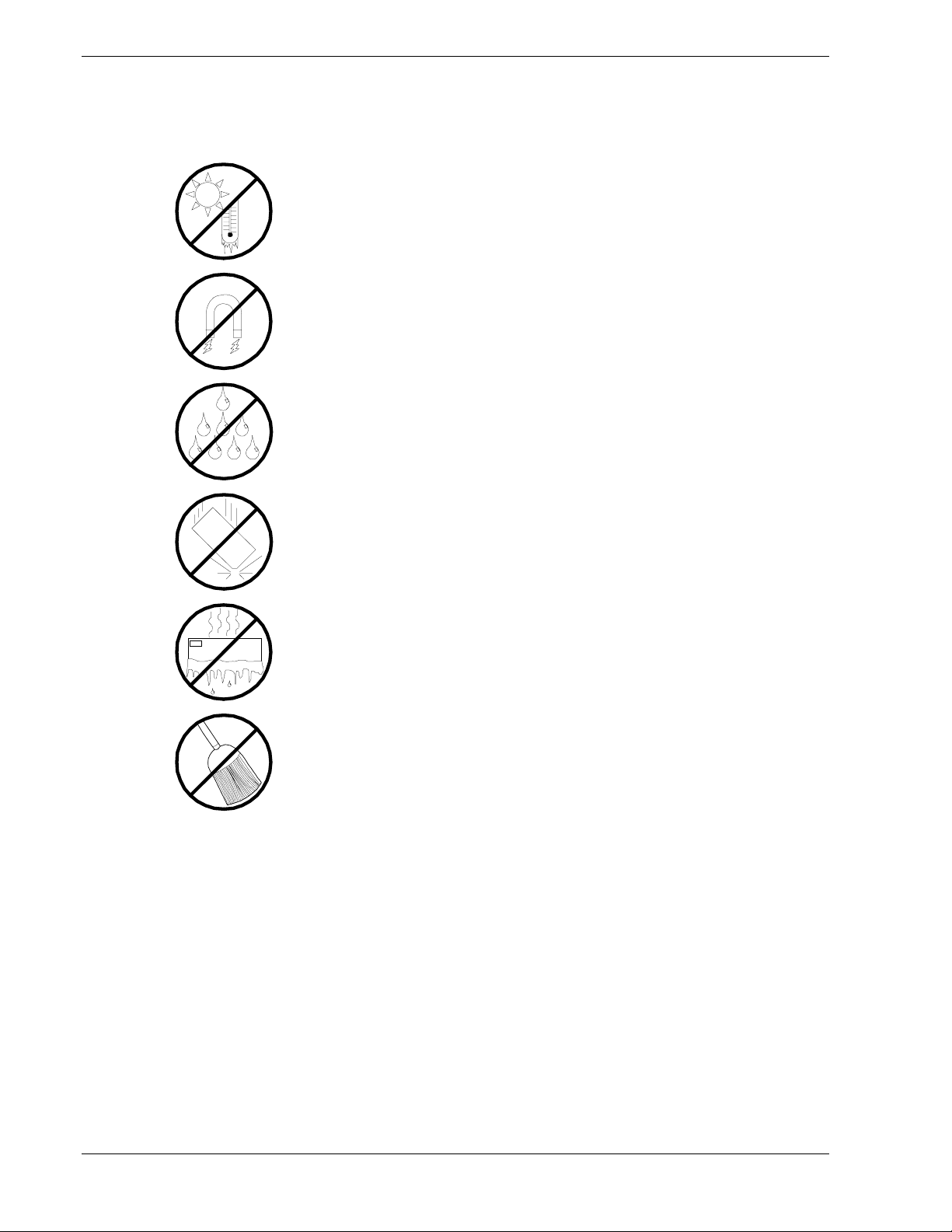
Care and Handling
Use the following guidelines to properly handle and care for your system.
Protect the system from extremely low or high temperatures. Let
the system warm (or cool) to room temperature before using it.
Keep the system away from magnetic forces.
Keep the system dry. Do not wash the system with a wet cloth or
pour fluid into it.
Protect the system from being bumped or dropped.
Check the system for condensation. If condensation exists, allow it
to evaporate before powering on the system.
Keep the system away from dust, sand, and dirt.
xiv Using This Guide
Page 17

System Overview
!
Overview
!
Chassis Feature summary
!
Chassis Front Controls and Indicators
!
Chassis Rear Controls and Features
!
Peripherals
!
Hot-swap Power Supplies
!
System Cooling
!
Boardset Description
!
Boardset Features
1
!
Processor Overview
!
Memory Overview
!
DIMM Installation Sequence
!
Peripheral Ports
!
Add-in Board Slots
!
Video
!
SCSI Controller
!
IDE Controller
!
Keyboard and Mouse
!
Remote Power-On (Wake On LAN) Function
!
System Security
!
Reconfiguration
Page 18
Overview
The E
accommodate the needs of a variety of high-performance applications—for example,
network servers, multi-user systems, and large database operations. As your application
requirements increase, you can upgrade your server with:
More powerful and/or additional processors
!
An additional processor mezzanine carrier with cache coherency filters
!
An additional memory module and additional memory
!
Add-in I/O boards
!
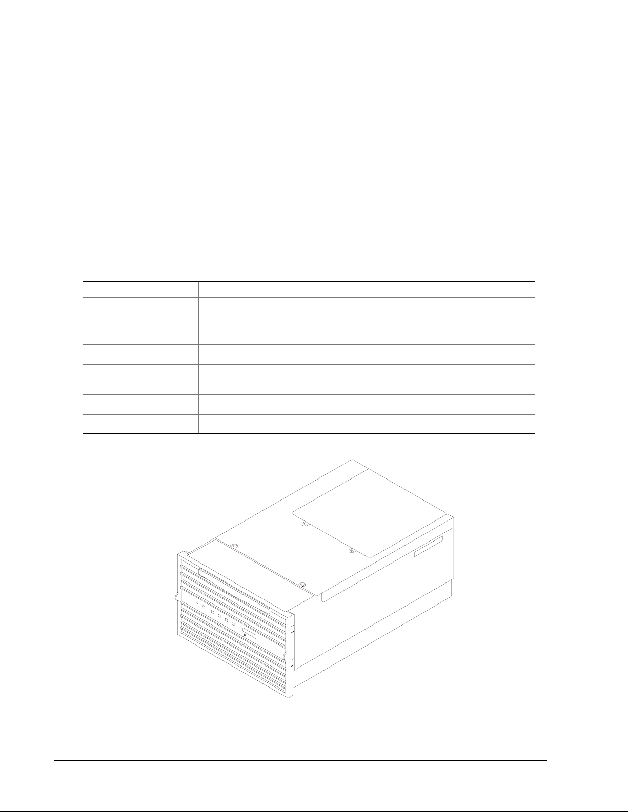
Table 1-1 lists the server physical specifications.
Specification Value
Height 31.12 cm (12.25 inches, 7u)
Width 44.45 cm (17.5 inches)
Depth 71.12 cm (28.0 inches)
XPRESS
5800/180Rb-7 server (see Figure 1-1) is easy to integrate and can easily
Table 1-1. Server Physical Specifications
Weight 51.4 kg (113 lbs) minimum configuration
60 kg (132 lbs) maximum configuration
Required front clearance 10 inches (inlet airflow <35 °C / 95 °F)
Required rear clearance 8 inches (no airflow restriction)
1-2 System Overview
Figure 1-1. E
XPRESS
5800/180Rb-7 Server
Page 19

Chassis Feature Summary
Table 1-2 contains a summary of the chassis features.
Table 1-2. Chassis Feature Summary
Feature Comment
Power system with redundancy The 750 watt, autoranging power supplies include integrated fans for
cooling. These power supplies operate at 100–120VAC or
200–240 VAC. When the server is configured with three supplies
(2 + 1), the third provides redundancy. The supplies can be replaced—
hot-swapped—without turning off server power. The server requires a
minimum of two power supplies. LEDs on the back of the power supply
indicate power on, failure, and predictive failure.
Server chassis The electrogalvanized metal used in manufacturing the server chassis
minimizes electromagnetic interference (EMI) and radio frequency
interference (RFI).
The peripheral bay provides the interface for 3.5- and 5.25-inch media.
It can support:
• One 5.25-inch IDE CD-ROM drive in the 5.25-inch half-height bay.
(Optional: any IDE or single-ended SCSI device, like a tape drive.)
• Two 3.5-inch wide by 1.0- or 1.6-inch hot-swappable low-voltage
differential SCSI (LVDS) hard disk drives mounted side-by-side in
the 3.5-inch hot-swapping bays. These bays allow hot-swapping of
hard disk drives without shutting down the server.
Ten hot-plug PCI I/O expansion slots.
The plastic front bezel provides airflow and easy access to drives in the
hot-swapping bays. The removable top covers provide proper airflow
and easy access to components inside the server. Only technically
qualified personnel should remove the server covers.
Cooling system with redundancy Six fans (5 + 1) cool and circulate air through the server. The sixth fan
is redundant. The fans can be replaced—hot-swapped—without
turning off server power. An LED indicator mounted next to each fan
guarantees positive identification of the failed fan.
Integrated power supply fans—two or three—cool and circulate air
through the power supplies and the bottom of the chassis.
Server management
Interintegrated circuit bus (I
communication. Interchassis management bus (ICMB) for interchassis
platform management communications.
Real-time clock/calendar (RTC).
Front panel controls and indicators (LEDs).
Basic Input/Output System (BIOS), Power-on Self Test (POST), and
Setup Utility stored in a flash memory device.
System Setup Utility (SSU).
Symbios SCSI Utility.
2
C) for diagnostic and intrachassis
Emergency Management Port (EMP) utility.
Field Replacement Unit (FRU) and Sensor Data Record (SDR) load
utility.
System Overview 1-3
Page 20
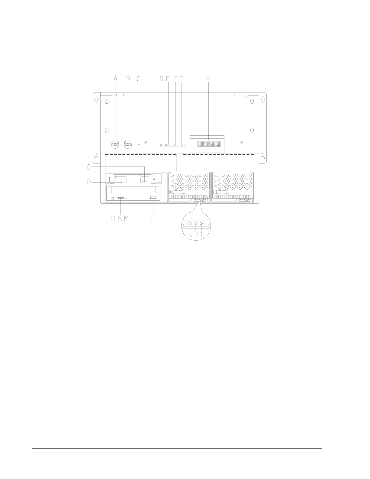
Chassis Front Controls and Indicators
Figure 1-2 shows the chassis front controls and indicators. Table 1-3 provides a
description of the chassis front controls and indicators.
Figure 1-2. Front Controls and Indicators
1-4 System Overview
Page 21

Table 1-3. Front Controls and Indicators
Item Feature Description
Front Panel
A Power switch When pressed, it turns on or off the server. The +5 V standby voltage
is ON whenever the server is plugged in.
B Reset switch When pressed, it resets the server and causes the power-on self test
(POST) to run.
C NMI switch When pressed, it causes a non-maskable interrupt. This switch is
recessed behind the front panel to prevent inadvertent activation. It
must be pressed with a narrow tool (not supplied).
D Power LED (green) When lit continuously, it indicates the presence of DC power in the
server. When not lit, it indicates power is turned off or power source is
disrupted.
E Power fault LED (yellow) When lit continuously, it indicates presence of DC power.
F Cooling fault LED (yellow) When flashing, it indicates a fan failure.
G Drive fault LED (yellow) When lit continuously, it indicates an asserted fault status on one or
more hard disk drives in the hot-swapping bay. When flashing, it
indicates drive reset in progress.
H Front panel LCD Displays information about processor type and failure codes.
Status LEDs for SCSI Drives in Hot-swapping Bays
I Drive power LED (green) When lit continuously, it indicates the presence of the drive and power
on the drive.
J Drive activity LED (green) Indicates drive activity.
K Drive fault LED (yellow) When lit continuously, it indicates an asserted fault status on one or
more hard disk drives in the hot-swapping bay. When flashing, it
indicates drive reset in progress.
Typical CD-ROM Drive
L Open/close button When pressed, it opens or closes the CD-ROM tray.
M Activity LED When lit, it indicates the drive is in use.
N Volume control It adjusts the volume of headphones or speakers.
O Headphone jack It provides a connection for headphones or speakers.
3.5-inch Diskette (Floppy) Drive
P Activity LED When lit, it indicates the drive is in use.
Q Ejector button When pressed, it ejects the diskette.
System Overview 1-5
Page 22
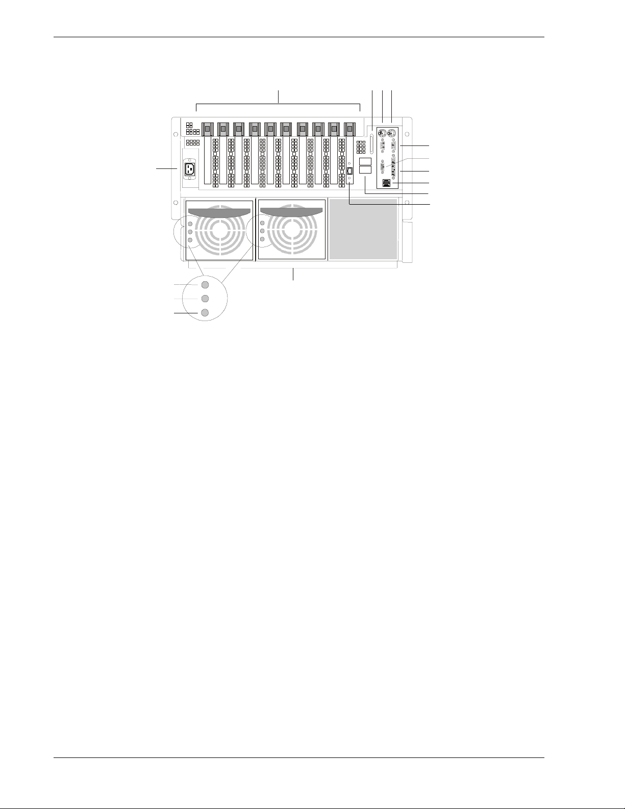
Chassis Rear Controls and Features
A CB
O
N
M
L
A. PCI add-in board expansion slots
B. External LVDS connector
C. PS/2-compatible keyboard/mouse port, 6-pin
D. PS/2-compatible keyboard/mouse port, 6-pin
E. PS/2-compatible serial ports A and B, 9-pin RS-232 connector
F. Super VGA compatible, 15-pin video connector
G. PS/2-compatible parallel port (LPT), 25-pin bidirectional subminiature D connector
H. USB ports 0 and 1, 4-pin connector
I. Interchassis Management Bus (ICMB) connectors port 1 and 2
J. PCI LAN controller board for 100Base-TX/10Base-TX Fast Ethernet networks with
RJ-45 Ethernet connector and status lamps.
Top lamp (ACT/LNK): Blinking (Green) – linked to network, sending or receiving data
Bottom lamp (100TX): ON (Orange) – 100 Mbps network connection
K. Power supplies (in this view, supplies must be populated from left to right; the right
bay would contain the redundant supply)
L. Power supply failure LED (yellow)
M. Power supply predictive failure LED (yellow) for power supply fan
N. Power supply power LED (green)
O. AC input power connector
K
OFF – not linked to network
OFF – 10 Mbps network mconnection
D
E
F
G
H
I
J
OM08781
1-6 System Overview
Figure 1-3. Chassis Rear View
Page 23

Peripherals
The peripheral bay provides the interface for 3.5-inch and 5.25-inch media.
3.5-inch Diskette Drive
The 3.5-inch diskette drive in the peripheral bay supports 720 KB and 1.44 MB media.
The drive is accessible from the front of the system and is located behind the front
panel.
3.5-inch Hard Drive Bays
The peripheral bay contains two hot-swapping bays for two 3.5-inch-wide (1.0-inch
high or 1.6-inch high) wide/fast-20 SCSI III SCA-type hard drives. The hard drives are
accessible at the front of the system behind a secure front panel and connect to a wide
LVDS hot-swap SCSI backplane.
As part of the hot-swap implementation, a drive carrier with an integral heatsink is
required. The drives are mounted in the carrier with four fasteners and the carrier snaps
into the chassis with a locking handle. A single metal EMI shield and plastic door
cover the drive bays. A hot-swapping bay is provided for drives that are 3.5 inches
wide and 1.0 or 1.6 inches high. Drives can consume up to 24 watts of power and must
be specified to run at a maximum ambient temperature of 40 ° C (104 °F).
5.25-inch Removable Media Device Bay
The peripheral bay has one 5.25-inch half-height bay that is accessible from the front of
the system. This bay includes a CD-ROM drive used for software installation.
Note:
the installation of a hard disk drive is not recommended. Hard disk
drives generate EMI (increasing ESD susceptibility), and this bay
does not provide adequate cooling for a hard disk drive.
The use of the 5.25-inch removable media device bay for
System Overview 1-7
Page 24

Hot-swap Power Supplies
The chassis can be configured with two or three 750-watt power supplies in a 2 + 1
redundancy configuration. If you have three supplies installed, you can hot-swap a
failed supply without affecting system functionality. If you have two supplies installed,
they must occupy the left and center bays (as you face the back of the server—see
Figure 1-3). Each supply is designed to minimize EMI and RFI. This system is
designed to operate at 100-120VAC or 200-240VAC.
The DC output voltages of each power supply are:
+3.3 V at 36.0 A max
!
+5 V at 36.0 A max (total combined output of +3.3 V and +5.5 V not to exceed
!
195 W)
+12 V at 36.0 A with 42.0 A <10ms peak
!
+24 V at 100 mA
!
-12 V at 1.0 A
!
+5 V standby 1.0 A
!
Each supply docks to a 36-pin connector on the system midplane.
System Cooling
The server contains two independent cooling subsystems:
The upper system, cooling the front panel, profusion carrier, and I/O carrier
!
(5 + 1 redundancy)
The lower system, cooling the memory modules, peripheral bay, and power supplies
!
(2 + 1 redundancy)
Both subsystems offer redundant cooling capabilities. As shipped from the factory, the
minimum configuration includes six system fans in the upper subsystem and two power
supplies (each has an integrated fan). You can install one additional power supply.
Note:
cooling.
All chassis covers must be on the system for proper
1-8 System Overview
Page 25

Boardset Description
The modular scaleable architecture of the rack server supports symmetrical
multiprocessing (SMP) and a variety of operating systems. The server comes with
Peripheral Component Interconnect (PCI) and Industry Standard Architecture (ISA)
buses. ISA buses are used internally only. The system has no ISA slots or a way for
the user to make use of the ISA bus. The server boardset consists of a set of printed
circuit boards:
Profusion carrier
!
Processor mezzanine board(s)
Front side bus (FSB) terminator modules
Cache coherency filters
PCI hot-plug (PHP) I/O carrier
!
Low-voltage differential SCSI (LVDS) hot-swap disk backplane
I/O riser board
Two memory modules
!
Front panel controller board
!
Midplane
!
The profusion carrier is mounted horizontally toward the front of the chassis, and the
PHP I/O carrier is mounted horizontally towards the rear of the chassis. The carriers
plug into connectors on the midplane mounted between the two carriers. The midplane
interconnects the carriers with the memory modules and power supplies. The front
panel board is mounted in front of the profusion carrier in the same plane. This board
provides the user interface, server management, cooling system control, and power
control.
System Overview 1-9
Page 26
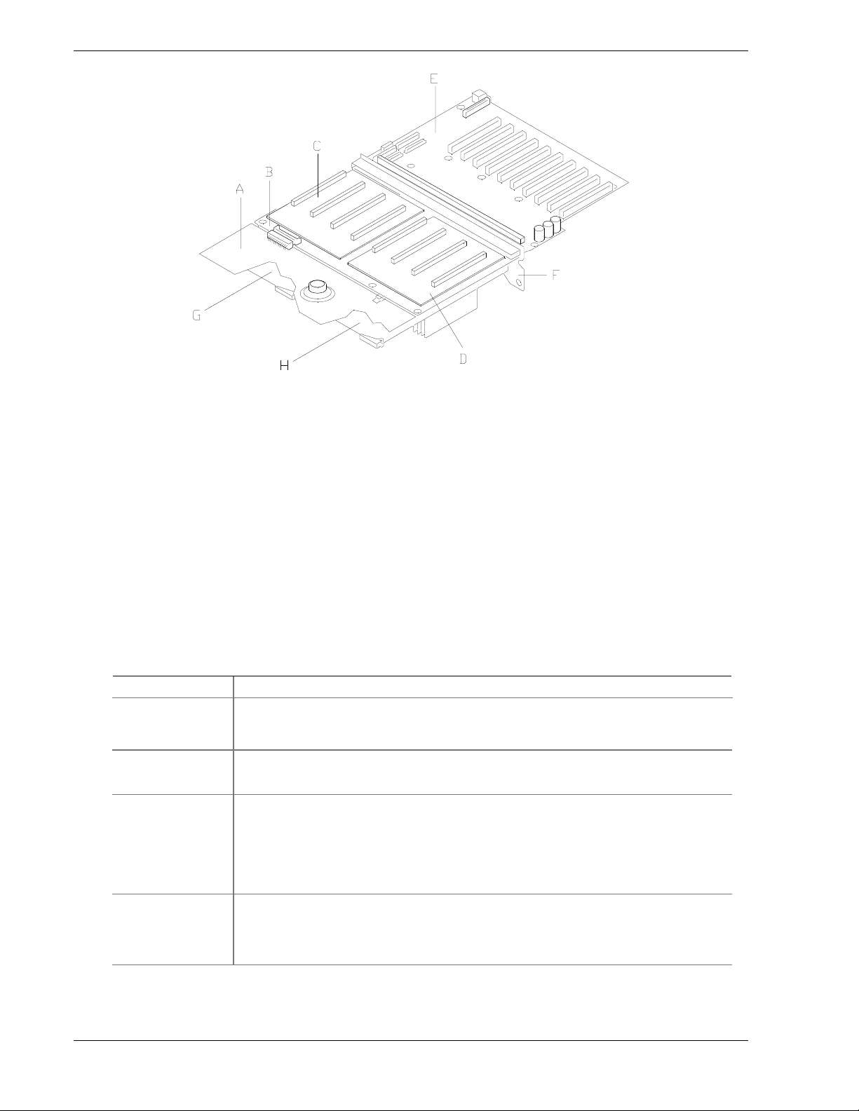
Figure 1-4. Boardset Overview
Boardset Features
Table 1-4 lists the boardset features.
Table 1-4. Boardset Features
Feature Description
Profusion carrier The profusion carrier provides the interface for processors (via one or two processor
mezzanine boards), memory modules, and cache coherency filters.
A. Front panel board
B. Profusion carrier
C. Processor mezzanine board 1
D. Processor mezzanine board 2
E. I/O carrier
F. Midplane
G. Memory module 1
H. Memory module 2
Processor
mezzanine boards
Pentium III Xeon
processor
packaged in an
S.E.C. cartridge
Memory modules Two dual plug-in modules containing interleaved pathway to main memory supporting
1-10 System Overview
The profusion carrier supports up to two processor mezzanine boards. Each
mezzanine board supports up to four Intel
Installed: Up to eight Pentium III Xeon processors, packaged in single edge contact
(S.E.C.) cartridges and installed in 330-pin Slot 2 processor connectors, operating at
1.8 V to 3.5 V. The profusion carrier provides connectors for two processor
mezzanine boards. Each mezzanine board provides four Slot 2 connectors. The
carrier's voltage regulator is automatically programmed by the processor's VID pins to
provide the required voltage.
PC100 registered SDRAM. Each memory module supports from 128 MB to 16 GB of
error correction code (ECC) memory using sixteen 72-bit dual inline memory modules
(DIMMs). The modules interface to the profusion carrier through the midplane.
®
Pentium® III Xeon™ processors.
(continued)
Page 27

Boardset Features (continued)
Feature Description
FSB terminator
module
This module plugs into any unpopulated Slot 2 connector on either processor
mezzanine board. The module terminates the FSB GTL+ signals of the
Slot 2 connector when a processor S.E.C. cartridge is not installed in a connector.
Cache coherency
filters
PHP I/O carrier Ten hot-pluggable 64-bit PCI expansion slots (six at 33 MHz, four at 66 MHz).
I/O riser board This board contains all legacy I/O connections; it plugs into an edge connector on the
The cache coherency filters contain information on each of the two processor buses,
thus enabling each bus to perform with minimal snoop cycles. The profusion carrier
requires that these filters be populated if the server has two processor mezzanine
boards that are both populated with processors.
Integrated Cirrus Logic† GD5446 VisualMedia† PCI super video graphics array
(SVGA) controller with 2 MB of video memory.
The Symbios 53C896 LVDS SCSI controller supports two LVDS channels. One
channel is used internally to provide support for the internal SCSI drives (connected to
the LVDS hot-swap disk backplane) and CD-ROM or tape drive. The second LVDS
channel is routed to the rear of the chassis to support external devices.
The diskette controller supports one drive.
The PCI-enhanced Integrated Drive Electronics (IDE) interface supports one IDE bus.
PS/2-compatible keyboard/mouse controller.
Two universal serial bus (USB) ports.
PHP I/O carrier.
PS/2-compatible keyboard and mouse ports (interchangeable).
PS/2-compatible parallel port.
Analog VGA, 15-pin video port.
Two PS/2-compatible, 9-pin serial ports.
LVDS hot-swap
disk backplane
Front panel board The front panel board provides the user interface to the server. The board allows
Midplane The midplane:
This backplane supports hot-swapping of up to two SCA2-type SCSI drives, mounted
in carriers, in and out of the hot-swapping bays.
other servers to communicate with this server, even while power is down, via an
Interchassis Management Bus (ICMB).
Push-button switches control power-up, reset, and nonmaskable interrupt
(NMI) functions.
LEDs indicate power on, power supply failure, hard drive failure, or a fan or other
server cooling failure.
An LCD panel provides information about boot status, available number of processors,
and other server management information.
• Electrically connects the PHP I/O and profusion carriers
• Contains the sockets for the memory modules
• Distributes DC power to the PHP I/O and profusion carrier, disk backplane, cooling
fans, memory boards, and front panel board
• Distributes the power load of the server among two or three 750-watt autoranging
power supplies
System Overview 1-11
Page 28

Processor Overview
Each Intel Pentium III Xeon processor is packaged in a single edge contact (S.E.C.)
cartridge. The cartridge includes:
The processor core with an integrated 32 KB primary (L1) cache
!
The secondary (L2) cache
!
A thermal plate
!
A back cover
!
Each processor implements the MMX™ technology with streaming SMID extensions
and maintains full backward compatibility with the 8086, 80286, Intel386™,
Intel486™, Pentium, and Pentium Pro processors. The processor's numeric coprocessor
significantly increases the speed of floating-point operations and complies with
ANSI/IEEE standard 754-1985.
Each S.E.C. cartridge connects to one of two processor mezzanine boards through a
330-pin Slot 2 edge connector (SC330.1). The cartridge is secured to the mezzanine
carrier by a retention mechanism. Each mezzanine board connects to the profusion
carrier. Depending on configuration, your system has one to eight processors.
The processor external interface is multiprocessor (MP)-ready and operates at 100
MHz. The processor contains a local APIC unit for interrupt handling in MP and
uniprocessor (UP) environments.
The L2 cache is located on the same die as the processor core and L1 cache. The cache:
Is offered in 1 MB and 2 MB configurations
!
Is ECC protected
!
Operates at the full core clock rate
!
Memory Overview
Main memory resides on two add-in boards, called memory modules. Each memory
module contains slots for 16 DIMMs and is attached to the profusion carrier through a
300-pin connector on the midplane. The memory controller supports PC 100-registered
SDRAM DIMMs. Various DIMM sizes are supported, but each DIMM must be at least
128 MB. Memory amounts from 128 MB to 16 GB per module are supported. The
ECC used for the memory module is capable of correcting single-bit errors (SBEs) and
detecting 100% of double-bit errors over one code word. Nibble error detection is also
provided.
You can install:
From 1 to 32 DIMMs (total number of DIMMs for two memory modules)
!
Equal number of DIMMs on each memory module (except when only one DIMM is
!
used)
1-12 System Overview
Page 29

Note:
sizes on that module may vary, but when both memory modules are
installed, the DIMM configuration on the two modules should be
identical to support memory interleaving for performance gains.
When only a single memory module is installed, DIMM
Depending on how the memory modules are installed, the memory subsystem can
operate in two different modes: interleaved and single-port.
Interleaved mode (two memory modules installed): The memory modules share a
!
common address range. One memory module responds to even-numbered cache
lines, while the other responds to odd-numbered cache lines. This configuration
offers the highest performance because it allows the two modules to be used in a
balanced fashion, reducing address conflicts. To operate in interleaved mode, the
DIMMs must be installed in pairs (one on each module) and in the same locations
on each module.
Single port mode (one memory module installed): The single memory module
!
responds to all memory addresses. The DIMMs on this single carrier need not be
installed in pairs and can be installed one DIMM at a time.
DIMM Installation Sequence
A single carrier will support DIMM population in various configurations (empty
sockets included). However, when fewer than 16 DIMMs are installed on a memory
module, the preferred population order is to start from the lowest J number and populate
sequentially to the highest. This recommendation helps maintain optimal signal
integrity and thermal performance.
Note:
module installed. This increases to 32 GB with two modules.
Maximum capacity is limited to 16 GB with one memory
Some OSs and application programs use base memory while others use both
conventional and extended memory. Examples:
Base memory: MS-DOS, OS/2, Windows NT, and UNIX
!
Conventional and extended memory: OS/2, Windows NT, and UNIX
!
MS-DOS does not use extended memory; however, some MS-DOS utility programs
like RAM disks, disk caches, print spoolers, and windowing environments use extended
memory for better performance.
BIOS automatically detects, sizes, and initializes the memory array, depending on the
type, size, and speed of the installed DIMMs, and reports memory size and allocation to
the system via configuration registers.
Note:
been tested for compatibility. Contact your sales representative or
dealer for a list of approved DIMMs.
DIMM sizes and compatibility: Use DIMMs that have
System Overview 1-13
Page 30

Peripheral Ports
Super I/O Chip
The 37C937 Super I/O device supports two serial ports, one parallel port, diskette drive,
and PS/2-compatible keyboard and mouse. The system provides the connector interface
for each port.
Serial Ports
Both serial ports are relocatable. By default, port A is physically the left connector (as
you look at the back of the system — see Figure 1-3. Chassis Rear View), port B the
right connector. Each serial port can be set to one of four different COMx ports, and
each can be enabled separately. When enabled, each port can be programmed to
generate edge- or level-sensitive interrupts. When disabled, serial port interrupts are
available to add-in boards.
Parallel Port
The 25/15-pin connector stacks the parallel port over the VGA. The 37C937 provides
one IEEE 1284-compatible 25-pin bi-directional EPP (supporting levels 1.7 and 1.9).
BIOS programming of the Super I/O registers enables the parallel port and determines
the port address and interrupt. When disabled, the interrupt is available to add-in
boards.
Add-in Board Slots
The I/O carrier has ten 64-bit PCI buses (nine available) contained in four PCI
segments. PCI slot 10 contains the system LAN controller board.
PCI-A provides for PCI slots 1 and 2 (33 MHz), dual-channel LVDS SCSI
!
controller, video, and PIIX4E.
The PIIX4E controls communications to IDE, onboard ISA, USB, and Super I/O
for handling the keyboard, mouse, diskette drive, parallel port, and serial ports.
PCI-B provides for PCI slots 3 through 6 (33 MHz).
!
PCI-C provides for slots 7 and 8 (two of the 66 MHz, 3.3 V slots).
!
PCI-D provides for slots 9 and 10 (the two other 66 MHz, 3.3 V slots).
!
Video
The onboard, integrated Cirrus Logic CL-GD5446 64-bit VGA chip contains an SVGA
controller that is fully compatible with these video standards: CGA, EGA, Hercules
Graphics, MDA, and VGA. The standard system configuration comes with 2 MB of 10
ns onboard video memory. The video controller supports pixel resolutions of up to
1600 x 1200 and up to 16.7 M colors.
†
1-14 System Overview
Page 31

The SVGA controller supports analog VGA monitors (single and multiple frequency,
interlaced and noninterlaced) with a maximum vertical retrace noninterlaced frequency
of 100 Hz.
You can not add video memory to this system. Depending on the environment, the
controller displays up to 16.7 M colors in some video resolutions. It also provides
hardware-accelerated bit block transfers (BITBLT) of data.
SCSI Controller
A Symbios 53C896 Ultra2 SCSI chip provides two 16-bit high-speed SCSI channels.
This high-performance SCSI controller is capable of providing data rates up to 80
MB/sec per channel in 16-bit operations to ensure maximum data throughput while
minimizing PCI bus overhead.
Each channel is capable of operations using either 8- or 16-bit SCSI providing
10 MB/sec (Fast-10) or 20 MB/sec (Fast-20) throughput, or 20 MB/sec (Ultra),
40 MB/sec (Ultra-wide), or 80 MB/sec (40 MHz) (Ultra-2).
The SYM53C896 has its own set of PCI configuration registers and SCSI I/O registers.
As a PCI 2.1 bus master, the controller supports burst data transfers on PCI up to the
maximum rate of 132 MB/sec using on-chip buffers.
In the hot-swap SCSI hard drive bay, the system supports up to two 1-inch SCSI hard
disk drives. The 5.25-inch removable media bay supports one SCSI or IDE device (the
controller itself supports more devices, but the 5.25-inch bay can contain a maximum of
one device). SCSI devices do not need to operate at the ultra transfer rate. All drives
on the bus must be Ultra-2 (LVD) to run at 80MB/sec (40Mhz). The 5, 10, and 20
MHz operations can coexist on the bus, and each device will interact at its appropriate
speed.
No logic, termination, or resistor loads are required to connect devices to the SCSI
controller other than termination in the device at the end of the cable. The SCSI bus is
terminated on the I/O carrier with active terminators.
IDE Controller
IDE is a 16-bit interface for intelligent disk drives with AT† disk controller electronics
onboard. The PCI/ISA/IDE Accelerator, called PIIX4E, is a multifunction device on
the I/O carrier that acts as a PCI-based Fast IDE controller. The device controls:
PIO and IDE DMA/bus master operations
!
Mode 4 timings
!
Transfer rates up to 22 MB/sec (33 MB/sec using ultra DMA transfers)
!
Buffering for PCI/IDE burst transfers
!
Master/slave IDE mode
!
System Overview 1-15
Page 32

Keyboard and Mouse
The PS/2 compatible keyboard and mouse connectors are mounted in a single-stacked
housing with the mouse connector over the keyboard. External to the system, they
appear as two connectors.
The user can plug in the keyboard and mouse to either connector before powering up
the system. BIOS detects these and configures the keyboard controller accordingly.
The keyboard controller is functionally compatible with the 8042A microcontroller.
The system can be locked automatically if no keyboard or mouse activity occurs for a
predefined length of time, if specified through the SSU (see security options in
“Security Add-in). Once the inactivity (lockout) timer has expired, the keyboard and
mouse do not respond until the previously stored password is entered.
Remote Power-On (Wake On LAN) Function
The remote power-on (Wake On LAN) function turns on the system power by way of
the network. If the system power is set to Off, it can be turned on remotely by sending a
specific packet from the main computer to the remote system.
System Security
To help prevent unauthorized entry or use of the system, the system includes a full
lockable front cover and internal software locks via the BIOS setup utility and system
setup utility (SSU).
Security with Mechanical Lock
The front cover of the server contains a mechanical lock to prevent access to the front
of the computer chassis.
Software Locks
The BIOS Setup Utility and System Setup Utility (SSU) provide a number of security
features to prevent unauthorized or accidental access to the system, as follows.
Security with BIOS Setup:
Set server administrative and user passwords.
!
Set secure mode to prevent keyboard or mouse input and to prevent use of the front
!
panel controls.
For more information, see “Security Add In” in Chapter 3.
!
1-16 System Overview
Page 33

Security with the System Setup Utility (SSU):
Enable the keyboard lockout timer so that the server requires a password to
!
reactivate the keyboard and mouse after a specified time-out period of 1 to 128
minutes.
Set an administrative password.
!
Set a user password.
!
Activate the secure mode hot-key.
!
Disable writing to the diskette drive.
!
For more information, see “Security Add In”in Chapter 3,
!
Password Protection
BIOS passwords prevent unauthorized tampering with the server. If you set the user
password, but not the administrative password, BIOS requires you to enter the user
password before you can boot the server or run the SSU. If you set both passwords,
entering either password lets you boot the server or enable the keyboard and mouse.
Only the administrative password lets you change the server configuration with the
flash-resident Setup utility.
Secure Boot Mode
Secure boot mode allows the server to boot and run the OS. However, you cannot use
the keyboard or the mouse until you enter the user password.
You can use Setup to put the server in secure boot mode. If BIOS detects a disk in the
CD-ROM drive or a diskette in floppy drive A at boot time, it prompts you for a
password. When you enter the password, the server boots from the disk in the CDROM drive or the diskette in drive A. Entering a password also disables secure mode.
If there is no disk in the CD-ROM drive or diskette in drive A, the server boots from
drive C and automatically goes into secure mode. All enabled secure mode features go
into effect at boot time.
If you set a hot-key combination, you can secure the server immediately.
Boot Sequence Control
The BIOS security features determine the boot devices and the boot sequence. They
also control disabling writes to the diskette drive in secure mode. You can use the SSU
or Setup to select each boot device. The default boot sequence is diskette, hard disk,
CD-ROM, and network.
Boot Without Keyboard
The server can boot with or without a keyboard. Before it boots, BIOS displays a
message keyboard detection. During POST, BIOS automatically detects and tests the
keyboard if one is present.
System Overview 1-17
Page 34

Locked Power and Reset Switches
The power and reset push-button switches on the front panel are locked when the server
is in secure mode. To exit from the secure mode, you must enter your user password.
Diskette Write Protect
If Diskette Write Protect is enabled in Setup, it write-protects the diskette drive only
while the server is in the secure mode. To exit secure mode, enter your user password.
Video Blanking
If Video Blanking is enabled in Setup, the video display will be off when the server is
in secure mode. To exit secure mode, enter your user password.
Reconfiguration
If a CPU or a memory DIMM board error was detected during execution of POST
(Power On Self-Test) after system power is turned on, the reconfiguration function
isolates the failed CPU or memory DIMM board and continues operation. You should
replace the failed device as soon as possible.
This function is enabled only when the following system requirements are met:
Two or more CPUs are installed.
!
Eight memory DIMM boards are installed.
!
A CPU or memory DIMM board error may be viewed on the screen while POST is
running or by entering BIOS Setup. It may also be viewed when the ESMPRO Suite
program is installed and operating.
1-18 System Overview
Page 35

Setting Up the System
!
Overview
!
Selecting a Site
!
Unpacking the System
!
Rack-Mount Subsystem Assembly
!
Getting Familiar with the System
!
Making Connections
!
Connecting the Power Cord
!
Using the System
2
Page 36

Overview
This chapter describes how to select a site, unpack the system, make cable
connections, and power on the rack-mount system units. Also, provided are the
instructions for assembling the rack-mount system units.
Selecting a Site
The system operates reliably in a typical office environment.
Choose a site that is:
Near grounded, three-pronged power outlets.
!
Note
: For the United States and Canada, this means
NEMA 5-15R outlets for 100-120VAC and NEMA 6-15R
outlets for 200-240 VAC. For other international sites, this
means three-pronged power outlets applicable for the
electrical code of the region.
Be sure the power service connection is through a properly
grounded outlet.
!
WARNING
Clean, dust-free, and well ventilated. Front and rear ventilating openings
!
kept free of obstructions. Away from sources of heat, vibration or
physical shock.
Isolated from strong electromagnetic fields and electrical noise produced
!
by electrical devices (such as air conditioners, large fans, large electric
motors, radio and TV transmitters, and high-frequency security devices)
Spacious enough to provide at least five inches (13 centimeters) behind
!
the system and three inches (eight centimeters) on each side of the system
for proper cooling, airflow, and cable clearance.
Easily accessible for system maintenance and installation of system
!
upgrades.
2-2 Setting Up the System
Page 37

Unpacking the System
!
WARNING
Your rack-mount server weighs approximately 113 pounds
(51 kg). If your server contains numerous optional boards
and peripheral devices, it will weigh more. To avoid personal
injury, make sure you use only a mechanical assist unit to lift
it off the shipping pallet. The minimum server configuration
weighs 51 kg (113 lbs); the maximum weighs 63.5 kg
(140 lbs). Use only a hand-truck or other mechanical assist
unit to move the server from one location to another.
When you receive your system if the shipping boxes are damaged, note the
damage, and if possible, photograph it for reference. After removing the
contents of the containers, keep the cartons and the packing materials. If the
contents appear damaged when you unpack the boxes, file a damage claim with
the carrier immediately.
Setting Up the System 2-3
Page 38

Rack-Mount Subsystem Assembly
M
This section provides the instructions for assembling the rack-mount server into
a standard EIA 19-inch rack cabinet.
Unpacking the Rack Mounting Hardware
Although the rack mounting hardware is inspected and carefully packaged at the
factory, damage may occur during shipping. Follow these steps for unpacking.
1. Visually inspect the shipping containers; notify your carrier immediately of
any damage.
2. Carefully remove the rack mounting hardware and verify the parts. See
Figure 2-1 and Table 2-1. If parts are missing or the hardware is damaged,
notify your server representative.
D
H
A
E
I
B
F
J
G
K
L
C
N O
P
Figure 2-1. Rack Mounting Hardware
2-4 Setting Up the System
Page 39

Table 2-1. Rack Mount Parts
Reference Description Reference Description
A Slide Rail Assembly (Left Side) I Arm Bracket 2
B Slide Rail Assembly (Right Side) J Arm Bracket 3
C Cable Retention Arm K Template
D Arm Plate A
Fits APC
E Arm Plate B
Fits Dell Rack Cabinet
F Arm Plate C
Fits Compaq Rack Cabinet
G Arm Plate D
Fits Rittal Rack Cabinet
H Arm Bracket 1 P Washers (8) for Large M5 Screws
Before You Begin
Before you begin, please review the following cautions, warnings, and general
guidelines.
Be sure that power to the system is turned off and
unplugged. All voltage is removed only when the power
cords are unplugged.
Rack Cabinet
!
WARNING
L Tie Wraps (20)
M Small 6-32 Screws (8)
N Large M5 Screws (10)
O Small 6-32 Flat Head Screws (6)
Avoid excessive vibration and shock. Dropping an electronic component
!
can cause serious damage.
Do not disconnect or remove parts other than those specified in the
!
procedure.
Do not touch I/O connector pins.
!
All screws are Phillips-head, unless otherwise specified.
!
On completion of any assembly or reassembly, perform a power-on test.
!
If a fault occurs, verify that the assembly or reassembly was performed
correctly. If the problem persists, see "Problem Solving" in Chapter 5.
Static Precautions
An electrostatic discharge (ESD) can damage disk drives, option boards, and
other components. You can provide some ESD protection by wearing an
antistatic wrist strap attached to chassis ground when handling system
components.
Setting Up the System 2-5
Page 40

Electronic devices can be easily damaged by static electricity. To prevent
damage, keep them in their protective packaging when they are not installed in
your system.
Assembly
The following subsection describes how to assemble your rack-mount server
into a standard EIA 19-inch rack cabinet.
Before you begin select an appropriate location in your rack cabinet for the
rack-mount server. To improve rack stability, mount heavier items towards the
bottom of the rack cabinet. If the rack is a stand-alone unit and the rack is more
than 75% filled with components, consider installing an optional stabilizer kit.
Note:
rack cabinet you should consider the length of the cables
that interconnect system components.
A
NCHOR THE EQUIPMENT RACK
anchored to an unmovable support to prevent it from falling
over when one or more servers are extended in front of it on
slide assemblies. The anchors must be able to withstand a
force of up to 113 kg (250 lbs). You must also consider the
weight of any other device installed in the rack.
M
AIN
installing an AC power disconnect for the entire rack unit.
This main disconnect must be readily accessible, and it must
be labeled as controlling power to the entire unit, not just to
the server(s).
G
ROUNDING THE RACK INSTALLATION
an electrical shock hazard, you must include a third wire
safety grounding conductor with the rack installation. If a
server power cord is plugged into an AC outlet that is part of
the rack, then you must provide proper grounding for the
rack itself. If server power cords are plugged into wall AC
outlets, the safety grounding conductor in each power cord
provides proper grounding only for the server. You must
provide additional, proper grounding for the rack and other
devices installed in it.
When planning your system configuration for the
!
WARNING
: The equipment rack must be
AC
POWER DISCONNECT
: You are responsible for
: To avoid the potential for
2-6 Setting Up the System
Page 41

!
CAUTION
Temperature: The operating temperature of the server,
when installed in an equipment rack, must not go below 5 °C
(41 °F) or rise above 35 °C (95 °F). Extreme fluctuations in
temperature can cause a variety of problems in your server.
Ventilation: The equipment rack must provide sufficient
airflow to the front of the server to maintain proper cooling.
It must also include ventilation sufficient to exhaust a
maximum of 4,100 Btu's per hour for the server. The rack
selected and the ventilation provided must be suitable to the
environment in which the server will be used.
The template supplied with your rack mount kit defines the location of the
mounting screws in the system rack where the server is to be installed (see
Figure 2-2). The template can be placed on the front and rear of the rack cabinet
to show the mounting screw hole positions of the server guide rail assemblies,
front faceplate screws, and cable retention arm plate.
Note:
that the mounting screw hole cut outs are at the same height
on each side of the cabinet and level with each other.
The front of the template defines the front rail mounting
screw holes and front faceplate screws holes of the server in
the rack cabinet. The back of the template defines the rear
rail mounting screw holes of the server in a rack cabinet.
The back of the template also defines the screw holes for
the cable retention arm plate of the server in a rack cabinet.
Ensure that the template is aligned properly so
Front View Rear View
Figure 2-2. Template
Setting Up the System 2-7
Page 42

Use the following procedure to mark the front and rear screw hole locations of
the server in the rack cabinet.
1. Determine where you want to install the server in the rack cabinet.
To improve rack stability, mount the server towards the bottom of the
!
rack cabinet.
If there are units already installed, install the server into the next empty
!
space from the bottom of the rack cabinet.
2. Use the template supplied with your rack mount kit to mark the front and
rear mounting screw hole locations (with a pencil) where you want the
server to be mounted for the Rack Mounting Rail Assemblies, front bezel
thumbscrews holes, and Cable Retention Arm Plate. See Figure 2-3 for the
front vertical mounting rail and Figure 2-4 for the rear vertical mounting
rails.
Note:
the rack vertical mounting rail are equal to 1U (1.75 inches).
Mounting holes in the vertical rails of equipment racks are
commonly spaced in a 5/8 x 5/8 x 1/2-inch sequence.
Perform the following steps carefully; brackets must be
mounted with precision to allow room for the next server you
install in a rack.
For vertical reference, every three screw holes on
A – M5 Cagenuts for Server Faceplate
B – Rack Mounting Rail Assembly
Alignment Tabs
C – Rack Mounting Rail Assembly
M5 Screw Holes
Figure 2-3. Locating and Marking the Front Mounting Holes for the Server
2-8 Setting Up the System
Page 43

A
– M5 Cagenuts for Cable Retention Arm
B
– Rack Mounting Rail Assembly
Alignment Tabs
C
– Rack Mounting Rail Assembly
M5 Screw Holes
Figure 2-4. Locating and Marking the Rear Mounting Holes for the Server
3. While marking the hole locations for the Rack Mounting Rail Assemblies,
also mark the locations on the front vertical mounting rails for the cage nuts,
which hold the screws of the server faceplate (see Figure 2-3) and the Cable
Retention Arm (see Figure 2-4).
4. Insert four M5 cage nuts in their marked locations on the front vertical
mounting rails (see Figure 2-5), as follows:
Position the cage nut on the inside of the front vertical mounting rails.
!
Hook the side lip of a cage nut into the square hole in the rail.
!
Push the other side lip of the cage nut into the square hole in the rail
!
until it is secured.
Repeat for each cage nut.
!
Setting Up the System 2-9
Page 44

Figure 2-5. Inserting the Cage Nuts for the Server Faceplate
Attaching the Cable Retention Arm
The triple-hinged cable retention arm attaches to the rear of the server and the
rack cabinet allowing cables to swing in and out of the way as the server slides
back and forth within the rack cabinet (see Figure 2-6). All the server cables can
be tie-wrapped to the cable retention arm.
Note:
install the cable retention arm on the rear of the server
before mounting the server into the rack cabinet.
2-10 Setting Up the System
For easy installation of the cable retention arm,
Figure 2-6. Cable Retention Arm
Page 45

1. Remove the power supply located on the rear of the server directly under the
AC input power connector. Refer to “Removing a Power Supply” in
chapter 4.
2. Attach arm bracket 1 (see Figure 2-7, A) by placing it over the three screw
posts that protrude out on the inside edge of the chassis facing the power
supplies.
A
Figure 2-7. Attaching Arm Bracket 1 to the Rear of Server
3. Using three 6-32 screws secure arm bracket 2 (see Figure 2-8, A) to the
outside edge of arm bracket 1 just installed on the rear of the server. The rear
edge of the metal cabinet should now be sandwiched in between Arm
Bracket 1 (A) and Arm Bracket 2 (B)providing extra structural strength (see
Figure 2-9).
A
Figure 2-8. Attaching Arm Bracket 2
Setting Up the System 2-11
Page 46

B
Figure 2-9. Arm Bracket 1 and Arm Bracket 2 Assembled
A
4. Attach arm bracket 3 (see Figure 2-10, A) by placing it over the top screw
post that protrudes out on the inside edge of the chassis facing the power
supplies and secure with a 6-32 screw.
A
Figure 2-10. Attaching Arm Bracket 3
5. Using two screws attach one end of the cable retention arm to arm bracket 1
installed on the rear of the server (see Figure 2-11).
2-12 Setting Up the System
Page 47

Figure 2-11. Attaching the Cable Retention Arm to the Server
6. Reinstall the power supply removed in step 1.
7. Using two M5 screws attach one of the arm plates to the cage nuts in the
left-rear vertical-mounting rail of your rack cabinet (see Figure 2-12). There
are four arm plates (A, B, C, and D) available to fit the different types of
rack cabinets (see Figure 2-1 and Table 2-1).
Figure 2-12. Attaching the Arm Plate to the Rack Cabinet
Setting Up the System 2-13
Page 48

Installing the Slide Rail Brackets into the Rack Cabinet
Before you can mount the server in the rack cabinet, you must install the slide
rail into the rack cabinet.
Note:
the rack cabinet before mounting the server into it. Observe
all safety precautions, warnings, and cautions noted
throughout this chapter.
You must use the following procedure to prepare
Use the following procedure to install the slide rail into the rack cabinet.
Note:
the rack vertical mounting rail are equal to 1U (1.75 inches).
For vertical reference, every three screw holes on
1. Remove the slide rails and mounting screws from the rack-mount kit.
2. Align one of the slide rail assemblies behind the mounting holes in the
vertical mounting rail (see Figure 2-13) located on the right side of the rack
cabinet. The tabs on the front and rear of the slide rail assembly help to align
it with the holes previously marked in the vertical-mounting rail.
3. Install two M5 screws and two washers that secure the front of the slide rail
assembly to the front vertical-mounting rail and tighten loosely. See Figure
2-13).
Correct
Incorrect
A. Screw and washer
B. Vertical rail
Figure 2-13. Mounting a Slide Rail
4. Carefully align the rear holes of the slide rail assembly with the holes
previously marked in the rear vertical-mounting rail.
5. Install two M5 screws and two washers that secure the rear of the slide rail
assembly to the vertical-mounting rail.
6. Tighten all four screws holding the slide rail assembly to the vertical
mounting rails.
7. Repeat steps 2 through 6 for the mounting the other slide rail assembly on
the left side of the rack cabinet.
2-14 Setting Up the System
A
D
C
B
C. Slide rail
D. Server mounting tab
Page 49

Mounting the Server into the Rack Cabinet
Use the following procedure to mount the server into the rack cabinet (see
Figure 2-14).
!
WARNING
Anchor the Rack Cabinet. The rack cabinet must be
anchored to an unmovable support or a front stabilizer to
prevent it from falling over when one or more units are
extended in front of it on slide assemblies. The anchors
must be able to withstand a force of up to 113 kg (250
lbs.). You must also consider the weight of any other
device installed in the rack.
VOID INJURY
A
the server, use only a mechanical assist unit to lift it off the
shipping pallet. The minimum server configuration weighs
51 kg (113 lbs); the maximum weighs 63.5 kg (140 lbs).
Use only a hand-truck or other mechanical assist unit to
move the server from one location to another.
. To avoid personal injury when unpacking
1. Pull the two extension rails (see Figure 2-14, A) out of each rack mounting
assembly on the rack cabinet until they lock in place.
2. Use a mechanical assist unit or a minimum of four persons to carefully pick
up the server and place it onto the slide rails. Ensure the tabs on the slide rail
(see Figure 2-13, D) align with the slots in the system chassis.
3. Install three flat head screws on each side of the server to secure it to the
extension rails. See Figure 2-14.
A. Extension Rails
A
Figure 2-14. Installing the Server in the Rack
Setting Up the System 2-15
Page 50

4. Carefully press in on the safety latches (Figure 2-15, A) and slide the server
all the way into the rack cabinet.
Note: When you first slide the server into the rack
cabinet, extra pressure may have to be applied. After the
first time, the slides will move easier.
5. Check that the server slides in and out of the rack cabinet. Grasp the two
handles on the front of the server and slowly pull the server out and push it
back in.
A
Figure 2-15 Sliding the Server into the Rack
6. Using two 6-32 screws attach the other end of the cable retention arm to the
metal mounting bracket installed on the left rear vertical mounting rail (see
Figure 2-16).
Figure 2-16. Attaching the Cable Retention Arm to the Rack Cabinet
2-16 Setting Up the System
Page 51

7. Swing the cable retention arm back and forth a few times to ensure proper
movement of the arm (see Figure 2-17).
Figure 2-17. Swinging the Cable Retention Arm
8. Bundle all the server cables together and tie-wrap them to the cable retention
arm (see Figure 2-18).
Figure 2-18. Attaching the Cable Retention Arm
Setting Up the System 2-17
Page 52

Getting Familiar with the System
Before setting up your system, see System Overview in Chapter 1 of this User's
Guide to become familiar with the system’s features, such as the location of
your system's front and rear panel switches, indicators and connectors, etc.
Making Connections
If your system normally operates without a video display or keyboard (for
example, as a network server), you must install a video display and keyboard to
configure the system. You may remove them after running the BIOS Setup
Utility. For information on running the BIOS Setup Utility, refer to Chapter 3
Configuring Your System of this User’s Guide.
Connect your keyboard, monitor, and mouse. See Figure 1-3 in Chapter 1 of this
User's Guide. Connect any external peripheral devices such as a printer or
modem by following the instructions included with these devices.
!
CAUTION
Damage to the system may result if the keyboard/mouse
cable is inserted or removed when power is applied to the
system.
Inserting a telephone line connector into a LAN board RJ-45
port may result in personal injury and equipment damage.
2-18 Setting Up the System
Page 53

Connecting the Power Cord
Plug the female end of the AC power cord into the input receptacle on the rear
of the server chassis (see Figure 2-19). Plug the male end of the power cord into
a NEMA 5-15R outlet for 100-120VAC or a NEMA 6-15R outlet for
200-240 VAC or optional UPS.
If the power cord supplied with the system is not compatible with the AC wall
outlet in your region, obtain a suitable power cord that meets the following
criteria.
The power cord must be rated for the available AC voltage and have a
!
current rating that is at least 125% of the current rating of the system.
The power cord connector that plugs into the wall outlet must be
!
terminated in a grounding-type male plug designed for use in your region.
It must have certification marks showing certification by an agency
acceptable in your region.
The power cord must be less than 2.7 meters (9.0 feet) long.
!
After the power cord is plugged in confirm that the power status lamp on the
power unit flashes. If the lamp is off, a failure occurred in the power unit, see
Table 1-3 System Status LED Indicators in Chapter 1 of this User's Guide.
When connecting the power cord to a power control unit, such as an UPS
confirm that the power control unit is powered off. Connecting the power cord
while power is supplied to the power control unit may cause a failure.
!
WARNING
Your system shipped with a power cord for its AC power. Do
not attempt to modify or use the supplied AC power cord if it
is not the exact type required.
Figure 2-19. Connecting the AC Power Cord to the DEU
Setting Up the System 2-19
Page 54

Using the System
The following subsections describe how to use this server system properly and
safely, including an explanation of the server system power on/off sequences,
what the POST program checks in the server, and how to perform a forced
power shutdown.
When using the server system the following precautions should be observed.
Do not delete the hard disk partition exclusively provided for
!
maintenance of the server although it may appear on the operating system
(OS). Deleting the hard disk partition may cause malfunction of the
server.
Make sure you power off the server before connecting or disconnecting
!
cables between the server and peripheral devices. Connecting or
disconnecting the cables while the server is powered on may cause
malfunction or failures within the server.
Verify that the access lamp on the server is unlit before turning off the
!
server or ejecting the floppy disk. Turning off the server or ejecting the
floppy disk while the access lamp is lit may damage data being stored on
the floppy disk.
After turning off the server, wait at least 40 seconds before turning it on
!
again. Cycling the power immediately may cause malfunction or failures
of the server.
Before relocating the server, turn off the power and unplug the power
!
cord from the outlet. Moving the server when it is powered may cause
malfunction or failures of the server.
Some software includes a command to eject the CD-ROM tray or a media
!
in a device mounted in the 5.25-inch device bay. Make sure that the front
door of the rack cabinet is open before running the command. Running
this command with the front door closed may cause the CD-ROM tray or
the media to hit against the front door, resulting in a possible failure of
the CD-ROM.
Clean the server regularly. Regular cleaning prevents failures of the
!
server and its components.
Lightning may cause a momentary voltage drop. To prevent this problem,
!
an uninterruptible power supply unit is recommended.
Only use options recommended for the server. A non-recommended
!
option may be mounted or connected to the server, but it may fail to
operate normally or even cause failures.
2-20 Setting Up the System
Page 55

Powering On the Server System
Power on your system as follows.
1. Make sure all external devices, such as a video display, keyboard, and
mouse have been connected, and the power cords are connected.
2. Power on the video display and any other external devices.
Note:
control unit such as an UPS (Uninterruptible Power Supply)
make sure that the power control unit is powered on.
If the server power cord is connected to a power
3. Press the push-button power on/off switch on the front panel (see
Figure 2-20). Verify that the server power-on LED is lit.
Note:
board monitors and logs system voltage changes. When
powering up or down your system you may experience a
1–5 second delay from the time you press the push-button
power on/off switch on the front panel and your system
powering up or down. This is normal system operation and is
required by the server management logic.
The server management logic on your system
A Power on/off switch
B Power-on LED
Figure 2-20. Power On/OFF Switch and Power-On Indicator
Setting Up the System 2-21
Page 56

After a few seconds your system begins the internal Power-On Self Tests
(POST). POST automatically checks the carriers, processors, memory,
keyboard, mouse, and most installed peripheral devices. During the memory
test, POST displays the amount of memory it is able to access and test. The
length of time needed to test memory depends on the amount of memory
installed. POST also displays the start messages of the BIOS setup utility
during execution.
The POST check results should be checked in the following cases:
When the server is being used for the first time.
!
When the server appears to fail.
!
When the server beeps many times between power-on and OS start-up.
!
When an error message appears on the display unit.
!
Note:
For error messages that appear on the display
unit, refer to subsection POST Error Codes and Messages in
Chapter 5 of this Guide.
!
CAUTION
Always allow POST to complete before powering down your
system.
If you have problems powering on your system, refer to Problem Solving in
Chapter 5 of this User’s Guide.
After you have successfully powered on your system, insert the
E
XPRESSBUILDER
CD-ROM into the CD-ROM device, reboot the system and
follow the screen prompts to run E
Powering Off the Server System
When server system power is on, pressing the power on/off switch on the front
panel of the server turns the power off.
To turn the server system power off:
1. Shutdown the operating system (OS).
2. Press the power on/off switch on the front panel of the server (see
Figure 2-20. The power-on LED goes out.
XPRESSBUILDER
.
Note:
Check to see that no error messages are
displayed on the LCD panel during power-off.
2-22 Setting Up the System
Page 57

3. Power off the peripheral devices.
Note:
control unit such as an UPS (Uninterruptible Power Supply),
refer to the UPS user's guide for proper power-off
procedures.
If the server power cord is connected to a power
Forcing a Power Shutdown
A forced power shutdown can be used when the power on/off switch does not
power off the server or the reset functions do not work.
To perform a forced power shutdown:
Press in on the power on/off switch located on the front panel of the
server for at least 4 seconds to force the server power off.
To power on after a forced shutdown, wait 10 seconds and then power on again.
Setting Up the System 2-23
Page 58

2-24 Setting Up the System
Page 59

Configuring Your System
!
Configuring Your System
!
Hot Keys
!
Using the BIOS Setup Utility
!
Using the System Setup Utility (SSU)
!
FRU and SDR Load Utility
!
Upgrading BIOS
!
Using the Firmware Update Utility
!
Installing Video Drivers
3
!
Using the Symbios SCSI Utility
!
Configuring the RAID Controller
!
Setting the Configuration Switches
Page 60

Configuring Your System
This chapter describes the system configuration utilities. Table 3-1 briefly
describes the utilities.
Table 3-1. Configuration Utilities
Utility Description and brief procedure Page
BIOS Setup (“Setup”) You can use Setup to change system configuration defaults.
If the system does not have a diskette drive, or the drive is disabled
or misconfigured, use Setup to enable it.
Or, you can move the CMOS switch on the I/O carrier board from
the default setting (Protect CMOS memory) to the Clear setting;
this will allow most system configurations to boot. For the
procedure to do this, see “Clearing CMOS” on page 3-46. Then
run the SSU to configure the system.
3-3
System Setup Utility (SSU) Use for extended system configuration of onboard resources and
add-in boards, viewing the system event log (SEL), setting boot
device priority, or setting system security options.
The SSU can be run from either the configuration software
CD-ROM or from a set DOS-bootable diskettes.
Information entered via the SSU overrides information entered via
Setup.
FRUSDR Load Utility Use to update the Field Replacement Unit (FRU), Sensor Data
Record (SDR), and Desktop Management Interface (DMI) flash
components.
BIOS Update Utility Use to update BIOS or recover from a corrupted BIOS update. 3-37
Firmware Update Utility Use to update the BMC flash PROM. 3-40
Symbios SCSI Utility Use to configure or view the settings of the SCSI host adapters and
onboard SCSI devices in the system.
3-18
3-32
3-41
If your system has been factory configured, the SSU, BIOS Setup or Symbios
Configuration Utility do not need to be run unless you want to change the
password or security features, add certain types of option boards or devices, or
upgrade your system board.
This chapter also provides information on several system configuration
parameters that are set by switches on the I/O carrier board. However, these
parameters do not usually require change.
Use the E
3-2 Configuring Your System
XPRESSBUILDER
CD-ROM to create the device driver diskettes.
Page 61

Hot Keys
Use the keyboard’s numeric pad to enter numbers and symbols for hot-key
combinations, see Table 3-2.
Table 3-2. Hot Keys
To do this: Press these keys
Clear memory and reload the operating
systemthis is a system reset.
Secure your system immediately. <Ctrl+Alt> + hotkey (Set your hot-key combination with the SSU
Enter BIOS Setup during BIOS POST. F2
Abort memory test during BIOS POST. ESC (Press while BIOS is updating memory size on screen.)
<Ctrl+Alt+Del>
or Setup.)
Using the BIOS Setup Utility
The BIOS Setup Utility is used to change system configuration parameters. This
utility has some unique parameters and many parameters that are also
configurable with SSU. The utility is resident in the system FLASH memory
and does not require a diskette or an operating system present to run. However,
parmeters set with the BIOS Setup Utilitythat can also be set with the SSU, will
be overwritten by the SSU the next time the SSU is run.
Using the BIOS Setup Utility
You access the BIOS Setup utility when you turn on or reboot your system. To
run the BIOS Setup Utility, perform the following procedure:
1. Power-on or reboot the system. “Press <F2> to enter SETUP” displays.
2. Press F2. The BIOS Setup Utility starts and the Main Menu is displayed.
The menu bar at the top of the Main Menu lists the following selections:
Menu Use
Main Use this menu for basic system configuratio n.
Advanced Use this menu for setting the Advanced Features available on
your system.
Security Use this menu to set User and Supervisor Passwords and the
Backup and Virus-Check reminders.
Server Menu Use this menu for configuring unique Server features.
Boot Use this menu to configure Boot Device priority.
Exit Exits the current menu.
Configuring Your System 3-3
Page 62

Use the arrow keys to select a menu or an item on a displayed menu. Press
the value keys (see Table 3-3) to cycle through the allowable values for the
selected field. Use the Exit menu’s “Save Values” selection to save the
current values on all the menus.
To display a submenu, position the cursor on a selection that has a submenu
and press ENTER. An arrow precedes selections with submenus.
Refer to Table 3-3 for information on the value keys that you use with BIOS
Setup. These keys are also listed at the bottom of the Setup menu.
Table 3-3. Setup Menu Value Keys
Press To
F1 Get help about an item.
ESC Go back to a previous item.
↑
↓
← →
- Change the value of the current menu item to the previous value.
+ Change the value of the current menu item to the next value.
Enter Activate submenus, select feature options, and change feature values.
F9 Display the following message:
F10 Display the following message:
Select the previous value in a menu option list.
Select the next value in a menu option list.
Select a major menu.
Setup Confirmation
Load default configuration now ?
[Yes] [No]
The [Yes] button will be highlighted. If you press <Enter>, all Setup fields return
to their default values. If you press <ESC> or select No, the server returns to the
configuration it had before you pressed <F9>, without affecting any existing field
values.
Setup Confirmation
Save configuration changes and exit now?
[Yes] [No]
The [Yes] button will be highlighted. If you press <Enter>, all current Setup
values are saved, and the system is reset. If you press <ESC> or select No, the
server returns to the configuration it had before you pressed <F10>, without
affecting any existing values.
BIOS Setup Configuration Settings
The BIOS Setup Configurations tables show the default settings for the BIOS
Setup Utility and provides a place for you to record any changes you make to
these settings. Recommended values are bold in the following tables.
3-4 Configuring Your System
Page 63

Main Menu
Feature Option Description
BIOS Release: Information only.
BIOS Version: Information only.
System Time HH:MM:SS Set the System Time. To select a field, press <Tab>,
<Shift + Tab>, or <Enter>. Then type in a new value. If
you replace the battery, the default time is 00:00. (This is
a 24-hour clock.)
System Date MM/DD/YYYY Set the System Date. To select a field, press <Tab>,
<Shift + Tab>, or <Enter>. Then type in a new value.
If you replace the battery, the default date is Jan 1990.
Legacy Diskette A: Disabled
360 KB, 5 ¼”
1.2 MB, 5 ¼”
720 KB, 3 ½”
1.44/1.25 MB, 3 ½”
2.88 MB, 3 ½”
Legacy Diskette B:
Primary Master CD-ROM Selects IDE submenu. Press <Enter> for options.
Primary Slave None Selects IDE submenu. Press <Enter> for options.
Processor Information Selects Processor Information submenu. Displays
Keyboard Features Selects Keyboard Features submenu. Press <Enter> for
Language
Disabled
360 KB, 5 ¼”
1.2 MB, 5 ¼”
720 KB, 5 ¼”
1.44/1.25 MB, 3 ½”
2.88 MB, 3 ½”
English (US)
Français
Deutsch
Italiano
Español
Select the diskette type for drive A: (The 1.25 MB,
3.5-inch option refers to a 1024 byte/sector Japanese
media format. To support the 1.25 MB, 3.5-inch option
requires a 3.5-inch 3-mode diskette drive.)
Select the diskette type for drive B: (The size 1.25 MB,
3.5-inch option refers to a 1024 byte/sector Japanese
media format. To support the 1.25 MB, 3.5-inch option
requires a 3.5-inch 3-mode diskette drive.)
information about all processors. You cannot modify any
items in this menu. Consult your system administrator if
an item requires changing.
options.
Select the display language for BIOS.
Configuring Your System 3-5
Page 64

Primary Master/Slave Submenu
Feature Option Description
Type User
Auto
CD-ROM
IDE Removable
ATAPI Removable
None
User—lets you enter the parameters of the hard disk drive
installed at this connection.
Auto—autotypes the hard disk drive installed here.
CD-ROM—a CD-ROM is installed here.
IDE Removable—Removable device is installed here.
ATAPI— Removable device is installed here.
Multisector Transfers
LBA Mode Control
32-bit I/O
Transfer Mode
Ultra DMA Mode:
Disabled
2, 4, 8, or 16 sectors
Disabled
Enabled
Disabled
Enabled
Standard
Fast PIO 1, 2, 3, or 4
FPIO 3/DMA 1
FPIO 4/DMA 2
Disabled
Mode 0, 1, or 2
Displays status of multisector transfers. Autotyped by
BIOS.
Displays status of Logical Block Access. Autotyped by
BIOS.
Enabled allows 32-bit IDE data transfers.
Selects the method of transferring data to/from the drive.
Autotyped by BIOS.
Selects the Ultra-DMA mode used for transferring data
to/from the drive. Autotyped by BIOS.
3-6 Configuring Your System
Page 65

Processor Information Submenu
This menu displays information about all processors. You cannot modify items
on this menu. Consult your system administrator if an item requires changing.
Item Description
Left Processor 1 CPU ID Displays board 1 processor 1 stepping ID.
Left Processor 1 Cache Size Displays board 1 processor 1 L2 cache size.
Left Processor 2 CPU ID Displays board 1 processor 2 stepping ID.
Left Processor 2 Cache Size Displays board 1 processor 2 L2 cache size.
Left Processor 3 CPU ID Displays board 1 processor 3 stepping ID.
Left Processor 3 Cache Size Displays board 1 processor 3 L2 cache size.
Left Processor 4 CPU ID Displays board 1 processor 4 stepping ID.
Left Processor 4 Cache Size Displays board 1 processor 4 L2 cache size.
Right Processor 1 CPU ID Displays board 2 processor 1 stepping ID.
Right Processor 1 Cache Size Displays board 2 processor 1 L2 cache size.
Right Processor 2 CPU ID Displays board 2 processor 2 stepping ID.
Right Processor 2 Cache Size Displays board 2 processor 2 L2 cache size.
Right Processor 3 CPU ID Displays board 2 processor 3 stepping ID.
Right Processor 3 Cache Size Displays board 2 processor 3 L2 cache size.
Right Processor 4 CPU ID Displays board 2 processor 4 stepping ID.
Right Processor 4 Cache Size Displays board 2 processor 4 L2 cache size.
Keyboard Features Submenu
Feature Option Description
Num Lock Auto
On
Off
Key Click
Keyboard autorepeat rate
Disabled
Enabled
30/sec
26.7/sec
21.8/sec
18.5/sec
13.3/sec
10/sec
6/sec
2/sec
Selects power-on state for Num Lock.
Enabled produces the key click.
Selects key repeat rate.
Keyboard autorepeat delay 1/4 sec
1/2 sec
3/4 sec
1 sec
Selects delay before key repeat.
Configuring Your System 3-7
Page 66

Advanced Menu
!
WARNING
Setting items on this menu to incorrect values may cause
your system to malfunction.
Feature Option Description
Processor Serial Number:
Disabled
Enabled
Processor serial number control.
Reset Configuration Data:
Use Multiprocessor
Specification
Large Disk Access Mode CHS
Pause Before Boot
Hot-Plug PCI Master Control: Disabled
Hot-Plug PCI Allocation Level Displayed
Timeout on POST Errors:
PCI Configuration Selects PCI Configuration submenu.
I/O Device Configuration Selects I/O Device Configuration submenu.
No
Yes
1.1
1.4
LBA
Disabled
Enabled
Enabled
Minimum
Maximum
Disabled
Enabled
Yes clears the system configuration data.
Configures the Multiprocessor Specification revision level.
Some OSs require 1.1 for compatibility.
Select the drive access method for IDE drives. Most OSs
use logical block addressing (LBA). However, some
operating systems may use the cylinder head sector
(CHS). See your OS documentation for further help.
Enables five-second pause before booting the OS.
Enabled allows the creation of the hot plug resource
table.
Sets the amount of resources to allocate to the empty
hot-plug PCI slots.
If enabled, boots OS after 5 seconds of displaying POST
errors.
If disabled, waits for user to press F1 or F2.
Advanced Chipset Control Selects Advanced Chipset Control submenu.
3-8 Configuring Your System
Page 67

PCI Configuration Submenu
Feature Option Description
Processor Bus: 100 MHz Information only.
PCI Slots 1-2:
PCI Slots 3-6:
PCI Slots 7-8:
PCI Slots 9-10:
PCI Bus Speed Default:
PCI Device, Embedded SCSI A Selects PCI Mode submenu for embedded
PCI Devices Selects PCI Mode submenu for PCI slots.
33 MHz
33 MHz
33 MHz
33 MHz
33 MHz
66 MHz
Information only.
Information only.
Information only.
Information only.
PCI Bus speed.
LVDS controller.
PCI Mode Submenu
Feature Option Description
Option ROM Scan
Enable Master Enabled
Latency Timer Default
Enabled
Disabled
Disabled
0020h
0040h
0060h
0080h
00A0h
00C0h
00E0h
Enables option ROM scan.
Enables device(s) as a PCI bus master.
Specifies the minimum guaranteed number of PCI bus clocks
that a device can master on a PCI bus during one
transaction.
Configuring Your System 3-9
Page 68

I/O Device Configuration Submenu
Feature Option Description
Serial Port A Disabled
Enabled
Auto
OS Controlled
Configure serial port A using these options:
• Disabled—no configuration.
• Enabled—user configuration.
• Auto—BIOS or OS chooses the configuration.
• OS Controlled—displayed when controlled by the OS.
Base I/O Address
Interrupt IRQ3
Serial Port B Disabled
Base I/O Address 3F8
Interrupt
Parallel Port Disabled
3F8
2F8
3E8
2E8
IRQ4
Enabled
Auto
OS Controlled
2F8
3E8
2E8
IRQ3
IRQ4
Enabled
Auto
OS Controlled
Sets the base I/O address for serial port A.
Sets the interrupt for serial port A.
Configure serial port B using these options:
• Disabled—no configuration.
• Enabled—user configuration.
• Auto—BIOS or OS chooses the configuration.
• OS Controlled—displayed when controlled by the OS.
Sets the base I/O address for serial port B.
Sets the interrupt for serial port B.
Configure the parallel port using these options:
• Disabled—no configuration.
• Enabled—user configuration.
• Auto—BIOS or OS chooses the configuration.
• OS Controlled—displayed when controlled by the OS.
Mode Output only
Bidirectional
EPP
ECP
Base I/O Address
Interrupt IRQ5
DMA channel DMA 1
Diskette Controller Disabled
378h
278h
178h
3BCh
IRQ7
DMA 3
Enabled
Auto
OS Controlled
3-10 Configuring Your System
Set the mode for the parallel port.
Selects the base I/O address for LPT port. 178h is only
available only when the LPT port is in EPP mode. Otherwise,
3BCh is available.
Set the interrupt for the parallel port.
Selects the DMA channel for LPT port.
For ECP mode only.
Configure the diskette controller using these options:
• Disabled—no configuration.
• Enabled—user configuration.
• Auto—BIOS or OS chooses the configuration.
• OS Controlled—displayed when controlled by the OS.
Page 69

Advanced Chipset Control Submenu
Feature Option Description
Extended RAM Step
L2 Cache Disabled
Multiboot Support Disabled
Override PHP Switches:
2 GB Memory Limit:
1 MB
1 KB
Every location
Enabled
Enabled
Disabled
Enabled
Disabled
Enabled
Selects the thoroughness of the memory test of the extended
memory. BIOS tests each 1 MB boundary, each
1 KB boundary, or every byte.
BIOS defaults to the fastest test.
Enabled causes the secondary cache to be sized and
enabled. Disabled causes the L2 cache to be disabled for
core clock frequency bus ratios equal to 2.
Only enable this option when the total number of bootable
devices is fewer than eight.
If enabled, all hot-plug PCI slots will power up.
If disabled, only those slots whose PCI hot-plug retention
mechanism is engaged will power up.
Only enable this option when you want the BIOS to limit the
top of memory to 2 GB. Additional memory becomes
inaccessible.
Configuring Your System 3-11
Page 70

Security Menu
Feature Option Description
User Password Is Set
Clear
When you enter your user password, this field
automatically changes to set.
Administrator Password Is Set
Clear
Set User Password Press Enter The user password controls access to the system at boot.
Set Administrator Password Press Enter The administrator password controls access to the setup
Password on Boot
Diskette Access User
Secure Mode Timer
Secure Mode Hot Key
(Ctrl-Alt-?)
Disabled
Enabled
Administrator
Disabled
1 min
2 min
5 min
10 min
20 min
1 hr
2 hr
Disabled
[A, B, …, Z]
When you enter your administrator password, this field
automatically changes to set.
To enter a password, press <Enter> and follow the screen
prompts.
utility. To enter a password, press <Enter> and follow the
screen prompts.
Requires password entry before boot. The system
remains in the secure mode until you enter the password.
Password on Boot takes precedence over Secure Mode
Boot.
Controls access to diskette drives.
Select the time-out period of keyboard or mouse inactivity
required before the secure mode activates. (A password
must be entered for the secure mode to work.)
Select a hot key, and then press <Ctrl+Alt+(your hot key)>
to place the system in the secure mode. The key should
not conflict with any application.
Secure Mode Boot
Video Blanking
Diskette Write Protect
Front Panel Lockout
Disabled
Enabled
Disabled
Enabled
Disabled
Enabled
Disabled
Enabled
Enabled lets the system boot in the secure mode.
Requires a password to unlock the system.
Enabled blanks the video when the secure mode
activates. Requires a password to unlock the system.
Enabled write-protects the diskette drive when the Secure
Mode activates. Requires a password to restore the
diskette writes.
Disable front panel when secure mode activates.
Requires a password to unlock the system.
3-12 Configuring Your System
Page 71

Server Menu
Feature Option Description
System Management Selects System Management submenu.
Console Redirection Selects Console Redirection submenu.
Processor Retest
EMP Password Switch
EMP ESC Sequence Updated from the FPC firmware.
EMP Hangup Line String Updated from the FPC firmware.
Modem Init String Updated from the FPC firmware.
High Modem Init String Updated from the FPC firmware.
EMP Access Mode Preboot Only
EMP Restricted Mode
Access
EMP Direct
Connect/Modem Mode
EMP Password If enabled, allows you to restrict EMP access.
No
Yes
Disabled
Enabled
Always Active
Disabled
Disabled
Enabled
Direct Connect
Modem Mode
Yes causes BIOS to clear historical processor status and
retest all processors on the next boot.
Enable or disable the EMP password.
Preboot Only—EMP is enabled during power down or
POST.
Always Active—EMP is always enabled.
Disabled—EMP is disabled.
When enabled, power down, front panel NMI, and reset
control via EMP are disabled. Restricted mode can be
selected with preboot or always active mode.
You can connect directly to the port or use a modem.
Configuring Your System 3-13
Page 72

System Management Submenu
Feature Option Description
Firmware SMIs Disabled
Enabled
Disabled turns off all firmware SMI sources.
System Event Logging Disabled
Enabled
Clear Event Log
Memory Scrubbing: Disabled
AERR Enable: Disabled
Assert NMI on BERR Disabled
Assert NMI on PERR Disabled
Assert NMI on SERR Disabled
Enable Host Bus Error
FPC Error Check:
Disabled
Enabled
Enabled
Enabled
Enabled
Enabled
Enabled
Disabled
Enabled
Disabled
Enabled
Enabled logs critical system event s.
Enabled cleans the system event log on the next boot.
Enabled allows the chipset to correct memory contents
when a correctable error is detected.
Disabled allows the chipset to deliver corrected data but
does not update the memory contents.
Enabled allows the host bus address parity error signal
(AERR) to be enabled for each processor that supports
it.
Disabled, AERR is ignored.
Enabled generates an NMI. Enabling the Firmware SMIs
option is required to assert an NMI.
Enabled generates an NMI. Enabling the SERR option
is required to activate this option.
Enabled generates an NMI.
Enabled allows host single- and multiple-bi t errors.
Enabled allows BIOS to verify that it can communicate
with the front panel controller (FPC).
HSC Error Check
Server Management Information Selects Server Management Information submenu.
Disabled
Enabled
Enabled allows BIOS to verify that it can communicate
with the Hot Swap Controller (HSC).
3-14 Configuring Your System
Page 73

Server Management Information Submenu
This submenu displays system serial number, part number, and server
management controller revisions. All items on this menu cannot be modified in
user mode. If any items require changes, please consult your system
administrator.
Feature Option Description
Board Part Number Information only
Board Serial Number Information only
System Part Number Information only
System Serial Number Information only
Chassis Part Number Information only
Chassis Serial Number Information only
BMC Revision Information only
FPC Revision Information only
Hotswap Revision Information only
Console Redirection Submenu
Feature Option Description
COM Port Address
IRQ #
Baud Rate 9600
Flow Control No Flow Control
Disabled
3F8
2F8
3E8
3 or 4
19.2 K
38.4 K
115.2 K
CTS/RTS
XON/XOFF
CTS/RTS + CD
Select the port address. Make sure these values are identical to
those of serial ports A and B in the peripheral configuration setup
menu.
When enabled, use the IRQ specified.
Select the baud rate.
Select the flow control.
• CTS/RTS = Hardware
• XON/XOFF = Software
• CTS/RTS + CD = Hardware + carrier detect for modem use
Configuring Your System 3-15
Page 74

Boot Menu
Feature Option Description
Diskette Check
Boot Device Priority Select the search order for the types of boot devices.
Disabled
Enabled
Enabled verifies the diskette type on boot. Disabled
speeds up the boot process.
1. ATAPI CD-ROM Drive
2. Removable Devices
3. Hard Drive
4. Intel UNDI, PXE-1.0
(Build Dev)
Hard Drive The system attempts to boot to the OS from the first
Removable
Devices
Maximum Number
of I20 Drives
Message Timeout
Multiplier
Pause During Post
1
4
1
, 2, 4, 8, 10, 50, 100, 1000
Disabled
Enabled
Use the up and down arrow keys to select a device.
Press <+> or <-> to move the device up or down the
list. Press <Esc> to exit this menu.
hard drive in this list. If it does not find an OS, the
system tries the next drive listed until if finds an OS.
Use the up and down arrow keys to select a device.
Press <+> or <-> to move the device up or down the
list. Press <Esc> to exit this menu.
The OS assigns drive letters to these devices in the
order displayed. Change the sequence and the drive
lettering of a device by selecting it with the up and
down arrow keys. Press <+> or <-> to move the
device up or down the list. Press <Esc> to exit this
menu.
Selects the maximum number of I20 drives that will
be assigned a DOS drive letter.
All timeout values will be multiplied by this number.
Select enabled when you need to start the IRTOS
manually. When you hear three beeps, POST has
stopped. Press any key to continue.
3-16 Configuring Your System
Page 75

Exit Menu
The following menu options are available on the Server menu. Select an option
by using the up or down arrow keys. Then press <Enter> to execute the option,
and follow the prompts.
Option Description
Exit Saving Changes Exit Setup and save your changes to CMOS.
Exit Discarding Changes Exit Setup without saving data to CMOS.
Load Setup Defaults Load default values for all Setup items.
Load Custom Defaults Load settings from custom defaults.
Save Custom Defaults Save changes to custom defaults. Normally PhoenixBios reads setup settings
from CMOS. However, if CMOS fails, BIOS uses custom defaults—if you
have set them. If not, BIOS uses factory defaults.
Discard Changes Load previous values from CMOS for all Setup items.
Save Changes Save Setup data to CMOS.
Configuring Your System 3-17
Page 76

Using the System Setup Utility (SSU)
The SSU is on the configuration software CD-ROM shipped with the server.
The SSU provides a graphical user interface (GUI) over an extensible
framework for server configuration. The SSU framework supports the
following functions and capabilities:
Assigns resources to devices and add-in boards before loading the OS.
!
Lets you specify boot device order and system security options.
!
Permits viewing and clearing of the system event log (SEL).
!
Permits viewing of the system field replaceable units (FRUs) and sensor
!
data records (SDRs).
Allows troubleshooting of the server when the OS is not operational.
!
Provides a system-level view of the server I/O devices.
!
Supports saving and restoring system configuration.
!
When to Run the SSU
The SSU is a DOS-based utility that supports extended system configuration
operations for onboard resources and add-in boards. You can also view the SEL
and set system boot and security options. Use the SSU when you need to:
Add and remove boards affecting the assignment of resources (ports,
!
memory, IRQs, DMA).
Modify the server’s boot device order or security settings.
!
Change the server configuration settings.
!
Save the server configuration.
!
View or clear the SEL.
!
View FRU information.
!
View the SDR table.
!
The SSU is PCI-aware and works with any compliant configuration (.CFG) files
supplied by the peripheral device manufacturer.
The I/O carrier comes with a .CFG file describing the characteristics of the
carrier and the system resources it requires.
To specify a system configuration, SSU uses the information provided by:
.CFG files.
!
Configuration registers.
!
Flash memory.
!
The information that you enter.
!
3-18 Configuring Your System
Page 77

The SSU then writes the configuration information to flash memory.
The SSU stores configuration values in flash memory. These values take effect
when you boot the server. POST checks the values against the actual hardware
configuration; if the values do not agree, POST generates an error message.
You must then run the SSU to specify the correct configuration before the server
boots.
The SSU always includes a checksum with the configuration data so BIOS can
detect any potential data corruption before the actual hardware configuration
occurs.
What You Need to Do
To run the SSU from DOS diskettes, you must first create the SSU diskettes
using the ExpressBuilder CR-ROM.
If your diskette drive is disabled or improperly configured, you must use the
flash-resident Setup utility to enable it so you can use the SSU. If necessary,
you can disable the drive after exiting the SSU. Information entered using the
SSU overrides any entered using Setup.
Running the SSU
Running the SSU Locally
Running the ssu.bat file provided on the SSU media starts the SSU. If the server
boots directly from the SSU media, the ssu.bat file runs automatically. If the
server boots from different media, the SSU can be started manually or by
another application. When the utility starts in the local execution mode (the
default mode), the SSU accepts input from the keyboard and/or mouse. The
SSU presents a VGA-based GUI on the primary monitor.
The SSU runs from writable, nonwritable, removable, and nonremovable media.
If the SSU is run from nonwritable media, user preference settings (like screen
colors) cannot be saved.
The SSU will not operate from a “DOS window” running under an OS like
Windows†.
Configuring Your System 3-19
Page 78

Running the SSU Remotely
To run the SSU remotely, you must use BIOS console redirection.
Note:
versus the default VGA graphics mode. Some forms of
remote operation require that the SSU be operated in text
mode. In text mode, the SSU screens are constructed using
only character-based graphics and colors. The primary
benefit of text mode is the reduced amount of display
information that needs to be communicated to a remote
console. Support for text mode operation also allows the
SSU to be operated remotely via modem using existing
technologies, with no modification to the SSU required.
To start the SSU in text mode, type “AF/t” from the
command line in the SSU subdirectory (the directory
containing the af.exe file). Depending on the mode of
execution, this could involve exiting the SSU to reach the
command prompt, then restarting the SSU in text mode.
The SSU supports a text mode of operation
Using BIOS console redirection, you can:
See the SSU console.
!
Control the keyboard from a local system connected to a remote server by
!
a modem or direct serial connection.
The local system must run terminal emulator software capable of supporting
ANSI terminal sequences. BIOS console redirection provides text mode video
and keyboard redirection support only. It does not support redirection of the
mouse.
Text mode video and user input is sent to a remote location through either a
modem or direct serial link and is displayed by the terminal emulator software
on the local system.
In this model of remote operation, the SSU executes in text mode exclusively on
the remote server. Any files required for the SSU to execute must be on the
remote server (on removable or nonremovable media).
Direct Platform Control (DPC) Console
Using the DPC console in conjunction with BIOS console redirection, you can:
See the BIOS Setup Screen (F2)
!
Control the keyboard from a local system connected to a remote server by
!
a modem or direct serial connection
The local system must be running the DPC console software. This method of
redirection provides text mode video and keyboard redirection support only. It
does not support redirection of the mouse.
For specific instructions on implementing the DPC console.
3-20 Configuring Your System
Page 79

Starting the SSU
The SSU is a collection of task-oriented modules plugged into a common
framework called the Application Framework (AF). The AF provides a
launching point for individual tasks and a location for setting customization
information.
1. Turn on your video monitor and your system.
2. Start the SSU:
After creating a set of SSU diskettes from the CD-ROM: Insert the
!
first SSU diskette in drive A. Press the reset button or <Ctrl+Alt+Del>
to reboot your server from the diskette.
3. When the SSU title appears on the screen, press <Enter> to continue.
4. The mouse driver loads if it is available; press <Enter> to continue.
This message appears:
Please wait while the Application Framework loads....
When the main window of the SSU appears (see Figure 3-1), you can
customize the GUI before continuing. See “Customizing the SSU” below.
Figure 3-1. SSU Main Window
Configuring Your System 3-21
Page 80

Customizing the SSU
You can customize the GUI according to your preferences. The AF sets these
preferences and saves them in the AF.INI file so that they take effect the next
time you start the SSU. Use these six user-customizable settings:
BackColor—(default = 3) lets you change the BACKGROUND color
!
associated with different items on the screen to predefined color
combinations. The changes are instantaneous.
Color—(default = 0) lets you change the WINDOW color preference
!
selection to predefined color combinations. The changes are
instantaneous.
UserMode—(default = expert) lets you set the desired expertise level.
!
Novice
Intermediate
Expert
The expertise level determines which tasks are visible in the Available
Tasks section and what actions each task performs. For a new mode
setting to take effect, you must exit the SSU and restart it. In the current
implementation, there is no distinction between these three different
modes.
Language—(default = EN) lets you change the text displayed in the SSU
!
to the appropriate language. For a new language setting to take effect,
you must exit the SSU and restart it. For a list of Alpha-2 language
codes, see the ISO 639:1988 and ISO 3166-1993 specifications.
Locale—(default = US) lets you change the current locale used in the
!
SSU environment. For a new locale to take effect, you must exit the SSU
and restart it. For a list of Alpha-2 locale codes, see the ISO 639:1988
and ISO 3166-1993 specifications.
Other—lets you change other miscellaneous options in the SSU. The
!
changes are immediate.
To change the interface default values:
Use the mouse to click the proper button in the Preferences section of the
!
SSU Main window.
OR
!
Use the tab and arrow keys to highlight the desired button, and press the
!
spacebar or <Enter>.
OR
!
Access the menu bar with the mouse or hot keys (Alt + underlined letter).
!
3-22 Configuring Your System
Page 81

Note:
CD-ROM), these preferences will be lost when you exit the
SSU.
If you run the SSU from nonwritable media (like a
Configuring Your System 3-23
Page 82

Launching a Task
It is possible to have many tasks open at the same time, although some tasks
might require complete control to avoid possible conflicts. A task achieves
complete control by commanding the center of operation until you close the task
window.
To launch a task:
In the SSU Main window, double-click the task name under Available
!
Tasks to display the main window for that task, OR
Highlight the task name, and click <OK>, OR
!
Use the tab and arrow keys to highlight the desired button, and press the
!
spacebar or <Enter>.
Resource Configuration Add-in (RCA) Window
The RCA provides three major functions:
Creates representations of devices that cannot be discovered by the
!
system.
Modifies the contents of the system by adding and removing devices.
!
Modifies the resources used by devices.
!
1. From the SSU main window, launch the RCA by selecting the “Resources”
task under the RCA heading in the task box.
2. When the RCA window appears, it displays messages similar to the
following:
Baseboard: System Board
PCI Card: Bus 00 dev 00 -– Host Processor Bridge
PCI Card: Bus 00 dev 0D –- Multifunction Controller
PCI Card: Bus 00 dev 0F –- Ethernet Controller
PCI Card: Bus 00 dev 12 –- Multifunction Controller
PCI Card: Bus 00 dev 14 –- VGA Controller
3. To configure a device, click it or select its name in the Devices section of the
RCA window, and press the spacebar or <Enter>.
4. You can close the RCA window and return to the AF by clicking on the
Close button. Any changes made will be kept in memory for use by the
RCA when it is rerun.
5. Save all changes by clicking <Save>. Saving writes your current
configuration to nonvolatile storage where it will be available to the system
after every reboot.
6. To discard all changes, close the window by clicking on the system menu
(the dash in the upper-left corner). Do not do this if you want to save
changes (step 5).
3-24 Configuring Your System
Page 83

Modifying Resources
You might need to modify the resources of a device to accommodate certain
operating systems, applications, and drivers. You might also need to modify
resources to resolve a conflict.
To modify the resources associated with a device:
1. Highlight the device in the Devices section of the RCA window.
2. Press the spacebar or <Enter>, or double-click the entry.
This displays the functions of the selected device along with possible choices
and the resources associated with those choices.
To make a modification:
1. Highlight the function in the Configuration window.
2. Press the spacebar or <Enter>, or double-click the entry (this updates the
choice and resource lists).
3. Press the tab key to get to the choice list, and press <Enter>.
4. Use the arrow keys to select a proper choice, and press <Enter> again.
5. If the choice allows multiple possible values for a particular resource, use
the hot key to select a resource and press the spacebar or double-click the
resource.
6. Select the desired resource, and click <OK>.
System Resource Usage
Click <Resource Use> in the Configuration window to display the System
Resource Usage window, which shows the resources each device consumes.
This information is useful if a conflict occurs. Devices can be organized
according to the resources you want to examine using the options in the
Resource section of the screen. The resource information can also be written to a
plain text file through this window.
Multiboot Options Add-In
In this window, you can change the boot priority of a device.
1. Select a device.
2. Press <+> to move the device up in the list (higher priority). Press <-> to
move it down.
Security Add-In
In this window, you can set the user and administrator passwords and security
options.
Configuring Your System 3-25
Page 84

To Set the User Password
1. Click <User Password>.
2. Enter the password in the first field.
3. Confirm the password by entering it again in the second field.
To Change or Clear the User Password
1. Click <User Password>.
2. Enter the old password in the first field.
3. Enter the new password in the second field (or leave blank to clear).
4. Confirm the password by entering it again in the second field (or leave blank
to clear).
To Set the Administrator Password
1. Click <Administrator Password>.
2. Enter the password in the first field.
3. Confirm the password by entering it again in the second field.
To Change or Clear the Administrator Password
1. Click <Administrator Password>.
2. Enter the old password in the first field.
3. Enter the new password in the second field (or leave blank to clear).
4. Confirm the password by entering it again in the second field (or leave blank
to clear).
Security Options
The security options available to you depend on your platform. The list below
is representative. Click <Options> to set the security options:
Hot Key—sets a key sequence that puts the server into secure mode
!
when the key is pressed.
Lock-Out Timer—sets an interval that puts the server into secure mode
!
when no activity occurs during the interval.
Secure Boot Mode—forces the server to boot directly into secure mode.
!
Video Blanking—turns off the video when the server is in secure mode.
!
Floppy Write—controls access to the diskette drive when the server is in
!
secure mode.
Front Panel Loc k out—control the power and reset button while the
!
server is in secure mode.
3-26 Configuring Your System
Page 85

System Event Log (SEL) Viewer Add-in
Clicking on the SEL add-in task brings up the SEL viewer add-in, which allows
you to:
Examine SEL records via the baseboard management controller (BMC)
!
in hex or verbose mode.
Examine SEL records by sensor or event type in hex or verbose mode.
!
Examine SEL records from a previously stored binary file in hex or
!
verbose mode.
Save SEL records to a file in either text or binary form.
!
Clear SEL entries from the nonvolatile storage area.
!
The SEL viewer main window provides access to features of the add-in. Each
option included on the main menu supports an accelerator key. Accelerator
keys are indicated by an underlined letter in the text listing the option. The main
window includes support to display the following information for each SEL
entry:
Record identifier
!
Event type
!
Time stamp information
!
Generator identifier
!
Emv revision
!
Sensor type
!
Sensor number
!
Event description
!
Configuring Your System 3-27
Page 86

Figure 3-2 shows the SEL viewer main window. Table 3-4 lists the window’s
menus and options.
Figure 3-2. SEL Viewer Add-in Main Window
Table 3-4. SEL Viewer Menus
Menu Options
File Open SEL: Views data from previously saved SEL file.
Save SEL: Saves the currently loaded SEL data to a file.
Clear SEL: Clears the SEL data from the BMC.
Exit: Quits the SEL Viewer.
View SEL Info: Displays information about the SEL (display only).
All Events: Displays the current SEL data from the BMC.
By Sensor: Displays a pop-up menu allowing you to view the data from a certain sensor type.
By Event: Displays a pop-up menu allowing you to view the data from a certain event type.
Monitor Real-time: Displays SEL information in real time, allowing you to continuously monitor the
SEL (events are displayed as soon as they are posted to the SEL).
Settings Display Hex/Verbose: Toggles between hex/interpreted mode of displaying the SEL records.
Output Text/Binary: Determines whether SEL data will be saved to the file (and under File\Save)
in binary format or verbose format.
Help About: Displays the SEL Viewer version information.
3-28 Configuring Your System
Page 87

Sensor Data Record (SDR) Manager Add-In
The SDR Manager can display SDR records in either raw form (hexadecimal) or
in an interpreted, easy-to-understand textual form (verbose).
In this window, you can:
Examine all SDR records through the baseboard management controller
!
(BMC) in either hex or verbose mode.
Examine SDR records by Record type in either hex or verbose mode.
!
Examine SDR records from a previously stored binary file in either hex
!
or verbose mode.
Save the SDR records to a file in either text or binary form.
!
The SDR Manager main window provides access to features of the add-in
through menus. Each option included on the main menu supports an accelerator
key. Accelerator keys are indicated by an underlined letter in the text listing the
option.
Figure 3-3 shows the SDR Manager main window. Table 3-5 lists the window’s
menus and options.
Figure 3-3. SDR Manager Main Window
Configuring Your System 3-29
Page 88

Menu Options
File
Open FRU: Opens FRU data from a previously saved file.
Save SDR: Saves SDR data to a file in binary raw or verbose text format.
Exit: Quits the SDR Manager.
Table 3-5. SDR Manager Menus
View
Settings
Help
SDR Info: Displays SDR information as returned by the GetSDRInfo interface of the BMC.
All Records: Displays all records in the SDR repository.
By Record: Displays all records in the SDR repository, sorted by record type.
Display Hex: Displays SDR records in hex format.
Display Verbose: Displays SDR records in verbose format.
Output Text: Saves SDR data in verbose format.
Output Binary: Saves SDR data in binary format.
About: Displays SDR Manager version information.
Field Replaceable Unit (FRU) Manager Add-In
The FRU Manager can display the FRU inventory areas in either hex or verbose
format.
In this window you can:
Examine all FRU inventory areas on the server in either hex or verbose
!
mode.
Examine individual FRU inventory areas in either hex or verbose mode.
!
Examine FRU inventory of the BMC only in either hex or verbose mode.
!
Save the FRU inventory areas to a file in either text or binary form for the
!
BMC only.
The FRU manager’s main window provides access to features of the add-in
through menus. Each option included on the main menu supports an accelerator
key. Accelerator keys are indicated by an underlined letter in the text listing the
option.
Figure 3-4 shows the FRU Manager main window. Table 3-6 lists the window’s
menus and options.
3-30 Configuring Your System
Page 89

Menu Options
File
Open FRU: Opens FRU data from a previously saved file.
Save FRU
Exit: Quits the FRU Manager.
Figure 3-4. FRU Manager Main Window
Table 3-6. FRU Manager Menus
: Saves FRU data to a file in binary raw or verbose text format.
View
Settings
Help
FRU Info: Displays FRU information of the selected device.
All FRU Areas
By Device Type
Display Hex
Display Verbose
Output Text
Output Binary: Saves FRU data in binary format.
About
: Displays FRU Manager version information.
Exiting the SSU
Exiting the SSU causes all windows to close.
1. Exit the SSU by opening the menu bar item File in the SSU Main window.
2. Click <Exit>.
Or
Highlight Exit, and press <Enter>.
: Displays FRU areas of all devices.
: Displays FRU areas sorted by device type.
: Displays FRU areas in hex format.
: Displays FRU areas in verbose format.
: Saves FRU data in verbose format.
Configuring Your System 3-31
Page 90

FRU and SDR Load Utility
The Field Replacement Unit (FRU) and Sensor Data Record (SDR) load utility
is a DOS-based program that updates the server management subsystem’s
product level FRU, SDR, and the Desktop Management Interface (DMI)
nonvolatile storage components (EEPROMs). The utility:
Discovers the product configuration based on instructions in a master
!
configuration file.
Displays the FRU information.
!
Updates the EEPROM associated with the baseboard management
!
controller (BMC) that holds the SDR and FRU area.
Updates the DMI FRU area located in the BIOS nonvolatile storage
!
device.
Generically handles FRU devices that might not be associated with the
!
BMC.
When to Run the FRUSDR Load Utility
You should run the FRUSDR load utility each time you upgrade or replace the
hardware in your server, excluding add-in boards, hard drives, and RAM.
Because the utility must be reloaded to properly initialize the sensors after
programming, turn the server off and remove the AC power cords from the
server. Wait approximately 30 seconds, then reconnect the power cords and
turn on the server.
What You Need to Do
You can run the utility directly from the configuration software CD-ROM or
from diskettes you create from the CD-ROM.
If you choose to run the FRUSDR Load Utility from a diskette, you must copy
the utility from the CD-ROM and follow the instructions in the included
README.TXT file.
If your diskette drive is disabled, or improperly configured, you must use BIOS
Setup to enable it. If necessary, you can disable the drive after you have
finished using the FRUSDR utility.
How You Use the FRUSDR Load Utility
The utility:
Is compatible with ROM-DOS Ver. 6.22, MS-DOS Ver. 6.22, and later
!
versions.
Accepts CFG, SDR, and FRU load files (the executable file for the utility
!
is frusdr.exe).
3-32 Configuring Your System
Page 91

Requires the following supporting files:
!
One or more .fru files describing the system’s FRUs
A .cfg file describing the system configuration
An .sdr file describing the sensors in the system
Command Line Format
The basic command line format (see Table 3-7) is
frusdr [-?] [-h] [-d {dmi, fru, sdr}] [-cfg filename.cfg] [-fru filename.fru]
Table 3-7. Command Line Format
Command Description
Frusdr Is the name of the utility.
-? or –h Displays usage information.
-d {dmi, fru, sdr} Displays requested area only.
-cfg filename.cfg Uses custom CFG file.
-p Pause between blocks of data.
Parsing the Command Line
The FRUSDR load utility allows only one command line function at a time. A
command line function can consist of two parameters. Example: -cfg
filename.cfg. Invalid parameters generate an error message and cause the
program to end. You can use either a slash (/) or a minus sign (-) to specify
command line options. The -p flag can be used in conjunction with any of the
other options.
Configuring Your System 3-33
Page 92

Displaying Usage Information
When the utility is run with the -? or -h command line flags, the following
message is displayed when the verbose flag -v is added to the help command:
FRU & SDR Load Utility Version 2.1 Revision R.1.1
Usage: Frusdr
-? or –h Displays usage information.
-d {dmi,fru,sdr} Only displays requested area.
-cfg filename.cfg Uses custom CFG file.
-p Pause between blocks of data.
-v Verbose, display any additional details.
Copyright (c) 1998, Intel Corporation, All Rights Reserved
This utility must be run from a system executing DOS. Running in a Window's DOS box is
insufficient and will provide incorrect results. Programming the BMC FRU area clears the SDR
table; therefore the SDR table must be reprogrammed. Upon completing the programming of the
FRU and SDR areas, the server should be rebooted.
Note: DOS users may alternatively use a '/' instead of the '-'.
The following information displays if the -v option is included in the command
line.
The /D FRU command may be followed with up to 16 device addresses. These device addresses
are used to view up to 16 different FRU areas, instead of the default of displaying the BMC FRU.
The arguments following the "-d FRU" are in the same order and value as the NVS_TYPE,
NVS_LUN, DEV_CONTROLLER, DEV_BUS and DEV_ADDRESS which are found in the FRU
file header in each FRU file. The LUN address and device controller are optional. If the LUN
address is used, it must start with an 'L'. If the device controller is used, it must start with a ‘C’
and all other parameters must be present.
Usage: FRUSDR -d fru (device) [devctrl] [lun] (bus) (addr) (addr2) (etc)
Example: FRUSDR /D FRU IMBDEVICE C22 L00 00 C0 C2
The configuration file can be used to load multiple FRU and SDR files. In the
configuration file, you can define which FRU and SDR areas are to be
programmed. Additionally, you can request information from the user or ask the
user to choose which areas to program.
Displaying a Given Area
When the utility is run with the -d DMI, -d FRU, or -d SDR command line flag,
the indicated area is displayed. Each area represents one sensor for each
instrumented device in the server. If the given display function fails because of
an inability to parse the data present or a hardware failure, the utility displays an
error message and exits.
3-34 Configuring Your System
Page 93

Displaying DMI Area
Each DMI area displayed is headed with the DMI area designated name. In
each area, each field has a field name header followed by the field in ASCII or
as a number.
Example:
To display the DMI area, type frusdr -d dmi and press <Enter>.
Displaying FRU Area
The FRU area is displayed in ASCII format when the field is ASCII or as a
number when the field is a number. Each FRU area displayed is headed with
the FRU area designated name. Each field has a field name header followed by
the field in ASCII or as a number. The board, chassis, and product FRU areas
end with an END OF FIELDS CODE that indicates there are no more data in
the area. The internal use area is displayed in hex format, 16 bytes per line.
Example:
To display the FRU area, type frusdr -d fru and press <Enter>.
Displaying SDR Area
The SDR nonvolatile storage area is displayed in the following hex format. The
data are separated by a sensor record number X header, where X is the number
of that sensor record in the SDR area. The next line after the header is the
sensor record data in hex format delineated by spaces. Each line holds up to 16
bytes. The data on each line are followed by the same data in ASCII format;
nonprintable characters (ch < 32 || ch > 126) are substituted by a period (.).
Example:
To display the SDR area, type frusdr -d sdr and press <Enter>.
Using Specified CFG File
The utility can be run with the command line parameter of -cfg filename.cfg.
The filename can be any DOS-accepted, eight-character filename string. The
utility loads the specified CFG file and uses the entries in that file to probe the
hardware and to select the proper SDRs to load into nonvolatile storage.
Displaying Utility Title and Version
The utility displays its title:
FRU & SDR Load Utility, Version X.X, Revision X.XX where X.XX is the
revision number for the utility.
Configuring Your System 3-35
Page 94

Configuration File
The configuration file is in ASCII text. The utility executes commands formed
by the strings present in the configuration file. These commands cause the
utility to run tasks needed to load the proper SDRs into the nonvolatile storage
of the BMC and possibly generic FRU devices. Some of the commands may be
interactive and require you to make a choice.
Prompting for Product Level FRU Information
Through the use of a configuration file, the utility might prompt you for FRU
information.
Filtering Records From the SDR File
The MASTER.SDR file has all the possible SDRs for the system. These records
will probably need to be filtered based on the current product configuration.
The configuration file directs the filtering of the SDRs.
Updating the SDR Nonvolatile Storage Area
After the utility validates the header area of the supplied SDR file, it updates the
SDR repository area. Before programming, the utility clears the SDR repository
area. The utility filters all tagged SDRs depending on the product configuration
set in the configuration file. Nontagged SDRs are automatically programmed.
The utility also copies all written SDRs to the SDR.TMP file; it contains an
image of what was loaded. The TMP file is also useful for debugging the
server.
Updating FRU Nonvolatile Storage Area
After the configuration is determined, the utility updates the FRU nonvolatile
storage area. First it verifies the common header area and checksum from the
specified FRU file. The internal use area is read out of the specified .FRU file
and is programmed into the nonvolatile storage. The chassis area is read out of
the specified .FRU file. Finally, it reads the product area out of the specified
FRU file, then the area is programmed into the FRU nonvolatile storage. All
areas are also written to the FRU.TMP file.
Updating DMI FRU Nonvolatile Storage Area
After programming the BMC FRU area, the utility programs chassis, board, and
product FRU information to the DMI fields, if the DMI flag follows each
FRUAREA command in the configuration file.
3-36 Configuring Your System
Page 95

Cleaning Up and Exiting
If an update was successfully performed, the utility displays a single message
and then exits.
If the utility fails, it immediately exits with an error message and exit code.
Upgrading BIOS
Preparing for the Upgrade
Before you upgrade BIOS, record the current BIOS settings, obtain the upgrade
utility, and make a copy of the current BIOS.
Recording the Current BIOS Settings
1. Boot the computer and press <F2> when you see the message:
Press <F2> Key if you want to run SETUP
2. Write down the current settings in the BIOS Setup program.
Note:
to configure your computer at the end of the procedure.
Do not skip step 2. You will need these settings
Obtaining the Upgrade Utility
You can upgrade to a new version of BIOS using the new BIOS files and the
BIOS upgrade utility, iFLASH.EXE. You can obtain the BIOS upgrade file and
the iFLASH.EXE utility through your computer supplier or from the Intel World
Wide Web site:
http://www.intel.com
Note:
upgrade utility before attempting a BIOS upgrade.
Review the instructions distributed with the
This upgrade utility lets you:
Upgrade BIOS in flash memory
!
Update the language section of BIOS
!
The following steps explain how to upgrade BIOS.
Configuring Your System 3-37
Page 96

Creating a Bootable Diskette
1. Use a DOS or Windows 95 system to create the diskette.
2. Insert a diskette in drive A.
3. At the C:\ prompt, for an unformatted diskette, type:
format a:/s
or, for a formatted diskette, type:
sys a:
4. Press <Enter>.
Creating the BIOS Upgrade Diskette
The BIOS upgrade file is a compressed self-extracting archive that contains the
files you need to upgrade.
1. Copy the BIOS upgrade file to a temporary directory on your hard disk.
2. From the C:\ prompt, change to the temporary directory.
3. To extract the file, type the name of the BIOS upgrade file, for example:
10006BI1.EXE
4. Press <Enter>. The extracted file contains the following files:
LICENSE.TXT
README.TXT
BIOS.EXE
5. Read the LICENSE.TXT file, which contains the software license
agreement, and the README.TXT file, which contains the instructions for
the BIOS upgrade.
6. Insert the bootable diskette into drive A.
7. To extract the BIOS.EXE file to the diskette, change to the temporary
directory that holds the BIOS.EXE file and type:
BIOS A:
8. Press <Enter>.
9. The diskette now holds the BIOS upgrade and recovery files.
3-38 Configuring Your System
Page 97

Upgrading BIOS
1. Boot the computer with the diskette in drive A. The BIOS upgrade utility
screen appears.
2. Select Update Flash Memory From a File.
3. Select Update System BIOS. Press <Enter>.
4. Use the arrow keys to select the correct .bio file. Press <Enter>.
5. When asked toconfirm that you want to flash the new BIOS into memory,
select Continue with Programming. Press <Enter>.
6. When the utility displays the message that the upgrade is complete, remove
the diskette. Press <Enter>.
7. As the computer boots after the upgrade, check the BIOS identifier (version
number) to make sure the upgrade was successful.
8. To enter the Setup program, press <F2> when you see the message:
Press <F2> Key if you want to run SETUP
9. For proper operation, load the Setup program defaults. To load the defaults,
press <F9>.
10. To accept the defaults, press <Enter>.
11. Set the options in the Setup program to the settings you wrote down before
the BIOS upgrade.
12. To save the settings, press <F10>.
13. To accept the settings, press <Enter>.
14. Turn off the computer and reboot.
Recovering BIOS
It is unlikely that anything will interrupt the BIOS upgrade; however, if an
interruption occurs, BIOS could be damaged. In that case, you must recover
BIOS.
Note:
upgrade utility before attempting a BIOS upgrade.
The procedure for recovering BIOS is detailed in “Recovery Boot Switch” on
page 3-47. After doing the procedure, leave the upgrade disk in drive A and
turn on the server, then continue with the BIOS upgrade. See “Upgrading BIOS”
above.
Review the instructions distributed with the
Configuring Your System 3-39
Page 98

Changing BIOS Language
You can use the BIOS upgrade utility to change the language that BIOS
displays. Use a bootable diskette containing the Intel flash utility and language
files (see page 3-38).
1. Boot the computer with the bootable diskette in drive A. The BIOS upgrade
utility screen appears.
2. Select Update Flash Memory from a file.
3. Select Update Language Set. Press <Enter>.
4. Select drive A and use the arrow keys to select the correct .lng file. Press
<Enter>.
5. When asked toconfirm that you want to flash the new language into
memory, select Continue with Programming. Press <Enter>.
6. When the utility displays the message that the upgrade is complete, remove
the diskette. Press <Enter>.
7. The computer will reboot and the changes will take effect.
Using the Firmware Update Utility
The Firmware Update Utility is a DOS-based program that updates the BMC’s
firmware code. You need to run the utility only if new firmware code is
necessary.
Running the Firmware Update Utility
1. Create a DOS-bootable diskette. The version of DOS must be 6.0 or higher.
2. Place the firmware update utility (FWUPDATE.EXE) and the *.hex file on
the diskette. Make a note of the *.hex file name, because you will need it
later.
3. Insert the diskette into the drive and boot to it.
4. At the DOS prompt, run the executable file (FWUPDATE.EXE).
5. The utility will display a menu screen. Select Upload Flash.
6. The utility will ask for a file name. Enter the name of the *.hex file.
7. The program will load the file and then ask if it should upload boot block.
Read the release notes accompanying your system to verify that a boot block
upgrade is not needed. If it is not, press “N” to continue.
8. The program will next ask if it should upload operational code. Press “Y” to
continue.
9. Once the operational code has been updated and verified, press any key to
continue. Then press <ESC> to exit the program.
3-40 Configuring Your System
Page 99

10. Shut the system down and remove any diskettes in the system.
11. Disconnect all AC power cords from the system and wait 60 seconds.
12. Reconnect the AC power cords and power up the system.
Installing Video Drivers
After configuring the system, you need to install video drivers to take full
advantage of the features of the onboard CL-GD5480 super VGA video
controller.
The configuration software CD-ROM includes video drivers for use with
!
DOS and Windows NT. Check the README.TXT file on the CD-ROM
for information on installing these drivers.
For other operating systems, see your OS instructions for installing
!
device drivers.
Using the Symbios SCSI Utility
The Symbios SCSI utility detects the SCSI host adapters on the system board.
Use the utility to:
Change default values.
!
Check and/or change SCSI device settings that may conflict with those of
!
other devices in the server.
Running the SCSI Utility
When this message appears on the video monitor:
Press Ctrl-C to start Symbios Configuration Utility...
Press <Ctrl+C> to run the utility. When it appears, choose the host adapter that
you want to configure.
Configuring Your System 3-41
Page 100

C
onfiguring the RAID Controller
The RAID (Redundant Array of Inexpensive Devices) option available for your
system is the three channel SecuRAID 530 (Mylex eXtremeRAID 1100) RAID
controller board, which gives your system the added security of fault tolerance.
If you order a system with an Operating System (OS) hot load and a RAID
controller, the system is pre-configured at the factory according to Table 3-8.
Table 3-8 RAID Configurations
Number of
Hard Drives
1 small and
several large
capacity drives
2 small and
several large
capacity drives
2 or More
same capacity
drives
To complete the RAID configuration or if you want to change the RAID level or
add additional hard disks to the array, use the RAID configuration utility. The
RAID configuration utility is included with the RAID controller.
If you are adding the RAID controller to an existing system, the RAID
configuration utility allows you to configure your disk array before reinstalling
your network operating system. The RAID controllers support various versions
of RAID technology (referred to as RAID levels). To use any RAID level, you
must configure the RAID controller using the RAID configuration utility prior
to installing your Network Operating System. For an explanation of this utility,
refer to the documentation on the MYLEX CDROM that was shipped with the
RAID controller. It describes RAID technology and provides tips on making
your array perform well in your specific application. It also covers array
hardware preparation, configuration, and initialization. After completing the
steps in the manual, you can install your Network Operating System.
RAID Level
Configured
in BSU
71
12
1 2 Remainder in
Hard Drives in
BSU Array
(small capacity
drive in BSU)
(small capacity
drives in BSU)
Hard Drives in
DEU (Not
Configured)
Several
(large capacity
drives in DEU)
Several
(large capacity
drives in DEU)
DEU
(same capacity)
Description of RAID
Configuration for BSU Drives
JBOD (RAID 7) Known as Just a
Bunch of Drives, JBOD allows the
controller to access the drives
independently. This configuration
has no redundancy and does not
use striping.
Mirroring (RAID 1)
paired and mirrored. All data is
100% duplicated on an equivalent
drive (fully redundant).
Mirroring (RAID 1) Drives are
paired and mirrored. All data is
100% duplicated on an equivalent
drive (fully redundant).
Drives are
If you want to remotely configure the array (from a PC client); increase array
capacity online; or monitor statistics on disk and controller activity, you must
install the array manager provided with your RAID subsystem. Increasing array
capacity is covered in the user's guide shipped with the option.
3-42 Configuring Your System
 Loading...