


()
■■■■■■■
■■■■■■■
■■■■■■■
■■■■■■■
■■■■■■■
■■■■■■■
EXPRESS5800/140Rc-4
User's Guide
■■■■■■■
■■■■■■■
■■■■■■■
■■■■■■■
■■■■■■■
■■■■■■■
■■■■■■■
■■■■■■■


Proprietary Notice and Liability Disclaimer
The information disclosed in this document, including all designs and related materials, is
the valuable property of NEC Solutions (America), Inc. and/or its licensors. NEC Solutions
(America), Inc. and/or its licensors, as appropriate, reserve all patent, copyright and other
proprietary rights to this document, including all design, manufacturing, reproduction, use,
and sales rights thereto, except to the extent said rights are expressly granted to others.
The NEC Solutions (America), Inc. product(s) discussed in this document are warranted in
accordance with the terms of the Warranty Statement accompanying each product.
However, actual performance of each product is dependent upon factors such as system
configuration, customer data, and operator control. Since implementation by customers of
each product may vary, the suitability of specific product configurations and applications
must be determined by the customer and is not warranted by NEC Solutions (America), Inc.
To allow for design and specification improvements, the information in this document is
subject to change at any time, without notice. Reproduction of this document or portions
thereof without prior written approval of NEC Solutions (America), Inc. is prohibited.
Trademarks
Windows 2000 is a registered trademark of Microsoft Corporation.
Intel is a registered trademark of Intel Corporation.
Xeon is a trademark of Intel Corporation.
All other product, brand, or trade names used in this publication are the trademarks or registered
trademarks of their respective trademark owners.
PN: 456-01678-000 March 2003
Copyright 2003
NEC Solutions (America), Inc
10850 Gold Center Drive, Suite 200,
Rancho Cordova, CA 95670
All Rights Reserved


Contents
Proprietary Notice
Using This Guide
Text Conventions.................................................................................................................. x
Related Documents .............................................................................................................. xi
Safety Notices.....................................................................................................................xii
General Notices..............................................................................................................xii
Safety Notices for Users Outside of the U.S.A. and Canada........................................xiii
Fire Related Notices...................................................................................................... xiv
Shock Related Notices................................................................................................... xv
Rack-mount Related Notices ........................................................................................ xvi
Care and Handling.............................................................................................................xvii
1. System Overview
Overview............................................................................................................................ 1-2
System Chassis................................................................................................................... 1-4
Top View ......................................................................................................................1-4
Front View (Bezel Installed).........................................................................................1-5
Front View (Bezel Removed) .......................................................................................1-6
Front Panel Switches, Connectors and LED Indicators................................................1-7
Rear View ..................................................................................................................... 1-8
Internal View .............................................................................................................. 1-10
Electronics Bay........................................................................................................... 1-11
Status LED Indicator Descriptions .............................................................................1-12
System Board Set............................................................................................................. 1-15
System Board Set Features...............................................................................................1-18
Intel Xeon Processor...................................................................................................1-18
System Memory..........................................................................................................1-18
I/O Expansion Slots ....................................................................................................1-18
Real-Time Clock/Calendar .........................................................................................1-18
BIOS ........................................................................................................................... 1-18
Controllers...................................................................................................................1-19
IDE Controller.....................................................................................................1-19
Keyboard and Mouse Controller......................................................................... 1-19
Network Interface Controller..............................................................................1-19
SCSI Controller...................................................................................................1-20
Video Controller..................................................................................................1-20
Peripheral Controller........................................................................................... 1-20
System Board Management Controller (BMC) .................................................. 1-20
External Device Connectors........................................................................................1-21
System Power................................................................................................................... 1-22
Peripheral Bays................................................................................................................1-22
Disk Array........................................................................................................................1-23
Automatic Rebuilding Function..................................................................................1-24
Expand Capacity Function..........................................................................................1-24
System Functions.............................................................................................................1-25
Hot Swapping..............................................................................................................1-25
Hot Plug PCI............................................................................................................... 1-25
Contents iii

Fans .............................................................................................................................1-25
Sleep Mode..................................................................................................................1-26
ACPI............................................................................................................................1-26
AC Link Mode.............................................................................................................1-26
Remote Power-On (Wake On LAN) Function............................................................1-27
Reconfiguration...........................................................................................................1-27
SAF-TE Logic.............................................................................................................1-27
System Security................................................................................................................1-27
Security with Mechanical Locks and Monitoring.......................................................1-28
Software Locks via the BIOS Setup Utility ................................................................1-28
2. Setting Up the System
Overview ............................................................................................................................2-2
Selecting a Site...................................................................................................................2-2
Unpacking the System........................................................................................................2-3
Rack-Mount Subsystem Assembly.....................................................................................2-4
Unpacking the Rack Mounting Hardware.....................................................................2-4
Before You Begin..........................................................................................................2-5
Static Precautions..........................................................................................................2-6
Assembly.......................................................................................................................2-6
Mounting the Server in the Rack Cabinet...................................................................2-14
Installing the Cable Arm Assembly ............................................................................2-16
Removing the Server from the Rack ................................................................................2-22
Making Connections.........................................................................................................2-24
Connection to External SCSI Devices..............................................................................2-26
Connecting Power Cord....................................................................................................2-27
Turning On the Server......................................................................................................2-29
Resetting the Server..........................................................................................................2-30
Forced Shutdown..............................................................................................................2-31
3. Configuring Your System
Configuring Your System...................................................................................................3-2
BIOS Setup Utility..............................................................................................................3-3
Using the BIOS Setup Utility........................................................................................3-3
BIOS Setup Configuration Settings...............................................................................3-4
Main Menu....................................................................................................................3-5
Processor Settings Submenu..................................................................................3-6
Primary IDE Master/Primary IDE Slave Submenu...............................................3-7
Advanced Menu ............................................................................................................3-8
Memory Configuration Submenu..........................................................................3-9
PCI Configuration Submenu.................................................................................3-9
Hot-plug PCI Control Submenu..........................................................................3-10
Empty Bus Default Speed Submenu....................................................................3-10
Embedded SCSI/Embedded NIC/Embedded Video Controller Submenu..........3-10
PCI Slot 1 – PCI Slot 8 Submenu........................................................................3-11
I/O Device Configuration Submenu....................................................................3-12
Advanced Chipset Control Submenu...................................................................3-13
PCI Device Submenu...........................................................................................3-13
Security Menu.............................................................................................................3-14
Security Menu (continued)..........................................................................................3-15
Server Menu................................................................................................................3-16
Server Menu (continued).............................................................................................3-17
iv Contents

System Management Submenu...........................................................................3-18
Console Redirection Submenu............................................................................3-19
Boot Menu .................................................................................................................. 3-20
Exit Menu....................................................................................................................3-21
SCSISelect Utility............................................................................................................ 3-22
Running the SCSISelect Utility..................................................................................3-22
Adaptec SCSI Utility Configuration Settings............................................................. 3-23
Exiting Adaptec SCSI Utility......................................................................................3-24
Configuring Optional SCSI Controller Boards...........................................................3-24
SCSI Disk Utilities........................................................................................................... 3-25
Configuring the RAID Controller.................................................................................... 3-26
Configuring System Jumpers...........................................................................................3-27
Before You Begin.......................................................................................................3-27
System Board Jumper Block.......................................................................................3-27
Moving System Jumpers............................................................................................. 3-28
Clearing CMOS .......................................................................................................... 3-29
Clearing the Password.................................................................................................3-30
4. Upgrading Your System
Precautions......................................................................................................................... 4-3
Preparing Your System for Upgrade..................................................................................4-5
Equipment Log...................................................................................................................4-5
Preparing for Installation and Removal..............................................................................4-5
Hard Disk Drives................................................................................................................4-7
Installation.....................................................................................................................4-8
Removal......................................................................................................................4-11
Considerations.............................................................................................................4-11
Power Supply Unit........................................................................................................... 4-12
Installation...................................................................................................................4-12
Replacing a Failing Power Supply Unit...................................................................... 4-14
Extending the Server from the Rack................................................................................4-16
Front Access Cover..........................................................................................................4-18
Removal......................................................................................................................4-18
Installation...................................................................................................................4-19
5.25-inch Peripheral Device............................................................................................. 4-19
Installation Considerations..........................................................................................4-19
Installation...................................................................................................................4-20
Removal......................................................................................................................4-22
Rear Access Cover........................................................................................................... 4-23
Removal......................................................................................................................4-23
Installation...................................................................................................................4-23
CPU Access Cover...........................................................................................................4-24
Removal......................................................................................................................4-24
Installation...................................................................................................................4-25
PCI Board......................................................................................................................... 4-26
RAID Controller Considerations................................................................................4-27
Optional Devices and Available Slots ........................................................................4-28
Onboard LAN Controller Considerations...................................................................4-28
Non-hot-plug PCI Boards...........................................................................................4-29
Installation...........................................................................................................4-29
Removal ..............................................................................................................4-31
Hot-plug PCI Board.................................................................................................... 4-31
Requirements for Hot Add..................................................................................4-32
Contents v

Status Lamps .......................................................................................................4-32
Hot Add...............................................................................................................4-33
Hot Remove.........................................................................................................4-36
Hot Replace.........................................................................................................4-40
Memory Board..................................................................................................................4-46
Removal.......................................................................................................................4-46
Installation...................................................................................................................4-47
DIMMs.............................................................................................................................4-48
Installation...................................................................................................................4-49
Removal.......................................................................................................................4-51
Processor Board Air Duct.................................................................................................4-52
Removal.......................................................................................................................4-52
Installation...................................................................................................................4-53
Processor Board................................................................................................................4-54
Removal.......................................................................................................................4-54
Installation...................................................................................................................4-55
Processor (CPU)...............................................................................................................4-56
Installation...................................................................................................................4-57
Removing a Processor.................................................................................................4-61
5. Problem Solving
Problem Solving.................................................................................................................5-2
Static Precautions ...............................................................................................................5-2
Troubleshooting Checklists................................................................................................5-3
Initial System Startup....................................................................................................5-3
Running New Application Software .............................................................................5-4
After System Has Been Running Correctly...................................................................5-5
Diagnostic Procedures........................................................................................................5-6
Error Checking..............................................................................................................5-6
Troubleshooting Guide..................................................................................................5-6
Preparing the System for Diagnosing Problems....................................................5-6
Monitoring POST..................................................................................................5-7
Verifying Proper Operation of Key System Indicators.........................................5-8
Confirming Loading of the Operating System......................................................5-8
Specific Problems and Corrective Actions.........................................................................5-9
Power LED Does Not Light..........................................................................................5-9
Incorrect or No Beep Code............................................................................................5-9
No Characters Appear on Screen................................................................................5-10
Characters are Distorted or Incorrect ..........................................................................5-10
System Cooling Fans Do Not Rotate...........................................................................5-10
Diskette Drive Activity LED Does Not Light.............................................................5-11
CD-ROM Drive Activity Light Does Not Light .........................................................5-11
Problems with Application Software...........................................................................5-11
Bootable CD-ROM Is Not Detected............................................................................5-12
Problems with the Network..............................................................................................5-12
Plug and Play Installation Tips.........................................................................................5-12
Error Messages.................................................................................................................5-13
POST Error Codes and Messages................................................................................5-13
Fans......................................................................................................................5-24
Processors (CPUs)...............................................................................................5-24
Memory ...............................................................................................................5-24
How to Identify BIOS and BMC Revision Levels...........................................................5-25
vi Contents

A. Technical Specifications
Server Unit........................................................................................................................A-2
B. Interrupt Request/ PCI IRQ Device/ I/O Port Address Assignment
Interrupt Request Assignments ......................................................................................... B-2
PCI IRQ Device Assignments........................................................................................... B-3
I/O Port Address Assignments.......................................................................................... B-5
Glossary
Equipment Log
Contents vii


Using This Guide
The Express5800/140Rc-4 Server User’s Guide provides a quick reference to information
about your server system. Its goal is to familiarize you with your system and the tasks
necessary for system configuring and upgrading.
This guide contains the following information:
! Chapter 1, “System Overview” provides an overview of your system and describes your
system’s major system components. See this chapter to familiarize yourself with your
system.
! Chapter 2, “Setting Up Your System” tells you how to select a site, unpack the system,
make cable connections, and how to use your system.
! Chapter 3, “Configuring Your System” tells you how to configure the system and
provides instructions for running the BIOS Setup Utility and the SCSISelect
Configuration Utility, which is used to configure SCSI devices in your system. This
chapter also provides information on system board jumper settings.
! Chapter 4, “Upgrading Your System” provides you with instructions for upgrading your
system with additional processors, optional memory, options cards, peripheral devices,
and redundant power supply.
! Chapter 5, “Problem Solving” contains helpful information for solving problems that
might occur with your system.
! Appendix A, “Technical Specifications” provides specifications for your server system.
! Appendix B, “Interrupt Request/PCI IRQ Device/I/O Port Address Assignments"
provides the Interrupt Requests (IRQs), PCI IRQ device, and I/O port addresses that are
assigned by the factory for this system. These values can be used for reference when
installing an optional device.
! “Glossary” defines the standard acronyms and technical terms used in this manual.
! “Equipment Log” provides you with a sample equipment log for documenting the
system configuration and future updates you may make to your system.
Using This Guide ix
Text Conventions
This guide uses the following text conventions.
Warnings, cautions, and notes have the following meanings:
Warnings alert you to situations that could result in serious personal injury or loss
of life.
Cautions indicate situations that can damage the system hardware or software.
Note: Notes give important information about the material being described.
! Names of keyboard keys are printed as they appear on the keyboard. For example, Ctrl,
Alt, or Enter.
!
WARNING
!
CAUTION
! Text or keystrokes that you enter appear as boldface type. For example, type abc123 and
press ENTER.
! File names are printed in uppercase letters. For example, AUTOEXEC.BAT.
x Using This Guide

Related Documents
In addition to this guide, the following system documentation is included with your server
either as electronic files on EXPRESSBUILDER or as paper copy shipped with your server.
! System Release Notes
Release Notes provide you with the latest information about your system. This
information was not available to be included in your user's guide at the time it was
developed and released.
! Getting Started Sheet
The Getting Started Sheet provides several easy-to-follow steps to become familiar with
your server documentation and to complete your installation successfully.
! Network Operating System Configuration Guide
This guide contains supplemental instructions needed to install and configure your
server Windows 2000, Windows NT 4.0, Novell NetWare v5.0, Santa Cruz Operation
(SCO) OpenServer Release 5.05, and UNIXWare 7.1.1 Network Operating Systems.
This document is intended to complement the more detailed procedural documents
available from the vendor of the network operating system.
Using This Guide xi

Safety Notices
General Notices
Lithium batteries can be dangerous. Improper handling of lithium batteries may
result in an explosion. Dispose of lithium batteries as required by local ordinance.
Replace only with the same or equivalent type battery.
The CD-ROM drive uses a laser beam. Do not look or insert a mirror inside while
the system is on. A laser beam is invisible; if your eyes get exposed to it, there is
a risk of losing your eyesight.
This equipment uses 3-wire, grounded power cords. To prevent electrical
hazards, do not remove or defeat the ground prong on the power cords. Replace
a power cord if it gets damaged. The detachable power supply cords are intended
to serve as the disconnect devices. Contact your dealer for an exact replacement.
The DC push-button on/off switch does not turn off the system AC power. Also,
+5vdc is present within the system whenever the AC power cords are connected
between the system and an AC outlet. Before doing the procedures in this
manual, make sure that your system is powered off and unplug the AC power
cords from the back of the chassis. Failure to disconnect power before opening
your system can result in personal injury and/or equipment damage.
!
WARNING
Under no circumstances should you attempt to disassemble a power supply. The
power supply has no user-replaceable parts. Inside the power supply are
hazardous voltages that can cause serious personal injury. A defective power
supply must be returned to your dealer.
Never connect the ground wire to a gas pipe. There is a risk of a gas explosion.
The equipment weighs around 60 to 70 kg (depending on its hardware
configuration). If you carry it alone, injuries may result. It takes at least four
people to carry it; hold the equipment firmly by its bottom. Do not hold the front
bezel, or it may become detached, causing an injury.
Immediately after powering off the system, components such as CPU processor
heat sinks and hard disk drives may be very hot. Wait for the server to cool down
completely before adding/removing components.
Do not attempt to remove a device while it is in operation. Device malfunction or
personal injury may result.
Be careful not to get your fingers or hair caught in cooling fans located in the back
of a running server.
! Be sure to power off the equipment and unplug its power cords from the wall outlet
before installation/relocation. All voltage is removed only when the power cords are
unplugged.
! Turn off your cellular phone or pager when you use the equipment. Their radio waves
may cause the equipment to malfunction.
xii Using This Guide

! Do not use damaged power cords. (Replace it with a new one of the same type.)
! In the U.S.A. and Canada, the power cord must be a UL-listed detachable power cord (in
Canada, CSA-certified), type ST or SJT, 16 AWG, 3-conductor, provided with a
molded-on NEMA type 5-15 P plug cap at one end and a molded-on cord connector
body at the other end. The cord length must not exceed 9 feet (2.7 meters).
! Outside the U.S.A. and Canada, the plug must be rated for 250 VAC, 10 amp minimum,
and must display an international agency approval marking. The cord must be suitable
for use in the end-user country. Consult your dealer or the local electrical authorities if
you are unsure of the type of power cord to use in your country. The voltage change
occurs via a switch in the power supply.
Safety Notices for Users Outside of the U.S.A. and Canada
! PELV (Protected Extra-Low Voltage) Integrity: To ensure the extra-low voltage
integrity of the equipment, connect only equipment with mains-protected electricallycompatible circuits to the external ports.
! Remote Earths: To prevent electrical shock, connect all local (individual office)
computers and computer support equipment to the same electrical circuit of the building
wiring. If you are unsure, check the building wiring to avoid remote earth conditions.
! Earth Bonding: For safe operation, only connect the equipment to a building supply
that is in accordance with current wiring regulations in your country. In the U.K., those
regulations are the IEE.
Using This Guide xi ii

Fire Related Notices
To prevent fires, and damage to the equipment and supply wiring, make sure that
the rated load of the power branch circuit is not exceeded. Equipment nameplate
ratings should be used when addressing this concern. For more information on
installation and wiring of power-related facilities, contact your electrician or local
power company.
If the equipment emits smoke, odor, or noise, immediately turn off the POWER
switch, unplug the cord, and contact your sales agent. There may be a risk of a
fire.
Use a wall outlet with the specified voltage rating and power type. Otherwise,
there is a risk of a fire or current leakage.
Avoid installing the equipment where you may need to use an extension cord. If
you use a cord that does not meet power specifications, there is a risk of
overheating that could lead to a fire.
Insert the plug firmly into an outlet. Otherwise, there is a risk of heat or fire due to
poor contact. If dust settles on the slots and it absorbs moisture, there is also a
risk of heat or fire.
!
CAUTION
Use only the supplied power cords. If the rated current of the power cord is
exceeded, there is a risk of a fire. Also observe the following prohibitions to
prevent damage to cords:
Do not pull on the cord.
Do not pinch the cord.
Do not bend the cord.
Keep chemicals away from the cord.
Do not twist the cord.
Do not place any object on the cord.
Do not bundle several cords.
Do not alter, modify, or repair the cord.
Do not staple the cord.
Use only interface cables designed for your server. Identify which component or
connector to attach beforehand. If you use a wrong cable or make a wrong
connection, there is a risk of short-circuit that could lead to a fire. You also have
to observe the following prohibitions about handling and connecting interface
cables:
Do not use any damaged cable connector.
Do not step on the cables.
Disconnect the power plug from the outlet occasionally and clean the plug with a
dry cloth. Heat will be generated if condensation is formed on a dusty plug, which
may cause a fire.
Firmly install all power cords, interface cables and/or boards. An incompletely
installed component may cause a contact failure, resulting in fire and/or smoke.
xiv Using This Guide

Shock Related Notices
Do not insert a wire or metal objects into a vent or disk drive slot. There is a risk
of an electric shock.
Do not let water or foreign objects (e.g., pins or paper clips) enter the equipment.
There is a risk of a fire, electric shock, and breakdown. When such objects
accidentally enter the equipment, immediately turn off the power and unplug the
cord. Contact your sales agent instead of trying to disassemble it yourself.
Do not plug/unplug a power cord with a wet hand. There is a risk of an electric
shock.
Make sure to power off the server and unplug the power cord from a power outlet
before installing/removing any optional internal device or
connecting/disconnecting any interface cable to/from the server. If the server is
powered off, but its power cord is plugged to a power source, touching an internal
device, cable, or connector may cause an electric shock or a fire.
Unless described herein, never attempt to disassemble, repair, or alter the
equipment. There is a risk of an electric shock or fire as well as malfunction.
You may want to unplug the equipment if a thunderstorm is eminent. Do NOT
touch the equipment and cables during a thunderstorm in your area. There is a
risk of a fire or electric shock.
!
WARNING
Make sure to power off the server and disconnect the power plug from a power
outlet before cleaning or installing/removing internal optional devices. Touching
any internal device of the server with its power cord connected to a power source
may cause an electric shock even of the server is off-powered.
Using This Guide xv

Rack-mount Related Notices
To avoid a risk of injuries, users should not attempt to install the equipment into a
rack. Installation should be performed by trained maintenance personnel.
It takes at least two people to carry or maneuver a rack. Otherwise, it may be
dropped and cause injuries or damage to physical assets. A tall rack (such as
44U rack) is quite unstable, especially when not fixed by stabilizers.
For stability and to distribute the weight, attach stabilizers or install two or more
racks together. Otherwise, the rack may topple over and cause injuries.
It takes at least two people to mount doors and trays to a rack. Otherwise, parts
may be dropped causing breakage or injuries.
If you extend two or more devices from the rack at the same time, the rack may
topple over on you. Extend only one device from the rack at a time.
Install the equipment into a 19-inch rack conforming to EIA standards. Do not use
the equipment without a rack or install it on a nonconforming rack. Otherwise, the
equipment may not function properly, and there is a risk of equipment damage or
personal injury. For suitable racks, contact your sales agent.
!
WARNING
Exercise great care not to hurt your fingers on the rail when you mount/dismount
the equipment into/from the rack.
! Elevated Operating Ambient Temperature – If installed in a closed or multi-unit rack
assembly, the operating ambient temperature of the rack environment may be greater
than the room ambient environment. Therefore, consideration should be given to
installing the equipment in an environment compatible with the a maximum rated
ambient temperature of 35°C. Refer to Chapter 2 on this manual for more details on
room ambient temperature.
! Reduced air Flow – Installation of the equipment in a rack should be such that the
amount of air flow required for safe operation of the equipment is not compromised.
! Before pulling a server or device out of a rack, make sure that the rack is secured by
stabilizers.
! To prevent fires, and damage to rack equipment and supply wiring, make sure that the
rated load of the power branch circuit is not exceeded. Equipment nameplate ratings
should be used when addressing this concern. For more information on installation and
wiring of power-related facilities, contact your electrician or local power company.
! To prevent electrical shock, connect all rack and rack support equipment to the same
electrical circuit of the building wiring. If you are unsure, check the building wiring to
avoid remote earth conditions.
! For safe operation, only connect the equipment to a building supply that is in accordance
with current wiring regulations in your country. In the U.K., those regulations are the
IEE.
xvi Usi ng Thi s Guide
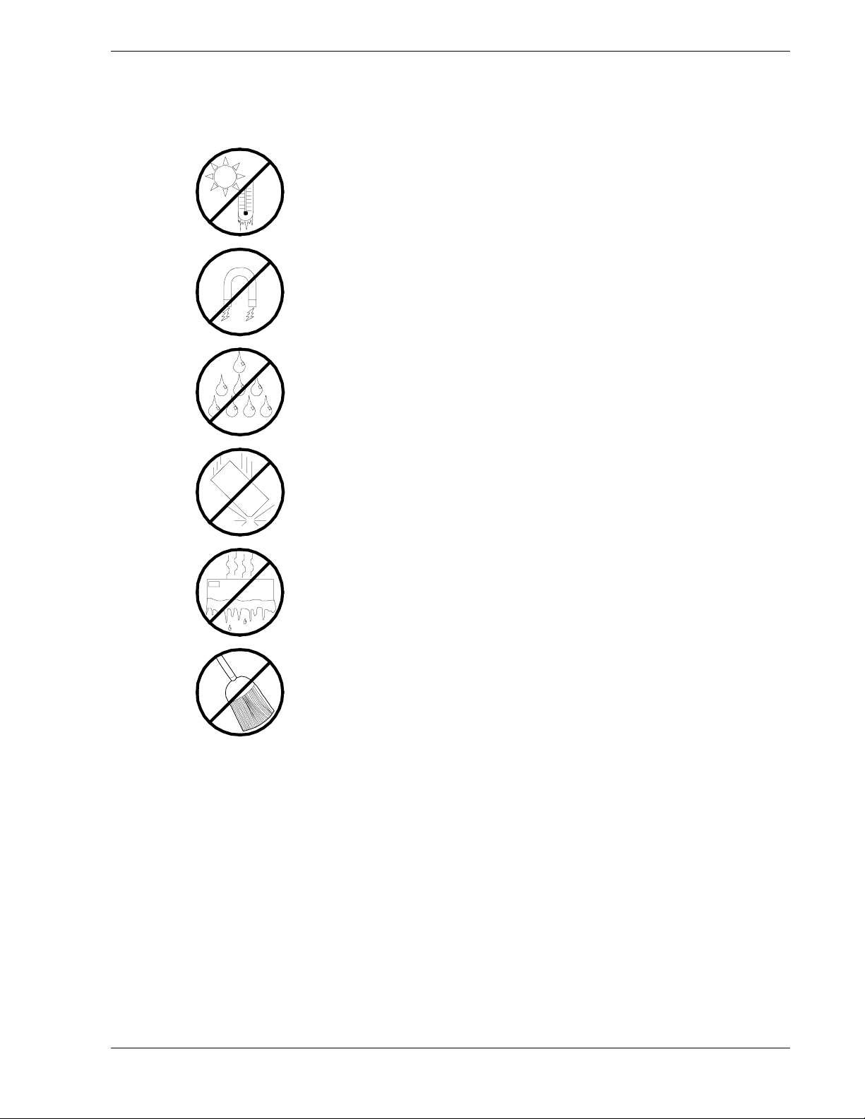
Care and Handling
Use the following guidelines to properly handle and care for your system.
Protect the system from extremely low or high temperatures. Let
the system warm (or cool) to room temperature before using it.
Keep the system away from magnetic forces.
Keep the system dry. Do not wash the system with a wet cloth or
pour fluid into it.
Protect the system from being bumped or dropped.
Check the system for condensation. If condensation exists, allow it
to evaporate before powering on the system.
Keep the system away from dust, sand, and dirt.
Using This Guide xvii


System Overview
! Overview
! System Chassis
! System Board Set
! System Board Set Features
! System Power
! Peripheral Bays
! Disk Array
! System Functions
1
! System Security
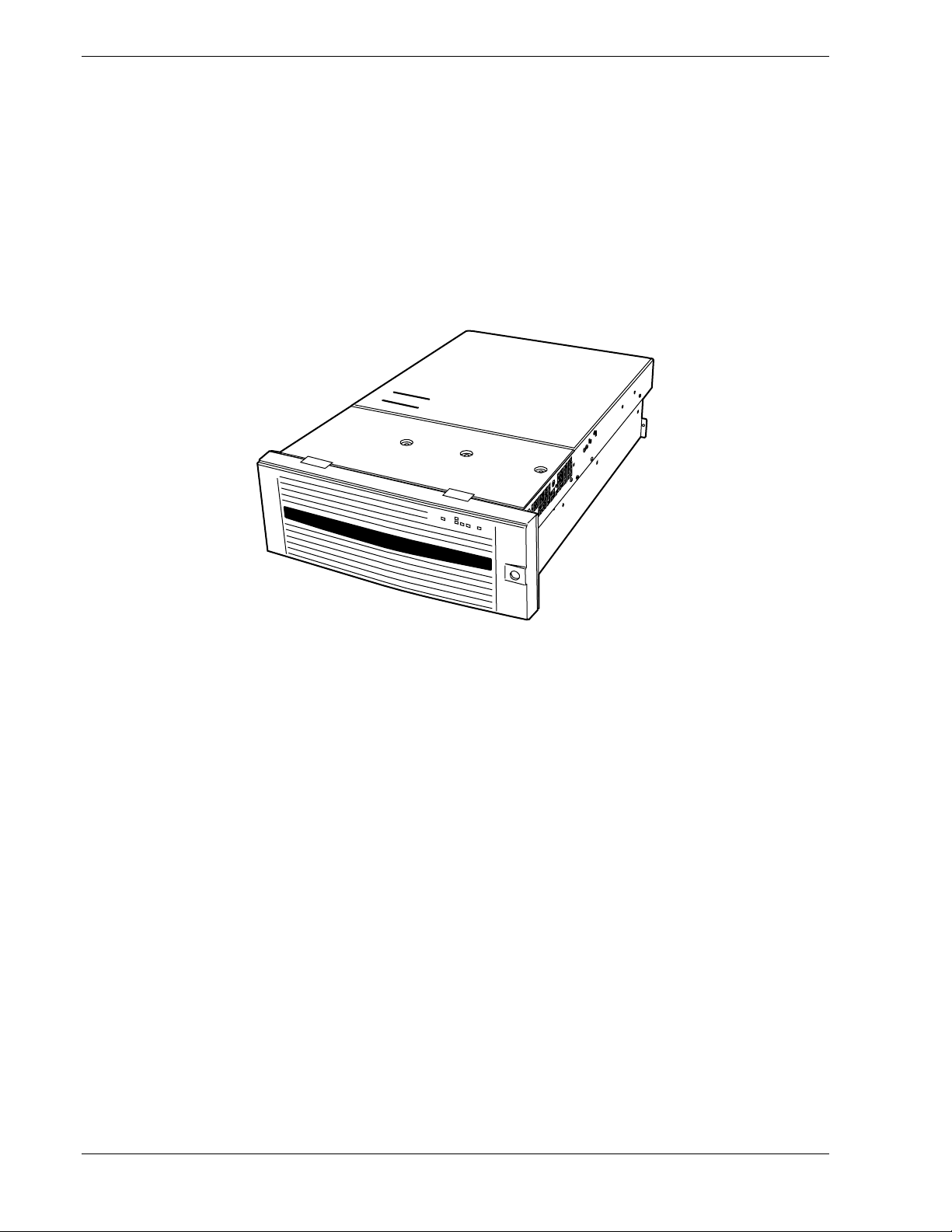
Overview
Your server is a highly reliable, high-powered, fault-tolerant, high-capacity,
multiprocessing server based on the Intel Xeon™ Processor MP. It is a solid performer
and offers the latest technology. The combination of compute performance, memory
capacity, and integrated I/O provides a high performance environment for many server
market applications. These range from large corporations supporting remote offices to
small companies looking to obtain basic connectivity capability such as file and print
services, e-mail, web access, web site server, etc. See Figure 1-1. Your server is housed
and available as a rack-mount system. Your server conveniently installs into a standard
EIA 19-inch rack cabinet.
Figure 1-1. Express5800/140Rc-4 Server
Your server includes a 3.5-inch diskette drive, a CD-ROM drive, a 3.5-inch hard disk
bay, and removable media device bay. The 3.5-inch hard disk bay supports up to five
1.0-inch SCSI hard disk drives that can be swapped in or out of the system without
powering it down, if RAID functionality is configured in the system.
As application requirements increase, you can expand your server with an additional
processor, additional memory, add-in boards and peripheral devices: tape devices,
CD-ROM, and hard disk drives.
The combination of superior computing performance, high memory capacity, and
integrated I/O provides a high performance environment for the many sophisticated
applications available to network servers. The server system is designed for use in
applications where advanced technology, high performance, and high levels of
reliability and compatibility are expected at all times.
1-2 System Overview

Your server is designed for minimum downtime. To this end, the server includes or has
the option to include the following:
! A chassis that supports up to three self-contained power supplies (two are standard
power supplies). An additional power supply can be added to provide redundant
power (i.e., the system will continue to operate with a single power supply failure).
If optional power system redundancy is installed, the power supply units are then
hot-swappable and can be easily installed or removed from the chassis without
turning the system power off.
! Fan modules that can be easily installed or removed from the top of the system. The
fan modules contain a total of six fans for effective cooling. An additional fan cools
the disk drive bay and each power supply contains a fan.
! Cooling system redundancy where the system will continue to operate in the event of
a fan failure or having cabinet temperatures approaching the threshold limit, the
redundant fans will switch to maximum operating speed.
! Up to five SCSI drive bays accessible from the front of the cabinet.
! Hot-swap SCSI disk drive backplane; a failed drive can be removed and replaced
with a new drive without system power being turned off (if an optional Redundant
Array of Independent Disks (RAID) controller is installed.)
! High degree of SCSI disk fault tolerance and advanced disk array management
features through the use of RAID technology, if an optional RAID controller is
installed.
! Hardware monitors (temperature and voltage) and software monitors to indicate
failures.
As application requirements increase, you can expand your server system with
additional processors, additional memory, add-in boards and peripheral devices.
Your server system features the following major components:
! Up to four high-performance Intel Xeon processors.
! Up to 12GB of DDR200 SDRAM four way interleaved memory.
! Eight full-length PCI expansion slots of which four supports 64-bit hot-plug PCI-X
boards, two support 64-bit non-hot-plug PCI-X boards and two support 32-bit nonhot-plug PCI boards. The hot-plug PCI feature is useable only when operating
system support is available.
! Embedded PC-compatible support (serial, parallel, mouse, keyboard, diskette, IDE,
USB, LAN, and video).
! Integrated onboard ATI RAGE XL PCI 64-bit Super Video Graphics Array (SVGA)
controller with 4 MB of video memory.
! Adaptec® AIC7902 SCSI controller providing dual channel Ultra320/160 SCSI
interfaces for the hot swap hard disk drives. This controller also supports Ultra2 and
Ultra Wide SE SCSI devices.
System Overview 1-3
! Two Integrated onboard Network Interface Controllers (NIC), an Intel 82550 NIC
that supports 10Base-T and 100Base-TX networks and an Intel 82544 NIC that
supports 10Base-T, 100Base-TX and 1000Base-T networks.
! Single channel Ultra ATA100 enhanced IDE controller.
! Chassis that holds up to 8 drives; five hot-swap bays for Ultra SCSI hard disk drives;
a 5.25-inch media device bay, a CD-ROM drive installed; and a 3.5-inch diskette
drive installed.
! Five hot-swap SCSI hard disk drive bays accessible from the front of the chassis.
The drives can be swapped in or out of the system without powering down, if RAID
is configured in the system.
! SCSI backplane is Ultra320 capable.
! Integrated triple Universal Serial Bus (USB) ports.
! Two standard power supplies. When an additional power supply is installed, both the
standard and additional redundant power supplies become hot swappable.
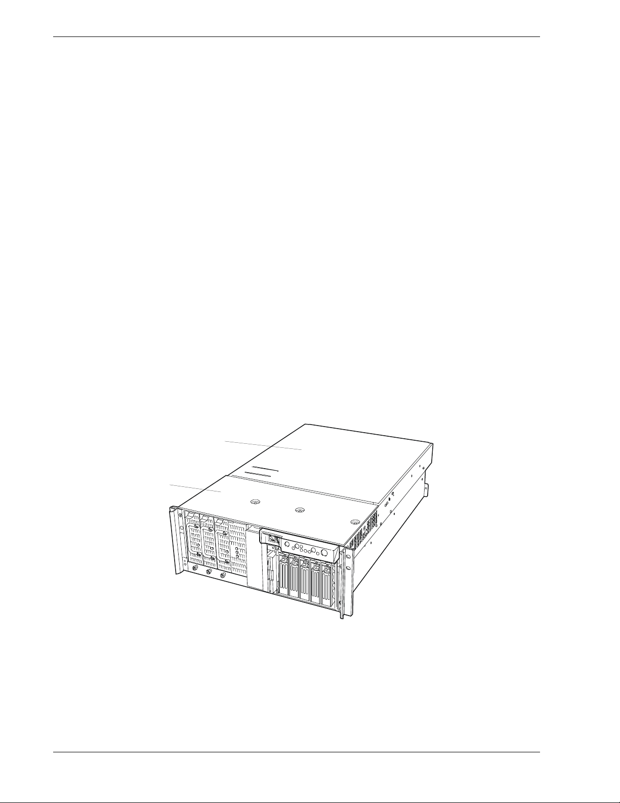
System Chassis
The system chassis (Figure 1-2) is an easy-to-access, fabricated metal structure. The
following subsections describe the main system components, the electronics bay
components, the front panel controls and indicators and the rear panel connectors and
indicators.
Top View
B
A
Front access cover – remove to replace defective fans and to
A
install or remove optional 5.25-inch devices.
Rear access cover – remove to install or remove optional PCI
B
boards, optional processors and DIMMs.
1-4 System Overview
Figure1-2. System Chassis
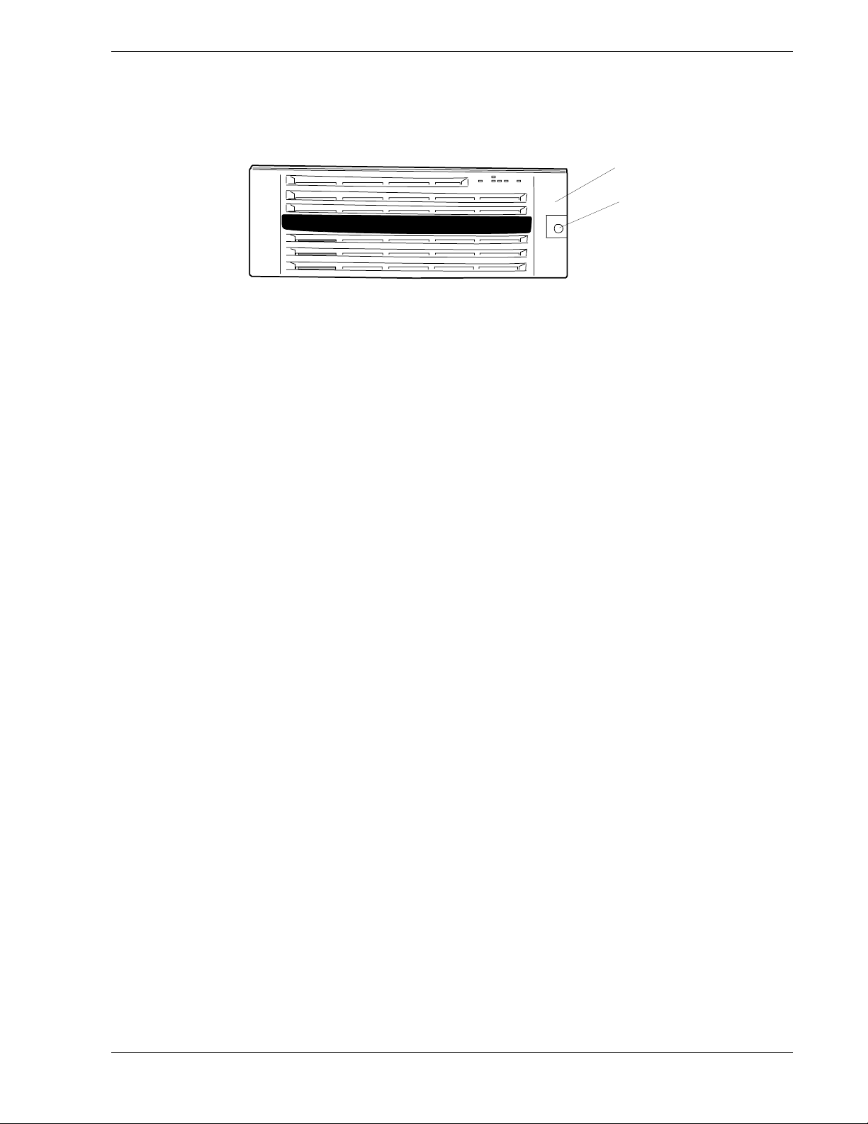
Front View (Bezel Installed)
Figure 1-3 shows the front bezel and keylock.
A Front bezel
Remove the front bezel when you need access to the POWER/SLEEP switch, the CD-ROM
drive, or the floppy disk drive or install or remove a hard disk drive from the 3.5-inch hard
disk bay. The front bezel can be locked by using the attached security key.
BKeylock
Insert the security key to lock/unlock the front bezel.
Figure 1-3. Front View (Bezel Installed)
A
B
System Overview 1-5
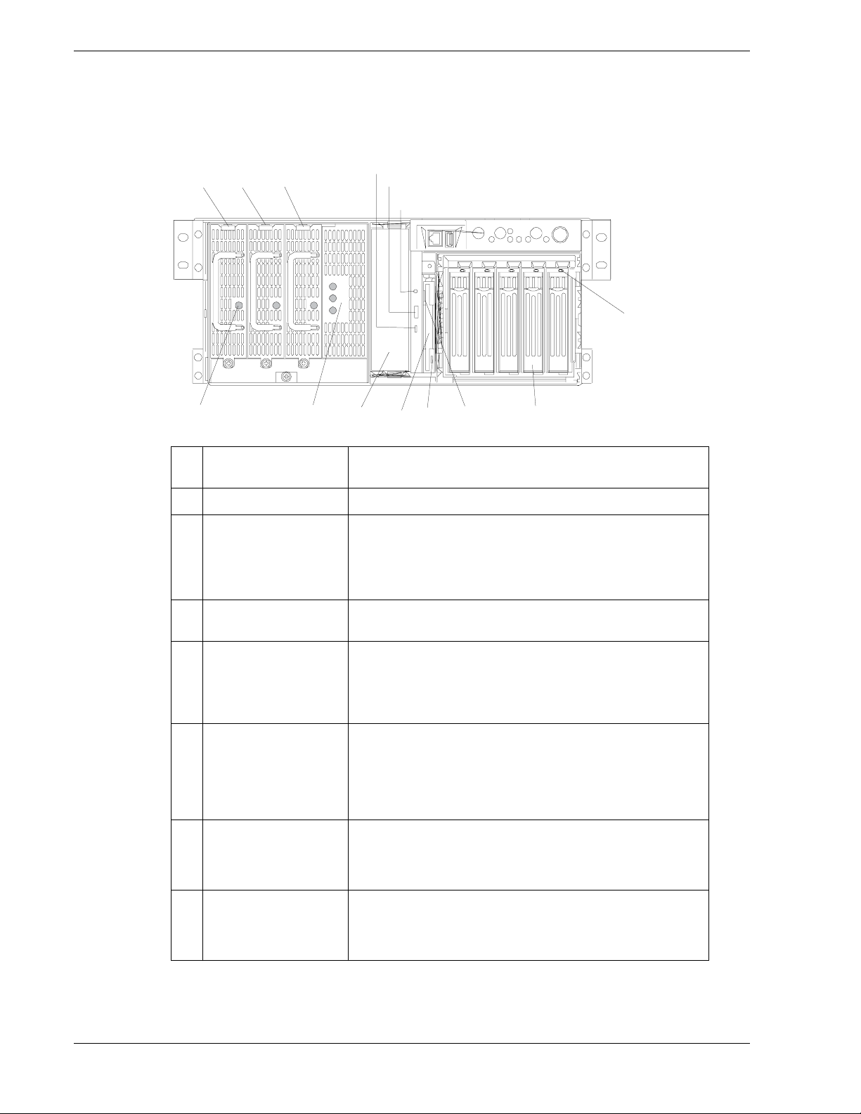
Front Vi ew (Bezel Remo ved)
Figure 1-4 shows the front chassis features and controls visible with the front bezel
removed.
-1BA
-2
A
-3
C D G
A
A Power Unit The power unit supplies DC powers to the server. The slot A-
E
-1
E
-2
E
-3
F
-1F-2F-3
3 is optional power unit slot.
H
B Power lamp Solid green indicates the presence of DC power in the server.
C AC Standby lamp If the power cord is connected to the AC inlet to supply AC
power to the power unit, these lamps are lit green except for
the lamp labeled AC_R. If the power system of the server is
in the redundant mode, after turning on the server, the lamp
indicated AC_R is also lit green. See Table 1-3.
D 5.25-inch device bay Backup tape drives may be installed in the 5.25-inch device
bay.
E CD-ROM drive The CD-ROM drive reads data from the inserted CD-ROM.
E-1: Access lamp (lit orange during accessing)
E-2: CD tray eject button
E-3: Emergency hole
F 3.5-inch floppy disk
drive
G 3.5-inch hard disk bay The 3.5-inch hard disk bay contains additional hard disk slots.
H Disk lamp
(green/amber)
Insert a 3.5-inch floppy disk to the 3.5-inch floppy disk drive
to read data from the disk or write data to the disk.
F-1: Disk inserting section
F-2: Floppy disk access lamp (lit green during accessing)
F-3: Eject button
Hard disks having the thickness of 1 inch can be inserted into
the slots. The SCSI IDs are defined as follows: ID0 to ID4
from right to left.
The disk lamp is lit green if a hard disk installed in the server
is accessed. If a hard disk is defective, the lamp is lit amber.
During the rebuild processing, the lamp is lit green or amber
alternately. (This occurs only in the disk array configuration.)
1-6 System Overview
Figure 1-4. Front View (Bezel Removed)

Front Panel Switches, Connectors and LED Indicators
Figure 1-5 shows the front panel switches, connectors and LED indicators
A B C D E F G H
I J K K L
A Serial port B connector The serial port B connector is used to connect the server to a device with the
serial interface.
The server cannot be directly connected to a leased line through the connector.
IMPORTANT: Only the RJ-45 serial interface cable can be connected to this port.
Do not connect any other interface cables such as the Ethernet cable. Doing so
could damage the device, your server, or both.
B USB3 connector The USB3 connector allows the server to be connected to a device accepting the
USB interface.
C SLEEP switch Pressing the sleep switch once causes the server to enter into the sleep state
(power saving mode). Pressing the power switch in the sleep state recovers the
machine to the normal state. (This function is supported by Windows 2000.)
D UID (Unit ID) switch Pressing the UID switch turns UID lamp (blue) located on the front panel and the
rear panel on and off. The UID lamp located on the rear panel is visible through
the rear of the chassis and allows you to locate the server you're working on from
the rear of the servers on a rack.
E UID lamp (blue) Lights blue when the ID switch is pressed.
F RESET switch The reset switch is used to reset the server.
G POWER/SLEEP lamp
(green)
H POWER switch The power switch is used to turn power on/off. If you press the switch once, then
I Dump switch The dump switch is used to collect the event log data.
J STATUS lamp
(green/amber)
K LAN1/LAN2 ACCESS lamp
(green)
L DISK ACCESS lamp
(green/amber)
Lights green when the server is powered on. Goes off when the server is
powered off. Blinks when the system is placed in the sleep mode.
the POWER/SLEEP lamp goes on and the power is turned on. If you press the
switch again, the power is turned off. The system is forcibly shut down when the
power switch is pressed continuously for four seconds or longer.
Lights green while the server is in successful operation. When any error is
detected, this lamp lights or blinks amber.
Lights green while the server is connected to the network. Blinking green
indicates the network activity. Numbers printed near the lamps indicate the LAN
port number.
Lights green while the internal hard disk is in access. When any one of the
internal hard disks fails, this lamp lights amber.
Figure 1-5. Front Panel Switches, Connectors and LED Indicators
System Overview 1-7
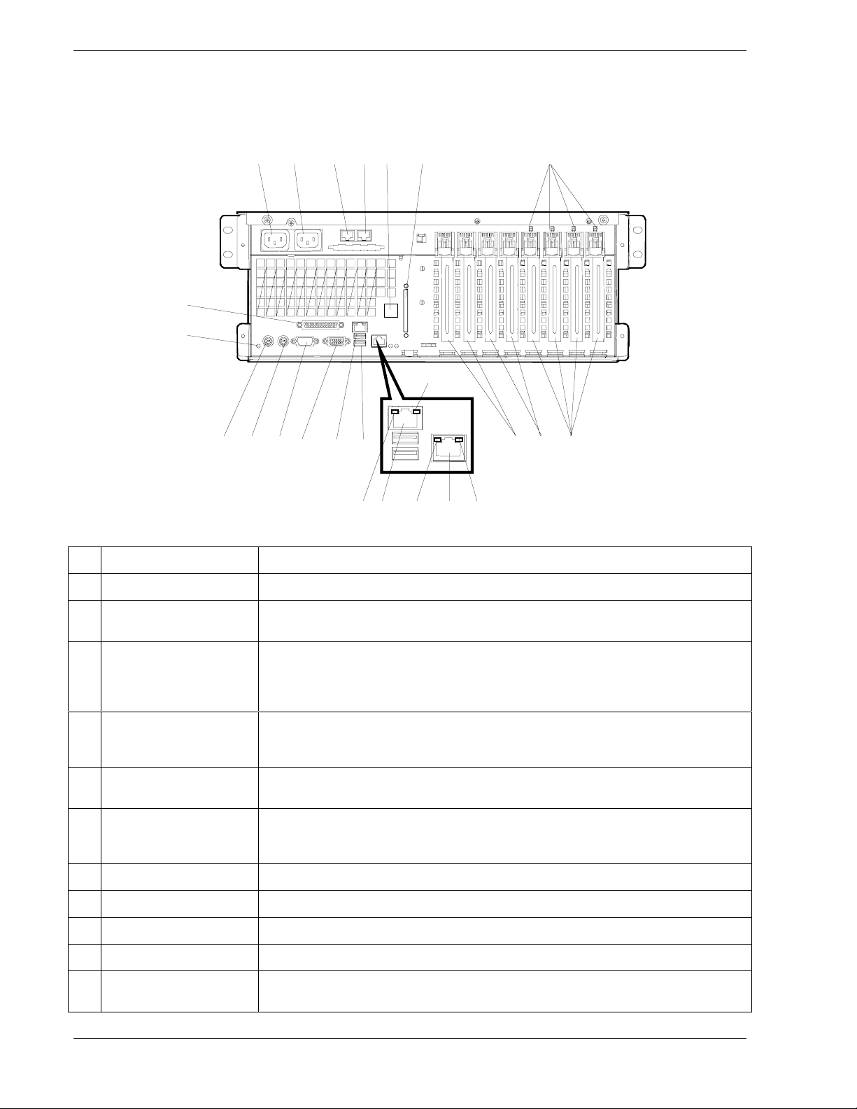
Rear View
Figure 1-6 shows the rear chassis features and controls.
AB C2DE
C1
F
G
H
I J K L M1 N O P
A AC inlet 1 The AC inlet 1 is connected with the power cord coming with the server.
M2
QR STUQ
B AC inlet 2 The AC inlet 2 is used when the additional power unit is installed in the server.
C ICMB-1 (left) ICMB-2
(right) connector
D Serial port B connector The serial port B connector is used to connect the server to a device with the serial
E External SCSI connector The external SCSI connector is used to connect the server to external SCSI devices.
F PCI slot power lamp
(green) (upper)
F PCI slot fault lamp
(amber) (lower)
G Printer port connector The printer port B is used to connect a printer to the system.
H UID lamp (blue) This lamp is lit when the UID switch is pressed.
I Keyboard connector The keyboard connector is used with PS/2 type keyboard.
J Mouse connector The mouse connector is used with the PS/2 type mouse.
K Serial port A connector The serial port A connector is connected with a device having the serial interface. The
The ICMB connector is connected to a device having the ICMB interface.
interface. The server cannot be directly connected to a leased line through the
connector. For using this port, the rear serial cable that comes with your server
should be connected to this connector.
For connection, attached SCSI cable is necessary and some cable connections must
be changed on the system board.
The PCI slot power lamp is lit when the power of the PCI slot is turned on.
PCI slot fault lamp blinks when the hot plug PCI function is enabled with Windows
2000. This lamp also goes on if a fault occurs in the PCI board installed into the slot
or the slot itself.
server can't directly be connected to a leased line through the connector.
1-8 System Overview

L Monitor connector The monitor connector is connected with the display unit.
M USB-1 - USB-2
connectors
N Additional PCI board
slots
O Additional PCI board
slots
P Additional PCI hot-plug
board slots
Q LINK/ACT lamp The LINK/ACT lamp shows the LAN access status.
R LAN1 connector The LAN1 connector is connected with a network system on LAN. This port can be
S LAN2 connector The LAN2 connector is connected with a network system on LAN. This port can be
T 100/10 lamp The 100/10 lamp indicates the LAN transfer rate.
U 1000/100/10 lamp The 1000/100/10 lamp indicates the LAN transfer rate.
The USB-1 (upper) and USB-2 (lower) connectors are connected with devices
accepting the USB interface.
Optional PCI boards (32-bit/33MHz) may be inserted into the slots.
Optional PCI boards (64-bit/100 MHz) may be inserted into the slots.
Optional PCI hot-plug boards (64-bit/100 MHz) may be inserted into the slots.
operated through 100BASE-TX or 10BASE-T interface.
operated through 1000BASE-T, 100BASE-TX or 10BASE-T interface.
Figure 1-6. Rear View
System Overview 1-9
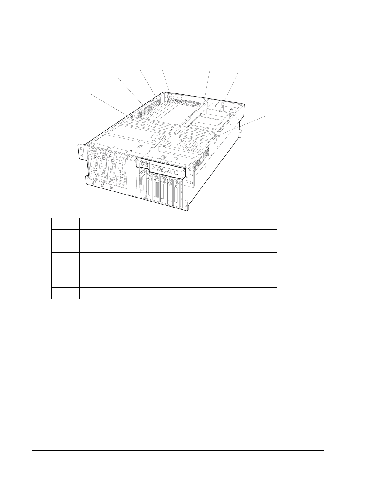
Internal View
Figure 1-7 shows an internal view of the server.
C
D
B
A
A Fan bay (6 Cooling fans are located in this bay.)
B Electronics bay
E
F
G
C Additional PCI board slots (8 slots)
D Hot Plug PCI LED Board
E Memory board
F Processor board air duct
G Cover open sensor
Figure 1-7. Internal View
1-10 System Overview

Electronics Bay
Figure 1-8 shows the electronics bay.
A
B
C
D
A Hot-plug PCI board slots
B Non-hot-plug PCI board slots
C Dummy sponge
D Processor board
E System board
E
Figure 1-8. Electronics Bay
System Overview 1-11

Status LED Indicator Descriptions
Table 1-1 lists the system status LED indicators along with a description of each LED
indicator. Table 1-2 lists the disk drive status LED panel indicators along with a
description of each LED indicator. Table 1-3 lists the power supply status LED panel
indicators along with a description of each LED indicator. Table 1-4 lists system status
abnormal conditions.
The access LED indicators for the CD-ROM drive and the diskette drive light when
access is being made to the media in the drive.
Table 1-1. System Status LED Indicators (Figure 1-5)
LED Status Description Response
Power Off Power OFF None required (normal)
Green Power ON None required (normal)
(Flashing
green)
Status Off
(Turns off after
lighting in
amber)
Green
(Steady light)
(Flashing light)
Amber Abnormal condition
Disk Off Not accessing disk
Amber Internal disk drive
Green Accessing disk
LAN1/LAN2 Off Server not
Power saving mode
(Sleep mode)*
Power OFF
Abnormal condition
(see Table 1-4)
No alarms
Abnormal condition
(see Table 1-4)
(see Table 1-4)
drives
failure
drives
connected to a LAN
None required (normal)
None required (normal)
Check condition
None required (normal)
Check condition
Check condition
None required (normal)
Check disk drive status LEDs
None required (normal)
None required (normal)
UID (unit ID) OFF/ON (blue) Turn on to identify
* Requires a operating system support.
1-12 System Overview
Green Server connected to
a LAN
(Flashing
green)
Server accessed
through a LAN
the server you are
working on. Visible
from the front and
rear of the server.
None required (normal)
None required (normal)
None required (convenience LED)

Table 1-2. Disk Drive Status LED Panel Indicators (Figure 1-4)
LED Status Description Response
Disk Drive
Power/access
/error
*Disk array configuration only
Off Disk drive
power off
Green Disk drive
power on
Flashing
green
Amber Disk drive failure* Replace disk drive
(Alternating
between
amber and
green)
Accessing disk drive None required (normal)
Rebuilding* LED
goes off when
rebuilding is
complete.
Remount the disk drive
None required (normal)
None required (normal)
Table 1-3. Power Supply Power and Status LED Indicators (Figure 1-4)
LED Status Description Response
PWR Off Power off None required (normal)
On (green) Power on None required (normal)
SB1/SB2 Off Power not
connected to AC
inlets.
On (green) Power connected to
AC inlets.
AC_R Off Non-redundant
power configuration
On (green) Three power
supplies installed.
Redundant power
configuration.
Connect power cords to AC inlets 1
and 2.
None required (normal)
None required (normal)
None required (normal).
System Overview 1-13

Table 1-4. System Status Abnormal Conditions (Figure 1-5)
Status LED Description Response
Off POST is in progress. Wait for a while. It lights green a few seconds after
completion of POST.
CPU error is detected. Turn the server off and then back on. If an error
message appears during POST, take note of the error
message and contact your technical support
representative.
Green
(Flashing light)
Amber
(Steady light)
Amber
(Flashing light)
CPU temperature error is detected.
(Thermal-Trip)
Watchdog timer has timed out. Same
Uncorrectable error is detected in the
memory.
PCI system error is detected. Same
PCI parity error is detected. Same
CPU bus error is detected. Same
Memory dump request is being
issued.
Memory or CPU is degraded. Use the BIOS setup utility, SETUP, to locate the
Critical temperature error is detected. Check if any fan inside the server has dust on it. Make
Critical voltage error is detected. Contact your technical support representative.
Power supply failed. Contact your technical support representative.
A power alarm was detected in each
power system.
Same
Same
Wait until the memory dump finishes.
degraded device and replace it as soon as possible.
sure that fan cables are firmly connected.
If the lamp indication still does not change, contact
your technical support representative.
Identify the failed power supply unit and contact your
technical support representative.
Fan alarm is detected. Make sure fan cables are firmly connected.
Temperature alarm is detected. Check if any fan inside the server has dust on it. Make
Voltage alarm is detected. Contact your technical support representative.
1-14 System Overview
If they are and the lamp indication still does not
change, contact your technical support representative.
sure that fan cables are firmly connected.
If the lamp indication still does not change, contact
your technical support representative.

System Board Set
The system board set inside the server includes the system board, memory board, and
processor board.
Figures 1-9, 1-10, and 1-11 show the major components on the system board, memory
board, and processor board. Table 1-5 summarizes the features of the board set.
Table 1-5. Features of the Board Set
Feature Description
Multiple processor
slots
Four processor sockets on the system board.
Upgradeable
memory
Hot Plug PCI slots Four hot-plug PCI-X add-in board slot locations (Figure 1-6, A), two non-hot-
SCSI controller Adaptec AIC7902 SCSI controller providing dual channel Ultra320/160 SCSI
BIOS Flash memory-based BIOS (Basic Input/Output System) and Setup utilities.
Video Integrated super SVGA controller ships with 4 MB of video memory.
External device
connectors
Clock Real-time clock/calendar (RTC).
System hardware
monitoring
Twelve DIMM sockets on a single memory board, supporting up to 12GB
memory using 1GB DIMMs. Must use four sticks (4-way interleaving)
double-sided buffered type only.
plug PCI-X add-in board slot locations (Figure 1-6, B) and two non-hot-plug
PCI add-in board slot locations (Figure 1-6, C). The four hot-plug PCI-X
board slot locations are dedicated 64-bit, 100 MHz PCI-X bus slots. The two
non-hot-plug PCI-X board slot locations are dedicated 64-bit, 100 MHz
PCI-X bus slots. And the two non-hot-plug PCI board slot locations are
dedicated 33-bit, 33MHz PCI bus slots.
interfaces for the hot swap hard disk drives. This controller also supports
Ultra2 SCSI devices.
Connectors for two serial ports, parallel printer port, wide SCSI port, three
USB connectors, one 10/100 BaseTX connector and one 10/1 00/1 000
BaseT connector, two optional ICMB port connectors, PS/2-compatible
keyboard and mouse, and SVGA monitor.
Contains power interlock switch and sensors for temperature, voltage, and
fan failure.
Configuration
utilities
BIOS Setup and SCSISelect Configuration Utility.
System Overview 1-15

CC DDEE
FF
GG
HH
JJ
KK
LL
BB
A
B
AA
Z
Y
X
W
V
C
D
E
F
U
N
QRST
M
P
A 64-bit, 100-MHz, hot-plug PCI-X slots U 14-pin Power Control connector (P35)
B 64-bit, 100-MHz, non-hot-plug PCI-X slots V 24-pin Power connector (P32)
C 32 bit, 33-MHz, non-hot-plug PCI slots W 20-pin Power connector (P28)
D Intelligent Chassis Management Bus
(ICMB) connector (P24)
E Hot-Plug Indicator Board Connector (P23) Y USB #3 Header (P18)
F Back Panel I/O connectors Z Front Panel Header (P19)
G Intel ® 82550 Ethernet controller AA IDE Connector (P13)
H ATI Rage XL 2D/3D graphics accelerator BB SCSI LVD connectors (P4 and P7)
J Intel ® 82544 Ethernet controller CC Intelligent Platform Management Bus (IPMB)
K Video RAM (VRAM) (4 MB total) DD Adaptec 7902 SCSI controller
L Processor board connectors (P21 and
P22)
M ServerWorks South Bridge Controller FF ServerWorks PCI-X Bus Bridge Controller
N BMC component GG ServerWorks PCI-X Bus Bridge Controller
P BIOS Flash component HH RAID LED connectors (P1 and P2)
Q PC87417 Super I/O controller JJ Hot-swap backplane (HSBP) connector (P16)
R BMC Flash component KK HSBP connector (P15)
S Battery LL Jumper block JP4
T Chassis Intrusion Detect connector (P36)
X Serial port B connector (P17)
connector (P12)
EE Fan connector (P11)
GHJKL
Figure 1-9. System Board Component Locations
1-16 System Overview

DIMM Group 3
DIMM Group 2
DIMM Group 1
11
9
7
5
3 4
1 2
A
Note: DIMMs are grouped into four and must be installed in
multiples of four. Group 1 DIMMs are installed in the system. When
adding DIMMs, install DIMMs into Group 2, then Group 3. When
removing DIMMs, remove DIMMs in Group 3 first, followed by Group
2, and lastly Group 1.
Group #1 DIMM sockets (DIMM slots 1, 3, 2, 4)
Group #2 DIMM sockets (DIMM slots 5, 7, 6, 8)
Group #3 DIMM sockets (DIMM slots 9, 11, 10, 12)
A = System board connector
12
10
8
6
DIMM Group 3
DIMM Group 2
DIMM Group 1
Figure 1-10. Memory Board Component Locations
C
D
AB
A Processor (CPU) #1
B Processor (CPU) #2
C Processor (CPU) #3
D Processor (CPU) #4
Figure 1-11. Processor Board Component Locations
System Overview 1-17

System Board Set Features
The following subsections provide a description of the system board set features.
Intel Xeon Processor
Depending on system configuration, your server includes from one to four Intel Xeon
processors. Available processor speeds are 1.5GHz, 1.9GHz, and 2.0GHz. Each Intel
Xeon processor plugs into a ZIF (Zero Insertion Force) socket on the system board. The
processor includes a numeric coprocessor, a 1MB or 2MB L3 cache, and operates at a
bus speed of 400MHz. Up to four optional processors enhance performance and enables
symmetric multiprocessing (SMP).
System Memory
The memory board contains twelve 168-pin DIMM slots each supporting 72-bit ECC
(64-bit main memory plus ECC) registered PC-200 Double Data Rate (DDR) DIMMs.
Memory is partitioned in three banks. You may install a minimum of 512 MB
(128 MB x 4) or as much as 12 GB. The controller automatically detects, sizes, and
initializes the memory array, depending on the type, size, and speed of the installed
DIMMs, and reports memory size and allocation to the server via configuration
registers.
Note: Only use DIMMs approved for use in this server system.
Call your customer service representative for information.
I/O Expansion Slots
The server's expansion capabilities meet the needs of file and application servers for
high performance I/O by providing a combination of 32-bit and 64-bit PCI expansion
slots.
The system board has four full-length hot-plug 64-bit, 100 MHz PCI-X connectors, two
non-hot-swap full-length 64-bit, 100 MHz PCI-X connector slots and two non-hot-swap
32-bit 33 MHz PCI connector slots. See Table 1-5.
Real-Time Clock/Cale ndar
The real-time clock provides system clock/calendar information stored in a non-volatile
memory (NVRAM). The real-time clock battery provides power backup for the realtime clock.
BIOS
The BIOS and Setup Utility are located in the Flash EPROM on the system board and
include support for system setup and legacy device configuration. A number of security,
reliability, and management features also have been incorporated to meet vital server
needs.
1-18 System Overview

Controllers
The following provides a description of the controllers.
IDE Controller
The system includes a single channel enhanced IDE 32 bit interface. The IDE controller
provides support for the internally mounted CD-ROM.
The device controls:
! PIO and DMA transfer modes
! Mode 4 timings
! Transfer rates up to 100 MB/s
! Buffering for PCI/IDE burst transfers.
Keyboard and Mouse Controller
The keyboard and mouse controller are PS/2 compatible.
Network Interface Controller
The system board includes two network interface controllers (NICs):
! Intel 82550 NIC that supports 10Base-T and 100Base-TX networks
! Intel 82544 NIC that supports 10Base-T, 100Base-TX networks, and 1000BASE-T
networks.
The 82550 controller supports the following features:
! 32-bit PCI, CardBus master interface
! Integrated IEEE 802.3 10Base-T and 100Base-TX compatible PHY
! IEEE 820.3u auto-negotiation support
! Chained memory structure similar to the 82559, 82558, 82557 and 82596
! Full duplex support at both 10 Mbps and 100 Mbps operation
! Low power +3.3 V device
! IP checksum off-loading.
NIC 1 can be used as both a network interface and server management interface.
The 82544 controller supports the following features:
! Direct 32/64-bit, 33/66-MHz interface to the PCI bus
! Integrated IEEE 802.3 1000BASE-T, 100BASE-TX, and 10BASE-T
! Integrated third-generation MAC and proven IEEE 803.3ab compatible PHY
! Full duplex support for 10-Mbps, 100-Mbps, and 1000 Mpbs operation
System Overview 1-19

! Descriptor ring management architecture optimized to deliver both high performance
and PCI/PCI-X bus efficiency
! Low power +3.3 V device
! IP and TCP/UDP checksum off-loading.
SCSI Controller
The system board includes an embedded Adaptec 7902 SCSI controller, which contains
two independent SCSI channels. You can disable the SCSI controller in BIOS Setup.
Both channels support 16-bit SE or LVD SCSI operations at the following speeds:
! Ultra320 (320 MB/sec)
! Ultra160 (160 MB/sec)
! Ultra2 (80 MB/sec)
! Ultra Wide SE (40 MB/sec)
The system board provides active terminators, termination voltage, resettable fuses, and
protection diodes for both SCSI channels. You can disable the onboard terminators in
BIOS Setup.
Video Controller
The system board incorporates an ATI RAGE XL PCI graphics accelerator with 4 MB
of video SDRAM that supports all standard IBM VGA modes. The embedded SVGA
video subsystem supports:
! Pixel resolutions up to 1024 x 768
! CRT and LCD monitors up to 100 Hz vertical refresh rate
The system board supports disabling of the onboard video through BIOS Setup or when
a plug-in video card is installed in any of the PCI slots.
Peripheral Controller
The advanced integrated peripheral controller supports two serial ports, three universal
serial bus ports, one parallel port, diskette drive, PS/2-compatible keyboard and mouse,
and integrated Real Time Clock (RTC). The system provides the connector interface for
each port.
System Board Management Controller (BMC)
Server management is concentrated in the System Board Management Controller
(BMC). The BMC and associated circuitry are powered from a 5Vdc standby voltage,
which remains active when system power is switched off, but the ac power source is
still on and connected.
The BMC supports the Management Workstation Application (MWA), which allows
remote server management via a modem, LAN, or direct connection to a manager
system. Events monitored by the manager system include over-temperature and overvoltage conditions, fan failure, or chassis intrusion.
1-20 System Overview

One major function of the BMC is to autonomously monitor system management
events, and log their occurrence in the nonvolatile System Event Log (SEL). The events
being monitored include overtemperature and overvoltage conditions, fan failure, or
chassis intrusion. To enable accurate monitoring, the BMC maintains the nonvolatile
Sensor Data Record (SDR), from which sensor information can be retrieved. The BMC
provides an ISA host interface to SDR sensor information, so that software running on
the server can poll and retrieve the server's current status.
The BMC performs the following:
! Monitors server board temperature and voltage
! Monitors processor presence and controls Fault Resilient Boot (FRB)
! Detects and indicates system board fan failure
! Manages the SEL interface
! Manages the SDR Repository interface
! Monitors the SDR/SEL timestamp clock
! Monitors the system management watchdog timer
! Monitors the periodic SMI timer
! Monitors the event receiver
! Controls secure mode, including video blanking, diskette write-protect monitoring,
and front panel lock/unlock initiation
! Controls Wake On LAN via Magic Packet support.
External Device Connectors
The external I/O connectors provide support for a PS/2 compatible mouse and a
keyboard, a SVGA monitor, 2 serial port connectors, a parallel port connector, two
LAN ports, two USB ports, and one external-SCSI connector.
System Overview 1-21

System Power
The system contains two auto-sensing 430 watt power supplies at an operating
frequency of 50/60 Hz. A third optional power supply may be added as part of a faulttolerant hot-swap design. With three power supplies installed, in the unlikely event of a
power supply failure, the load is transferred to the remaining power supply without
interruption to normal operation. In this case the faulty power supply can be replaced
without powering down the system.
Note: The power supplies are not hot-swappable unless there
are three supplies installed.
The power supplies are designed to comply with existing emission standards and
provide sufficient power for a fully loaded system configuration.
Peripheral Bays
The system supports a variety of standard PC AT-compatible peripheral devices. The
chassis includes these peripheral bays:
! A 3.5-inch front panel bay for mounting the standard 3.5" diskette drive (supports
720 KB and 1.44 MB diskette media)
! A 5.25-inch removable media front panel bay for mounting half-height 5.25-inch
peripheral devices: optional tape drives and optional additional CD ROM drive, etc.
! A front panel bay for mounting the standard CD-ROM drive.
! A SCSI hard disk drive bay for mounting up to five SCSI hard disk drives in easily
removable drive carriers. Each drive has one LED to indicate a fault or other status:
power-on/activity (green LED), and fault (amber LED). The SCSI disk drives can be
easily installed or removed. The drive carrier allows you to access disk drives from
the front of the system. If disk drives are used in a RAID configuration within the
system, a disk drive can be swapped with another without power interruption to the
system (hot-swap).
Note: The SCSI hard disk drive bays contain a hot-swap back
panel that require an 80-pin single connector attachment (SCA)
connector on the drives that you install.
1-22 System Overview

Disk Array
The optional disk array controller board is a PCI board that can improve data reliability.
The disk array controller board allows the hard disk drives in the SCSI hard disk drive
bays and additional optional disk expansion unit to support disk array configuration
RAID levels 0, 1, and 5.
RAID is an acronym of “Redundant Arrays of Inexpensive (Independent) Disks”. It
logically integrates several hard disks to appear to the system as only one disk drive.
Using the disk array method, the large-capacity hard disk can be configured with
several inexpensive and small-capacity hard disks. It can also enhance the drive by
improving the reliability and supporting an automatic rebuilding function.
All RAID levels are common in their basic operation due the fact that several hard disks
can be recognized as one disk drive. However, performance, cost, and use are
conditions that vary according to the RAID level. You should select an appropriate
configuration that is suitable for your system.
Features and selection examples of different RAID levels are shown below.
Level Definition Redundancy Feature Suitable
application
RAID0 Striping No Access: high-speed. Application that
needs high
performance for
non-critical data
RAID1 Mirroring
(or
shadowing)
RAID5 Striped
data and
parity
Yes Dual disk system.
Read mode: highspeed
Write mode: slower
than RAID 0
Yes Parity data.
Transfers large
amount of data.
Write mode: slower
than RAID 0
Application that
needs to store
important files
on main system
drive
Application that
needs to store
important data.
Application of
read-intensive
type
data searching.
Minimum
No. of disks
2
2
3
This unit supports other RAID levels as well. However, it is not recommended to use
them unless absolutely necessary.
System Overview 1-23

Automatic Rebuilding Function
The server supports the disk array automatic rebuilding function for data recovery.
Note: The automatic rebuilding function supports RAID levels
RAID1 or RAID5.
Rebuilding is to regenerate all data from a failed disk to a replacement disk. A rebuild is
necessary after a failed disk drive is replaced with a new one.
With RAID levels RAID1 or RAID5 the failed disk does not affect the operation.
However, if another disk error occurs before automatic rebuilding is complete, the data
may be destroyed.
In a conventional server, the user must select and execute rebuilding using various
utilities. This server executes rebuilding automatically. Since the server also supports
hot-swapping function, the failed disk can be replaced while the power is on.
Observe the following when using an automatic rebuilding function.
! Do not turn the power off. If power is turned off, automatic rebuilding will not start.
! Use an interval of 60 seconds or more between mounting and dismounting the hard
disk drive.
! If a hard disk is being rebuilt, do not replace the hard disk.
Expand Capacity Function
Disk capacity can be expanded by adding a disk drive while the system is running. This
function is only supported if the server is in the disk array configuration mode.
This function does not utilize operations such as data backup, pack reconfiguration,
initialization, restoring the data or reconfiguring the partitions on the drive.
If a hard disk is added under the operation of the Global Array Manager, perform the
following.
! After the hard disk is installed, wait for about 60 seconds and click the Scan Device
key. Clicking the Scan Device key after the execution of the expand array operation,
will display the added disk correctly.
1-24 System Overview

System Functions
The following subsections describe select system functions.
Hot Swapping
Hot swapping allows a device to be replaced, such as a hard disk drive while its power
is on, as listed below.
! Disk array system:
Any failed hard disk drive can be replaced while the system is running, except when
the drives are configured as RAID 0.
! Hot swap fans:
Any one of the six system fan modules can be replaced while the system power is
on.
! Redundant Power system:
When three power supplies are installed in the system, a failed power supply can be
replaced by hot swapping.
Hot Plug PCI
Four Hot Plug PCI bus slots are located behind the access cover of the server. These
PCI slots allow PCI-X boards to be installed or removed while the server is powered on
(if the operating system supports the Hot Plug PCI function.)
Fans
Note: Windows NT 4.0 does not support the Hot Plug PCI
function.
!
CAUTION
All access covers must be on the system for proper cooling. To
ensure that all components remain within specification under all
system environmental conditions, do not exceed five minutes for hot
swapping of fans or hot plug PCI boards.
The server contains six fan modules. Air enters through the bezel, passes through the
fan bay and electronics bay, and exhausts through the rear of the chassis.
Under normal system conditions, the fans run at a slower, quieter speed. If a fan failure
is sensed, a fan is not detected, or ambient temperature exceeds a certain limit, the fan
speed is set to high. Also, any one of the six system fan modules can be replaced while
the system power is on.
LEDs indicate if individual fans are inoperative or not present. Under the same fan
failure conditions, the general system fault LED on the front panel is lit.
System Overview 1-25

Sleep Mode
The SLEEP mode switch on the front of the server is used for saving power.
If the SLEEP mode switch is pressed, then the server enters into the sleep state (the
Drive Bay Power lamp and the Power lamp will blink simultaneously). In the power
saving mode, the memory data and the states of the jobs are kept unchanged. In
addition, the server in the power saving mode can accept accesses to hard disks from
other machines on the network and perform other network jobs.
Sleep mode requires an operating system that supports its function.
ACPI
The Advanced Configuration and Power Interface (ACPI) aware operating system can
place the system into a state where the hard drives spin down, some system fans stop,
and all processing is halted. However, in this state the power supply is still on and the
processors are still dissipating some power such that the power supply fan and some
system fans are still running.
This server system BIOS supports sleep states s0, s1, s4, and s5.
Note: ACPI requires an operating system that supports its
feature.
The sleep states are defined as follows:
! s0: Normal running state.
! s1: Processor sleep state.
No context will be lost in this state and the processor caches will maintain
coherency.
! s4: Hibernate or Save to Disk.
The memory and machine state are saved to disk. Pressing the power button or other
wakeup event restores the system state from the disk and resumes normal operation.
This assumes that no hardware changes have been made to the system while it was
off.
! s5: Soft off.
Only the RTC section of the chip set and the BMC are running in this state.
AC Link Mode
The AC link mode allows the system to monitor its AC input power so that when the
AC input power is lost and then restored the system will return itself to one of three preselected settings, listed as follows:
!
CAUTION
Only when the AC power is disconnected is the system completely
off.
! Power On
1-26 System Overview

! Last State (Factory Default Setting)
! Stay Off.
The AC link mode settings can be changed by running the BIOS Setup Utility (F2).
Refer to Chapter 3 "Configuring Your System."
Remote Power-On (Wake On LAN) Function
The remote power-on function turns on the system power by way of a network or
modem. If the system power is set to Off, it can be turned on remotely by sending a
specific packet from the main computer to the remote system.
Note: The standard default value of the remote power-on
function is “Disabled”. To enable it, the Wake On LAN item in the
System Hardware menu of the BIOS Setup Utility described in
Chapter 3 “BIOS Setup Configuration Settings” must be changed to
“Enabled.”
Reconfiguration
If a CPU or a memory DIMM error was detected during execution of POST (Power On
Self-Test) after system power is turned on, the reconfiguration function isolates the
failed CPU or memory DIMM and continues operation. You should replace the failed
device as soon as possible.
This function is enabled only when either of the following system requirements are met:
! Two or more CPUs are installed.
! Eight or more memory DIMMs are installed.
A CPU or memory DIMM error may be viewed on the screen while POST is running or
by entering BIOS Setup. It may also be viewed when the ESMPRO Suite program is
installed and operating.
SAF-TE Logic
The SCSI backplane includes SAF-TE (SCSI Accessed Fault Tolerant Enclosure) logic
that provides an interface to the disk subsystem that supports status signals, hot
swapping drives, and enclosure monitoring. The transport mechanism for the
standardized alert detection and status reporting is the SCSI bus. Disk drives, power
supplies, cooling fans, and temperature are continually monitored and the conditions
then reported over the SCSI bus to the system. When used with RAID management
software the user can be alerted of impending or imminent disk conditions requiring
attention. This allows the user to react to conditions that could normally go unnoticed
until data loss.
System Security
To help prevent unauthorized entry or use of the system, the system includes a full
lockable front cover and Server Management software that monitors the system.
System Overview 1-27

Security with Mechanical Locks and Monitoring
To help prevent unauthorized system entry or use, the bezel has a door and threeposition key lock. The bezel door provides access to the front panel buttons, the front
panel USB and serial ports, the hot-swap drive bays, and the peripheral devices. The
three lock positions are:
! Locked—The bezel door can’t be opened and the bezel can’t be removed.
! Unlocked—The bezel door can be opened, and the bezel can be removed.
The server includes two chassis intrusion switches: one for the front access cover and
one for the rear access cover. When opening either access cover, the switch transmits an
alarm signal to the baseboard management controller.
Server management software processes signals received from the intrusion switches.
Software Locks via the BIOS Setup Utility
The BIOS Setup Utility provides a number of security features to prevent unauthorized
or accidental access to the system. Once the security measures are enabled, access to the
system is allowed only after the user enters the correct password(s). For example:
! Enable the keyboard lockout timer so that the server requires a password to
reactivate the keyboard and mouse after a specified time-out period1 to 120
minutes.
! Set and enable an administrative password.
! Set and enable a user password
! Set secure mode to blank out on-board video, prevent keyboard or mouse input
and to prevent use of the front panel reset, sleep and power switches.
! Disable writing to the diskette drive when secure mode is set.
1-28 System Overview

Setting Up the System
! Overview
! Selecting a Site
! Unpacking the System
! Rack-Mount Subsystem Assembly
! Removing the Server from the Rack
! Making Connections
! Connection to External SCSI Devices
! Connecting Power Cord
2
! Turning On the Server
! Resetting the Server
! Forced Shutdown

Overview
This chapter describes how to select a site, unpack the system, make cable
connections, install the system into a rack, and power on the system.
Selecting a Site
The system operates reliably in a typical office environment.
Choose a site that is:
! Near grounded, three-pronged power outlets.
Note: For the United States and Canada, this means
NEMA 5-15R outlets for 100-120 VAC or NEMA 6-15R
outlets for 200-240 VAC. For other international sites, this
means three-pronged power outlets applicable for the
electrical code of the region.
Be sure the power service connection is through a properly
grounded outlet.
!
WARNING
!
CAUTION
When two or three power supplies are installed in the
system the power plug from each of the power supplies must
be plugged into the same common ground power outlets.
! Clean, dust-free, and well ventilated. Front and rear ventilating openings
kept free of obstructions. Away from sources of heat, vibration or
physical shock.
! Isolated from strong electromagnetic fields and electrical noise produced
by electrical devices (such as air conditioners, large fans, large electric
motors, radio and TV transmitters, and high-frequency security devices)
! Spacious enough to provide at least 9 inches (23 centimeters) behind the
system, 12 inches (30.5 centimeters) in front of the system, and three
inches (eight centimeters) on each side of the system for proper cooling,
airflow, and cable clearance.
! Easily accessible for system maintenance and installation of system
upgrades.
2-2 Setting Up the System

Unpacking the System
!
WARNING
Your server weighs approximately 77 pounds (35 kg). If your
system contains numerous optional boards and peripheral
devices, it will weigh more. To avoid personal injury, make
sure you have someone help you lift or move the system.
When you receive your system if the shipping boxes are damaged, note the
damage, and if possible, photograph it for reference. After removing the
contents of the containers, keep the cartons and the packing materials. If the
contents appear damaged when you unpack the boxes, file a damage claim with
the carrier immediately.
Setting Up the System 2-3

Rack-Mount Subsystem Assembly
This section provides the instructions for assembling the rack-mount server into
a standard EIA 19-inch rack cabinet.
Unpacking the Rack Mounting Hardware
Although the rack mounting hardware is inspected and carefully packaged at the
factory, damage may occur during shipping. Follow these steps for unpacking.
1. Visually inspect the shipping containers; notify your carrier immediately of
any damage.
2. Carefully remove the rack mounting hardware and verify the parts. See
Figure 2-1 and Table 2-1. If parts are missing or the hardware is damaged,
notify your server representative.
1
2
3
4
5
12
6
13
11
7
9
8
10
14 15 16 17
18
Figure 2-1. Rack Mounting Hardware
19
2-4 Setting Up the System

Table 2-1. Rack Mount Parts
Reference Description Quantity Remarks
1 Front Bezel 1
2 Slide rail assembly (L) 1 “L” is stamped on the rail
3 Slide rail assembly (R) 1 “R” is stamped on the rail
4 Cable arm 1
5 Adapter bracket 1
6 Handle (L) 1
7 Handle (R) 1
8 Arm bracket (700) 1
9 Arm Bracket (900) 1
10 Arm stopper 1
11 Template 1
12 Tie-wrap 6 25cm long
13 Lock spring 1 Used to fix power cords
14 Screw - A 6 CPIMSx#8-32x6
15 Screw – B 7 CPIMSx6-32x8
16 Screw – C 14 CPIMSx5x10x3GF
17 Screw – D 6 PL-CPIMSx4x8x15BF
18 Washer – A 12 M5-14 (Assembled with Screw C)
19 Washer –B 4 PIWAx5x15BF (Assembled with Screw D)
Use the arm bracket according to the
distance between the front and rear
mounting rails of your rack cabinet.
Before You Begin
Before you begin, please review the following cautions, warnings, and general
guidelines.
Be sure that power to the system is turned off and
unplugged. All voltage is removed only when the power
cords are unplugged.
! Avoid excessive vibration and shock. Dropping an electronic component
can cause serious damage.
! Do not disconnect or remove parts other than those specified in the
procedure.
! Do not touch I/O connector pins.
! All screws are Phillips-head, unless otherwise specified.
! On completion of any assembly or reassembly, perform a power-on test.
If a fault occurs, verify that the assembly or reassembly was performed
correctly. If the problem persists, see "Problem Solving" in Chapter 5.
!
WARNING
Setting Up the System 2-5

Static Precautions
An electrostatic discharge (ESD) can damage disk drives, option boards, and
other components. You can provide some ESD protection by wearing an
antistatic wrist strap attached to chassis ground when handling system
components.
Electronic devices can be easily damaged by static electricity. To prevent
damage, keep them in their protective packaging when they are not installed in
your system.
Assembly
The following subsection describes how to assemble your rack-mount server
into a standard EIA 19-inch rack cabinet.
Before you begin select an appropriate location in your rack cabinet for the
rack-mount server. To improve rack stability, mount heavier items towards the
bottom of the rack cabinet. If the rack is a stand-alone unit and the rack is more
than 75% filled with components, consider installing an optional stabilizer kit.
Note: When planning your system configuration for the
rack cabinet you should consider the length of the cables
that interconnect system components.
!
WARNING
ANCHOR THE EQUIPMENT RACK: The equipment rack must be
anchored to an unmovable support to prevent it from falling
over when one or more servers are extended in front of it on
slide assemblies. The anchors must be able to withstand a
force of up to 113 kg (250 lbs.). You must also consider the
weight of any other device installed in the rac k.
MAIN AC POWER DISCON NECT: You are responsible for
installing an AC power disconnec t for the entire rac k unit.
This main disconnect must be readily accessible, and it must
be labeled as controlling power to the entire unit, not just to
the server(s).
G
ROUNDING THE RACK INSTALLATION: To avoid the potential for
an electrical shock hazard, you must include a third wire
safety grounding conductor with the rack installation. If a
server power cord is plugged into an AC outlet that is part of
the rack, then you must provide proper grounding for the
rack itself. If server power cords are plugged into wall AC
outlets, the safety grounding conductor in each po wer cord
provides proper grounding only for the server. You must
provide additional, proper grounding for the rack and other
devices installed in it.
2-6 Setting Up the System

!
CAUTION
Temperature: The operating temperature of the server,
when installed in an equipment rack, must not go below 5 °C
(41 °F) or rise above 35 °C (95 °F). Extreme fluctuations in
temperature can cause a variety of problems in your server.
Ventilation: The equipment rack must provide sufficient
airflow to the front of the server to maintain proper cooling.
It must also include ventilation sufficient to exhaust a
maximum of 4,100 Btu's per hour for the server. The rack
selected and the ventilation provided must be suitable to the
environment in which the server will be used.
The template supplied with your rack mount kit defines the location of the
mounting screws in the system rack where the server is to be installed (see
Figure 2-2.) The template can be placed on the front and rear of the rack cabinet
to show the mounting screw hole positions of the server guide rail assemblies,
front faceplate screws, and cable retention arm bracket.
Note: Ensure that the template is aligned properly so
that the mounting screw hole cut outs are at the same height
on each side of the cabinet and level with each other.
The front of the template defines the front rail mounting
screw holes and front faceplate screws holes of the server in
the rack cabinet. The back of the template defines the rear
rail mounting screw holes of the server in a rack cabinet.
The back of the template also defines the screw holes for
the cable arm stopper bracket and assembly.
Setting Up the System 2-7

Front Faceplate
cage nuts
4U
Cable Retention
Arm Bracket
4U
Front
Figure 2-2. Template
Rear
Use the following procedure to mark the front and rear screw hole locations of
the server in the rack cabinet.
1. Determine where you want to install the server in the rack cabinet.
! To improve rack stability, mount the server towards the bottom of the
rack cabinet.
! If there are units already installed, install the server into the next empty
space from the bottom of the rack cabinet.
2. Use the template supplied with your rack mount kit to mark the front and
rear mounting screw hole locations (with a pencil) where you want the
server to be mounted for the Rack Mounting Rail Assemblies, Front
Faceplate holes, and Cable Retention Arm Bracket holes.
Note: For vertical reference, every three screw holes on
the rack vertical mounting rail are equal to 1U (1.75 inches).
Mounting holes in the vertical rails of equipment racks are
commonly spaced in a 5/8 x 5/8 x 1/2-inch sequence.
Perform the following steps carefully; brackets must be
mounted with precision to allow room for the next server you
install in a rack.
2-8 Setting Up the System

3. Install the cage nuts at the positions defined by the templates.
Figure 2-3. Installing Cage Nuts
Install four cage nuts (two for each of left and right sides) on the
front face of the rack from the inner side. The server is secured to
the rack with the cage nuts, four screws, and four washers.
Install two cage nuts from the inner side of the rear of the rack (at
the left side when you face the rear of the rack).
Hang the lower clip of a cage nut on the proper rectangular hole and
insert the upper clip into the hole using a flat-tip driver or a similar
tool.
!
WARNING
Install the cage nuts so that the clips are located at the top
and bottom. If any cage nut is installed with the clips located
at the left and right sides, the server may accidentally be
dropped causing injury.
Setting Up the System 2-9

4. Remove the inner rail from one of the slide rail assemblies.
As the inner rail is extracted from the slide rail, it locks when
extended half way out of the slide rail. Push the release lever to
release the lock and remove the inner rail.
B
A
A Release lever
B Inner slide rail
C Slide rail assembly
C
Figure 2-4. Removing the Inner Slide Rail
5. Install an inner slide rail on one side of the server with three 8-32x6 screws
as shown in Figure 2-5.
Figure 2-5. Installing the Inner Slide Rail to the Server
Note: Each inner rail may be used at either the left or
right sides of the server.
6. Install the other inner rail onto the other side of the server following Steps 4
and 5 above.
2-10 Setting Up the System

7. Install handles R and L on the front of the server with four 6-32x8 screws.
See Figure 2-6.
shape. Check the shape of each handle. The handle (L)
includes the frame on which the tab of the front bezel is
mounted.
Handle (L)
Frameonwhich tab
is mounted
Note: The left handle is different from the right handle in
Handle (R)
Left side of server
Rightsideofserver
Figure 2-6. Installing the Handles
8. Remove the screw located on the rear of the server as shown in Figure 2-7.
Install the adapter bracket on the rear of the server with a single 6-32x8
screw and a screw just removed.
Figure 2-7. Installing the Adapter Bracket
Setting Up the System 2-11

9. Install the lock spring to the holes at the both sides of the AC inlet. See
A
Figure 2-8.
A
Figure 2-8. Installing the Lock Spring.
10. Loosen the three screws with which the slide bracket of the slide rail
assemble is attached. This step is required to match the length of the slide
rail assembly with the depth of the rack (distance between the front and rear
supports). Once the three screws are loosened, the slide bracket may be slid
in the front or rear direction. See Figure 2-9.
Figure 2-9. Loosening the Slide Bracket Screws
11. Orient the slide rail assembly on the right side of the rack frame at the
position defined by the template. See Figure 2-10.
2-12 Setting Up the System

Figure 2-10. Locating the Right Slide Rail Assembly
12. Attach the slide rail assembly to the rack with four 5x10x3GF screws and
four washers. See Figure 2-11.
Figure 2-11. Attaching the Right Slide Rail Assembly
13. Tighten the slide bracket screws loosened in Step 10 to secure the slide
bracket to the slide rail assembly.
14. Install the other slide rail assembly on the left side of the rack in the same
procedure as that described by steps 11 to 13 above.
Note: Make sure that both slide rail assemblies are
installed at the same level. When installing the server into a
rack that has a rack depth of 743 mm or deeper, attach the
slide rail assembly and cable arm stopper together with two
screws. See Figure 2-12. (In this case, washers are not
required.)
Setting Up the System 2-13

Figure 2-12. Installing the Cable Arm Stopper
Mounting the Server in the Rack Cabinet
Use the following procedure to mount the server into the rack cabinet (see
Figure 2-13).
!
WARNING
Anchor the Rack Cabinet. The rack cabinet must be
anchored to an unmovable support or a front stabilizer to
prevent it from falling over when one or more units are
extended in front of it on slide assemblies. The anchors must
be able to withstand a force of up to 113 kg (250 lbs.). You
must also consider the weight of any other device installed in
the rack.
Avoid Injury. The system can weigh up to 75 pounds
(35Kg). If the system contains numerous optional boards
and peripheral devices, it will weigh more. To avoid personal
injury, at least two persons are required to install the server
into the rack.
Do not attempt to lift or move the server unit by the latches
on the power supplies.
1. With someone assisting you, lift and insert the rails on the sides of the
server, into the slide rail assemblies and then push the server slowly and
carefully into the rack. Push the release levers to fully install the server into
the rack. See Figure 2-13.
2-14 Setting Up the System

Inner rail
Mating portion
Release lever
Figure 2-13. Mounting the Server into the System Rack
!
WARNING
Push each release lever using a driver or a similar tool.
Pushing a release lever with your fingers may cause your
fingers to be caught and and injured.
2. During the first installation of the server into the rack, you may feel some
resistance.
Note: While the server is pushed into the rack, the rail
lock levers may engage. Release the lock levers and then
push the server into the rack slowly. See Figure 2-14.
Setting Up the System 2-15

Figure 2-14. Releasing the Lock Lever
Installing the Cable Arm Assembly
1. Install one end of the cable arm onto the rear of the server with two 6-32x8
screws as shown in Figure 2-15.
Figure 2-15. Installing One End of the Cable Arm Assembly
2. Measure the distance between the front and rear mounting surfaces of your
rack.
2-16 Setting Up the System

Figure 2-16. Measuring Rack Depth
A
Note: Two types of arm brackets are provided to allow
the cable arm assembly to fit to any distance between the
front and rear mount faces of the rack. Use arm bracket
(700) if the distance between the front and rear mount faces
of the rack is 700mm (27.6in) to 743 mm (29.3in). Use arm
bracket (900) for racks having the depth of 760mm (30.0in)
to 900 mm (35.4in).
3. If the distance between the front and rear mounting faces of your rack is
700mm to 743mm, install the arm bracket (700) on the mounting face at the
rear of the rack. See Figure 2-17.
Attach the arm bracket (700) to the cage nuts installed on the mount face of
the rear of the rack with two 5x10x3GF screws.
B
Figure 2-17. Installing the Arm Bracket (700)
C
Setting Up the System 2-17

4. If the distance between the front and rear mounting faces of your rack is
760 mm, install the arm bracket (900) (A) to the screw holes nearest the rear
holes on the slide rail assembly (B) using two 4x8x15BF screws. See Figure
2-18.
A
B
Figure 2-18. Installing the Arm Bracket (900)
5. If the distance between the front and rear mounting faces of your rack is
900 mm, install the arm bracket (900) to the screw holes nearest to the front
end on the slide rail assembly using two 4x8x15BF screws. See Figure 2-19.
Figure 2-19. Installing the Arm Bracket (900)
6. If the distance between the front and rear mounting faces of your rack is
700 mm install the other end of the cable arm assembly (A) to the arm
bracket (B) with two 4x8x15BF screws and two washers at the position
shown in Figure 2-20.
2-18 Setting Up the System

B
A
Figure 2-20. Installing the Cable Arm to the Arm Bracket (700mm).
7. If the distance between the front and rear mounting faces of your rack is
743 mm install the other end of the cable arm assembly (A) to the arm
bracket (B) with four 4x8x15BF screws and washers at the position shown
in Figure 2-21.
B
A
Figure 2-21. Installing the Cable Arm to the Arm Bracket (743mm).
8. If the distance between the front and rear mounting faces of your rack is
760mm or 900mm, install the other end of the cable arm assembly (A) to the
arm bracket (B) with four 4x8x15BF screws and washers at the position
shown in Figure 2-22.
Setting Up the System 2-19

B
A
A
Figure 2-22. Installing the Cable Arm to the Arm Bracket (760mm or 900mm).
9. Press in on the rail release latches and slowly push the server in and out of
the system rack several times. Ensure proper movement of the cable arm.
Adjustment of the cable arm hinged brackets may be necessary to attain
smooth operation. Tighten all screws. Ensure the server can be fully closed
and secured to the rack.
10. Bundle all the server cables together and tie-wrap them to the cable arm.
Note: Make sure that the four screw holes located at
the upper left and right sides on the front of the server have
cage nuts installed. Refer to the template in Figure 2-2 and
Figure 2-23.
11. Secure the server to the rack with four 5x10x3GF screws and four washers
(A). See Figure 2-23.
A
Figure 2-23. Securing the Server in the Rack
2-20 Setting Up the System

12. Install the front bezel. See Figure 2-24. Installation is complete.
Figure 2-24. Installed Server
Setting Up the System 2-21

Removing the Server from the Rack
!
WARNING
The system can weigh up to 75 pounds (35Kg). If the system
contains numerous optional boards and peripheral devices,
it will weigh more. To avoid personal injury, at least two
persons are required to install the server into the rack.
1. After confirming that the server is powered off, remove the power cords and
all interface cables connected to the server.
2. Loosen the two screws (A) securing the cable arm assembly (B) to the rear
of the server. Remove the cable arm assembly from the server. See
Figure 2-25.
A
Figure 2-25. Removing the Cable Arm Assembly from the Server
3. Release the security lock, open and remove the front bezel. See Figure 2-26.
B
Figure 2-26. Opening the Front Bezel
2-22 Setting Up the System

4. Confirm that the server is powered OFF, and disconnect the power cable and
all the interface cables connected to the server.
5. Loosen the four front thumbscrews (Figure 2-23, A) securing the server to
the rack.
6. Slowly slide the server out of the rack until the release levers click and lock
the server in place. See Figure 2-27.
Figure 2-27. Extending the Server from the Rack
!
WARNING
Two persons are required when performing the next step.
7. With at least one person supporting each side of the server, press in the right
and left release levers and carefully slide the server from the rack.
8. Place the server on a flat stable surface.
Setting Up the System 2-23

Making Connections
If your system normally operates without a video display or keyboard (for
example, as a network server), you must install a video display and keyboard to
configure the system. You may remove them after running the BIOS Setup
Utility. For information on running the BIOS Setup Utility, refer to Chapter 3
Configuring Your System of this User’s Guide.
Refer to Figure 2-28 and connect your keyboard, monitor, and mouse. Connect
any external peripheral devices such as a printer or modem by following the
instructions included with these devices
!
Damage to the system may result if the keyboard/mouse
cable is inserted or removed when power is applied to the
system.
Inserting a telephone line connector into a LAN RJ-45 port
may result in personal injury and equipment damage.
WARNING
2-24 Setting Up the System

Figure 2-28. Making Connections
Setting Up the System 2-25

Connection to External SCSI Devices
The system board includes two Ultra320 SCSI connectors.
Ultra320 SCSI (A) connector is used to connect the internal SCSI hard disk
drives. Ultra320 SCSI (B) connector located on the rear of the server is used to
connect the internal 5.25-inch SCSI file device or external SCSI devices. See
Figure 1-6.
The internal SCSI cable for 5.25-inch SCSI file device is connected to Ultra320
SCSI (B) connector at the factory.
To connect the external SCSI devices with your server, you must change the
internal SCSI cable connection by using the attached external SCSI cable (see
Appendix D for details).
If your system can connect with the external SCSI devices, observe the
following notices. (For notes on connecting the optional add-in SCSI card, refer
to the manual that comes with the optional card.)
! Choose the SCSI ID between 0 and 6 that hasn't been assigned to any
other SCSI device connected to your server.
! Enable the SCSI termination or connect the SCSI terminator to the device
that is at the end of SCSI chain.
! Only one SCSI device can be connected to your server.
! Use the "SCSISelect" utility to change the setting for the connected SCSI
device.
! When an external SCSI device is connected, the device can operate at the
transfer rate shown in the table below depending on the internal line
length of the connected device and the total length of SCSI cables.
Internal line length of
external SCSI device and
total length of SCSI cables
*1
11 m or shorter
(only for LVD)
*1 The total length of SCSI cables should be 1 m or shorter if the N B141-28AF device
expansion unit is installed.
*2 The value is set to "Auto" at the shipment. For some SCSI devices, the transfer
rate may be restricted. To install a SCSI device, read the manual coming with the
device carefully.
Maximum
transfer rate
[MB/sec]
20 Auto
40 Auto
320, 160, 80 Auto
[Sync Transfer
Rate]
in SCSISelect
*2
*2
*2
Data transfer
width
Narrow (8-bit)2 m or shorter
Wide (16-bit)
Wide (16-bit)
2-26 Setting Up the System

Connecting Power Cord
Connect the provided power cord to the server.
WARNING
Observe the following instructions to use the server safely. Failure to follow
these instructions may result in death or serious personal injury. See pages 1-3
to 1-8 for details.
■ Do not hold the power plug with a wet hand.
CAUTION
Observe the following instructions to use the server safely. Failure to follow
these instructions may cause a fire, personal injury, or property damage. See
pages 1-3 to 1-8 for details.
■ Do not plug the power cord in to an improper power source.
■ Do not connect the power cord to an outlet that has an illegal number of
connections.
■ Insert the power plug into the outlet as far as it goes.
■ Use the authorized power cord only.
1. Plug the provided power cord into the AC inlet on the rear of the server. See
Figure 2-29.
2. Plug the other end of the power cord into the wall outlet.
3. Secure the power cord with a lock spring.
Figure 2-29. Connecting the Power Cords
Setting Up the System 2-27

To connect the power cord from the server to an Uninterruptible power supply
(UPS), use service outlets on the rear of the UPS.
The UPS service outlets are categorized into two groups: switched and
unswitched.
To control the power supply with an application that controls the UPS, connect
the power cord to a switched outlet.
For constant power, connect the power cord to an unswitched outlet.
When the power cord from the server is connected to a UPS, enter the BIOS
setup utility and change the "AC-LINK" parameter, located under the Server
menu, to “Power ON.” See Chapter 3 for details.
2-28 Setting Up the System

Turning On the Server
IMPORTANT: Before turning on the server:
! Some optional boards require setup with the BIOS SETUP utility before
installation. If the server has a PCI board with the PCI-to-PCI bridge
installed, check on the board specifications to find out whether it requires preinstallation setup before actually installing the board.
! Some installed optional devices or connected peripheral devices require setup
before proceeding to the next step.
1. Make sure that the floppy disk drive does not contain a floppy diskette and
the CD-ROM drive does not contain a bootable CD.
2. Press the POWER switch (Figure 2-30, A).
3. Follow the on-screen instructions for setup.
NOTES:
! If the power cord is connected to the power control unit such as the UPS, turn
on the power control unit.
! Connect the power cord and wait a few seconds before pressing the POWER
switch. The POWER switch does not work in a few seconds after connecting
the power cord due to BMC (Baseboard Management Controller) firmware
start-up.
Figure 2-30. Power Switch Location
AB
Setting Up the System 2-29

The POWER/SLEEP lamp on the front of the server comes on.
In a few seconds, the logo appears on the screen and the Power On Self-Test
(POST) begins.
POST runs automatically when you power on the server or reset it with a
keyboard operation (Ctrl + Alt + Delete). POST runs diagnostics, initializes
the server, sets interrupt vectors, detects installed peripheral devices, and boots
the operating system (if installed). See Chapter 5 for detailed description of
POST.
If the server halts before completing POST, POST emits a beep code indicating
a fatal system error requiring immediate attention. (See Chapter 5,
"Troubleshooting," for troubleshooting information.)
During memory test, POST displays the amount of memory it was able to access
and test. Depending on the amount of installed memory, it may take several
minutes to complete the memory test.
NOTE: BIOS is factory-set to hide the POST screen displaying the logo.
You can always see POST information by pressing Esc. To change the
start-up screen, use the BIOS setup utility. (See Chapter 3 for details.)
During POST, you will see a banner message prompting you to launch the BIOS
SETUP utility stored in ROM on the system board. See Chapter 3 for more
information on BIOS setup.
Resetting the Server
! If the server halts before starting the OS, press and hold Ctrl and Alt and
press Delete. This restarts the server.
! Pressing the RESET switch on the front panel reboots the server.
Figure 2-31. Reset Switch Location
IMPORTANT: Resetting the server clears the DIMM memory and the
data in process. To reset the server when it is not frozen, make sure that
no processing is in progress.
A
2-30 Setting Up the System

Forced Shutdown
Use this function when an OS command does not shut down the server, the
POWER switch does not turn off the server, or resetting does not work.
Press and hold the POWER switch on the server for at least four seconds
(see Figure 2-30, A) . The power is forcibly turned off. To turn on the power
back again, wait approximately 10 seconds after turning off the power.
IMPORTANT: If the remote power-on function is used, cycle the power once to
load the OS, and turn off the power again in the normal way.
Setting Up the System 2-31


Configuring Your System
! Configuring Your System
! BIOS Setup Utility
! SCSISelect Utility
! SCSI Disk Utilities
! Configuring the RAID Controller
! Configuring System Jumpers
3

Configuring Your System
Configuration and setup utilities are used to change your system configuration.
You can configure your system, as well as option boards you may add to your
system, using the BIOS Setup Utility. Several unique system parameters are
configured using the BIOS Setup, which is stored in the system FLASH
memory.
The SCSISelect Utility is used if you need to configure either of the SCSI
controllers in your system or to perform a SCSI disk format or verify disk
operation of these drives.
If your system has been factory configured, the BIOS Setup or SCSISelect
Utility do not need to be run unless you want to change the password or security
features, add certain types of option boards or devices, or upgrade your system
board.
This chapter also provides information on several system configuration
parameters that are set by jumpers on the system board. However, these
parameters do not usually require change.
Use the EXPRESSBUILDER CD-ROM to create the device driver diskettes.
Configuring Your System 3-2

BIOS Setup Utility
The BIOS Setup Utility is used to change system configuration parameters. The
utility is resident in the system FLASH memory and does not require a diskette
or an operating system present to run.
Using the BIOS Setup Utility
You access the BIOS Setup utility when you turn on or reboot your system. To
run the BIOS Setup Utility, perform the following procedure:
1. Power-on or reboot the system. “Press <F2> to enter SETUP” displays.
2. Press F2. The BIOS Setup Utility starts and the Main Menu is displayed.
The menu bar at the top of the Main Menu lists the following selections:
Menu Use
Main Use this menu for basic system configuration.
Advanced Use this menu for setting the Advanced Features available on
your system.
Security Use this menu to set User and Supervisor Passwords and the
Backup and Virus-Check reminders.
Server Use this menu for configuring unique Server features.
Boot Use this menu to configure Boot Device priority.
Exit Exits the current menu.
Use the arrow keys to select a menu or an item on a displayed menu. Press
the value keys (see Table 3-1) to cycle through the allowable values for the
selected field. Use the Exit menu’s “Save Values” selection to save the
current values on all the menus.
To display a submenu, position the cursor on a selection that has a submenu
and press ENTER. An arrow precedes selections with submenus.
Refer to Table 3-1 for information on the value keys that you use with BIOS
Setup. These keys are also listed at the bottom of the Setup menu.
Configuring Your System 3-3

Table 3-1 Setup Menu Value Keys
Key Function in Setup Menu
F1 or Alt-H Get Help about an item.
ESC Exit the current menu and return to the previous menu.
Left or right arrow keys Move between menus.
Up or down arrow keys Move cursor up and down. The cursor moves only to the
settings that you can change.
HOME or END Move cursor to top or bottom of window.
PAGE UP or PAGE DOWN Move cursor to next or previous page.
F5 or - Select the previous value for the field.
F6 or + or SPACE Select the next value for the field.
F9 Load default configuration values for this menu.
F10 Save configuration values and exit.
ENTER Execute command or Select ➨submenu.
BIOS Setup Configuration Settings
The BIOS Setup Configurations tables show the default settings for the BIOS
Setup Utility and provides a place for you to record any changes you make to
these settings. Recommended values are bold in the following tables.
Configuring Your System 3-4

Main Menu
Option Parameter Description Your Setting
System Time HH:MM:SS Set the time.
System Date MM/DD/YYYY Set the date.
Legacy Floppy A Disabled
720Kb 3.5"
1.2MB 5.25"
1.44, 1.25MB 3.5"
2.88MB 3.5"
Legacy Floppy B [Disabled]
Hard Disk Pre-Delay
Primary IDE Master/Primary
IDE Slave
Processor Settings
Language
Disabled
720Kb 3.5"
1.2MB 5.25"
1.44, 1.25MB 3.5"
2.88MB 3.5"
Disabled
3 seconds
6 seconds
9 seconds
12 seconds
15 seconds
21 seconds
30 seconds
Press ENTER Refer to the Primary IDE
Press ENTER
English (US)
French
German
Spanish
Italian
Select the settings of floppy disk
drive A (standard configuration).
Select the settings of floppy disk
drive B. Set to "Disabled" since
the server does not support drive
B.
Set the time for first accessing
the IDE device during POST.
Master/Primary IDE Slave
submenu.
Refer to the Processor Settings
submenu.
Select the language used for
SETUP.
Configuring Your System 3-5

Processor Settings Submenu
Option Parameter Description Your Setting
Processor Retest
Processor Speed Setting xxx Indicates the frequency of the CPU.
No
Yes
Clears CPU error information.
Display only.
Processor 1-4 CPUID ID
Disabled
Not installed
Processor 1-4
L2 Cache Size
Processor 1-4
L3 Cache Size
Hyper-Threading Technology Disabled
XXXKB Indicates the L2 cache size of installed
XXXKB Indicates the L3 cache size of installed
Enabled
Indicates the ID of installed
processors.
"Disabled" indicates that the processor
is defected.
"Not Installed" indicates that the
processor is not installed.
Display only
processors. Display only
processors. Display only
Setting this item to "Enabled" allows
the hyper-threading technology to be
used in the ACPI mode. In POST or
from OS, the specified number of
processors is twice as many as the
actual number of the installed
processors.
Configuring Your System 3-6

Primary IDE Master/Primary IDE Slave Submenu
Option Parameter Description Your Setting
Type
Cylinders 1-2048 Indicates the number of cylinders
Heads 1-16 Indicates the number of
Sectors 1-64 Indicates the number of sectors
Auto
None
CD-ROM
IDE Removable
ATAPI Removable
Other ATAPI User
Set the IDE device to be the
master. The selection of "Auto"
causes the device to be detected
automatically during execution of
POST.
"None" disables the connected
device.
(display only).
read/write heads (display only).
*1, *2
on each track (display only).
*1, *2
*1, *2
Maximum
Capacity
Multi-Sector
Transfers
LBA Mode Control
32 Bit I/O
Transfer Mode
Ultra DMA Mode
- Indicates the drive capacity
*2
Disabled
2 Sectors
4 Sectors
(display only).
Indicates the status of multi-
sector transfer controlled by
*3
BIOS.
8 Sectors
16 Sectors
Disabled
Enabled
Disabled
Enabled
Indicates the status of the LBA
(Logical Block Access) controlled
by BIOS.
*3
Specifies whether the 32-bit IDE
data transfer is enabled or
disabled.
Standard
Fast PIO 1
Fast PIO 2
Indicates the data transfer mode
between drives controlled by
BIOS.
*3
Fast PIO 3
Fast PIO 4
FPIO 3/DMA 1
FPIO 4/DMA 4
Disabled
Mode 0
Mode 1
Indicates the Ultra-DMA mode of
data transfer between drives
controlled by BIOS.
*3
Mode 2
Mode 3
Mode 4
*1 Selectable only when the Type is set to "User"
*2 Displayed only when the Type is set to "User"
*3 Displayed only when the Type is set to "Auto"
Configuring Your System 3-7

Advanced Menu
Option Parameter Description Your Setting
Memory Configuration
Press ENTER
Refer to the Memory Configuration
submenu
PCI Configuration
I/O Device Configuration
Advanced Chipset Control
Boot-time
Diagnostic
Screen
Reset
Configuration
Data
NumLock On
Press ENTER
Press ENTER
Press ENTER
Disabled
Enabled
No
Yes
Off
Refer to the PCI Configuration
submenu
Refer to the I/O Device Configuration
submenu
Refer to the Advanced Chipset
Control submenu
Specify whether the self-diagnosis
(POST) running screen is displayed
or not on booting. If this item is set to
"Disabled," the "NEC" logo appears
during POST. Pressing ESC in the
status causes the screen display to
be switched to the POST execution
screen.
The Boot-time Diagnostic Screen is
automatically enabled if Console
Redirection is enabled.
Select "Yes" to clear the extended
system configuration data area
(system information stored by POST).
The parameter is changed to "No"
after the system is rebooted.
Specify whether the numlock is
enabled or disabled on booting.
"Auto" makes the numlock enabled
when an entry from the numeri c key
card is detected.
Memory/Processor Error
Boot
Halt
Disables or enables a pause during
system bootup if an error occurs. If
Enabled and an error occurs, the
bootup sequence pauses and offers
the choice of entering BIOS Setup or
resuming the boot sequence (the
system always continues to bootup if
the POST error pause is disabled). If
Disabled, the system always
continues to bootup.
Configuring Your System 3-8

Memory Configuration Submenu
Option Parameter Description Your Setting
DIMM Group #1 - #3 Status Normal
Not installed
Disabled
Indicates the current memory
status. "Normal" indicates that
the memory devices operate
normally. "Disabled" indicates
that one or more memory
devices are defected. "Not
Installed" indicates that no
memory devices are installed.
(Display only)
Memory Retest
Extended RAM Step 1MB
Online Spare Memory
No
Yes
1KB
Every-Location
Disabled
Disabled
Enabled
Clears the DIMM group error
status information.
"1MB" indicates that the memory
test is done in the unit of 1MB.
"1KB" indicates that the memory
test is done in the unit of 1KB.
"Every-Location" indicates that
every memory device is tested.
"Disabled" indicates that only
memory initialization is done.
Specifies whether the Online
Spare Memory function is
enabled or disabled.
PCI Configuration Submenu
Option Parameter Description Your Setting
Hot Plug PCI Control
Embedded SCSI
Embedded NIC 1 (10/100)
Press ENTER
Press ENTER
Press ENTER
Refer to the Hot Plug PCI Control
submenu.
Refer to the Embedded SCSI
submenu.
Refer to the Embedded NIC 1
(10/100) submenu.
Embedded NIC 2 (Gbit)
Embedded Video Controller
PCI Slot 1 – Slot 8
Press ENTER
Press ENTER
Press ENTER
Refer to the Embedded NIC 2
(Gbit) submenu.
Refer to the Embedded Video
Controller submenu.
Refer to the PCI Slot 1 – Slot 8
submenu.
Configuring Your System 3-9

Hot-plug PCI Control Submenu
Option Parameter Description Your Setting
Reserving memory
space for PHP
Disabled (None)
Minimum 6 (2+4) MB
Middle 48 (16+32) MB
Maximum 96 (32+64) MB
Determines memory space at
every empty slot for PHP (PCI
Hot-plug).
Empty Bus Default
Speed
- Refer to Empty Bus Default
Speed submenu.
Empty Bus Default Speed Submenu
Option Parameter Description Your Setting
PCI Slot 5-6
PCI Slot 7-8
PCI 33MHz
PCI 66MHz
PCI-X 66MHz
PCI-X 100MHz
Selects the type (PCI or PCI-X)
of PCI board and frequency of
the board to be installed into
PCI slots 5 – 6 or 7 – 8.
The parameter must be
selected before installing the
hot plug PCI board. (This option
is ignored and the appropriate
installed board parameter is
applied to the slot by the
system after installing the board
and rebooting the system.).
Embedded SCSI/Embedded NIC/Embedded Video Controller Submenu
Option Parameter Description Your Setting
SCSI Controller
LAN Controller 1
LAN Controller 2
Video Controller
Enabled
Disabled
Indicates whether the on-board
controller is enabled or
disabled.
Option ROM Scan*
* Only displayed for SCSI and LAN controllers
Enabled
Disabled
Displays the submenu for
indicating whether the
expansion of BIOS of on-board
controller is enabled or
disabled.
Configuring Your System 3-10

PCI Slot 1 – PCI Slot 8 Submenu
Option Parameter Description Your Setting
Option ROM Scan
Enabled
Disabled
Disables/enables the Option
ROM BIOS on the PCI bus.
When a graphic accelerator
board is installed or a disk array
controller or SCSI controller is
installed, set this option to
"Enabled." When a LAN
controller board that includes
ROM BIOS is used, but the
board does not provide network
booting, set this item to
"Disabled."
Configuring Your System 3-11

I/O Device Configuration Submenu
Option Parameter Description Your Setting
Serial Port A Disabled
Enabled
Auto
Specifies whether serial po rt A
is enabled or disabled.
Base I/O Address
Interrupt IRQ 3
Serial Port B Disabled
Base I/O Address 3 F8
Interrupt
Parallel Port Dis a bled
Mode Output Only
3F8
2F8
3E8
2E8
IRQ 4
Enabled
Auto
2F8
3E8
2E8
IRQ 3
IRQ 4
Enabled
Auto
Bi-directional
EPP
ECC
Selects the base address and
interrupt (IRQ) for serial port A.
These menus are displayed if
Serial port A is enabled.
Specifies whether serial po rt B
is enabled or disabled.
Selects the base address and
interrupt (IRQ) for serial port B.
These menus are displayed if
serial port B is enabled.
Specifies whether the parallel
port is enabled or disabled.
Selects the parallel port
operation mode, base address,
interrupt (IRQ), and DMA
channel.
Base I/O Address
Interrupt IRQ 5
DMA channel
Legacy USB Support
PS/2 Mouse Disabled
378
278
IRQ 7
DMA 1
DMA 3
Disabled
Enabled
Enabled
Specifies whether the USB
keyboard is made available in
OS which does not support
USB formally.
Specifies whether the mouse is
enabled or disabled.
Configuring Your System 3-12

Advanced Chipset Control Submenu
Option Parameter Description Your Setting
Wake On LAN
Disabled
Enabled
Specifies whether the remote
power-on function through
network is enabled or
disabled.
Wake On Ring
Sleep Button
Disabled
Enabled
Present
Absent
Specifies whether the remote
power-on function through a
serial port is enabled or
disabled.
Determines whether SLEEP
switch is masked or
unmasked. Selecting
"Absent" disables the SLEEP
switch after booting up.
PCI Device Submenu
Option Parameter Description Your Setting
PCI IRQ line 1 – 14
PCI IRQ line 17-32
Disabled
Auto Select
3
4
5
7
9
10*
11
14
15
Sets the assignment of each
of 16 interrupt signals on the
PCI bus to a specific IRQ
request.
Parameters "5," "10," and
"11" cannot be selected if
they are the same as those
set for BMC IRQ in the
Server menu.
*
* Factory-set for PCI IRQ line 2.
Configuring Your System 3-13

Security Menu
Option Parameter Description Your Setting
User Password is
Supervisor Password is
Set User Password
Clear
Clear
Press ENTER
Status only, user cannot
modify. Once set, this can be
disabled by setting it to a null
string, or by clearing
password jumper on system
board (see System Board
Jumpers in this chapter).
Status only, user cannot
modify. Once set, this can be
disabled by setting it to a null
string, or by clearing
password jumper on system
board (see System Board
Jumpers in this Chapter).
When the <Enter> key is
pressed, the user is prompted
for a password (up to 7
alphanumeric characters);
press ESC key to abort. Once
set, this can be disabled by
setting it to a null string, or by
clearing password jumper on
system board (refer to
System Board Jumpers in this
chapter).
Set Supervisor Password
Password on boot
Press ENTER
Disabled
Enabled
With a user password,
accessible SETUP menus are
restricted. This feature is
available only if the
Supervisor Password is
specified.
Supervisor password (up to 7
alphanumeric characters)
controls access to the setup
utility.
When the <Enter> key is
pressed, the user is prompted
for a password; press ESC
key to abort. Once set, this
can be disabled by setting it
to a null string, or by clearing
password jumper on system
board (refer to System Board
Jumpers in this chapter).
This feature is available only
when you logged in the
SETUP utility with the
supervisor password.
Specifies whether the
passwords are entered or not
on booting. At first the
supervisor password must be
set.
Configuring Your System 3-14

Security Menu (continued)
Option Parameter Description Your Setting
Fixed disk boot sector
Normal
Write Protect
Prevents data from being
written to hard disks.
Secure Mode Timer
Hot Key
(CTRL+ALT+)
Secure Mode Boot
Video Blanking
Floppy Write Protect
Power Switch
Inhibit
2 min
5 min
10 min
20 min
1 hr
2 hr
L
Disabled
Enabled
Disabled
Enabled
Disabled
Enabled
Disabled
Enabled
Specifies the period of time
the keyboard or mouse are
inactive at which the system
enters into the secure mode.
Specifies the key with which
the secure mode is started.
Press the selected key with
the Ctrl and Alt pressed to
enter secure mode.
Specifies whether the server
is operated in the secure
mode at the start of the
server.
Specifies whether the monitor
is disconnected if the server
is entered into the secure
mode.
Specifies whether data write
to the floppy disk inserted into
the floppy disk drive is
enabled or disabled in secure
mode.
Specifies whether the power
switch is enabled or disabled.
If this parameter is set to
"Enabled," the power cannot
be turned off by using the
power switch after the OS is
booted, including a forced
shutdown (making the system
shut down forcibly by
pressing the power switch for
four seconds or longer).
Configuring Your System 3-15

Server Menu
Option Parameter Description Your Setting
System Management
Press ENTER Refer to the System
Management submenu.
Console Redirection
Service Partition
Type
Clear Event Log Press Enter
Assert NMI on
PERR
Assert NMI on
SERR
FRB-2 Policy
Boot Monitoring
Press ENTER Refer to the Console Redirection
– Indicates the type of the service
Disabled
Enabled
Disabled
Enabled
Disable FRB2
Disable BSP
Do Not Disabled
BSP Retry 3 Times
Disabled
5 Minutes
10 Minutes
15 Minutes
20 Minutes
25 Minutes
30 Minutes
35 Minutes
40 Minutes
45 Minutes
50 Minutes
55 Minutes
60 Minutes
submenu.
partition.
Press Enter and select "Yes" to
initialize the system event log.
Indicates whether PCI PERR is
supported or not. If an error
occurred, the system offers an
error through the NMI.
Indicates whether PCI SERR is
supported or not. If an error
occurred, the system offers an
error through the NMI.
Set this item to "Disable BSP".
Indicates whether the boot
monitoring function is enabled or
disabled on booting.
To use this function, install NEC
ESMPRO Agent. Do not use this
function if the system is booted
from OS without installation of
ESMPRO Agent or CD-ROM.
Set this item to "Disabled" if
ARCServe uses the Disaster
Recovery Option.
Configuring Your System 3-16

Server Menu (continued)
Option Parameter Description Your Setting
Boot Monitoring Policy
Thermal Sensor
Retry 3 Times
Retry Service Boot
Always Retest
Disabled
Enabled
Appears when the boot
monitoring feature is
enabled. This item indicates the
processing at the occurrence of
timeout during boot monitoring.
If [Retry 3 times] is selected, the
system is reset after the
occurrence of timeout and OS
boot is retried up to three times.
The failure in the third boot
causes the boot to be tried from
the service partition.
If [Retry Service Boot] is
selected, the system
is reset after the occurrence of
timeout and OS boot is retried up
to three times. Then the
boot is tried from the service
partition for three times.
If [Always Reset] is selected, the
system is reset after the
occurrence of a timeout and the
OS boot is retried repeatedly.
Indicates whether the
temperature sensor monitoring
function is enabled or disabled.
BMC IRQ
Post Error Pause
AC-LINK
System status before
AC power off
Operating Off On On
Aborting (DC power also
OFF)
Forced shutdown Off Off On
Disabled
5
10
11
Disabled
Enabled
Stay Off
Last State
Power On
Stay Off Last State Power On
Off Off On
Indicates the IRQ of the BMC
interrupt.
Indicates whether POST is
aborted once at the end of
POST if an error occurs during
the execution of POST.
Indicates the AC-LINK function.
Shows the state of the power of
the server.
Setting of AC-LINK
Configuring Your System 3-17

System Management Submenu
Option Parameter Description Your Setting
BIOS Version – Indicates the version of BIOS.
(Display only)
Board Part #
Board Serial # –
System Part # –
System Serial # –
Chassis Part # –
Chassis Serial # –
BMC Device ID –
BMC Device Rev –
BMC Firmware Rev –
BMC BBFirmware –
IPMI Rev – Indicates the version of
SDR Rev –
–
Indicates the baseboard
information. (Display only)
Indicates the system
information. (Display only)
Indicates the chassis
information. (Display only)
Indicates the BMC (Baseboard
Management Controller)
information. (Display only)
Intelligent Platform
Management Interface (IPMI)
supported by BMC.
Indicates the revision of SDR
(Sensor Data Record). (Display
only)
PIA Rev –
Primary HSBP Rev –
Indicates the revision of PIA.
(Display only)
Indicates the revision of the
primary HSBP (Hot-Swap Back
Plane) board
normally installed. (Display
only)
Configuring Your System 3-18

Console Redirection Submenu
Option Parameter Description Your Setting
Serial Port
Address
Disabled
On-Board Com A
On-Board Com B
Selects the port to be used as
the redirection port. The
parameters specified in I/O
device configuration submenu
is used as address and
interrupt.
ACPI Redirection
Port
Baud Rate
Flow Control
Console Type
Remote Console
Reset
Disabled
On-Board Com A
On-Board Com B
9600
38.4k
57.6k
115.2k
None
XON/XOFF
CTS/RTS
CTS/RTS+CD
PC ANSI
VT100+
VT-UTF8
Disabled
Enabled
Specify the I/O port address or
interrupt level used in ACPI
headless console redirection.
If [Disabled] is selected,
console redirection feature is
disabled.
Specifies the baud rate used
for the interface with
successive hardware
consoles.
Specifies the flow control
method.
Specifies the console type.
Specify whether the reset from
remote console is enabled or
disabled.
Configuring Your System 3-19

Boot Menu
Use the up or down arrow keys to select a device, then press the <+> or <->
keys to move the device higher or lower in the boot priority list.
Boot Device Priority Menu
Boot Priority Device Description Your Setting
1. CD-ROM Drive Attempts to boot from an
ATAPI CD-ROM drive.
2. Removable
Media Devices
3. Hard Drive Attempts to boot from a hard
4. IBA 1.0.17 Slot
0103
5.
Intel UNDI, PXE-
2.0 (Build 082)
Attempts to boot from a
removable media device.
drive device.
Attempts to boot from a PXR
server.
Configuring Your System 3-20
 Loading...