

Page 1

Chapter 6
Installing and Using Utilities
This section describes how to use the NEC EXPRESSBUILDER DVD that comes with your server
and to install the utilities stored on the NEC EXPRESSBUILDER.
Page 2
6-2 Installing and Using Utilities
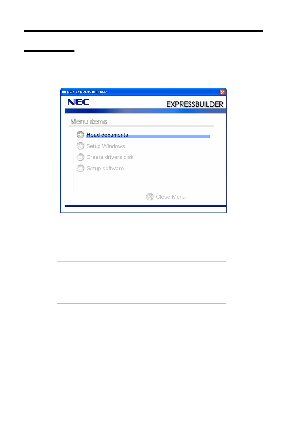
NEC EXPRESSBUILDER
The NEC EXPRESSBUILDER (referred to as "EXPRESSBUILDER" hereinafter) helps you install
the Operating system/the Management software or use the maintenance utilities.
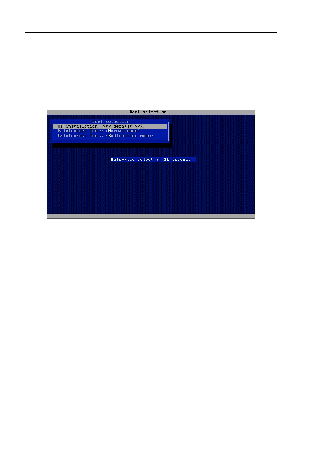
When you insert the EXPRESSBUILDER disk into the DVD drive and reboot the system, the
following menu appears.
Page 3
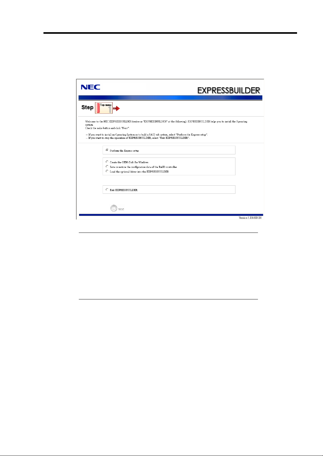
OS installation
If you select this item, the Top menu appears.
Installing and Using Utilities 6-3
IMPORTANT:
This tool is Configuration Tool that built on Windows PE 2.0
technology.
Pay attention to the automatic reboot that occurs after 72 hours
from start.
The configuration with Windows PE 2.0 supports Windows Server
2003 (32bit) and Windows Vista Business (32-bit (x86)), but the
other operation is not supported.
You can use the Express Setup (see Chapter 5) or the following functions from this menu.
– Create the OEM-Disk
You can create the Windows OEM-Disk to use at the Windows manual setup.
– Load the driver
This function is not usually used. If you add the new device to the server, this function
may use. (See Chapter 5.)
Page 4
6-4 Installing and Using Utilities
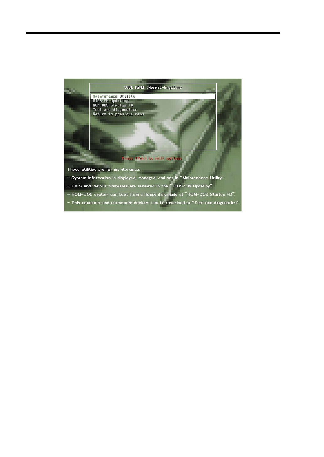
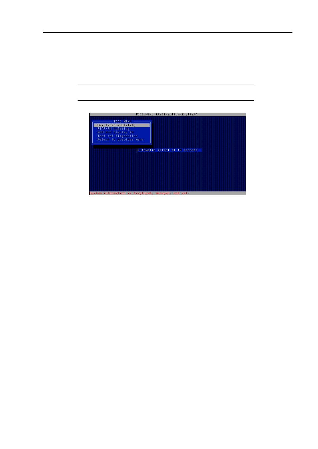
Maintenance Tools (Normal Mode)
If you select this item, the Tool menu appears.
You can use the below functions for maintenance.
– Maintenance Utility
The Maintenance Utility is usually used by the service representative. (See Chapter 7.)
– BIOS/FW Updating
You can update the system BIOS by using the floppy disk (prepare a 3.5" floppy disk).
– ROM-DOS Startup FD
The ROM-DOS Startup FD is used for starting the ROM-DOS system.
– Test and diagnostics
This function allows you to diagnose this computer. (See Chapter 7.)
Page 5
Installing and Using Utilities 6-5
Maintenance Tools (Redirection Mode)
If you want to operate this computer via the BIOS redirection (the console-less function),
select this item.
NOTE: If you operate this computer via the Remote KVM function,
select the "Maintenance Tools (Normal mode)".
The menu's functions are the same as the "Maintenance Tools (Normal Mode)".
Page 6
6-6 Installing and Using Utilities
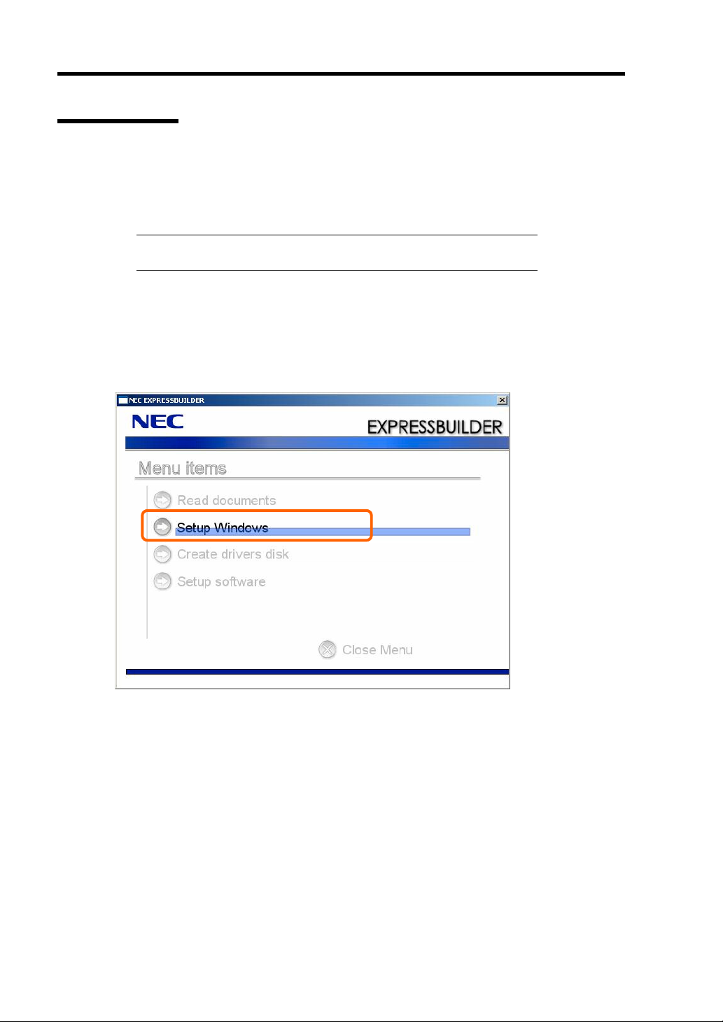
Autorun Menu
When the EXPRESSBUILDER disk is inserted into the DVD drive, Windows automatically
launches the menu as shown below.
This menu is used to,
Read the User's Guide or the other documents,
Update the server system (Windows drivers), and
Install the management software.
NOTES:
This menu requires Microsoft Windows XP, Vista or Windows
Server 2003 (or later).
Some documents are provided in PDF format. Use the Adobe
Reader to view or print these documents.
If the menu does not appear, select "My computer" by using the Explorer, and double-click the icon
of the DVD drive that contains the EXPRESSBUILDER DVD.
Some menu items are grayed-out when the logon user does not have the authority of the
administrator or the menu item is not available for your system.
To use the menu,
Click on the menu items, or
Click the right mouse button on the menu window.
Page 7

Installing and Using Utilities 6-7
PARAMETER FILE CREATOR
"Parameter File Creator" is a tool to create [Parameter file] that is used for configuring the server
with the Express Setup (see Chapter 5 for details).
If you use the Parameter file created by the Express Setup and Parameter File Creator to operate the
setup, you can setup from the installation of OS to several utilities automatically except for a few
key input to confirm the specification. Also, you can install the system with the same specification
as before when re-installing the system. We recommend you to create [Parameter file] to setup the
servers from NEC EXPRESSBUILDER.
When using a floppy disk, a USB floppy disk drive is required.
IMPORTANT: You can not create [Parameter file] for Microsoft
Windows Server 2003 x64 Editions.
NOTE: You can install Windows Server 2003 without [Parameter file].
Also, you can modify/newly create [Parameter file] during the setup
with NEC EXPRESSBUILDER.
Page 8
6-8 Installing and Using Utilities
Parameter File
This section describes about specifying setup information that is necessary for OS installation and
creating [Parameter file].
Follow the procedure below.
IMPORTANT: Do not remove NEC EXPRESSBUILDER DVD from
drive during a parameter file creation.
1. Start the OS.
2. Insert the NEC EXPRESSBUILDER DVD into the optical disk drive.
The menu will appear.
3. Right-click on the screen or left-click [Setup Windows]. The menu will appear.
Page 9
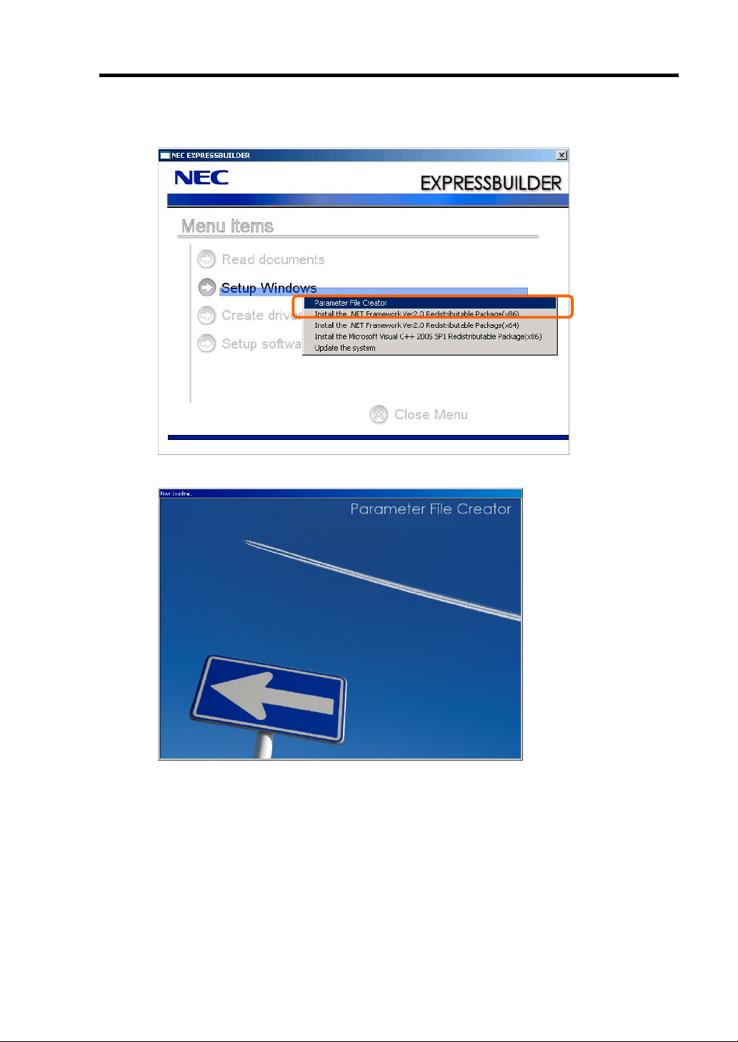
4. Click [Parameter File Creator].
Parameter File Creator will appear.
Installing and Using Utilities 6-9
Page 10
6-10 Installing and Using Utilities
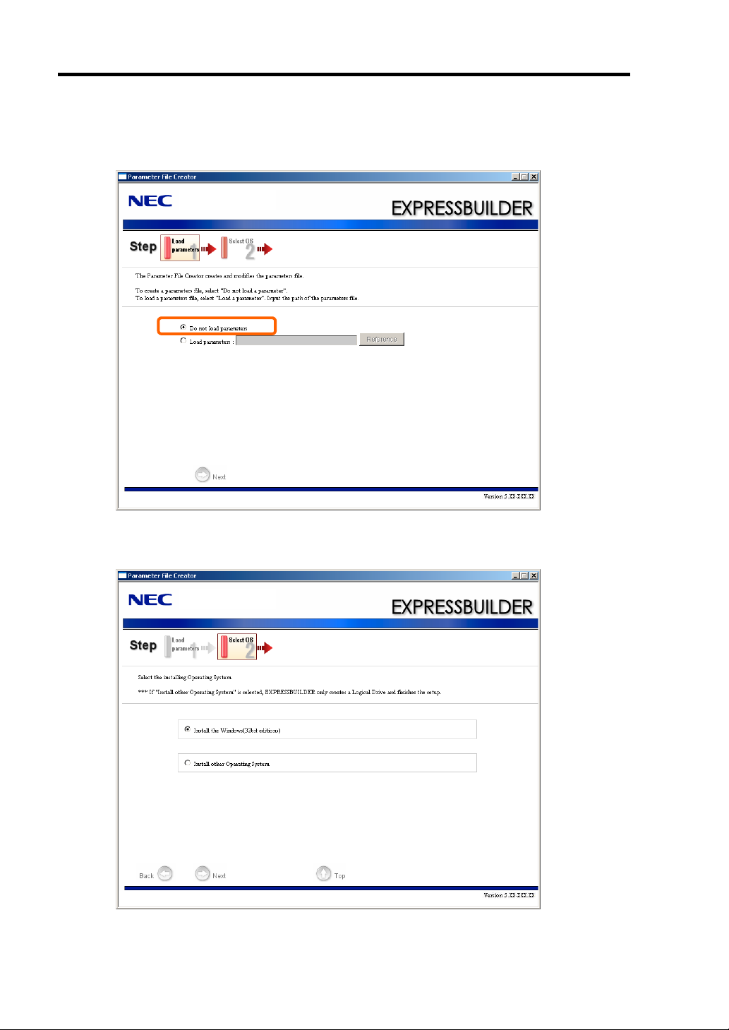
5. [Load Parameters] step is displayed.
Select [Do not load parameters] from the menu, click [Next].
6. Select the installing Operating System.
Select [Install the Windows (32bit editions)] from the menu, click [Next].
Page 11

Installing and Using Utilities 6-11
7. Enter the setting of a logical drive.
[Enter RAID setting] steps are displayed. Confirm the parameters, modify if necessary,
and then click [Next].
IMPORTANT: At "The number of the total physical devices",
Parameter File Creator displays upper limit that the RAID controller
can support.
The total of "The number of physical devices used to create the logical
drive" and "The number of the physical devices specified as the hot
spare" must not exceed "The number of the total physical devices"
which connected to the target system.
NOTE: You can use only the physical devices that have same model
number to configure logical drive.
Page 12
6-12 Installing and Using Utilities
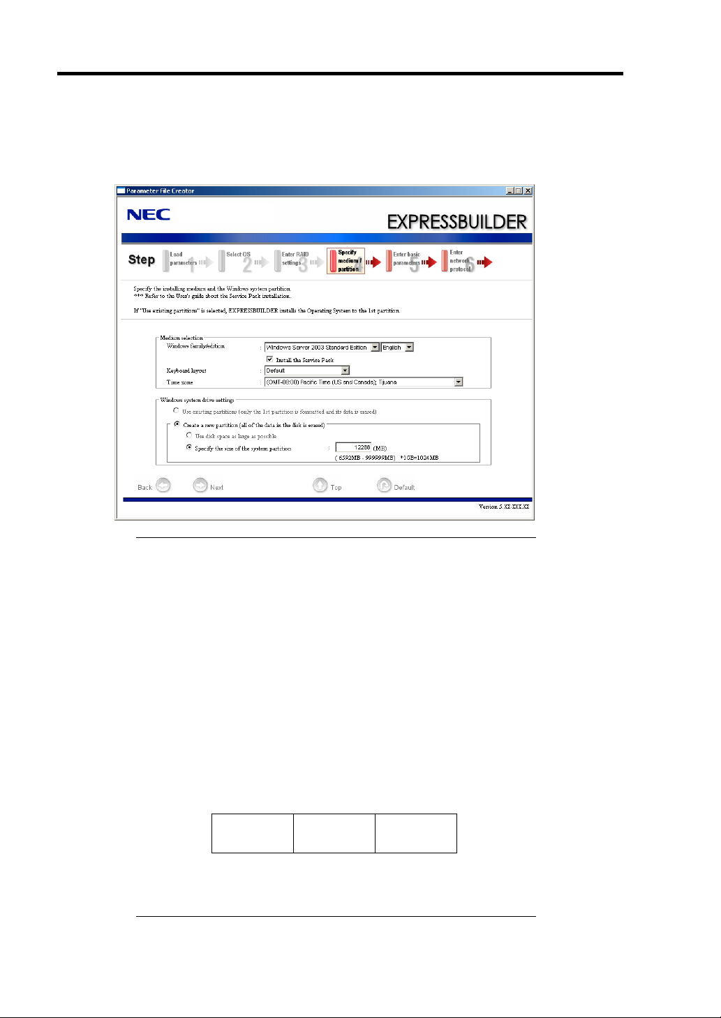
8. Specify the installing medium and the Windows system partition.
[Specify medium / Partition] steps are displayed. Confirm the parameters, modify if
necessary, and then click [Next].
IMPORTANT:
About partition size
– Specify the partition size larger than required minimum size for
OS installation.
– Do not specify larger partition size than the capacity of
connected hard disk drive.
– You can not specify the partition size larger than 2,097,152MB
(2TB) at RAID system.
If you select "Create a new partition" at "Windows system drive
settings", the contents of the hard disk will be all deleted.
If "Use existing partitions" is selected, EXPRESSBUILDER
installs the Operating System to the 1st partition (1st partition is
deleted). The data in the other partition is kept if the system has
two or more partitions. (See the figure below.)
First
Partition
Deleted
You can not re-install the system with the existing partition that is
Second
Partition
Retained
Third
Partition
Retained
upgraded to Dynamic Disk remained. Do not select "Use existing
partitions" at "Windows system drive settings".
Page 13
Installing and Using Utilities 6-13
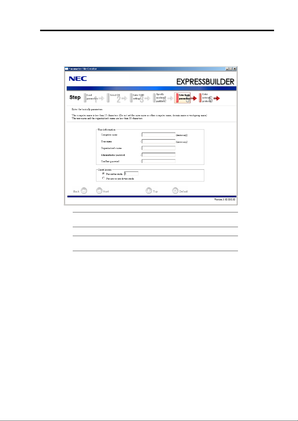
9. Enter the user information and client license mode. [Enter basic parameters] steps are
displayed. Confirm the parameters, modify if necessary, and then click [Next].
IMPORTANT: Computer name and User name are required
parameters.
NOTE: Even if you do not input value into "Administrator password",
"Confirm password", "zzzzzz" is displayed.
Page 14
6-14 Installing and Using Utilities
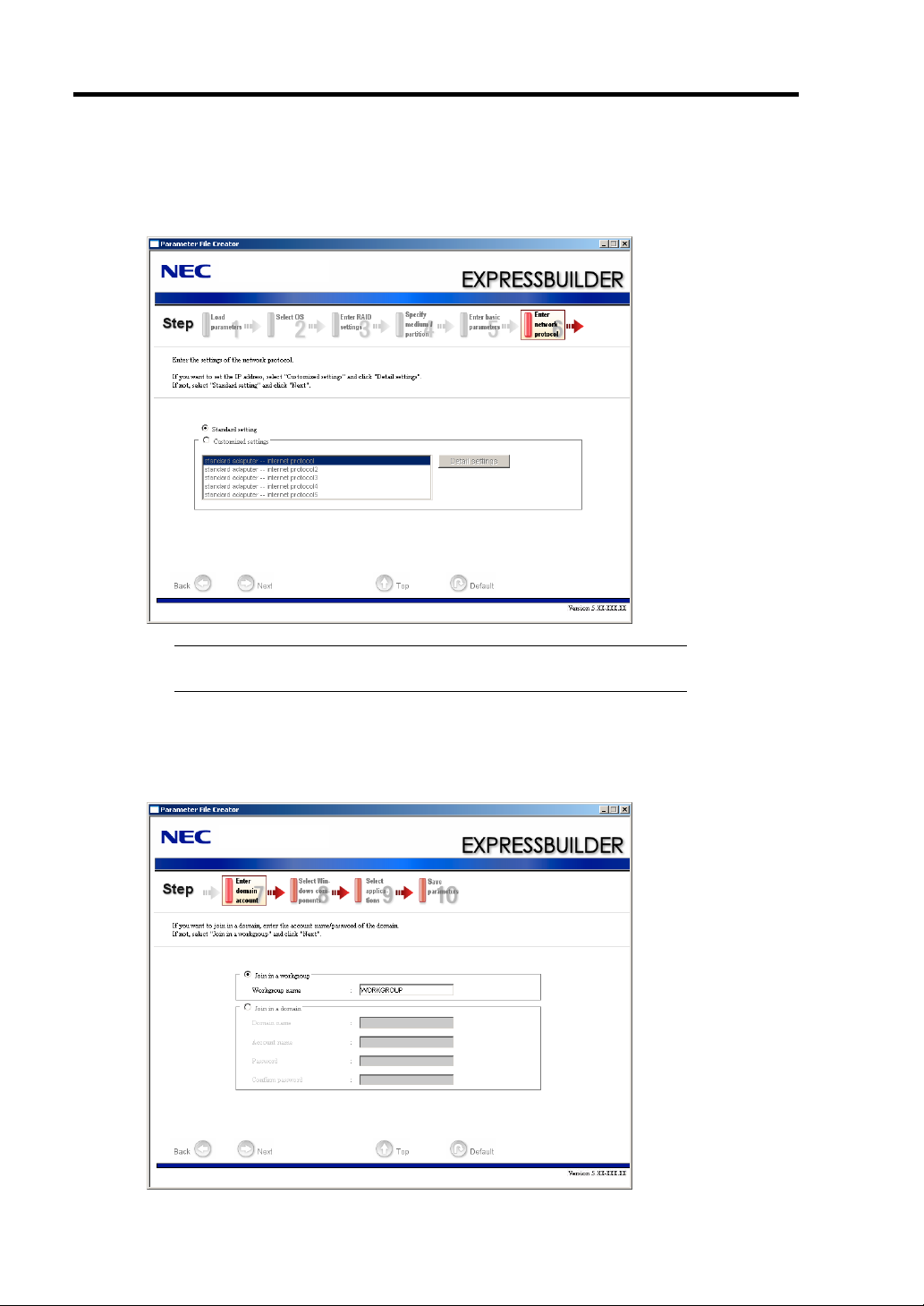
10. Enter the setting of the network protocol.
[Enter network protocol] steps are displayed. Confirm the parameters, modify if necessary,
and then click [Next].
NOTE: The order of entry in custom setting may differ from the
numbering of LAN port.
11. Enter the domain or workgroup name to be used.
[Enter domain account] steps are displayed. Confirm the parameters, modify if necessary,
and then click [Next].
Page 15
Installing and Using Utilities 6-15
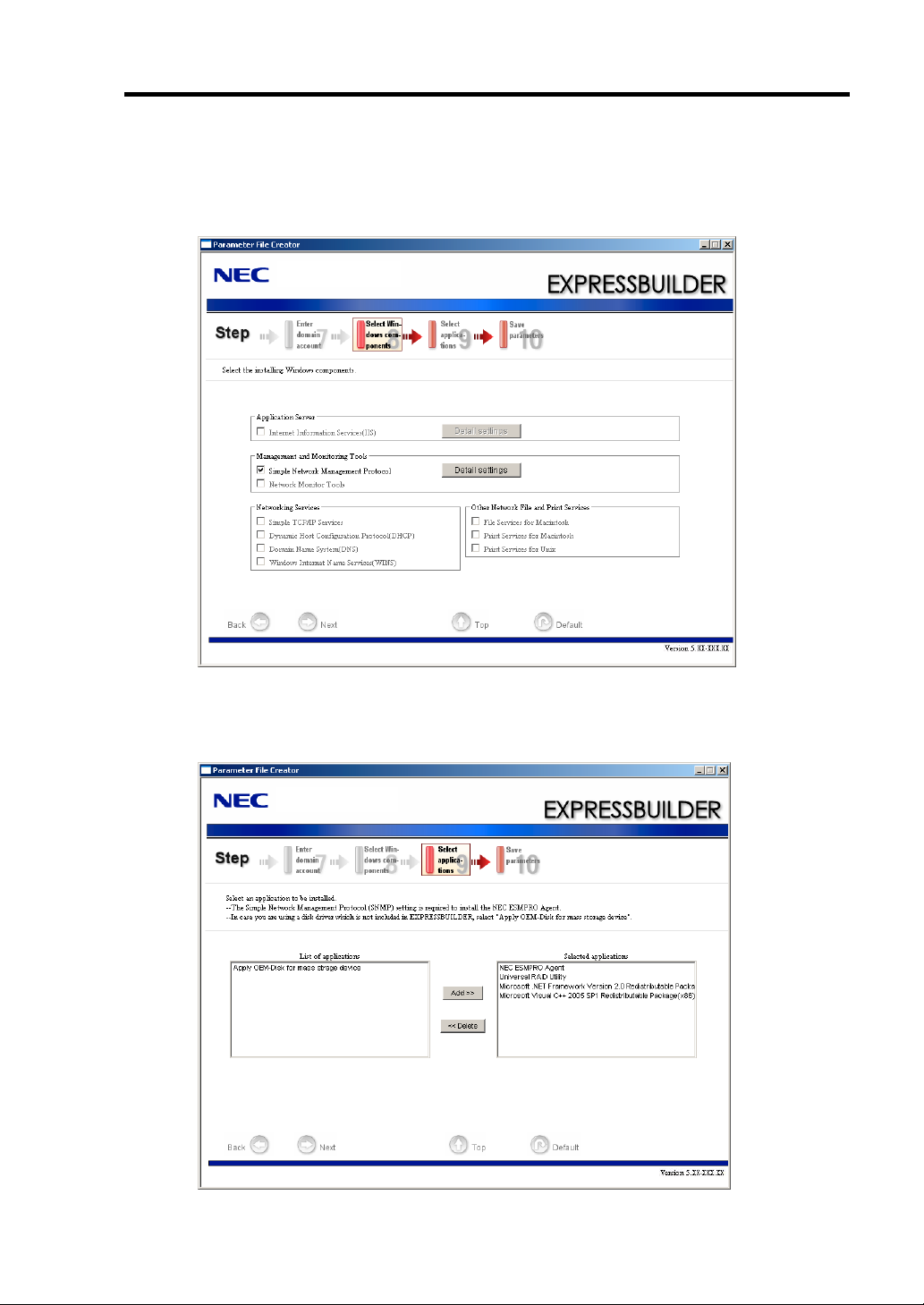
12. Select the installing components.
[Select Windows components] steps are displayed. Confirm the parameters, modify if
necessary, and then click [Next]
13. Select the installing applications.
[Select applications] steps are displayed. Confirm the parameters, modify if necessary, and
then click [Next].
Page 16
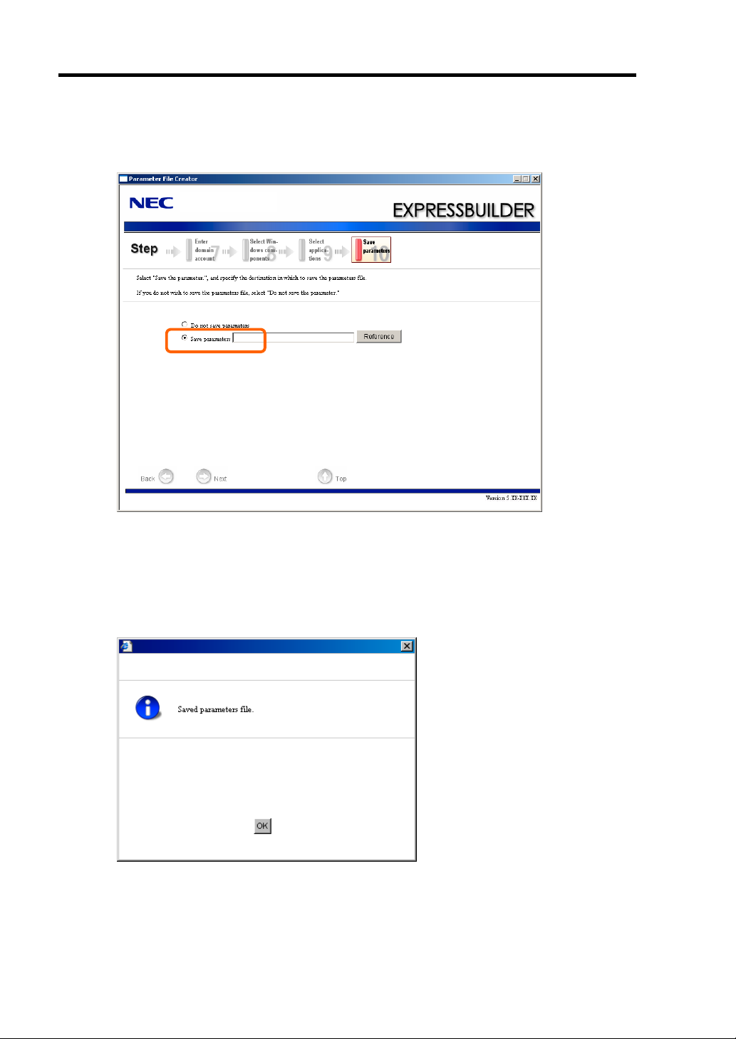
6-16 Installing and Using Utilities
14. Save the parameters.
[Save parameters] steps are displayed.
If you want to save the parameters, set the free formatted floppy disk.
Select [Save parameters], enter the file path of the parameters files into the text box and
click [Next].
If not, select [Do not save parameters].
15. Saved to a floppy disk.
Page 17
Installing and Using Utilities 6-17
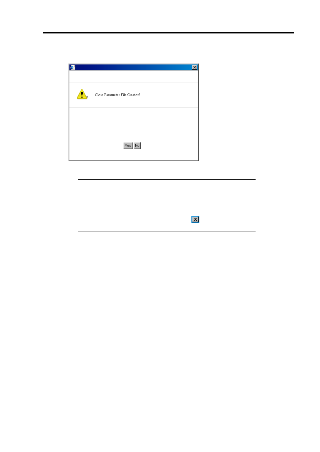
Now [the floppy disk containing the parameters file] has been created.
Click [Yes] to exit Parameter File Creator.
NOTES:
If you modify existing information file (parameter file), click
"Load Parameters" at [Load Parameters] screen. Refer to help to
modify information file.
If you cancel operation on the way, click at the upper-right
corner of the screen.
Page 18

6-18 Installing and Using Utilities
NEC ESMPRO
The NEC ESMPRO lets a system administrator manage remote servers across a network. NEC
ESMPRO monitors server hardware and software configurations, failures, and performance. With
log data collected by NEC ESMPRO, a system administrator can track long-term and short-term
performance, monitor server usage, create graphs to record trends, and check server failure rates.
The administrator can use the information collected to create more efficient data routing procedures
and optimize server usage.
Functions and Features
NEC ESMPRO offers many functions and features for managing remote servers across a network.
These features help the system administrator perform daily system operation, system extension, and
transfer tasks. Some features of NEC ESMPRO Manager include:
Hardware and software server configuration
– Hardware resources mounted in servers, such as the CPU, memory, disks, RAID
System, and LAN boards.
– Software resources, such as operating system information and drivers running on each
server.
Server failures
– On-screen real-time displays provide the system administrator with the failure type,
location, cause, and suggested corrective action.
– Failure data includes hardware failure information such as system board temperature,
memory failure, crashes, and software failure information.
Performance
– NEC ESMPRO monitors server performance and displays server usage on the screen
and displays information, such as the rate of CPU load, memory usage, disk usage, and
LAN traffic. Usage threshold values can help the system administrator monitor and
prevent server overloads.
For installation procedure and detailed explanations on NEC ESMPRO, refer to the online
document in the NEC EXPRESSBUILDER DVD.
Page 19
Installing and Using Utilities 6-19
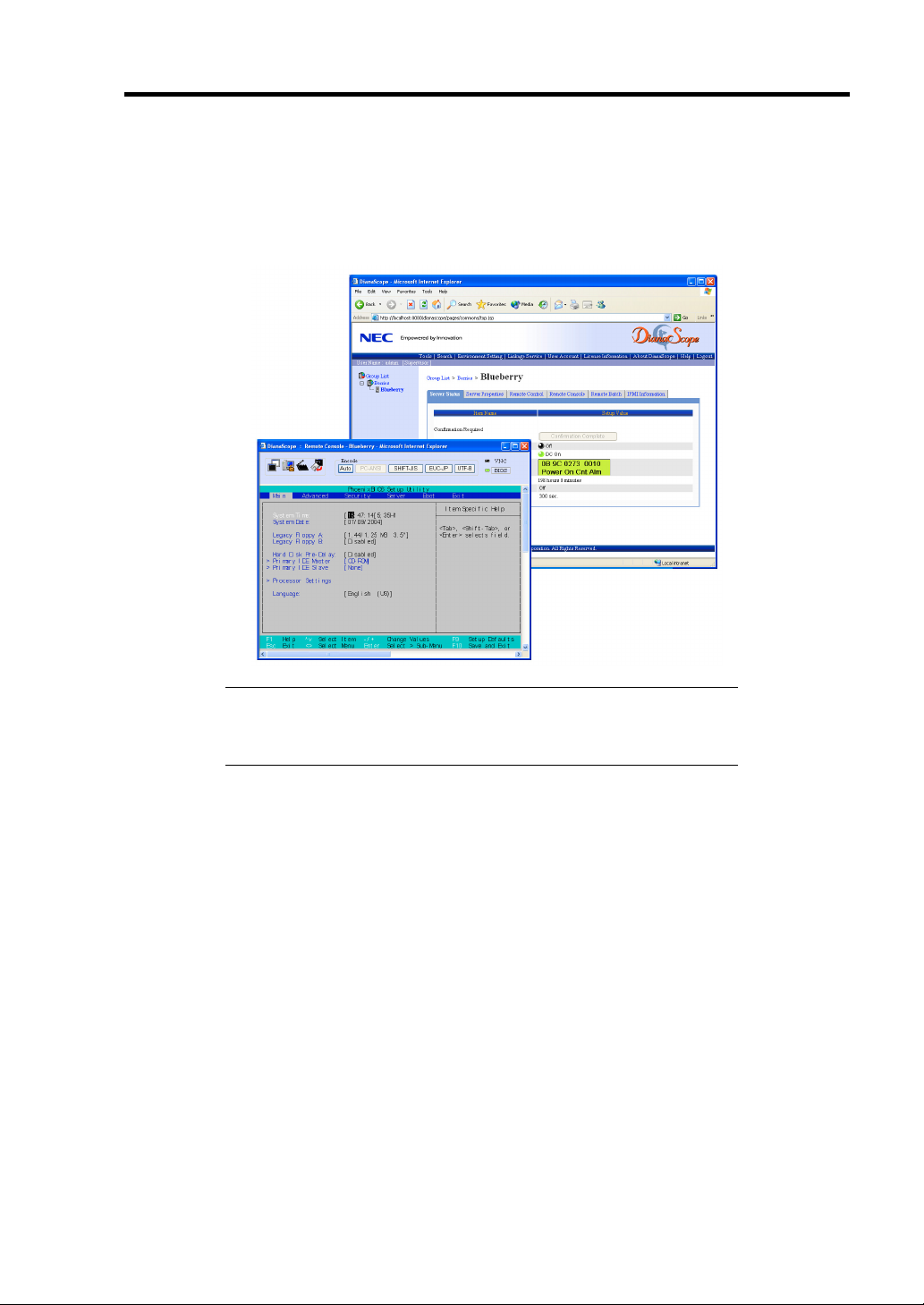
NEC DianaScope
NEC DianaScope is software for the remote management of the server.
See the online documents for details on the functions and installation of NEC DianaScope.
NOTE: You need the server license to activate DianaScope for this
product. The server license below is attached to this product.
DianaScope Additional Server License (1)
Page 20

6-20 Installing and Using Utilities
Universal RAID Utility
Universal RAID Utility is an application to manage or monitor the following RAID Controllers.
Internal RAID Controller (equivalent to N8103-116)
N8103-90 Disk Array Controller (External SAS HDD)
Before attempting to operate Universal RAID Utility, read the "Universal RAID Utility User's
Guide" included in NEC EXPRESSBUILDER DVD. The manual explains the installation
procedure and notes on operating Universal RAID Utility.
Setup with Express Setup
You can install Universal RAID Utility with Express Setup contained in NEC EXPRESSBUILDER
DVD. When you start the Express Setup, a dialog to specify an application appears. Select
[Universal RAID Utility] on the dialog.
Page 21

Installing and Using Utilities 6-21
Manual Setup
Windows
You can start the setup program of Universal RAID Utility from [Autorun Menu].
Click to [Setup Software] → [Universal RAID Utility] in [Autorun Menu].
You need to install the following software.
Microsoft .NET Framework 2.0
The Runtime component of the Microsoft Visual C++ 2005 SP1
You can install these software from [Autorun Menu] too.
Click [Setup Windows] → [Install the .NET Framework Ver 2.0 Redistributable Package (x86)] (If
CPU architecture is x64, [Install the .NET Framework Ver2.0 Redistributable Package (x64)]) in
[Autorun Menu] for the setup of Microsoft.NET Framework 2.0.
Click [Setup Windows] → [Install the Microsoft Visual C++ 2005 SP1 Redistributable Package
(x86)] (Use the x86 package whatever the CPU architecture may be.) for the setup of the Runtime
component of the Microsoft Visual C++ 2005 SP1.
Linux
You need to run the setup.sh in the install image of Universal RAID Utility
There is the install image of Universal RAID Utility in the following directory of
EXPRESSBUILDER.
/BBB/lnx/pp/uraidutl
The part of BBB is BBB of the medium number (5.AA-BBB.CC) of EXPRESSBUILDER
Page 22

6-22 Installing and Using Utilities
Using Universal RAID Utility via Network
Universal RAID Utility doesn't have the function of management to computer installed RAID
Controller via network. If you want to manage it via network, please use the function of remote
console (ex. Remote Desktop of Windows).
Creating Logical Drive of RAID 6
You must use four or larger Physical Devices for creating the Logical Drive of RAID 6 by Universal
RAID Utility. If you want to create the Logical Drive from three Physical Devices, you need to use
WebBIOS.
Page 23

Chapter 7
Maintenance
This chapter describes the daily maintenance of the server and precautions when relocating or
storing the server.
MAKING BACKUP COPIES
NEC recommends you make backup copies of your valuable data stored in hard disk drives of the
server on a regular basis. For backup storage devices suitable for the server and backup tools,
consult with your service representative.
When you have changed the hardware configuration or BIOS configuration, select "System
Information Management" and then "Save" of the Off-line Maintenance Utility to make a backup
copy of the system information.
Also make a backup copy of the RAID System configuration data if your system is in the RAID
System configuration. When your hard disk drives have been auto-rebuilt due to a failure, it is
recommended to make a backup copy of the configuration data. To make a backup copy of the
configuration data, use the configuration utility that is resident in the FLASH memory on the
optional RAID Controller. Refer to the manual supplied with the board.
Page 24
7-2 Maintenance
CLEANING
Clean the server on a regular basis to keep the server in a good shape.
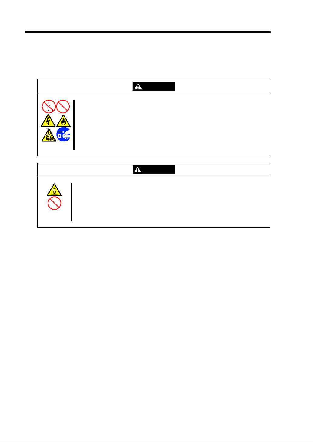
WARNING
Observe the following instructions to use the server safely. Failure to follow
these instructions may result in death or serious personal injury. See pages 13 to 1-8 for details.
Do not disassemble, repair, or alter the server.
Do not remove the lithium battery.
Disconnect the power plug before working with the server.
CAUTION
Observe the following instructions to use the server safely. Failure to follow
these instructions may cause a fire, personal injury, or property damage. See
pages 1-3 to 1-8 for details.
Avoid installation in extreme temperature conditions.
Make sure to complete board installation.
Page 25

Maintenance 7-3
Cleaning the Server
For daily cleaning, wipe the external surfaces of the server with a dry soft cloth. Follow the
procedure below if stains remain on the surfaces:
IMPORTANT:
To avoid altering the material and color of the server, do not use
volatile solvents such as thinner and benzene to clean the server.
The power receptacle, the cables, the connectors on the rear panel of
server, and the inside of the server must be kept dry. Do not moisten
them with water.
1. Make sure that the server is off-powered (the POWER/SLEEP LED goes off).
2. Unplug the power cord of the server from a power outlet.
3. Wipe off dust from the power cord plug with a dry cloth.
4. Soak a soft cloth in neutral detergent that is diluted with cold or lukewarm water, and
squeeze it firmly.
5. Rub off stains on the server with the cloth prepared in Step 4.
6. Soak a soft cloth in water, squeeze it firmly, wipe the server with it once again.
7. Wipe the server with a dry cloth.
8. Wipe off dust from the fan exhaust opening on the rear of the server with a dry cloth.
Page 26
7-4 Maintenance
Cleaning the Interior
One of the most important items in a good maintenance program is regular and thorough cleaning of
the interior of the server, especially around the mother board.
Dust buildup inside the server can lead to several problems. As dust acts as a thermal insulator, a
buildup can prevent proper system cooling. Excessive heat will shorten the life of server
components. Also, dust may contain conductive or corrosive materials that can cause short circuits
or corrosion of electrical contacts.
How often you should clean the interior of the server depends on the environment in which it is
located. For most office environments, you probably should clean the server every 12 months. For
more severe environments, clean the interior every 6 months.
Cleaning the interior of the server entails powering off the server and removing the left side cover.
You will need a small vacuum cleaner (with plastic tipped nozzle and electrostatic protection),
computer grade canned air, and a small brush for cleaning the interior.
Follow the procedure below to clean the interior of the server.
WARNING
Unplug all power cords.
Unplug all power cords before performing any maintenance. Voltage is present
inside the server and display unit even after the power is turned off. All voltage is
removed only when the power cord is unplugged.
1. Turn off the server and unplug all power cables.
2. Remove the logic cover and drive cover. (See Chapter 9.)
3. Use a small brush to loosen any dust and debris on the mother board.
4. Use computer grade canned air to blow dust off components on the mother board.
5. Use a small vacuum cleaner with plastic tip to vacuum out dust and debris from the
interior of the server.
6. Reinstall the covers. (See Chapter 9.)
7. Reconnect all power cables and turn on the server.
Page 27
Maintenance 7-5
Cleaning the Keyboard/Mouse
Make sure that the server and peripheral devices are all off-powered (the POWER/SLEEP LED
goes off), and then wipe the keyboard surface with a dry cloth.
The mouse operation depends on the degree of smoothness of the internal ball rotation. To keep the
mouse ball clean, use the mouse in a place with little dust. Follow the steps below to clean the
mouse regularly:
1. Prepare cold or lukewarm water, neutral detergent, alcohol, two dry soft clothes, and
cotton swabs.
2. Make sure that the server is off-powered (the POWER/SLEEP LED goes off).
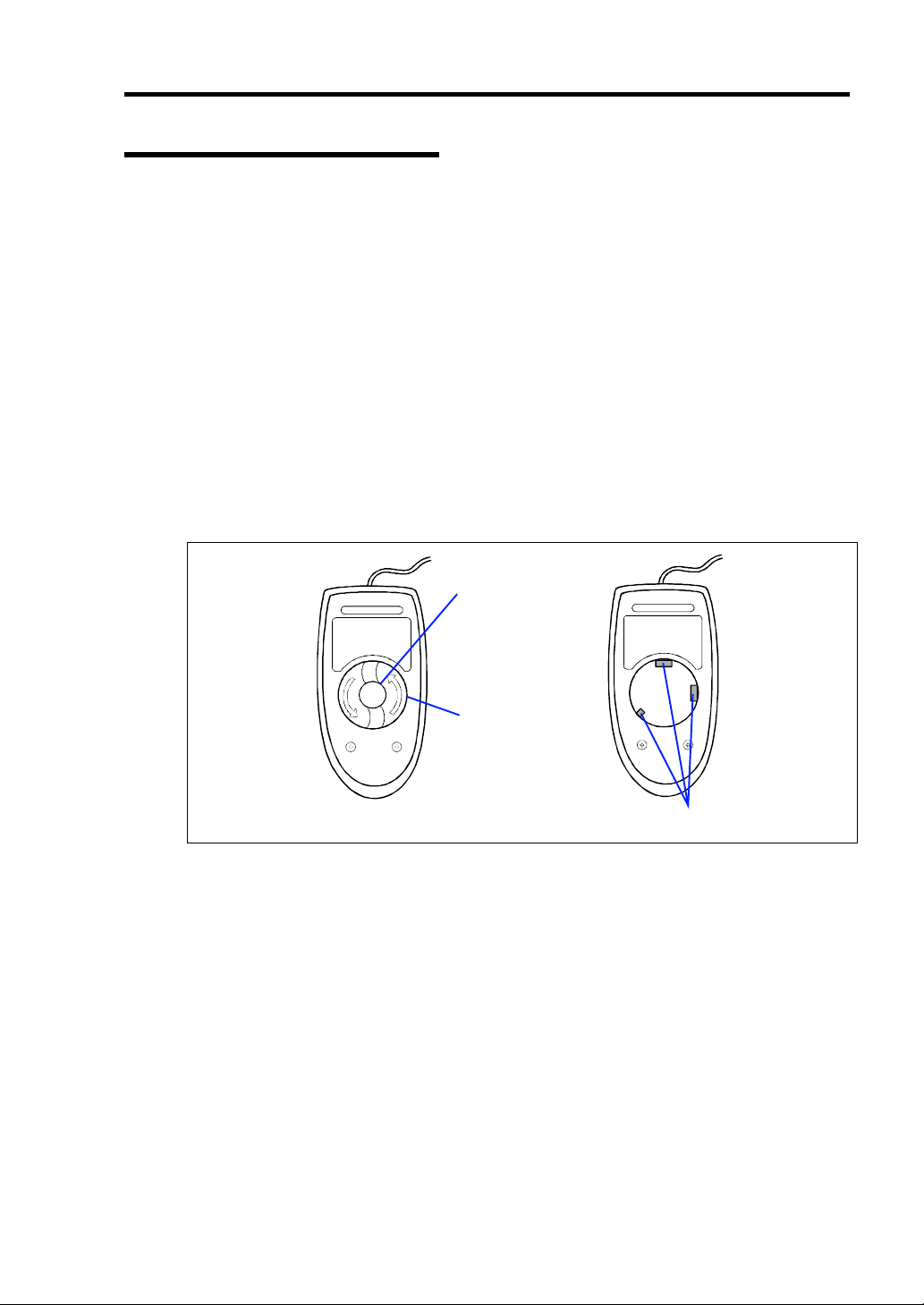
3. Turn the mouse upside down, and rotate the mouse ball cover counterclockwise to remove
it.
4. Take out the ball from the mouse. Cover the bottom of the mouse with your hand, and turn
your hand holding the mouse (the mouse is on your palm with the button upward). The
mouse ball is released onto your palm.
Mouse ball
Mouse ball cover
Bottom View
Roller
5. Soak a soft cloth in neutral detergent that is diluted with cold or lukewarm water, and
squeeze it firmly.
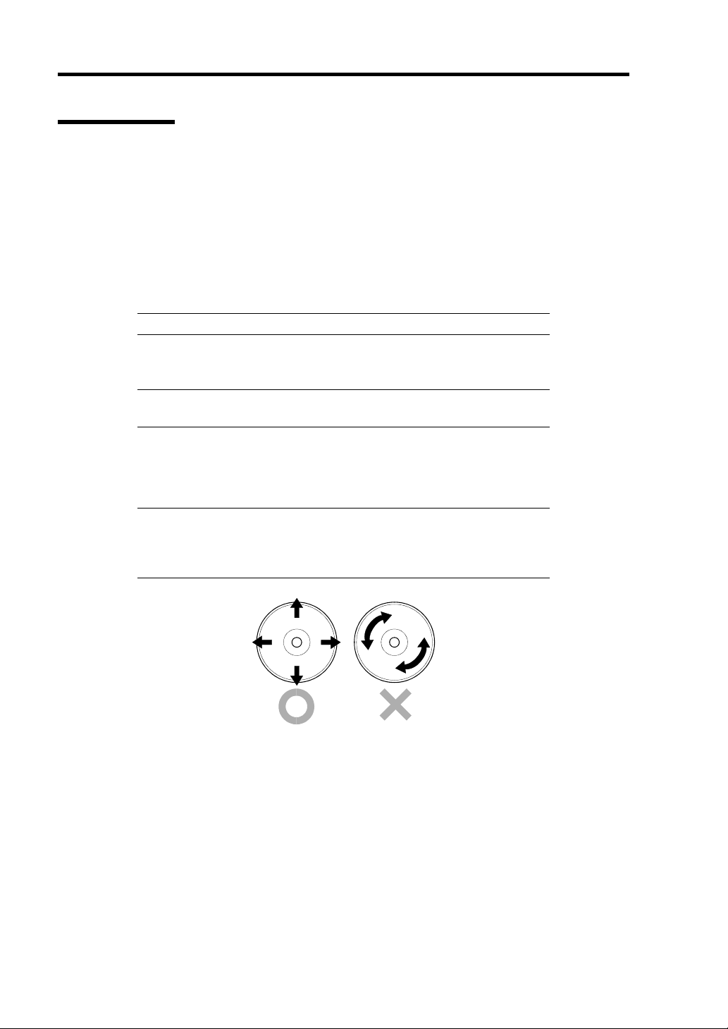
6. Rub off stains on the mouse ball. Softly wipe the mouse ball with the cloth prepared in
Step 5.
7. Wipe the mouse ball with a dry soft cloth.
8. Wipe three small rollers inside the mouse with a cotton swab soaked with alcohol. Wipe
stains slowly and carefully by rotating rollers with the tip of the cotton swab.
9. Blow out any dust from the mouse. Protect your eyes from the dust.
10. Put the mouse ball back into the mouse.
11. Place the mouse ball cover, and rotate it clockwise until it is locked.
Page 28
7-6 Maintenance
Cleaning Disc
A dusty disc or dust-accumulated tray causes the device to fail to read data correctly.
Follow the procedure below to clean the tray and disc regularly:
1. Make sure that the server is powered (the POWER/SLEEP LED is lit).
2. Press the CD tray Open/Close button on the front of the optical disk drive.
The tray opens.
3. Hold the disc lightly and take it out from the tray.
NOTE: Do not touch the signal side of the disc with your hand.
4. Wipe the tray with a dry soft cloth.
IMPORTANT: Do not wipe the lens of the optical disk drive. Doing
so may damage the lens and may cause a malfunction of the drive.
5. Push on the tray front to close the tray.
6. Wipe the signal side of the disc with a dry soft cloth.
IMPORTANT: Wipe disc from the center to the outside. Use only disc
cleaner if necessary. Cleaning a disc with record spray/cleaner, benzene,
or thinner causes damage to the disc contents. At worst, inserting the
disc into the server may cause failure.
Page 29

Maintenance 7-7
SYSTEM DIAGNOSTICS
The System Diagnostics runs several tests on the server.
Select [Maintenance Tools] - [Test and diagnostics] in the NEC EXPRESSBUILDER to diagnose
the system.
Test Items
The following items are tested in system diagnostics.
Memory
CPU cache memory
Hard disk drive used as a system
IMPORTANT: When executing the system diagnostics, make sure to
disconnect the LAN cable. Executing the system diagnostics with the
LAN cable connected, the network may be influenced.
NOTE: On checking the hard disk drive, no data is written into the
disk.
Page 30
7-8 Maintenance
Startup and Exit of System Diagnostics
There are two ways to diagnose the server: to use the local console (keyboard) of the server itself,
and to use the management PC via serial port (remote console).
IMPORTANT: Two methods of LAN and the serial port are mentioned
in "MAINTENANCE TOOLS" of Chapter 8 "Troubleshooting" in the
way of communicating in remote console.
Use the serial port to execute System Diagnostics with remote console.
The LAN connection is not for System Diagnostics.
Procedures to start the diagnostics program are as follows:
1. Shutdown the OS, and power off the server. Then, unplug the power cord.
2. Disconnect all the LAN cables from the server.
3. Plug the power cord and power on the server.
4. Use the NEC EXPRESSBUILDER DVD to start the system.
5. Select [Maintenance Tools (Normal mode)] when local console of the server is used for, or
select [Maintenance Tools (Redirection mode)] when remote console is used for.
NOTE: If the system displays the [Language selection] menu, select
[English].
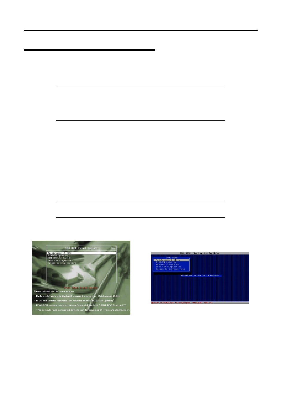
The following menu is displayed on the screen.
Local console Remote console
Page 31

Maintenance 7-9
T
T
6. Select [Test and diagnostics].
Select [End-User Mode] and the system diagnostics starts. The diagnostics will be
completed in approximately three minutes. When the diagnostics is completed, the screen
of the display changes as shown below:
Diagnostics tool title
eDoLi (TEst & Diagnosis On Linux) Ver001.00 (Build020901.1.1m)
Start 10:06:58 End 10:09:58 Pass 000:03:00 TestTime 000:03:00
est End : NormalEnd 03 AbnormalEnd 00 ForceEnd 00
<System>
MEM Memory 16 count NormalEnd
CACHE Cache 49 count NormalEnd
<SCSI>
HDD_02:000 DK32DJ-36W 89 count NormalEnd
[Enter] Detail Information [ESC] Return to Enduser Menu
Guide line
Test window title
Test End
Test result
Test summary
window
– Diagnostics tool title
Shows the name and version of the diagnostic tool.
– Test window title
Shows the progress of the diagnostics. "Test End" is displayed when the diagnostics
completes.
– Test result
Shows the start, end, and elapsed time and completion status of the diagnostics.
– Guide line
Shows the details of the keys to operate window.
– Test summary window
Shows the results of each test that executed the diagnostics. Move the cursor and
press the Enter key on the cursor line to display the details of the test.
When an error is detected by the system diagnostics, the relevant test result in the test
Summary window is highlighted in red, and "Abnormal End" is displayed in the result on
the right side.
Move the cursor to the test that detected the error, and press the Enter key. Record the
error message that has been output to the Detail Information screen and contact your
service representative.
Page 32

7-10 Maintenance
7. Follow the guide line shown at the bottom of the screen, and press the Esc key.
The [Enduser Menu] below is displayed.
TeDoLi (TEst & Diagnosis On Linux) Ver001.00 (Build020901.1.1m)
Enduser Menu
Enduser Menu
<Test Result>
<Device List>
<Log Info>
<Option>
<Reboot>
Please choose a function by the arrow key and push Enter key.
<Test Result> Shows the diagnostics completion screen of the above diagnostics.
<Device List> Shows a list of connected devices.
<Log Info> Shows the log information of the diagnostics. It can be saved on a floppy
disk.
To save it on a floppy disk, insert a formatted floppy disk to the floppy
disk drive, and select <Save(F)>.
<Option> Optional features can be used from this menu.
<Reboot> Reboots the system.
8. Select <Reboot> in the [Enduser Menu] above.
The server restarts and the system is started from the NEC EXPRESSBUILDER.
9. Exit the NEC EXPRESSBUILDER, and remove the DVD-ROM from the optical disk
drive.
10. Power off the server and unplug the power cord from the receptacle.
11. Reconnect all the LAN cables that have been disconnected in Step 2 to the server.
12. Plug in the power cord.
This completes the system diagnostics.
Page 33

RELOCATING/STORING THE SERVER
Follow the procedure below to relocate or store the server:
CAUTION
Observe the following instructions to use the server safely. Failure to follow
these instructions may cause a fire, personal injury, or property damage. See
pages 1-3 to 1-8 for details.
Never attempt to lift the server only by yourself.
Do not install the server in any place other than specified.
Do not connect/disconnect any interface cable with the power cord of the
server plugged to a power source.
IMPORTANT:
If the server needs to be relocated/stored due to a change in the floor
layout to a great extent, contact the service representative.
Maintenance 7-11
Make sure to make a backup copy of your valuable data in the hard
disk drive, if any.
Make sure not to apply a shock to hard disk drives to relocated the
server if the contains any.
1. Take a media out of the server, if any.
2. Power off the server (the POWER/SLEEP LED goes off).
3. Unplug the power cord of the server from a power outlet.
4. Remove all the cables from the server.
5. Hold the server by its bottom with at least three persons to carry the server.
IMPORTANT: Do not hold the front door to lift the server. The front
door may be disengaged from the server, causing personal injury.
6. Protect the server with the shock-absorbing materials, and pack it securely.
Page 34

7-12 Maintenance
(This page is intentionally left blank.)
Page 35

Chapter 8
Troubleshooting
If your server does not operate as expected, read this chapter before assuming a failure.
NOTE: For provision against an unexpected failure, it is
recommended to install the maintenance utility, NEC ESMPRO, to the
server and client computers.
Page 36

8-2 Troubleshooting
SYSTEM VIEWERS
Monitor the occurrence of fault by NEC ESMPRO during the system operation.
Especially take note on whether any alert is reported to NEC ESMPRO Manager on the
management PC. Check whether any alert is reported on the Operation Window, DataViewer, or
AlertViewer of NEC ESMPRO Manager.
[Example]
NEC ESMPRO Manager
Page 37

Troubleshooting 8-3
LEDS
The server includes LEDs to indicate the server states by a variety of colors and display patterns on
the front panel, hard disk drive, and power supply.
Chapter 2 "Status Indicators" lists the LED displays and their meanings and the actions taken at
occurrences of failures.
ERROR MESSAGES
If an error occurs in the server, an error message appears on the display unit connected to the server.
Error Messages after Power-on
Powering on the server automatically starts the self-diagnostic program, POST (Power On SelfTest). When the POST detects any error, it displays an error message and its measure on the display
unit.
Follow the table below to troubleshoot such errors. However, even when there is no hardware
failure, use of the keyboard or mouse at the following timing causes the POST to assume a
keyboard controller error and stop processing.
Immediately after the server is powered
Immediately after the system is rebooted in response to a keyboard instruction
(simultaneous key entry of Ctrl + Alt + Delete)
Immediately after the system is rebooted in response to an OS instruction
During hardware initialization following restart of the POST
When the POST detects a hardware failure due to the above reason, restart the server once again. If
the same error message reappears, you may assume there is no hardware error. To ensure normal
operation of the server, however, make sure to follow the following restrictions.
Do not make any keyboard entry or use the mouse before the memory count appears on
the screen following the server power-on.
Do not make any keyboard entry or use the mouse before the start-up message of the SCSI
Configuration Utility appears on the screen following the server reboot.
IMPORTANT: Take a note on the on-screen message before
contacting your service representative. The alarm indication would be a
great help for maintenance.
Page 38

8-4 Troubleshooting
POST Error Messages
When POST detects an error, it displays an error message on the display unit screen. The following
table lists error messages and actions to take.
IMPORTANT: Take a note on the messages displayed before
consulting with your service representative. Alarm messages are useful
information for maintenance.
Error
code
0200 Failure Fixed Disk. Contact your service representative.
0210 Stuck Key. Disconnect the keyboard and connect it
0211 Keyboard error Disconnect the keyboard and connect it
0213 Keyboard locked - Unlock key switch.
0220
0230 System RAM Failed at offset.
0231 Shadow Ram Failed at offset.
0232 Extended RAM Failed at address line.
0250
0251
0252
0260 System timer error.
0270 Real time clock error.
0271 Check date and time setting.
0280
0281
02D0 System cache error - Cache disabled.
Error message Recommended Action
again.
again. If the error cannot be corrected,
contact your service representative.
Release the lock of the key switch. If the
error cannot be corrected in spite of the
release of the lock, contact your service
representative.
Monitor type does not match CMOS - Run
SETUP.
System battery is dead - Replace and run
SETUP.
System CMOS checksum bad - Default
configuration used.
Password checksum bad - Passwords
cleared.
Previous boot incomplete - Default
configuration used.
Memory size found by POST differed from
EISA CMOS.
Start the SETUP. If the error cannot be
corrected in spite of the start of SETUP,
contact your service representative.
Contact your service representative.
Contact your service representative to
replace the battery. (After restarting the
computer, start the SETUP to provide the
setting again.)
The default values have just been set. Start
the SETUP to provide the setting again. If
the error cannot be corrected, contact your
service representative.
The password has just been cleared. Start
the SETUP to provide the setting again.
Start the SETUP to set the date and time
again. If the same error occurs
successively in spite of the resetting,
contact your service representative.
Start the SETUP to provide the setting
again.
Initialize EISA CMOS.
The cache cannot be used. Contact your
service representative.
Page 39

Troubleshooting 8-5
Error
code
02D1 System Memory exceeds the CPU's caching
02F4 EISA CMOS not write able.
02F5 DMA Test Failed.
02F6 Software NMI Failed.
02F7 Fail-safe Timer NMI Failed.
0B22 Processors are installed out of order. Request the maintenance to replace the
0B28 Unsupported CPU detected on CPU socket
0B29 Unsupported CPU detected on CPU socket
0B30 FAN1 Alarm occurred.
0B31 FAN2 Alarm occurred.
0B32 FAN3 Alarm occurred.
0B33 FAN4 Alarm occurred.
0B34 FAN5 Alarm occurred.
0B35 FAN6 Alarm occurred.
0B36 FAN7 Alarm occurred.
0B37 FAN8 Alarm occurred.
0B42 Resource Conflict
0B43 Warning: IRQ not configured
0B45 System configuration Data Write Error
0B50 Processor #1 with error taken off line.
0B51 Processor #2 with error taken off line.
0B5F Forced to use Processor with error
0B60 DIMM group #1 has been disabled
0B61 DIMM group #2 has been disabled
0B62 DIMM group #3 has been disabled
0B63 DIMM group #4 has been disabled
0B64 DIMM group #5 has been disabled
0B65 DIMM group #6 has been disabled
0B70 The error occurred during temperature
0B71 System Temperature out of the range. Contact your service representative to
0B74 The error occurred during voltage sensor
0B75 System voltage out of the range.
0B80 BMC Memory Test Failed.
0B81 BMC Firmware Code Area CRC check failed.
0B82 BMC core Hardware failure.
0B83 BMC IBF or OBF check failed.
0B8A BMC SEL area full
0B8B BMC progress check timeout.
0B8C BMC command access failed.
0B8D Could not redirect the console - BMC Busy 0B8E Could not redirect the console - BMC Error -
Error message Recommended Action
Contact your service representative.
limit.
CPU.
Make sure that the server supports the
1.
2.
sensor reading.
reading.
CPU. If you are not sure, contact your
service representative to request the
maintenance.
Clean the internal cooling fans.
Contact your service representative to
replace the fan.
Contact your service representative.
Because an error is detected in every CPU,
the system is forcibly started. Contact your
service representative.
Contact your service representative.
Contact your service representative.
replace the fan.
Contact your service representative.
Turn off the power once and then on again
to start the server. If the error cannot be
corrected, contact your service
representative.
Clear the system event logs by using the
BIOS SETUP utility (see Chapter 4).
Turn off the power once and then on again
to start the server. If the error cannot be
corrected, contact your service
representative.
Page 40

8-6 Troubleshooting
Error
code
0B8F
0B90 BMC Platform Information Area corrupted.
0B91 BMC update firmware corrupted.
0B92 Internal Use Area of BMC FRU corrupted.
0B93 BMC SDR Repository empty.
0B94 IPMB signal lines do not respond.
0B95 BMC FRU device failure.
0B96 BMC SDR Repository failure.
0B97 BMC SEL device failure.
0B98 BMC RAM test error.
0B99 BMC Fatal hardware error.
0B9A BMC not responding.
0B9B Private I2C bus not responding.
0B9C BMC internal exception.
0B9D BMC A/D timeout error.
0B9E SDR repository corrupt.
0B9F SEL corrupt.
0BB0 SMBIOS – SROM data read error.
0BB1 SMBIOS – SROM data checksum bad.
8068 Unsupported Processor Speed detected on
8069 Unsupported Processor Speed detected on
8100 Memory Error detected in DIMM group #1.
8101 Memory Error detected in DIMM group #2.
8102 Memory Error detected in DIMM group #3.
8103 Memory Error detected in DIMM group #4.
8104 Memory Error detected in DIMM group #5.
8105 Memory Error detected in DIMM group #6.
8160 Mismatch Processor Type/Speed detected
8161 Mismatch Processor Type/Speed detected
Error message Recommended Action
Could not redirect the console - BMC
Parameter Error -
CPU Slot 1.
CPU Slot 2.
on Processor 1.
on Processor 2.
Turn off the power once and then on again
to start the server. If the error cannot be
corrected, contact your service
representative.
This is not a fatal error. Turn off the power
once and then on again to restart the
server. If the error cannot be corrected,
contact your service representative.
Turn off the power once and then on again
to restart the server. If the error cannot be
corrected, contact your service
representative.
This is not a fatal error. Turn off the power
once and then on again to restart the
server. If the error cannot be corrected,
contact your service representative.
This is not a fatal error. Turn off the power
once and then on again to restart the
server. If the error cannot be corrected,
contact your service representative.
Turn off the power once and then on again
to start the server. If the error cannot be
corrected, contact your service
representative.
Update the RMC firmware. If the error
cannot be corrected, contact your service
representative.
Turn off the power once and then on again
to start the server. If the error cannot be
corrected, contact your service
representative.
Contact your service representative.
Contact your service representative.
Contact your service representative to
replace the DIMM in the relevant group.
Contact your service representative.
Page 41

Troubleshooting 8-7
Error
code
None Expansion ROM not initialized – PCI Mass
Error message Recommended Action
Storage Controller in slot n (n: slot number)
H/W Configuration of BMC is corrupted.
!! Update BMC F/W Configuration by
configuration tool !!
!! Refer to BMC configuration manual !!
Disable initialization of the optional device
expansion ROM by using the BIOS SETUP
utility (see Chapter 4).
Use the NEC EXPRESSBUILDER to
configure the remote management card
(see Chapter 6).
Page 42

8-8 Troubleshooting
Beep Codes
If an error occurs during the POST, the server beeps, indicating the type of error.
Each number indicates the number of short beeps, and a hyphen indicates a pause. For example, the
beep interval 1-5-2-2 indicates 1 beep, pause, 2 beeps, pause, 2 beeps, pause, and 3 beeps notifying
that no processor is detected on the mother board.
Beep code Description Recommended action
1-2 Option ROM initialization
error
3-3
1-2-2-3
1-3-1-1 DRAM refresh test error 1. Check if the DIMM is properly installed.
1-3-1-3 Keyboard controller error 1. Check if the keyboard is properly connected.
1-3-3-1 No memory or capacity
1-3-4-1 DRAM address error
1-3-4-3 DRAM test Low Byte
1-4-1-1 DRAM test High Byte
1-5-1-1 CPU startup error
1-5-2-2 No CPU installed
1-5-4-2 AC power interrupted The AC power supply is interrupted due to power
1-5-4-4 Abnormal voltage Replace the mother board.
2-1-2-3 BIOS ROM copyright test
2-2-3-1 Unexpected interrupt test
ROM checksum error Replace the mother board.
check error
error
error
error
error
1. Check if the optional add-in card is properly
installed.
2. Run the BIOS SETUP utility to check the IRQ
assignment.
3. Ask your service representative to replace the addin card or mother board..
2. Remove the DIMM once, and then re-install it to
check if it operates normally.
3. Ask your service representative to replace the failed
DIMM or mother board.
2. Replace the mother board.
1. Check if the DIMM is properly installed.
2. Remove the DIMM once, and then re-install it to
check if it operates normally.
3. Ask your service representative to replace the failed
DIMM or mother board..
1. Check if the CPU is properly installed.
2. Remove the CPU once, and then re-install it to
check if it operates normally.
3. Ask your service representative to replace the failed
CPU.
failure or momentary voltage drop and the system is
restarted. This is not an error.
Replace the mother board.
Page 43

Troubleshooting 8-9
Error Messages on Virtual LCD
NEC EXPRESSSCOPE Engine 2 (Remote Management Controller) on your server board allows
you to monitor the server status on the WEB browser-based screen of the client PC via network.
The virtual LCD (16 digits x 2 lines) in the "Host Information" area displays the POST codes and
status message.
When POST detects an error, the POST error code is displayed on the virtual LCD upon completion
of POST. See the table for POST error codes for details.
Example:
Virtual LCD
Status i ndic ators
Message send from BIOS
Message send from B MC
POWER ON
ATTENTION
Messages displayed on upper line (BIOS message)
On-screen message Description Action
XX BIOS Rev YYYY
CPU Reconfigured
Mem Reconfigured POST completes with memory
POST in progress.
XX: POST code, YYYY: BIOS version
POST completes with processor
degraded.
degraded.
This is not an error.
Contact your service
representative.
Try the following steps to cancel
the error.
1. Start BIOS SETUP.
2. Select [Main] - Processor
Settings] - [Processor Retest] [Yes].
3. Select [Exit] - [Exit Saving
Changes].
Contact your service
representative.
Try the following steps to cancel
the error.
1. Start BIOS SETUP.
2. Select [Advanced] - [Memory
Configuration] - [Memory
Retest] - [Yes].
3. Select [Exit] - [Exit Saving
Changes].
Page 44

8-10 Troubleshooting
On-screen message Description Action
Memory C-Err XX A correctable error frequently occurs in DIMM
#XX.
Memory U-Err XX An uncorrectable error has occurred in DIMM
#XX.
PCI Bus PERR XX A PERR has occurred in the PCI bus XX.
PCI Bus SERR XX A SERR has occurred in the PCI bus XX.
Mem Err Disable A correctable memory error frequently
occurred.
Prepare To Boot POST completes normally. This is not an error.
Contact your service
representative.
Messages displayed on lower line (BMC message)
When the following messages are displayed on the virtual LCD, restart your server by turning off
and on. If an error still occurred, contact your service representative for maintenance.
On-screen message Description
240VA Power Down Power supply failure occurred.
BB +1.5v Alm XX
BB +1.8v Alm XX
BB +3.3v Alm XX
BB +5.0v Alm XX
BB +12v Alm XX
BB P_Vtt Alm XX
BB Temp1 Alm XX Mother board thermal error occurred.
DUMP Request ! Dump switch is pressed.
OS shutdown Alm OS shutdown alarm occurred.
Power On Cnt Alm Power supply failure occurred.
Power Unit 1 Alm Power unit #1 Failure occurred.
Power Unit 2 Alm Power unit #2 Failure occurred.
Proc Missing Processor is not found.
Proc 1 T-Trip
Proc 2 T-Trip
Proc1 Therm % XX
Proc2 Therm % XX
Proc1 VccpAlm XX
Proc2 VccpAlm XX
Processor 1 IERR
Processor 2 IERR
SMI timeout SMI timeout occurred.
Voltage alarm occurred on the mother board.
XX=09: high voltage (fetal)
XX=07: high voltage (warning)
XX=02: low voltage (warning)
XX=00: low voltage (fetal)
XX=09: high voltage (fetal)
XX=07: high voltage (warning)
XX=02: low voltage (warning)
XX=00: low voltage (fetal)
Thermal Trip occurred on processor #1 or #2. The system is forcibly
turned off.
Processor #1 or #2 thermal error occurred.
XX=09: high temperature (fetal)
XX=07: high temperature (warning)
XX=02: low temperature (warning)
XX=00: low temperature (fetal)
Voltage alarm occurred on processor #1 or #2.
XX=09: high voltage (fetal)
XX=07: high voltage (warning)
XX=02: low voltage (warning)
XX=00: low voltage (fetal)
IERR occurred on processor #1 or #2.
Page 45

On-screen message Description
Sys Fan 1 Alarm FAN#1 alarm occurred.
Sys Fan 2 Alarm FAN#2 alarm occurred.
Sys Fan 3 Alarm FAN#3 alarm occurred.
Sys Fan 4 Alarm FAN#4 alarm occurred.
Sys Fan 5 Alarm FAN#5 alarm occurred.
Sys Fan 6 Alarm FAN#6 alarm occurred.
Sys Fan 7 Alarm FAN#7 alarm occurred.
Sys Fan 8 Alarm FAN#8 alarm occurred.
VBAT Alm XX Voltage alarm in lithium battery occurred.
XX=09: high voltage (fetal)
XX=07: high voltage (warning)
XX=02: low voltage (warning)
XX=00: low voltage (fetal)
WDT timeout Watchdog timer timeout error occurred.
Troubleshooting 8-11
Page 46

8-12 Troubleshooting
SOLVING PROBLEMS
When the server fails to operate as expected, see the following to find out your problem and follow
the instruction given before asking for repair.
If the server still fails to operate successfully after solving your problem, take a note on the onscreen message and contact your service representative.
Problems with the Server
Fail to power on the server:
T Is the server is properly supplied with power?
→ Check if the power cord is connected to a power outlet (or UPS) that meets the
power specifications for the server.
→ Make sure to use the power cord provided with the server. Check the power cord
for broken shield or bent plugs.
→ Make sure the power breaker for the connected power outlet is on.
→ If the power cord is plugged to a UPS, make sure the UPS is powered and it
outputs power. See the manual that comes with the UPS for details.
Power supply to the server may be linked with the connected UPS using the BIOS
setup utility of the server.
<Menu to check: [Server] - [AC-LINK]>
T Did you press the POWER switch?
→ Press the POWER switch on the front of the server to turn on the power (the
POWER LED lights).
Fail to power off the server:
T Is the POWER switch enabled?
→ Restart the server and start the BIOS setup utility.
<Menu to check: [Security] - [Power Switch Inhibit]>
T Is the server running in the Secure Mode?
→ The POWER switch is disabled in the Secure Mode. (Forced shutdown is also not
available.) To release the Secure Mode, enter the password specified with the
BIOS SETUP utility.
Page 47

No screen display appears with beep:
→ Check whether DIMMs are connected to the mating connectors firmly.
→ Check whether DIMMs of different specifications are installed in the specific bank.
See Chapter 9 for the specifications of DIMMs.
→ DIMMs must be populated in pairs and in the following order:
11 and 21, 31 and 41, 12 and 22, 32 and 42, 13 and 23, and 33 and 43.
→ Installed DIMMs must be the same speed and must all be registered.
→ Take a note of beep code pattern, and take appropriate action according to the table
listed earlier in "Beep Codes".
POST fails to complete:
T Is the DIMM board installed?
→ At least two DIMM boards are required for operation.
→ DIMMs must be populated in pairs and in the following order:
11 and 21, 31 and 41, 12 and 22, 32 and 42, 13 and 23, and 33 and 43.
Troubleshooting 8-13
→ Installed DIMMs must be the same speed and must all be registered.
T Is the memory size large?
→ The memory check may take a few seconds if the memory size is large. Wait for a
while.
T Did you perform any keyboard or mouse operation immediately after you started the
server?
→ If you perform any keyboard or mouse operation immediately after start-up, POST
may accidentally detect a keyboard controller error and stops proceeding. In such
a case, restart the server once again. Do not perform any keyboard or mouse
operation until the BIOS start-up message appears when you restart the server.
T Does the server have contains appropriate memory boards or PCI devices?
→ Operation of the server with unauthorized devices is not guaranteed.
Page 48

8-14 Troubleshooting
Fail to access to internal or external devices (or such devices fail to operate):
T Are cables properly connected?
→ Make sure that the interface cables and power cord are properly connected. Also
make sure that the cables are connected in the correct order.
T Is the power-on order correct?
→ When the server has any external devices connected, power on the external
devices first, then the server.
T Did you install drivers for connected optional devices?
→ Some optional devices require specific device drivers. Refer to the manual that
comes with the device to install its driver.
T Is BIOS configuration correct?
→ When the server has PCI devices connected, make sure to set the PCI device
interrupt and others with the BIOS SETUP utility of the server. (Most PCI devices
generally do not require any change to the configuration, but some boards do
require specific settings. Refer to the manual that comes with the board for details
to make correct settings.
<Menus to check: [Advanced] - [PCI Configuration] - [PCI Slot xx ROM]
x: PCI slot number>
→ Some devices connected to the serial or parallel port may require I/O port address
or operation mode settings. Refer to the manual that comes with the board for
details to make correct settings.
<Menu to check: [Advanced] - [Peripheral Configuration]>
The POWER switch and sleep feature are disabled:
T Is the POWER switch masked by the BIOS feature?
→ The BIOS can disable power-off with the POWER switch after the operating
system is started (including shutdown by pressing the POWER switch for at least
four seconds).
Run the BIOS SETUP utility to change settings (see Chapter 4).
Page 49

The keyboard or mouse fails to operate:
T Is the cable properly connected?
→ You must use the provided keyboard/mouse branch cable (Y cable) for this server.
Make sure that the provided cable is connected to the correct connector on the rear
of the server.
→ The keyboard or mouse does not operate if it is connected when the server is
powered (not applicable to USB devices). Power of the server first and connect it
properly.
T Is BIOS configuration correct?
→ The keyboard and mouse may be disabled with the BIOS SETUP utility of the
server. Check the settings with the BIOS SETUP utility.
<Menus to check: [Advanced] - [Numlock]>
T Are the server drivers installed?
→ Refer to the manual that comes with your OS to check that the keyboard and
mouse drivers are installed. (These drivers are installed along with the OS.)
Some OS's allow you to change the keyboard and mouse settings. Refer to manual
that comes with your OS to check that the keyboard and mouse settings are
correct.
Troubleshooting 8-15
Fail to access to the disc:
T Is the disc properly set in the optical disk drive tray?
→ The tray is provided with a holder to secure the disc. Make sure that the disc is
placed properly in the holder.
T Is the disc applicable to the server?
→ The disc for Macintosh is not available for use.
T Is the CD/FDD bay installed correctly?
→ Reinstall the CD/FDD bay (see Chapter 9).
Inserted the correct disc but the message like the following is displayed:
The CD-ROM is not inserted or the wrong CD-ROM is inserted.
Please insert the correct CD-ROM.
OK
T Is the data side of the disc dirty or injured?
→ Take the disc out of the optical disk drive, confirm that it is not dirty or injured,
reset and click [OK].
Page 50

8-16 Troubleshooting
Fail to access the hard disk drive:
(Refer to the documentation supplied with the RAID Controller.)
T Is the hard disk drive applicable to the server?
→ Operation of any device that is not authorized by NEC is not guaranteed.
T Is the hard disk drive properly installed?
→ Make sure to lock the hard disk drive with the lever on its handle. The hard disk
drive is not connected to the internal connector when it is not completely installed
(see Chapter 9).
Fail to access the (internal or external) SCSI devices:
T Is the SCSI device applicable to the server?
→ Operation of any SCSI device that is not authorized by NEC is not guaranteed.
T Are SCSI devices properly configured?
→ When the server has external SCSI devices connected, hard disk drive settings,
including SCSI ID and terminator, are required. Refer to the manual that comes
with the SCSI device for details.
T Are the SCSI controllers (including optional controllers) properly configured?
→ Use the SCSI BIOS setup utility for proper configuration of SCSI devices
connected to the SCSI connector on the mother board. When the server has an
optional SCSI controller installed and SCSI devices connected to it, use the SCSI
BIOS setup utility that comes with the optional SCSI controller for proper
configuration. See the manual that comes with the optional SCSI controller for
details.
Page 51

The server is not found on the network:
T Is the LAN cable connected?
→ Make sure to connect the LAN cable to the network port on the rear of the server.
Also make sure that the LAN cable to use conforms with the network interface
standard.
T Is BIOS configuration correct?
→ The internal LAN controller may be disabled with the BIOS SETUP utility of the
server. Check the setting with the BIOS SETUP utility.
<Menus to check:
[Advanced] - [PCI Configuration] - [Onboard LAN] - [LAN Controller]>
T Have the protocol and service already configured?
→ Install the distinctive network driver for the server. Make sure that the protocol,
such as TCP/IP, and services are properly specified.
T Is the transfer speed correct?
→ Open the network property dialog box in control panel to specify the "Link Speed
& Duplex" value the same as the value specified for HUB.
Troubleshooting 8-17
Wake on LAN does not start from standby state.
T Is Hub set to Auto-Negotiation? Or, Is the client set to Auto-Negotiation/optimum
speed?
→ For both hub and client, Wake on LAN does not start from the standby state if the
speed is fixed to 1000Mbps.
Page 52

8-18 Troubleshooting
Event logs in using Intel Network adapter teaming
Event Type: Warning
Event Source: IANSMiniport
Event Category: None
Event ID: 11
Description: Adapter link down: Intel(R)PRO/1000 ----
Event Type: Warning
Event Source: IANSMiniport
Event Category: None
Event ID: 13
Description: Intel(R)PRO/1000 ---- has been deactivated from the team.
Event Type: Error
Event Source: IANSMiniport
Event Category: None
Event ID: 16
Description: Team #0: The last adapter has lost link.
Team network connection has been lost.
Event Type: Warning
Event Source: IANSMiniport
Event Category: None
Event ID: 22
Description: Primary Adapter does not sense any Probes:
Intel(R)PRO/1000 ---- Possible reason: partitioned Team.
Above-mentioned event log will appear when the system starts.
There is no problem in LAN driver operation.
Page 53

Troubleshooting 8-19
Problems with RAID System Configuration
Check the following if the server configuring a RAID System does not operate properly or a
management utility does not operate correctly. If a relevant item is found, follow the processing
method.
Fail to install the OS:
T Is the RAID Controller configured?
→ Provide proper configuration for the RAID Controller by using the WebBIOS.
Fail to start the OS:
T Is the BIOS of the RAID Controller changed?
→ Set the BIOS correctly by using the WebBIOS.
T Does POST recognize the RAID Controller?
→ After making sure that the RAID Controller is connected correctly, then power on
the server.
If the RAID Controller is not recognized correctly despite correct connection, the
RAID Controller may be failed. Contact your service representative.
Rebuild fails:
T Is the capacity of the hard disk drive to be rebuilt sufficient?
→ The hard disk drive to be rebuilt should have the same capacity of the failed had
disk drive.
T Is RAID0 configured?
→ RAID0 has no data redundancy, therefore, Rebuild is disabled in the RAID0
configuration. Replace the failed hard disk drive, create the configuration data
again and initialize the hard disk drives. Then recover the data by using backup
data.
Auto rebuild fails:
T Was a sufficient time taken for hot swap of hard disk drives?
→ To allow the auto rebuild to operate correctly, it should take 90 seconds or longer
for the interval between the removal of the failed hard disk drive and the
installation of a new hard disk drive.
A hard disk drive fails:
Contact your service representative.
Page 54

8-20 Troubleshooting
Problems with Windows
There are some cases that an event log is registered as follows when you install
Windows Server 2003 x64 Editions.
Source: DCOM
Category: Error
Event ID: 10016
Description: The application-specific permission settings do not grant Local Activation
permission for the COM server application with CLSID {555F3418-D99E4E51-800A-6E89CFD8B1D7} to the user {NT AUTHORITY\LOCAL
SERVICE} SID {S-1-5-19}.
This security permission can be modified using the component Services
administrative tool.
→ It is not a problem in operating the system.
There are some cases that an event log is registered as follows when you install
Windows Server 2003 x64 Editions.
Event Source: Service Control Manager
Event Type: Error
Event ID: 7011
Description: Timeout (30000 milliseconds) waiting for a transaction response from the
IMAP4Svc service.
→ When this event is not registered by rebooting the system, it is not a problem in
operating the system.
Page 55

Troubleshooting 8-21
There are some cases that an event log is registered as follows when you operate
Windows Server 2003 R2.
Source: IPMIDRV
Type: Error
Event ID: 1001
Description: The IPMI device driver attempted to determine if the system supported an IPMI BMC
device. The driver attempted to detect the presence of the IPMI BMC by searching the
SMBIOS for Type 38 record. But either no record was found or the record was not
compatible with the version of the device driver.
If a SMBIOS Type 38 record was detected, the Dump Data field of the event contains
a binary representation of the record.
→ If you use "Hardware Management" which is provided by Windows Server 2003
R2, above-shown event log will be registered.
For more details, refer to "Enabling Microsoft Windows Server 2003 R2
Hardware Management" on the following site.
[NEC Express5800 Web Site]
http://www.nec.co.jp/express/download/W2K3_R2
The system displays the message below and fails to log on.
Windows Product Activation
This copy of Windows must be activated with Microsoft before you can
continue. You cannot log on until you activate Windows.
To shut down the computer, click Cancel.
YES NO Cancel
→ In Windows Server 2003, the above message will be displayed if you use the
operating system without executing the license authentication. Select "Yes", and
execute the procedure for license authentication.
Cannot install the operating system correctly.
T Did you confirm the notes on installing the operating system?
→ See Chapter 6.
Page 56

8-22 Troubleshooting
Fail to start the OS with the /3GB switch
→ System often fails to start the OS with the /3GB switch.
In this case, please adjust the capacity of the user mode area using the /userva
switch in reference to the following URL.
http://support.microsoft.com/kb/316739/en
During installation, the following warning is registered in the System Log of the
Event Viewer:
Error detected on the device \Device\CdRom0
during the paging operation.
→ There is no problem on this issue.
Fail to start the OS:
T Is a floppy disk in the floppy disk drive?
→ Take out the floppy disk and restart the server.
T Is the NEC EXPRESSBUILDER DVD in the optical disk drive?
→ Take out the NEC EXPRESSBUILDER DVD and restart the server.
T Is the OS broken?
→ Use recovery process to recover the system.
The OS presents unstable operation:
T Did you update the system?
→ Installing a network drive after installation of the OS may cause unstable
operation. Use the NEC EXPRESSBUILDER DVD to update the system. (See
Chapter 6.)
The system does not restart automatically when a stop error occurs, though the
system is adjusted to automatically restarting:
→ When the system does not restart automatically, restart it manually.
The system restarts automatically when a stop error occurs, though the system is
NOT adjusted to automatically restarting:
→ There is no problem about this issue.
Check the System Event Log to confirm that STOP error occurred.
Page 57

Troubleshooting 8-23
Cannot turn the power OFF at the blue screen:
→ If you want to turn off the power at the blue screen, execute forced shutdown
(forced shutdown: continue to press POWER/SLEEP switch for 4 seconds). The
power will not be turned off if you press the switch for less than 3 seconds.
The PXE boot (network boot) fails or the server is not found on the network:
T Is the cable connected properly?
→ Connect the proper cable to the network port on the rear of the Express server. In
addition, make sure that the used cable conforms to the network interface standard.
T Is BIOS configuration correct?
→ The internal LAN controller may be disabled with the BIOS SETUP utility of the
server. Check the setting with the BIOS setup utility.
T Have the protocol and service already configured?
→ Install the distinctive network driver for the server. Make sure that the protocol,
such as TCP/IP, and services are properly specified.
T Is the transfer speed correct?
→ Open the network property dialog box in control panel to specify the link speed
and duplex value the same as the value specified for HUB.
The Telnet Service is not installed.
→ Adjust the computer name to 14 characters or less, and then install the Telnet Service
according to <How to install the Telnet Service>.
<How to install the Telnet Service>
1. Click [Run] on Start menu.
2. Type "tlntsvr /service" in the [Open] box, and click [OK].
3. Click Start menu, point to [Control Panel] and click [Computer Management] and then
click the [Services] to specify whether the Telnet Service is registered.
* When the installation of Telnet Service is finished, there is no problem if the computer
name is set to 15 characters or more.
Power ON/OFF (Wake On LAN) feature does not work:
→ Immediately after the AC power is turned on, the Remote Power ON/OFF feature
(Wake ON LAN) is disabled. Start Windows 2003 once, provide settings as shown
below, then shutdown the system. After restart, the Remote Power On/Off feature is
available unless the AC power is turned off.
Select [Start] → [Administrative Tools] → [Computer Management].
Select Device Manager, double-click [Intel(R) PRO/1000EB Network Connection
with I/O Acceleration #n] under Network Adapter, and specify as follows in [Detail]
tab.
PME: [ON]
Wake On: [Magic Packet]
Page 58

8-24 Troubleshooting
Problems with NEC EXPRESSBUILDER
When the server is not booted from the NEC EXPRESSBUILDER DVD, check the following:
T Did you set the NEC EXPRESSBUILDER during POST and restart the server?
→ If you do not set the NEC EXPRESSBUILDER during POST and restart the
server, an error message will appear or the OS will boot.
T Is BIOS configuration correct?
→ The boot device order may be specified with the BIOS SETUP utility of the server.
Use the BIOS SETUP utility to change the boot device order to boot the system
from the optical disk drive first.
<Menu to check: [Boot]>
If [OS installation ***default***] is selected at BOOT Selection screen, following message is
displayed.
After this message appears, check the error and take the appropriate corrective action according to
the message listed in the table below.
Message Cause
This EXPRESSBUILDER version was not designed
for this computer.
Insert the correct version and click [OK]. (When you
click [OK], the computer reboots.)
EXPRESSBUILDER could not get the hardware
parameters written in this motherboard.
This version is not designed for this computer or the
motherboard may be broken. (When you click [OK],
the computer reboots.)
The hardware parameters written in this
motherboard are incorrect.
This version is not designed for this computer or the
motherboard may be broken.
This NEC EXPRESSBUILDER
version is not designed for this server.
Execute the NEC EXPRESSBUILDER
on the compliant server.
This message is shown when NEC
EXPRESSBUILDER could not find
system-specific information because
of mother board exchange and so on.
Page 59

Troubleshooting 8-25
Problems with Express Setup
The system partition is created by size smaller than specified value.
→ In ExpressSetup, there are some cases that the system partition is created by size
about 8MB smaller than specified size.
It is not a problem in operating the system.
Following message appeared when you tried to install Express Setup to the hard disk drive
that has smaller capacity than the specified partition size:
The creating of the partition was failed.
The process can not be continued. The process was stopped.
OK
→ Cannot continue the setup.
Specify smaller partition size than the capacity of connected hard disk drive, and then
retry the setup.
Specified to join the Domain, but the system is installed as Workgroup.
→ When the setup fails to join the Domain during the installation, it will install the
system as Workgroup. Open [System] in Control Panel to specify joining the Domain.
Unable to specify the details of Network adapter.
→ In Express Setup, you can not specify the details of Network adapter. Specify them
from Control Panel after starting Windows.
Fail to start Parameter File Creator:
T Parameter File Creator requires to run by "Microsoft® HTML Application host".
→ If Parameter File Creator does not start, associate the file type with "Microsoft®
HTML Application host" via following process.
1) Click [Run] on Start menu.
2) Type "%windir%\system32\mshta.exe /register" in the [Open] box, and click
[OK].
Page 60

8-26 Troubleshooting
Problems with Windows Autorun Menu
Cannot read online document:
T Do you have Adobe Reader installed correctly in your system?
→ Some online documents are supplied with PDF format. To read the document of
PDF format, Adobe Reader is required in your system.
T Is the operating system Windows XP SP2?
→ With Windows XP SP2, the following information may appear in browser.
"To help protect your security, Internet Explorer has restricted this file from
showing active content that could access your computer. Click here for options..."
1. Click the Information Bar.
The shortcut menu appears.
2. Click [Allow blocked content].
The security alert dialog box appears.
3. Click [Yes] on dialog box.
The menu fails to appear:
T Is your system Windows XP or later, or Windows 2003 or later?
→ The Windows Autorun menu is supported by Windows XP/Windows 2003 or
later.
→ If your system runs on Windows Autorun Menu on Windows 2000 system, you
need to setup IE6.0 before using Windows Autorun Menu.
T Is Shift pressed?
→ Setting the DVD/CD-ROM with Shift pressed down cancels the Autorun feature.
T Is the system in the proper state?
→ The menu may not appear depending on the system registry setting or the timing
to set the DVD/CD-ROM. In such a case, start the Explorer and double-click the
icon of the optical disk drive.
Some menu items are grayed-out:
T Is your system environment correct?
→ The menu items are grayed-out when the logon user does not have the authority of
the Administrator or the system does not meet the requirements to install the
application. Login with the user having the proper authority on the proper system,
and try again.
Page 61

Troubleshooting 8-27
COLLECTING DR. WATSON DIAGNOSTIC INFORMATION
Dr. Watson collects diagnostic information related to application errors. The location to save the
information can be specified as you like. For more information, refer to Chapter 5.
MEMORY DUMP
If an error occurs, the dump file should be saved to acquire necessary information.
If you saved the dump to DAT, write down that it is saved as "NTBackup" or "ARCServe" on the
label. You can specify the location to save the diagnostic information as you like.. For more
information, refer to "Specifying Memory Dump (Debug Information (refer to Chapter 5 for
detail)".
IMPORTANT:
Consult with your service representative before dumping the
memory. Dumping the memory while the server is in the successful
operation may affect the system operation.
Restarting the system due to an error may display a message
indicating insufficient virtual memory. Ignore this message and
proceed. Restarting the system may result in dumping improper
data.
Preparing for Memory Dumping
Memory dumping with the DUMP switch may disable the server to restart. In such a case, it is
required to force the server to shut down. This forced shutdown, however, is not available if
"Enable" is selected for "Power Switch Inhibit" on the Security menu of the BIOS setup utility,
SETUP, because this setting disables POWER switch operation.
Follow the procedure below to change the setting to enable the forced shutdown and restart of the
server.
1. Power on the server and start the BIOS setup utility, SETUP.
2. Select "Disable" for "Power Switch Inhibit" in the Security menu.
3. Save the configuration data and exit the SETUP.
Page 62

8-28 Troubleshooting
Saving the Dump File
Press the DUMP switch to save the dump file when an error occurs. Insert a metal pin (a
straightened large paper clip will make a substitute) into the switch hole to press the DUMP switch.
DUMP
switch
0
1
2
3
4
5
Pressing the DUMP switch saves the dump file in the specified directory. (Memory dumping may
not be available when the CPU stalls.)
IMPORTANT: Do not use a toothpick or plastic stick that is easy to
break.
Page 63

Troubleshooting 8-29
RECOVERY FOR WINDOWS SERVER 2003 X64 EDITIONS AND WINDOWS SERVER 2003
If the system fails to start by some reasons, recover the system with the recovery console. However,
recovery using this method should be performed only by system administrator or a user who has an
expert knowledge.
See Online Help for details.
Page 64

8-30 Troubleshooting
Maintenance Tools
The Maintenance Tools is a tool of this product prevention to maintain, and to analyze the trouble.
Starting Maintenance Tools
The Maintenance Tools is started according to the following procedure.
1. Turn on peripheral devices and the server in this order.
2. Insert the NEC EXPRESSBUILDER DVD supplied with your server into the optical disk
drive of your server.
3. Press Ctrl, Alt, and Delete to reboot the server from the NEC EXPRESSBUILDER.
(You may also turn off and then on again to reboot the server.)
System boots up displaying Boot Selection menu.
IMPORTANT: An initial selection of the menu is "Os installation".
"Os installation" starts by the automatic after the Boot Selection menu
is displayed.
4. When a local console is used, "Maintenance Tools (Normal mode)" is selected.
Moreover, "Maintenance Tools (Redirection mode)" is selected when using it with remote
console. The Language selection menu is displayed.
Page 65

IMPORTANT: An initial selection of the menu is "Japanese".
"Japanese" starts by the automatic operation when the operation is not
done for five seconds after the Language Selection menu is displayed.
5. "English" is selected.
The tool menu is displayed.
Troubleshooting 8-31
When you use a local console
When you use a remote console
6. Each tool is selected, and it starts.
Page 66

8-32 Troubleshooting
Function of Maintenance Tools
The following functions can be executed in the Maintenance Tools.
Maintenance Utility
The Off-line Maintenance Utility is started in Maintenance Utility. The Off-line
Maintenance Utility is an OS-independent maintenance program. When you are unable to
start the OS-dependent NEC ESMPRO to troubleshoot a problem, the Off-line
Maintenance Utility can be used.
IMPORTANT:
The Off-line Maintenance Utility is intended for use of your service
representative. The NEC EXPRESSBUILDER DVD you have
created contain a file that describes operation of the utility, but do
not attempt to use the utility by yourself. Contact your service
representative and follow instructions.
See the on-line help for details of the Off-line Maintenance Utility.
For further information, ask your service representative.
The Off-line Maintenance Utility provides the following features.
– IPMI Information Viewer
Provides the functions to view the system event log (SEL), sensor data record (SDR),
and filed replaceable unit (FRU) and to make a backup copy of them.
Using this feature, you can find system errors and events to determine a maintenance
part.
– BIOS Setup Viewer
Provides the functions to export the current configuration data defined with the
SETUP utility to a text file.
– System Information Viewer
Provides the functions to view information on the processor and the BIOS and export
it to a text file.
– System Information Management
Provides the function to make a back-up copy of your data.
Without the backup data, the system-specific information and/or configuration may
not be restored.
Only the authorized personnel is allowed to restore the backup data.
– System Management
The parameters of BMC (Baseboard Management Controller) are set for remote
control and alert.
Page 67

Troubleshooting 8-33
BIOS/FW Updating
This menu allows you to update the software module such as BIOS and firmware of the
server by using the update disk (3.5-inch floppy disk) that is distributed from NEC
customer service representative.
After rebooting the system, an update program is started automatically from floppy disk,
and the various BIOS and firmware programs are updated.
IMPORTANT: Do not turn off the server while the update program is
running. If the update processing is discontinued, the system becomes
unable to start.
ROM-DOS startup FD
Creates a support disk for starting the ROM-DOS system.
Test and diagnostics
Execute various tests on the server system to check if the server functions are normal and
if the connection between the server and additional board is normal.
After the Test and diagnostics is executed, a system check program assigned to each
model starts. See Chapter 7 for details.
Page 68

8-34 Troubleshooting
Maintenance Tools with Remote Console
This subsection describes the procedures for using Maintenance Tools with remote console.
Maintenance Tools contains the remote console feature that allows the system administrator to set
up the server from the management workstation (management PC) via the network or the server's
COM B (serial) port.
IMPORTANT:
Do not use this feature on any other computer than the server, or on
any other server obtained without the NEC EXPRESSBUILDER.
Doing so may cause a failure of the server.
Select "Maintenance Tools (Redirection mode)" for the remote
console in the "Boot Selection" menu. Even if the rest is selected, it
does not display it in management PC.
The system may fail to operate with the transfer rate of 115.2 Kbps
for serial console redirection. Specify any other transfer rate than
115.2 Kbps.
Page 69

Troubleshooting 8-35
Starting
The following two methods are available to start the server.
Running Maintenance Tools from the management PC via LAN
Running Maintenance Tools from the management PC via direct connection (COM2)
For the procedure for starting Maintenance Tools with Remote Console, see "NEC DianaScope".
IMPORTANT: Do not change the boot device order in BOOT menu
in BIOS SETUP. NEC EXPRESSBUILDER cannot be used if the
optical disk drive is not the first device to launch the system.
NOTE: The following items of BIOS setup information will be set as
shown below.
LAN Controller: [Enabled]
Serial Port A: [Enabled]
Base I/O Address: [3F8]
Interrupt: [IRQ 4]
Serial Port B: [Enabled]
Base I/O Address: [2F8]
Interrupt: [IRQ 3]
BIOS Redirection Port: [Serial Port B]
Baud Rate: [19.2K]
Flow Control: [CTS/RTS]
Console Type: [PC ANSI]
Page 70

8-36 Troubleshooting
RESETTING THE SERVER
If the server halts before starting the OS, press and hold Ctrl and Alt and press Delete.
This restarts the server.
IMPORTANT: Resetting the server clears the DIMM memory and the
data in process. To reset the server when it is not frozen, make sure that
no processing is in progress.
FORCED SHUTDOWN
Use this function when an OS command does not shut down the server, the POWER switch does not
turn off the server, or resetting does not work.
Press and hold the POWER switch on the server for at least four seconds. The power is forcibly
turned off. To turn on the power back again, wait approximately 30 seconds after turning off the
power (forced shutdown).
0
1
2
3
4
5
IMPORTANT: If the remote power-on function is used, cycle the
power once to load the OS, and turn off the power again in the normal
way.
POWER
switch
Page 71

Chapter 9
Upgrading Your Server
This chapter describes internal optional devices available for the server, procedures for install or
removing such optional devices, and notes on using them.
IMPORTANT:
Optional devices described in this chapter may be installed or
removed by any user. However, NEC does not assume any liability
for damage to optional devices or the server or malfunctions of the
server resulted from installation by the user. NEC recommends you
ask your service representative for install or removing any optional
devices.
Make sure to use only optional devices and cables authorized by
NEC. Repair of the server due to malfunctions, failures, or damage
resulted from installing such devices or cables will be charged.
For the Windows Server operating system user:
When you made any change to the hardware configuration, make
sure to update the system (see Chapter 5 for details.).
Page 72

9-2 Upgrading Your Server
SAFETY NOTES
Observe the following notes to install or remove optional devices safely and properly.
WARNING
Observe the following instructions to use the server safely. Failure to follow
these instructions may result in death or serious personal injury. See pages 1-3
to 1-8 for details.
Do not disassemble, repair, or alter the server.
Do not remove the lithium battery.
Disconnect the power plug before working with the server.
CAUTION
Observe the following instructions to use the server safely. Failure to follow
these instructions may cause a fire, personal injury, or property damage. See
pages 1-3 to 1-8 for details.
Do not lift the server only by a single person.
Make sure to complete board installation.
Do not install the server on the rack leaving the cover removed.
Do not install the server on the rack halfway.
Do not pinch your fingers with mechanical component.
Avoid installation in extreme temperature conditions.
Page 73

Upgrading Your Server 9-3
ANTI-STATIC MEASURES
The server contains electronic components sensitive to static electricity. Avoid failures caused by
static electricity when installing or removing any optional devices.
Wear a wrist strap (an arm belt or anti-static glove).
Wear a wrist strap on your wrist. If no wrist strap is available, touch an unpainted metal
part of the cabinet before touching a component to discharge static electricity from your
body.
Touch a metal part regularly when working with components to discharge static
electricity.
Select a suitable work space.
– Work with the server on the anti-static or concrete floor.
– When you work with the server on a carpet where static electricity is likely to be
generated, make sure take anti-static measures beforehand.
Use a work table.
Place the server on an anti-static mat to work with it.
Cloth
– Do not wear a wool or synthetic cloth to work with the server.
– Wear anti-static shoes to work with the server.
– Take off any jewels (a ring, bracelet, or wrist watch) before working with the
server.
Handling of components
– Keep any component in an anti-static bag until you actually install it to the server.
– Hold a component by its edge to avoid touching any terminals or parts.
– To store or carry any component, place it in an anti-static bag.
Page 74

9-4 Upgrading Your Server
PREPARING FOR INSTALLATION AND REMOVAL
Follow the procedure below to prepare for installing or removing components.
1. Shutdown the OS.
Shutdown process is not required if the hard disk drives and the additional power supply
units are hot-swappable.
2. Unlock the front bezel with the security key.
2
Security key slot
3. Remove the front bezel from the chassis.
2
1
1
Page 75

Upgrading Your Server 9-5
4. Press the POWER switch to power off the server (the POWER LED goes off).
POWER switch
POWER LED
0
1
2
3
4
5
5. Remove all cables and power cords from the server.
Prepare a Phillips screwdriver to install or remove the component.
The server needs to be pulled out from the rack for installing/removing any internal components
other than the hard disk drives and power supply units.
CAUTION
Observe the following instructions to use the server safely. Failure to follow
these instructions may cause a fire, personal injury, or property damage.
See pages 1-3 to 1-12 for details.
Do not install the server on a rack with leaving covers removed.
Do not pinch your finger with mechanical components.
Note high temperature.
Do not pull out a device from the rack if the rack is unstable.
Do not leave more than one device being pulled out from the rack.
Page 76

9-6 Upgrading Your Server
1. See the section "Preparing for Installation and Removal" described earlier to prepare.
NOTE: To confirm the device you are going to maintain, use the UID
switch and the UID LED that goes on when the switch is pressed.
2. Loosen the unlock buttons at the right and left sides of the front panel, and slowly pull out
the server from the rack.
The server is locked while you are pulling it. Stop pulling when it is locked.
Press this button to
unlock the server
To place the server in the rack, push it back into the rack while pushing the right and left release
levers (blue) forward or rearward.
Release lever (blue)
IMPORTANT: Be very careful not to get your finger caught in the
levers or rails.
Page 77

Upgrading Your Server 9-7
CONFIRMATION AFTER INSTALLATION/REMOVAL
Confirm the following after installing an additional option and removing a component:
Installing removed components exactly as they were
Install the components and cables, which were removed and disconnected for addition of
an option, exactly as they were. Assembling without a component being installed or a
cable being disconnected causes the server to malfunction.
Confirming that no parts such as screws are left in the server
Confirm that particularly conductive parts such as screws are not left in the server.
Turning on the power with a conductive part on the mother board or cable terminal causes
the server to malfunction.
Confirming the cooling effect in the server
Confirm that the ventilating holes are not covered with an internally connected cable.
Insufficient cooling effect raises the internal temperature, which causes the server to
malfunction.
Confirming operation with a tool
Some additional devices require the diagnostic utility or BIOS SETUP utility to check if
they are installed correctly. For details, see the procedure for additionally installing the
target device.
Page 78

9-8 Upgrading Your Server
HARD DISK DRIVE
Your server is equipped with hard disk drive bay that can contain hard disk drive of 25.4-mm (1inch) high. You may purchase the hard disk drive with dedicated drive carrier.
IMPORTANT:
Do not use any hard disk drives that are not authorized by NEC.
Installing a third-party hard disk drive may cause a failure of the
server as well as the hard disk drive. Purchase hard disk drives of
the following models:
– N8150-247 (250GB, 7,200 rpm, SATA2/300)
– N8150-229 (500GB, 7,200 rpm, SATA2/300)
– N8150-237 (750GB, 7,200 rpm, SATA2/300)
– N8150-199 (36.3 GB, 15,000 rpm, SAS)
– N8150-200 (73.2 GB, 15,000 rpm, SAS)
– N8150-201 (146 GB, 15,000 rpm, SAS)
– N8150-226 (300 GB, 15,000 rpm, SAS)
NOTE: SAS and SATA2 hard disk drives cannot co-exist.
The Internal RAID Controller (equivalent to N8103-116) supports
RAID levels 0, 1, 5, and 6.
To use RAID 5 or RAID 6, you need to additionally install the
optional N8103-119 RAID Upgrade Kit.
The hard disk drive bay may contain up to six hard disk drives. The port numbers are factoryassigned to hard disk drives as shown below.
Port 0
Port 1
Port 2
Port 3
0
1
2
Port 5
3
4
5
Port 4
Page 79

Upgrading Your Server 9-9
The hard disk drive bays are connected to the Internal RAID Controller (equivalent to N8103-116)
when the server is shipped. How to use the hard disk drives in a RAID System is described below.
Internal RAID Controller
(equivalent to N8103-116)
When using the Internal RAID Controller (equivalent to N8103-116):
Use WebBIOS or Universal RAID Utility to build, configure, and manage the RAID
System. See "RAID System Configuration" in Chapter 4 and "Universal RAID Utility" in
Chapter 6.
When using an optional RAID Controller (N8103-90):
Use WebBIOS or Universal RAID Utility to build, configure, and manage the RAID
System. Refer to the manual coming with the optional RAID Controller, or see "Universal
RAID Utility" in Chapter 6.
A dummy tray is installed in the hard disk drive bays except the one with Port 0 defined. The
purpose of a dummy tray is to increase the cooling effect in the server. Install a dummy tray in slots
not containing a hard disk drive.
Page 80

9-10 Upgrading Your Server
Installation
Take the following steps to install a hard disk drive. This procedure applies to all the hard disk drive
bays.
NOTE: Any hard disk drive can be installed or removed in or from the
server only by removing the front bezel.
IMPORTANT: In the RAID system, use the hard disk drives having the
same specification including the capacity.
1. See the section "Preparing for Installation and Removal" described earlier to prepare.
2. Locate the slot in which you are going to install a hard disk drive.
The server has six slots. Install hard disk drives in ascending order of the port numbers.
The port numbers assigned to the slots are all determined.
3. Remove the dummy tray.
A dummy tray is installed in the hard disk drive bays except the one with Port 0.
IMPORTANT:
Keep the dummy tray for future use.
The purpose of a dummy tray is to increase the cooling effect in the
server. Install a dummy tray in slots not containing a hard disk
drive.
4. Unlock the lever of the hard disk drive carrier and open the handle.
Page 81

Upgrading Your Server 9-11
5. Firmly hold the drive carrier and the handle, then insert it into the slot.
IMPORTANT:
Push the hard disk drive carrier until the hook of the handle hits the
frame.
Hold the hard disk drive carrier with both hands securely and
carefully.
6. Close the lever ensuring the drive is secured.
The handle is locked when a distinct "click" is heard.
IMPORTANT: Be careful not to get your finger caught between the
handle and tray. Push the drive further to check if it is firmly secured.
NOTE: Confirm that the handle is hooked to the frame when having
inserted the hard disk drive.
Page 82

9-12 Upgrading Your Server
7. Power on the server, and run SETUP utility.
Select [Boot] menu to set the boot priority. When you have installed hard disk drive
additionally, the boot priority stored in BIOS is cleared. See Chapter 4 for details.
8. Install the front bezel you removed previously.
There are tabs on the left side of the front bezel. Engage the tabs with the server frame,
install the front bezel, and lock it with the security key.
Frame
Tabs
1
2
Page 83

Upgrading Your Server 9-13
Removal
Take the following steps to remove a hard disk drive:
NOTE: If removing a failing hard disk drive, confirm the slot in which
the DISK LED of the hard disk drive is amber before starting the
removal.
0
1
2
DISK LED
1. See the section "Preparing for Installation and Removal" described earlier to prepare.
2. Push the lever to unlock, and open the handle.
3. Firmly hold the handle and hard disk drive, and pull out the hard disk drive.
Page 84

9-14 Upgrading Your Server
4. If using the server with the hard disk drive removed, install the dummy tray in the empty
slot.
5. Power on the server, and run SETUP utility.
Select [Boot] menu to set the boot priority. When you have removed hard disk drive, the
boot priority stored in BIOS is cleared. See Chapter 4 for details.
6. Install the front bezel you removed previously.
Page 85

Upgrading Your Server 9-15
Notes on Replacing Hard Disk Drives in the RAID System
When the hard disk drives are in the RAID System, you can restore the state before an error using
the auto-rebuild feature that stores the data in the old hard disk drive into a new one.
The auto-rebuild feature is available for the RAID 1, RAID5, or RAID6.
Auto-rebuild is carried out when you hot-swap a failed hard disk drive with a new one (replace the
disk while the server is powered). While auto-rebuild is in progress, the DISK LED flashes green
and amber alternatively to indicate it.
IMPORTANT:
When auto-rebuild fails, the DISK LED lights in amber. Remove
and install the hard disk drive again to restart auto-rebuild.
If the RAID System management utility is installed, it may display
or act as follows. If the DISK LED does not light in amber after
auto-rebuild, however, auto-rebuild has completed successfully.
– Displays "Rebuild was cancelled" on the screen while auto-
rebuild is in progress.
– Appears to stop and restart auto-rebuild.
Observe the following notes for auto-rebuild.
Do not power off the server in the period between a hard disk drive error and completion
of auto-rebuild.
When you removed a hard disk drive, wait at least 90 seconds before installing the hard
disk drive back again.
Do not replace another hard disk drive while rebuilding is in progress. (The DISK LED
flashes in green and amber alternatively while rebuilding the hard disk drive.)
Page 86

9-16 Upgrading Your Server
POWER SUPPLY UNIT
Your server contains one or two power supplies.
The second power supply is optional and provides a redundant configuration that ensures continued
operation of the system in the unlikely event one of the power supplies fails.
Installation
Take the following steps to install a power supply unit:
1. See the section "Preparing for Installation and Removal" described earlier to prepare.
IMPORTANT: Be sure to turn off the power. Failure to do so causes
the server to malfunction or fail.
2. Pull the cable arm toward the rear of the server, and confirm the slot for installing an
optional power supply unit.
3. Hold and pull the lever of the blank cover and remove the blank cover.
IMPORTANT: Keep the removed blank cover for future use.
Page 87

Upgrading Your Server 9-17
4. Insert the power supply unit.
IMPORTANT: Do not touch the terminals of the power supply unit.
Contact
terminals
5. Grasp the handle and firmly push the power supply.
The power supply unit is locked when a distinct "click" is heard.
Page 88

9-18 Upgrading Your Server
6. Connect two power cords.
Use the power cord provided with the standard power supply unit and the one provided
with the system. The AC POWER LEDs flash when the power cords are connected.
Power supply unit 2
(Option)
Power supply unit 1
(Standard)
AC POWER LEDs
Power cord for
power supply unit 1
Power cord for
power supply unit 2
7. Power on the server.
The AC POWER LEDs go on.
8. Confirm, by the STATUS LED or on the POST screen, that there are no errors related to
the power supply units.
See Chapter 8 for details on the error messages.
If the AC POWER LEDs are off, reinstall the power supply units. If the same error
message still appears, contact your service representative.
Page 89

Upgrading Your Server 9-19
Replacing a Failing Power Supply Unit
Replace only a failing power supply unit.
IMPORTANT: Do not remove a power supply unit operating
normally.
NOTE: If one power supply unit fails while the server contains two
power supply units in a redundant configuration, the failing power
supply unit can be replaced with the system operating (power-on state).
(Skip step 2.)
1. Locate the failing power supply unit by the AC POWER LED on the rear of each power
supply unit. (The LED of the failing power supply unit is amber.)
2. Shutdown the system, and press the POWER switch to turn off the power.
3. Disconnect the power cord from the failed power supply.
4. Hold the handle of the failing power supply.
5. While pressing the lever, pull the power supply to remove if from the chassis.
1
2
6. If operating the server with a single power supply unit without installing a new one, install
the cover you removed in step 3 of installation procedure.
IMPORTANT: To maintain the cooling effect in the server, install the
blank cover in the vacant slot.
7. Install the new power supply unit taking steps 4 to 8 of "Installation", and confirm that the
power supply unit is installed normally.
NOTE: If one of the two power supply units of the server is replaced
while the power is on, the POWER LED of the new power supply unit
goes on. (If it is replaced while the power is off, the LED flashes. The
LED goes on when the power is turned on.)
Page 90

9-20 Upgrading Your Server
DRIVE COVER
Open the drive cover when installing/removing a processor and backup file device or reconnecting
an internal cable.
Removal
1. See the section "Preparing for Installation and Removal" described earlier to prepare.
2. Pull out the server from the rack.
3. Slide the drive cover toward the rear of the server while pressing the lock button on the
cover.
4. Lift off the drive cover from the server.
Page 91

Upgrading Your Server 9-21
Installation
When installing the drive cover, confirm that the tab of the cover is securely inserted into the slot in
the server frame.
Slide the drive cover toward the rear of the server. The drive cover is locked when a distinct "click"
is heard. At this time, check the release button for normal state.
NOTE: The system must be operated with the drive cover installed to
ensure proper cooling.
Good No good
Page 92

9-22 Upgrading Your Server
LOGIC COVER
Open the logic cover when installing/removing a DIMM, processor, and PCI add-in card or
reconnecting an internal cable.
Removal
1. See the section "Preparing for Installation and Removal" described earlier to prepare.
2. Pull out the server from the rack.
3. Loosen a captive thumbscrew at the rear of the server.
4. Slide the logic cover toward the rear of the server and lift off the cover from the server.
Installation
When installing the logic cover, confirm that the tab of the cover is securely inserted into the slot in
the server frame.
Slide the logic cover toward the rear of the server and secure the cover with captive thumbscrew.
Page 93

Upgrading Your Server 9-23
DIMM
Install the additional DIMM (Dual Inline Memory Module) to the DIMM socket on the mother
board in the server. The mother board is provided with 12 DIMM board slots.
NOTE: Up to 48GB of memory (4GB DIMM× 12) can be installed.
(The factory-installed DIMMs need to be replaced in this case.) Two
DIMMs of 1GB are factory-installed in DIMM slots #11 and #21.
IMPORTANT:
The DIMM is extremely sensitive to static electricity. Make sure to
touch the metal frame of the server to discharge static electricity
from your body before handling the DIMM. Do not touch the
DIMM terminals or on-board parts by a bare hand or place the
DIMM directly on the desk. For static notes, see the section "Antistatic Measures" described earlier.
Make sure to use the DIMM authorized by NEC. Installing a third-
party DIMM may cause a failure of the DIMM as well as the server.
Repair of the server due to failures or damage resulted from
installing such a board will be charged.
When four or more sets of 8GB additional memory boards are
installed, the additional PCI slot can contain only one option card
and the factory-installed RAID card.
Page 94

9-24 Upgrading Your Server
Installation Order
DIMMs must be populated in pairs and in the following order:
Group #1, #2, #3, #4, #5, then #6.
DIMM #11
DIMM #12
DIMM #13
DIMM #21
DIMM #22
DIMM #23
DIMM #31
DIMM #32
DIMM #33
Mother board
DIMM #41
DIMM #42
DIMM #43
Order Group Socket No.
1 1 #11 and #21
2 2 #31 and #41
3 3 #12 and #22
4 4 #32 and #42
5 5 #13 and #23
6 6 #33 and #43
IMPORTANT: Install a matched pair of DIMMS equal in speed and
size.
NOTE: Refer to "Using the Memory RAS Features" for configuring
the memory mirroring and online spare memory features.
Page 95

Upgrading Your Server 9-25
Installation
Install a DIMM in the following procedure.
IMPORTANT: The server supports DIMMs of only the low-profile
type (30 mm (1.2 inches) in height). It does not support DIMMs
exceeding the specified height.
1. See the section "Preparing for Installation and Removal" described earlier to prepare.
2. Pull out the server from the rack.
3. Remove the logic cover and drive cover.
4. Remove the PCI riser module.
5. Remove two screws securing the support arm.
6. Remove the support arm from the chassis.
NOTE: When the support arm comes up, you may lose the screws.
Press firmly the support arm before removing the screws.
7. Remove the processor duct from the chassis.
Page 96

9-26 Upgrading Your Server
8. Locate the DIMM socket which you are going to install DIMM.
9. Make sure the clips at either end of the DIMM socket(s) are pushed outward to the open
position.
10. Holding the DIMM by the edges, remove it from its anti-static package.
11. Position the DIMM above the socket. Align the small notch at the bottom edge of the
DIMM with the key in the socket.
NOTE: Make sure of the orientation of the DIMM.
Position the DIMM so that a notch in the bottom edge of the DIMM
aligns with the keyed socket. Applying too much pressure can damage
the socket. Keyed DIMMs insert only one way.
Key slot
Key
12. Insert the bottom edge of the DIMM into the socket.
13. When the DIMM is inserted, push down on the top edge of the DIMM until the retaining
clips snap into place.
IMPORTANT:
To avoid damage to the socket, do not apply excessive force while
pressing the DIMM.
Make sure the clips are firmly in place.
Page 97

14. Reinstall the processor duct.
Processor duct
NOTE: Place the internal USB cable onto the processor duct (see
figure above).
15. Reinstall the support arm.
Upgrading Your Server 9-27
USB cable
USB cable
Support arm
Page 98

9-28 Upgrading Your Server
NOTES:
Make sure the support arm holds the processor duct firmly (see
figure below).
When the support arm comes up, you may lose the screws. Press
firmly the support arm before tightening the screws.
Support arm
Processor duct
16. Install the components you removed in steps 1 to 3.
17. Power on the server and verify that POST displays no error messages.
If POST displays an error message, take a note on the message and see the POST error
messages listed in Chapter 8.
18. Run the BIOS SETUP utility and select [Advanced] → [Memory Configuration] to verify
that the installed DIMM shows the status "Normal". (See Chapter 4 or details.)
19. Select "Yes" for [Reset Configuration Data] on the [Advanced] menu.
This setting is required to change the hardware configuration data. See Chapter 4 for
details.
20. If the Windows operating system is in use, set the paging file size to the recommended
value (total memory size × 1.5) or a greater value. See Chapter 5 for details.
Page 99

Upgrading Your Server 9-29
Removal
Remove the DIMM depending on the following procedure.
NOTES:
To remove the failed DIMM, check the error message appearing in
POST or NEC ESMPRO to identify the DIMM socket (group) in
which the failed DIMM is installed.
The server operates only when at least two DIMMs are installed.
1. See the section "Preparing for Installation and Removal" described earlier to prepare.
2. Pull out the server from the rack.
3. Remove the logic cover and drive cover.
4. Remove the PCI riser module.
5. Remove two screws securing the support arm.
6. Remove the support arm from the chassis.
NOTE: When the support arm comes up, you may lose the screws.
Press firmly the support arm before removing the screws.
Page 100

9-30 Upgrading Your Server
7. Remove the processor duct from the chassis.
8. Open the clips at each end of the socket from which you remove the DIMM.
The DIMM pops out of the socket
9. Hold the DIMM by the edges, lift it away from the socket, and store it in an anti-static
package.
10. Reinstall all parts removed in Steps 3 to 7.
See installation procedures for detail explanations.
11. Power on the server and verify that POST displays no error messages.
If POST displays an error message, take a note on the message and see the POST error
messages listed in Chapter 8.
12. Start the SETUP and select [Advanced] → [Memory Configuration] → [Memory Retest]
→ [Enabled] to clear the error information of the removed DIMM. (See Chapter 4 for
details.)
13. Select "Yes" for [Reset Configuration Data] on the Advanced menu.
This setting is required to change the hardware configuration data. See Chapter 4 for
details.
 Loading...