

Page 1
Installation
For box contents, please refer to the printed contents sheet
provided in the box.
This device cannot be used or installed without the Tabletop
Stand or other mounting accessory for support. For proper
installation it is strongly recommended to use a trained,
NEC authorized service person. Failure to follow NEC
standard mounting procedures could result in damage to the
equipment or injury to the user or installer. Product warranty
does not cover damage caused by improper installation.
Failure to follow these recommendations could result in
voiding the warranty.
Mounting
CAUTION
For customer:
DO NOT mount the monitor yourself. For proper installation
it is strongly recommended to use a trained, qualifi ed
technician. Please contact your supplier, as they may be
able to provide a list of qualifi ed installation professionals.
Mounting on a wall or ceiling and hiring a technician is the
customer’s responsibility.
Maintenance
• Periodically check for loose screws, gaps, distortions,
or other problems that may occur with the mounting
equipment. If a problem is detected, please refer to
qualifi ed personnel for service.
• Regularly check the mounting location for signs of
damage or weakness that may occur over time.
DO NOT block ventilated openings with mounting
accessories or other accessories.
For NEC Qualifi ed Personnel:
Stability Hazard.
The device may fall, causing serious personal injury or death.
To prevent injury, this device must be securely attached to
the fl oor/wall in accordance with the installation instructions.
Carefully inspect the location where the unit is to be
mounted. Not all walls or ceilings are capable of supporting
the weight of the unit. Weight of this monitor is mentioned
in Specifi cation (see “V554Q” on
does not cover damage caused by improper installation, remodeling, or natural disasters. Failure to comply with these
recommendations could result in voiding the warranty.
To ensure safe installation, use two or more brackets to
mount the unit. Mount the unit to at least two points on the
installation location.
page 71). Product warranty
Please note the following when mounting
on wall or ceiling
CAUTION
• When using mounting accessories other than those that
are NEC approved, they must comply with the VESAcompatible (FDMlv1) mounting method.
• NEC recommends mounting interfaces that comply with
UL1678 standard in North America.
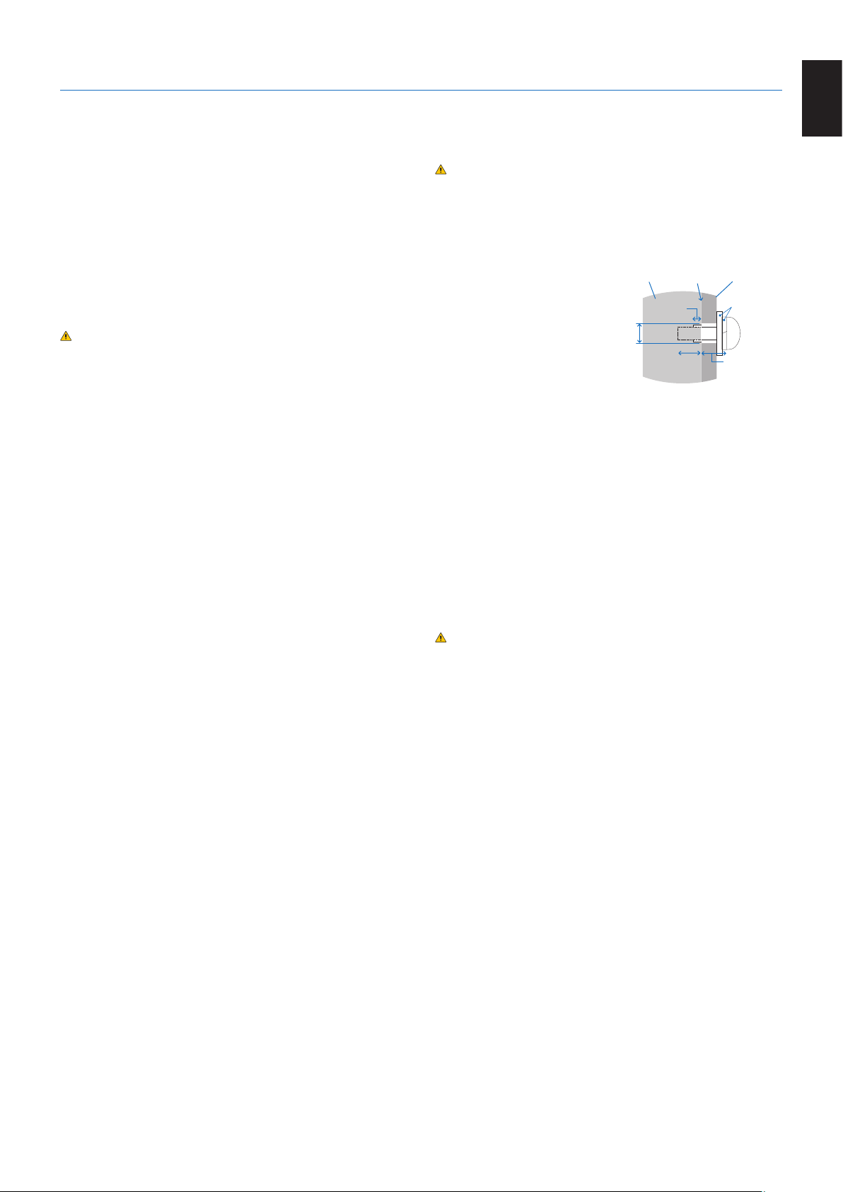
• NEC strongly recommends
using size M6 screws
(10-12 mm + thickness
of bracket and washers in
length). If using screws
longer than 10-12 mm,
check the depth of the
under
φ 8.5 mm
Unit
No thread
4 mm
No gap
10-12 mm
hole. (Recommended Fasten
Force: 470 - 635N•cm). Bracket
hole should be under φ 8.5 mm.
• Prior to mounting, inspect the installation location to
ensure that it is strong enough to support the weight of
the unit so that the unit will be safe from harm.
• For detailed information, refer to the instructions included
with the mounting equipment.
• Make sure that there is no gap between the monitor and
the bracket.
NOTE: When used in a video wall confi guration for a long
time, slight expansion of the monitors may happen
due to temperature changes. It is recommended
that over one millimeter gap is kept between
adjacent monitor edges.
CAUTION: • When installing, do not apply pressure to
the LCD panel or excessive force to any
part of the monitor by pushing or leaning
on it. This may cause the monitor to
become distorted or damaged.
• To prevent the monitor from falling off from
the wall or ceiling, NEC strongly
recommends using a safety wire.
• Please install monitor in a spot of the wall
or ceiling strong enough to support the
monitor.
• Prepare the monitor using mounting
accessories such as hook, eyebolt or
mounting parts and then secure the monitor
with a safety wire. The safety wire must
not be tight.
• Do not attempt to hang the monitor using
an installation safety wire. The monitor
must be properly installed on a VESA
compatible mount.
• Please make sure the mounting
accessories are strong enough to support
the monitor before mounting it.
Mounting
Bracket
Washers
Screw
Thickness
of bracket
and washers
English
English-5
Page 2
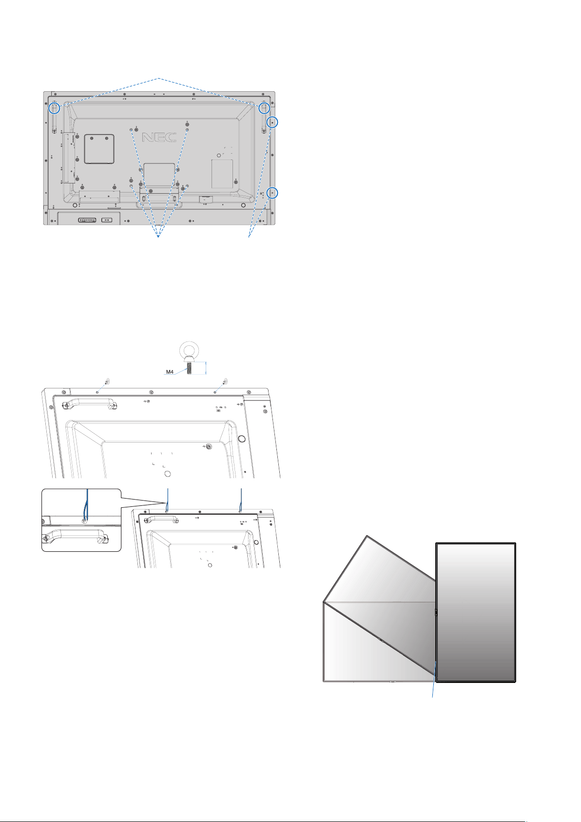
Please use the handles for landscape position and the two
mounting holes with using eyebolts for portrait position.
Safety wire for landscape position
VESA Mounting Interface (M6)
Installing a wire to a monitor for portrait position
Please use eyebolts to install a wire to the monitor.
To prevent the monitor from falling off from the wall or ceiling,
NEC strongly recommends using a wire.
Please install the monitor in a spot of the wall or ceiling
strong enough to support the monitor.
Safety wire for
portrait position
10-12 mm
Mounting location
• The ceiling and wall must be strong enough to support the
monitor and mounting accessories.
• DO NOT install in locations where a door or gate can hit
the unit.
• DO NOT install in areas where the unit will be subjected
to strong vibrations and dust.
• DO NOT install the monitor next to a location where the
main power supply is fed into the building.
• DO NOT install the monitor in a location where people
can easily grab and hang onto the unit or the mounting
equipment.
• Allow for adequate ventilation or provide air conditioning
around the monitor, so that heat can properly dissipate
away from the monitor and from the mounting equipment.
Mounting on ceilings
• Ensure that the ceiling is strong enough to support the
weight of the unit and the mounting equipment over time,
against earthquakes, unexpected vibrations, and other
external forces.
• Be sure the unit is mounted to a solid structure within
the ceiling, such as a support beam. Secure the monitor
using bolts, spring lock washers, washer and nut.
• DO NOT mount to areas that have no supporting internal
structure. DO NOT use wood screws or anchor screws for
mounting. DO NOT mount the unit to ceiling or to hanging
fi xtures.
Maintenance
• Periodically check for loose screws, gaps, distortions,
or other problems that may occur with the mounting
equipment. If a problem is detected, please refer to
qualifi ed personnel for service.
• Regularly check the mounting location for signs of
damage or weakness that may occur over time.
Orientation
• When using the monitor in the portrait position, it should
be rotated clockwise so that the left side is moved to
the top, right side is moved to the bottom. This will allow
for proper ventilation and will extend the lifetime of the
monitor. Improper ventilation may shorten the lifetime of
the monitor.
LED Indicator
English-6
Page 3

Changing NEC logo ornament position
When using the monitor in the portrait position, the NEC logo
ornament position can be changed.
Removing the logo ornament: unscrew the installed screw
then take off the logo ornament.
Attaching the logo ornament: adjust the protrusions inside
of the logo ornament into the protrusion holes on the bezel.
Make sure the hole for the screw on the logo ornament and
the hole for the screw on the bezel are aligned. Install the
logo ornament with the screw, which is used for installing the
logo ornament.
(Recommended Fasten Force: 30-40N•cm).
Screw hole
Protrusion hole
Protrusion
Inside of NEC logo ornament
Protrusion hole
Screw hole
Protrusion
When using mounting accessories other than NEC compliant
and approved, they must comply with the VESA Flat Display
Mounting Interface Standard (FDMI).
NOTE: Prior to installation, place the monitor face down
on a fl at even surface that is larger than the
monitor screen.
Use a sturdy table that can easily support the
weight of the monitor.
2. Installing an Option Board
1. Turn off the main power switch.
2. Place the monitor face down on the protective sheet.
NOTE: Be sure to place the monitor on a fl at and adequate
space.
3. Remove the attached slot cover by unscrewing the
installed screws (Figure 1), sliding to right (Figure 2) and
moving up (Figure 3).
English
CAUTION: Do not use any other screw to install the logo
ornament.
Attaching Mounting Accessories
The monitor is designed for use with the VESA mounting
system.
1. Attach Mounting Accessories
Be careful to avoid tipping the monitor when attaching
accessories.
VESA Mounting Interface (M6)
300 mm
300 mm
Mounting accessories can be attached with the monitor in
the face down position. To avoid scratching the LCD panel,
always place a soft cloth, such as a blanket that is larger
than the monitor’s screen area, on the table before laying the
monitor face down. Make sure there is nothing on the table
that can damage the monitor.
Figure 1 Figure 2
Figure 3 Figure 4
4. Insert the Option Board into the monitor and fi x it with the
removed screws (Figure 4).
NOTE: Please contact your supplier for a list of Option
Boards available for your monitor.
Do not apply excessive force to manipulate the
Option Board before fi xing it with screws.
Make sure that the board is inserted into the slot in
the correct orientation.
WARNING: Ensure the Option Board is attached by the
removed screws. Otherwise, the Option
Board may fall out and expose you to danger.
(Recommended Fasten Force: 139 - 189N•cm).
English-7
Page 4

3. Installing and Removing the Optional
Table Top Stand
CAUTION: • Installing and removing the stand must be
done by two or more people.
• ONLY use screws which are supplied with
the optional table top stand.
• When installing the monitor stand, handle
the unit with care to avoid pinching your
fi ngers.
For installation, follow the instructions included with the
stand or mounting equipment. Use only those devices
recommended by the manufacturer.
NOTE: • Use the ST-401. Please refer to the ST-401
user’s manual for more detail.
• DO NOT use this monitor on the fl oor with the
table top stand. Please use this monitor on a
table or with a mounting accessory for support.
CAUTION: Please refer to the table top stand manual of
ST-401 for “structure of Prevent Tipping”.
300 mm
2. Please install the stand pole and the pipe with included
screws. Please screw the two screw holes at the pipe
(Figure 4).
Pipe
Stand pole
Figure 4
CAUTION: Installing the monitor at the wrong height can
cause tipping.
Please install your monitor at proper height.
4. Ventilation Requirements
When mounting in an enclosed space or recessed area,
leave adequate room between the monitor and the enclosure
to allow heat to disperse, as shown below.
100 mm
Height adjustment
1. The lines on the stand pole are indicators of the height
adjustment (Figure 3). Please adjust the pipe to the lines.
Pipe
V554Q High/Low
Adjust the pipe to a line.
Figure 3
100 mm
100 mm
100 mm
Must be under 40 Degree Celsius.
30 mm
Allow adequate ventilation or provide air conditioning around
the monitor, so that heat can properly dissipate away from
the unit and the mounting equipment; especially when you
use monitors in a multiple screen confi guration.
NOTE: The sound quality of the internal speakers will be
different depending on the acoustics of the room.
English-8
Page 5

Setup
1. Determine the installation location
CAUTION
• Installing your monitor must be done by a qualifi ed
technician. Contact your supplier for more information.
• MOVING OR INSTALLING THE MONITOR MUST BE
DONE BY TWO OR MORE PEOPLE. Failure to follow
this caution may result in injury if the monitor falls.
• Do not mount or operate the monitor upside down.
NOTE: This monitor has internal temperature sensors and
cooling fans, including a fan for the Option Board.
If the monitor becomes too hot, the cooling fans
will turn on automatically.
The Option Board’s fan is active although the
temperature is lower than normal operating
temperature for cooling the Option Board. If the
monitor becomes overheated while the cooling
fan is running, a “Caution” warning appears. If the
“Caution” warning appears, stop using the unit,
turn off the power and allow it to cool. Using the
cooling fans will reduce the likelihood of early unit
failure and may help reduce image degradation
and “Image Persistance”.
CAUTION: If the monitor is used in an enclosed
area or if the LCD panel is covered with
a protective screen, please check the
inside temperature of the monitor by using
the [HEAT STATUS] control in the OSD
(see page 40). If the temperature is higher
than the normal operating temperature,
please turn the cooling fan to [ON] within
the [FAN CONTROL] menu within the OSD
(see page 40).
NEC recommends the following battery use:
• Place “AAA” size batteries matching the (+) and (-) signs
on each battery to the (+) and (-) signs of the battery
compartment.
• Do not mix battery brands.
• Do not combine new and old batteries. This can shorten
battery life or cause liquid leakage of batteries.
• Remove dead batteries immediately to prevent battery
acid from leaking into the battery compartment.
• Do not touch exposed battery acid, it may injure your skin.
NOTE: If you do not intend to use the Remote Control for
a long period of time, remove the batteries.
3. Connect external equipment
(See page 16, page 17 and page 18)
• To protect the external equipment, turn off the main power
before making connections.
• Refer to the user’s manual of your equipment for further
information.
NOTE: Do not connect/disconnect cables when turning
on the monitor or other external equipment as this
may result in a loss of the monitor image.
4. Connect the supplied power cord
The monitor should be installed close to an easily accessible
power outlet.
CAUTION: Fasten the power cord to the monitor
by attaching the screw and clamp.
(Recommended Fasten Force:
139 - 189N•cm).
IMPORTANT: To avoid scratching the LCD panel, always
place a soft cloth, such as a blanket that is
larger than the monitor’s screen area, on the
table before laying the monitor face down.
2. Install the remote control batteries
The remote control is powered by two 1.5V AAA batteries.
To install or replace batteries:
1. Press and slide to open the cover.
2. Align the batteries according to the (+) and (–) indications
inside the case.
3. Replace the cover.
CAUTION: Incorrect usage of batteries can result in
leaks or bursting.
WARNING: • Please refer to the “Important Information”
section of this user’s manual for proper
selection of an AC power cord.
• Fully insert the prongs into the power
outlet socket.
A loose connection may cause image
instability and may pose a fi re hazard.
Screw
Clamp
English-14
 Loading...