

Page 1

()
■■■■■■■
■■■■■■■
■■■■■■■
■■■■■■■
■■■■■■■
■■■■■■■
EXPRESS5800/320Lb/320Lb-R
User's Guide
■■■■■■■
■■■■■■■
■■■■■■■
■■■■■■■
■■■■■■■
■■■■■■■
■■■■■■■
■■■■■■■
Page 2

NEC
Page 3

Proprietary Notice and Liability Disclaimer
The information disclosed in this document, including all designs and related materials, is
the valuable property of NEC Solutions (America), Inc. and/or its licensors. NEC Solutions
(America), Inc. and/or its licensors, as appropriate, reserve all patent, copyright and other
proprietary rights to this document, including all design, manufacturing, reproduction, use,
and sales rights thereto, except to the extent said rights are expressly granted to others.
The NEC Solutions (America), Inc. product(s) discussed in this document are warranted in
accordance with the terms of the Warranty Statement accompanying each product.
However, actual performance of each product is dependent upon factors such as system
configuration, customer data, and operator control. Since implementation by customers of
each product may vary, the suitability of specific product configurations and applications
must be determined by the customer and is not warranted by NEC Solutions (America), Inc.
To allow for design and specification improvements, the information in this document is
subject to change at any time, without notice. Reproduction of this document or portions
thereof without prior written approval of NEC Solutions (America), Inc. is prohibited.
Trademarks
Windows 2000 is a registered trademark of Microsoft Corporation.
Intel is a registered trademark of Intel Corporation.
Xeon is a trademark of Intel Corporation.
All other product, brand, or trade names used in this publication are the trademarks or registered
trademarks of their respective trademark owners.
PN: 456-01675-000 February 2003
Copyright 2003
NEC Solutions (America), Inc
10850 Gold Center Drive, Suite 200,
Rancho Cordova, CA 95670
All Rights Reserved
Page 4

Page 5

Contents
Proprietary Notice
Using This Guide
Text Conventions...............................................................................................................viii
Related Documents .............................................................................................................. ix
Safety Notices....................................................................................................................... x
Safety Notices for Users Outside of the U.S.A. and Canada.......................................... xi
Care and Handling...............................................................................................................xii
1 System Overview
Overview............................................................................................................................ 1-2
Fault-Tolerant Hardware....................................................................................................1-4
System Chassis................................................................................................................... 1-5
Front View (Bezel Installed).........................................................................................1-5
Front View (Bezel removed).........................................................................................1-7
Rear View ..................................................................................................................... 1-9
CPU Module ............................................................................................................... 1-11
CPU Module Board.....................................................................................................1-12
PCI Module.................................................................................................................1-13
PCI Module Board...................................................................................................... 1-14
Chassis Board Layout (Rack-mount Model)...............................................................1-15
PCI Module LEDs............................................................................................................ 1-16
POWER LED..............................................................................................................1-16
BMC Status LED........................................................................................................1-16
PCI Module Status LEDs (1 and 2) and Disk Access LED........................................ 1-18
CPU Module LEDs..........................................................................................................1-19
CPU Module Status LEDs (1 and 2)........................................................................... 1-19
PCI Board Slot Status LEDs............................................................................................1-20
Hard Disk LED ................................................................................................................ 1-20
LAN Connector LEDs......................................................................................................1-21
System Components and Module Set...............................................................................1-22
CPU Modules..............................................................................................................1-22
PCI modules................................................................................................................ 1-22
Storage Bays ...............................................................................................................1-23
PCI Adapter Cards...................................................................................................... 1-24
Floppy Disk Drive.......................................................................................................1-25
Optional Components.......................................................................................................1-26
Monitor, Keyboard, and Mouse..........................................................................1-26
System Features ............................................................................................................... 1-26
Xeon Processor ...........................................................................................................1-26
System Memory..........................................................................................................1-26
SAF-TE Controller......................................................................................................1-26
BIOS ........................................................................................................................... 1-27
USB/IDE Controller....................................................................................................1-27
Network Controllers....................................................................................................1-27
SCSI Controller...........................................................................................................1-28
Video Controller .........................................................................................................1-28
Peripheral Controller...................................................................................................1-28
Contents iii
Page 6

Serial Ports...........................................................................................................1-28
Real Time Clock..................................................................................................1-28
Baseboard Management Controllers (BMC)...............................................................1-29
External Device Connectors........................................................................................1-29
2 Setting Up the System
Overview ............................................................................................................................2-2
Selecting a Site...................................................................................................................2-2
Unpacking the System........................................................................................................2-3
Installation..........................................................................................................................2-4
Tower Model.................................................................................................................2-4
Installation of Rack-mount Model.................................................................................2-7
Connections........................................................................................................................2-9
Connecting the Power Cord(s) .........................................................................................2-11
Basic Operation................................................................................................................2-12
Locking and Unlocking the Front Bezel .....................................................................2-12
Tower Model...............................................................................................................2-12
Rack-mount Model......................................................................................................2-13
Detach..................................................................................................................2-13
Attach ..................................................................................................................2-13
Power ON.........................................................................................................................2-14
Power OFF........................................................................................................................2-15
POST Check.....................................................................................................................2-15
Flow of POST..............................................................................................................2-16
Behavior at Occurrence of Error.................................................................................2-17
POST Error Messages.................................................................................................2-17
Forced Shutdown and Clear .............................................................................................2-18
Forced Shutdown.........................................................................................................2-18
3 Configuring Your System
Configuring Your System...................................................................................................3-2
BIOS Setup Utility..............................................................................................................3-3
Using the BIOS Setup Utility........................................................................................3-3
BIOS Setup Configuration Settings...............................................................................3-4
Main Menu....................................................................................................................3-5
Advanced Menu ............................................................................................................3-6
Advanced Submenu...............................................................................................3-7
Processor Information Submenu ...........................................................................3-7
Memory Information Submenu.............................................................................3-8
Peripheral Configuration Submenu.......................................................................3-8
Monitoring Configuration Submenu......................................................................3-9
Option ROM Submenu..........................................................................................3-9
Keyboard Features Submenu...............................................................................3-10
Security Menu.............................................................................................................3-11
System Hardware Menu..............................................................................................3-12
Thermal Sensor Submenu....................................................................................3-13
Wake On Events Submenu..................................................................................3-13
Console Redirection Submenu............................................................................3-13
Boot Menu...................................................................................................................3-14
Exit Menu....................................................................................................................3-14
Fast!Util Utility.................................................................................................................3-15
Running the Fast!Util..................................................................................................3-15
iv Contents
Page 7

Configuration Settings Menu......................................................................................3-16
Host Adapter Settings Submenu ......................................................................... 3-16
SCSI Device Settings Submenu..........................................................................3-17
SCSI Bus Settings Submenu............................................................................... 3-18
Autoconfigure SCSI Device Submenu................................................................3-18
Selectable Boot Settings Submenu......................................................................3-19
Restore Default Settings Submenu......................................................................3-19
Raw NVRAM Data Submenu.............................................................................3-19
Scan SCSI Bus............................................................................................................3-19
SCSI Disk Utility........................................................................................................ 3-20
Select Host Adapter ....................................................................................................3-20
Exit..............................................................................................................................3-20
Configuring System Jumpers...........................................................................................3-22
Before You Begin.......................................................................................................3-22
Moving System Jumpers............................................................................................. 3-24
Clearing CMOS and Password ...................................................................................3-25
4 CRU Replacement and Upgrades
General Information...........................................................................................................4-2
Precautions......................................................................................................................... 4-3
Preparing Your System for Upgrade..................................................................................4-5
Opening and Closing the Front Bezel ................................................................................4-6
Tower Model.................................................................................................................4-6
Rack-mount Model .......................................................................................................4-7
Detach ................................................................................................................... 4-7
Attach.................................................................................................................... 4-7
Replacing CPU Modules.................................................................................................... 4-8
Removing a CPU Module.............................................................................................4-8
Installing a CPU Module...............................................................................................4-9
Replacing or Adding Processors...................................................................................... 4-11
Installing a Processor.................................................................................................. 4-11
Removing a Processor.................................................................................................4-16
Replacing or Adding DIMMs..........................................................................................4-19
Installing DIMMs........................................................................................................4-20
Removing DIMMs...................................................................................................... 4-21
Replacing a PCI Module.................................................................................................. 4-22
Removing a PCI Module.............................................................................................4-22
Installing a PCI Module..............................................................................................4-24
Installing PCI Adapter Boards.........................................................................................4-25
Installing a Hard Disk Drive ............................................................................................ 4-29
Removing a Hard Disk Drive......................................................................................4-31
Hot-Swapping a Hard Drive .......................................................................................4-32
5 Problem Solving
Problem Solving.................................................................................................................5-2
Static Precautions...............................................................................................................5-2
Troubleshooting Checklists................................................................................................5-3
Initial System Startup....................................................................................................5-3
Checklist .......................................................................................................................5-3
Running New Application Software.............................................................................5-4
Checklist .......................................................................................................................5-4
After System Has Been Running Correctly..................................................................5-5
Contents v
Page 8

Checklist........................................................................................................................5-5
Diagnostic Procedures........................................................................................................5-6
Error Checking..............................................................................................................5-6
Troubleshooting Guide..................................................................................................5-6
Preparing the System for Diagnosing Problems....................................................5-6
Monitoring POST..................................................................................................5-7
Verifying Proper Operation of Key System Indicators.........................................5-8
Confirming Loading of the Operating System......................................................5-8
Specific Problems and Corrective Actions.........................................................................5-9
Power LED Does Not Light..........................................................................................5-9
Incorrect or No Beep Code............................................................................................5-9
No Characters Appear on Screen................................................................................5-10
Characters are Distorted or Incorrect ..........................................................................5-10
Diskette Drive Activity LED Does Not Light.............................................................5-11
CD-ROM Drive Activity Light Does Not Light .........................................................5-12
Problems with Application Software...........................................................................5-12
Bootable CD-ROM Is Not Detected............................................................................5-12
Problems with the Network..............................................................................................5-13
PCI Installation Tips.........................................................................................................5-13
Error Messages and Beep Codes......................................................................................5-14
MWA/ESMPRO Error Messages................................................................................5-14
POST Error Codes and Messages................................................................................5-26
How to Identify BIOS and BMC Revision Levels...........................................................5-34
BIOS Revision Level Identification............................................................................5-34
BMC Revision Level Identification ............................................................................5-34
A Technical Specifications
Server Unit.........................................................................................................................A-2
B I/O Port Addresses
I/O Port Address................................................................................................................B-2
Glossary
Equipment Log
INDEX
vi Contents
Page 9

Using This Guide
This User’s Guide provides a quick reference to information about your fault-tolerant
server system. Its goal is to familiarize you with your system and the tasks necessary for
system configuring and upgrading.
This guide contains the following information:
! Chapter 1, “System Overview” provides an overview of your system and describes your
system’s major system components. See this chapter to familiarize yourself with your
system.
! Chapter 2, “Setting Up Your System” tells you how to select a site, unpack the system,
assemble the rack-mount system, make cable connections, and how to use your system.
! Chapter 3, “Configuring Your System” tells you how to configure the system and
provides instructions for running the BIOS Setup Utility and the Fast!Util Configuration
Utility, which is used to configure SCSI devices in your system. This chapter also
provides information on system board jumper settings.
! Chapter 4, “CRU Replacement and Server Upgrades” provides you with instructions on
how you can access, remove, and install Customer-Replaceable Units (CRUs) and
directions for upgrading your server system with additional processors, optional
memory, and options cards.
! Chapter 5, “Problem Solving” contains helpful information for solving problems that
might occur with your system.
! Appendix A, “Specifications” provides specifications for your server unit.
! Appendix B, “I/O Port Addresses” defines the factory-set I/O port addresses for the
server.
! “Glossary” defines the standard acronyms and technical terms used in this manual.
Using This Guide vii
Page 10
Text Conventions
This guide uses the following text conventions.
Warnings, cautions, and notes have the following meanings:
Warnings alert you to situations that could result in serious personal injury or loss
of life.
Cautions indicate situations that can damage the system hardware or software.
Note: Notes give important information about the material being described.
! Names of keyboard keys are printed as they appear on the keyboard. For example, Ctrl,
Alt, or Enter.
!
WARNING
!
CAUTION
! Text or keystrokes that you enter appear as boldface type. For example, type abc123 and
press ENTER.
! File names are printed in uppercase letters. For example, AUTOEXEC.BAT.
viii Using This Guide
Page 11

Related Documents
In addition to this guide, the following system documentation is included with your server
either as electronic files on EXPRESSBUILDER or as paper copy shipped with your server.
! System Release Notes
Release Notes provide you with the latest information about your system. This
information was not available to be included in your user's guide at the time it was
developed and released.
! Getting Started Sheet
The Getting Started Sheet provides several easy-to-follow steps to become familiar with
your server documentation and to complete your installation successfully.
! EXPRESSBUILDER User's Guide
The EXPRESSBUILDER User's Guide contains the instructions needed for reloading
the operating system (OS) and installing ESMPRO and MWA support programs.
! ServerCare
The ServerCare Guide contains information about NEC's warranty and server
registration.
SM
Guide
Using This Guide ix
Page 12

Safety Notices
General Notices
Lithium batteries can be dangerous. Improper handling of lithium batteries may
result in an explosion. Dispose of lithium batteries as required by local ordinance.
Replace only with the same or equivalent type battery.
The CD-ROM drive uses a laser beam. Do not look or insert a mirror inside while
the system is on. A laser beam is invisible; if your eyes get exposed to it, there is
a risk of losing your eyesight.
This equipment uses 3-wire, grounded power cords. To prevent electrical
hazards, do not remove or defeat the ground prong on the power cords. Replace
a power cord if it gets damaged. The detachable power supply cords are intended
to serve as the disconnect devices. Contact your dealer for an exact replacement.
The DC push-button on/off switch does not turn off the system AC power. Also,
+5vdc is present within the system whenever the AC power cords are connected
between the system and an AC outlet. Before doing the procedures in this
manual, make sure that your system is powered off and unplug the AC power
cords from the back of the chassis. Failure to disconnect power before opening
your system can result in personal injury and/or equipment damage.
!
WARNING
Under no circumstances should you attempt to disassemble a power supply. The
power supply has no user-replaceable parts. Inside the power supply are
hazardous voltages that can cause serious personal injury. A defective power
supply must be returned to your dealer.
Never connect the ground wire to a gas pipe. There is a risk of a gas explosion.
The equipment weighs around 60 to 70 kg (depending on its hardware
configuration). If you carry it alone, injuries may result. It takes at least four
people to carry it; hold the equipment firmly by its bottom. Do not hold the front
bezel, or it may become detached, causing an injury.
Immediately after powering off the system, components such as CPU processor
heat sinks and hard disk drives may be very hot. Wait for the server to cool down
completely before adding/removing components.
Do not attempt to remove a device while it is in operation. Device malfunction or
personal injury may result.
Be careful not to get your fingers or hair caught in cooling fans located in the back
of a running server.
! Be sure to power off the equipment and unplug its power cords from the wall outlet
before installation/relocation. All voltage is removed only when the power cords are
unplugged.
! Turn off your cellular phone or pager when you use the equipment. Their radio waves
may cause the equipment to malfunction.
x Using This Guide
Page 13

! Do not use damaged power cords. (Replace it with a new one of the same type.)
! In the U.S.A. and Canada, the power cord must be a UL-listed detachable power cord (in
Canada, CSA-certified), type ST or SJT, 16 AWG, 3-conductor, provided with a
molded-on NEMA type 5-15 P plug cap at one end and a molded-on cord connector
body at the other end. The cord length must not exceed 9 feet (2.7 meters).
! Outside the U.S.A. and Canada, the plug must be rated for 250 VAC, 10 amp minimum,
and must display an international agency approval marking. The cord must be suitable
for use in the end-user country. Consult your dealer or the local electrical authorities if
you are unsure of the type of power cord to use in your country. The voltage change
occurs via a switch in the power supply.
Safety Notices for Users Outside of the U.S.A. and Canada
! PELV (Protected Extra-Low Voltage) Integrity: To ensure the extra-low voltage
integrity of the equipment, connect only equipment with mains-protected electricallycompatible circuits to the external ports.
! Remote Earths: To prevent electrical shock, connect all local (individual office)
computers and computer support equipment to the same electrical circuit of the building
wiring. If you are unsure, check the building wiring to avoid remote earth conditions.
! Earth Bonding: For safe operation, only connect the equipment to a building supply
that is in accordance with current wiring regulations in your country. In the U.K., those
regulations are the IEE.
Using This Guide xi
Page 14

Fire Related Notices
To prevent fires, and damage to the equipment and supply wiring, make sure that
the rated load of the power branch circuit is not exceeded. Equipment nameplate
ratings should be used when addressing this concern. For more information on
installation and wiring of power-related facilities, contact your ele ctrician or local
power company.
If the equipment emits smoke, odor, or noise, immediately turn off the POWER
switch, unplug the cord, and contact your sales agent. There may be a risk of a
fire.
Use a wall outlet with the specified voltage rating and power type. Otherwise,
there is a risk of a fire or current leakage.
Avoid installing the equipment where you may need to use an extension cord. If
you use a cord that does not meet power specifications, there is a risk of
overheating that could lead to a fire.
Insert the plug firmly into an outlet. Otherwise, there is a risk of heat or fire due to
poor contact. If dust settles on the slots and it absorbs moisture, there is also a
risk of heat or fire.
!
CAUTION
Use only the supplied power cords. If the rated current of the power cord is
exceeded, there is a risk of a fire. Also observe the following prohibitions to
prevent damage to cords:
Do not pull on the cord.
Do not pinch the cord.
Do not bend the cord.
Keep chemicals away from the cord.
Do not twist the cord.
Do not place any object on the cord.
Do not bundle several cords.
Do not alter, modify, or repair the cord.
Do not staple the cord.
Use only interface cables designed for your server. Identify which component or
connector to attach beforehand. If you use a wrong cable or make a wrong
connection, there is a risk of short-circuit that could lead to a fire. You also have
to observe the following prohibitions about handling and connecting interface
cables:
Do not use any damaged cable connector.
Do not step on the cables.
Disconnect the power plug from the outlet occasionally and clean the plug with a
dry cloth. Heat will be generated if condensation is formed on a dusty plug, which
may cause a fire.
Firmly install all power cords, interface cables and/or boards. An incompletely
installed component may cause a contact failure, resulting in fire and/or smoke.
xii Using This Guide
Page 15

Shock Related Notices
Do not insert a wire or metal objects into a vent or disk drive slot. There is a risk
of an electric shock.
Do not let water or foreign objects (e.g., pins or paper clips) enter the equipment.
There is a risk of a fire, electric shock, and breakdown. When such objects
accidentally enter the equipment, immediately turn off the power and unplug the
cord. Contact your sales agent instead of trying to disassemble it yourself.
Do not plug/unplug a power cord with a wet hand. There is a risk of an electric
shock.
Make sure to power off the server and unplug the power cord from a power outlet
before installing/removing any optional internal device or
connecting/disconnecting any interface cable to/from the server. If the server is
powered off, but its power cord is plugged to a power source, touching an internal
device, cable, or connector may cause an electric shock or a fire.
Unless described herein, never attempt to disassemble, repair, or alter the
equipment. There is a risk of an electric shock or fire as well as malfunction.
You may want to unplug the equipment if a thunderstorm is eminent. Do NOT
touch the equipment and cables during a thunderstorm in your area. There is a
risk of a fire or electric shock.
!
WARNING
Make sure to power off the server and disconnect the power plug from a power
outlet before cleaning or installing/removing internal optional devices. Touching
any internal device of the server with its power cord connected to a power source
may cause an electric shock even of the server is off-powered.
Using This Guide xiii
Page 16

Rack-mount Related Notices
To avoid a risk of injuries, users should not attempt to install the equipment into a
rack. Installation should be performed by trained maintenance personnel.
It takes at least two people to carry or maneuver a rack. Otherwise, it may be
dropped and cause injuries or damage to physical assets. A tall rack (such as
44U rack) is quite unstable, especially when not fixed by stabilizers.
For stability and to distribute the weight, attach stabilizers or install two or more
racks together. Otherwise, the rack may topple over and cause injuries.
It takes at least two people to mount doors and trays to a rack. Otherwise, parts
may be dropped causing breakage or injuries.
If you extend two or more devices from the rack at the same time, the rack may
topple over on you. Extend only one device from the rack at a time.
Install the equipment into a 19-inch rack conforming to EIA standards. Do not use
the equipment without a rack or install it on a nonconforming rack. Otherwise, the
equipment may not function properly, and there is a risk of equipment damage or
personal injury. For suitable racks, contact your sales agent.
!
WARNING
Exercise great care not to hurt your fingers on the rail when you mount/dismount
the equipment into/from the rack.
! Elevated Operating Ambient Temperature – If installed in a closed or multi-unit rack
assembly, the operating ambient temperature of the rack environment may be greater
than the room ambient environment. Therefore, consideration should be given to
installing the equipment in an environment compatible with the a maximum rated
ambient temperature of 35°C. Refer to Chapter 2 on this manual for more details on
room ambient temperature.
! Reduced air Flow – Installation of the equipment in a rack should be such that the
amount of air flow required for safe operation of the equipment is not compromised.
! Before pulling a server or device out of a rack, make sure that the rack is secured by
stabilizers.
! To prevent fires, and damage to rack equipment and supply wiring, make sure that the
rated load of the power branch circuit is not exceeded. Equipment nameplate ratings
should be used when addressing this concern. For more information on installation and
wiring of power-related facilities, contact your electrician or local power company.
! To prevent electrical shock, connect all rack and rack support equipment to the same
electrical circuit of the building wiring. If you are unsure, check the building wiring to
avoid remote earth conditions.
! For safe operation, only connect the equipment to a building supply that is in accordance
with current wiring regulations in your country. In the U.K., those regulations are the
IEE.
xiv Using This Guide
Page 17

Care and Handling
Use the following guidelines to properly handle and care for your system.
Protect the system from extremely low or high temperatures. Let
the system warm (or cool) to room temperature before using it.
Keep the system away from magnetic forces.
Keep the system dry. Do not wash the system with a wet cloth or
pour fluid into it.
Protect the system from being bumped or dropped.
Check the system for condensation. If condensation exists, allow it
to evaporate before powering on the system.
Keep the system away from dust, sand, and dirt.
Using This Guide xv
Page 18

System Overview
! Overview
! Fault-Tolerant Hardware
! System Chassis
! PCI Module LEDs
! CPU Module LEDs
! PCI Board Slot Status LEDs
! Hard Disk LED
! LAN Connector LEDs
1
! System Components and Module Set
! Optional Components
! System Features
Page 19
Overview
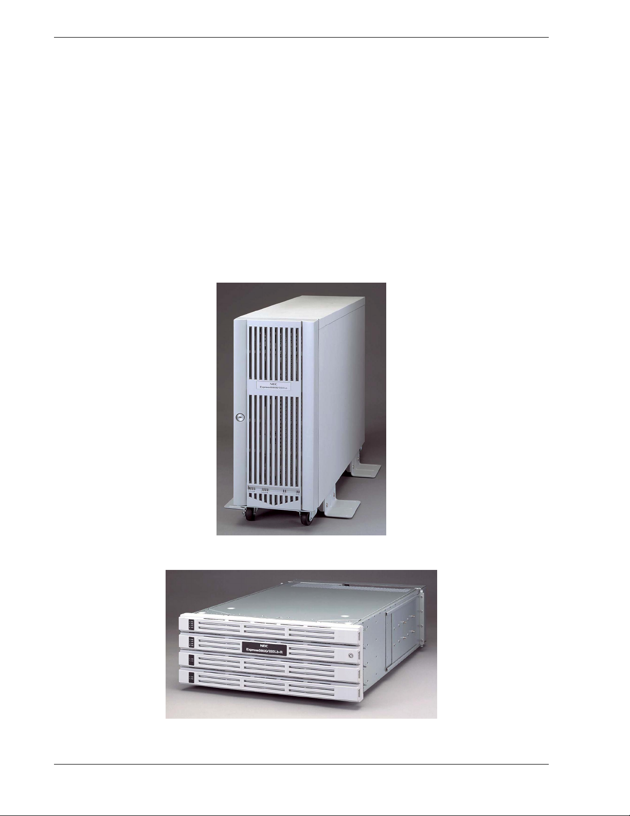
This server is well suited for Symmetric Multiprocessing (SMP) and Enterprise class
network server environments and is a highly reliable, high-powered, fault-tolerant,
high-capacity multiprocessing system based on the Intel Xeon® processor family. It is
a fully redundant system with on-line serviceability and hot plug replacement of all
major subsystems and a solid performer offering the latest technology. The server is
conveniently housed and available as a tower-based system (see Figure 1-1) or as a
rack-mount system (see Figure 1-2) in a relatively small form factor (fits into a standard
EIA 19-inch rack assembly.)
The combination of mirrored computing performance, memory capacity, and integrated
I/O provides a high performance environment for many applications including network
servers. The server is designed for use in applications where fault-tolerant, advanced
technology, high performance, and high levels of reliability and compatibility are
expected.
1-2 System Overview
Figure 1-1. Tower-Based System
Figure 1-2. Rack-Mount System
Page 20

This server is designed for full redundancy and hot plug replacement of all major
subsystems. The system modules that can be replaced are identified as Customer
Replaceable Units (CRUs) of which most are redundant and hot pluggable. To this end,
the server includes or has the option to include the following:
! SCSI hard disk drive bays accessible from the front of the chassis.
! Hot-swap SCSI disk drive backplane; a failed drive can be removed and replaced
with a new drive without system power being turned off.
! High degree of SCSI disk fault tolerance and advanced disk array management
features.
! Video Graphics Array (VGA) controller with 2 MB of video memory (occupies one
PCI slot per PCI module).
! SCSI disk adapter providing Ultra 160 SCSI interface for the hot swap hard disk
drives.
! Embedded single channel enhanced IDE adapter providing interface for a peripheral
device (CD-ROM drive).
! Integrated Network Interface Controller (NIC), supporting 10Base-T/100Base-
TX/1000Base-T network systems.
! Storage module that holds up to six hot-swap SCSI hard disk drives (three logical
disks).
! SCSI backpanel is Ultra2 capable.
! Integrated dual Universal Serial Bus (USB) ports that include support for the
keyboard, mouse, and a USB floppy diskette drive.
! Hardware monitors (temperature, fans, and voltage) and software monitors to
indicate failures.
! Easy access to all parts for service.
System Overview 1-3
Page 21

As application requirements increase, you can expand your server with additional
processors, additional memory, add-in boards and peripheral devices.
Your server features the following major components:
! Up to two high-performance Xeon 2.4GB processors in each CPU module.
! Up to 3 GB of Synchronous Dynamic Random-Access (SDRAM) system memory in
each CPU module.
! Three PCI expansion slots, which support one 32-bit/33Mhz and two 64-bit/33Mhz
PCI adapter cards in each PCI module. One of the PCI expansion slots in each PCI
module contains a graphics board.
Fault-Tolerant Hardware
The hardware architecture of the system provides fault tolerance transparency. If a
hardware component fails, the application program continues processing and is never
aware that a failure occurred.
To provide system redundancy this system uses dual hardware technology. That means
that all major components are mirrored within a single hardware chassis. There are two
CPU modules and each CPU module is operating in lockstep (performing the same
instructions at the same time) with the other as a single system. Thus, if a failure occurs
in one CPU module the other CPU module will continue to operate with no
interruption, no loss of data, and system performance is not affected. Note that the PCI
module, PCI adapters, and power supplies are also paired for system redundancy.
1-4 System Overview
Page 22

System Chassis
The system chassis is a fabricated metal structure. The following subsections describe
the system chassis external view, internal view, and the system board set.
Front View (Bezel Installed)
Figure 1-3 shows the front chassis features and controls visible with the front bezel
installed.
1
2
Tower Model
7
5
6
7
8
5
6
8
3
5678 910
43
B
2
1
B
2
1
2
1
Rack-mount Model
5678
910
1
2
9
10
9
10
2
1
System Overview 1-5
Page 23

1 Front bezel
A door that covers internal components. You can lock it with the included security key.
2 Key slot
Insert the security key in this slot to unlock the front bezel.
3 Stabilizers
Parts for stabilizing a tower-model unit.
4Casters
Wheels for moving a tower-model unit.
5 BMC status LED
See “LEDs” in this chapter for details.
6 PCI module status LED 1
See “LEDs” in this chapter for details.
7 PCI module status LED 2
See “LEDs” in this chapter for details.
8 DISK ACCESS LED
See “LEDs” in this chapter for details.
9 CPU module status LED 1
See “LEDs” in this chapter for details.
10 CPU module status LED 2
See “LEDs” in this chapter for details.
Figure 1-3. Front Chassis Features and Controls (Bezels installed)
1-6 System Overview
Page 24

Front View (Bezel rem o ved)
Figure 1-4 shows the front chassis features and controls visible with the front bezel
removed.
5
6
7
1234
9
8
8
Tower Model
96
Rack-mount Model
57
1
2
3
4
System Overview 1-7
Page 25

1 PCI module (for group 1)
A module that includes a PCI board and LAN controller.
2 PCI module (for group 2)
A module that includes a PCI board and LAN controller.
3 CPU module (for group 1)
A module that includes a CPU (processor) and memory (DIMM).
4 CPU module (for group 2)
A module that includes a CPU (processor) and memory (DIMM).
5 POWER switch
A switch for turning on/off power to the system. The POWER switch on the primary PCI
module will be lit. Press it once to turn on power. Press it again to turn off power. Depress
the switch for more than four seconds to force the system to power down. The POWER
switch on the secondary PCI module will be unlit and will not respond until a failure in the
primary PCI module causes the secondary PCI module to assume primary functionality.
6 CD-ROM drive
Used for reading data from CD-ROMs.
Although there are two CD-ROM drives, only the one on the active primary PCI module can
be used (the module with the lit POWER Switch LED).
7 3.5-inch disk bay
Slots for adding hard disks. On a tower model, they are called Slots 1, 2, and 3 from the
bottom. On a rack-mount model, they are called Slots 1, 2, and 3 from the left. Slots of the
same number are mirrored between the groups 1 and 2.
8 DUMP switch
A switch for outputting a memory image from the kernel to a file.
9
DISK LED (green/amber)
An LED that blinks in green while the hard disk is accessed. When operating in simplex
mode or the hard disk fails, it will turn amber.
Figure 1-4. Front Chassis Features and Controls (Bezels installed)
1-8 System Overview
Page 26

Rear View
Figure 1-5 shows the rear chassis features and controls visible.
8
9
10
11
12
13
14
15
16
7
1
18
17
8 9 10 11 12 1314 15
7
Rack-mount Model
4
56
Tower Model
23
16 17
18
1
2
3
4
6
5
System Overview 1-9
Page 27

1 Serial port A connector
Connected to a device that has a serial interface. For maintenance use only.
2 AC inlet
PC socket for plugging a power cord.
3 Serial port B connector
Connected to a device that has a serial interface. For maintenance use only.
4 USB connectors 1 and 2
Connected to devices that support the USB interface.
Connect the mouse/keyboard to USB 1; connect the floppy diskette drive to USB 2.
5 AC inlet
AC socket for plugging a power cord.
6 Monitor connector
Connected to the display unit.
7 SCSI connector
Used for connecting external SCSI devices.
8 PCI module status LED 1
See “LEDs” in this chapter for details.
9 PCI module status LED 2
See “LEDs” in this chapter for details.
10 PCI board slot status LED (Slot1)
See “LEDs” in this chapter for details.
11 PCI board slot status LED (Slot2)
See “LEDs” in this chapter for details.
12
13
14
15
16
17
18
PCI board slot status LED (Slot3)
See “LEDs” in this chapter for details.
LINK/ACT LED LAN connector 2
See “LEDs” in this chapter for details.
LAN connector 2
A connector for 1000BASE-TX, 100BASE-TX, and 10BASE-T. Connected to the
network system on LAN.
100/10 LED LAN connector 2
See “LEDs” in this chapter for details.
LINK/ACT LED LAN connector 1
See “LEDs” in this chapter for details.
100/10 LED LAN connector 1
See “LEDs” in this chapter for details.
LAN connector 1
A connector for 100BASE-TX and 10BASE-T. Connected to the network system on
LAN.
1-10 System Overview
Figure 1-5. Rear View
Page 28

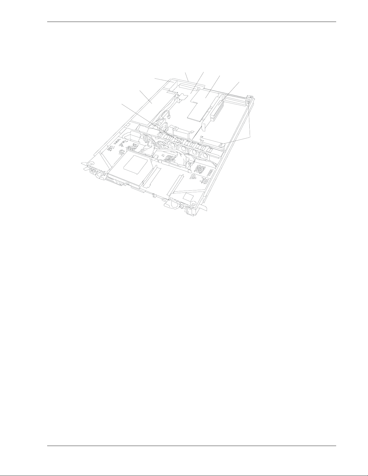
CPU Module
Figure 1-6 shows the internal components of the CPU Module. Both CPU modules in
the server are identical.
1
2
3
4
5
6
7
8
9
10
1
2
3
4
5
6
7
8
9
10
1
Module handle
Cooling fans
CPU module board
CPU socket #2 (additional)
AC inlet (in the back)
Backboard connector (in the back)
CPU socket #1 (standard)
DIMMs
Power unit
Power backboard
Figure 1-6. CPU Module
System Overview 1-11
Page 29

CPU Module Board
Figure 1-7 shows the major components of the CPU module board.
12
3
4
1
Group 1
2
3
Group 2
4
5
Group 3
6
56
CPU Module Board
3
1 Cooling fan connector
2 LED connector
3 Power connector
4CPU socket #2
5CPU socket #1
6 DIMM sockets (Slots #1 to #6 from top to bottom). Add memory modules in pairs: #1 and
#2, #3 and #4, #5 and #6.)
*This section only describes connectors that are used for replacing parts or upgrading. Other connectors have been setup
before shipment.
Figure 1-7. CPU Module Board
1-12 System Overview
Page 30
PCI Module
Figure 1-8 shows the internal components of the PCI module. Both PCI modules in the
server are identical.
1 Cooling fans
2 Power unit
4
3
5
6
7
2
1
8
3 AC inlet (in the rear)
4 Backboard connector (in the rear)
5 PCI module board
6 Video board
7 PCI riser card
8 PCI board retention bracket
Figure 1-8 PCI Module
System Overview 1-13
Page 31

PCI Module Board
Figure 1-9 shows the major components of the PCI module board.
1
23
1 SCSI connector (external)
2 Configuration jumper pin
3 Battery (lithium battery)
4 Cooling fan 1 connector
5 Power connector
6 IDE connector
7 Power switch connector
8
4
56789
8
9
LED connector
SCSI connector (internal)
1-14 System Overview
Figure 1-9. PCI Module Board
Page 32

Chassis Board Layout (Rack-mount Model)
Figure 1-10 shows the location of the clock board, I/O interface board and the back
panel in the rack-mount model. In the tower model, these components are located at the
lower rear of the plug-in modules.
Clock board
Interface board
Back panel
Figure 1-10. Chassis Board Layout
System Overview 1-15
Page 33

PCI Module LEDs
This section describes the LED indicators located in the PCI Module and will assist you
in determining the appropriate action to take as the result of a specific LED indications.
PCI Module LEDs include the Power LED, the BMC LED, the PCI Status LEDs 1 and
2 and the Disk Access LED.
POWER LED
The POWER switch of the primary PCI module also functions as a POWER LED. See
Figure 1-4. When AC power is supplied to the modules, the POWER LED on the
primary PCI module illuminates. The POWER switch on the secondary PCI module
will be unlit and will not respond until a failure in the primary PCI module causes the
secondary PCI module to assume primary functionality.
BMC Status LED
The BMC Status LED located on the front of the PCI module (see Figure 1-3)
indicates the status of the Baseboard Management Controller (BMC).
The LED stays green while the server is running normally. If the LED is not green,
there is something wrong with the server.
The Table 1-1 shows the indications of the BMC Status LED and their meanings.
Tips:
! To determine the cause of trouble, use ESMPRO or the Off-line Maintenance Utility to
view the error log.
! When you want to restart the server, perform a shutdown if the OS allows you to shut
down the system. If not, perform a reset or forced shutdown, or you can restart the
server by unplug and plugging the power cord.
Table 1-1. BMC Status LED
LED indications Description Action
Green BMC operates
normally and CPU
and PCI modules
are in duplex
mode.
Green (blinking
every 1 second)
Off
Amber Detected a fatal
CPU or PCI
modules are not in
duplex mode
during operation.
AC power is all off. Turn on the AC power.
Performing POST. Wait for a while; it will illuminate in green shortly after
CPU module error
occurred.
PCI module error
occurred.
temperature error.
Remount components whose Status LED is red. If the
problem persists, replace that module.
POST.
After turning off the power, turn it on to restart the
system. If some error message appears on the POST
screen, write it down and contact your sales agent.
If LCD displays some error message, refer to the error
message list (see Chapter 5).
Check if dust is accumulated on internal fans and
confirm that the fan cables are connected firmly. If the
message does not disappear, contact your sales
agent.
1-16 System Overview
Page 34

LED indications Description Action
Amber (blinking
every 1 second)
Red in one module
Red in both
modules
Red (blinking every
1 second)
Red (blinking every
0.5 second)
Detected a fatal
voltage error .
Detected a
temperature error
to be warned.
Detected a voltage
error to be warned.
Detected a device
defect.
Detected a fan
alarm.
BMC is being
dumped
PCI module may
be connected
incorrectly.
BMC may be out of
order.
Both BMCs are out
of order.
Revisions to BMC
firmware don’t
match.
Transfer of synced
data after a PCI
module is replaced
(this is not an
error).
Contact your sales agent.
If LCD displays some error message, refer to the error
message list (see Chapter 5).
Check if dust is accumulated on internal fans and
confirm that the fan cables are connected firmly. If the
message does not disappear, contact your sales
agent.
Contact your sales agent.
If LCD displays some error message, refer to the error
message list (see Chapter 5).
Check if dust is accumulated on internal fans, and
confirm that the fan cables are connected firmly. If the
message does not disappear, contact your sales
agent.
Wait for a while; it will go off soon.
Check if PCI module is connected correctly. Look for
loose screws.
BMC firmware may need reprogramming. Contact
your sales agent.
Check if both PCI modules are connected correctly.
Look for loose screws. If the message does not
disappear, contact your sales agent.
Contact your sales agent.
Do not loosen a screw on PCI modules or turn off the
AC power before the LED stops blinking.
System Overview 1-17
Page 35

PCI Module Status LEDs (1 and 2) and Disk Access LED
The PCI module has three LEDs that combined, indicate the status of the PCI modules
and hard disks. These LEDs are located on the front of each PCI module in the server
and are described in Table 1-2. Refer to Figure 1-3 for the location of these three LEDs
on the front of the PCI Module. The two PCI Module status LEDs are also visible from
the rear of the server. Refer to Figure 1-5 for the location for these LEDs on the rear of
the server.
Table 1-2. PCI Module Status and Disk Access LEDs
LED indications
12
Green
Off
Off Off AC power is not supplied to the PCI
Amber Amber
Green Off The PCI module is performing diagnosis. –
Red
Off Off
Amber
Disk
Access
Green
Off Disk Access LED is off only on one PCI
Green
Amber
Description Action
Status LEDs and Disk Access LED stay
green on both PCI modules, they operate
normally in duplex mode.
Status LEDs and Disk Access LED stay
green only on one module, there is some
kind if trouble with the hard disk.
In this case, Status LED 2 and Disk
access LED on the other PCI module
stay in amber.
module; power is not supplied to the hard
disk.
In this case, Status LED 2 and Disk
access LED on the other PCI module
stay in amber.
modules.
Status LEDs and Disk Access LED stay
amber on both PCI modules, they are
shifting to duplex mode by mirroring.
The PCI module is mounted correctly
and operates in simplex mode.
On standby (AC power is supplied
through the cord, but the system has not
been powered on yet.)
Power is not supplied due to a failure of
the CPU module.
Memory is being dumped.
Check the condition of hard disk
mirrors.
If the problem persists, contact your
sales agent.
Check the condition of hard disk
mirrors.
Remount the hard disks.
If the problem persists, contact your
sales agent.
Remount the PCI module.
Check the condition of power unit.
Check if the power cord is connected
correctly.
Check the condition of breaker and
UPS.
If the problem persists, contact your
sales agent.
Wait until the mirroring is finished.
Start the other PCI module to use ft
series features. If the problem
persists, contact your sales agent.
After turning on the power, wait for the
OS to start. When the OS starts and
duplex mode is established, the
indications will get back to normal. If
they do not get back to normal,
remount the CPU module.
Remount the CPU module. If the
problem persists, contact your sales
agent.
–
1-18 System Overview
Page 36

CPU Module LEDs
This section describes the LED indicators assist you in determining the appropriate
action to take as the result of a specific LED indications. PCI Module LEDs include the
CPU Status LEDs 1 and 2.
CPU Module Status LEDs (1 and 2)
The two CPU module LEDs combined show the status of CPU modules. These LEDs
are located on the front of each CPU module on the server and are described in
Table 1-3. Refer to Figure 1-3 for the location of these LEDs on the front of the CPU
Module.
Table 1-3 CPU Status LEDs
LED status
12
Off
Red
Green The CPU module
Off Power is not supplied to
Amber The CPU module is
Green The CPU module is
Off
Amber Memory is being
Description Action
operates normally in
duplex mode.
Remount the CPU module.
the CPU module.
mounted correctly and
operates in simplex
mode.
performing diagnosis.
On standby (AC power is
supplied through the
cord, but the system has
not been powered on
yet.)
Power is not supplied due
to a failure of the CPU
module.
dumped.
Check the condition of power unit.
Check if the power cord is connected
correctly.
Check the condition of breaker and UPS.
If the problem persists, contact your sales
agent.
Start the other CPU module to use ft
series features. If the problem persists,
contact your sales agent.
After turning on the power, wait for the
OS to start. When the OS starts and
duplex mode is established, the
indications will get back to normal. If they
do not get back to normal, remount the
CPU module.
Remount the CPU module. If the problem
persists, contact your sales agent.
–
–
–
System Overview 1-19
Page 37

PCI Board Slot Status LEDs
Up to three PCI boards may be installed in each PCI Module. One of these slots is
dedicated to the VGA graphics board. Refer to Figure 1-5 for the location on the PCI
board slot status LEDs. To show the status of PCI board slots, each PCI module has
three status LEDs. The PCI Board Slot status LEDs are described in the following table.
Table 1-4. PCI Board Slot Status LEDs
LED
indications
Off
Amber Performing POST; or
Red Although the PCI
Description Action
PCI board is mounted
correctly and operates
in duplex mode.
The PCI board is not
mounted; is mounted
incorrectly; or power
is not supplied.
the PCI board is
mounted correctly and
operates in simplex
mode.
board is mounted, it
may be offline or not
be working.
Hard Disk LED
A hard disk LED shows the status of hard disks that are mounted in the 3.5-inch device
bay. Combined, the two hard disk LEDs on PCI modules 1 and 2 show the status of the
hard disks. Refer to Figure 1-4 for the location of the hard disk LEDs.
The system operates normally.
If the PCI board is not mounted or is mounted
incorrectly, just mount it correctly; there is no problem.
Check the condition of power unit.
If the problem persists, contact your sales agent.
Simplex mode is not a problem.
To use ft series features, attach a PCI board to a slot
of the same on the other PCI module.
Remount the PCI board correctly.
Remount the PCI module correctly.
If the problem persists, contact your sales agent.
PCI
module 1
Green Green Hard disks are mirrored and
Green Amber Some trouble occurred on the hard
Amber Amber Hard disk mirroring is being
PCI
module 2
Tips:
! When there are many accesses, the access LED will blink frequently. Check if the
LED blinks in green when the number of accesses decreases, or if it is green when
there are no accesses anymore.
! When you power on NEC Express5800/ft series and the access LEDs do not illuminate
green, remount the hard di sks.
1-20 System Overview
Table 1-5. Hard Disk Status LEDs
Description Action
operate normally.
Check the condition of hard disk
disk of the PCI module 1.
The hard disk on the PCI module 2
is operating without mirroring.
performed.
mirrors.
If the problem persists, contact
your sales agent.
Wait until the mirroring is
finished.
–
Page 38

LAN Connector LEDs
Two LAN ports (connectors) located in the rear of the server include two LEDs each:
100/10 LED (LAN connector 1) and 1000/100/10 LED (LAN connector 2)
These LEDs show the transfer rate of the network in use. Refer to Figure 1-5 for the
location of the LAN connector LEDs.
Table 1-6. LAN Connector LEDs
LED indications
Amber Operating as 100BASE-TX. Operating as 1000BASE-T.
Off Operating as 10BASE-T. Operating as 10BASE-T.
LAN connector 1
100/10
LAN connector 2
1000/100/10
LINK/ACT LED
The LINK/ACT LED shows the status of a standard network port. It is green if power
is supplied to the main unit and hub, and they are connected correctly (“LINK”). It
blinks green while the network port sends or receives data (ACT).
When the LED does not illuminate during “LINK,” check the condition and connection
of network cables. If there is nothing wrong with the cables, a defect is suspected in the
network (LAN) controller. In this case, contact your sales agent.
System Overview 1-21
Page 39

System Components and Module Set
The following sections describe the system components and module sets inside the
server.
CPU Modules
The server has two CPU modules that provide Dual Modular Redundancy (DMR). The
CPU modules are numbered 1 and 2, left to right as seen from the front of the tower
system. The CPU modules are numbered 1 and 2, top to bottom as seen from the front
of the rack-mount system. See Figure 1-4. Each CPU module has two status indicators
that are listed along with a description of each in Table 1-3. Table 1-7 summarizes the
features of a CPU module.
Table 1-7. Features of the CPU Module
Feature Description
Upgradable
multiple processor
slots
Two processor sockets are available on the CPU board for one or two
processors.
Upgradable
memory
SMP Supports two-way Symmetric Multiprocessing (SMP) when two processors
Fans Three integrated fans that provide cooling for the CPU module.
The system runs identical applications in both CPU modules in lockstep. Thus, if one
CPU module fails, the second CPU module takes over the processing without any
interruption to the current application running on the system. Note that this type of
failure is transparent to the user.
In simplex mode the system is operating with only one CPU module and one PCI
module. Thus, the failure of one CPU module or one PCI module causes the whole
system to fail. A fault-tolerant system should not run in the simplex mode for any
longer than necessary for upgrading or repair.
PCI modules
The server has two PCI modules that are CRUs, hot pluggable, and fault-tolerant. Each
PCI module contains a PCI board that transfers data from PCI devices to the CPU. The
PCI module is fault-tolerant such that if one stops functioning the other PCI module
takes over.
Six DIMM sockets on the CPU board. Can contain a minimum of 256 MB up
to a maximum of 3 GB of Synchronous Dynamic Random-Access (SDRAM)
two-way interleaved system memory.
are installed.
The PCI modules are numbered 1 and 2, left to right as seen from the front of the tower
system. The PCI modules are numbered 1 and 2, top to bottom as seen from the front of
the rack-mount system. See Figure 1-4. Each PCI module includes four status indicators
that are listed along with a description of each in Tables 1-1 and 1-2. Table 1-8
summarizes the features of a PCI module.
1-22 System Overview
Page 40

Table 1-8. Features of the PCI module
Feature Description
PCI slots Three PCI expansion card slots are available in the PCI module.
Note that Slot 1 is reserved for a graphics video card.
Embedded
adapters
Network port Two Ethernet ports for connecting to a network from the embedded LAN
Storage Bays
Each PCI module has a storage area containing three storage bays that support three
hard disk drives (three logical disks). The hard disk drives are CRUs, hot pluggable,
and redundant. The disk slots are physically numbered 1 – 3, bottom to top in the left
PCI module (Group 1) and are physically numbered 4 – 6, bottom to top in the right
PCI module (Group 2) as seen from the front of the tower system. The disk drives SCSI
ID numbers are 0, 1, 2, bottom to top for each group of logical disk drives and the first
mirrored pairs are physical drives 1 and 4 that contain the boot software, as shown
below. See Figure 1-4 for the location of hard disk drives in the PCI modules.
Three embedded adapters are available as follows:
– LAN X 2
– SCSI disk
adapters.
GROUP 1 GROUP 2
SCSI ID 2
Disk #3
SCSI ID 1
Disk #2
SCSI ID 0
Disk #1
SCSI ID 2
Disk #6
SCSI ID 1
Disk #5
SCSI ID 0
Disk #4
For true dual modular redundancy, all the disk drives must be mirrored in the system, as
shown below. All the disk drives must be added in pairs and only similar disks can
mirror each other. Pairs include drives 1 and 4, 2 and 5, and 3 and 6.
Mirrored Drives
PCI Module
Group 1
Drives Drives
36
25
14
PCI Module
Group 2
System Overview 1-23
Page 41

Table 1-9 summarizes the features of storage bays and hard disk drives.
Table 1-9. Features of the Storage Bays and Hard Disk Drives
Feature Description
Disk drives Hot pluggable and redundant.
Disk drive speeds
and storage
capacity
Disk drive carrier Each disk drive is mounted in a disk drive carrier containing a handle, latching
Storage bays The storage bays can contain any combination of disk drive carriers and
PCI Adapter Cards
For fault-tolerant systems the 32/64-bit PCI adapter cards must be installed in the PCI
modules as redundant pairs. This is so that if a PCI card fails in one PCI module its
equivalent PCI card in the other PCI module takes over the I/O operation without the
processing being interrupted or having any loss of data or performance.
Located on the rear of each PCI module are PCI adapter-slot status LEDs that monitor
the status of each PCI card. See Table 1-4 for a list and description of these PCI
adapter-slot status LEDs.
Disk drive spindle speeds of 10,000 RPM for 36Gb and 73GB storage capacity
disk drives; 15,000 RPM for 18GB storage capacity disk drives.
mechanism, and two status indicators. The status indicators are listed along
with a description of each in Table 1-5.
dummy disk drive carriers as long as equivalent drives are mirrored.
DO NOT remove dummy disk drive carriers from unused slots. They are
present to direct airflow around the devices.
1-24 System Overview
Page 42

Floppy Disk Drive
A USB floppy disk drive is attached to the server. It allows you to read and write
(save) data using floppy disks. See Figure 1-11.
The USB floppy disk drive accepts the following types of floppy disks:
! 2HD floppy disk (1.44MB)
2DD floppy disk (720KB)
Drive letter of floppy disk drive
Figure 1-11. External Floppy Diskette Drive
The drive letter will change when the primary PCI module is switched to the standby
PCI module while the Windows 2000operating system is in operation. The drive letter
of the floppy disk will be determined as follows:
“A” will be assigned to the floppy disk drive for the PCI module that is operating as the
primary PCI module during Windows 2000 operating system boot-up. “B” will be
assigned to the floppy disk drive for the standby PCI module.
Only the floppy disk drive of the primary PCI module will be recognized by the
Windows 2000 operating system. The floppy disk drive of the secondary PCI module
will not be recognized. (Only one floppy disk drive is recognized at any given time.)
Ex) Primary PCI module connects the floppy disk drive to the group 1 for the first time,
initial floppy disk drive connection made when the primary PCI module is group 1.
Primary PCI module
PCI module (for group 1): A drive
PCI module (for group 2): B drive
IMPORTANT: In the event that the active PCI module switches to the standby PCI
module due to a failure while the system is in operation, the floppy disk drive letter
will change at the point PCI module switches to the standby module.
System Overview 1-25
Page 43

Optional Components
Optional components are described in the following subsections.
Monitor, Keyboard, and Mouse
The system does not require a monitor, keyboard, or mouse for most server
management functions other than the initial boot, system upgrading, or system
troubleshooting.
USB-compatible keyboard and mouse connectors are available on the rear of the
system.
Support for a colored VGA monitor is also available by using the VGA monitor
connector available on the rear of the system.
System Features
The following subsections provide a description of the system features.
Xeon Processor
Depending on system configuration, each CPU CRU can include up to two Xeon
2.4GHz processors, see Figure 1-7. Each processor is mounted on the CPU board
located in the CPU module. Each processor plugs into a Zero Insertion Force (ZIF)
socket on the board. The processor features a 512 KB cache. An optional second Xeon
processor enhances performance and allows Symmetric Multiprocessing (SMP).
System Memory
Up to 3 GB of Synchronous Dynamic Random-Access Memory (SDRAM) can be
configured on the CPU board located in the CPU module. The CPU board contains six
168-pin DIMM sockets allowing for system memory expansion within a CPU module.
See Figure 1-7.
Note: Only use DIMMs approved for use in this server. Call your
customer service representative for information.
SAF-TE Controller
The SCSI backplane has a SAF-TE (SCSI Accessed Fault Tolerant Enclosure)
controller that provides an interface to a disk subsystem that supports status signals, hot
swapping drives, and module monitoring.
The transport mechanism for the standardized alert detection and status reporting is the
SCSI bus. Disk drives are continually monitored and the conditions are reported over
the SCSI bus to the system. This allows the user to react to conditions that could
normally go unnoticed until data loss.
1-26 System Overview
Page 44

BIOS
The BIOS and Setup Utility are located in the Flash EPROM on the CPU board and
include support for system setup and legacy device configuration. A number of security,
reliability, and management features also have been incorporated to meet vital server
needs.
USB/IDE Controller
The ServerWorks ROSB chip supports the USB and IDE controllers. The I/O panel
board provides the connector interface for two USB ports that support the
keyboard/mouse and floppy diskette drive.
The system includes a single channel enhanced IDE 32 bit interface. The IDE controller
provides support for the internally mounted CD-ROM.
The device controls:
! PIO and DMA transfer modes
! Mode 4 timings
! Transfer rates up to 33 MB/s
! Buffering for PCI/IDE burst transfers.
Network Controllers
Each PCI CRU includes a 10BASE-T/100BASE network controller and a 10BASET/100BASE-TX/1000BASE-T network controller. As a PCI bus master, the controller
can burst data at up to 132 MB/sec. The controller contains two receive and transmit
FIFO buffers that prevent data overruns or underruns while waiting for access to the
PCI bus. The controller has the following:
! 32-bit PCI bus master interface for 10BASE-T/100BASE and a 64-bit PCI bus
master interface for a 10BASE-T/100BASE-TX/1000BASE, compatible with
PCI Bus Specification, Revision 2.1
! Chained memory structure with improved dynamic transmit chaining for
enhanced performance
! Programmable transmit threshold for improved bus utilization
! Early receive interrupt for concurrent processing of receive data
! On-chip counters for network management
! Autodetect and autoswitching for 10 or 100 Mbps network speeds
! Support for both 10 Mbps, 100 Mbps and 1000Mbps networks, capable of full or
half duplex, with back-to-back transmit at 100 Mbps
! Support for Wake On LAN.
System Overview 1-27
Page 45

SCSI Controller
The PCI board includes an embedded QLogic ISP12160A SCSI dual channel controller
for supporting the hard disk drives in the storage bays. It is a 64-bit direct memory
access (DMA) bus master and a 64-bit PCI bus at 33 MHz. This SCSI controller
interfaces the PCI bus to two Ultra 160 SCSI buses. The SCSI controller is fully
autonomous and capable of managing multiple I/O operations and data transfers
without host intervention.
Video Controller
The system has an integrated Intel CT69000 HiQVideo Accelerator highly integrated
graphics controller that supports the following:
! BIOS compatibility with 1/4VGA, VGA, SVGA, XGA, and SXGA
! 2 MB of onboard synchronous DRAM (SDRAM) embedded memory
! Superb 2D video performance
! Analog VGA monitors (single and multiple frequency, interlaced and
noninterlaced) with a maximum vertical retrace noninterlaced frequency of
100 Hz.
Peripheral Controller
The Super I/O integrated peripheral controller supports two enhanced serial ports
(UARTs) and an integrated Real Time Clock (RTC) module. The I/O panel board
provides the connector interface for each serial port.
Serial Ports
The serial ports (UART1 and UART 2) provide data rates up to 1.5 Mbaud and 13 IRQ
channel options. When disabled, serial port interrupts are available to add-in boards.
Real Time Clock
The real-time clock (RTC), which is located in the PCI module on the PCI board,
provides system clock/calendar information stored in a non-volatile memory
(NVRAM). The real-time clock battery provides power backup for the real-time clock.
See Figure 1-10.
The RTC battery may need to be replaced because of its battery life span. The battery
powers the clock in the absence of power. When the battery starts to weaken, it loses
voltage, and the system settings stored in CMOS RAM (for example, the date and time)
may be wrong.
The RTC battery (Vendor Part No. CR2032) is available through many vendors.
Contact your sales representative or dealer for a list of approved devices.
1-28 System Overview
Page 46

Baseboard Management Controllers (BMC)
Server management is concentrated in the Baseboard Management Controllers (BMC).
The BMCs and associated circuitry are powered from a 5Vdc standby voltage, which
remains active when system power is switched off, but the ac power source is still on
and connected.
The BMC supports the Management Workstation Application (MWA), which allows
remote server management via a modem, LAN, or direct connection to a manager
system. Events monitored by the manager system include over-temperature and overvoltage conditions or fan failure.
Information on the Management Workstation Application (MWA) in the ESMPRO
Suite User’s Guide on the ESMPRO CD-ROM.
One major function of the BMC is to autonomously monitor system management
events, and log their occurrence in the nonvolatile System Event Log (SEL). The events
being monitored include overtemperature and overvoltage conditions, or fan failure. To
enable accurate monitoring, the BMC maintains the nonvolatile Sensor Data Record
(SDR), from which sensor information can be retrieved. The BMC provides an ISA
host interface to SDR sensor information, so that software running on the server can
poll and retrieve the server's current status.
The BMC performs the following:
! Monitors server board temperature and voltage
! Monitors processor presence and controls Fault Resilient Boot (FRB)
! Detects and indicates baseboard fan failure
! Manages the SEL interface
! Manages the SDR Repository interface
! Monitors the SDR/SEL timestamp clock
! Monitors the system management watchdog timer
! Monitors the periodic SMI timer
! Monitors the event receiver
! Controls secure mode, including video blanking and diskette write-protect
monitoring
! Controls Wake On LAN via Magic Packet support.
External Device Connectors
The external device I/O connectors located on the I/O panel board (see Figure 1-6)
provide support for two USB ports that support a mouse/keyboard and a floppy diskette
drive and two serial port connectors, and a VGA monitor port.
System Overview 1-29
Page 47

The external device I/O connectors located on each PCI module (see Figure 1-6)
provide support for two LAN ports and a SCSI connector for connecting external SCSI
devices.
1-30 System Overview
Page 48

Setting Up the System
! Overview
! Selecting a Site
! Unpacking the System
! Installation
! Connections
! Connecting the Power Cord(s)
! Basic Operation
! Power ON
2
! Power OFF
! POST Check
! Forced Shutdown and Clear
Page 49

Overview
This chapter describes how to select a site, unpack the server, make cable
connections, and power on the tower-based or rack-mount server units.
Selecting a Site
The server operates reliably in a typical office environment.
Choose a site that is:
! Near grounded, three-pronged power outlets.
Note: For the United States and Canada, this means a
NEMA 5-15R outlets for 100-120 VAC. For other
international sites, this means three-pronged power outlets
applicable for the electrical code of the region.
Be sure the power service connection is through a properly
grounded outlet.
!
WARNING
!
CAUTION
The power plugs must be plugged into the same common
ground power outlets.
! Clean, dust-free, and well ventilated. Front and rear ventilating openings
kept free of obstructions. Away from sources of heat, vibration or
physical shock.
! Isolated from strong electromagnetic fields and electrical noise produced
by electrical devices (such as air conditioners, large fans, large electric
motors, radio and TV transmitters, and high-frequency security devices)
! Spacious enough to provide at least 15 inches (38.1 centimeters) behind
and on each side of the server and at least 32 inches (81.3 centimeters) in
front of the server for proper cooling, airflow, and cable clearance.
! Easily accessible for server maintenance and installation of server
upgrades.
2-2 Setting Up the System
Page 50

Unpacking the System
!
WARNING
Your server weighs approximately 132 pounds (60 kg). If
your server contains numerous optional boards and
peripheral devices, it will weigh more. To avoid personal
injury, make sure you have someone help you lift or move
the server.
When you receive your server, if the shipping boxes are damaged, note the
damage, and if possible, photograph it for reference. After removing the
contents of the containers, keep the cartons and the packing materials. If the
contents appear damaged when you unpack the boxes, file a damage claim with
the carrier immediately.
IMPORTANT: Accessories
! Keep the accessories in a safe place. You will need them when you perform
setup, addition of options, or replacement of failed components.
! Make backup copies of included floppy disks, if any. Keep the original disks
as the master disks.
! Improper use of an included floppy disk or CD-ROM may alter your server
performance.
Setting Up the System 2-3
Page 51

Installation
A r
This section describes installation of your server.
Tower Model
IMPORTANT: The server is a precision instrument. Handle it with care.
Select a suitable location for the tower model.
Observe the following instructions to use this equipment safely. Failure to
follow these instructions could cause a burn, injury, or damage to physical
assets.
■ Do not lift the equipment alone.
■ Do not install the equipment in non-designated places.
CAUTION
Close enough to connect the
mouse and the display.
Floor or a level
and robust desk or
table.
Clean and tidy room
Place having a space enough to fully open
the front door (The front door e xtrud es ab out
50 mm from the right side of the server
when fully opened.)
Do not install the server in the locations listed below. Otherwise, the server may
malfunction.
oom that can maintain the following
conditions during operation:
Temperature: 10 to 35ºC
Humidity: 20 to 80% (non-co nde nsin g)
100V - 120 V parallel bipolar power outlet wi th
grounding
Wall outlet within the
reach of supplied power
cords.
UPS to prevent momentary voltage drop due to power
failure or lightning *
* Optional. UPS is recommended for best use of
features of ft server.
* Use the server in a room where temperature can be kept
between 15 and 25ºC.
! A location where temperatures change widely (near a heater, air
conditioner, or refrigerator).
! A location that is subject to intense vibration.
2-4 Setting Up the System
Page 52

! A location where corrosive gas (sodium chloride, sulfur dioxide,
hydrogen sulfide, nitrogen dioxide, or ozone) is generated, or a location
that is close to chemicals or exposed to chemicals.
! A location whose floor is covered with non-antistatic carpet.
! A location that may be subject to falling objects.
! A location where you may step or trip on the power cords or interface
cables.
! A location that is close to equipment that generates intense magnetic field
(e.g., TV set, radio, broadcasting/communications antenna, power
transmission wire, and electromagnetic crane). (If unavoidable, contact
your sales agent to request proper shield construction.)
! A location where the power cord of the server must be connected to an
AC outlet that shares the outlet of another device using large power
consumption.
! A location that is close to equipment that causes power noises (e.g.,
sparks caused by power-on/off using a relay). If you must install the
server close to such equipment, request your sales agent for separate
power cabling or noise filter installation.
!
WARNING
It takes at least four people to safely carry the server; hold it
firmly by its bottom and place it slowly at the selected site.
After positioning the server, lock its two front casters and screw the attached
four stabilizers onto the cabinet adjusting their height as required.
Screws
Stabilizer
Lock Lever
Figure 2-1. Tower Model Lock and Stabilizer Locations
Setting Up the System 2-5
Page 53

After installing the server, open its front door and install the CPU and PCI
modules. For details, see the following section “Installation of Rack-mount
Model.” Procedures are basically the same for the tower model, except that its
modules are mounted vertically instead of horizontally.
IMPORTANT: Follow the procedures below to install the CPU and PCI
modules. Note the following before installing these module.
! Co nfirm the server is immobilized.
! Place removed modules to the side of the server. Do not place modules on
top of the server.
! It takes at leas t two people to install the modules; install them slowly and
carefully.
! If the modules do not install smoothly, remove them and try again.
! Install the CPU modules in the right two slots, the PCI modules in the left two
slots. CPU and PCI modules will only install into their proper slots.
! Perform installation starting at the left-most slot.
2-6 Setting Up the System
Page 54

Installation of Rack-mount Model
IMPORTANT: The server is a precision instrument. Handle with care.
Mount the server in a rack that conforms to the EIA standards. To install a rack,
contact your sales agent or maintenance personnel.
CAUTION
To avoid the risk of personal injury, users should not attempt to install the
server into the rack assembly. The server should be installed in the rack only
by trained maintenance personnel.
Room that can maintain the
following conditions during
operation:
Temperature: 10 to 35ºC
Humidity: 20 to 80% (noncondensing)
100V - 120 V parallel bipolar power outlet wi th
grounding
Space 40 cm or more on top, 1 m or more
on the front and rear, and 60 cm or more on
the right and left.
Level and reinforced
floor.
Setting Up the System 2-7
Page 55

WARNING
Observe the following instructions to use the server safely. Failure to follow
these instructions could lead to a death or serious injury.
■ Do not install the equipment in non-designated places.
■ Do not connect the ground wire to a gas pipe.
CAUTION
Observe the following instructions to use the equipment safely. Failure to follow
these instructions may cause a burn, personal injury, or damage to physical
assets.
■ Do not carry or install the equipment alone.
■ Do not install the equipment in such a manner that its weight is imposed on a
single place.
■ Do not assemble or disassemble parts alone.
■ Do not pull a device out of the rack if it is unstable.
■ Do not leave two or more devices pulled out from the rack.
■ Do not install excessive wiring.
Do not install the server in the locations as listed below. Otherwise, the server
may malfunction.
! A location where temperatures change widely (near a heater, air
conditioner, or refrigerator).
! A location that is subject to intense vibration.
! A location where corrosive gas (sodium chloride, sulfur dioxide, hydrogen
sulfide, nitrogen dioxide, or ozone)
is generated, or a location that is close to
chemicals or exposed to chemicals.
! A location whose floor is covered with non-antistatic carpet.
! A location that may be subject to falling objects.
! A location where you may step or trip on the power cords or interface
cables.
! A location that is close to equipment that generates intense magnetic field
(e.g., TV set, radio, broadcasting/communications antenna, power
transmission wire, and electromagnetic crane). (If unavoidable, contact
your sales agent to request proper shield construction.)
! A location where the power cord of the server must be connected to an
AC outlet that shares the outlet of another device using large power
consumption.
2-8 Setting Up the System
Page 56

! A location that is close to equipment that causes power noises (e.g.,
sparks caused by power-on/off using a relay). If you must install the
server close to such equipment, request your sales agent for separate
power cabling or noise filter installation.
IMPORTANT: Temperature increase inside the rack and airflow
If you install several components or the ventilation isn’t good inside the rack, the internal
temperature may increase due to heat emitted from the components. When the operating
temperatures of the server (10° to 35°C) are exceeded, there is a risk of server malfunction.
You must take adequate precautions and measures for airflow inside the rack as well as in
the room so that the internal temperature can be kept within this range during operation.
Connections
Connect peripheral devices to the server. The server is provided with
connectors for wide variety of peripheral devices on its front and rear. The
figure below illustrates available peripheral devices for the server in the
standard configuration, and locations of the connectors for the devices. After
connecting the peripheral devices, connect the provided power cords to the
server, then plug the power cord into the power outlet.
WARNING
Observe the following instructions to use the server safely. Failure to follow
these instructions could lead to a death or serious injury.
■ Do not hold the power plug with a wet hand.
■ Do not connect the ground wire to a gas pipe.
CAUTION
Observe the following instructions to use the equipment safely. Failure to follow
these instructions may cause a burn, personal injury, or damage to physical
assets..
■ Do not plug the power cord in a nonconforming outlet.
■ Do not plug too many cords in a single outlet.
■ Do not plug the cord insecurely.
■ Do not use nonconforming power cords.
Setting Up the System 2-9
Page 57

IMPORTANT:
! Power off the server before connecting peripheral devices, with the exception of
peripherals with USB interface. Connecting a powered peripheral device to the powered
server will cause malfunctions and failures.
! To connect a third-party peripheral device or interface cable to the server, check with your
sales agent to see if they are compatible with the server. Some third-party devices may
not be used with the server.
! The total cable length of SCSI device connections is up to 6 m, including the internal
SCSI cables.
! The serial port connectors are reserved for maintenance.
A tower model is shown in the following illustration. However, connections are
the same for a rack-mount model, except that its modules are mounted
horizontally.
IMPORTANT: Place the USB floppy disk drive on top of the tower cabinet.
However, to place it on a rack-mount model, put a distance of one unit between
the disk drive and the module.
USB floppy
disk drive
To a SCSI
backup device
To a 1000Mbps
network
To a 100Mbps
network
Display
Keyboard (via keyboard hub to mouse)
1
1
2
IMPORTANT: Connection of optional devices
! In the standard configuration, complete setup of the operating system before
installing optional PCI cards or hard disks.
Reserved for
maintenance
Reserved for
maintenance
2-10 Setting Up the System
Page 58

After connecting cables to PCI modules, secure them with the cable ties.
When completing connections to peripheral equipment, secure the cables with
the cable tie provided on the server.
Connecting the Power Cord(s)
Plug the female end of each AC power cord into the input receptacle(s) on the
rear of the server unit chassis. Plug the male end of the power cord into NEMA
5-15R outlet for 100-120 VAC or optional UPS AC outlets. Most optional
Uninterruptible Power Source (UPS) units have a 30 amp plug that requires a
special L5-30R connector that is plugged into a 100-120 VAC outlet.
If the power cord(s) supplied with the server are not compatible with the AC
wall outlet in your region, obtain a suitable power cord that meets the following
criteria.
! The power cord must be rated for the available AC voltage and have a
current rating that is at least 125% of the current rating of the server.
! The power cord connector that plugs into the wall outlet must be
terminated in a grounding-type male plug designed for use in your region.
It must have certification marks showing certification by an agency
acceptable in your region.
! The power cord connector that plugs into the server must be an IEC- type
CEE-22 female connector.
! The power cord must be less than 1.8 meters (6.0 feet) long.
When connecting the power cord to a power control unit, such as an UPS
confirm that the power control unit is powered off. Connecting the power cord
while power is supplied to the power control unit may cause a failure.
Power cords
Figure 2-2. Connecting the Power Cords
Setting Up the System 2-11
Page 59

Basic Operation
This section describes basic operation procedures of the server.
Locking and Unlocking the Front Bezel
The front bezel covers built-in components of the server such as the POWER
switch, CD-ROM drive, and hard disks.
The tower model server has a door-type bezel (it can also be detached). The
rack-mount model server has a cover-like detachable bezel
You need to open the front bezel to access the POWER switch, CD-ROM drive
or hard disk.
IMPORTANT:
! Without using the security key, you cannot open or detach the
front bezel.
! It is not recommended to use the server with its bezel detached.
Tower Model
Insert the security key into the slot and turn it to release the lock. Hold the
handle on the left side of the bezel and pull it. After closing the front bezel, lock
it with the key for security. See Figure 2-3.
Release
Figure 2-3. Unlocking the Front Bezel (Tower Model)
2-12 Setting Up the System
Lock
Page 60

Rack-mount Model
The rack-mount model server is equipped with a detachable front bezel. See
Figure 2-4.
Detach
Follow the steps below to detach the front bezel:
1. Insert the security key into the slot and turn it with a little pressure to release
the lock.
Figure 2-4. Unlocking the Front Bezel (Rack-mount Model)
2. Hold the right side of the front bezel lightly and pull it open.
3. Detach the bezel from the main unit by sliding it to the left a little to
disengage the tabs from the frame. See Figure 2-5.
LockRelease
Attach
Tabs Frame
Figure 2-5. Opening the Front Bezel (Rack-mount Model)
To attach the front bezel, engage the tabs on the frame on the left side of the
main unit. After attaching and closing the front bezel, lock it with the key for
security.
Setting Up the System 2-13
Page 61

Power ON
Follow the steps below to turn on the power. (A rack-mount model is shown
here for convenience of explanation. However, the steps are the same for a
tower model except that the modules are mounted vertically.
1. Power on the display unit and other peripheral devices connected to the
server.
NOTE: If the power cord is connected to a power controller like a UPS, make
sure that it is powered on.
2. Open the front bezel (or detach it in the case of a rack-mount model).
3. Each PCI module includes a power button, however only one of the power
buttons will be lit. Press the lit POWER button located on the PCI module.
See Figure 2-6.
The logo appears on the display screen.
POWER button LEDs
Press only the lit POWER button.
Figure 2-6. PCI Module Power Button Location
IMPORTANT: Do not turn off the power before the logo appears.
While the logo is displayed on the screen, the server is performing a power-on
self test (POST). For details, see "Check by POST" described later in this
manual. Upon the completion of POST, Windows 2000 Advanced Server loads.
NOTE: If the server finds errors during POST, it will interrupt
POST and display the error message.
2-14 Setting Up the System
Page 62

Power OFF
Follow the steps below to turn off the power. If the server is plugged to a UPS,
see manuals included with the UPS or the application that controls the UPS.
1. Perform a normal shutdown from Windows 2000 Advanced Server.
The server will be powered off automatically and only one PCI Module
POWER LED will remain lit.
2. Power off all peripheral devices.
POST Check
POST (power-on self test) is a self-test function stored on the system board of
the server.
When you power on the server, POST will start automatically to check the
system board, ECC memory modules, CPU modules, PCI modules, keyboard,
mouse, etc. POST displays startup messages for various BIOS setup utilities.
According to the factory default settings, the logo appears on the display while
POST is being performed. (To view POST’s details, press Esc.)
You don't always need to check POST details. You will need to check messages
when:
! You install a new server.
! A failure is suspected.
! You hear several beeps between the time of the power-on and OS start-up.
! The display unit shows an error message*.
*For details, see “Error Messages” in Chapter 5.
Setting Up the System 2-15
Page 63

Flow of POST
This section walks you through how POST is performed.
1. When you power on the server, one selected CPU/PCI module will start up.
POST will be performed on this selected CPU/PCI module.
2. Memory check starts.
A message appears at the upper left of the screen to show that the basic and
expanded memories are being counted. The memory check may take a few
minutes to complete depending on the server’s memory size. Likewise, it
may take about one minute for the screen to appear when the server is
rebooted.
Note that if you have replaced the PCI module, the server will perform a
reset of the MAC address, then reboot itself before the memory check.
3. The server starts processor check, IO check, and initialization.
Several messages appear: they show the ID of the selected CPU/PCI
modules, information on the processor, detection of the keyboard and
mouse, etc.
4. A message appears at the lower left of the screen, prompting for startup of
the BIOS setup utility “SETUP.”
Press <F2> to enter SETUP
You will need to start it when you want modify the configuration for using
the server. Unless this message appears together with an error message, you
don't need to start the utility to modify the configuration. (If you wait for a
few seconds, POST will go on automatically.)
To start the SETUP utility, press F2 while the above message is displayed.
For setting and parameter functions, see the section of BIOS setup.
When SETUP is completed, the server will reboot itself automatically and
perform POST.
5. A message appears prompting for startup of SCSI BIOS setup utility.
When a built-in SCSI controller is detected, a message will appear
prompting for startup of SCSI BIOS setup utility. (If you wait for a few
seconds, POST will go on automatically.)
If you press Ctrl + Q, the SCSI BIOS setup utility will start. For setting and
parameter functions, see the section on SCSI setup.
You will need to use this utility, for example, when you have changed the
server’s internal SCSI device connections. However, you usually don’t need
to use it.
When SETUP is complete, the server will reboot automatically and perform
POST again.
2-16 Setting Up the System
Page 64

If multiple SCSI controller boards are mounted on the PCI bus, the SCSI
BIOS startup message will appear for these boards in numerical order (PCI
#1, PCI #2, PCI #3…).
6. The screen shows SCSI ID numbers used by the connected SCSI devices.
7. Upon completion of POST, the password entry screen appears prior to OS
startup.
The password entry screen will appear after the normal termination of POST
only if you have set a password in the BIOS setup utility “SETUP.”
You can enter a password up to three times. If you enter an incorrect
password three times, the startup will be unsuccessful. In this case, turn off
the power and then turn it on again after waiting ten seconds to boot the
server.
IMPORTANT: Do not set a password before installing the OS.
8. Upon completion of POST, the OS will start up.
Behavior at Occurrence of Error
If POST or OS startup does not finish normally, the server will reboot itself
automatically.
At the time of reboot, it will select the other CPU/PCI module and run POST or
OS startup.
In this manner, the server retries POST or OS startup with different
combinations of CPU/PCI modules. If POST does not finish normally with any
combinations, the server will stop with the state of DC OFF.
Press <F1> to resume, <F2> to enter SETU P
While performing retries, the server displays or registers the error types.
For details of error messages, see Chapter 5 “Troubleshooting.”
POST Error Messages
When the server detects an error during POST, it will notify you of the
occurrence in the following manners:
! Displays an error message on the display unit*.
! Makes a beeping sound.
*For details, see “Error Messages” in Chapter 5.
IMPORTANT: Before you contact your sales agent, write down the error
messages and patterns of the beeping sound. They will serve as helpful
information at the time of maintenance.
Setting Up the System 2-17
Page 65

Forced Shutdown and Clear
Read this section if your server does not operate as expected, or if you want to
return all setup values to those made at shipment.
Forced Shutdown
Use this function when an OS command does not shut down the server, the
POWER switch does not turn off the server, or resetting does not function.
Press and hold the POWER switch on the server for over four seconds. The
power is forcibly turned off. To turn on the power back again, wait
approximately 10 seconds after turning off the power (forced shutdown).
<Rack-mount model>
IMPORTANT: If the remote power-on feature is used, power on
the server and start the OS, and turn off the power in the normal way.
2-18 Setting Up the System
Page 66

Configuring Your System
! Configuring Your System
! BIOS Setup Utility
! Fast!Util Utility
! Configuring System Jumpers
3
Page 67

Configuring Your System
Configuration and setup utilities are used to change your system configuration.
You can configure your system, as well as option boards you may add to your
system, using the BIOS Setup Utility. Several unique system parameters are
configured using the BIOS Setup, which is stored in the system FLASH
memory.
The Fast!Util Utility is used if you need to configure either of the SCSI
controllers in your system or to perform a SCSI disk format or verify disk
operation of these drives.
If your system has been factory configured, the BIOS Setup or Fast!Util Utility
do not need to be run unless you want to change the password or security
features, add certain types of option boards or devices, or upgrade your system
board.
This chapter also provides information on several system configuration
parameters that are set by jumpers on the system board. However, these
parameters do not usually require change.
Use the EXPRESSBUILDER CD-ROM to create the device driver diskettes.
3-2 Configuring Your System
Page 68

BIOS Setup Utility
The BIOS Setup Utility is used to change system configuration parameters. The
utility is resident in the system FLASH memory and does not require a diskette
or an operating system present to run.
Using the BIOS Setup Utility
You access the BIOS Setup utility when you turn on or reboot your system. To
run the BIOS Setup Utility, perform the following procedure:
1. Power-on or reboot the system.
2. If the NEC logo appears, press ESC in order to display POST information.
3. “Press <F2> to enter SETUP” displays.
4. Press F2. After a short period of time the BIOS Setup Utility starts and the
Main Menu is displayed. The menu bar at the top of the Main Menu lists the
following selections:
Menu Use
Main Use this menu for basic system configuratio n.
Advanced Use this menu for setting the Advanced Features available on
your system.
Security Use this menu to set User and Supervisor Passwords and the
Backup and Virus-Check reminders.
System Hardware Use this menu for configuring unique Server features.
Boot Use this menu to configure Boot Device priority.
Exit Exits the current menu.
Use the arrow keys to select a menu or an item on a displayed menu. Press
the value keys (see Table 3-1) to cycle through the allowable values for the
selected field. Use the Exit menu’s “Save Values” selection to save the
current values on all the menus.
To display a submenu, position the cursor on a selection that has a submenu
and press ENTER. An arrow precedes selections with submenus.
Refer to Table 3-1 for information on the value keys that you use with BIOS
Setup. These keys are also listed at the bottom of the Setup menu.
Configuring Your System 3-3
Page 69

Table 3-1 Setup Menu Value Keys
Key Function in Setup Menu
F1 or Alt-H Get Help about an item.
ESC Exit the current menu and return to the previous menu.
Left or right arrow keys Move between menus.
Up or down arrow keys Move cursor up and down. The cursor moves only to the
settings that you can change.
HOME or END Move cursor to top or bottom of window.
PAGE UP or PAGE DOWN Move cursor to next or previous page.
F5 or - Select the previous value for the field.
F6 or + or SPACE Select the next value for the field.
F9 Load default configuration values for this menu.
F10 Save configuration values and exit.
ENTER Execute command or Select ➨ submenu.
BIOS Setup Configuration Settings
The BIOS Setup Configurations tables show the default settings for the BIOS
Setup Utility and provides a place for you to record any changes you make to
these settings. Recommended values are bold in the following tables.
3-4 Configuring Your System
Page 70

Main Menu
Choices or
Feature
Processor Type ——————— (Display Only). Shows the
Processor Speed XXX MHz (Display Only). Indicates the
Cache RAM XXX KB (Display Only). Indicates the
System Memory XXX KB (Display Only). Indicates the
Extended Memory XXX MB (Display Only). Indicates the
Display Only Description Your Setting
type of processor installed.
processor speed.
cache RAM size.
total capacity of the basic
memory.
total capacity of the extended
memory.
BIOS Version
System Time HH:MM:SS Sets the system time (hour,
System Date MM/DD/YYYY Sets the system date (month,
Language
Primary Master CD-ROM (Display Only). Shows the
———————
English (US)
German, French
Italian, Spanish
(Display Only). Indicates the
version of the system BIOS.
minutes, seconds, on 24 hour
clock).
day, year).
Selects which language BIOS
displays.
Note: This feature
immediately changes to the
language BIOS selected.
type of CD-ROM connected to
IDE (Primary master).
Configuring Your System 3-5
Page 71

Advanced Menu
Feature Description Your Setting
Advanced Refer to Advanced Submenu.
Processor Information Refer to Processor Information Submenu
Memory Information Refer to Memory Information Submenu.
Peripheral Configuration Refer to Peripheral Configuration Submenu.
Monitoring Configuration Refer to Monitoring Configuration Submenu. It
sets POST Monitoring and Boot Monitoring.
Option ROM Refer to Option ROM Submenu. It
Disables/Enables the mapping of Option ROM
BIOS from the PCI Bus.
Keyboard Features Refer to Keyboard Features Submenu. It
selects Keyboard Options.
3-6 Configuring Your System
Page 72

Advanced Submenu
Feature
Boot-time Diagnostic
Screen:
Choices or
Display Only Description Your Setting
Disabled
Enabled
Displays the diagnostic screen
during POST instead of the
Logo. The Boot-Time
diagnostic screen is
automatically enabled if
redirection or ROMpilot is
enabled.
RomPilot Support Disabled
Enabled
POST Error Pause: Disabled
Enabled
Disables or enables RomPilot
support (including the remote
console and remote drive
functions during activation of
OS). The Boot-time diagnostic
screen is enabled if RomPilot
is enabled. (See Appendix B
for more details.)
Pauses and displays SETUP
entry or resume boot prompt if
error occurs on boot, If
disabled, system always
attempts to boot.
Processor Information Submenu
Choices or
Feature
Processor 1 Type: -- (Display Only). Shows the type
Processor 2 Type:
Display Only Description Your Setting
of processor installed on
Processor 1.
none
(Display Only). Shows the type
of processor installed on
Processor 2.
Configuring Your System 3-7
Page 73

Memory Information Submenu
Choices or
Feature
DIMM #1 - #6 Size: (Display Only). Shows the
DIMM #1 - #6 Speed:
Display Only Description Your Setting
memory size of DIMM
installed.
(Display Only). Shows the
clock speed of DIMM installed.
Peripheral Configuration Submenu
Choices or
Feature
Serial Port A:
(COM 1)
Serial Port B:
(COM 2)
Display Only Description Your Setting
Disabled
3F8, IRQ3
3F8, IRQ4
2F8, IRQ3
2F8, IRQ4
3E8, IRQ3
3E8, IRQ4
2E8, IRQ3
2E8, IRQ4
Auto
Disabled
3F8, IRQ3
3F8, IRQ4
2F8, IRQ3
2F8, IRQ4
3E8, IRQ3
3E8, IRQ4
2E8, IRQ3
2E8, IRQ4
Auto
Disables serial port 1 or
selects the base address and
interrupt (IRQ) for serial port 1.
Disables serial port 2 or
selects the base address and
interrupt (IRQ) for serial port 2.
If Console Redirection is
enabled, this port configuration
must match the settings for the
console port.
3-8 Configuring Your System
Page 74

Monitoring Configuration Submenu
Choices or
Feature
Option ROM Scan
Monitoring
Display Only Description Your Setting
Disabled
Enabled
Disables and enables the Option
ROM Scan Monitoring Feature.
Option ROM
Monitoring Timeout*
Boot Monitoring
Boot Monitoring
Time-out Period*
POST PAUSE
Monitoring
POST Pause
Monitoring
Time-Out*
*This feature is displayed only when POST Pause Monitoring is Enabled.
5 (1 to 20)
Disabled
Enabled
5 (1 to 20)
Disabled
Enabled
3 (1 to 20)
Disable or enable the boot
monitoring feature. Set to disabled
when installing OS. Once OS is
installed, re-enable.
Disables and enables the POST
Pause Monitoring Feature.
Selects the time-out value of the
POST Pause Monitoring Feature.
Option ROM Submenu
Choices or
Feature
Onboard SCSI
Display Only Description Your Setting
Enabled
Disabled
Disables/Enables the mapping of the onboard
SCSI BIOS.
Onboard LAN
1, 2
PCI Slot 1
PCI Slot 2
PCI Slot 3
Enabled
Disabled
Enabled
Disabled
Enabled
Disabled
Enabled
Disabled
LAN1: Disables/Enables 10/100BASE
onboard LAN controller.
LAN2: Disables/Enables 1000BASE onboard
LAN controller.
Initializes device expansion ROM.
Initializes device expansion ROM.
Initializes device expansion ROM.
Configuring Your System 3-9
Page 75

Keyboard Features Submenu
Choices or
Feature
Numlock
Display Only Description Your Setting
Auto
On
OFF
Selects the power-on state for
Numlock.
Key Click
Keyboard Autorepeat Rate
Keyboard Autorepeat Delay
Disabled
Enabled
10/sec
6/sec
2/sec
0.25 sec
0.5 sec
0.75 sec
1 sec
Disables or enables keyclick.
Selects key repeat rate.
Selects delay before key
repeat.
3-10 Configuring Your System
Page 76

Security Menu
a password for entering Setup. The passwords are not case
sensitive.
Feature
Note: Enabling the Supervisor Password field requires
Choices or
Display Only Description Your Setting
Supervisor
Password is
User Password is
Set Supervisor
Password
Clear
Clear
Press ENTER
Status only, user cannot modify.
Once set, this can be disabled by
setting it to a null string, or by
clearing password jumper on
system board (see System Board
Jumpers in this Chapter).
Status only, user cannot modify.
Once set, this can be disabled by
setting it to a null string, or by
clearing password jumper on
system board (see System Board
Jumpers in this Chapter).
Supervisor password (up to 7
alphanumeric characters) controls
access to the setup utility.
When the <Enter> key is pressed,
the user is prompted for a
password; press ESC key to
abort. Once set, this can be
disabled by setting it to a null
string, or by clearing password
jumper on system board (refer to
System Board Jumpers in this
chapter).
Set User
Password
Password on Boot
Press ENTER
Disabled
Enabled
This feature is available only when
you logged in the SETUP utility
with the supervisor password.
When the <Enter> key is pressed,
the user is prompted for a
password (up to 7 alphanumeric
characters); press ESC key to
abort. Once set, this can be
disabled by setting it to a null
string, or by clearing password
jumper on system board (refer to
System Board Jumpers in this
chapter).
With a user password, accessible
SETUP menus are restricted. This
feature is available only if the
Supervisor Password is specified.
Disables or enables password
entry on boot.
Configuring Your System 3-11
Page 77

Feature
Choices or
Display Only Description Your Setting
Power Switch
Mask
Option ROM
Menu Mask
Masked
Unmasked
Unmasked
Masked
Determines whether power switch
is masked or unmasked. Selecting
"Masked" disables power-off with
the power switch after the
operating system is started
(including shutdown by pressing
the Power switch for at least 4
seconds.)
Determines whether Option ROM
Menu Mask is masked or
unmasked.
System Hardware Menu
Choices or
Feature
Thermal Sensor Refer to Thermal Sensor
Wake On Events Refer to Wake On Events
AC Link Power On
Display Only Description Your Setting
Submenu.
Submenu.
Determines the mode of AC
Last State
Stay Off
Link. This determines the state
of the server when AC power
is reapplied (see Table below).
Note: When "Wake On LAN" is
enabled, Stay Off is the only
choice for selection.
Error Log
Initialization
Console
Redirection
Ft Memory Press Enter
Press Enter
Request to initialize the
System Error Log now.
If Clear OK, then display
"System Event Log Cleared!"
If Clear NG, then display
"System Event Log Not
Cleared!"
Additional setup menus to
configure console.
The Boot-time diagnostic
screen is enabled if redirection
is enabled.
Server Power State Versus AC Link Settings
Setting
State Before Power Off
Stay Off Last State Power On
In Service Off On On
Out of Service (DC Power Off) Off Off On
Forced Shutdown* Off Off On
3-12 Configuring Your System
Page 78

*Pressing the Power switch for at least 4 seconds shuts down power to the server.
Thermal Sensor Submenu
Choices or
Feature
Display Only Description Your Setting
Thermal Sensor Disabled
Enabled
Upper Limit
Lower Limit
7 – 48 - 80
0 – 5 - 73
Wake On Events Submenu
Choices or
Feature
Wake On LAN Disabled
Display Only Description Your Setting
Enabled
When enabled determines if
the BIOS will disable boot (if
temperature is not within a
safe range).
Specifies the upper
temperature limit for bootup
restriction in Celsius. Specify
a value greater then the Lower
Limit by at least 8 using the +
and – keys.
Specifies the lower limit
temperature for boot-up
restriction in Celsius. Do not
specify 4 degrees or lower.
Specify a value smaller than
the "Upper Limit" value by at
least 8 using + and – keys.
Enable or disable the remote
power-on feature via the
network.
Console Redirection Submenu
Choices or
Feature
Serial Port Address
Baud Rate 57.6K
Flow Control
Console
Connection
Display Only Description Your Setting
Disabled
On-board COM B
19.2K
No Flow Control
XON/OFF
Direct
Via Modem
When "Enable" is selected,
change the "AC-LINK" setting
in the "System Hardware" to
"Stay Off".
Select a serial port to connect
the HW console.
Selecting "On-board COM B"
changes "Boot-time Diagnostic
Screen" to "Enabled".
Enables the specified baud
rate.
Enables flow control.
Indicate whether the console is
connected directly to the
system or a modem is used to
connect.
•
Configuring Your System 3-13
Page 79

Feature Choices or
Display Only
Size [0] Size of ft Memory is specified (MB)
Start Address - Shows the start address of ft Memory (view
Description Your Setting
only)
Boot Menu
Use the up or down arrow keys to select a device, then press the <+> or <->
keys to move the device higher or lower in the boot priority list.
Boot Device Priority Menu
Boot Priority Device Description Your Setting
1. ATAPI CD-ROM
Drive
2. Removable
Devices
3. Hard Drive Attempts to boot from a hard
4.
Intel UNDI, PXE-
2.0 (Build 071)
Attempts to boot from an
ATAPI CD-ROM drive.
Attempts to boot from a
diskette drive.
drive device.
Attempts to boot from a PXR
server.
Exit Menu
You can make the following selections on the Exit Menu. Select an option using
the up or down arrow keys, then press <Enter> to execute the option. Pressing
<Esc> does not exit this menu. You must select one of the items from the menu
or menu bar to exit.
Exit Menu
Choices Description
Save Changes and Exit Exits System Setup after saving all changes to CMOS.
Exit Without Saving Changes Exits System Setup without saving setup data to CMOS.
Get Default Value Loads default values for all Setup items.
Load Previous Values Loads previous values from CMOS for all Setup items.
Save Changes Writes all Setup item values to CMOS.
3-14 Configuring Your System
Page 80

Fast!Util Utility
The Fast!Util utility detects the SCSI host adapters on the PCI board and on
option SCSI controller boards. However, the Fast!Util is only used when an
optional SCSI Controller is installed and is used mainly to set the transfer rate of
connected SCSI device.
Use the Fast!Util to:
! Change default values
! Check and/or change SCSI device settings that may conflict with those of
other devices in the server
Running the Fast!Util
You access the Fast!Util when you turn on or reboot your system.
To run the Fast!Util utility, perform the following procedure:
1. Power-on or reboot the system.
2. The following message appears on the video monitor:
Press Alt-Q for Fast!Util...
3. Press Ctrl+Q to run this utility. The Fast!Util starts and the Fast!Util
Options Menu is displayed listing the following selections.
Fast!Util Options
Menu
Configuration Settings
Scan SCSI Bus
SCSI Disk Utility
Select Host Adapter
Exit Fast!Util
4. Highlight Select Host Adapter using the cursor keys and press ENTER.
5. The Select Host Adapter screen is displayed. Select the proper adapter.
Note: Do Not select Adapter QLA12160 Ultra3 5800 it
is the on-board SCSI host adapter.
6. Highlight one of the displayed Adapter Types with the cursor keys and press
ENTER.
7. The display returns to the Fast!Util Options menu where you can continue to
change the system SCSI configuration parameters. The name of the selected
host adapter is displayed in the upper left-hand corner of the screen.
Configuring Your System 3-15
Page 81

Configuration Settings Menu
The Configuration Settings Menu lists the following selections.
Configuration Settings
Host Adapter Settings
SCSI Device Settings
SCSI Bus Settings
Autoconfigure SCSI Devices
Selectable Boot Settings
Restore Default Adapter
Settings
Raw Nvram Data
Host Adapter Settings Submenu
Choices or
Feature
BIOS Address — (Display Only).
Display Only Description Your Setting
Menu
BIOS Revision — (Display Only).
Interrupt Level — (Display Only).
Host Adapter BIOS
PCI Bus DMA Burst
CDROM Boot
Adapter
Configuration
Drivers Load RISC
>4Gbyte
Addressing
Fast Command
Porting
Enabled
Disabled
Enabled
Disabled
Enabled
Disabled
Auto
Manual
Safe
Enabled
Disabled
Enabled
Disabled
Enabled
Disabled
Specify whether the BIOS
extension of the host adapter
is enabled or disabled.
Specify whether the DMA burst
transfer on the PCI bus is
enabled or disabled.
Specify whether the start from
CD-ROM is enabled or
disabled.
Specify whether the adapter
configuration is set
automatically by BIOS,
manually, or safely.
Specify whether the load of
RISC codes is enabled or
disabled.
Specify whether hard disks of
4 GB or larger are used or not
used.
Factory set. Do not change.
3-16 Configuring Your System
Page 82

SCSI Device Settings Submenu
Feature Choices or Display Only Description Your Setting
Disconnects OK
Check Parity
Enable LUNs
Enable PPR
Enable Device
Negotiate Wide
Negotiate
Synchronous
Tagged Queuing
Yes
No
Yes
No
Yes
No
Yes
No
Yes
No
Yes
No
Yes
No
Yes
No
Specify whether the
disconnection of SCSI devices
from the SCSI bus is enabled
or disabled.
Specify whether the parity
check is provided or is not
provided.
Specify whether more than one
LUN number are given to SCSI
ID.
Factory set. Do not change.
Factory set. Do not change.
Specify whether the wide (32
bits) transfer is enabled or
disabled.
Specify whether the
synchronous transfer is
enabled or disabled.
Factory set. Do not change.
Sync Offset
Sync Period
Exec Throttle
00, 02, 04, 06, 08, 10, 12, 14,
16, 18, 20, 22, 24
Transfer Rate
(Mbytes/sec)
9 160 (Ultra3 SCSI)
10
80 (LVD SCSI)
12 40 (Ultra SCSI)
25 20 (Fast SCSI)
40 12.5
1, 4, 8, 16, 32, 64, 128, 255
Select the proper offset value in
synchronous transfer.
Select the proper speed in
synchronous transfer.
Factory set. Do not change.
Configuring Your System 3-17
Page 83

SCSI Bus Settings Submenu
Feature Choices or Display Only Description Your Setting
SCSI Bus SCSI ID
SCSI Bus Reset
SCSI Bus Reset
Delay
SCSI Bus
Termination
0, 1, 2, 3, 4, 5, 6, 7, 8, 9,
10, 11, 12, 13, 14, 15
Enabled
Disabled
0, 1, 2, 3, 4, 5, 6, 7, 8, 9,
10, 11, 12, 13, 14, 15
Auto
High only
Disabled
Enabled
Autoconfigure SCSI Device Submenu
When "Autoconfigure SCSI Device" is selected the screen for setting the
information on the device connected to the host adapter appears.
The parameters (choices) and their default settings are the same as those listed
in the table for "SCSI Device Settings."
Specify the SCSI bus ID value.
Value 7 is set for SCSI Bus 0 and
value 6 is set for SCSI Bus 1.
Make the reset valid or invalid for
SCSI buses.
Factory set. Do not change.
Set the termination resistance of
the SCSI bus.
Notes: Always check the SCSI ID of the target device
before changing the SCSI bus settings and SCSI IDs.
The default settings at shipment are identical for both SCSI
bus 0 and SCSI bus 1.
The following items can be changed by setting the Adapter
Configuration in "SCSI Device Setting" to Manual.
- Enable Device
- Enable LUNs
- Negotiate Wide
- Negotiate Sync
- Tagged Queuing
- Sync Offset
-Sync Period
- Exec Throttle
3-18 Configuring Your System
Page 84

Selectable Boot Settings Submenu
Feature Choices or Display Only Description Your Setting
Selectable SCSI
Boot
SCSI Bus
SCSI Boot ID
SCSI Boot LUN
Enabled
Disabled
0
1
0, 1, 2, 3, 4, 5, 6, 7, 8, 9,
10, 11, 12, 13, 14, 15
0, 1, 2, 3, 4, 5, 6, 7, 8, 9,
10, 11, 12, 13, 14, 15
Restore Default Settings Submenu
When "Restore Default Settings" is selected the screen for returning the setting
values to the default values is displayed.
Note: After restoring the default settings you must set
the SCSI ID for SCSI Bus 1 to the value 6. Also, under the
"Host Adapter Settings Submenu" the >4Gbyte Addressing
must be set to "Enabled".
Specify whether the boot from the
SCSI device can be selected or
not selected.
Select the bus to which the started
SCSI device is connected.
Set the SCSI ID of the started
SCSI device.
Select the number of the LUN to
which the started SCSI device is
bound.
Raw NVRAM Data Submenu
When "Raw NVRAM Data" is selected the information on NVRAM installed in
the host adapter is displayed in hexadecimal format and can not be edited. This
function is only provided to solve problems.
Scan SCSI Bus
When "Scan SCSI Bus" is selected in the "Fast!Util Options Menu" the list of
devices connected to each SCSI bus is displayed in the order of SCSI IDs. The
information to be displayed includes the vendor (device manufacturer), product
name, and firmware revision.
Configuring Your System 3-19
Page 85

SCSI Disk Utility
When "Scan SCSI Bus" is selected in the "Fast!Util Options Menu" the utility
menu appears that is used to format or verify the connected SCSI devices.
Devices can be processed in SCSI buses and SCSI IDs. Be
careful not to forget the selected bus and ID.
The selection of "Continue With Format" in "Low-Level
Format" causes all data in disks to be lost.
! Low - Le v el Format
Physically formats the device selected in "Continue With Format." If you
select "Do Not Format Disk", the prior menu displayed reappears.
! Verify Disk Media
Verifies the device selected in "Continue With Verify." If you select "Do
Not Verify Media," the prior menu displayed reappears.
! Select Different Disk
!
CAUTION
Selects another SCSI device on the same SCSI bus.
Select Host Adapter
When "Select Host Adapter" is selected from the "Fast!Util Options" menu, the
list of the host adapters installed in the main system is displayed. Select the
adapter for which the settings are modified.
Note: Do Not select Adapter QLA1280 Single
Ended/LVD 5800 it is used for built-in hard disk.
The utility menu appears which is used to format or verify the connected SCSI
devices.
Exit
After modifying the settings, press ENTER several times to display the
"Fast!Util Options" menu. If you select "Exit Fast!UTIL"from the menu, the
screen for terminating Fast!UTIL appears.
However, if the settings are different from those before the start, the screen
prompting you to save the settings appears before the display of the termination
screen.
3-20 Configuring Your System
Page 86

The "Configuration Settings Modified" screen selections are as follows.
Configuration Settings Modified
Save Changes
Do not save changes
The termination screen "Exit Fast!UTIL" selections are as follows.
Exit Fast!UTIL
Reboot System
Return to FAST!UTIL
Configuring Your System 3-21
Page 87

Configuring System Jumpers
Before You Begin
Only a qualified technical person should perform the procedures in this section.
!
CAUTION
Electrostatic discharge (ESD) can damage the system
boards. Modify system boards only at an ESD workstation.
Otherwise, wear an antistatic wrist strap attached to chassis
ground.
The jumper blocks on the PCI board located in the PCI module (one PCI board
per PCI module) enable you to set specific operating parameters for your
system. A jumper is a small plastic-encased conductor (shorting plug) that slips
over two jumper pins.
Figure 3-1 shows the location of the system jumpers.
B
Figure 3-1. System Jumpers
3-22 Configuring Your System
1975311
210 8 6
412
J25J27
A
PCI board
B
System jumpers
A
Page 88

Table 3-1 lists the System Jumpers and their factory default settings.
DO NOT change any other switch jumper settings. Any
change may cause the server to fail or malfunction.
Table 3-1. System Jumper Summary
Jumpers Function
1–2 CMOS clear*
!
CAUTION
Jumper On/Off
(default in bold) What it does at system reset.
Off, Protect
On, Erase
Preserves the contents of CMOS.
Clears CMOS.
3–4 Password disable
5–6 Reserved
7–8 Reserved
9–10 Reserved
11–12 Spare Off, Not Used
*Clearing CMOS returns the system to its factory default settings.
Off, Enable
On, Disable
Off, Not Used
Off, Not Used
Off, Not Used
On, Spare
Enables password protection.
Disables the password.
Reserved. Do Not Change.
Reserved. Do Not Change.
Reserved. Do Not Change.
Provides a spare jumper.
Configuring Your System 3-23
Page 89

Moving System Jumpers
Before doing the procedures in this section, make sure that
your system is powered off and unplug the AC power cords
from the back of the chassis. Failure to disconnect power
before moving the jumpers can result in personal injury and
equipment damage.
Observe static precautions. Use an antistatic wrist strap.
To configure the system jumpers on the PCI board:
1. Perform steps 1 through 5 of subsection Modifying the PCI Board in
chapter 4.
Note: Use the same jumper settings for both PCI
module s.
2. Locate the position of the system jumpers that you are changing on the PCI
board. To change a jumper setting, use a pair of needle-nose pliers or your
fingers to remove the jumper from its current location, see Figure 3-2.
Position the jumper over the two pins for the desired setting and press it onto
the pins. Be careful not to bend the pins. Refer to Table 3-1 for system
jumper settings.
!
CAUTION
Figure 3-2 Moving a Jumper (Shorting Plug)
3. Perform steps 12 through 14 of subsection Modifying the PCI Board in
chapter 4.
3-24 Configuring Your System
Page 90

Clearing CMOS and Password
To clear CMOS and password:
1. Perform steps 1 through 5 of subsection Modifying the PCI Board in chapter
4.
2. Remove the spare jumper from pins 11 and 12 on system jumper block, see
Figure 3-1.
3. If clearing CMOS, reinstall the spare jumper on pins 1 and 2 (CMOS clear)
of system jumper block. Otherwise, go to next step.
4. If clearing password, reinstall the spare jumper on pins 3 and 4 (Password
disable) of system jumper block. Otherwise, go to next step.
5. Perform steps 12 through 14 of subsection Modifying the PCI Board in
chapter 4.
6. While waiting for POST to complete, press the F2 key to enter BIOS setup.
This automatically clears CMOS and all passwords, provided you exit and
save the BIOS setup.
7. Repeat step 1 of these procedures.
8. Remove the jumper you just installed on the system jumper block and place
it back on pins 11 and 12 as the spare jumper.
9. Perform steps 12 through 14 of subsection Modifying the PCI Board in
chapter 4.
10. If specifying a new password run the BIOS Setup Utility as described earlier
in this chapter.
Configuring Your System 3-25
Page 91

Page 92

4
CRU Replacement and Upgrades
! General Information
! Precautions
! Preparing Your System For Upgrade
! Opening And Closing The Front Bezel
! Replacing CPU Modules
! Replacing Or Adding Processors
! Replacing Or Adding Dimms
! Replacing A PCI Module
! Installing PCI Adapter Boards
! Installing A Hard Disk Drive
Page 93

General Information
This chapter contains procedures for removing and installing customerreplaceable units (CRUs) and step-by-step instructions for upgrading your
server system. When you disassemble any part of the server, note the orientation
and placement of any cables or shielding that you remove.
!
The DC push button on/off switchs on the PCI modules do
not turn off system AC power. Also, +5vdc is present on the
system boards whenever the AC power cord is connected
between the system and an AC outlet. Before performing
any procedures that require the server to be off, first power
off the DC by pushing the power on/off button. Make sure
your system is powered off and the AC power cord is
unplugged from the system. Failure to disconnect power
before opening your system can result in personal injury and
equipment damage.
Operating your system with the access cover removed can
damage system components. For proper cooling and airflow,
always replace the access cover before powering on.
WARNING
!
CAUTION
4-2 CRU Replacement and Server Upgrades
Page 94

Precautions
The following warnings and cautions apply throughout this chapter. Only a
technically qualified person should integrate and configure the system.
The only procedures that can safely be done with the system power on is
removing or installing (hot-swapping) an SCA disk drive/carrier assembly in the
SCSI hot-swap drive cage, or hot swapping a CPU or PCI module. Note that
hot-swapping a PCI module or a CPU module requires that the other module be
operating properly. For any other procedures inside the system, turn off system
power and disconnect the AC power cord (s).
Before doing any procedures in this chapter that require the
server to be off, make sure that your system is powered off
and unplug all AC power cords. Failure to disconnect power
before opening your system can result in personal injury and
equipment damage.
System power on/off. The DC push-button on/off switches
DO NOT turn off the system AC power. To remove power
from system, you must unplug the AC power cords (from
wall outlets or power supply).
!
WARNING
Hazardous conditions, power supply. Hazardous voltage,
current, and energy levels are present inside the module
power supplies. There are no user serviceable parts inside
these supplies; servicing should be done by technically
qualified personnel.
Hazardous conditions, devices & cables. Hazardous
electrical conditions may be present on power, telephone,
and communication cables. Turn off the system and
disconnect th e power cords, telecommunications sy stems,
networks, and modems attached to the system before
opening it. Otherwise, personal injury or equipment damage
can result.
CRU Replacement and Server Upgrades 4-3
Page 95

!
CAUTION
Electrostatic discharge (ESD) and ESD protection. ESD
can damage disk drives, boards, and other parts. This
system can withstand normal levels of environmental ESD
while you are hot-swapping SCSI hard drives or hotswapping a failed fan module or power supply. However, we
recommend that you do all procedures in this chapter only at
an ESD workstation. If one is not available, provide some
ESD protection by wearing an antistatic wrist strap attached
to chassis ground (any unpainted metal surface) on your
system when handling parts.
ESD and handling boards. Always handle boards carefully.
They can be extremely sensitive to ESD. Hold boards only
by their edges. After removing a board from its protective
wrapper or from the system, place it component-side up on a
grounded, static-free surface. Use a conductive foam pad if
available but not the board wrapper. Do not slide board over
any surface.
Chassis covers, proper cooling and airflow. For proper
cooling and airflow, always install the chassis top cover
before turning on the system. Operating it without the cover
in place can damage system parts.
Contact your sales representative or dealer for a list of approved optional
peripheral devices.
4-4 CRU Replacement and Server Upgrades
Page 96

Preparing Your System for Upgrade
Always observe the following guidelines when replacing or installing devices in
your system.
! Your fault-tolerant server allows you to remove, install, and replace
devices while the server is in continuous operation. However, when it is
necessary to work on the server with its power off, you must use the
Windows 2000 shut down procedures, power off the server, and
disconnect all the power cords and interface cables.
! To remove a CPU module or PCI module while the system is in an
operational state the module must be disabled (placed into off-line status)
by using the server utility of the ESMPRO/ServerAgent or the
ESMPRO/ServerManager from the management PC on the network.
Then after a new module is installed it must be reenabled by using the
server utility of the ESMPRO/ServerAgent or the
ESMPRO/ServerManager.
Note: The system default automatically boots a module,
once installed.
! Do not remove a CRU when its amber status LED indicator is on. This
indicates that the CRU is operating in simplex mode (i.e., its duplex
partner is not functional) and removing it will cause the system to fail.
! Provide the same hardware configuration for both group 1 and group 2.
! Ensure that the installed devices have the same specifications,
performance, and features.
Have the following tools available:
! Phillips screwdriver (#2 bit)
! flat-head screwdriver
! small needle nose pliers
! pen or pencil
! utility knife
! ESD workstation or antistatic wrist strap (recommended.)
CRU Replacement and Server Upgrades 4-5
Page 97

Opening and Closing the Front Bezel
The front bezel covers built-in components of the server such as the POWER
switch, CD-ROM drive, and hard disks.
The tower model server has a door-type bezel (it can also be detached). The
rack-mount model server has a cover-like detachable bezel
You need to open the front bezel to access the POWER switch, CD-ROM drive
or hard disk.
IMPORTANT:
! Without using the security key, you cannot open or detach
the front bezel.
! It is not recommended to use the server with its bezel
detached.
Tower Model
Insert the security key into the slot and turn it to release the lock. Hold the
handle on the left side of the bezel and pull it. After closing the front bezel, lock
it with the key for security. See Figure 4-1.
Release
Figure 4-1. Unlocking the Front Bezel (Tower Model)
4-6 CRU Replacement and Server Upgrades
Lock
Page 98

Rack-mount Model
The rack-mount model server is equipped with a detachable front bezel. See
Figure 4-2.
Detach
Follow the steps below to detach the front bezel:
1. Insert the security key into the slot and turn it with a little pressure to release
the lock.
Figure 4-2. Unlocking the Front Bezel (Rack-mount Model)
2. Hold the right side of the front bezel lightly and pull it open.
3. Detach the bezel from the main unit by sliding it to the left a little to
disengage the tabs from the frame. See Figure 4-3.
LockRelease
Attach
Tabs Frame
Figure 4-3. Opening the Front Bezel (Rack-mount Model)
To attach the front bezel, engage the tabs on the frame on the left side of the
main unit. After attaching and closing the front bezel, lock it with the key for
security.
CRU Replacement and Server Upgrades 4-7
Page 99

Replacing CPU Modules
Your system contains two redundant CPU modules that are accessible from the
front of the server unit.
The following subsections provide the procedures for removing and installing
CPU modules.
Removing a CPU Module
1. Observe the safety and ESD precautions listed at the beginning of this
chapter.
2. Unlock and open the front door on the tower cabinet or front covers on the
rack-mount system. See Opening and Closing the Front Bezel earlier in this
chapter.
3. Ensure that the CPU module is off-line by viewing its status LED indicators
(See Figure 4-4 and Table 1-3) The state of the status LEDs should be as
follows:
Status LED 1: Red
Status LED 2: Off
Figure 4-4. CPU Module Status LED Indicators
4. Unscrew the thumbscrews securing the locking handle to the CPU module.
See Figure 4-4.
4-8 CRU Replacement and Server Upgrades
Thumbscrews
LED 1
LED 2
Page 100

5. Pull the release levers to their unlocked position. This disconnects the CPU
module from its backplane. Then pull the CPU module out of the chassis
until the locking latch engages. See Figure 4-5.
Locking latch
Figure 4-5. Module Locking Latch
6. Then, with the assistance of another person, push downwards (tower model)
or to the right (rack-mount model) on the locking latch and carefully remove
the module from the server unit and place it on a flat sturdy surface.
Installing a CPU Module
1. Observe the safety and ESD precautions listed at the beginning of this
chapter.
2. Position the locking latches on the front of the CPU module in the unlocked
position.
3. With the assistance of another person, support the CPU module with both
hands and carefully slide it into the chassis until it is firmly seated in its
connector.
4. Push the locking handles all the way their locked position. See Figure 4-6.
CRU Replacement and Server Upgrades 4-9
 Loading...