

Page 1

N8800-057F/058F
NEC Express5800/320Lb/320Lb-R
User's Guide
1st Edition
4-2005
856-125249-901-A
Page 2

PROPRIETARY NOTICE AND LIABILITY DISCLAIMER
The information disclosed in this document, including all designs and related materials, is the
valuable property of NEC Corporation (NEC) and /or its licensors. NEC and/or its licensors, as
appropriate, reserve all patent, copyright and other proprietary rights to this document, including all
design, manufacturing, reproduction, use, and sales rights thereto, except to the extent said rights are
expressly granted to others.
The NEC product(s) discussed in this document are warranted in accordance with the terms of the
Warranty Statement accompanying each product. However, actual performance of each such
product is dependent upon factors such as system configuration, customer data, and operator control.
Since implementation by customers of each product may vary, the suitability of specific product
configurations and applications must be determined by the customer and is not warranted by NEC.
To allow for design and specification improvements, the information in this document is subject to
change at any time, without notice. Reproduction of this document or portions thereof without prior
written approval of NEC is prohibited.
First Printing, April 2005
Copyright 2005
NEC Corporation
7-1 Shiba 5-Chome, Minato-Ku
Tokyo 108-8001, Japan
All Rights Reserved
Printed in Japan
Page 3
Keep this User's Guide handy for quick reference when necessary.
SAFETY INDICATIONS
To use NEC Express5800 Series safely, follow the instructions in this User's Guide.
This guide explains components that pose a danger, types of dangers, and actions taken to prevent
them; such components are labeled warning.
This guide and warning labels use “WARNING” and “CAUTION” to indicate a danger dependin g on
the degree. These terms are defined as follows:
WARNING
CAUTION
This guide uses the following three types of symbols to give indications and precautions against a
danger. They are defined as follows:
Indicates that there are risks of a danger. Each image symbolizes a particular type of
danger. (Attention)
Indicates what you must not do. Each image symbolizes a particular type of
prohibition. (Prohibited actions)
Indicates what you must do. Each image symbolizes a particular type of action
necessary to avoid a danger. (Mandatory actions)
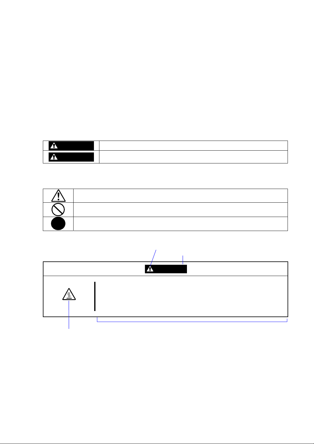
(Example)
High temperature.
Term indicating a degree of danger
Symbol indicating a prohibited
action (may not always be
indicated)
Indicates a danger that could lead to a death or serious injury.
Indicates a danger that could lead to a burn, other injuries or damage to
physical assets.
Symbol to draw attention
CAUTION
Immediately after the power-off, system components such as hard disk are
very hot. Wait the server to cool down completely before adding/removing
some component.
Description of a danger
Page 4
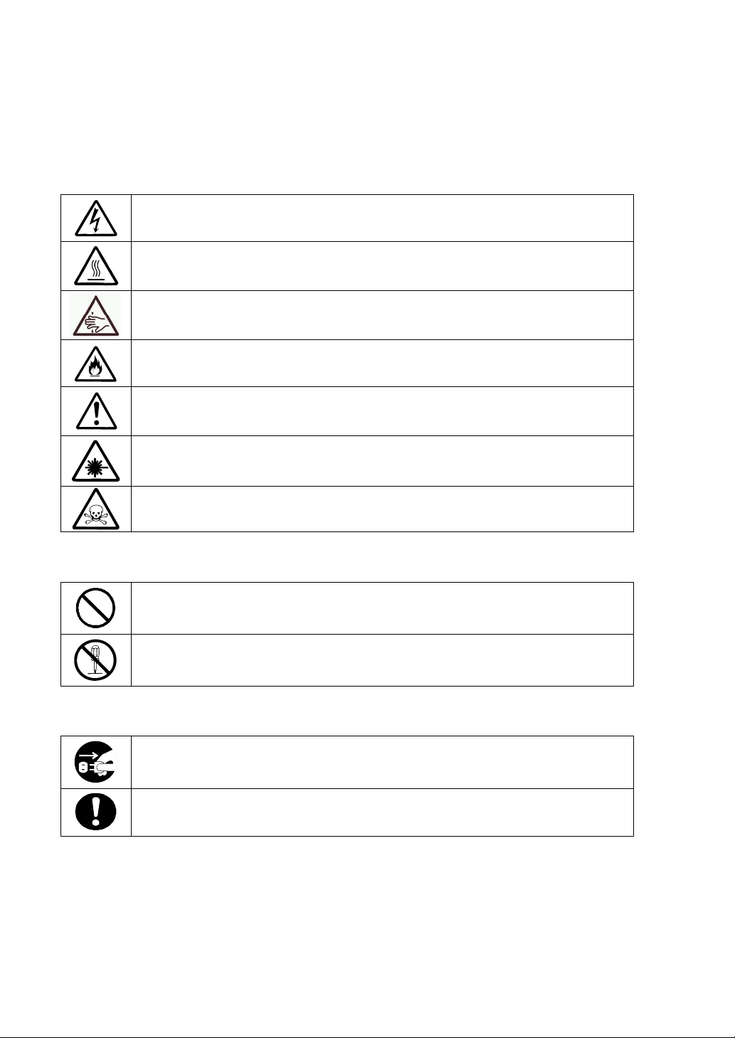
SYMBOLS USED IN THIS USER'S GUIDE AND WARNING LABELS
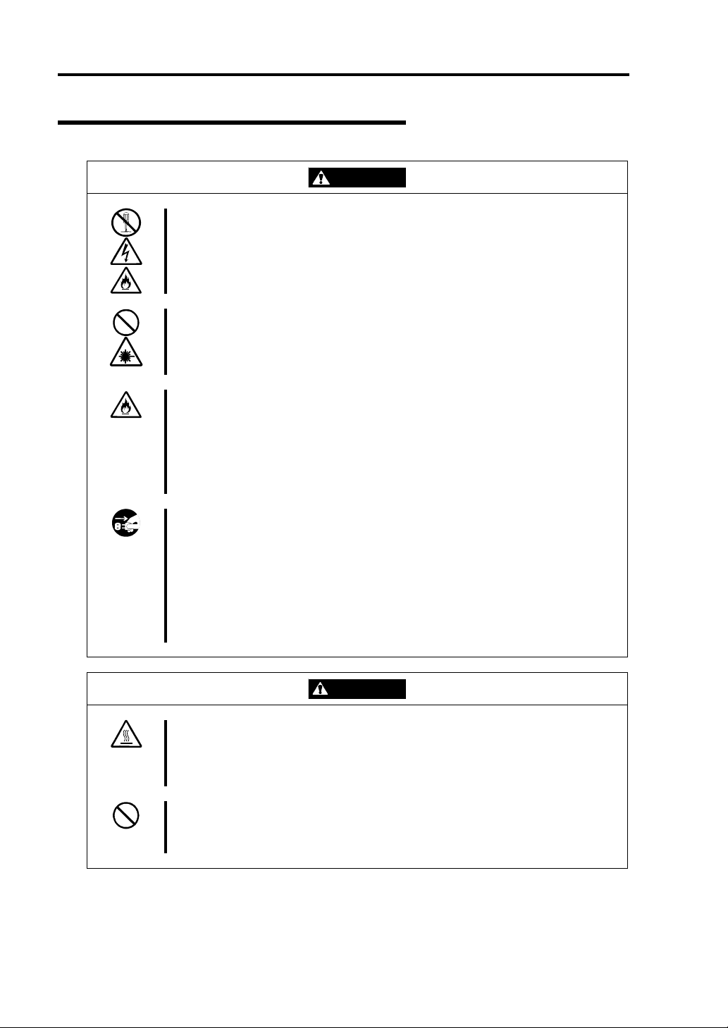
Attention
Indicates a risk of an electric shock.
Indicates a risk of an injury due to heat.
Indicates a risk of catching your fingers.
Indicates a risk of a fire or smoke.
Indicates a general precaution or warning that is not defined herein.
Indicates a risk of losing eyesight due to laser beam.
Indicates a risk of an injury or damage to physical assets due to a hazardous material.
Prohibited actions
Indicates a general prohibition that is not defined herein.
Do not disassemble, repair, or modify the equipment. Otherwise, there is a risk of an
electric shock or fire.
Mandatory actions
Unplug the server. Otherwise, there is a risk of an electric shock or fire.
Indicates a general action to take that is not defined herein. Make sure to follow the
instructions.
Page 5
NOTE: This equipment has been tested and found to comply with the limits for a Class A digital
device, pursuant to Part 15 of the FCC Rules. These limits are designed to provide reasonable
protection against harmful interference when the equipment is operated in a commercial
environment. This equipment generates, uses, and can radiate radio frequency energy and, if not
installed and used in accordance with the instruction manual, may cause harmful interference to
radio communications. Operation of this equipment in a residential area is likely to cause harmful
interference in which case the user will be required to correct the interference at his own expense.
This class A digital apparatus meets all requirements of the Canadian Interference-Causing
Equipment Regulations.
Cet appareil numériqeu de la classe A respecte toutes les exigences du Règlement sur le matériel
brouilleur du Canada.
CE Statement
Warning: This is a Class A product. In residential environment, this product may cause radio
interference, in which case the user may be required to take adequate measures (EN55022).
NOTE: This product provides resistance against hardware faults with its redundant hardware
modules. However, this does not mean complete fault-tolerance is assured. For example,
there is a risk of system down when:
– A fatal fault occurs in software.
– Both modules within a redundant hardware pair break down.
– A fatal fault occurs in a non-redundant component, such as the clock generator circuitry
or the interconnect backplane.
– The entire system is cut off from AC power.
Page 6

Trademarks
NEC ESMPRO, NEC EXPRESSBUILDER, and NEC Express5800/ft series are trademarks of NEC
Corporation. Microsoft, Windows, Windows NT, and MS-DOS are registered trademarks of
Microsoft Corporation in the United States and other countries.
Intel and Pentium are registered trademarks of Intel Corporation. Xeon is a trademark of Intel
Corporation in the United States. Adobe, the Adobe logo, Acrobat, and the Acrobat logo are
trademarks of Adobe Systems Incorporated. AT is a registered trademark of International Business
Machines Corporation in the United States and other countries. Stratus is a registered trademark of
Stratus Technologies Bermuda Ltd. Datalight is a registered trademark of Datalight, Inc. Linux is a
registered trademark of Linus Torvalds. Red Hat and RPM are trademarks or registered trademarks
of Red Hat, Inc. in the United States and other countries.
All other product, brand, or trade names used in this publication are the trademarks or registered
trademarks of their respective trademark owners.
Microsoft Windows Server 2003 Standard Edition operating system and Microsoft Windows Server
2003 Enterprise Edition operating system are called Windows Server for short. Microsoft Windows
2000 Server operating system, Microsoft Windows 2000 Advanced Server operating system and
Microsoft Windows 2000 Professional operating system are called Window s 2000 for short.
Microsoft Windows NT Server network operating system version 3.51/4.0 and Microsoft Windows
NT Workstation operating system version 3.51/4.0 are called Windows NT for short. Microsoft
Windows Millennium Edition Operating System is called Windows Me for short. Microsoft
Windows 98 operating system is called Win dows 98 for short. Microsoft Windows 95 operating
system is called Windows 95 for short.
Names used with sample applications are all fictitious. They are unrelated to any existing product
names, names of organizations, or individual names.
DLT and DLTtape are trademarks of Quantum Corporation in the United States. QLogic and its logo
are trademarks of QLogic Corporation in the United States. Fast!UTIL is a trademark of QLogic
Corporation in the United States. ROM-DOS is a trademark of Datalight, Inc.
Most of the software used for this server can be redistributed freely under the terms of the BSD
Copyright and the GNU Public License. However, some software requires permissions for
redistribution as the owners have ownership. For details, see “Introduction” in the attachment.
To prevent voltage sag:
This product may be affected by voltage sag caused due to lightning. To prevent voltage sag, you
are recommended to use an AC uninterruptible power supply (UPS) unit.
Notes:
(1) No part of this manual may be reproduced in any form without prior written permission of
NEC Corporation.
(2) The contents of this manual are subject to change without prior notice.
(3) The contents of this manual shall not be copied or altered without prior written permission of
NEC Corporation.
(4) All efforts have been made to ensure the accuracy of all information in this manual. If you find
any part unclear, incorrect, or omitted in this manual, contact the sales agent where you
purchased this product.
(5) NEC assumes no liability arising from the use of this product, nor any liability for incidental or
consequential damage arising from the use of this manual regardless of (4) above.
Page 7

PREFACE
Welcome to the NEC Express5800/ft series.
NEC Express5800/ft series is a “fault-tolerant (ft)” server focusing on “high reliability” in terms of
fault-tolerance, in addition to “high performance,” “scalability,” and “general versatility” provided
by NEC Express5800 series. In the event of trouble, its dual configuration will allow the system to
instantaneously isolate the failed parts to assure non-stop running; operation will be moved
smoothly from one module to the other, minimizing damage to it. You can use this NEC
Express5800/ft series in a mission-critical system where high availability is required. By the use of
Linux operating system, it also provides outstanding openness for general-purpose applications, etc.
To make the best use of these features, read this User's Guide thoroughly to understand how to
operate NEC Express5800/ft series.
i
Page 8

ii
ABOUT THIS USER'S GUIDE
This User's Guide helps a user to properly setup and use the product.
Consult this guide to ensure safety as well as to cope with trouble during a system setup and daily
operation.
Keep this manual handy.
This User's Guide is intended for users who have a goo d kn owl e dge on the basic use of Linux
operating systems and general I/O devices such as a keyboard and mouse.
How to Use This User's Guide
This guide consists of eight chapters and appendices. To help you find a solution quickly, the guide
contains the following information:
For descriptions on setting up this product, see the separate volume “User’s Guide (Setup)”.
Read “Precautions for Use” first.
Before going on to main chapters, be sure to read “Precautions for Use.” These precautions are very
important for using the product safely.
Chapter 1 Precautions for Use
This chapter describes precautions necessary to use the product safely and properly. Be
sure to read this chapter before using the product. It also provides information on user
support. It will be helpful when you need maintenance service, support, etc.
Chapter 2 General Description
This chapter describes what you should know about the product: its component names,
functions, operating procedures as well as handling of devices and other parts.
Chapter 3 Linux Setup and Operation
This chapter describes setup and operation specific to the product when it is on Linux.
Chapter 4 System Configuration
This chapter describes how to make settings of built-in basic input/output system. It also
describes factory-shipped parameters.
Chapter 5 Installing and Using Utilities
This chapter describes features and operating procedures of a standard utility “NEC
EXPRESSBUILDER.” It also describes procedures to install and operate various
software programs contained in its CD-ROM.
Chapter 6 Maintenance
This chapter describes maintenance procedures and use of maintenance tools. If you
need to move the product for maintenance purposes, follow the steps provided in this
chapter.
Chapter 7 Troubleshooting
If the product does not work properly, see this chapter before deciding that it is a
breakdown.
Chapter 8 System Upgrade
This chapter describes procedures to add options and precautions. See also this chapter
when you replace failed components.
Appendix A Specifications
This appendix lists specifications of the product.
Appendix B I/O Port Addresses
This appendix lists factory-assigned I/O port addresses.
Page 9

Additional symbols
The following symbols are used throughout this User's Guide in addition to the caution symbols
describe at the beginning.
iii
IMPORTANT:
CHECK:
TIPS:
Important points or instructions to keep in mind when using the
server or software
Something you need to make sure when using the server of
software
Helpful information, something useful to know
Accessories
This product is shipped with various accessories. See the attached list to make sure everything is
included and check the individual items. If some component is missing or damaged, contact your
sales agent.
Keep the accessories in a safe place. You will need them when you perform setup,
addition of options, or replacement of failed components.
To check NEC EXPRESSBUILDER components, see the attached list.
Be sure to fill out and mail the software registration card that is attached to your operating
system.
Make backup copies of included floppy disks, if any. Keep the original disks as the master
disks; use these copies in operation.
Improper use of an included floppy disk or CD-ROM may alter your system environment.
If you find something unclear, stop using them and contact your sales agent.
Page 10

iv
(This page is intentionally left blank.)
Page 11

v
CONTENTS
PREFACE.........................................................................................................................................i
ABOUT THIS USER'S GUIDE......................................................................................................ii
Chapter 1 Precautions for Use..................................................................................... 1-1
WARNING LABELS ...................................................................................................................1-2
Tower Model ............................................................................................................................1-2
Rack-mount Model...................................................................................................................1-4
PCI/CPU Modules....................................................................................................................1-6
PRECAUTIONS FOR SAFETY..................................................................................................1-8
General.....................................................................................................................................1-8
Use of Power Supply and Power Cord.....................................................................................1-9
Installation, Relocation, Storage and Connection...................................................................1-10
Cleaning and Handling of Internal Devices ...........................................................................1-12
During Operation ...................................................................................................................1-13
Rack-mount Model.................................................................................................................1-14
For Proper Operation..............................................................................................................1-15
TRANSFER TO THIRD PARTY...............................................................................................1-17
DISPOSAL OF EQUIPMENT AND CONSUMABLES ...........................................................1-18
IF SYSTEM TROUBLE IS SUSPECTED.................................................................................1-19
ABOUT REPAIR PARTS...........................................................................................................1-19
Chapter 2 General Description ....................................................................................2-1
STANDARD FEATURES ............................................................................................................2-2
NAMES A ND FUNCTIONS OF COMPONENTS......................................................................2-6
Front Vi ew................................................................................................................................2-6
Front View (inside)...................................................................................................................2-8
CD- ROM Drive.......................................................................................................................2-9
Rear Vie w...............................................................................................................................2-10
CPU Module...........................................................................................................................2-12
PCI Module............................................................................................................................2-14
Chassis Board Layout.............................................................................................................2-15
LEDs ......................................................................................................................................2-16
BASIC OPERATION.................................................................................................................2-28
Locking and Unlocking the Front Bezel ................................................................................2-28
Power ON...............................................................................................................................2-30
Power OFF.............................................................................................................................2-31
POST Check...........................................................................................................................2-32
Floppy Disk Drive..................................................................................................................2-35
CD-ROM Drive......................................................................................................................2-37
Chapter 3 Linux Setup and Operation ........................................................................ 3-1
HARD DISK CONFIGURATIONS THAT CAN BE BUILT ON THE NEC Express5800/ft
series.............................................................................................................................................3-2
REPLACING 3.5-INCH HARD DISK DRIVE...........................................................................3-4
How to Locate Failed Disks.....................................................................................................3-4
Restoring Redundant Configuration Manually.........................................................................3-6
Page 12

vi
Chapter 4 System Configuration .................................................................................4-1
SYSTEM BIOS ~ SETUP ~........................................................................................................ 4-2
Starting SETUP Utility............................................................................................................ 4-3
Description of On-Screen Items and Key Usage..................................................................... 4-4
Configuration Examples..........................................................................................................4-5
Menu and Parameter Descriptions........................................................................................... 4-8
SCSI BIOS ∼ Fast!UTIL ∼ ........................................................................................................ 4-29
Start ....................................................................................................................................... 4-29
Configuration Settings........................................................................................................... 4-32
Scan SCSI Bus....................................................................................................................... 4-36
SCSI Disk Utility................................................................................................................... 4-36
Select Host Adapter............................................................................................................... 4-36
Exit Fast!UTIL ∼ Termination and Storage of Fast!UTIL ∼ ................................................. 4-37
Setting List for Optional SCSI Device .................................................................................. 4-37
FORCED SHUTDOWN AND CLEAR..................................................................................... 4-38
Forced Shutdown................................................................................................................... 4-38
Clear CMOS / Password (Configuring Motherboard Jumpers)............................................. 4-39
Chapter 5 Installing and Using Utilities.......................................................................5-1
NEC EXPRESSBUILDER.......................................................................................................... 5-2
Start Menu............................................................................................................................... 5-2
NEC EXPRESSBUILDER Top Menu .................................................................................... 5-4
Consoleless Menu.................................................................................................................... 5-7
Master Control Menu .............................................................................................................. 5-9
NEC ESMPRO Agent and Manager.......................................................................................... 5-10
Overview............................................................................................................................... 5-10
NEC ESMPRO Agent............................................................................................................ 5-18
NEC ESMPRO Manager....................................................................................................... 5-23
Maintenance of NEC Express5800/ft series.......................................................................... 5-36
NEC MWA ∼ MANAGEMENT WORKSTATION APPLICATION ∼ ..................................... 5-56
Servers to be remotely managed by MWA............................................................................ 5-56
Remote Management Configuration for the Server without Console.................................... 5-57
Chapter 6 Maintenance.................................................................................................6-1
DAILY MAINTENANCE........................................................................................................... 6-2
Checking Alert......................................................................................................................... 6-2
Checking STATUS LEDs and LCD Display ........................................................................... 6-2
Making Backup Copies ........................................................................................................... 6-3
Cleaning................................................................................................................................... 6-3
SYSTEM DIAGNOSTICS.......................................................................................................... 6-7
Test Items................................................................................................................................. 6-7
Startup and Exit of System Diagnosis..................................................................................... 6-7
OFF-LINE MAINTENANCE UTILITY..................................................................................... 6-9
Starting the Off-line Maintenance Utility................................................................................ 6-9
Features of Off-line Maintenance Utility................................................................................. 6-9
RELOCATING/STORING THE NEC Express5800/ft series.....................................................6-11
Page 13

vii
Chapter 7 Troubleshooting.......................................................................................... 7-1
TO LOCATE THE ERRORS........................................................................................................7-2
ERROR MESSAGES...................................................................................................................7-3
Error Messages by LED Indication..........................................................................................7-3
Error Messages on the Liquid Crystal Display (LCD).............................................................7-3
POST Error Messages............................................................................................................7-14
Error Notification by BEEP ...................................................................................................7-20
Linux Error Messages............................................................................................................7-21
Server Management Application Error Message....................................................................7-23
SOLVING PROBLEMS.............................................................................................................7-24
Problems with NEC Express5800/ft series.............................................................................7-24
Event Log...............................................................................................................................7-31
Problems with NEC EXPRESSBUILDER ............................................................................7-33
Problems with Master Control Menu.....................................................................................7-34
Problems with NEC ESMPRO............................................................................................... 7-35
COLLECTION OF TROUBLE LOGS ......................................................................................7-36
Collection of syslog................................................................................................................7-36
Collection of System Information..........................................................................................7-36
Collection of the Memory Dump ...........................................................................................7-37
Backup of IPMI Information..................................................................................................7-38
Chapter 8 System Upgrade.......................................................................................... 8-1
SAFETY PRECAUTIONS...........................................................................................................8-2
ANTI-STATIC MEASURES........................................................................................................8-3
PREPARING YOUR SYSTEM FOR UPGRADE.......................................................................8-4
3.5-INCH HARD DISK DRIVE..................................................................................................8-5
Installing 3.5-inch Hard Disk Drive.........................................................................................8-7
Removing 3.5-inch Hard Disk Drive........................................................................................8-9
Replacing 3.5-inch Hard Disk Drive......................................................................................8-10
RAID CONFIGURATION WHEN DISKS ARE ADDED ........................................................8-11
CPU MODULE..........................................................................................................................8-13
Removing CPU Module.........................................................................................................8-14
Installing CPU Module...........................................................................................................8-16
DIMM.........................................................................................................................................8-18
Installing DIMM ....................................................................................................................8-20
Removing DIMM...................................................................................................................8-21
Replacing DIMM...................................................................................................................8-22
PROCESSOR (CPU)..................................................................................................................8-23
Installation..............................................................................................................................8-24
Removing CPU ......................................................................................................................8-27
Replacing CPU.................................................................................................................. .....8-28
PCI MODULE............................................................................................................................8-29
Precautions.............................................................................................................................8-30
Removing PCI Module...........................................................................................................8-31
Installing PCI Module............................................................................................................8-33
PCI BOARD...............................................................................................................................8-35
Installing PCI Board...............................................................................................................8-36
Removing PCI Board.............................................................................................................8-41
Replacing PCI Board..............................................................................................................8-42
Page 14

viii
Setup of Optional PCI Board................................................................................................. 8-43
Appendix A Specifications .......................................................................................... A-1
Appendix B I/O Port Address...................................................................................... B-1
Page 15

Chapter 1
Precautions for Use
This chapter includes information necessa ry fo r pr o per and safe operation of the server.
Page 16
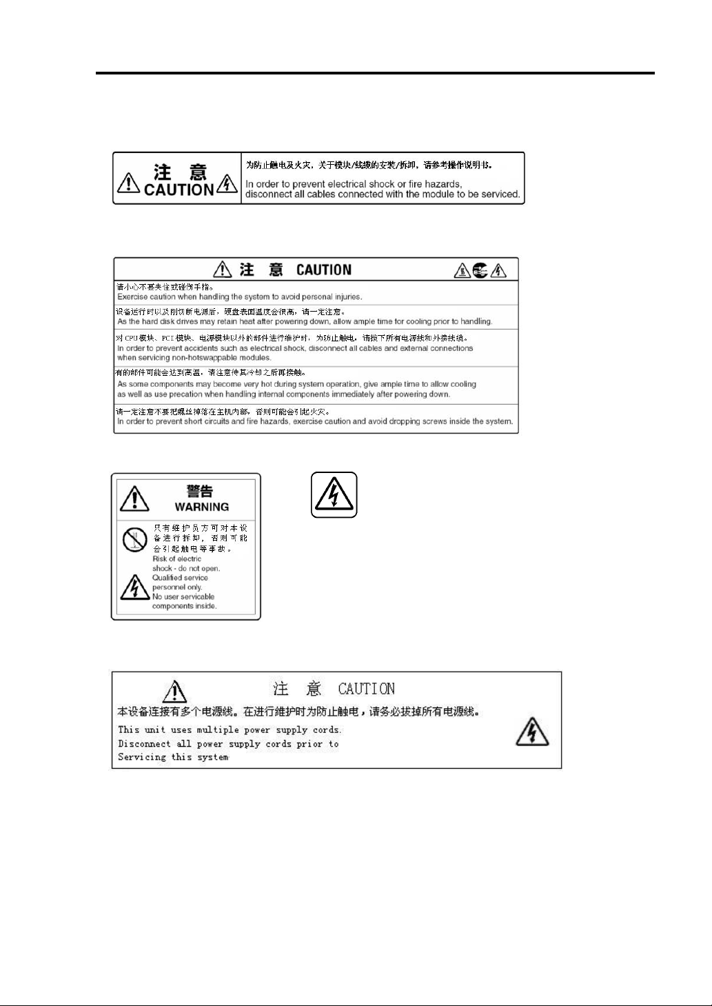
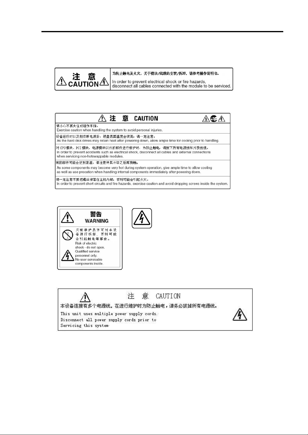
1-2 Precautions for Use
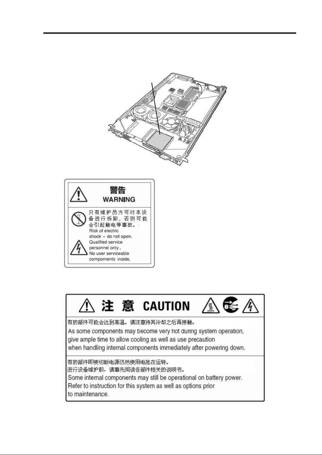
WARNING LABELS
Warning labels are placed in certain parts of the system so that the user stays alert to possible risks
(Do not remove or damage these labels).
If some label is missing, about to peel off, or illegible, contact your sales agent.
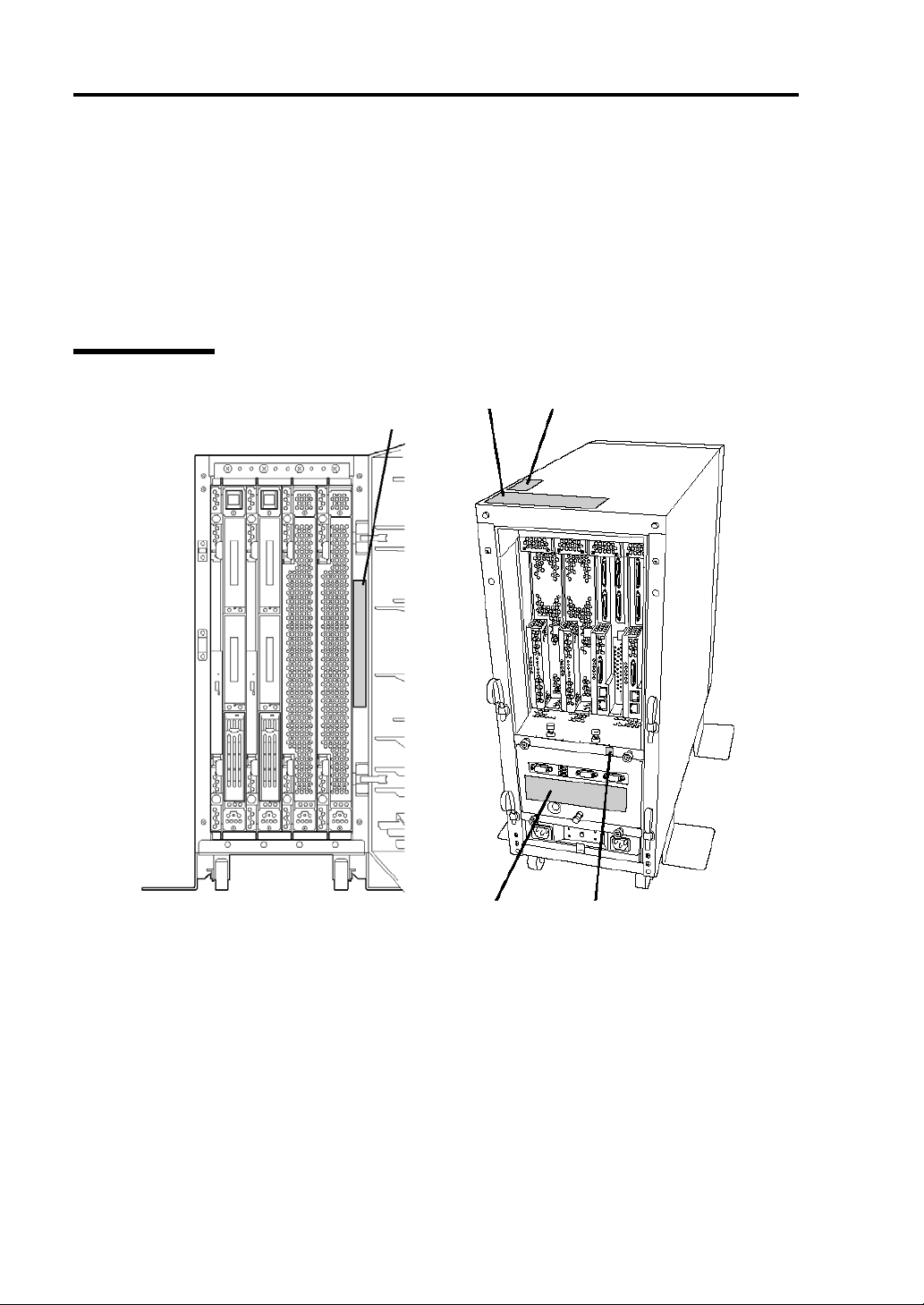
The figures below show locations of the labels on tower model and rack-mount model servers.
Tower Model
Label A
Label B
Label C
Label D Label E
Page 17
Precautions for Use 1-3
Label A
Label B
Label C
Label D
Label E
Page 18
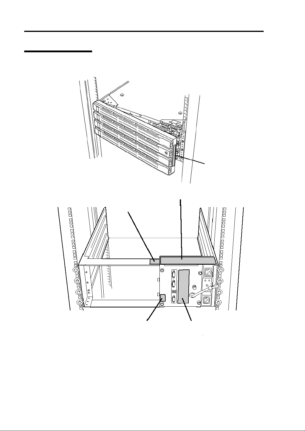
1-4 Precautions for Use
Rack-mount Model
Label A
Label B
Label C
Label E Label D
Page 19
Precautions for Use 1-5
Label A
Label B
Label C
Label D
Label E
Page 20
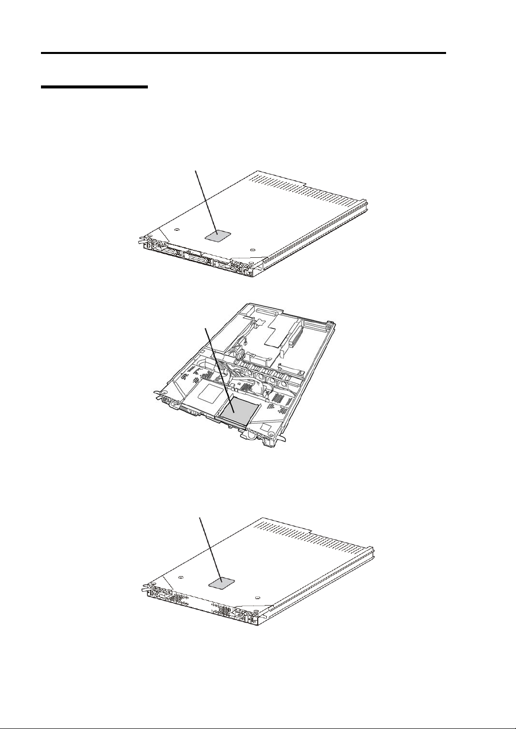
1-6 Precautions for Use
PCI/CPU Modules
PCI Module
External View
Internal View
Label A
Label B
CPU Module
External View
Label A
Page 21
Precautions for Use 1-7
Label B
Internal View
Label A
Label B
Page 22
1-8 Precautions for Use
PRECAUTIONS FOR SAFETY
This section provides precautions for using the server safely. Read this section carefully to ensure
proper and safe use of the server. For symbol meanings, see "SAFETY INDICATIONS" described
in the previous section.
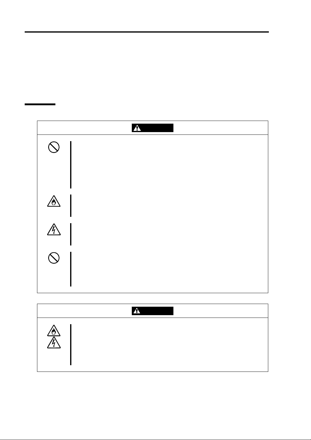
General
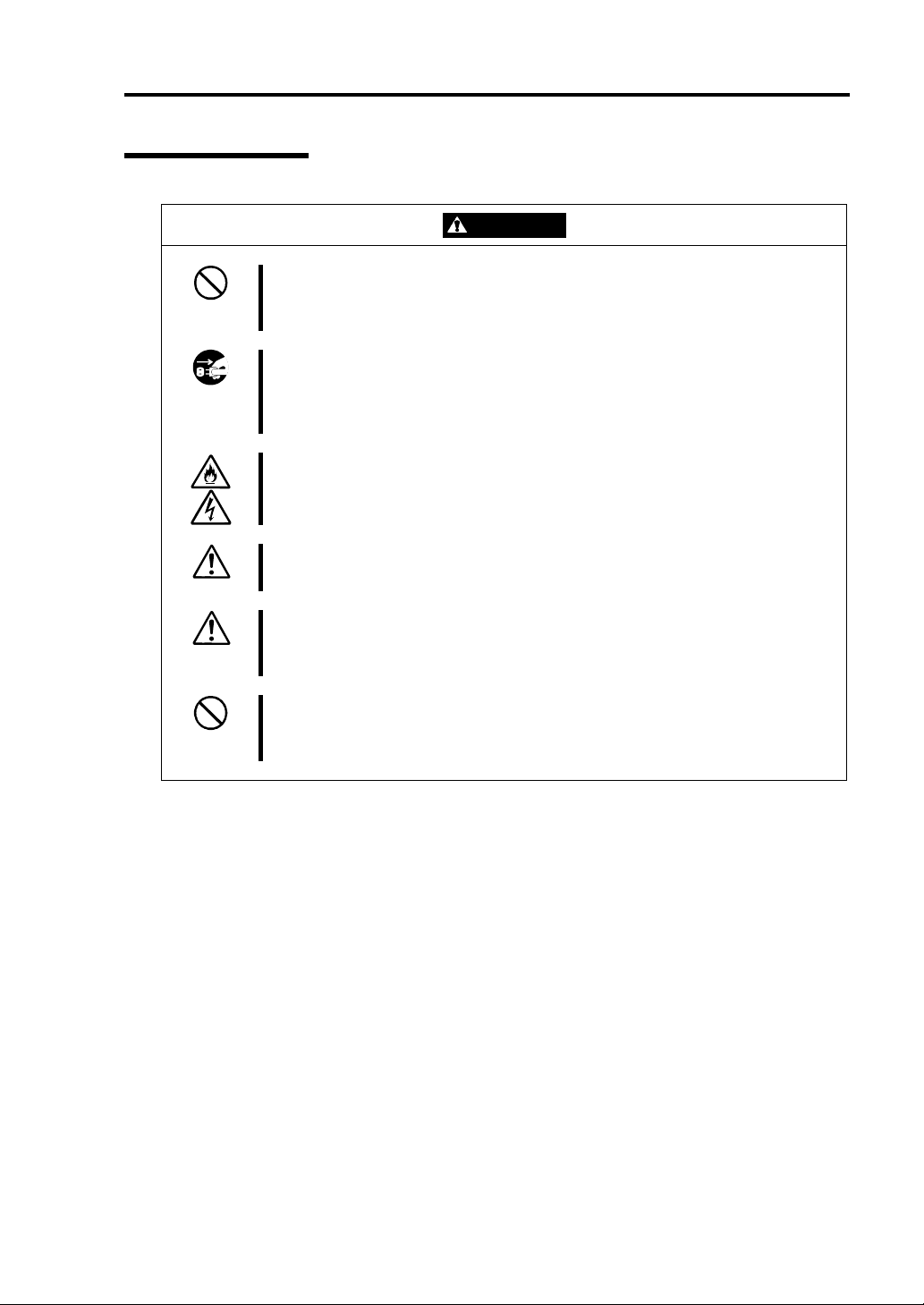
WARNING
Do not use the equipment in an operation where human lives are involved or
high reliability is required.
This equipment is not intended for use in controlling or use with facilities or
systems where human lives are involved or high reliability is required, inc luding
medical devices or nuclear, aerospace, transportation, and traffic control
facilities. NEC assumes no liability for any accidents or damage to physical
assets resulting from the use of this equipment in such systems or facilities.
Do not continue to use the equipment if you detect smoke, odor, or noise.
If the equipment emits smoke, odor, or noise, immediately flip off the POWER
switch, unplug the cord, and contact your sales agent. There is a risk of a fire.
Do not insert a wire or metal object
Do not insert a wire or metal objects into a vent or disk drive slot. There is a risk
of an electric shock.
Do not use the equipment in an unsuitable place.
Do not install a server rack in an unsuitable environment.
Other systems also may be affected, and the rack may fall over to cause a fire
or injuries. For details about installation environment and quake-resistant
engineering, see the attached manual or contact your sales agent.
Prevent water or foreign objects from getting into the equipment.
Do not let water or foreign objects (e.g., pins or paper clips) enter the
equipment. There is a risk of a fire, electric shock, and breakdown. When such
things accidentally enter the equipment, immediately turn off the power and
unplug the cord. Contact your sales agent instead of trying to disassemble it
yourself.
CAUTION
Page 23
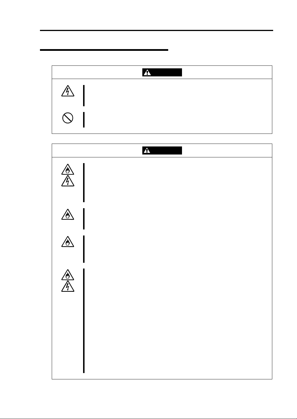
Use of Power Supply and Power Cord
Precautions for Use 1-9
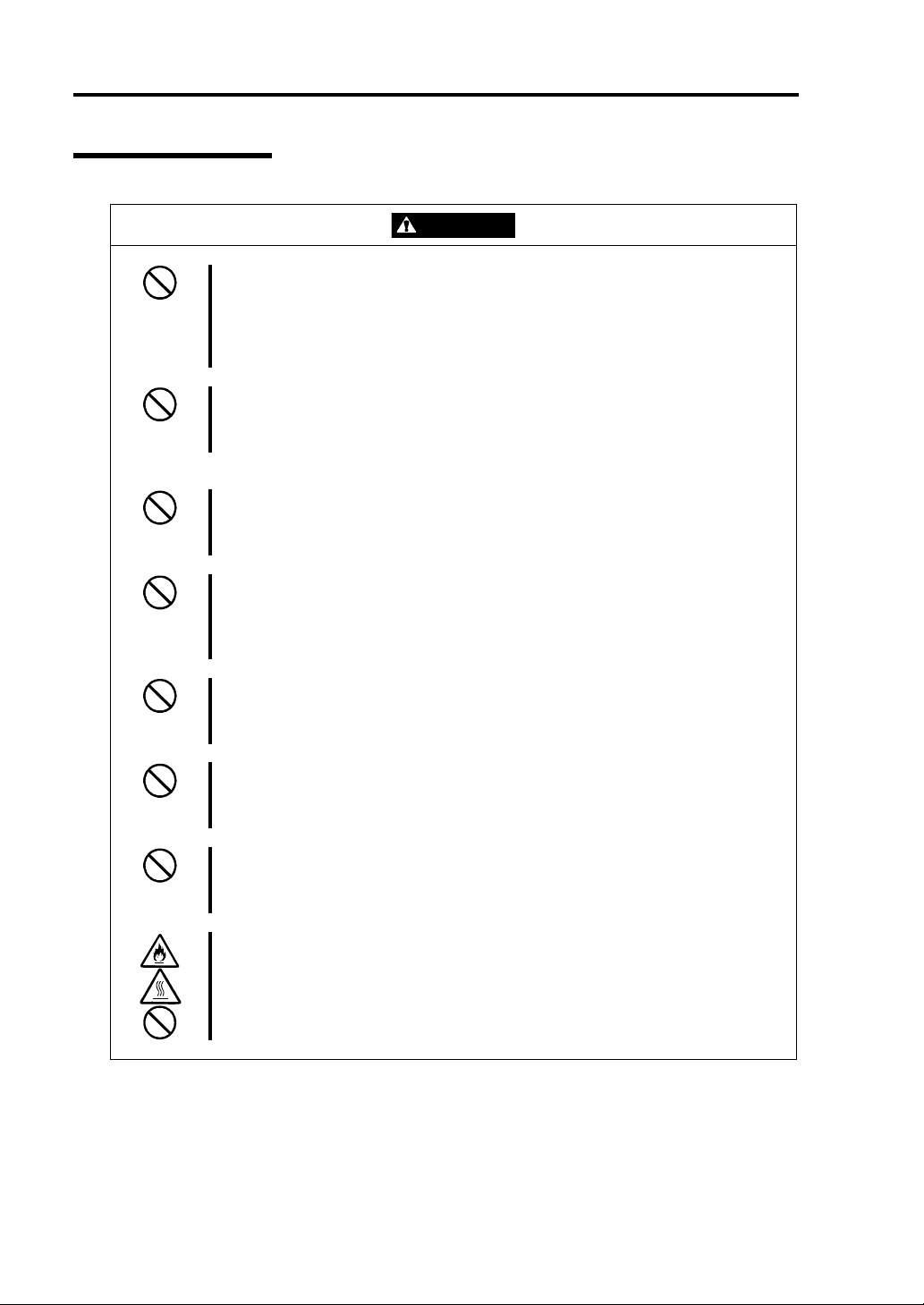
WARNING
Do not handle a power plug with a wet hand.
Do not plug/unplug a power cord with a wet hand. There is a risk of an electric
shock.
Do not connect the ground wire to a gas pipe.
Never connect the ground wire to a gas pipe. There is a risk of a gas explosion.
CAUTION
Do not plug the cord in a nonconforming outlet.
Use a wall outlet with specified voltage and power type. There is a risk of a fire
or current leakage.
Avoid installing the equipment where you may need an extension c ord. If the
cord that does not meet the power specifications, there is a risk of overheating
that could lead to a fire.
Do not plug too many cords in a single outlet.
If the rated current is exceeded, there is a risk of overheating that could lead to
a fire.
Do not plug the cord insecurely.
Insert the plug firmly into an outlet. There is a risk of heat or fire due to poor
contact. If dust settles on the slots and it absorbs moisture, there is also a risk
of heat or fire.
Do not use nonconforming power cords.
Use the power cords specified by NEC. If the rated current is exceeded, there is
a risk of a fire.
You also have to observe the following prohibitions to prevent an electric shock
and a fire caused by damages of the cords.
Do not pull on the cord.
Do not pinch the cord.
Do not bend the cord.
Keep chemicals away from the cord.
Do not twist the cord.
Do not tread on the cord.
Do not place any object on the cord.
Do not use cords as bundled.
Do not alter, modify, or repair the cord.
Do not staple the cord.
Do not use any damaged cord. (Replace it with a new one of the same
specifications. For replacement procedures, contact your sales agent.)
Page 24
1-10 Precautions for Use
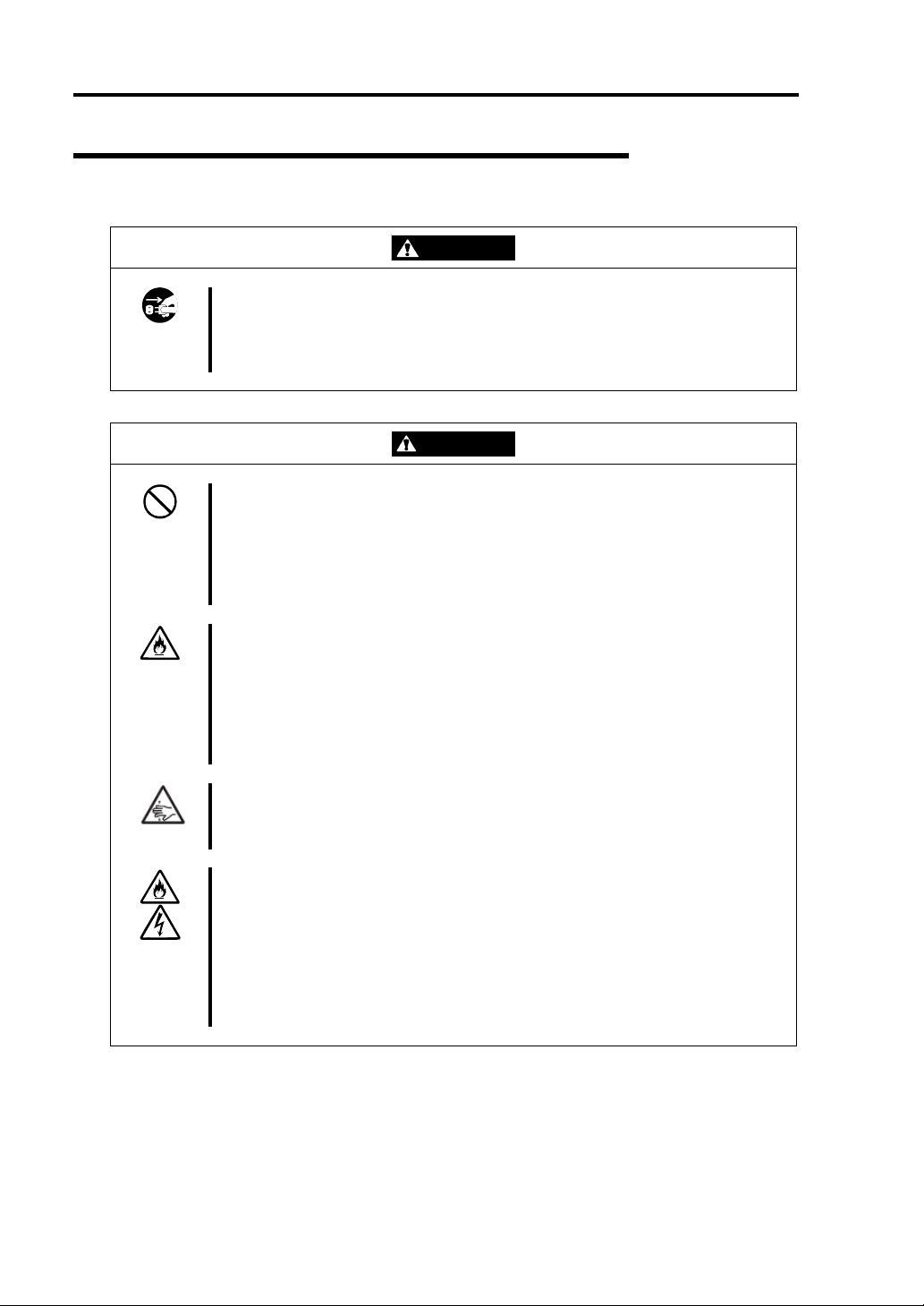
Installation, Relocation, Storage and Connection
Disconnect the power cord(s) before installing or removing the equipment.
Be sure to power off the equipment and unplug its power cords from the wall
outlet before installation/relocation. All voltage is removed only when the power
cords are unplugged.
WARNING
Do not hold the front bezel to lift the equipment.
The equipment weighs around 70 kg (depending on its hardware configuration).
Do not hold the front bezel, or it may become detached, causing an injury. For
lifting and moving the equipment, remove the mounted modules from the main
unit and carry them separately. It takes at least two people to carry it; hold the
equipment firmly by its bottom.
Do not install or store the equipment in an unsuitable place.
Install or store the equipment in such a place as specified in this User's Guide.
Avoid the following, or there is a risk of a fire.
a dusty place
a humid place located near a boiler, etc
a place exposed to direct sunlight
an unstable place
Be careful not to hurt your fingers.
Exercise great care not to hurt your fingers on the rail when you
mount/dismount the equipment into/from the rack.
Do not connect any interface cable with the power cord of the server plugged to
a power source.
Make sure to power off the server and unplug the power cord from a power
outlet before installing/removing any optional internal device or
connecting/disconnecting any interface cable to/from the server. If the server is
off-powered but its power cord is plugged to a power source, touching an
internal device, cable, or connector may cause an electric shock or a fire
resulted from a short circuit.
CAUTION
Page 25
Precautions for Use 1-11
CAUTION
Do not use any non-designated interface cable.
Use only interface cables designated by NEC; identify which component or
connector to attach beforehand. If you use a wrong cable or make a wrong
connection, there is a risk of short-circuit that could lead to a fire.
You also have to observe the following prohibitions about handling and
connecting interface cables:
Do not use any damaged cable connector.
Do not step on the cable.
Do not place any object on the cable.
Do not use the equipment with loose cable connections.
Do not use or store this product in corrosive environment.
Avoid the usage or storage of this product in an environment which may be
exposed to corrosive gases, such as those including but not limited to :
sulfur dioxide, hydrogen sulfide, nitrogen dioxide, chlorine, ammonia and/or
ozone.
Avoid installing this product in a dusty environment or one that may be exposed
to corrosive materials such as sodium chloride and/or sulfur.
Avoid installing this product in an environment which may have excessive metal
flakes or conductive particles in the air.
Such environments may cause corrosion or short circuits within this product,
resulting in not only damage to this product, but may even lead to be a fire
hazard.
If there are any concerns regarding the environment at the planned site of
installation or storage, please contact your sales agent
Page 26
1-12 Precautions for Use
Cleaning and Handling of Internal Devices
WARNING
Do not disassemble, repair, or alter the server.
Unless described herein, never attempt to disassemble, repair, or alter the
equipment. There is a risk of an electric shock or fire as well as malfunction.
Do not look into the CD-ROM drive
The CD-ROM drive uses a laser beam. Do not look or insert a mirror inside
while the system is on. A laser beam is invisible; if your eyes get exposed to it,
there is a risk of losing eyesight.
Do not detach a lithium battery yourself.
This equipment has a lithium battery. Do not detach it yourself. If the battery is
exposed to fire or water, it could explode.
When the lithium battery is running down and the equipment doesn’t work
correctly, contact your sales agent instead of disassembling, replacing or
recharging it yourself.
Disconnect the power plug before cleaning the server.
Make sure to power off the server and disconnect the power plug from a power
outlet before cleaning or installing/removing internal optional devices. Touching
any internal device of the server with its power cord connected to a power
source may cause an electric shock even of the server is off-powered.
Disconnect the power plug from the outlet occasionally and clean the plug with
a dry cloth. Heat will be generated if condensation is formed on a dusty plug,
which may cause a fire.
High temperature
Immediately after powering off the system, system components such as hard
disk may be very hot. Wait for the server to cool down completely before
adding/removing components.
Make sure to complete installation.
Firmly install all power cords, interface cables and/or boards. An incompletely
installed component may cause a contact failure, resulting in fire and/or smoke.
CAUTION
Page 27
During Operation
Precautions for Use 1-13
Do not pull out a device during operation.
Do not pull out or remove a device while it works. There is a risk of malfunction
and injuries.
Do not touch the equipment when it thunders.
Unplug the equipment when it threatens to thunder. If it starts to thunder before
you unplug the equipment, do not touch the equipment and cables. There is a
risk of a fire or electric shock.
Keep animals away.
Animal’s waste or hair may get inside the equipment to cause a fire or electric
shock.
Do not place any object on top of the server.
The object may fall off to cause injuries, damage to hardware and/or a fire.
Do not leave the CD tray ejected.
Dust may get in the equipment to cause malfunction. The ejected tray may also
become a cause of injuries.
Do not use a cellular phone or pager around the equipment.
Turn off your cellular phone or pager when you use the equipment. Their radio
waves may cause the equipment to malfunction.
CAUTION
Page 28
1-14 Precautions for Use
Rack-mount Model
CAUTION
Do not install the equipment on a nonconforming rack.
Install the equipment on a 19-inch rack confirming to the EIA standard. Do not
use the equipment without a rack or install it on a nonconforming rack. The
equipment may not function properly, and there is a risk of damage to physical
assets or injuries. For suitable racks, contact your sales agent.
Do not attempt to install the server yourself.
To avoid a risk of injuries, users should not attempt to install the equipment into
a rack. Installation should be performed by trained maintenance personnel.
< For Maintenance Personnel Only >
Do not remove and carry the equipment with modules mounted.
When you remove this product from the rack and carry it, remove all modules
that are mounted first.
Do not install the equipment in such a manner that its weight is imposed on a
single place.
To distribute the weight, attach stabilizers or install two or more racks. It may
fall down to cause injuries.
Do not assemble parts alone.
It takes at least two people to mount doors and trays to a rack. You may drop
some parts to cause a breakage or injuries.
Do not pull a device out of the rack if it is unstable.
Before pulling out a device, make sure that the rack is fixed (by stabilizers or
quake-resistant engineering).
Do not leave two or more devices pulled out from the rack.
If you pull out two or more devices the rack may fall down. You can only pull out
one device at a time.
Do not install excessive wiring.
To prevent burns, fires, and damage to the equipment, make sure that the rated
load of the power branch circuit is not exceeded. For more information on
installation and wiring of power-related facilities, contact your electrician or local
power company.
Page 29

Precautions for Use 1-15
For Proper Operation
Observe the following instructions for successful operation of the server. Failure to observe them
could lead to malfunction or breakdown.
Perform installation in a place where the system can operate correctly. For details, see the
separate volume “User’s Guide (Setup)”.
Before turning off the power or ejecting a disk, make sure that the access LED is off.
When you have just turned off the power, wait at least 30 seconds before turning it on again.
Once you have turned on the server, do not turn it off until the "NEC" logo appears on the
screen.
Before you move the equipment, turn off the power and unplug the cord .
This server shall not assure reproduction of copy-protect CDs using reproduction equipment
if such disks do not comply with CD standards.
Clean the equipment regularly. (For procedures, see Chapter 6.) Regular cleaning is effective
in preventing various types of trouble.
Lightning may cause voltage sag. As a preventive measure, it is recommended to use UPS
(uninterruptible power supply).
This equipment does not support the connection through an UPS serial port (RS-232C) or the
control using PowerChutePlus .
Check and adjust the system clock before operation in the following conditions:
- After transporting the equipment
- After storing the equipment
- After the equipment halt under the conditions which is out of the guranteed
environment conditions (Temperature: 10 to 35
°C, Humidity: 20 to 80%).
Check the system clock once in a month. It is recommended to operate the system clock using
a time server (NTP server) if it is installed on the system which requires high level of time
accuracy. If the system clock goes out of alignment remarkably as time goes by, though the
system clock adjustment is performed, contact your sales agent.
When you store the equipment, keep it under storage environment conditions (Temperature:
-10 to 55°C, Humidity: 20 to 80%, non-condensing).
If NEC Express5800/ft series, the built-in optional devices, and the media set for the backup
devices (tape cartridges) are moved from a cold place to a warm place in a short time,
condensation will occur and cause malfunctions and breakdown when these are used in such
state. In order to protect important stored data and assets, make sure to wait for a sufficient
period of time to use the server or components in the operating environment.
Reference: Length of the time effective at avoiding condensation in winter (more than 10°C
differences between room temperature and atmospheric temperature)
Disk devices: Approximately 2-3 hours
Tape media: Approximately 1 day
Make sure that the optional devices are attachable and connectable to the equipment. There is
a risk of malfunctions that could lead to a breakdown of the equipment even if you could
attach and connect.
Page 30

1-16 Precautions for Use
Make sure that your options are compatible with the system. If you attach any incompatible
option, there is a risk of malfunction that could lead to a breakdown.
It is recommended to use NEC's genuine option products. Some competitors’ products are
compatible with this server. However, servicing for trouble or damage resulting from such a
product will be charged even within the warranty period.
Page 31

Precautions for Use 1-17
TRANSFER TO THIRD PARTY
When you transfer (or sell) the product or its included items, you must observe the following:
Server
Attach this User's Guide to the server you are transferring (or selling) to a third party.
IMPORTANT: Data remaining on hard disk:
When you transfer your server, you are responsible for erasing important data stored on its
hard disk (e.g., customer information, accounting information); you must be careful to prevent
such data from leaking out to outsiders.
Even if you execute a “format” command to erase data superficially, the data actually remains
on the hard disk. If data is not erased completely, it could be restored by certain software and
be used for unexpected purposes.
You are strongly recommended to buy a special type of software or service to avoid such
trouble. For details, contact your sales agent.
NEC shall not be accountable for such data leakage caused by your failure to take necessary
measures.
Included Software
When you transfer or sell the included software to a third party, you must meet the following
conditions:
Transfer all of the software included with the system. Do not retain any copies.
Meet the conditions of transfer described in each software license agreement.
Uninstall untransferable programs, if any, from the server before the transfer.
Page 32

1-18 Precautions for Use
DISPOSAL OF EQUIPMENT AND CONSUMABLES
When you dispose of the main unit, hard disk drive, floppy disks, CD-ROMs, optional
boards, etc., you need to observe your local disposal rules. For details, ask your municipal
office.
IMPORTANT: For disposal (or replacement) of batteries on the motherboard,
consult with your sales agent.
If data remains on the hard disk, backup data cartridges, floppy disks, or other
writable media (such as CD-R and CD-RW), it could be restored and reused by
outsiders. The customer is responsible for wiping out such data before disposal. You
need to exercise sufficient care to protect privacy and confidential information.
Some of the system components have limited lifetime (e.g., cooling fans, built-in batteries,
built-in CD-ROM drive, floppy disk drive, mouse). For stable operation, it is
recommended to replace them regularly. For lifetime of individual components and
replacing procedures, ask your sales agent.
WARNING
Do not detach a lithium battery yourself.
This equipment has a lithium battery. Do not detach it yourself. If the battery is
exposed to fire or water, it could explode.
RISK OF EXPLOSION IF BATTERY IS REPLACED WITH INCORRECT TYPE.
DISPOSE OF USED BATTERIES ACCORDING TO THE INSTRUCTIONS.
When the lithium battery is running down and the equipment doesn’t work
correctly, contact your sales agent instead of disassembling, replacing or
recharging it yourself.
PCI module board
Page 33

Precautions for Use 1-19
IF SYSTEM TROUBLE IS SUSPECTED
Before sending the equipment for repair, try the following:
1. Check if its power cord and connection cables are attached correctly.
2. See “Error Messages” in Chapter 7 to check if there is a relevant symptom. If yes, take
measures as instructed.
3. Certain software programs are required for operation of NEC Express5800/ft series.
Check if these programs are properly installed.
4. Use a commercially available anti-virus program to check the server.
If the problem isn’t solved by the above actions, stop using the server and consult with your sales
agent. In this case, check LED indications of the server and alarm indications on the display, which
will serve as helpful information at the time of repair.
ABOUT REPAIR PARTS
The minimum duration of hold ing repair parts of this equipment may be different for each country,
so contact the NEC sales representatives.
If the period is not specified, the repair parts are kept for 5 years aft er di sco nti nuance of the product.
Page 34

1-20 Precautions for Use
Advice for Your Health
Prolonged use of a computer may affect your health. Keep in mind the
following to reduce stresses on your body:
Sit in a good posture
Sit on your chair with your back straight. If the desk height is appropriate,
you will slightly look down at the screen and your forearms will be parallel to
the floor. This “good” work posture can minimize muscle tension caused by
sedentary work.
If you sit in a “bad” posture—for example, sit round-shouldered or with you
face too close to the display—you may easily suffer fatigue or have your
eyesight affected.
Adjust the installation angle of Display
Most types of displays allow you to adjust the angle vertically and
horizontally. This adjustment is very important to prevent the reflection of
light as well as to make the screen more comfortable to see. Without this
adjustment, it is difficult to maintain a “good” work posture and may get tired
soon. Be sure to adjust the angle before using the display.
Adjust Brightness and Contrast
Displays allow you to adjust brightness and contrast. Optimum brightness
and contrast vary depending on the individual, age, brightness of the room,
etc; you need to make an adjustment accordingly. If the screen is too bright
or too dark, it is bad for your eyes.
Adjust the installation angle of Keyboard
Some types of keyboards allow you to adjust the angle. If you adjust the
angle to make the keyboard more comfortable to use, you can greatly
reduce stresses on your shoulders, arms, and fingers.
Clean the Equipment
Cleanliness of the equipment is very important not only for reasons of
appearance but also from the viewpoints of function and safety. Especially,
you need to regularly clean the display, which gets unclear due to the
accumulation of dirt.
Take a break when you get tired
If you feel tired, you are recommended to refresh yourself by taking a short
break or doing a light exercise.
Page 35

Chapter 2
General Description
This chapter describes what you need to know to use the NEC Express5800/ft series. Refer to this
chapter when you want to know about certain components and how to operate them.
Page 36

2-2 General Description
STANDARD FEATURES
High performance
Intel
High-speed Ethernet interface
High-speed disk access (Ultra160 SCSI
Expandability
Wide variety of optional I/O slots
Large memory of up to 6 GB
USB interface
High-reliability Various Features
Memory monitoring feature (1-bit error
Bus parity error detection
Temperature monitoring
Error notification
Built-in fan monitoring feature
Internal voltage monitoring feature
BIOS password feature
Security feature (security lock for front
Management Utilities Maintainability
NEC ESMPRO
NEC Management Workstation
®
Xeon ™ Processor (2.4 GHz)
(1000Mbps/100Mbps/10Mbps supported)
Wide)
Four 64-bit/33 MHz, two 32-bit/33 MHz
PCI slots
correction/ 2-bit error detection)
bezel)
Application (NEC MWA)
Graphic accelerator "CT69000"
supported
El Torito Bootable CD-ROM (no
emulation mode) format supported
POWER switch mask
AC-LINK feature
Consoleless feature
Self-diagnosis
Power On Self-Test (POST)
Test and Diagnosis (T&D) Utility
Off-line Maintenance Utility
Ready-to-use Easy and Fine Setup
Preinstalled Kernel 2.4-based Linux OS
Quick cableless connection: hard disk,
CPU module, and PCI module (hot-swap
supported)
Fault-tolerant Feature
Redundant modules achieved within a
system
Higher hardware availability by isolation
of failed module
NEC EXPRESSBUILDER (system setup
utility)
SETUP (BIOS setup utility)
Fast!UTIL (SCSI device utility)
Page 37

General Description 2-3
N
The NEC Express5800/ft series achieves fault-tolerant high-availability in a space-saving form
factor by incorporating redundant hardware module pairs in a single chassis. These modules work in
synchronous tight lockstep while constantly making comparisons with each other and detecting
anomalous diversions in operati on.
Memory
CPU Module #1
PCI Module #1
Linux software programs
ew fault-tolerant technology
Even if one hardware module stops, the server can continue operation with the other module. After the failed
module is replaced, the new module will obtain information from the other and resume operation.
Mirrored
Compare/Sync
PCI Module #2
Mirror
Memory
CPU Module #2
Standard product
NEC Express5800/ft series is a highly fault-tolerant server that achieves continuous computing
operations, data storage mirror, and continuous network connection. It allows you to run
Linux-based applications.
NEC Express5800/ft series achieves continuous computing operations for the Linux operating
system and server-based applications with its redundant CPU processing and redundant memory. It
assures data redundancy through duplication of server data on an independent storage system. These
features eliminate server downtime that is usually caused by network disconnection or trouble with
the I/O controller, Ethernet adapter or disk drive, and support operation of the network and server
applications continuously. While being transparent to application software, NEC Express5800/ft
series achieves high fault-tolerance.
NEC Express5800/ft series detects status changes, errors and other events and notifies the user of
these events. If you use an alarm notification tool, you can configure NEC Express5800/ft series to
notify you when certain events occur.
NEC ESMPRO is installed on the system as a server management solution. NEC ESMPRO, a
GUI-based management tool, allows you to monitor, view, and configure NEC Express5800/ft
series. This tool also suppo rts both local and remote management of NEC Express5800/ft series.
Page 38

2-4 General Description
NEC Express5800/ft series main ly provides the following advantages:
Highly fault-tolerant processing and I/O subsystems
NEC Express5800/ft series use redundant hardware and software to assure server
operation even if one module suffers trouble with its processor, memory, I/O (including
trouble related to the I/O controller), disk drive, or Ethernet adapter.
Continuous network connection
NEC Express5800/ft series main tains continuous network connection by detecting any
trouble with the network adapter, connection, etc. If trouble occurs, the standby network
connection will take over all network traffic processing and thus securely maintain the
network system connection of NEC Express5800/ft series without losing network traffic
or client connection.
Support of multiple network connections
Since NEC Express5800/ft series can support multiple Ethernet connections, you can add
network redundant control or network tr affic cont rol.
Industry standard hardware platform
NEC Express5800/ft series uses IA (Intel Architecture)-based system hardware.
No need to modify applications
You can run Linux-compliant applications on NEC Express5800/ft series. Thus, unlike
other highly fault-tolerant pro duct s , s peci al API or scripts are not necessary.
Automatic mir roring
NEC Express5800/ft series automatically maintains data as the current data.
Automatic detection and notification of faults
NEC Express5800/ft series detects and sorts out all events such as general status changes
and faults, and notifies Syslog of these events.
Transparent migration
NEC Express5800/ft series constantly monitors events. If trouble occurs on NEC
Express5800/ft series’ server module, it will transparently use a redundant module of the
failed module. This feature maintains data and user access without losing application
service.
Automatic reconfiguration
When the failed module restarts after the trouble is corrected, NEC Express5800/ft series
will perform reconfiguration automatically, and if necessary, resynchronize the affected
modules. Reconfiguration can include CPU processing (e.g., CPU memory), server's
operating system (and related applications), and system data stored on the hard disks. In
most cases, NEC Express5800/ft series automatically restores redundancy of the server
modules after recovery.
Page 39

Local and remote management
NEC Express5800/ft series uses NEC ESMPRO as a server management tool. This tool
uses a GUI that enables monitoring and setting of NEC Express5800/ft series. NEC
ESMPRO can be used both locally and remotely on work station PCs or server PCs.
syslog function
When troubles etc., are detected on NEC Express5800/ft series, they will be recorded in
syslog.
In-service repairi ng
You can repair or replace a failed module even if NEC Express5800/ft series is operating.
General Description 2-5
Page 40

2-6 General Description
NAMES AND FUNCTIONS OF COMPONENTS
Names and functions of components are shown below:
Front View
Tower model
Rack-mount model
Page 41

1 Front bezel
A door that covers internal components. You can lock it with the included security key.
2 Key slot
Insert the security key in this slot to unlock the front bezel.
3 Stabilizers
Parts for stabilizing a tower-model unit.
4 Casters
Wheels for moving a tower-model unit.
5 BMC status LED
See “LEDs” in this chapter for details.
6 PCI module status LED 1
See “LEDs” in this chapter for details.
7 PCI module status LED 2
See “LEDs” in this chapter for details.
8 DISK ACCESS LED
See “LEDs” in this chapter for details.
9 CPU module status LED 1
See “LEDs” in this chapter for details.
10 CPU module status LED 2
See “LEDs” in this chapter for details.
General Description 2-7
Page 42

2-8 General Description
Front View (inside)
Tower model
Rack-mount model
Page 43

General Description 2-9
1 PCI module (for group 1)
A module that includes a PCI board and LAN controller.
2 PCI module (for group 2)
A module that includes a PCI board and LAN controller.
3 CPU module (for group 1)
A module that includes a CPU (processor) and memory (DIMM).
4 CPU module (for group 2)
A module that includes a CPU (processor) and memory (DIMM).
5 POWER switch
A switch for turning on/off power to the system. The POWER switch on the primary PCI
module will be lit. Press it once to turn on power. Press it again to turn off power. Depress
the switch for more than four seconds to force the system to power down. The POWER
switch on the secondary PCI module will be unlit and will not respond until a failure in the
primary PCI module causes the secondary PCI module to assume primary functionality.
6 CD-ROM drive
Used for reading data from CD-ROMs.
Although there are two CD-ROM drives, only the one on the active primary PCI module can
be used (the module with the lit POWER Switch LED).
7 3.5-inch hard di sk drive bay
Slots for adding hard disks. On a tower model, they are called Slots 1, 2, and 3 from the
bottom. On a rack-mount model, they are called Slots 1, 2, and 3 from the left. Slots of the
same number are mirrored between the groups 1 and 2.
8 DUMP switch
A switch for outputting a memory image from the kernel to a file.
9 DISK LED (green/amb er)
An LED on the hard disk. Blinks in green while the hard disk is accessed and turns amber
when operating in simplex mode. If one of the mirrored hard disks fails, the failed disk’s LED
turns green and the other disk’s LED turns amber.
CD- ROM Drive
1 Status LED
An LED that stays on while the loaded CD-ROM is accessed.
2 CD tray eject button
A button for ejecting the CD tray.
3 Manual release hole
When the eject button does not work, insert a metal pin into this hole to forcefully eject the CD
tray.
Page 44

2-10 General Description
)
)
)
)
)
)
Rear View
CPU module (for Group1
CPU module (for Group2
PCI module (for Group2)
PCI module (for Group1)
PCI module (for Group1
PCI module (for Group2
CPU module (for Group1
CPU module (for Group2
Tower model
Rack-mount model
Page 45

General Description 2-11
1 Serial port A connector
Connected to a device that has a serial interface. For maintenance use only.
2 AC inlet B (for Group1)
PC socket for plugging a power cord (for Group1). If you desire to make the PCI module for
Group1 primary, use this inlet to connect the power cord first.
3 Serial port B con nector
Connected to a device that has a serial interface. For maintenance use only.
4 USB connectors
Tower model: from top: USB1, USB2
Rack-mount model: from left: USB1, USB2
Connected to devices that support the USB interface.
Connect the keyboard (with mouse) to USB 1; connect the USB floppy disk drive to USB 2.
5 AC inlet A (for Group2)
PC socket for plugging a power cord (for Group2). If you desire to make the PCI module for
Group2 primary, use this inlet to connect the power cord first.
6 Monitor connector
Connected to the display unit.
7 SCSI connector
Used for connecting external SCSI devices.
8 PCI module status LED 1
See “LEDs” in this chapter for details.
9 PCI module status LED 2
See “LEDs” in this chapter for details.
10 PCI board slot status LED (Slot1)
See “LEDs” in this chapter for details.
11 PCI board slot status LED (Slot2)
See “LEDs” in this chapter for details.
12 PCI board slot status LED (Slot3)
See “LEDs” in this chapter for details.
13 LINK/ACT LED
See “LEDs” in this chapter for details.
14 LAN connector 1
A connector for 1000BASE-T, 100BASE-TX, and 10BASE-T. Connected to the network
system on LAN.
15 1000/100/10 LED
See “LEDs” in this chapter for details.
16 LINK/ACT LED
See “LEDs” in this chapter for details.
17 100/10 LED
See “LEDs” in this chapter for details.
18 LAN connector 2
A connector for 100BASE-TX and 10BASE-T. Connected to the network system on LAN.
Page 46

2-12 General Description
CPU Module
Group 1 and group 2 have the same configura t i on.
1
Module handle
2
Cooling fan
3
CPU module board
4
CPU socket #2 (additional)
5
AC inlet (in the back)
6
Backpanel connector (in the back)
7
CPU socket #1 (standard)
8
DIMM
9
Power unit
10
Power backboard
Page 47

General Description 2-13
CPU module board
Group 1 and group 2 have the same configurat i on
.
1
Cooling fan connector
2
LED connector
3
Power connector
4
CPU socket #2
5
CPU socket #1
6 DIMM sockets (Slots #1 to #6 from left. Add memory modules in pairs: #1 and #2, #3 and #4,
#5 and #6.)
*This section only describes conn ectors that are used for replacing parts or upgrading. Other
connectors have been setup before shipment.
Page 48

2-14 General Description
PCI Module
Group 1 and group 2 have the same configura t i on.
1
Cooling fan
2
Power unit
3
AC inlet (in the back)
The AC cable in the module which is connected to the AC inlet cannot be used for other
purposes.
4
Backpanel connector (in the back)
5
PCI module board
6
Video board
7
PCI riser card
8
PCI board retention bracket
9
SCSI backboard
Page 49

PCI module board
Group 1 and group 2 have the same configura t i on.
1
SCSI connector (external)
2
Configuration jumper pin
3
Battery (lithium battery)
4
Cooling fan connector
5
Power connector
6
IDE connector
7
Power switch connector
8
LED connector
9
SCSI connector (internal)
General Description 2-15
Chassis Board Layout
Rack-mount model
Backplane
Back panel
Interface board
Clock board
Page 50

2-16 General Description
LEDs
This section describes indications and meanings of the LEDs on NEC Express5800/ft series.
Refer to pages 2-6 through 2-11 for the locations of each LED.
POWER LED
The POWER switch of the PCI module also functions as a POWER LED. When power is supplied
to the modules, POWER LED on the primary side will illuminate (the switch also works on the
primary side alone).
BMC Status LED
The BMC Status LED indicates the status of the Baseboard Management Controller (BMC)
installed on NEC Express5800/ft series.
The LED stays green while the server is running normally. If the LED is not green, there is
something wrong with the server.
The table below shows indications of the BMC Status LED and their meanings.
TIPS:
If the server has the NEC ESMPRO or Off-line Maintenance Utility installed, you can
view the error log to identify the cause of a trouble.
When you want to restart the server, perform a shutdown if the OS allows you to shut
down the system. If not, perform a reset or forced shutdown, or you can restart the server
by unplug and plugging the power cord.
LED indications
Primary Secondary
Green Off
Green
(blinking
every 1
second)
Off Off
Off
Description Action
BMC operates normally
and CPU and PCI modules
are in duplex mode.
CPU or PCI modules are
not in duplex mode during
operation.
AC power is all off. Turn on the AC po wer.
Performing POST.
CPU module error
occurred.
PCI module error occurred.
Remount components whose Status
LED is red. If the problem persists,
replace that module.
Wait for a while; it will illuminate in
green shortly after POST.
After turning off the power, turn it on to
restart the system. If some error
message appears on the POST screen,
write it down and contact your sales
agent.
–
Page 51

General Description 2-17
LED indications
Primary Secondary
Amber Off
Amber
Off
(blinking
every 1
second)
Red Off
1
ANY*
ANY*
Red
1
Red
(blinking
every 0.5
second)
1
ANY*
Red
(blinking
every 1
second)
Description Action
Detected a fatal
temperature error.
If LCD displays some error message,
refer to the error message list (see
Chapter 7).
Check if dust is accumulated on internal
fans and confirm that the fan cables are
connected firmly. If the message does
not disappear, contact your sales agent.
Detected a fatal voltage
Contact your sales agent.
error.
Detected a temperature
error to be warned.
If LCD displays some error message,
refer to the error message list (see
Chapter 7).
Check if dust is accumulated on internal
fans and confirm that the fan cables are
connected firmly. If the message does
not disappear, contact your sales agent.
Detected a voltage error to
Contact your sales agent.
be warned.
Detected a device defect.
Detected a fan alarm.
If LCD displays some error message,
refer to the error message list (see
Chapter 7).
Check if dust is accumulated on internal
fans, and confirm that the fan cables are
connected firmly. If the message does
not disappear, contact your sales agent.
BMC is being dumped. Wait for a while; it will go off soon.
PCI module may be
connected incorrectly.
BMC may be out of order.
Check if PCI module is connected
correctly. Look for loose screws.
BMC firmware may need
reprogramming. Contact your sales
agent.
BMC is being dumped.
Wait for a while. After a while, the BMC
status LED on the secondary will blink.
PCI module may be
connected incorrectly.
BMC may be out of order.
Check if PCI module is connected
correctly. Look for loose screws.
BMC firmware may need to be
rewritten. Contact your sales agent.
Transfers data being
synchronized after a PCI
module is replaced (this is
Do not remove either of the PCI
modules or control the AC/DC power
until the LED stops blinking.
not an error).
The revision of BMC
Contact your sales agent.
firmware does not match.
Page 52

2-18 General Description
LED indications
Primary Secondary
Red Red
*1 The status of green, green (blinking every second), amber, amber (blinking every second), or off.
Description Action
BMC is being dumped.
Both BMCs are out of
order.
Wait for a while. After a while, the BMC
status LED on the primary will go off.
Check if both PCI modules are
connected correctly. Confirm that
screws are fixed firmly. If the indication
does not change, contact your sales
agent.
Page 53

General Description 2-19
A
PCI Module Status LEDs 1/2
Disk Access LED
The PCI module has three LEDs.
Combined, the three LEDs show the status of the PCI modules and hard disks.
See “NAMES AND FU NCTIONS OF COMPONENTS” (page 2-6) for the locations of LEDs.
(1) Status LED 1 of both PCI modules are off
PCI#1 PCI#2
Status
LED 2
Green Green/
Green Off Amber Amber Some trouble occurred
Amber Amber Green Off Some troub le occurred
Off Off Amber Amber AC power is not
Amber Amber Off Off AC power is not
DISK
Access
LED
Off
*
Status
LED 2
Green Green/
DISK
ccess
LED
Off
*
Description Action
Both PCI modules
operate normally in
duplex mode.
on a hard disk of the
PCI module 1.
on a hard disk of the
PCI module 2.
supplied to the PCI
module 1.
The PCI module 2
operates in simplex
mode.
supplied to the PCI
module 2.
The PCI module 1
operates in simplex
mode.
Reconfigure RAID of the hard
disks (See Chapter 3, Linux
Setup and Operation).
Remount the hard disk.
If the problem persists, contact
your sales agent.
Check if the power cord is
connected correctly.
Check the condition of breaker
and UPS.
Check if the power unit of the
PCI module 1 is connected
correctly.
Remount the PCI module 1.
If the problem persists, contact
your sales agent.
Check if the power cord is
connected correctly.
Check the condition of breaker
and UPS.
Check if the power unit of the
PCI module 2 is connected
correctly.
Remount the PCI module 2.
If the problem persists, contact
your sales agent.
-
Page 54

2-20 General Description
A
PCI#1 PCI#2
Status
LED 2
Green Green/
Amber Green/
Amber Amber Green Green/
Green Green/
* DISK ACCESS LED illuminates green when hard disk is accessed.
DISK
Access
LED
Off
*
Off
*
Off*
Status
LED 2
Amber Green/
Green Green/
Amber Amber
DISK
ccess
LED
Off
*
Off
*
Off*
Description Action
i) There is an error in
the option PCI board or
the PCI module board
connected or mounted
on PCI module 1.
ii) There is an error in
the devices connected
to the option PCI board
connected or mounted
on PCI module 1.
(including the cable
disconnection)
iii) The LAN cable
connected or mounted
on PCI module 1 is
disconnected.
i) There is an error in
the option PCI board or
the PCI module board
connected or mounted
on PCI module 2.
ii) There is an error in
the devices connected
to the option PCI board
connected or mounted
on PCI module 2
(including the cable
disconnection)
iii) The LAN cable
connected or mounted
on PCI module 2 is
disconnected.
DISK is performing
mirroring.
Make sure that the option PCI
board is properly mounted and
cables are properly connected
to the connecters of the PCI
module or the option PCI
board.
Remount the PCI module 1.
If the problem persists, contact
your sales agent.
Make sure that the option PCI
board is properly mounted and
cables are properly connected
to the connecters of the PCI
module or the option PCI
board.
Remount the PCI module 2.
If the problem persists, contact
your sales agent.
Wait for the mirroring to be
completed.
When the Status LED 1 is off, the colors of the Status LED 2 indicate the following.
Tips:
You must be careful especially when detaching modules.
- Green: Unmounting the module has no effect on the system operation.
- Amber: Unmounting the module causes a system down.
Page 55

(2) Status LED 1 of both PCI modules are red
PCI#1 PCI#2
Status
LED 2
Off Off Off Off On standby (AC power
Green Off Off Off The PCI module 1 is
Off Off Green Off The PCI module 2 is
(3) Status LED 1 of only PCI module 1 is red
Status
LED 2
Off Off Amber Amber The PCI module 1 is on
Green Off Amber Amber The PCI module 1 is
Off Off Off Off Only the PCI module 1
DISK
Access
LED
PCI#1 PCI#2
DISK
Access
LED
Status
LED 2
Status
LED 2
DISK
Access
LED
is supplied through the
cord, but the system
has not been powered
on yet.)
performing diagnosis
(Diag).
performing diagnosis
(Diag).
DISK
Access
LED
standby (The PCI
module 1 has not been
powered on yet.)
The PCI module 2
operates in simplex
mode.
performing diagnosis
(Diag).
The PCI module 2
operates in simplex
mode.
is on standby (AC
power is supplied
through the cord, but
the system has not
been powered on yet.)
AC power is not
supplied to the PCI
module 2.
Description Action
Description Action
General Description 2-21
After turning on the power,
wait for the OS to start. When
the OS starts and duplex
mode is established, the
indications will return to
normal. If they do not get
back to normal, remount the
PCI module.
If the problem persists,
contact your sales agent.
Wait for the OS to start. When
the OS starts and duplex
mode is established, the
indications will return to
normal.
Wait for the OS to start. When
the OS starts and duplex
mode is established, the
indications will return to
normal.
Start the PCI module 1 from ft
server utility (See Chapter 5).
Remount the PCI module 1.
If the problem persists,
contact your sales agent.
Wait for the PCI module 1 to
start. When the PCI module 1
starts and duplex mode is
established, the indications
will return to normal.
Check if the power cord is
connected correctly.
Check the condition of
breaker and UPS.
Check if the power unit is
connected correctly.
Remount the PCI module 2.
If the problem persists,
contact your sales agent.
Page 56

2-22 General Description
PCI#1 PCI#2
Status
LED 2
Green Off Off Off The PCI module 1 is
DISK
Access
LED
Status
LED 2
DISK
Access
LED
Description Action
performing diagnosis
(Diag).
AC power is not
supplied to the PCI
module 2.
(4) Status LED 1 of only PCI module 2 is red
PCI#1 PCI#2
Status
LED 2
Amber Amber Off Off The PCI module 2 is on
Amber Amber Green Off The PCI module 2 is
Off Off Off Off Only the PCI module 2
Off Off Green Off The PCI module 2 is
DISK
Access
LED
Status
LED 2
DISK
Access
LED
Description Action
standby (The PCI
module 2 has not been
powered on yet.)
The PCI module 1
operates in simplex
mode.
performing diagnosis
(Diag).
The PCI module 1
operates in simplex
mode.
is on standby (AC
power is supplied
through the cord, but
the system has not
been powered on yet.)
AC power is not
supplied to the PCI
module 1.
performing diagnosis
(Diag).
AC power is not
supplied to the PCI
module 1.
Wait for the OS to start. After
the OS starts, check the
Status LEDs and then take
the appropriate actions.
If the problem persists,
contact your sales agent.
Start the PCI module 2 from ft
server utility (See Chapter 5).
Remount the PCI module 2.
If the problem persists,
contact your sales agent.
Wait for the PCI module 2 to
start. When the PCI module 2
starts and duplex mode is
established, the indications
will return to normal.
Check if the power cord is
connected correctly.
Check the condition of
breaker and UPS.
Check if the power unit is
connected correctly.
Remount the PCI module 1.
If the problem persists,
contact your sales agent.
Wait for the OS to start. After
the OS starts, check the
Status LEDs and then take
the appropriate actions.
If the problem persists,
contact your sales agent.
Page 57

General Description 2-23
CPU Module Status LEDs 1/2
The CPU module has two LEDs.
Combined, the two LEDs show the status of CPU modules:
See “NAMES AND FU NCTIONS OF COMPONENTS” (page 2-6) for the locations of LEDs.
CPU#1 CPU#2
Status
LED1
Off Amber Red Off
Red Off Off Amber The CPU module 1 is
Off Amber Red Green The CPU module 2 is
Red Green Off Amber The CPU module 1 is
Status
LED2
Off Green Off Green The CPU module
Off Off Off Amber AC power is not
Status
LED1
Status
LED2
Description Action
operates normally in
duplex mode.
The CPU module 2 is
on standby (The CPU
module 2 has not been
powered on yet.)
The CPU module 1
operates in simplex
mode.
on standby (The CPU
module 1 has not been
powered on yet.)
The CPU module 2
operates in simplex
mode.
performing diagnosis
(Diag).
The CPU module 1
operates in simplex
mode.
performing diagnosis
(Diag).
The CPU module 2
operates in simplex
mode.
supplied to the CPU
module 1. The CPU
module 2 operates in
simplex mode.
Start the CPU module 2 from ft
server utility (See Chapter 5).
Remount the CPU module 2.
If the problem persists, contact
your sales agent.
Start the CPU module 1 from ft
server utility (See Chapter 5).
Remount the CPU module 1.
If the problem persists, contact
your sales agent.
Wait for the CPU module 2 to
start. When the CPU module 2
starts and duplex mode is
established, the indications will
return to normal.
Wait for the CPU module 1 to
start. When the CPU module 1
starts and duplex mode is
established, the indications will
return to normal.
Check if the power cord is
connected correctly.
Check the condition of breaker
and UPS.
Check if the power unit is
connected correctly.
Remount the CPU module 1.
If the problem persists, contact
your sales agent.
-
Page 58

2-24 General Description
CPU#1 CPU#2
Status
LED1
Red Green Off Off AC power is not
Red Off Red Off On standby (AC power
Red Green Red Off The CPU module 1 is
Red Off Red Green The CPU module 2 is
Red Amber Off Amber
Red Amber Off Off
Status
LED2
Off Amber Off Off AC power is not
Off Off Red Green AC power is not
Off Amber Red Amber
Off Off Red Amber
Status
LED1
Status
LED2
Description Action
supplied to the CPU
module 2.
The CPU module 1
operates in simplex
mode.
supplied to the CPU
module 1.
The CPU module 2 is
performing diagnosis
(Diag).
supplied to the CPU
module 2.
The CPU module 1 is
performing diagnosis
(Diag).
is supplied through the
cord, but the system
has not been powered
on yet.)
performing diagnosis
(Diag).
performing diagnosis
(Diag).
The CPU module 1
memory is being
dumped. (This occurs
only when
maintenance is being
performed.)
The CPU module 2
memory is being
dumped. (This occurs
only when
maintenance is being
performed.)
Check if the power cord is
connected correctly.
Check the condition of breaker
and UPS.
Check if the power unit is
connected correctly.
Remount the CPU module 2.
If the problem persists, contact
your sales agent.
Wait for the OS to start. After the
OS starts, check the Status LEDs
and then take the appropriate
actions.
If the problem persists, contact
your sales agent.
After turning on the power, wait for
the OS to start.
When the OS starts and duplex
mode is established, the
indications will return to normal. If
not, check the Status LEDs and
then take the appropriate actions.
If the problem persists, contact
your sales agent.
-
-
When the Status LED 1 is off, the colors of the Status LED 2 indicate the following.
Tips:
You must be careful especially when detaching modules.
- Green: Unmounting the module has no effect on the system operation.
- Amber: Unmounting the module cause a system down.
Page 59

General Description 2-25
PCI Board Slot Status LEDs (P1, P2, P3)
To show the status of PCI board slots, each PCI module has three status LEDs.
LED
indications
Off
Amber
Red
Description Action
PCI board is mounted
correctly and operates
in duplex mode.
The PCI board is not
mounted; is mounted
incorrectly; or power
is not supplied.
The PCI board is
mounted correctly and
operates in simplex
mode.
Although the PCI
board is mounted, it
may be offline or not
be working.
The system operates normally.
If the PCI board is not mounted or is mounted
incorrectly, just mount it correctly; there is no problem.
Check the condition of power unit.
If the problem persists, contact your sales agent.
Simplex mode is not a problem.
To make the server fault-tolerant, attach a PCI board
to a slot of the same on the other PCI module.
Remount the PCI board correctly.
Remount the PCI module correctly.
If the problem persists, contact your sales agent.
For LED indications when option boards are attached, see “PCI Module” in Chapter 8.
DISK LED
A DISK LED shows the status of the hard disk mounted in a slot of the 3.5-inch hard disk drive bay.
Combined, the two DISK LEDs on PCI modules 1 and 2 show the status of the hard disks.
PCI
module 1
Green/
Off*
Green/
Off*
Green Amber
Amber Green/
Amber Green
*A DISK LED goes off (blinks) when a hard disk is accessed.
PCI
module 2
Green/
Off*
Amber
Off*
Description Action
Hard disks are now in RAID
configuration and running normally.
Hard disks are being configured to
establish RAID.
A trouble occurred on the hard disk
of the PCI module 1.
The hard disk on the PCI module 2
is operating in non-RAID status.
Hard disks are being configured to
establish RAID.
A trouble occurred on the hard disk
of the PCI module 2.
The hard disk on the PCI module 1
is operating in non- RAID status.
Wait until RAID configuration is
established.
Check RAID status of hard
disks.
If the problem persists, contact
your sales agent.
Wait until RAID configuration is
established.
Check RAID status of hard
disks.
If the problem persists, contact
your sales agent.
–
Page 60

2-26 General Description
TIPS:
When there are many accesses, the access LED will blink frequently. Check if the
LED blinks in green when the number of accesses decreases, or if it is green when there
are no accesses anymore.
When you power on NEC Express5800/ft series and the access LEDs do not
illuminate green, remount the hard disks.
Page 61

General Description 2-27
LAN Connector LEDs
Two LAN ports (connectors) located in the back have two LEDs each.
• 100/10 LED (LAN connector 2), 1000/100/ 10 LE D (LA N con nector 1)
These LEDs show the transfer rate of the network that is being connected.
LED indications
Amber Operating as 1000BASE-T. Operating as 100BASE-TX.
Off
Operating as 100BASE-TX or
10BASE-T.
LAN connector 1
1000/100/10
Operating as 10BASE-T.
LAN connector 2
100/10
• LINK/ACT LED
The LINK/ACT LED shows the status of a standard network port. It is green if power is supplied
to the main unit and hub, and they are connected correctly (“LINK”). It blinks green while the
network port sends or receives data (ACT).
When the LED does not illuminate during “LINK,” check the condition and connection of
network cables. If there is nothing wrong with the cables, a defect is suspected in the network
(LAN) controller. In this case, contact your sales agent.
Page 62

2-28 General Description
BASIC OPERATION
This section describes basic operation procedures of NEC Express5800/ft series.
Locking and Unlocking the Front Bezel
The front bezel covers built-in components of the server such as the POWER switch, CD-ROM
drive, and hard disks.
The tower model server has a door-type bezel (it can also be detached). The rack-mount model
server has a cover-like detachable bezel.
You need to open the front bezel when you access the POWER switch, CD-ROM drive or hard disk.
IMPORTANT:
Without using the security key, you cannot open or detach the front bezel.
It is not recommended to use the server with its bezel detached.
Tower Model
Insert the security key into the slot and turn it to release the lock. Hold the handle on the left side of
the bezel and pull it. After closing the front bezel, lock it with the key for security.
Release
Release Lock
Lock
Page 63

General Description 2-29
Rack-mount Model
The rack-mount model server is equipped with a detachable front bezel.
Detach
Follow the steps below to detach the front bezel:
1. Insert the security key into the slot and turn it with a little pressure to release the lock.
Release
Lock
Hold the right side of the front bezel lightly and pull it open.
2.
3. Detach the bezel from the main unit by sliding it to the left a little to disengage the tabs
from the frame.
Tabs Frame
Attach
To attach the front bezel, engage the tabs on the frame on the left side of the main unit. After
attaching and closing the front bezel, lock it with the key for secu rity.
Page 64

2-30 General Description
Power ON
To power on NEC Express5800/ft series, press the POWER switch located on the front panel.
Follow the steps below to turn on the power. (A rack-mount model is shown here for convenience of
explanation. However, the steps are the same for a tower model except that the modules are
mounted vertically.)
1. Power on the display unit and other peripheral devices connected to the server.
TIPS:
If the power cord is connected to a power controller like a UPS, make sure that it is
powered on.
When NEC Express5800/ft series is powered on, BMCs between the two PCI
modules are synchronized. (The BMC Status LED on secondary module blinks.) See
Chapter 2 “LEDs” for details of the BMC Status LED.
2. Detach the front bezel (or open it in the case of a tower model).
3. Confirm that the BMC Status LED on both PCI modules are off and press the POWER
switch which illuminates green and located on the front panel.
After a while, the "NEC" logo will appear on the screen.
POWER switches* (LEDs)
*You can only use a power
switch whose LED is on.
IMPORTANT:
Do not turn off the power before the "NEC" logo appears.
When powering on, make sure that the BMC Status LED on the both PCI modules
are off and then press the power switch.
While the "NEC" logo is displayed on the screen, NEC Express5800/ft series is
performing a power-on self test (POST) to check itself. For details, see "POST Check"
described later in this chapter. Upon the completion of POST, the OS will start.
TIPS: If the server finds errors during POST, it will interrupt POST and d isplay the
error message. See Chapter 7.
Page 65

General Description 2-31
Power OFF
Follow the steps below to turn off the power. If NEC Express5800/ft series is plugged to a UPS, see
manuals included with the UPS or the application that controls the UPS.
1. Perform a proper shutdown process from Linux for NEC Express5800/ft series.
Press the POWER switch to turn off the power.
2. Power off all peripheral devices.
Page 66

2-32 General Description
POST Check
POST (power-on self test) is a self-test function stored on the motherboard of NEC Express5800/ft
series.
When you power on the server, POST will start automatically to check the motherboard, ECC
memory modules, CPU modules, keyboard, mouse, etc. It also shows startup messages for various
BIOS setup utilities.
According to the factory default settings, the “NEC” logo appears on the display while POST is
being performed. (To view POST’s details, press
Esc.)
TIPS:
You can view POST details from the beginning without the need to press Esc when the
BIOS menu is displayed: select [System Configuration] - [Advanced], and set [Boot-time
Diagnostic Screen] to "Enabled" (see Chapter 4).
You can view the test items and details from a management PC where NEC ESMPRO
Manager or NEC MWA is installed.
You don't always need to check POST details. You will need to check messages when:
You install a new NEC Express5800/ft series.
A failure is suspected.
You hear several beeps between the time of the power-on and OS start-up.
The display unit or the LCD* shows an error message.
*For details, see “Error Messages on the Liquid Crystal Display (LCD)” in Chapter 7.
TIPS: Although there is no LCD on the front of NEC Express5800/ft series, you
can check error messages using NEC MWA or NEC ESMPRO Manager. For details,
see Chapter 7.
Page 67

General Description 2-33
Flow of POST
This section walks you through how POST is performed.
1. When you power on the system, one selected CPU/PCI module will start up.
POST will be performed on this selected CPU/PCI module.
2. Memory check starts.
A message appears at the upper left of the screen to show that the basic and expanded
memories are being counted. The memory check may take a few minutes to complete
depending on the server’s memory size. Likewise, it may take about one minute for the
screen to appear when the server is rebooted.
Note that if you have replaced the PCI module, the server will perform a reset of the MAC
address, then reboot itself before the memory check.
3. The server starts processor check, IO check, and initialization.
Several messages appear: they show the ID of the selected CPU/PCI modules, information
on the processor, detection of the keyboard and mouse, etc.
4. A message appears at the lower left of the screen, prompting for startup of the BIOS setup
utility “SETUP.”
Press <F2> to enter SETUP
You will need to start it when you want modify the configuration for using the server.
Unless this message appears together with an error message, you don't need to start the
utility to modify the configuration. (If you wait for a few seconds, POST will go on
automatically.)
To start the SETUP utility, press
parameter functions, see the section of BIOS setup.
When SETUP is completed, the server will reboot itself automatically and perform POST.
F2 while the above message is displayed. For setting and
5. A message appears prompting for startup of SCSI BIOS setup utility.
When a built-in SCSI controller is detected, a message will appear prompting for startup
of SCSI BIOS setup utility. (If you wait for a few seconds, POST will go on
automatically.)
If you press
functions, see the section on SCSI setup.
You will need to use this utility, for example, when you have changed the server’s internal
SCSI device connections. However, you usually don’t need to use it.
When SETUP is complete, the server will reboot automatically and perform POST again.
If multiple SCSI controller boards are mounted on the PCI bus, the SCSI BIOS startup
message will appear for these boards in numerical order (PCI #1, PCI #2, PCI #3…).
Ctrl + Q, the SCSI BIOS setup utility will start. For setting and parameter
6. The screen shows SCSI ID numbers used by the connected SCSI devices.
Page 68

2-34 General Description
7. Upon completion of POST, the password entry screen appears prior to OS startup.
The password entry screen will appear after the normal termination of POST only if you
have set a password in the BIOS setup utility “SETUP.”
You can enter a password up to three times. If you enter an incorrect password three times,
the startup will be unsuccessful. In this case, turn off th e power and then turn it on again
after waiting 30 seconds to boot the server.
IMPORTANT: Do not set a password before installing the OS.
8. Upon completion of POST, the OS will start up.
Behavior at Occurrence of Error
If POST or OS startup does not finish normally, the server will reboot itself automatically.
At the time of reboot, it will select the other CPU/PCI module and run POST or OS startup.
In this manner, the server retries POST or OS startup with different combinations of CPU/PCI
modules. If POST does not finish normally with any combinations, the server will stop with the
state of DC OFF .
While performing retries, the server displays or registers the error types.
For details of error messages, see Chapter 7 “Troubleshooting.”
POST Error Messages
When the server detects an error during POST, it will notify you of the occurrence in the following
manners:
Displays an error message on the display unit.
Displays an error message on the LCD*.
Makes a beeping sound.
*For details, see “Error Messages on the Liquid Crystal Display (LCD)” in Chapter 7.
These notification methods are described in “POST Error Messages” in Chapter 7.
IMPORTANT: Before you contact your sales agent, write down the erro r messages and
patterns of the beeping sound. They will serve as helpful information at the time of
maintenance.
Page 69

General Description 2-35
Floppy Disk Drive
A USB floppy disk drive is attached to the main unit. It allows you to read and write (save) data
using floppy disks.
The USB floppy disk drive accepts the following types of floppy disks:
2HD floppy di sk (1 .44MB)
2DD floppy disk (720KB)
Insert/Remove Floppy Disk
Before inserting a floppy disk into the drive, make sure that NEC Express5800/ft series is on and
that the drive’s USB cable is connected to the USB connector at the back of the server.
Insert a floppy disk into the drive firmly with the label side up and its protective shutter facing the
drive.
TIPS:
You cannot physical format floppy disks on the USB floppy disk drive. Use formatted
floppy disks.
If you power on or restar t NEC Express5800/ft series with a floppy disk left in the drive,
the server will access the floppy disk to start the system. Unless a system exits on the FD,
the server will be unable to start.
To remove a floppy disk from the drive, press the eject button.
TIPS: Before removing a floppy disk, make sure that the access LED is off. If you eject a
floppy disk while the LED is on, the stored data could be damaged.
Page 70

2-36 General Description
Use of Floppy Disk
You may need to store important data on floppy disks. Since the floppy disk is a very delicate
medium, you must handle it with extra care:
Push the floppy disk gently into place.
Attach the label on a proper position.
Do not use a pencil or ballpoint pen to write on the disk.
Do not open the protective shutter.
Do not use the floppy disk in a dusty place.
Do not place anything on the floppy disk.
Do not leave the floppy disk in a place that is subject to direct sunlight or high temperatures
(e.g., near a heater).
Keep away from cigarette smoke.
Do not leave the floppy disk near water or chemicals.
Keep away from magnetic objects.
Do not clip disks. Be careful not to drop.
Store floppy disks in a protective case where they are kept away from magnetic waves or
dust.
To prevent data from being erased accidentally, the floppy disk has a write-protect notch.
When the disk is write-protected, you can read data, but you cannot write the data or format
the disk. It is recommendable to write-protect floppy disks that contain important data. To
write-protect a floppy disk, slide the write-protect notch located on its back.
The floppy disk is a very delicate storage medium. Dust or changes in temperature could
cause data to be lost. Data loss could also be caused by faulty operation and computer trouble.
To avoid such possible data loss, it is recommendable to back up important data regularly. (Be
sure to make back-up copies of the disks that are included with NEC Express5800/ft series.)
Page 71

General Description 2-37
CD-ROM Drive
NEC Express5800/ft series has a CD-ROM drive on the front panel. It is a device used to read data
from a CD-ROM (compact disc read-only memory). Compared to a floppy disk, a CD-ROM allows
for larger volume and fast data readout.
CAUTION
Observe the following instructions to use the server safely. There are risks of a
burn, injury, or damage to physical assets. For details, see PRECAUTIONS
OR SAFETY in Chapter 1. F
Do not leave the CD tray ejected.
About the CD-ROM Drive of NEC Express5800/ft series
Two CD-ROM drives (one on each PCI module) are mounted on NEC Express5800/ft series. Both
CD-ROM drives are available after the OS startup. When installing from the Back Up CD-ROM,
only the CD-ROM drive mounted to the primary PCI module can be used for installation.
When you cannot eject a CD-ROM
When you cannot eject the CD-ROM by pressing the eject button, follow the steps below to eject it:
Manual release hole
1.
Perform the shutdown process of the Linux for Express5800 /ft series. Then press the
POWER switch to turn off the power of the NEC Express5800/ft series.
2. Use a metal pin of about 1.2 mm in diameter and 100 mm long (alternatively, you can use
a fairly large paper clip after straightening). Insert it gently into the manual release hole
located to the right of the eject button until the tray is ejected.
IMPORTANT:
Do not use a toothpick, plastic pin, or other breakable objects.
If you cannot eject the CD-ROM by following the steps above, contact your sales
agent.
3. Hold the tray and pull it out.
4. Take out the CD-ROM.
5. Push the tray back.
Page 72

2-38 General Description
Use of CD-ROM
Observe the following when you use a CD-ROM on NEC Express5800/ft series:
As for a disk such as a noncompliant “copy-protected CD,” we shall not guarantee that you
can use a CD player to play it with this server.
Be careful not to drop the CD-ROM.
Do not bend or place anything on the CD-ROM.
Do not attach labels on the CD-ROM.
Do not touch the signal side (blank side).
Place the CD-ROM gently on the tray with the printed side up.
Do not scratch, or use a pencil or ballpoint pen to write on the CD-ROM.
Keep away from cigarette smoke.
Do not leave the CD-ROM in a place that is subject to direct sunlight or high temperatures
(e.g., due to a heater).
If the CD-ROM gets dirty with dust or fingerprints, wipe it gently from its center to edge with
a dry soft cloth.
When you clean the CD-ROM, use a CD cleaner. Do not use a record cleaner (spray), benzine,
or thinner.
Store the CD-ROM in a protective case when not in use.
Page 73

Chapter 3
Linux Setup and Operation
This chapter describes setup procedures to make NEC Express5800/ft series ready for use.
Page 74

3-2 Linux Setup and Operation
HARD DISK CONFIGURATIONS THAT CAN BE BUILT
ON THE NEC Express5800/ft series
In the NEC Express5800/ft series, all built-in disks need RAID configuration. Configure
RAID 1 using software for the NEC Express5800/ft seri es.
The hard disks on the same slot location of the PCI module config ure RAID. In the
following figure, disks in Slot 1, Slot 2 and Slot 3 of Group 1 are paired with disks in Slot
1, Slot 2 and Slot 3 of Group 2 respectively to configure RAID.
Group 1
Group 2
Slot 1
Slot 2
Slots used for mirroring process
Slot 3
The following indicates the device names of built-in SCSI disks for each SCSI disk slot.
Use these device names for all operations of each built-in SCSI disk.
Slot No of PCI
module
Slot 1 for Group 1 sda
Slot 2 for Group 1 sdb
Slot 3 for Group 1 sdc
Slot 1 for Group 2 sdd
Slot 2 for Group 2 sde
Slot 3 for Group 2 sdf
Device name
IMPORTANT:
When adding disks or reconfiguring RAID, the status of each disk becomes
“RESYNCING” or “RECOVERY”. Do not insert/remove disks, turn off the power, or
restart the system during this status. Wait until the status of “RESYNCING” or
“RECOVERY” is finished. You can check the status of RAID using ftdiskadm
described later. For details, see the separate volume of User’s Guide (Setup).
The SD device, described previously is used to configure RAID 1.
IMPORTANT: Two hard disk drives which configure RAID 1 must have the same
disk capacity. Also, two hard disk drives must have the same logical structure.
Page 75

Linux Setup and Operation 3-3
Perform operations for built-in SCSI disks, such as mounting a disk, to devices (md) for
RAID by software.
With the standard configuration at the time of shipment, the SCSI disks are inserted to the
slot 1 of the PCI modules for Group 1 and Group 2.
Page 76

3-4 Linux Setup and Operation
REPLACING 3.5-INCH HARD DISK DRIVE
Follow the procedure below to remove the failed hard disk. If the hard disk fails, it should
be replaced with new device with the server powere d- on .
How to Locate Failed Disks
This section describes a procedure to locate failed disks.
1. Open [Data Viewer] from ESMPRO Manager.
If trouble occurs, the color changes from green to red.
In this case, you will notice that there is trouble with both the SCSI Enclosures
(ID: 41) and (ID: 42).
2. Check the SCSI Enclosures (ID: 41) and (ID: 42) on the tree.
See the path information in [General Information] of [SCSI Slot] to locate a
group of 3.5-inch hard disk drive bays that corresponds to each enclosure.
The table below shows the path information on Groups 1 and 2:
Slot
Group1 10 5 0
Group2 11 5 0
PCI module SCSI adapter SCSI bus
Page 77

Linux Setup and Operation 3-5
3. See the path information in [General Information] of [SCSI Slot (ID: 41/1)].
It shows that PCI module, SCSI adapter, and SCSI bus are 10, 5, and 0,
respectively.
This allows you to find that SCSI Slot (ID: 41/1) belongs to Group 1. SCSI slots
under SCSI Enclosure (ID: 41) correspond to Group 1. Therefore, Group 2
corresponds to SCSI slots under SCSI Enclosure (ID: 42).
You will find that the failed disk located in the SCSI slot (ID: 41/2) is the second
disk of Group 1.
Page 78

3-6 Linux Setup and Operation
Restoring Redundant Configuration Manually
This section describes procedure to change the built-in disk on which failures occurred and
re-establish the dual configuration of hard disks.
IMPORTANT:
You need to log in the system as a root user to perform this operation.
While recovery operation of RAID, the status of two disks configuring RAID
become “RESYNCING” or “RECOVERY” to build RAID for a while. Do not
stop or restart the system until that status is finished.
1. Select “RAID” – “Remove Half Disk” or “Remove Full Disks” of ftdiskadm to
separate the disk specified by the slot number from the RAID, and from the
system.
2. Remove the disk from the system and then insert a new disk.
3. Use “Repair Disk” of ftdiskadm to perform RAID r ecovery.
The following is an example from the separation of the built-in disk inserted to
the slot 1 of the PCI module for Group 2, to the recovery. SCSI SLOT numbers
on Remove correspond to the slot numbers of the PCI modules as:
Slot 1 to 3 of the PCI module for Group 1 : SCSI SLOT number 1 to 3
Slot 1 to 3 of the PCI module for Group 2 : SCSI SLOT number 4 to 6
Page 79

Linux Setup and Operation 3-7
Page 80

3-8 Linux Setup and Operation
<<Confirm that the disk is disconnected>>
<<Confirm that the above status is SIMPLEX before
exchanging the disk>>
<<The following is an example of a RAID recovery
procedure>>
Page 81

Linux Setup and Operation 3-9
<<Confirm that the duplication process is started >>
<<Perform RESYNC to each md device. After a while,
use the following command and check the status
again.>>
<<If each md device’s status is DUPLEX,
disk duplication is completed.>>
Page 82

3-10 Linux Setup and Operation
(This page is intentionally left blank.)
Page 83

Chapter 4
System Configuration
This chapter describes Basic Input Output System (BIOS) configuration.
When you install the server for the first time or install/remove optional devices, thoroughly read this
chapter for better understanding and correct setups.
Page 84

4-2 System Configuration
SYSTEM BIOS ~ SETUP ~
The SETUP utility is provided to make basic hardware configuration for the server. This utility is
pre-installed in the flash memory of the server and ready to run.
The server is configured with the correct parameters using the SETUP utility and shipped in the best
conditions. Thus, you don't need to use the SETUP utility in most cases. However, you might wish
to use the SETUP utility in the cases described below.
IMPORTANT:
The SETUP utility is intended for system Administrator use only.
The SETUP utility allows you to set a password. The server is provided with two levels of
password: Supervisor and User. With the Supervisor password, you can view and change
all system parameters of the SETUP utility. With the User password, system parameters
available for viewing and changing are limited.
Do not set any password before installing the OS.
The server contains the latest version of the SETUP utility. Dialog boxes appearing on
your SETUP utility, thus, may differ from descriptions in this User's Guide. If you find
anything unclear, see the online help or ask your sales agent.
Page 85

System Configuration 4-3
Starting SETUP Utility
Powering on the server starts POST (Power On Self-Test) and displays its check results. If the NEC
logo is displayed, press Esc.
After a few seconds, either of the following messages appears at bottom left on the screen
depending on your system configuration.
Press <F2> to enter SETUP
Press <F2> to enter SETUP, Press <F12> to Network
You may see either of the following messages at bottom left on the screen when POST terminates.
Press <F1> to resume, <F2> to SETUP
Press <F1> to resume, <F2> SETUP, <F12> Network
Press
F2 to start the SETUP utility and display its Main menu.
If you have previously set a password with the SETUP utility, the password entry screen appears.
Enter the password.
Enter password:[ ]
Up to three password entries will be accepted. If you fail to enter the password correctly for three
consecutive times, the server halts. (You can no longer proceed.) Power off the server.
TIPS: The server is provided with two levels of password: Supervisor and User. With the
Supervisor password, you can view and change all system configurations. With the User
password, the system configurations you can view or change are limited.
Page 86

4-4 System Configuration
Description of On-Screen Items and Key Usage
Use the following keyboard keys to work with the SETUP utility. (Key functions are also listed at
the bottom of the screen.)
Indicates the current menu
Setup item
menu
Online help
window
Indicates there
are submenus
Cursor (↑, ↓):
Cursor (←, →):
– and +: Changes the value (parameter) of the selected item. When a
Enter Press
Esc
F1:
F9: Sets the default parameter to the parameter of the currently
F10:
Explanation of key
function menu
Selects an item on the screen. The highlighted item is currently
selected.
Selects the Main, Advanced, Security, System Hardware, Boot, or
Exit menu.
submenu option (an option preceded by "
keys are disabled.
Displays the previous screen.
Press
screen for SETUP operations appears. Press
previous screen.
displayed item. (The default parameter may differ from the factory
setting.
Save configuration values and exit.
Parameter (high-lights upon selection) menu
X") is selected, these
Enter to choose the selected parameter.
F1 when you need help on SETUP operations. The help
Esc to return to the
Page 87

System Configuration 4-5
Configuration Examples
The following describes examples of configuration required to use software-link features or for
system operations.
Link with Management Software
To use the management PC with "NEC MWA" installed for rem ote ope rations
Remote operation via LAN
Select [Advanced] → [Advanced] → [RomPilot Support] → [Enabled].
Remote operation via direct connection using cross cable
Select [System Hardware] → [Console Redirection] → [Console Connection] → [Direct].
Remote operation via WAN
Select [System Hardware] → [Console Redirection] → [Console Connection] → [Via
Modem].
UPS
To link power supply with the UPS
To power on the server when power is supplied from the UPS
Select [System Hardware] → [AC-LINK] → [Power On].
To keep the server off-powered even when power is supplied from the UPS if the POWER
switch was used to power off
Select [System Hardware] → [AC-LINK] → [Last State].
To keep the server off-powered even when power is supplied from the UPS
Select [System Hardware] → [AC-LINK] → [StayOff].
Keyboard
To set NumLock and key repeat
Select [Advanced] → [Keyboard Features] and set each item.
Page 88

4-6 System Configuration
Security
To set passwords on the BIOS level
Select [Security] → [Set Supervisor Password] and enter a password.
Set Supervisor password first, then User password.
To enable/disable the POWER switch
Select [Security] → [Power Switch Mask] → [Unmasked].
Select [Security] → [Power Switch Mask] → [Masked].
IMPORTANT: Masking the POWER switch disables forced shutdown (see
Chapter 4) as well as power on/off using the POWER switch.
Serial Devices
To setup serial devices
Select [Advanced] → [Peripheral Configuration] and setup each device.
Optional PCI–related devices
To install optional PCI board, etc.,
Select [Advanced] → [Option ROM] → [PCI Slot n] → [Enabled]
n: Slot number to install the board
Boot
To change the boot order of devices connected to the server
Select [Boot] and specify the boot order.
To display POST check results
Select [Advanced] → [Advanced] → [Boot-time Diagnostic Screen] → [Enabled].
You can also press
To control from the HW console
Remote operation via LAN
Select [Advanced] → [Advanced] → [RomPilot Support] → [Enabled].
Remote operation via WAN
Select [System Hardware] → [Console Redirection] and set each item.
Esc while the NEC log is on the screen to display POST check results.
Page 89

System Configuration 4-7
Memory
To check the installed memory (DIMM) status
Select [Advanced] → [Memory Information] and check the status indications.
Saving the Configuration Data
To save the BIOS configuration data
Select [Exit] → [Save Changes & Exit] or [Save Changes].
To discard changes to the BIOS configuration data
Select [Exit] → [Exit Without Saving Changes] or [Load Previous Value].
To restore the default BIOS configuration (it may be different from the configuration at
shipment)
Select [Exit] → [Get Default Values].
Page 90

4-8 System Configuration
Menu and Parameter Descriptions
The SETUP utility has the following six major menus:
Main
Advanced
Security
System Hardware
Boot
Exit
To configure detailed settings of functions, select a submenu from the above menus. Below
describes configurable functions and parameters and the factory settings displayed in the screen for
each menu.
Main
Start the SETUP utility to display the Main menu.
<Example>
Advanced Security Syste m Hardware Boot
Main
Processor Type:
Processor Speed:
Cache RAM:
System Memory:
Extended Memory:
BIOS Version:
System Time:
System Date:
Language:
Primary Master:
F1 Help
Esc Exit
Phoenix BIOS Setup Utility
Intel(R) Xeon(TM)processor
2.40 GHz
512KB
584KB
511MB
REL.6.0.8:M-1
[18:54:08]
[
/ 12/ 2002]
11
[English(US)]
CD-ROM
Select Item
Select Menu
-/+ Change Values
Exit
Item Specific Help
<Tab>, <Shift-Tab>, or
<Enter> selects field.
F9 Setup Defaults
F10 Save Changes & ExitSub-MenuEnter Select
Page 91

System Configuration 4-9
Available options in the Main and descriptions are listed below.
Option Parameter Description Your Setting
Processor Type
Processor Speed 2.40GHz
Cache RAM 512KB
System Memory 584KB
Extended Memory
BIOS Version (Version of BIOS)
System Time HH:MM:SS Specify the current time.
System Date MM/DD/YYYY Specify the current date.
Language [English (US)]
Primary Master CD-ROM
[ ]: Factory-set
Intel® Xeon™
Processor
(Extended memory
size)
Français
Deutsch
Italiano
Español
Indicates the type of the installed
CPU (view only).
Indicates the clock speed of the
installed CPU (view only).
Indicates the cache RAM size (view
only).
Indicates the total size of the basic
memory (view only).
Indicates the total size of the
extended memory (view only).
Indicates the version of the system
BIOS (view only).
Select a language in which the
SETUP is displayed.
Only English (US) is supported
currently.
Indicates device type connected to
IDE (Primary master). (View only)
IMPORTANT: Check and adjust the system clock before operation in the following
conditions.
- After transporting the equipment
- After storing the equipment
- After the equipment halt under the conditions which is out of the guranteed environment
conditions (temperature: 10 to 35
°C, humidity: 20 to 80%).
Check the system clock once in a month. It is recommended to operate the system clock using a
time server (NTP server) if it is installed on the system which requires high level of time
accuracy. If the system clock becomes delayed or advanced remarkably as time passes even after
system clock adjustment, contact your sales agent.
Page 92

4-10 System Configuration
Advanced
Move the cursor onto "Advanced" to display the Advanced menu.
Phoenix BIOS Setup Utility
Main Advanced Security System Hardware Boot Exit
Advanced
Processor Information
Memory Information
Peripheral Configuration
Monitoring Configuration
Option ROM
Keyboard Features
Select Advanced
options.
Item Specific Help
F1 Help
Esc Exit
Select Item
Select Menu
-/+ Change Values
F9 Setup Defaults
F10 Save Changes & ExitSub-MenuEnter Select
There is no configurable items on the above Advanced menu screen. Display each sub menu and
make settings on the sub menu screen. Select an option with the "►" mark and press
Enter to
display its submenu.
Page 93

System Configuration 4-11
Advanced
Select "Advanced" on the Advanced menu to display the following screen.
Phoenix BIOS Setup Utility
Advanced
Advanced Item Specific Help
Boot-time Diagnostic Screen:
upport:
RomPilot S
r Pause:
POST Erro
[Disabled]
[Disabled]
[Enabled]
Select Item
Select Menu
Display the diagnostic
screen during POST
instead of the Logo.
The boot-time d
screen is redirection
or rompilot is
iagnostic
enabled.
F1 Help
Esc Exit
Select Item
Select Menu
-/+ Change Values
Enter Select
Sub-Menu
F9 Setup Defaults
F10 Save Changes & Exit
See the table below for setup options on the screen.
Option Parameter Description Your Setting
Boot-time
Diagnostic Screen
[Disabled]
Enabled
Specify whether to display the Power On
Self-Test (POST) screen at start-up. If
"Disabled" is selected, the NEC logo
appears while POST is in progress. (To
display POST check results, press Esc.)
If "RomPilot Support" is set to "Enabled" or
"Console Redirection" is set, this option is
unconditionally set to "Enabled".
RomPilot Support [Disabled]
Enabled
Enable or disable the RomPilot (the remote
console and remote drive features during
OS start-up). If this option is set to
"Enabled", "Boot-time Diagnostic Screen" is
unconditionally set to "Enabled".
Post Error Pause [Enabled]
Disabled
Specify whether to stop POST at the end of
POST when an error occurs during POST.
[ ]: Factory-set
TIPS: "RomPilot" is a BIOS feature for communications with the NEC Management
Workstation Application (NEC MWA). To use the NEC MWA for management of the server,
select "Enabled" for "RomPilot Support.” Use of the RomPilot features requires setups for
the NEC MWA.
Page 94

4-12 System Configuration
Processor Information
Select "Processor Information" on the Advanced menu to display the following screen.
Phoenix BIOS Setup Utility
Advanced
Processor 1 Type:
Processor 2 Type:
xxxxxxxx
xxxxxxxx
Item Specific HelpProcessor Information
F1 Help
Esc Exit
Select Item
Select Menu
-/+ Change Values
F9 Setup Defaults
F10 Save Changes & ExitSub-MenuEnter Select
See the table below for setup options on the screen.
Option Parameter Description Your Setting
Processor 1 Type
Processor 2 Type
–
Indicates processor type installed on
Processor 1 or Processor 2 (view
only).
[ ]: Factory-set
Page 95

System Configuration 4-13
Memory Information
Select "Memory Information" on the Advanced menu to display the following screen.
See the table below for setup options on the screen.
Option Parameter Description Your Setting
DIMM #1- #6 Size –
DIMM #1- #6 Speed –
[ ]: Factory-set
Indicates the size of memory installed
on DIMMs 1 (#1) to 6 (#6). "None"
indicates no DIMM installed (view
only).
Indicates the type of DIMM
(DDR200/DDR266) installed on
DIMMs 1 (#0) to 6 (#6). "None"
indicates no DIMM installed (view
only).
Page 96

4-14 System Configuration
t
Peripheral Configuration
Select "Peripheral Configuration" on the Advanced menu to display the following screen.
Phoenix BIOS Setup Utility
Advanced
Serial Port A:
Serial Port B:
Peripheral C nfio guration
[3F8, IRQ 4]
[2F8, IRQ 3]
Item Specific Help
Disables serial port 1
or sets the base
address/IRQ of
serial port 1.
F1 Help
Esc Exit
Select Item
enuSelect M
-/+ C ange Values h
Enter Select
Sub-Menu
F9 Setup Defaults
F10 Save Changes & Exi
See the table below for setup options on the screen.
IMPORTANT: Make sure to avoid any conflict in the interrupt requests or the base I/O
addresses.
Option Parameter Description Your Setting
Serial Port A
Serial Port B
[ ]: Factory-set
Disabled
3F8, IRQ 3
[3F8, IRQ 4]
[2F8, IRQ 3]
2F8, IRQ 4
3E8, IRQ 3
3E8, IRQ 4
2E8, IRQ 3
2E8, IRQ4
Auto
Enable or disable the serial port A and
*1
*2
B, or specify a base address and
interrupt.
*1 Factory setting for the serial port A
*2 Factory setting for the serial port B
Page 97

System Configuration 4-15
Monitoring Configuration
Select "Monitoring Configuration" on the Advanced menu to display the following screen.
Advanced
Option ROM Scan Monitoring:
Option ROM Monitoring
Boot Monitor ing:
Boot Monitor ing Time -out Per iod:
POST Pause Monitoring:
POST Pause Monitoring Ti me-out:
Phoenix BIO S Setup Util ity
[Disabled]
[5]
[Enabled]
[8]
[Enabled]
[3]
Item Specific HelpMonitor ing Configurati on
Option ROM Scan
Monitor ing features
F1
Esc Exit
Select Item
Select Menu
-/+ Change
Displayed only when "Enabled" is selected for "Option ROM Scan
Monitoring", "Boot Monitoring" or "POST Pause Monitoring".
F9 Setup
F10 Save Changes & ExitSub-MenuEnter Select
See the table below for setup options on the screen.
Option Parameter Description Your Setting
Option ROM
Scan Monitoring
Option ROM
Monitoring
Time-out
Disabled
[Enabled]
Enable or disable the Option ROM scan monitoring
feature.
1 - [5] - 20 Specify the Option ROM monitoring time-out
period. This option is displayed only when
"Enabled" is selected for "Option ROM Scan
Monitoring".
Boot Monitoring Disabled
[Enabled]
Enable or disable the boot monitoring feature. This
function is unique to the NEC Express5800/ft
series: detects errors until the OS boots up, and
immediately reboots the OS upon detection of an
error. (For details, see “Behavior at Occurrence of
Error” in Chapter 2.) Enable this function if NEC
ESMPRO Agent is installed on the OS. Disable this
function if NEC ESMPRO Agent is not installed or
when you install the OS. Otherwise, the OS will
boot up after “Specified boot timeout.”
Boot Monitoring
Time-out Period
1 - [10] - 20 Specify the boot monitoring time-out period. This
option is displayed only when "Enabled" is selected
for "Boot Monitoring". If you specify a shorter period
of time to “Boot Monitoring Time-out Period”, the
time until rebooting can be reduced. When there is
no external device connected, it is possible to set a
shorter period of time, but 3 minutes or longer is
recommended. Appropriate value for the setting
varies depending on your environment. Therefore,
when changing this setting, evaluate it thoroughly
after constructing the environment.
POST Pause
Monitoring
Disabled
[Enabled]
Enable or disable the POST monitoring feature
during boot-up restriction.
Page 98

4-16 System Configuration
t
Option Parameter Description Your Setting
POST Pause
Monitoring
1 - [3] - 20 Specify the POST monitoring time period during
boot-up restriction.
Time-out
[ ]: Factory-set
IMPORTANT:
When connecting a Fibre Channel disk array device, change the set value of "Boot
Monitoring Time-out Period" depending on the wait time for the completion of the Fibre
Channel disk array device initialization.
Ex.: If the wait time for the completion of the Fibre Channel disk array device initialization is
4 minutes, change the value of "Boot Monitoring Time-out Period" from 10 (default) to 14
minutes.
If you set a small value for "Boot Monitoring Time-out Period", you can shorten the
waiting time to the rebooting. It is recommended to set a value of more than 3 minutes though
smaller value setting is available when external devices are not used. As it depends on the
user’s setting environment, make sure to execute enough evaluation after the configuration of
the environment.
Option ROM
Select "Option ROM" on the Advanced menu to display the following screen and enable/disable
expansion of Option Rom BIOS on the PCI bus.
Phoenix BIOS Setup Utility
Advanced
On Board SCSI: [Enable
On Board LAN 1:
On Board LAN 2:
PCI Slot 1:
PCI Slot 2:
PCI Slot 3:
elp
F1 H
xi
Esc E
[Enabled]
[Enabled]
[Enabled]
[Enabled]
[Enabled]
Select Item
d]
enuSelect M
OM
-/+ C ange Values h
Enter Select
Item Specific HelpOption R
Disables/enables the
mapping of the on-board
IOSSCSI B .
F9 Setup Defaults
F10 Save Changes & ExitSub-Menu
Page 99

System Configuration 4-17
See the table below for setup options on the screen.
Option Parameter Description Your Setting
On Board SCSI Disabled
[Enabled]
On Board LAN 1, 2 Disabled
[Enabled]
PCI Slot 1 - PCI Slot 3 Disabled
[Enabled]
Enable or disable expansion of SCSI
BIOS on the motherboard.
LAN1: Enable or disable 10/100BASE
LAN controller on the
motherboard.
LAN2: Enable or disable 1000BASE
LAN controller on the
motherboard.
Enable or disable BIOS on a device
(board) connected to the PCI bus.
Select "Enabled" for the graphic
accelerator board. Select "Disabled"
for Option ROM of PCI LAN device
when the network boot feature is not
used.
#1:
#2:
#3:
[ ]: Factory-set
IMPORTANT: For the slot which a graphical accelerator board is installed, do not specify
“Disabled”.
Page 100

4-18 System Configuration
Keyboard Features
Select "Keyboard Features" on the Advanced menu to display the following screen. The NumLock
submenu allows you to make keyboard settings.
Phoenix BIOS Setup Utility
Advanced
NumLock:
Key Click:
Keyboard Auto-repeat Rate:
Keyboard Auto-repeat Delay:
[Auto]
[Disabled]
[10/sec]
[1 sec]
Item Specific HelpKeyboard Features
Selects Power-on state
for Numlock.
F1 Help
Esc Exit
Select Item
Select Menu
-/+ Change Values
F9 Setup Defaults
F10 Save Changes & ExitSub-MenuEnter Select
See the table below for setup options on the screen.
Option Parameter Description Your Setting
NumLock [Auto]
On
Off
Enable or disable the NumLock
feature at system start-up. If "Auto" is
selected, the NumLock feature will be
enabled when an entry with the
keypad is detected.
Key Click [Disabled]
Enable or disable the key click sound.
Enabled
Keyboard
Auto-repeat Rate
Keyboard
Auto-repeat Delay
2/sec
6/sec
[10/sec]
0.25 sec
0.5 sec
Select the number of characters
repeatedly output in one second when
a key is pressed.
Select a period before a key character
starts repeated.
0.75 sec
[1 sec]
[ ]: Factory-set
 Loading...