

Page 1

19
NDA-24345
ISSUE 3
®
February, 2005
NEAX
2000 IPS
(INTERNET PROTOCOL SERVER)
General Description
NEC Unified Solutions, Inc.
Page 2

Page 3

LIABILITY DISCLAIMER
NEC Unified Solutions, Inc. reserves the right to change the specifications, functions, or features, at
any time, without notice.
NEC Unified Solutions, Inc. has prepared this document for use by its employees and customers.
The information contained herein is the property of NEC Unified Solutions, Inc. and shall not be
reproduced without prior written approval from NEC Unified Solutions, Inc.
®
NEAX
trademark of Microsoft Corporation. Intel
product references and/or company references are registered trademarks or trademarked for their
respective products and/or company.
Information concerning questions not covered in this guide, corrections and/or comments are most
welcome and should be sent to:
and Dterm® are registered trademarks of NEC Corporation. Microsoft® is a registered
®
is a registered trademark of Intel Corporation. All other
NEC Unified Solutions, Inc.
NEAX2000 Product Management
6535 North State Highway 161
Irving, TX 75039-2402
Copyright 2005
NEC Unified Solutions, Inc.
Printed in the U.S.A
Page 4

Page 5

REGULATORY INFORMATION....................................................................................................1
EGULATORY REQUIREMENTS ..........................................................................................................1
R
PART 15 REQUIREMENTS .........................................................................................................1
FCC
FCC
PART 68 REGISTRATION ...........................................................................................................2
D
IRECT-INWARD DIALING (DID) CALLS.............................................................................................5
EGULATORY INFORMATION ON ANALOG TELEPHONES ..................................................................5
R
EARING AID COMPATIBILITY ............................................................................................................6
H
NDUSTRY CANADA CS-03 ................................................................................................................6
I
AFETY CERTIFICATIONS...................................................................................................................7
S
S
AFETY INSTRUCTIONS......................................................................................................................8
CHAPTER 1 INTRODUCTION......................................................................................................10
S
YSTEM INFORMATION - NEAX
H
ARDWARE ARCHITECTURE ............................................................................................................12
OFTWARE ARCHITECTURE.............................................................................................................15
S
T
ECHNICAL TERMS...........................................................................................................................16
RUNKING DIAGRAM ........................................................................................................................17
T
NEAX
NEAX
R
®
2000 IPS
®
2000 IPS
EMOTE PIM OVER IP.....................................................................................................................20
DM
.......................................................................................................................18
DMR
.....................................................................................................................19
®
2000 IPS ....................................................................................10
CHAPTER 2 SYSTEM CONFIGURATION.............................................................................24
M
ODULE CONFIGURATION ...............................................................................................................24
NSTALLATION METHODS .................................................................................................................26
I
M
ODULES AND INSTALLATION HARDWARE ......................................................................................29
IRCUIT CARDS................................................................................................................................32
C
SYSTEM CONDITIONS ...............................................................................................................33
IPS
NEAX
R
R
®
DM/
IPS
EMOTE PIM OVER IP SYSTEM OUTLINE .......................................................................................40
EMOTE PIM OVER IP SYSTEM CONDITIONS .................................................................................41
IPS
DMR
SYSTEM CONFIGURATION ..........................................................................38
CHAPTER 3 TERMINALS .........................................................................................................47
SN716 DESK CON...........................................................................................................................48
D
D
D
D
W
D
D
INASET
TERM
SERIES I ANALOG TERMINALS.............................................................................................53
TERM
SERIES I (TDM) DIGITAL TERMINALS..................................................................................60
TERM
SERIES E (TDM) DIGITAL TERMINALS................................................................................66
TERM CORDLESS TERMINALS .......................................................................................................72
IRELESS DTERM PS HANDSET.....................................................................................................78
TERM SOFTPHONE (SP20)...........................................................................................................81
TERM SOFTPHONE (SP30)...........................................................................................................84
TM
.......................................................................................................................................89
CHAPTER 4 EQUIPMENT DESCRIPTION............................................................................92
M
ODULES .........................................................................................................................................92
I
NSTALLATION HARDWARE...............................................................................................................93
YSTEM POWER...............................................................................................................................93
S
C
OMMON CONTROL CARDS.............................................................................................................94
INE/TRUNK (LT) CARDS.................................................................................................................95
L
A
PPLICATION PROCESSOR (AP) CARDS.......................................................................................101
Page 6

CHAPTER 5 FEATURE DESCRIPTION................................................................................105
B
USINESS/HOTEL MOTEL FEATURES............................................................................................105
CCIS
FEATURES............................................................................................................................137
ISDN
FEATURES............................................................................................................................143
IRELESS FEATURES ....................................................................................................................145
W
CHAPTER 6 SYSTEM OVERVIEW............................................................................................148
O
PERATING ENVIRONMENT ...........................................................................................................148
ROUNDING REQUIREMENTS ........................................................................................................148
G
AC
POWER REQUIREMENTS..........................................................................................................149
NSTALLATION.................................................................................................................................149
I
YSTEM ADMINISTRATION .............................................................................................................150
S
M
AINTENANCE................................................................................................................................151
NEAX
2000 IPS DOCUMENTATION LIST......................................................................................155
CHAPTER 7 SPECIFICATIONS..................................................................................................156
P
ROCESSORS.................................................................................................................................156
OWER ...........................................................................................................................................158
P
YSTEM CAPACITY.........................................................................................................................160
S
IP
REMOTE NETWORK CAPACITY ..................................................................................................166
SPECIFICATIONS........................................................................................................................170
IP
NEAX
INE CONDITIONS...........................................................................................................................172
L
Z
ONE TRANSCEIVER LINE CONDITIONS.........................................................................................173
RAFFIC CAPACITY ........................................................................................................................174
T
DRS
DM
IPS
(DEVICE REGISTRATION SERVER) .......................................................................................174
/IPS
DMR
SYSTEM SPECIFICATIONS .........................................................................171
CHAPTER 8 SYSTEM PERFORMANCE ..............................................................................175
T
RANSMISSION CHARACTERISTICS................................................................................................175
OTARY DIAL PULSE AND DTMF SIGNALING ...............................................................................176
R
A
UDIBLE TONES AND RINGING SIGNAL .........................................................................................178
B
UILT-IN MODEM ON MP CARD.....................................................................................................178
D
IMENSIONS AND WEIGHT .............................................................................................................179
Page 7

Regulatory Information
Regulatory Requirements
The Federal Communications Commission (FCC) has established rules that permit the PBX
to be directly connected to the telephone network. A jack is provided on party lines or coin
lines.
The telephone company may make changes in its technical operations and procedures. If
such changes affect the compatibility or use of the PBX, the telephone company must
provide adequate notice of the changes.
This equipment complies with the requirements in Part 15 of FCC Rules for a Class A
computing device. Operation of this equipment in a residential area may cause unacceptable
interference to radio and TV reception requiring the operator to take whatever steps are
necessary to correct this interference.
FCC Part 15 Requirements
In compliance with FCC Part 15 Rules, the following statement is provided:
Warning: This equipment generates, uses, and can radiate radio frequency energy and if
not installed and used in accordance with the instruction manual, may cause
interference to radio communications. It has been tested and found to comply with
the limits for a Class A computing device pursuant to Subpart J of Part 15 of FCC
Rules, which are designed to provide reasonable protection against such interference
when operated in a commercial environment. Operation of this equipment in a
residential area is likely to cause interference in which case the user at his own
expense will be required to take whatever measures may be required to correct the
interference.
NEAX 2000 IPS General Description Page 1
NDA-24345, Issue 3
Page 8

REGULATORY INFORMATION
FCC Part 68 Registration
Company Notification
Before installing the PBX to the telephone network, the telephone company must be provided
with the following:
• Your telephone number
• The FCC registration numbers:
PBX AY5JPN-20542-PF-E AY5USA-21582-PF-E
Hybrid AY5JPN-20543-MF-E AY5USA-21583-MF-E
Key System AY5JPN-20586-KF-E AY5USA-21584-KF-E
The Ringer Equivalence Number is 1.6B; the required USOC jacks are RJ21X, RJ2EX,
RJ2GX, and RJ49C.
Note: Limitations on features exist if the system is registered as a KF system. Refer to
Features and Specifications for details.
JAPAN USA
Location of FCC Compliance Labels
Labels stating the NEAX2000 IPS FCC registration number and compliance with FCC Parts
15 and 68 are attached on the inside of the system's front cover. Label examples are as
follows:
“This equipment complies with the requirements in Part 15 of FCC Rules for a Class A
computing device. Operation of this equipment in a residential area may cause unacceptable
interference to radio and TV reception requiring the operator to take whatever steps are
necessary to correct the interference.”
NEAX2000 IPS
Complies With Part 68 FCC Rules
FCC Registration Numbers
Ringer Equivalence: 1.6B
NEC Unified Solutions, Inc. MADE IN USA
NEAX 2000 IPS General Description Page 2
NDA-24345, Issue 3
Page 9

FCC Requirements for Private Line Operations
In order to connect this system to the private line network, provide the telephone company
with:
• The quantities and USOC numbers of the required jacks (See the following table.)
• The sequence in which the trunks are to be connected
• The facility interface codes by position
• The Ringer Equivalence Number or service order code, as applicable, by position
CHAPTER 1 INTRODUCTION
Mfg's
Port ID
PN-4COTB 02LS2 RJ21X
PN-4COTB 02GS2 RJ21X
PN-4COTG 02LS2 RJ21X
PN-4COTG 02ES2 RJ21X
PN-AUCA 02RV2-T RJ21X
PN-4DITB 02RV2-T RJ21X
PZ-8PFTA 02LS2 RJ21X
PN-8COTQ 02LS2 RJ21X
PN-8COTS 02LS2 RJ21X
PN-8COTS 02GS2 RJ21X
PN-AUCA 0L13A, 0L13B, 0L13C RJ21X 9.0F
PN-20DTA TL11M RJ2EX 9.0F
PN-20DTA TL31M RJ2GX 9.0F
PN-24DTA 04DU9-BN N/A 6.0P
PN-24DTA 04DU9-DN N/A 6.0P
PN-24DTA 04DU9-1KN N/A 6.0P
PN-24DTA 04DU9-ISN N/A 6.0P
PN-24DTA 04DU9-IZN N/A 6.0P
PN-BRTA 02IS5 RJ49C 6.0Y
PN-24PRT-A 05DU9-BN N/A 6.0P
PN-24PRT-A 04DU9-BN N/A 6.0P
PN-24PRT-A 04DU9-1KN N/A 6.0P
PN-24PRT-A 04DU9-1SN N/A 6.0P
PN-24PRT-A 04DU9-1ZN N/A 6.0P
PN-24CCT-A 04DU9-BN N/A 6.0P
PN-24CCT-A 04DU9-DN N/A 6.0P
PN-24CCT-A 04DU9-1KN N/A 6.0P
PN-24CCT-A 04DU9-1SN N/A 6.0P
PN-24CCT-A 04DU9-1ZN N/A 6.0P
PN-24DTA-C 04DU9-BN N/A 6.0P
PN-24DTA-C 04DU9-DN N/A 6.0P
PN-24DTA-C 04DU9-1KN N/A 6.0P
PN-24DTA-C 04DU9-1SN N/A 6.0P
PN-24DTA-C 04DU9-1ZN N/A 6.0P
PN-2BRTC 02IS5 N/A 6.0Y
Facility Interface
Code
Network
Jacks
Service Order
Code
NEAX 2000 IPS General Description Page 3
NDA-24345, Issue 3
Page 10

REGULATORY INFORMATION
Service Requirements
In the event of equipment malfunction, all repairs will be performed by NEC or an authorized
distributor. It is the responsibility of users requiring service to report the need for service to
NEC or to one of their authorized distributors.
If trouble is experienced with this equipment, please contact NEC America, Inc., at 800TEAM NEC (800-832-6632) for repair and/or warranty information. If the trouble is causing
harm to the telephone network, the telephone company may request that you remove the
equipment from the network until the problem is resolved.
If the equipment causes harm to the telephone network, the telephone company will notify
you in advance that temporary discontinuance of service may be required. If advance notice
is not practical, the telephone company will notify the customer as soon as possible. Also,
you will be advised of your right to file a complaint with the FCC if you believe it is
necessary.
The telephone company may make changes in its facilities, equipment, operations, or
procedures that affect the operation of the equipment. If this happens, the telephone company
will provide advance notice so that you can make necessary modifications in order to
maintain uninterrupted service.
NO REPAIRS CAN BE DONE BY THE CUSTOMER.
NEAX 2000 IPS General Description Page 4
NDA-24345, Issue 3
Page 11

Direct-Inward Dialing (DID) Calls
Allowing this equipment to be operated in such a manner as to not provide for proper answer
supervision is a violation of Part 68 of the FCC's rules.
PROPER ANSWER SUPERVISION IS WHEN:
a.) This equipment returns answer supervision to the PSTN when DID calls are:
Answered by the called station
Answered by the attendant
Routed to a recorded announcement that can be administered by the CPE user
Routed to a dial prompt
b.) This equipment returns answer supervision on all DID calls forwarded to the PSTN.
Permissible exceptions are:
A call is unanswered
A busy tone is received
A reorder tone is received
EQUAL ACCESS REQUIREMENTS
This equipment is capable of providing users access to interstate providers of operator
services through the use of access codes. Modification of this equipment by call aggregators
to block access dialing codes is a violation of the Telephone Operator Consumers Act of
1990.
Caution: The use of a monitoring, recording or listening devices to eavesdrop, monitor or
record telephone conversations or other sound activities, whether or not
contemporaneous with its transmission, may be illegal in certain circumstances
under federal or state laws. Legal advice should be sought prior to implementing
any practice that monitors or records any telephone conversation. Some federal
and state laws require some form of notification to all parties to the telephone
conversation, such as using a beep tone or other notification methods or require
the consent of all parties to the telephone conversation, prior to monitoring or
recording a telephone conversation. Some of these laws incorporate strict
penalties.
CHAPTER 1 INTRODUCTION
Regulatory Information On Analog Telephones
NEC single-line telephones comply with Part 68 of FCC Rules. On the bottom of the
equipment is a label that states, among other information, the FCC registration number and
ringer equivalence number (REN) for the equipment. If requested, this information should be
provided to the telephone company.
The equipment uses the following USOC jacks: RJ11C.
The equipment should be used only behind a PBX or KTS. The REN is used to determine the
number of devices that may be connected to the telephone line. Excessive RENs on the
telephone line may result in the devices not ringing in response to an incoming call. In most,
but not all, areas, the sum of RENs should not exceed five (5.0). To be certain of the number
of devices that may be connected to the line as determined by the total RENs, contact the
telephone company to determine the maximum REN for the calling area.
NEAX 2000 IPS General Description Page 5
NDA-24345, Issue 3
Page 12

REGULATORY INFORMATION
Hearing Aid Compatibility
The Dterm terminals provided for the NEAX2000 IPS are hearing aid compatib le. FCC rules
prohibit the use of non-hearing aid compatible telephones.
NEC-type single-line telephone sets used in conjunction with the NEAX2000 IPS are hearing
aid compatible. If other than NEC-type single-line telephone sets are to be used with this
system, ensure that these are hearing aid compatible.
Industry Canada CS-03
Certification number: 140 5976 A
Load Number of the equipment: 1.0
NOTICE: The Industry Canada label identifies certified equipment. The certification means
that the equipment meets certain telecommunications network protective operational and
safety requirements. The department does not guarantee the equipment will operate to the
user's satisfaction.
Before installing the equipment, users should ensure that it is permissible to be connected to
the facilities of the local tel ecommu nications company . The e quipment must also b e insta lled
using an acceptable method of connection. In some cases, the company's inside wiring
associated with a single line individual service may be extended by means of a certified
connector assembly (telephone extension cord). The customer should be aware that
compliance with the above conditions might not prevent degradation of service in some
situations.
Repairs to certified equipment should be made by an authorized Canadian maintenance
facility designated by the supplier. Any repairs or installations made by the user to this
equipment, or equipment malfunctions, may give the telecommunications company cause to
request that the user disconnect the equipment.
Users should ensure for their own protection that the electrical ground connections of the
power utility, telephone lines, and internal metallic water pipe system, if present, are
connected together. This protection may be particularly important in rural areas.
Caution: Users should not attempt to make such connections themselves, but should
contact the appropriate electric inspection authority, or electrician, as
appropriate.
NOTICE: The Load Number assigned to each ter minal device denotes the percentag e of the
total load to be connected to a telephone loop which is used by the device, to prevent
overloading. The termination on a loop may consist of any combination of devices subject
only to the requirement that the total of the load numbers of all the devi ces does not exceed
100.
NEAX 2000 IPS General Description Page 6
NDA-24345, Issue 3
Page 13

Safety Certifications
This equipment has been listed by Underwriters Laboratories and found to comply with all
the applicable requirements of the standard for telephone equipment U.L. 1459. This
equipment complies with Canadian Standards Association's standard C 22.2 No. 225.
Safety Considerations
When using telephone equipment, basic safety precautions should always be followed to
reduce the risk of fire, electric shock, and injury. Precautions include the following:
Never install telephone wiring during a lightning storm.
Never install a telephone jack in a wet location, unless the jack is specifically designed
for wet locations.
Never touch an uninsulated telephone wire or terminal, unless the telephone line has
been disconnected at the network interface.
Use caution when installing or modifying telephone lines.
Note: More detailed precautions are included in this manual.
CHAPTER 1 INTRODUCTION
NEAX 2000 IPS General Description Page 7
NDA-24345, Issue 3
Page 14

REGULATORY INFORMATION
Safety Instructions
1. Never install telephone wiring during a lightning storm.
2. Neve r install telephone j acks in wet locations unless the ja ck is specifically designed for
wet locations.
3. Never touch un-insulated telephone wires or terminals unless the telephone line has been
disconnected at the network interface.
4. Use caution when installing or modifying telephone lines.
5. Read and understand all instructions.
6. Follow all warnings and instructions marked on the product.
7. Unplug this product from the wall outlet before cleaning. Do not use liquid cleaners or
aerosol cleaners. Use a damp cloth for cleaning.
8. Do not use this product near water, for example, under water pipes near a bathtub, sink, or
laundry tub, in a wet basement, or near a swimming pool.
9. Do not place this product on an unstable cart, stand, or table. The product may fall, causing
serious damage to the product.
10. Slots and openings in the cabinet and the back or bottom are provided for ventilation, to
protect it from overheating, these openings must not be blocked or covered. The openings
should never be blocked by placing the product on a bed, sofa, rug, or other similar surface.
This product should never be placed near or over a radiator or heat register. This product
should not be placed in a built-in installation unless proper ventilation is provided.
11. This product should be operated only from the type of power source indicated on the
marking label. If you are not sure of the type of power source available, consult with your
local power company.
12. This product is normally connected with a three-wire grounding type plug, a plug having a
third (grounding) pin. This plug will only fit into a grounding type power outlet. This is a
safety feature. If you are unable to insert the plug into the ou tlet, contact an electrician to
replace your obsolete outlet. Do not defeat the safety purpose of the grounding type plug.
13. Do not allow anything to rest on the power cord. Do not locate this product where the cord
will be abused by persons walking on it.
14. Do not overload wall outlets and extension cords as this can result in the risk of fire or
electric shock.
15. Never push objects of any kind into this product through cabinet slots as they may touch
dangerous voltage points or short out parts that could result in a risk of fire or electric
shock. Never spill liquid of any kind on the product.
16. To reduce the risk of electric shock, do not disassemble this product, but take it to a
qualified serviceman when some service or repair work is required. Opening or removing
covers may expose you to dangerous voltages or other risks. Incorrect reassembly can
cause electric shock when the appliance is subsequently used.
NEAX 2000 IPS General Description Page 8
NDA-24345, Issue 3
Page 15

CHAPTER 1 INTRODUCTION
17. Unplug this product from the wall outlet and refer servicing to qualified service personnel
under the following conditions:
a.) When the power supply cord or plug is damaged or frayed.
b.) If liquid has been spilled into the product.
c.) If the product has been exposed to rain or water.
d.) If the product does not operate normally by following the operating instructions.
Adjust only those controls that are covered by the operating instructions, because
improper adjustment of other controls may result in damage and will often require
extensive work by a qualified technician to restore the product to normal operation.
e.) If the product has been dropped or the cabinet has been damaged.
f.) If the product exhibits a distinct change in performance.
18. Avoid using a telephone (other than a cordless type) during an electrical storm. There may
be a remote risk of electric shock from lightning.
19. Do not use the telephone to report a gas leak in the vicinity of the leak.
20. Warning for US and Canada only
NEAX 2000 IPS General Description Page 9
NDA-24345, Issue 3
Page 16

Chapter 1 Introduction
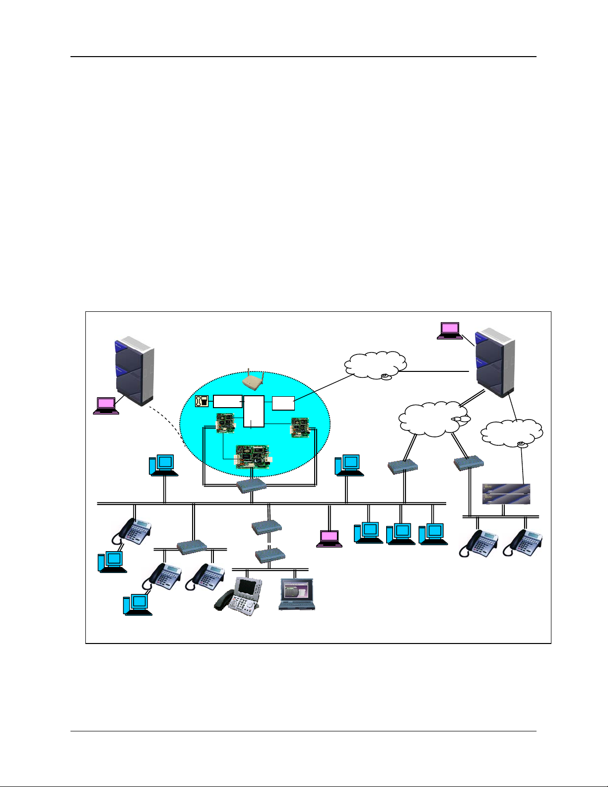
This manual provides an overview of the NEAX®2000 IPS (Internet Protocol Server) stored program
control digital electronic PBX. An introduction to the technical characteristics is included, along with
a description of available system applications.
System Information - NEA X®2000 IPS
The NEAX®2000 IPS (Internet Protocol Server) is a full-featured IP based communications system
providing a rich feature set with pure Voice over IP (VoIP) communications (peer to peer
connections), across corporate Local and Wide Area Networks (LAN and WAN). The NEAX 2000
IPS DtermIP telephones are designed to provide a converged infrastructure at the desktop, with a
100 Base T Ethernet connection to the LAN and built-in hub for a PC connection to the telephone
itself. The system can provide peer-to-peer connections between DtermIP telephones with voice
compression, offering existing Dterm Series i telephone features. On the WAN side, the system can
provide peer-to-peer connections over IP networks with the voice compression, on a CCIS basis
(CCIS over IP) or Remote PIM (Remote PIM over IP).
NEAX 2000 Internet Protocol Server (IPS)
NEAX 2000 IPS General Description Page 10
NDA-24345, Issue 3
Page 17
CHAPTER 1 INTRODUCTION
)
The NEAX 2000 IPS can provide legacy station/trunk interfaces to support the existing Time
Division Multiplexing (TDM) based infrastructure, such as analog telephones, analog networks, and
digital networks (T1/E1, ISDN etc.). At maximum configuration, the system can provide 1020 ports
for IP and legacy devices, and 256 ports for Application cards. Communications between legacy
stations/trunks and DtermIP telephones/IP networks are made via IP PAD, which converts packetbased voice data to TDM-based voice data, and vice versa. Both peer-to-peer connections and
TDM-based connections are controlled the Main Processor (MP) card. The MP card incorporates a
built-in Device Registration Server (DRS) and a single interface point of IP connection to IP
telephone, MATWorX, and OAI/ACD servers.
NEAX 2000 IPS users have access to hundreds of service features that ar e used in building unique
telephony applications that enhance productivity, reduce operating costs and improve
communications efficiently. The innovative modular hardware and software design allows efficient,
effective growth within each module from its minimum to its maximum configuration. The N EAX
2000 IPS software design is as advanced as its hardware. It ensures the system will support evolving
applications and have the reliability needed to compete in today's world and into tomorrow's. The
software is designed with modularity in mind. Together, these modular building blocks allow
customers to initially buy what they need and add cap acity and cap abilities as the bus iness demands,
resulting in a greater degree of cost control for new installations and for upgrades to features,
capacities and the software versions.
NEAX 2000 IPS
MATWorX
(via RS232C)
DtermIP
Client PC
DRS
Switching
Hub
DtermIP
LC/DLC
IP-PAD
MP
Switching Hub (100Mbps
COT
IPT(H.323
Handler)
Router
H.323 GK
MATWorX
(via LAN)
PSTN
Router
OAI
Server
Dterm
Assistant
MATWorX
(Via IPT:CCIS)
CCIS over IP
Internet
/Intranet
Router
DHCP
Server
NEAX 2000 IPS
PSTN
DM
NEAX IPS
DtermIP
Remote PIM over IP
with Survivability
Client PC
Dterm
INASET
Dterm SP30
Figure 1-1 System Outline of an IPS
NEAX 2000 IPS General Description Page 11
NDA-24345, Issue 3
Page 18

CHAPTER 1 INTRODUCTION
Hardware Architecture
Hybrid System of IP (peer-to-peer connection) and TDM Switching
The NEAX 2000 IPS supports both pure IP switching (peer-to-peer connections) and Time Division
Switching (TDM). The pure IP switching is provided for communications between DtermIPs and for
CCIS/Remote PIM connections with another NEAX 2000 IPS/ NEAX IPS
IP or Remote PIM over IP). On the other hand, the TDM switching is provided for communications
between legacy stations/trunks. Connections between DtermIP/CCIS or Remote PIM over IP and
legacy stations/trunks are made via IP PADs, which converts packet-based voice data to TDM-based
voice data, and vice versa.
Powerful, One-board Main Processor (MP) with Integrated Functionality
The NEAX 2000 IPS Main Processor (MP) is the heart of pure IP connections and TDM-based
connections. The MP employs a high-speed CPU, which is equivalent with Pentium. With this
processing power and System On Chip (SOC) technology, the MP integrates Device Registration
Server (DRS), AP01 (OAI) functions, which are provided by an additional card in the prev ious IVS
series. Also, by means of today’s advanced LSI technology, the MP card size is minimized and Onboard Ethernet Interface card is mounted on the MP without using an additional slot space in the
PIM. This interface card is linked with LAN for call control processing of DtermIP and inter-work
with MATWorX and OAI server.
The MP provides LAN control function, System-based Device Registration Server (DRS), Built-in
FP, Built-in OAI, Built-in SMDR, Built-in CCH-IPT, 33 MHz PCI BUS, Memory
(Basic/Expansion), TDSW (1024 CH × 1024 CH), 16-line CFT, PB Sender, Clock, PLO two ports
(Receiver Mode/Source Mode), two RS-232C Ports, two-line DAT (Recording duration: a maximum
of 128 seconds), DK, 4-line PB Receiver, Modem for remote maintenance (33.6 kbps), internal
Music-on-Hold Tone, BUS Interface. BUS Interface functions as a driver/receiver of various signals,
adjusts gate delay timing and cable delay timing, monitors I/O Bus and PCM BUS. One card is
required per system.
DM
/2400 IPX (CCIS over
Reduced Hardware with IP based Architecture
The DtermIPs connected to the LAN do not require DLC cards because they can be interfaced
directly with the LAN and connected with peer-to-peer basis. When the DtermIP is connected to a
station/trunk that is using TSW, the speech path between LAN and TSW is made via IP PAD under
the call processing control of the MP. The DtermIP can be expanded simply adding the terminal
itself and IP PAD if traffic volume is increased. With this system architecture, the hardware such as
DLC, PIM, Power Supply etc. is reduced and easy moves, adds, and changes can be realized.
Standard TDM Hardware Peer to Peer IP Hardware
Line & Trunk Cards
Application Processors
Firmware Processors
SPN-8IPLA IP PAD
PZ-M606-A
PN-24IPLA IP PAD*
* The PN-24IPLA is a daughter board for
the 8IPLA when up to 32 IP PADs for
desired.
NEAX 2000 IPS General Description Page 12
NDA-24345, Issue 3
Page 19

CHAPTER 1 INTRODUCTION
Enhanced Built-in Firmware Processor (FP) on MP
The Firmware Processor card (FP) provides Line/Trunk interface, Memory (RAM 768 KB), and
inter-module BUS interface. BUS interface functions as a driver/receiver of various signals, adjusts
gate delay timing and cable delay timing, and monitors I/O Bus and PCM BUS. When the system
consists of three PIMs or more, one each of this card is mounted respectively in PIM 2, PIM 4, and
PIM 6.
Extended Application Processor (AP) Port Capacity
The NEAX 2000 IPS provides maximum 256 AP ports and it is independent of the 512 ports for the
Line/Trunk (LT), therefore, more AP cards such as T1/E1 digital link cards can be used in the
system.
Universal Slot
One PIM provides 12 card slots for Line/Trunk (LT). Also, these card slots can be used for
Application Processor (AP) cards without complicated limitation. This makes easy quotation and
installation, and more AP cards can be mounted in one PIM.
Unified Circuit Card Size
All circuit cards for the NEAX 2000 IPS are designed in one size (PN-type), and installed in the
PIM. This maximizes the efficiency of slot utilization of the PIM.
High Density Line/Trunk Cards
The major line/trunk cards used in the NEAX 2000 IPS are provided with 8 circuits per card. This
allows the physical system size to be compact.
DC/DC Power Supply for –48V
The PIM houses optional DC/DC Power Supply for the cards which require –48V power such as the
CSI card used for interface of Zone Transceiver of wireless system. Since this power supply is
mounted in the space under the AC/DC power, no additional Power Module/card slots are required.
Built-in DRS (Device Registration Server) on MP
The NEAX 2000 IPS incorporates DRS (Device Registration Server) on the MP. DRS provide Login/Log-out management of DtermIP including Registration and Authentication. Also, the built-in
DRS can be inter-worked with DHCP server to provide easy administration on IP address.
Office Data Backup Enhancement
The office data of the NEAX 2000 IPS is stored in Flash ROM; therefore the backup period is
extended compared with previous IVS series which were using RAM with battery.
Various Installation Methods
To meet the specific needs of the customer’s environment, the NEAX 2000 IPS provides the
following installation methods:
Floor Standing Installation
Wall-mounting Installation
IEC standard 19 inch Rack-mounting Installation
NEAX 2000 IPS General Description Page 13
NDA-24345, Issue 3
Page 20

CHAPTER 1 INTRODUCTION
Station to Station Connection
For DtermIP to DtermIP connection (Peer to Peer connection), the voice data is transmitted and
received directly between DtermIPs on the LAN. For Dterm Legacy terminal connection, the IPPAD card and VCT card are required to transmit and receive the voice data. These c ards are used to
control and convert the voice data. The MP card in either of the connections above manages the
control signals.
CCIS Connection
DtermIP to DtermIP connection (Peer to Peer connection) via CCIS is available only when the
destination office is NEAX 2000 IPS or NEAX 2400 IPX. The system provides only Point to
Multipoint connection.
Maintenance
MATWorX IPS is used as the maintenance program for the NEAX 2000 IPS. Direct connection
(RS-232C), Modem connection and LAN (TCP/IP) connections are available to connect to the MAT
(Maintenance Administration Terminal).
Dual MP System
The system complies with dual control system on Main Processor.
Note: Since the system employs Cold Standby processing in MP changeover, the calls in progress
are terminated as a result of the MP changeover. Also, during the MP changeover, the call
originating/receiving and service feature access are not effective. (It takes about 30 to 60 seconds to
complete the MP changeover.)
Remote PIM over IP with Survivability
The NEAX 2000 IPS can have a PIM installed at a remote site through an IP network. At the main
site, the NEAX 2000 IPS/NEAX IPS
DMR
IPS
are installed at the remote site. The main site controls call processing and servi ce feature
DM
is installed and NEAX 2000 IPS/NEAX IPSDM/ NEAX
access for station users located at both the main and remote sites. When the Remote PIM cannot be
connected with main site due to the IP network and/or main PBX failure, the Remote PIM initializes
the system and re-starts operation by its own Main Processor (survival mode). In the survival mode,
almost all service features are provided to the station users accommodated in Remote PIM. When
the IP network/main PBX recovers, the Remote PIM can be restored to normal mode with a system
initialization by manual operation or automatically (Selectable by system data setting).
• IPS
• IPS
DM
with CP24-A MP
DMR
with CP31-A MP
NEAX 2000 IPS General Description Page 14
NDA-24345, Issue 3
Page 21

Software Architecture
Generic Program
Description Remarks
CHAPTER 1 INTRODUCTION
64 Port Sys Software (FD)
Note: The MP (PN-CP24) comes with 48 Ports of basic software, which supports up to 48 LT Ports & 1 T1.
Description Remarks
Key Keeper (FD) Floppy Disk that holds selected Key Files for Capacity Options
LT 64 Ports
CCIS Link (1) Adds support for one CCIS Link
CCIS Link (4) Adds support for four CCIS Links
CCIS Link (8) Adds support for eight CCIS Links
IPT Card (1) Adds support for PTP CCIS or one IP Trunk Card
IPT Card (4) Adds support for up to four IP Trunk Cards
IPT Card (8) Adds support for up to eight IP Trunk Cards
ECCIS Adds Event Based CCIS capability (used w/CCIS keys)
Wireless Adds Wireless Capability Supports 128 ZT’s & 256 PS’s
Wireless – 8 PS License Adds additional licenses (increments of 8) for over 256 PSs
T1/E1 6 to 10 Cards Expands T1/E1 Capacity between 144 to 240 Channels.
ISDN DCH 5 to 8 Cards
R-PIM 1 Site License
IPT Card (1) Adds support for PTP CCIS or one IP Trunk Card
8 Seat License
Soft-Phone 4 Seat License
SP30 - 4 Seat License
Basic Business/Hotel/Motel Features for: 64 LT Ports, 5 T1’s /E1’s,
5 ISDN-PRI DCH’s, 48 ISDN-BRI Trunks.
Capacity options (used w/Key Keeper)
64 Port Line/Trunk Key (incremental)
Software and provides LT Port Licenses in 64 port increments
from 64 to1020 ports. Stand alone system maximum 512 LT ports,
Remote PIM Network maximum 1020 LT ports.
Expands ISDN PRI Capacity between 5 DCH Cards and 8 DCH
Cards.
Site License for DMR/IP Remote PIM.
One License required per Remote Site.
Required for eight or less Dterm IP Terminals and IP Soft-Phones.
Incremental eight Seat License for Peer to Peer IP
Note: IP Seat Licenses are Accumulative. (i.e. 24 IP = three 8 Seat
License)
4 seats Dterm SP20 licenses - Requires an available 8 SEAT
LICENSE seat per Soft-phone seat activated.
Note: Soft-Phone 4 Seat Licenses are used in addition with 8 Seat
License when using the SP20 SoftPhone
4 seat Dterm SP30 license.
Incremental one seat used for each Soft-Phone client.
Note: Soft-Phone 4 Seat Licenses are used in addition with 8 Seat
License when using the SP20 SoftPhone
NEAX 2000 IPS General Description Page 15
NDA-24345, Issue 3
Page 22

CHAPTER 1 INTRODUCTION
Technical Terms
SYMBOL DESCRIPTION SYMBOL DESCRIPTION
AP00
SMDR/Hotel Application Card
LC
AP01 OAI Interface Card LDT LD Trunk Card
AUC
BGM
BRT
Analog Universal Circuit Card
(Long Line Circuit, DID Trunk)
External Music Source for D
term
Back Ground Music Service
Basic Rate Interface Trunk Card
M03
M10
MAT
CCH Common Channel Handler Card MDF Main Distribution Frame
CFT 6/10 Party Conference Trunk Card MEM Main Memory
CIS
Call Information System
MFR
CIR CALLER ID Receiver Trunk Card MLDT Melody Trunk
COT C.O. Trunk Card MODEM Modem
CSI CS/ZT Interface Card MP Main Processor Card
Cell Station (For Australia/Others)
CS/ZT
Zone Transceiver (For North
PFT
America/ Latin America)
DAT Digital Announcement Trunk Card PMS Property Management System
DCH D-channel Handler Card OAI Open Application Interface
DIT
DID Trunk Card
ODT
DK External Relay/Key Interface Card PBR PB Receiver Card
DLC
Digital Line Circuit Card
term
(for D
, ATTCON, DESKCON)
PBSND
DPC Data Port Controller Card PLO Phase Locked Oscillator
DSS DSS Console PS Personal Station
DTE
DTI
Data Terminal Equipment
Digital Trunk Interface Card
PRT
SMDR
DTG Digital Tone Generator TDSW Time Division Switch
ETHER
Ethernet Control Card
TNT
EXPMEM Memory Expansion Card VCT CODEC Card
ICH ISDN-channel Handler Card VM Voice Mail Card
ILC
ISDN Line Circuit Card
16CFT
IPT IP Trunk Card KEY External Key
Line Circuit Card
(for Single Line Telephone)
V.35 DTE Interface Card
Optical Interface Card
Maintenance Administration
Terminal
MF Receiver/ MFC
Receiver/Sender Card
Power Failure Transfer
OD Trunk Card (2/4 wire
E&M)
PB Sender
ISDN Primary Rate Interface
Trunk Card
Station Message Detail
Recording
Tone/Music Source Interface
Card
16 Circuit Four Party
Conference Trunk
NEAX 2000 IPS General Description Page 16
NDA-24345, Issue 3
Page 23
CHAPTER 1 INTRODUCTION
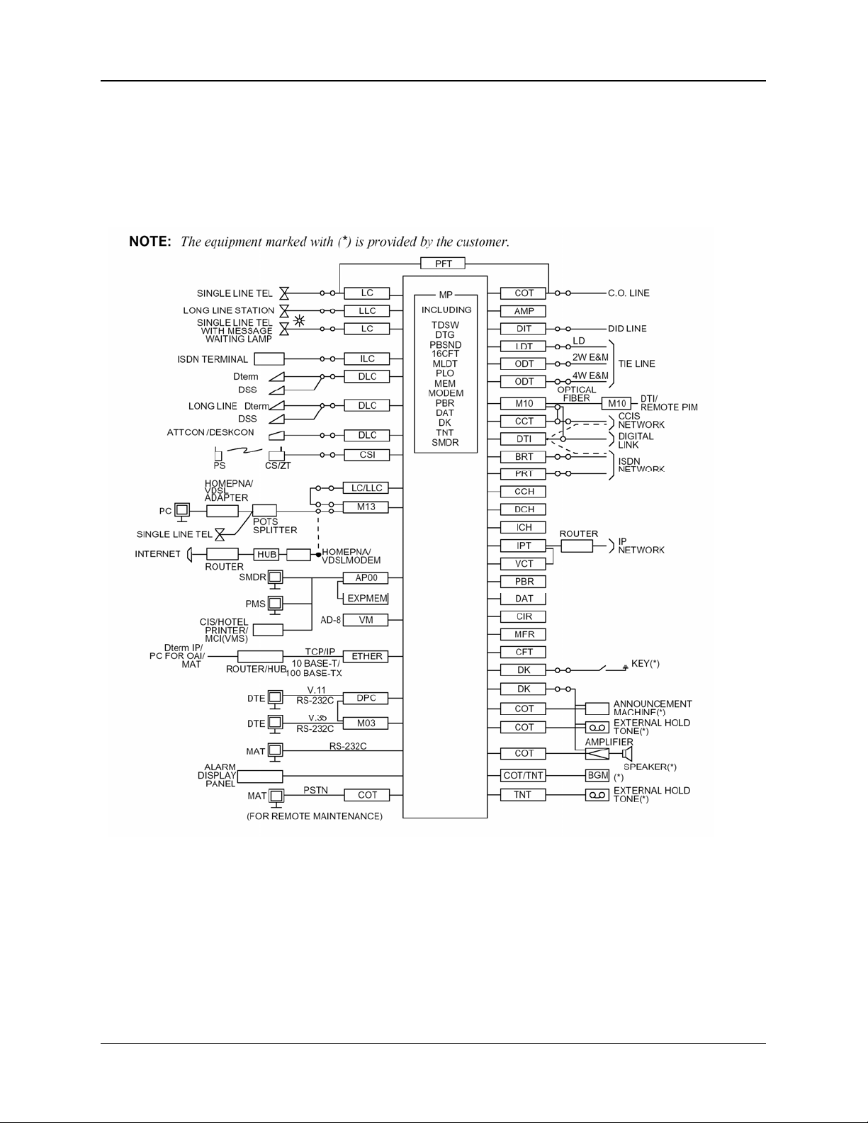
Trunking Diagram
This figure shows a typical trunking diagram of the NEAX2000 IPS system.
NEAX 2000 IPS General Description Page 17
NDA-24345, Issue 3
Page 24

CHAPTER 1 INTRODUCTION
NEAX® 2000 IPSDM
The NEAX IPSDM (Internet Protocol Server Distributed Model) is equipped with all the features and
functions of the NEAX 2000 IPS, with a smaller space requirement. It is a full-featured PBX that
supports advanced networking, pure peer-to-peer IP telephony connectivity and traditional TDM
switching capabilities. Designed primarily for pure converged IP networks, the NEAX IPS
also accommodate a mixed (i.e., TDM and IP) converged IP network or standalone solution.
The NEAX IPS
DM
supports up to 956 peer-to-peer IP stations and 40 TDM ports in a single modular
chassis. Up to three chassis can be stacked providing maximum capacity of 120 legacy TDM ports
while still supporting as many as 828 peer-to-peer IP stations or more depending on the amount of
TDM stations used. It uses the same CPU, line/tr unk cards, application processor cards and software
of the NEAX 2000 IPS and comes equipped for 19” rack mounting. It offers superior port density;
each chassis only occupies two Rack Units (2RU).
Characteristics of the NEAX IPS
DM
Compact and Small Size MODULAR CHASSIS
One MODULAR CHASSIS provides 6 card slots /40LT ports and up to 3 MODULAR CHASSIS
can be used per system. (24 virtual LT ports are available per MODULAR CHASSIS in addition to
40LT ports.)
2 types of MP (Main Processor)
MP can be selected from the following options by customer requirements.
• PN-CP24-A for IPS
• PN-CP31-A for IPS
DM
, the same MP as the NEAX 2000 IPS.
DMR
, the following functions are removed from the CP31: DAT / DK00 /
1 RS232C Port for MAT / MN Alarm Indication
Power Failure Transfer (PFT)
Power Failure Transfer (PFT) for the IPS
the NEAX 2000 IPS is not available for the IPS
DM
is provided with PZ-4PFTA card. The PZ-8PFTB for
DM
.
DM
IPS
Installation Methods
Wall Mount Installation is not available. The NEAX IPS
DM
can be installed on the desktop or into
the 19-inch rack.
DM
can
NEAX 2000 IPS General Description Page 18
NDA-24345, Issue 3
Page 25

CHAPTER 1 INTRODUCTION
NEAX® 2000 IPS
The NEAX IPS
been optimized for Remote PIM over IP applications. The NEAX IPS
DMR
DMR
(Internet Protocol Server Distributed Model Remote) is a NEAX IPSDM that has
DMR
uses the SPN-CP31 as the
Main Processor. The SPN-CP31 is a cost down CPU to compete with Mitel 3100, NBX25, and
CISCO 2600 Series. This system targets users who have up to 15 relatively small offices that
accommodate 10-30 extensions at the Remote Site.
The MP card at Remote Site has the same system data as that at Main Site, because Remote Site
automatically gets the data from Main Site at the time of setup. In normal operation, Main Site
automatically copies the system data to Remote Site through the network once a day.
Because the CP31 is a cost down CPU, the following options that are built-in on the CP24 are not
available with the CP31:
• No built-in modem.
• No built-in DAT.
• Only one RS Port.
• No built-in DK (external/relay key).
• No MN Alarm Indication
System Outline
• The MP card at Main Site controls system processing, and Remote Site follows the Main
Site.
• Remote Site can accommodate most terminals and trunks such as Dterm, Single-Line
telephone, PS, DtermIP, COT, ISDN, etc. The Attendant Console, Dterm Attendant position ,
Add-on Module and DSS/BLF are not supported at the Remote Site.
• Local Switch (TDSW) at Remote Site controls connections within the Remote Site if
possible.
• In the case of connections between Main-Remote and Remote-Remote, the voice path is
connected via Peer-to-Peer or IP-PAD.
• If the communications between Main-Remote are interrupted, the Remote Site survives by
itself after the system reset.
Advantages
• The system regards the terminals accommod ated in both Main Site and Remote Site as the
extensions in the same office. Therefore, the service transparency is superior to CCIS.
• Remote PIM over IP has no limitation of distance between Main and Remote.
• Remote Site has a switching function at local. This provides the effective configuration of
C.O. line. In addition, the Remote Site can accommodate AP cards. This is an advantage to
accommodate ISDN lines especially.
• The Remote Site survives by itself even if the link between Main and Remote is
disconnected. Therefore, the impact to users at Remote Site will be smaller if the link
between Main and Remote is disconnected.
• This feature can reduce the bandwidth used on the WAN that is connected to CO lines at
Remote Site, rather than DtermIP at remote location or the Media Converter (MC)
accommodation.
NEAX 2000 IPS General Description Page 19
NDA-24345, Issue 3
Page 26

CHAPTER 1 INTRODUCTION
Remote PIM over IP
Remote PIM over IP targets users who have 1-15 relatively small offices that accommodate 10-30
extensions at the Remote Site. When IPS
connected to a 2000 IPS or IPS
DM
at main site over IP network, the Main Site system controls and
DMR
and 2000 IPS PIM are installed at remote site, and
maintains the remote DM and PIM operation as one single system. If a communication failure occurs
between the Main Site and Remote Site, the Remote Site automatically changes over to a survival
mode and operates as a stand-alone system.
DMR
IPS
IPS
: IPS Distributed Model Remote (with CP31-A)
DM
: IPS Distributed Model (with CP24-A/B)
The NEAX IPS-DMR is designed primarily for distributed IP networking but also supports
traditional analog and digital trunks for connection to the Public Switched Telephone Network
(PSTN). The NEAX IPS-DMR supports up to 128 peer-to-peer IP stations and 40 TDM ports in a
single modular chassis. Up to two chassis can be stacked providing maximum capacity of 80 TDM
ports while still supporting as many as 128 peer-to-peer IP stations.
Note: The MP card at Remote Site has the same system data as the CPU at the Host Site; the Host Site
automatically downloads system data to the Remote Site at the time of setup. In normal operation, Main Site
automatically downloads a copy the system data to Remote Site through the network once a day.
Because the CP31 is designed as a Remote PIM CPU, the following options that are bui lt-in on the
CP24 are not available with the CP31:
• No built-in modem.
• No built-in DAT.
• Only one RS Port.
• No built-in DK (external/relay key).
• No MN Alarm Indication
Network Conditions and Payload
Item Requirement Remarks
Protocol TCP/IP transparent
Maximum
Delay Time
120ms(one way)/240ms(return)
150ms(one way)/300ms(return)
Support the quality class A,
B of IP Telephone
NEAX 2000 IPS General Description Page 20
NDA-24345, Issue 3
Page 27

CHAPTER 1 INTRODUCTION
Bandwidth Requirement
Established
Voice Calls
Control 4.1 Kbps 4.1 Kbps 4.1 Kbps
6
Voice 31.8/37.8 Kbps 48 Kbps 432 Kbps
Control 4.3 Kbps 4.3 Kbps 4.3 Kbps
8
Voice 42.4/50.4 Kbps 64 Kbps 576 Kbps
Control 4.3 Kbps 4.3 Kbps 4.3 Kbps
12
Voice 63.6/75.6 Kbps 96 Kbps 864 Kbps
Control 4.5 Kbps 4.5 Kbps 4.5 Kbps
16
Voice 84.8/100.8 Kbps 128 Kbps 1152 Kbps
Control 4.5 Kbps 4.5 Kbps 4.5 Kbps
24
Voice 127.2/151.2 Kbps 192 Kbps 1728 Kbps
Control 4.9 Kbps 4.9 Kbps 4.9 Kbps
32
Voice 169.6/201.6 Kbps 256 Kbps 2304 Kbps
Control 4.9 Kbps 4.9 Kbps 4.9 Kbps
48
Voice 254.4/302.4 Kbps 384 Kbps 3456 Kbps
Control 5.8 Kbps 5.8 Kbps 5.8 Kbps
64
Voice 339.2/403.2 Kbps 512 Kbps 4608 Kbps
Control 5.8 Kbps 5.8 Kbps 5.8Kbps
72
Voice 381.6/453.6 Kbps 576 Kbps 5184 Kbps
Control 6.7 Kbps 6.7 Kbps 6.7 Kbps
96
Voice 508.8/604.8 Kbps 768 Kbps 6912 Kbps
With G7.23.1
(5.3k/6.3k)
Compression
With G729a ( 8k)
Compression
Without
Compression
(G.711)
Note: This information is an estimation based on an established call. Slightly Higher Control values will
occur at time of call origination and termination.
Base values
• Originating from a station: 9.6 Kbps/Call (estimated)
• Terminating to a station: 5.76 Kbps /Call (estimated)
• Originating to C.O: 11.5 Kbps/Call (estimated)
• Terminating from C.O: 5.76 Kbps/Call (estimated)
• Keep Alive to Remote Site: 0.032Kbps (estimated)
• Other control packets for Remote Site: 4Kbps (estimated)
• G.723.1 voice: 5.3Kbps (one-way)
• G.729a voice: 8Kbps (one-way)
• G.711 voice: 64Kbps (one-way)
The above base values are primarily used for call setup with the exception of keep alive; 0.032Kbps
with no voice traffic. Connections between IP PAD are half duplex, established call utilization is
G.711 voice: 64Kbps, G.723.1 voice: 5.3/6.3Kbps, or G729a voice: 8Kbps. Peer-to-Peer IP station
calls are full duplex, compression can be specified by location numbers in system data. Peer-to Peer
IP station calls even though full duplex will utilize one-way for Bi-directional networks such as T 1.
Peer-to Peer IP station calls over Asymmetrical networks such as ADSL may realize higher
bandwidth utilization, compression can be specified by location numbers in system data.
NEAX 2000 IPS General Description Page 21
NDA-24345, Issue 3
Page 28

CHAPTER 1 INTRODUCTION
Advantages
The system regards the terminals accommodated in both Host Site and Remote Site as the extensions
in the same office. Feature transparency is superior to CCIS.
The Digital Remote PIM cannot accommodate AP cards; Remote PIM over IP can accommodate AP
cards such as ISDN PRI and T1.
This feature can reduce the bandwidth used on the WAN that is connected to CO lines at Remote
Site, rather than Dterm
IP at remote locations.
Since all Remote PIM over IP sites are treated as extensions in the same office, software and
applications only have to be implemented in the host site. This provides centralized use of
application for example distributing ACD agents in the DMR locations. CCIS requires each location
to have separate software and applications.
CCIS over IP can be combined with Remote PIM over IP to accommodate larger network
configurations. Up to 255 host sites can be connected via CCIS, each host site can have up to 15
Remote PIM over IP locations.
Service Conditions
1. Host site can be NEAX 2000 IPS, NEAX IPS DM, or NEAX 2000 Retrofit system. Remote
PIM over IP is available in any combination of the following CPUs.
Main Site: CP24-A/B, CP27-A, CP26-A, CP28-A
Remote Site: CP31-A, CP24-A/B, CP27-A, CP26-A, CP28-A
2. Software and Key FD for the whole system must be loaded at the Host Site. No software or
key’s can be loaded into the Remote Site.
3. All system data changes f or the whole system must be performed in the Host Site. No system
data changes can be done in the Remote Site.
4. The CPU card at Re mote Site has the same system data as the CPU at Main Site; the Host
Site automatically downloads its system data to the Remote Site at the time of setup. In
normal operation, Host Site automatically copies the system data to Remote Site through the
network once a day.
5. Remote Site automatically operates by itself (survival mode) when Keep Alive signal (sent
every 30 sec) between the Host Site and Remote Sits is interrupted. When Keep Alive is
interrupted the Remote Site is reset to change the operation from normal mode to survival
mode.
6. Remote Site in survival mode checks at 30 seconds intervals if the co mmunications to Main
Site are possible. When Keep Alive is detected, the Remote Site automatically is reset to
change the operation from survival mode to normal mode.
7. When unstable conditions occur in the network, the Remote Site can be manually set to
survivable mode (override automatic) until stability in the network is established. This
prevents the Remote Site from resetting normal mode to survivable mode etc.
NEAX 2000 IPS General Description Page 22
NDA-24345, Issue 3
Page 29
Required Hardware and Software
Host Site
Equipment Name Remarks
PZ-M606-A On board Ethernet Interface card
SPN-8IPLA IP PAD 8 Port PAD with built-in compression
PZ-24IPLA 24 Port PAD Expansion, mounts on SPN-8IPLA
R-PIM 1 Site License 1 required for each Remote site
Note: Registration of Host CPU and software required
DMR Site
Equipment Name Remarks
PZ-M606-A On board Ethernet Interface card
SPN-8IPLA IP PAD 8 Port PAD with built-in compression
PZ-24IPLA 24 Port PAD Expansion, mounts on SPN-8IPLA
Note: Registration “not” required
CHAPTER 1 INTRODUCTION
NEAX 2000 IPS General Description Page 23
NDA-24345, Issue 3
Page 30

t
t
Chapter 2 System Configuration
Module Configuration
The NEAX® 2000 IPS consists of single or multiple Port Interface Modules (PIM) depending on the
system configuration, and there are two types of PIMs; “Physical” PIM and “Virtual” PIM. The
Physical PIM is “hardware” PIM which is used to accommodate an MP, FPs, IP PADs, legacy LT
cards, AP cards, and power supply units. One Physical PIM provides up to 64 LT ports and up to 8
Physical PIMs can be accommodated in a Stand Alone system. The Virtual PIM is a “software” PIM
and provides up to 64 ports per PIM for use by system programming as DtermIP telephones,
Wireless PS stations or Peer to Peer (PTP) CCIS trunks. The system consists of up to 16 PIMs, by
the combination of Physical PIMs and Virtual PIMs, thus providing 1020 ports. When the use of
Virtual PIMs exceeds 8 then the number Physical PIMs is reduced by one for each additional Virtual
PIM required.
The illustration below shows examples of 1020-port configuration by the combination of TDM LT
ports, Dterm IP telephones, Wireless PS stations and Peer to Peer (PTP) CCIS trunks.
Figure 2-1 System Configuration with Dterm IP (1020-Port Configuration)
Example 1 Example 2
PIM #3
PIM #2
PIM #1 PIM #5
PIM #0 PIM #4
448 LT ports +
64 IP-PADs
PIM #7
PIM #6
PIM #11
PIM #10
PIM #9 PIM #13
PIM #8 PIM #12
252 D
128 Wireless +
128 PTP CCIS
PIM #15
PIM #14
erm
IPs +
PIM
Physical PIM
PIM #3
PIM #2
PIM #1 PIM #5
PIM #0 PIM #4
192 LT ports +
64 IP-PADs
PIM #7
PIM #6
PIM
Virtual PIM
PIM #11
PIM #10
PIM #9 PIM #13
PIM #8 PIM #12
508 D
128 Wireless +
128 PTP CCIS
PIM #15
PIM #14
erm
IPs +
NEAX 2000 IPS General Description Page 24
NDA-24345, Issue 3
Page 31

CHAPTER 2 SYSTEM CONFIGURATION
The figure 2-2 shows another example of 1020-port configuration by combination of legacy LT ports
and Dterm IP telephones.
PIM #3 PIM #7
PIM #2 PIM #6
PIM #1 PIM #5
PIM #0 PIM #4
PIM #3 PIM #7
PIM #2 PIM #6
PIM #1 PIM #5
PIM #0 PIM #4
PIM #3 PIM #7
PIM #2 PIM #6
PIM #1 PIM #5
PIM #0 PIM #4
PIM #3 PIM #7
PIM #2 PIM #6
PIM #1 PIM #5
PIM #0 PIM #4
64 LT ports
+ 952 D
term
IPs
128 LT ports
+ 888 D
term
IPs
192 LT ports
+ 824 D
term
IPs
256 LT ports
+760 D
term
IPs
PIM #3 PIM #7
PIM #2 PIM #6
PIM #1 PIM #5
PIM #0 PIM #4
PIM #3 PIM #7
PIM #2 PIM #6
PIM #1 PIM #5
PIM #0 PIM #4
PIM #3 PIM #7
PIM #2 PIM #6
PIM #1 PIM #5
PIM #0 PIM #4
PIM #3 PIM #7
PIM #2 PIM #6
PIM #1 PIM #5
PIM #0 PIM #4
320 LT ports
+ 696 D
term
IPs
384 LT ports
+ 632 D
term
IPs
448 LT ports
+ 568 D
term
IPs
512 LT ports
+ 504 D
term
IPs
PIM PIM
Physical PIM
Virtual PIM
Figure 2-2 System Configuration with Dterm IP (1020-Port Configuration)
NEAX 2000 IPS General Description Page 25
NDA-24345, Issue 3
Page 32

CHAPTER 2 SYSTEM CONFIGURATION
Installation Methods
The NEAX2000 IPS provides three installation methods as follows:
Floor Standing Installation
Wall Mounting Installation
19-inch Rack Mounting Installation
Floor Standing Installation
In Floor Standing Installation, the NEAX 2000 IPS is comprised of up to 8 Port Interface Modules
(PIMs).
PIM #0
BASE
(64 ports)
PIM #3
PIM #2
PIM #1
PIM #0 PIM #4
BASE BASE
(320 ports)
PIM #1
PIM #0
BASE
(128 ports)
PIM #3
PIM #2
PIM #1 PIM #5
PIM #0 PIM #4
BASE BASE
(384 ports)
PIM #2
PIM #1
PIM #0
BASE
(192 ports)
PIM #3
PIM #2 PIM #6
PIM #1 PIM #5
PIM #0 PIM #4
BASE BASE
(448 ports)
PIM #3
PIM #2
PIM #1
PIM #0
BASE
(256 ports)
PIM #3 PIM #7
PIM #2 PIM #6
PIM #1 PIM #5
PIM #0 PIM #4
BASE BASE
(512 ports)
Figure 2-2 System Configuration in Floor-standing Installation
NEAX 2000 IPS General Description Page 26
NDA-24345, Issue 3
Page 33

CHAPTER 2 SYSTEM CONFIGURATION
Wall-mounting Installation
The NEAX 2000 IPS can be wall-mounted with single or multiple PIM configurations (maximum of
eight PIMs).
Figure 2-3 Wall-mounting Installation
NEAX 2000 IPS General Description Page 27
NDA-24345, Issue 3
Page 34

CHAPTER 2 SYSTEM CONFIGURATION
19 inch Rack-mounting Installation
The NEAX 2000 IPS can be mounted in the IEC-standard 19 inch rack up to four PIMs.
(IEC: International Electro-technical Commission)
Figure 2-4 19-inch Rack-mounting Installation
NEAX 2000 IPS General Description Page 28
NDA-24345, Issue 3
Page 35

CHAPTER 2 SYSTEM CONFIGURATION
Modules and Installation Hardware
The NEAX 2000 IPS is comprised of up to 8 Port Interface Modules (PIMs).
Modules
(1) Port Interface Module (PIM)
A PIM provides 13 card slots for common control, Line/Trunk (LT), and Application Processor (AP)
cards. It also houses an AC/DC Power Supply, DC/DC Power Supply (for -48V), and batteries for
protection from short-term (about 30 min.) power interruption. Four champ connectors for
Line/Trunk (LTC 0 to 3) are located at the lower front side of the PIM. A PIM provides a maximum
of 12 card slots for Line/Trunk (LT) and Application Processor (AP) cards. At maximum
configuration, the system is comprised of 8 PIMs.
There are two types of PIM (PIMMD and PIMMF) depending on the system type as follows.
Type of PIM Single MP System Dual MP System
PIM MD Used for PIM 0-7 Used for PIM 1-7
PIM MF Not used Used for PIM 0
PIM MD
(PIM3)
PIM MD
(PIM2)
PIM MD
(PIM1)
PIM MD
(PIM0)
(Single MP System)
(2) Battery Module (BATTM)
The BATTM is an optional module for installing optional long-term (about 3 hours) backup
batteries. The BATTM is designed to accommodate batteries covering up to a 4-PIM system (2
BATTMs support maximum system configuration). The BATTM is available for Floor Standing
Installation. (When the system is Wall-mounting/19 inch Rack-mounting configuration, the BATTM
cannot be installed with the PIM.)
Modules
PIM MD
(PIM7)
PIM MD
(PIM6)
PIM MD
(PIM5)
PIM MD
(PIM4)
Unit Configuration
PIM MD
(PIM3)
PIM MD
(PIM2)
PIM MD
(PIM1)
PIM MF
(PIM0)
(Dual MP System)
PIM MD
PIM MD
PIM MD
PIM MD
(PIM7)
(PIM6)
(PIM5)
(PIM4)
Abbrev Description Remarks
PIMMD SN1617 PIMMD
PIMMF SN1658 PIMMF
BATTM SN1619 BATTMB 1 per STACK, Max.2 per system
Single MP System: PIM 0 - PIM 7
Dual MP System: PIM 1 – PIM 7
Single MP System: Not used
Dual MP System: PIM 0
NEAX 2000 IPS General Description Page 29
NDA-24345, Issue 2
Page 36

CHAPTER 2 SYSTEM CONFIGURATION
Installation Hardware
Base/Top Assembly
The Base/Top Assembly includes a Base Unit and a Top Cover for the PIM. One Base/Top
Assembly is required for each PIM stack. The Base Unit also serves as the AC power distribution
panel for up to a four PIM configuration.
Hanger Assembly
The Hanger Assembly is used for Wall-mounting Installation. One set of Hanger Assembly is
required for each PIM.
19 inch Bracket
The 19-inch Bracket is a set of hardware used for 19-inch Rack-mounting Installation. The 19-INCH
RACK BRACKET (A) is installed on both sides of the PIM. One set of 19 inch Bracket (A) is
required for each PIM. The 19-INCH RACK BRACKET (B) is installed at the BASE of stack. One
19-INCH BRACKET (B) is required for each stack.
If the system is 2 PIM or more configurations with 19-INCH BRACKET (B), one set of 19-INCH
BRACKET (A) is also required for the topmost PIM.
Optional Brackets
The Mounting Bracket is used for Floor Standing Installation. Without Mounting Bracket, 1.1G
shockproof is provided for 1 to 3-module stack and 0.5G shockproof is provided for 4 or more
module stack. To enhance the shockproof capability to 1.1G, one set of Mounting Bracket is required
for each 4 or more module stack and attached to the topmost PIM.
The I/F Bracket is used for Floor Standing Installation to joint the neighboring topmost PIM in 6
PIM or more configurations. One set of I/F Bracket is required for multiple stacks.
The Base Tray Assembly is used for Floor Standing Installation for stationary equipment (UL
complied). One set of Base Tray Assembly is required for each stack.
Installation Hardware
Abbrev Description Quantity
Top Cover TOP COVER ASSEM
Base/Top ASSEM SN1545 BASERE 1/STACK
Hanger Assem HANGER ASSEM (UL) 1/PIM (Wall-mounting Installation)
19 INCH RACK BRACKET (A)
19 inch Bracket
19 INCH RACK BRACKET (B)
Mounting Bracket MOUNTING BRACKET OPTION (1/STACK)
I/F Bracket I/F BRACKET ASSEM OPTION (1/SYSTEM)
Base Tray BASE TRAY ASSEM OPTION (1/STACK)
1/STACK (BASE ASSEM is local
supply)
1/PIM (19 inch Rack-mounting
Installation)
1/STACK (19 inch Rack-mounting
Installation)
Page 30 NEAX 2000 IPS General Description
NDA-24345, Issue 3
Page 37

CHAPTER 2 SYSTEM CONFIGURATION
NEAX 2000 IPS SYSTEM POWER SUPPLY
AC/DC Power Supply
The AC/DC Power Card is mounted in the left side of each PIM. The AC/DC Power card provides
power to all circuit cards, which reside in the PIM. AC power requirements are as follows:
Input Voltage: 90 to 132 Vrms or 180 to 264 Vrms (selectable by switch) 50/60 Hz
DC/DC Power Unit
The DC/DC Power Unit is mounted under the AC/DC Power Card and generates -48 V power for the
circuit cards that need such power.
Battery Backup
Internal Short-term option
For customers requiring battery backup, short-term and/or long-term options are available. Two
3.4AH batteries are required per PIM, and installed inside of each PIM. Backup time is approx. 30
minutes when PHS (Wireless PS) is not accommodated and approx. 10 minutes when PHS (Wireless
PS) is accommodated in the system.
External Long-term option
Two 24AH batteries are required per each 2 PIMs, and installed inside of Battery Module in a stack
basis. Backup time is approx. 3 hours when PHS (Wireless PS) is not accommodated and approx. 2
hours when PHS (Wireless PS) is accommodated in the system. The batteries are varied depending
on the requested backup time. The battery shall be locally provided.
NEAX 2000 IPS General Description Page 31
NDA-24345, Issue 3
Page 38

CHAPTER 2 SYSTEM CONFIGURATION
Circuit Cards
The circuit cards used for NEAX 2000 IPS are divided into the following three types. According to
these card types, the mounting locations of card and port allocation of the Time Division Switch are
varied.
• Common Control Cards
- Main Processor (MP)
- Firmware Processor (FP)
- Ethernet
- Power
• Line/Trunk (LT) Cards
- IP PAD, Line Circuit (LC), Central Office Trunk (COT), Tie Line Trunk (LDT/ODT), etc.
• Application Processor (AP) Cards
- SMDR/PMS/CIS/Hotel Printer Interface (AP00)
- T1/E1 Digital Trunk Interface (DTI)
Page 32 NEAX 2000 IPS General Description
NDA-24345, Issue 3
Page 39

CHAPTER 2 SYSTEM CONFIGURATION
IPS System Conditions
2000 IPS is an IP communication system that integrates voice terminals through Peer-to-Peer
connection to the IP network. The system is a hybrid system to accommodate both IP multiline
terminals (DtermIP) and the Legacy PBX’s terminals (Legacy terminal). Line/Trunk cards and
Application Processor cards can be mounted in the system to provide the Legacy PBX features that
use the Time Division Switch (TDSW).
Station-To-Station Connection
Station-to-Station connection is available on the LAN. For DtermIP-to-DtermIP connection
(Peer-to-Peer connection), the voice data is transmitted and received directly between
DtermIPs on the LAN. For DtermIP-to-Legacy terminal connection, the IP-PAD card is
required to transmit and receive the voice data. This card is used to control and convert the
voice data. The MP card manages control signals in both types of connections.
Public Network/TIE Network Connection
The system can be connected with a Public Network or Tie Line Network. When the
DtermIP communicates with the DtermIP/Legacy terminal in the destination office via Public
Network or Tie Line Network, the IP-PAD card and the trunk card are required to transmit
and receive the voice data.
CCIS Connection
The system can be connected with the IP network by No. 7 Common Channel Inter-office
Signaling (CCIS) via the Virtual IPT, when the destination office is 2000 IPS or 2400 IPX.
For DtermIP-to-DtermIP connection via CCIS (Peer-to-Peer connection), the voice data is
transmitted and received directly between DtermIPs vi a the IP network (CCIS via IP). For
DtermIP-to-Legacy terminal connection via CCIS, the IP-PAD card is required to trans mit
and receive the voice data. This card is used to control and co nvert the voice data. T he MP
card has a built-in Virtual IPT and the Virtual IPT manages control signals in both types of
connections.
H.323 Connection
The system can be connected with the IP network by ITU-T recommendation H.323
protocol. The system can be connected to the terminal and network equipment according to
H.323 protocol. For DtermIP-to-DtermIP connection via the IP network with H.323
protocol, the IPT card and IP-PAD card are required to transmit and receive the control
signal and voice data. For voice compression, the 4VCT card is required. For Legacy
terminal connection via the IP network with H.323 protocol, the IPT card is required. For
voice compression, the 4VCT card is required.
NEAX 2000 IPS General Description Page 33
NDA-24345, Issue 3
Page 40

CHAPTER 2 SYSTEM CONFIGURATION
Conditions for Overall System
• To connect the MP (PN-CP24-A/PN-CP24-B/PN-CP 27-A) card to the LAN, ETHER (PZ-
M606-A) card is required on the MP card.
• When you set or change the system data, the system data backup must be executed by CMEC
Y=6>0: 0. If the system is turned off or MP card is reset without the backup, the data that
has been set or changed is cleared.
• System data can be saved to the flash memory on the MP card on a daily basis. The data
setting to execute the regular system data backup is required.
• While saving the system data to the flash me mory , the “SYSD” la mp on the MP card flashes.
Do not turn off or reset the system while the “SYSD” lamp is flashing.
• After executing the system data memory all clear, FP No. 00 is set to MP built-in FP and FP
No. 01-03 are set to Signaling Converter (Virtual FP) in default.
• One Virtual FP/AP card provides 64 ports to connect the Line/Trunk cards.
• The DTMF sender signal width of Dterm/DtermIP is 112-128 ms.
• When upgrading the software of the system from Series 3200 R6.2 or before to Series 3300
or later, the office data conversion is required.
• When connecting the MP card/IP-PAD card/IP terminal and the switching HUB which
Spanning Tree (IEEE 802.1d) is available, communication failures shown below may occur.
Set up the Spanning Tree invalid by the switching HUB.
– IP terminal fails to connect to 2000 IPS.
– IP terminal cannot communicate with the IP terminal.
– IP terminal cannot communicate with the SLT/Dterm.
– Remote Site cannot change over to the normal mode in the Remote PIM over IP system.
• When connecting the MP card/IP-PAD card/IP terminal and the switching HUB which
LACP (Link Aggregation Control Protocol: IEEE 802.3ad) function is available,
communication failures shown below may occur. Set up the LACP function invalid by the
switching HUB.
– Remote Site cannot change over to the normal mode in the Remote PIM over IP system.
Conditions for Dterm IP
• For the DtermIP, an AC-DC adapter or inline power patch panel is required.
• The DtermIP cannot be accommodated in the TDM based Remote PIM.
• The hold tone for DtermIP is only “Minuet”. The hold tone set by CM48 Y=3 are not
effective for DtermIP.
Conditions for Public Network/TIE Line Network Connection
• For the DtermIP communication between offices, the IP-PAD card is required.
• Peer-to-Peer connection is not available in this connection.
Conditions for Peer-to-Peer Connection
• For the communication between DtermIPs, the voice data is transmitted and received
directly, without converting voice packets into PCM and voice compression in the system.
Page 34 NEAX 2000 IPS General Description
NDA-24345, Issue 3
Page 41

CHAPTER 2 SYSTEM CONFIGURATION
Conditions for CCIS Connection
• Peer-to-Peer connection between DtermIPs via CCIS is available only when the destination
office is 2000 IPS or 2400 IPX.
• The Virtual IPT can be connected to a maximum of 127 trunks.
• The Virtual IPT provides only Point-to-Multipoint connection.
• When a call over Peer-to-Peer connection via CCIS is put on hold and then answered at the
same station, Elapsed Time Display returns to 0:00:00.
• When the destination office uses the physical IPT card, for example, when connecting to the
former PBX system, the IPT card and 4VCT card are required in both offices.
• Conditions for Link Down Notice for CCIS connection are shown below.
- Link Down Notice is available only for Dterm and DtermIP accommodated in the 2000
IPS and IPSDM/IPSDMR. This is not available for a single line telephone and Attendant
Console.
- F or message display, Dterm/DtermIP with 24-digit or more LCD is recommended. 16-
digit LCD may not display all messages properly.
- Notification message can be display ed regardless of idle or busy state of Dterm/DtermIP,
writing the message over the present display. After six seconds, the display returns to the
time display automatically.
- The system detects a Link Down on the condition that TCP connection between offices is
interrupted. The Link Down is notified to the Dterm/DtermIP at 15-20 seconds later from
the system detects the Link Down.
- Link Down Notice is available only for the CCIS connection via Virtual IPT. CCIS
connection with CCT/DTI card or LDT/ODT card is not available.
- When the link between offices connected by CCIS via Virtual IPT is interrupted, the
lamp of Dterm/DtermIP button becomes the state as shown below. Then press the button,
the LCD of the Dterm/DtermIP displays the following.
COLOR AND STATE
OF BUTTON
Red/Flashing
(Momentarily)
Red/Flashing
(Slowly)
OFF - Link restoration OFF - Press the button after
0.125 seconds ON-
0.125 seconds OFF
0.5 seconds ON-
0.5 seconds OFF
STATE AND
OPERATION
Link Down occurrence -
Press the button after
Link Down occurrence
Link restoration
LCD DISPLAY
Link Down to CCIS
Normal Condition:
CCIS
- When the link between offices recovers, the flashing lamp of the button goes out.
Conditions for DRS
DRS=Device Registration Server
• The System-based DRS executes DtermIP registration.
• The Network-based DRS is not available for the DtermIP registration.
NEAX 2000 IPS General Description Page 35
NDA-24345, Issue 3
Page 42

CHAPTER 2 SYSTEM CONFIGURATION
Common Conditions for CCIS Connection and H.323 Connection
• The service features requiring continuous voice transmission such as Background Music
should not be used because the traffic may reduce overall performance of the LAN.
• In the voice communication via the Internet, the connection and communication delay may
occur and the voice quality may deteriorate.
• The Virtual IPT and IPT card does not support Dynamic Host Configuration Protocol
(DHCP) service.
Conditions for H.323 Connection
• When connecting to the IP network with H.323 protocol, the IPT card and 4VCT card are
required.
• When connecting DtermIP to the IP network with H.323 protocol, the IP-PAD card is
required.
• Peer-to-Peer connection between offices is not available.
• Connection via the Intranet is only supported.
• For Voice over IP (H.323), a H.323 Gatekeeper is required for converting between IP address
and station number.
• Confirmation test is required for connection to H.323 terminals (Gatekeeper, Gateway, IP
terminal, etc.) of other venders.
• The supplementary service defined by H.450 standard is not supported.
• The IP trunk provides only Point-to-Point connection.
Conditions for Maintenance
• MATWorX can be used as the maintenance program for 2000 IPS. Direct connection (RS-
232C), Modem connection and LAN (TCP/IP) connection are available to connect to the
Maintenance Administration Terminal (MAT).
• When using the MATWorX version 3 or former version, the message (“OK”) for completion
of system data memory all clear is not displayed on the MOC window.
• You can check the condition of LAN cable connection by transmitting the ping packet to the
ETHER card from PC on the LAN.
Conditions for IP-PAD
• The IP-PAD is required for the following connections.
– DtermIP-to-Legacy terminal connection
– DtermIP-to-Public Network/Tie Line Network connection
– External hold tone connection
– Conference Trunk (CFT) connection
– Digital Announcement Trunk (DAT) connection
• The IP-PAD card number depends on the mounting location on the PIM.
• The IP-PAD card uses 32 channels/ports, even if mounting one or no 16VCT card per IP-
PAD card.
• Do not pull out the 16VCT card from the PIM or IPTRK BUS CA cable from the IP-
PAD/16VCT card, while the MP card is On-line mode. If the 16VCT card or IPTRK BUS
CA is pulled out in On-line mode, the IP-PAD card operates abnormally.
Page 36 NEAX 2000 IPS General Description
NDA-24345, Issue 3
Page 43

CHAPTER 2 SYSTEM CONFIGURATION
• When mounting no 16VCT card, the DTMF signal is not supported to the communication
from the IP-PAD to the DtermIP. (In-band (DTMF) tone will be used for the communication
between the IPPAD and the DtermIP.)
• When mounting no 16VCT card, the CODEC for IP-PAD is fixed to G.711 and the payload
size for IP-PAD is fixed to 40 ms.
• When mounting no 16VCT card and the destination IP terminal does not support the G.711
CODEC, you cannot connect to the terminal via IP-PAD.
• By the office data setting (CM0A Y=73), the used ports for IP-PAD card can be changed to
8/16/24/32 ports. As PN-32IPLA/PN-32IPLA-A (IP-PAD) card requires two physical slots,
PN-32IPLA/PN-32IPLA-A (IP-PAD) card cannot be used with 8 ports in 2000 IPS.
• When PZ-24IPLA (24DSP) card is not mounted on the PN-8IPLA (IP-PAD) card or the PN-
8IPLA (IP-PAD) card is used with 8/16/24 ports, do not assign the IP-PAD channel No.
(CM14) that exceeds the port number of PN-8IPLA (IP-PAD) card or you cannot use it
normally.
• PN-8IPLA (IP-PAD) card does not support T.30. Using the PN-8IPLA (IP-PAD) card in
2000 IPS, when the destination office is 2400 IMX, the facsimile transmission is not
available. When the destination office is 2000 IPS/IPSDM/IPSDMR (Using PN-32IPLA-A
(IP-PAD) card)/2400 IPX, the facsimile transmission by G.711 pass-through is available.
• PN-8IPLA (IP-PAD) card does not support T.30. Using the PN-8IPLA (IP-PAD) card in
2000 IPS, when the destination office is 2400 IMX, the facsimile transmission is not
available. When the destination office is 2000 IPS/IPSDM/IPSDMR (Using PN-32IPLA-A
(IP-PAD) card)/2400 IPX, the facsimile transmission by G.711/G.726 pass-through are
available in the following condition.
– G.711 pass-through: IP-PAD card (SPN-8IPLA IP PAD-A/SPN-8IPLA IP PAD-B) is
mounted.
– G.726 pass-through: IP-PAD card (SPN-8IPLA IP PAD-B) is mounted.
• PN-32IPLA (IP-PAD) card does not support FAX communication.
• When providing the FAX communication (T.30) with the PN-32IPLA-A card, following
condition is required.
– 16VCT card (SPN-16VCTAA IP PAD-A/SPN-16VCTAA IP PAD-B) is mounted.
• When providing the FAX communication (G.711 pass-through) with the PN-32IPLA-A card,
following condition is required.
– IP-PAD card (SPN-32IPLA IP PAD-D) is mounted.
– 16VCT card (SPN-16VCTAA IP PAD-B) is mounted.
(When mounting two 16VCT cards, both 16VCT cards should be SPN-16VCTAA IP
PAD-B.)
– IP-PAD card (SPN-32IPLA IP PAD-E) is mounted.
• When providing the FAX communication (G.726 pass-through) with the PN-32IPLA-A card,
following condition is required.
– 16VCT card (SPN-16VCTAA IP PAD-B) is mounted.
NEAX 2000 IPS General Description Page 37
NDA-24345, Issue 3
Page 44

CHAPTER 2 SYSTEM CONFIGURATION
p
p
p
p
p
p
(
)
S
NEAX® IPS
DM/
IPS
DMR
System Configuration
NEAX IPSDM Modular Chassis (MC)
The NEAX IPS
DM
consists of from one to three MODULAR CHASSIS depending on the system
configuration. The MODULAR CHASSIS provides 40 LT ports in hardware slots and provides 64
ports in software port allocation (40LT ports and 24 virtual ports). There are 2 types of MODULAR
CHASSIS; "Physical MODULAR CHAS SIS" and "Virtual M ODULAR CHASSIS ". The Physical
MODULAR CHASSIS is a “hardware MODULAR CHASSIS” and is used to acco mmodate an MP ,
FPs, IP PADs, legacy LT/AP cards, and power supply units. The Virtual MODULAR CHASSIS is
“software MODULAR CHASSIS” and is used to accommodate IP stations by system data
programming. The port capacity of the Virtual MODULAR CHASSIS is varied depending on the
number of Physical MODULAR CHASSIS. The MODULAR CHASSIS can be installed on the
desktop or into the 19-inch rack only.
One MODULAR CHASSIS provides 6 card slots including one card slot for Main Processor
(MP)/Firmware Processor (FP) and other 5 slots for Line Trunk (LT)/Application Processor (AP)
cards; 40LT ports and 24 virtual LT ports; AC, LTC, BUS cable connectors and power switch which
are located at the rear side of MODULAR CHASSIS. The following illustration shows MODULAR
CHASSIS hardware configurations, software port allocation, face layout and rear view of
MODULAR CHASSIS for IPS
DM
.
DM
IP
MODULAR CHASSIS Hardware Configuration
1 MODULAR CHASSIS
2 MODULAR CHASSIS
3 MODULAR CHASSIS
MC-0
Virtual
MODULAR
CHASSIS
MC-1
40
LT ports
256 AP Ports/system 256 AP Ports/system 256 AP Ports/system
24 Virtual
LT ports
MC-0
LT ports
LT ports
Virtual
MODULAR
CHASSIS
40
40
24 Virtual
LT ports
24 Virtual
LT ports
MC-2
MC-1
MC-0
LT
LT
LT
Virtual
MODULAR
CHASSIS
828 IP Ports
40
orts
40
orts
40
orts
24 Virtual
orts
LT
24 Virtual
LT
orts
24 Virtual
orts
LT
MODULAR CHASSIS Software Port Allocation
Page 38 NEAX 2000 IPS General Description
NDA-24345, Issue 3
Page 45

CHAPTER 2 SYSTEM CONFIGURATION
m
m
NEAX IPS
DMR
Modular Chassis (MC)
There are 2 types of MODULAR CHASSIS; "Physical MODULAR CHASSIS" and "Virtual
MODULAR CHASSIS ". The Physical MODULAR CHASSIS is “hardware MODULAR
CHASSIS” and is used to accommodate an MP, FPs, IP PADs, legacy LT/AP cards, and power
supply units. The NEAX IPS
DMR
can consist of one or two MODULAR CHASSIS depending on the
system configuration. The Physical MODULAR CHASSIS provides 40 LT ports in hardware slots
and provides 64 ports in software port allocation (40LT ports and 24 virtual ports). The Virtual
MODULAR CHASSIS is a “softwar e MODULAR CHASSIS” with a port capacity of 64 ports. A
maximum of two Virtual MODULAR CHASSIS can be assigned per remote site for a total of 128
ports used to accommodate IP stations by system data programming. The maximum number of
Remote Sites is 15. This system locates the maximum of 64 FP/AP cards per system, at multiple
Remote Sites. The number of FP/AP cards accommodated at one Remote Site should be a maximum
of eight including the MP built-in FP. If more than eight FP/APs are assigned, the system does not
operate normally. The MODULAR CHASSIS can be installed on the desktop or into the 19-inch
rack only.
The following illustration shows MODULAR CHASSIS hardware configurations, software port
allocation, face layout and rear view of MODULAR CHASSIS for IPS
DMR
.
DMR
IPS
MODULAR CHASSIS Hardware Configuration
1 MODULAR CHASSIS
2 MODULAR CHASSIS
Virtual
MC-0
LT ports
256 AP Ports/syste
Virtual
MODULAR
CHASSIS
(128 IP Ports)
40
24 Virtual
LT ports
MC-1
MC-0
LT ports
LT ports
256 AP Ports/syste
MODULAR
CHASSIS
(128 IP Ports)
40
40
24 Virtual
LT ports
24 Virtual
LT ports
MODULAR CHASSIS Software Port Allocation
NEAX 2000 IPS General Description Page 39
NDA-24345, Issue 3
Page 46

CHAPTER 2 SYSTEM CONFIGURATION
Remote PIM over IP System Outline
When IPSDMR and 2000 IPS PIM are installed at Remote Site, and connected to a Main Site over IP
network, the Main Site system controls and maintains the operation of Remote Sites as one single
system. If a communication failure occurs between the Main Site and Remote Site, the Remote Site
automatically changes over to a survival mode and operates as a stand-alone system.
IPSDMR: IPS Distributed Model Remote (with PN-CP31-A/PN-CP31-B)
IPS PIM: IPS (with PN-CP24-A/PN-CP24-B)
Outline of System Operation
• The MP card of Main Site controls call processing, and Remote Site follows the Main Site in
normal operation mode.
• Remote Site can accommodate analog Single Line telephones, Dterm, PS, DtermIP, and
LT/AP cards.
• Local Switch (TDSW) at Remote Site connects an outside party when the Remote Site is
directly connected to the PSTN/GSTN.
• In the case of connections between Main Site and Remote Site, or Remote Site and Remote
Site, the voice path is connected via Peer-to-Peer or IP-PAD.
• If the communications between Main Site and Remote Site are interrupted, the Remote Site
starts a survival mode operation after the system reset.
Outline of Survival Mode Operation
• Remote Site system watches a Keep Alive signal sent from Main Site regularly.
• If a line failure occurs (Keep Alive signal is not received), Remote Site resets the own system
and starts survival mode operation as a stand-alone system to control the call processing
within the Remote Site.
• During survival mode operation, Remote Site system checks regularly whether the
communications with Main Site is possible or not. When the Remote Site regards that the
communications are possible, the Remote Site will change over to the normal mode to
communicate with the Main Site automatically or manually.
Outline of Survival Mode Operation
• This feature displays the link state between Main Site and Remote Site on the designated
Dterm or DtermIP at both sites, and allows users at both sites to notice the link failure.
Page 40 NEAX 2000 IPS General Description
NDA-24345, Issue 3
Page 47

CHAPTER 2 SYSTEM CONFIGURATION
Remote PIM over IP System Conditions
General Conditions
• We recommend that you should install the same version of software in the MP cards of Main
Site and Remote Site s.
• The way of loading and conditions of Key FD are following.
– The same number of Key FD for remote site license as the number of remote sites is
required for Remote PIM over IP system.
– The required Key FD for the whole sy stem must be loaded to the Main Site. If the Key
FD is loaded to the Remote Site, the Key FD data is invalid.
– Total number of terminals that c an be accommodated in the Re mote Site depends on the
number of port and number of license allocated from total Key FD data of Main Site. The
total Key FD data is loaded to Main Site and divided between Main Site and Remote
Sites as following examples.
Example 1: When 256-port Key FD is loaded to the Main Site and 64 ports are used in
the Remote Site. Remote Site: 64 ports are allocated from the Main Site. Main Site: 192
ports are available
Example 2: When 128-IP license Key FD is loaded to the Main Site
The license is allocated in order of connecting IP telephone regardless of Main Site or
Remote Site.
– When the number of port and number of license of Key FD data are insufficient, it causes
the FP operation failure or the IP telephone connection failure.
– After Key FD data is loaded to the Main Site, the service fe ature, number of port, and
number of license to be used by each Remote Site are sent to the flash memory of each
Remote Site’s MP card automatically. When Remote Sites opera te with survival mode,
this data is used.
– Data to be used by each Remote Site is stored in the flash memory every 10 minutes.
When a Remote Site starts opera ting with survival mode within 10 minutes from starting
up, the system does not operate normally because the data is not stored in flash memory.
The system should be observed for more than 10 minutes after starting up.
– The number of legacy terminal that depends on the number of PIM in TDSW system
depends on the number of port in Remote PIM over IP system. For Key FD data, one
PIM license for TDSW system is converted to 64 ports for Remote PIM over IP system.
• The number of accommodated terminals/trunks in Main Site and Remote Site should be a
maximum of 1020 ports in the whole system.
• The TCP/IP network is required between Main Site and Remote Site. The closed and
bandwidth guaranteed network is preferable, such as IP-VPN (Layer 3 VPN) or wide area
Ethernet service (Layer 2 VPN). The following table shows the permissible delay time in the
network.
Permissible delay time Recommended/
Maximum Value
Recommended 100 ms. 200 ms.
Maximum Value 120 ms. 240 ms.
One-way Return-way
If the network is short of the requirement, it may cause the delay operation of system, the
delay and deterioration of voice packets, disconnection of calls, and frequent changeover to
survival mode at Remote Site.
NEAX 2000 IPS General Description Page 41
NDA-24345, Issue 3
Page 48

CHAPTER 2 SYSTEM CONFIGURATION
• The MP card of Remote Site has the same sy stem data as that of Main Site, because Re mote
Site automatically gets the data from Main Site when Remote Site starts. In normal operation,
Main Site automatically copies the system data to Remote Site through the network at the
time set by CM43 Y=7 once a day.
• This feature is available in the Retrofit System (used as Main Site). The system that using the
following MP cards can be mixed used in Remote PIM over IP system in any combination.
Main Site: PN-CP24-A/PN-CP24-B, PN-CP27-A, PN-CP26-A, PN-CP28-A
Remote Site: PN-CP31-B, PN-CP24-A/PN-CP24-B, PN-CP27-A, PN-CP26-A, PNCP28-A
NOTE: PN-CP27-A/PN-CP28-A cannot be used as Backup CPU system in Remote Site.
• This feature is not compatible with Fusion service of 2400 IPX.
• The RUN lamp of Remote Sites’ MP card flash at 60 IPM in normal mode and 120 IPM in
survival mode.
Conditions for System Configuration
• The number of Remote Sites is a maximum of 15.
• The total number of FP/AP at Main Site and all Remote Sites should not exceed 64 including
the MP built-in FP, Virtual FP, and Virtual IPT.
• The number of FP/AP accommodated at one Remote Site should be a maximum of eight
including the MP built-in FP.
• Remote Site can accommodate the following FP/AP/LT cards.
- FP: One MP built-in FP and two Virtual FP
- AP: BRT, 24DTI, 24PRT (ISDN-PRI)
- LT: 8IPLA, DLC, LC, COT, ODT
NOTE: Attendant Console, Desk Console, Add-On Module, DSS/B LF Co nsole a re not mount abl e
at Remote Site.
• Remote Site cannot accommodate the following FP/AP/LT cards.
- FP: FP card (CP15/CP19) is not mountable at Remote Site.
- AP: AP00 (SMDR), AP00 (DBM), ICH, CCH, DCH (ISDN/Q-SIG/Q931a), 4RSTB
(MFC/T1-ANI/E911), 4RSTC/D (Caller ID trunk), CS00 (ATI), CFTC (32-party
conference), IPT
- LT: 8RSTA/G (PBR), ILC (ISDN Terminal), 4RSTE/F (Caller ID station), CFTA/B
(6/10-party conference), AMP, 4VCT, DK00, DAT
NOTE: Four-line built-in PBR on the MP card is available at Remote Site.
• When Remote Site is IPSDMR, in addition to the above conditions, the following LT cards
are restricted.
- PN-4LDTA (LDT), PN-4LLCB (LLC), PN-8PFTB (PFT)
• MP built-in FP must be set to each Remote Site.
• 128 ports are assigned per FP card/MP built-in FP in initial, but the port allocation for FP
card/MP built-in FP can be changed by the programming (CM05 Y=3). The port for FP
card/MP built-in FP must be assigned with every 8 port. If the assignment value cannot be
divided by 8, the value that the remainder is omitted is assigned to the FP card/MP built-in
FP automatically.
Page 42 NEAX 2000 IPS General Description
NDA-24345, Issue 3
Page 49

CHAPTER 2 SYSTEM CONFIGURATION
• The available IP-PAD card in the Remote Site is only PN-32IPLA-A/PN-8IPLA.
• For the system capacity of ISDN system or CCIS system, refer to the system capacity of each
system manual. Set the whole Remote PIM over IP system within the system capacity and be
sure to mount the handler card in the Site where the interface card is installed.
• The number of terminals/trunks accommodated at one Remote Site should be a maximum of
256. This is the sum of maximum 128 physical ports (one built-in FP), maximum 128 IP
ports (two Virtual FP), and AP ports such as ISDN, etc.
• Following is connected to the LAN port of the MP card at Main Site.
Peer-to-Peer CCIS, OAI, MAT
• The highway channel for LT card is allocated to the Main Site with 512 ports and each
Remote Site with 128 ports.
Conditions for Survival Mode at Remote Site
• Remote Site starts survival mode operation in the following cases.
- When the co mmunications (Keep Alive signal) in every 30 seconds between Main Site
and Remote Site are interrupted for the predetermined time set by CM0B Y=31-60>50 on
normal mode operation.
- When Remote Site cannot be connected to Main Site or is not allowed connecting to
Main Site after the system reset of the Remote Site.
• Remote Site is reset automatically to change the operation from normal mode to survival
mode when it detects an interruption of the communications from/to Main Site.
• When Remote Site starts the survival mode operation, the fault information “Initialize by
CAT or MAT” (Fault occurrence kind No. 01) is registered to the MP card of Remote Site. In
addition, “Communication error occurrence between Main Site and Remote Site” (Fault
occurrence kind No. 42) is registered to the MP card of Main Site at 20 seconds later from
the predetermined time set by CM0B Y=31-60>50.
• Remote Site on survival mode checks at every 30 seconds if the communications to Main
Site are possible. When the Remote Site regards that the communications are possible,
“Communication error restoration between Main Site and Remote Site” (Fault occurrence
kind No. 52) is registered to the MP card of Main Site at 20 seconds later from the
predetermined time set by CM0B Y=31-60>51.
• When Remote Site on survival mode regards that the communications to Main Site are
possible, manual changeover (system reset) is required. Automatic changeover (reconnection to Main Site) is also selectable in system data programming (CM0B Y=3160>51, 53). At the automatic changeover, Remote Site system is initial ized and the calls on
going are disconnected due to the reset of terminals.
• During survival mode operation, it is not possible to originate/ter minate calls to/fro m stations
at other sites.
NEAX 2000 IPS General Description Page 43
NDA-24345, Issue 3
Page 50

CHAPTER 2 SYSTEM CONFIGURATION
Service Conditions
• Set the unique location number to each location group for proper setting of the IP-PAD
channel selection and CODEC for voice compression.
• The system clock at Remote Site synchronizes with the system clock at Main Site. If the
communications to Main Site are inte rrupted, Remote Site do es not sy nchronize and operates
at the hardware clock on the MP card of Remote Site.
• Remote Site cannot accommodate the Virtual IPT and the IPT card (H.323).
• A different metering area at each Remote Site is not available because Main Site corrects all
call metering through the whole system. If a call is originated from the COT at Remote Site,
it is charged as the call originated from the COT at Main Site.
• The service features requiring continuous voice transmission such as Background Music an d
Internal Zone Paging should not be used at Remote Site considering the traffic on the
network.
• Multiple line service should not be used among different sites considering the traffic on the
network.
• Automated Attendant should not be used at Remote Site considering the traffic.
• Unavailable services at Remote Site are as follows.
- Attendant Console, Desk Console, Add-On Module, DSS Console and ISDN Terminal
are not mountable.
- Caller ID - Station is not available.
- CCIS (CCH with digital and analog trunk interface) is not available. CCIS (CCT) is
available.
- All services using MP built-in DK or DK card are not available.
- All services using DAT card are not available.
• When Remote Site is IPSDMR, in addition to the above conditions, the following services
are restricted due to the PN-CP31-A/PN-CP31-B hardware conditions.
- MP built-in Modem communications are not available.
- RS Port No.1 is not available.
- MP built-in Digital Announcement Trunk (DAT) service is not available.
• Station number of the stations accommodated in Remote Sites should be divided with the
Tenant (CM23) according to the PSTN/GSTN or private line to be conne cted, or each serv ice
feature to be used.
• Set the unique trunk route to each Site.
• Different numbering plan for every site must not be assigned.
• Since Main Site controls OAI, OAI terminals cannot be used at Remote Site during survival
mode operation.
• Stations at Remote Site cannot participate in the 6/10-party conference using CFTA/CFT B
card.
• Each Remote Site must provide a hold tone to the station at the Remote Site.
- External hold tone (using Jack on the MP card): Tone source is required for each site.
- Internal hold tone: Available
- Hold tone using DAT: Not available
• The maximum station number which can be used in SMDR or PMS Interface is as follows.
- MP built-in SMDR/PMS on IP: 1020 stations
- SMDR/PMS with AP00 on RS-232C: 504 stations
Page 44 NEAX 2000 IPS General Description
NDA-24345, Issue 3
Page 51

CHAPTER 2 SYSTEM CONFIGURATION
Maintenance Conditions
• You can connect MAT to Remote Site via RS-232C or LAN.
• Do not set and change the system data at Re mote Site, excep t se tting the Remote Site number
by CM0B Y=00>90. If the system data is set and changed at Remote Site, nor mal operation
is not guaranteed. In addition, the system data copy from Main Site overwrites the system
data in Remote Site once a day.
• SNMP is not available at Remote Site.
• MP program download is available via RS-232C at each site.
• Resident system programming must not be used.
• The IPSDMR at Remote Site does not have DHCP server and client function.
• AP program download is not available for the AP cards at Remote Site.
• The MJ/MN alarm indications are n ot available at Remote Site. If a fault occurs at Remote
Site, the fault is notified to the Main Site and MJ/MN alarm is indicated at the Main Site.
• On-line expansion for LC/DLC/COT cards is supported and it enables the tone/path
connection even if the system data copy is not activat ed to the Re mote Site. After completing
all expansions for LC/DLC/COT cards, be sure to execute the system data copy to the
Remote Site (CMEC Y=8). Note that the expanded data will not be added if the Remote Site
starts survival mode operation before the system data copy.
• After changing the IP address (CM0A Y=01) and TCP base port number (CM0A Y=10-
17/30-37/100-115) of IP-PAD, the changed data is reflected when the Make Busy key of the
corresponding IPPAD card is set to ON then OFF, even if the system data copy is not
executed. This is only available for change of IP address and TCP base port nu mber of IPPAD.
NEAX 2000 IPS General Description Page 45
NDA-24345, Issue 3
Page 52

CHAPTER 2 SYSTEM CONFIGURATION
Conditions for Link Down Notice
• Link Down Notice is available only for Dterm and DtermIP accommodated in 2000 IPS and
IPSDM/IPSDMR. This is not available for a single line telephone and Attendant Console.
• For message display, Dterm/Dter mIP with 24-digit or more LCD is recommended. 16-digit
LCD may not display all messages properly.
• Notification message can be displayed regardless of idle or busy state of Dterm/DtermIP,
writing the message over the present display. After six seconds, the display returns to the
time display automatically.
• The system detects a Link Down on the condition that UDP connection between Main Site
and Remote Site is interrupted. The Link Down is notified to the Dterm/DtermIP at 20
seconds later from the time set by CM0B Y=31-60>52. If the time is not set by CM0B Y=3160>52, the Link Down is notified to the Dterm/DtermIP at 20-50 seconds later from the
system detects the Link Down.
• When the link between Main Site and Remote Site is interrupted, the la mp of Dterm/DtermIP
button becomes the state as shown below. Then press the button, the LCD of the
Dterm/DtermIP displays the following.
COLOR AND STATE
OF BUTTON
Red/Flashing
(Momentarily)
Red/Flashing
(Slowly)
Green/Flashing
(Intermittently)
Green/Flashing
(Intermittently)
OFF - Remote PIM is normal
OFF - Press the button with
0.125 seconds ON-
0.125 seconds OFF
0.5 seconds ON-
0.5 seconds OFF
0.125 seconds ON-
0.125 seconds OFF-
0.125 seconds ON-
0.625 seconds OFF
0.125 seconds ON-
0.125 seconds OFF-
0.125 seconds ON-
0.625 seconds OFF
STATE AND
OPERATION
Link Down occurrence -
Press the button after
Link Down occurrence
Remote Site is survival
mode after Link
restoration
Press the button with
Remote Site is survival
mode after Link
restoration
mode after Link
restoration
Remote Site is normal
mode after Link
restoration
LCD DISPLAY
Link Down to Site xx
(xx: Site No.)
Link Down to Site xx
(xx: Site No.)
Normal Condition:
R-PIM
-
-
• Link restoration is notified to the Dterm/DtermIP at 20 seconds later from the time set by
CM0B Y=31-60>51. If the time is not set by CM0B Y=31-60>51, the Link restoration is
notified to the Dterm/DtermIP at 110-150 seconds later from the system detects the Link
Ready. After the link is ready, the lamp of Dterm/DtermIP button keep s flashing during the
Remote Site operates on survival mode. Since the color of lamp and the indication interval
changes, an administrator at the Remote Office can changeover the syste m operation from
survival mode to normal remote mode according to this indication. When the link between
Main Site and Remote Site recovers and the Remote Site starts subordinate operation to the
Main Site (normal mode), the flashing lamp of the button goes out.
Page 46 NEAX 2000 IPS General Description
NDA-24345, Issue 3
Page 53

CHAPTER 3 TERMINALS
Chapter 3 Terminals
A variety of terminal equipment may be connected to the NEAX 2000 IPS. The following
equipment may be installed with the system.
¾ SN716 DESK CON (Attendant Console)
¾ Dterm Series i Analog Terminals
Single-Line Analog
Hospitality Single-Line Analog
¾ Dterm Series i (IP) Terminals
4-Line display Dterm IP
8-Line display Dterm IP
16-Line display Dterm IP
16LD display Dterm IP
32-Line display Dterm IP
¾ Dterm Series i (TDM) Digital Terminals
2-Line Digital
4-Line display Digital
8-Line non-display Digital
8-Line display Digital
16-Line display Digital
16LD display Digital
32-Line display Digital
60 Console Add-On Module/DSS/BLF
¾ Dterm Series E (TDM) Digital Terminals
2-Line Digital
8-Line non-display Digital
8-Line display Digital
16-Line display Digital
32-Line display Digital
60 Console Add-On Module/DSS/BLF
¾ Dterm Cordless Terminals
Dterm Handset
Dterm Cordless Lite
Dterm Cordless II
Dterm Analog Cordless
¾ PS - Wireless Handset
¾ Dterm SP20 (IP Soft Phone )
¾ Dterm SP30 (IP Soft Phone)
¾ Inaset
NEAX 2000 IPS General Description Page 47
NDA-24345, Issue 3
Page 54

SN716 Desk Con
The SN716 Desk Console has an ergonomic design and provides full access to all PBX Console
features. It connects to the NEAX 2000 IPS using the same circuit cards as the Dterm Series i/E
terminals. The SN716 Desk Console operates on a switched-loop basis with a maximum of 6
Attendant loops terminating at each console on the associated Interface card. The Attendant uses
these loops for answering, originating, holding, extending, and reentering calls. When Attendant loop
release is used, the number of loops is effectively increased to a maximum of 12 for each console.
The SN716 Desk Console also provides flexible key assignments to meet the operator's needs. Key
assignments are semi-fixed by system default data, but may be changed via programming.
The NEAX2000 IPS supports a maximum of eight SN716 DESK Consoles.
SN716 DESKCON Features
• Character LCD (4x40 characters)
• LCD designation strips
• Software-controlled LCD loop key
• Full access to PBX features
• Headset connectivity
• Recorder connectivity
Dimensions: 10 inches (25.4 cm wide x 9 inches (22.9 cm) deep x 4 inches (10.2 cm) high
Line Conditions of the SN716 DESKCON
The cable length between the DLC card and terminal varies depending on the type of terminal. The
table shows the line conditions of the Attendant Console.
Line Conditions of the SN716 DESKCON
Interface Cards Type Power Options Cable Length* (Cable 0.5/24 AWG)
PN-8DLCL/8DLCP
PN-4DLCM/4DLCQ
PN-PW00
1000 ft. (304 m)
AC Adapter
PN-PW00 1000 ft. (304 m)
AC Adapter 4000 ft. (1200 m)
*Cable length is based on the diameter of the cable and the terminal impedance.
Page 48 NEAX 2000 IPS General Description
NDA-24345, Issue 3
Page 55

CHAPTER 3 TERMINALS
SN716 DESKCON Exclusive Features
While the DESKSON has full access to PBX features the SN716 DESKCON has the following
exclusive features.
DESKCON Exclusive Features
Attendant Assisted Calling Call Waiting Display
Attendant Camp-on
(Full and Semi-automatic)
Attendant Called/Calling Name Display Dialed Number Identification Service (DNIS)
Attendant Called/Calling Number Incoming Call Identification
Attendant Call Selection Individual Trunk Access
Attendant Console Lockout-Password Multi-Function Key
Attendant Do Not Disturb Setup and Cancel Multiple Console Operation
Attendant Interposition Calling/Transfer Pushbutton Calling - Attendant Only
Attendant Lamp Check Serial Call
Attendant Listed Directory Number Time Display
Attendant Loop Release Trunk Group Busy Display
Attendant Programming
Attendant Training Jacks Attendant Delay Announcement
Audible Indication Control Attendant Lockout
Call Processing Indication Attendant Overflow
Call Queuing Attendant Override
Call Splitting
Note: For Detail of each feature refer to Chapter 9 Feature Description.
Common Route Indial
Unsupervised Trunk-to-Trunk Transfer By
Attendant
NEAX 2000 IPS General Description Page 49
NDA-24345, Issue 3
Page 56

CHAPTER 3 TERMINALS
Functions and use of Keys and Lamp Indications
LOCATION
NUMBER
1 L1-L6 Loop Basic Key
2 L1A-L6A
3 L1B-L6B
4
5 SRC Source Basic
6 DEST Destination Basic
7 Talk Talk Basic Key
8 Cancel Cancel Basic Key
9 Hold Hold Basic Key
10 Release Release Basic Key
11 Answer Answer Basic
12 Start Start Basic
KEY OR LAMP
DESIGNATION
Push-button
Dial
FULL
NAME
Loop Lamp
A
Loop Lamp
B
Push-
button Dial
BASIC
/OPTION
Basic
Basic
Basic Key
KEY
/LAMP
Lamp
(one per
loop)
Lamp
(one per
loop)
Key &
Lamp
Key &
Lamp
Key &
Lamp
Key &
Lamp
FUNCTION
The attendant answers the call
associated to the particular loops. Loop
keys are usually used to reenter to held
calls, answer automatic recalls.
Steady green lamp indicates attendant
connected to the loop, or called station
has answered. Flashing green lamp
indicates call waiting to be answered.
Steady red lamp indicates call party
busy. Flashing red lamp indicates call
held at the console.
Flashing red lamp indicates automatic
recall has been activated.
Allows the attendant to:
• Process incoming calls
• Originate calls
• Activate various service features
Allows the attendant to speak with the
calling party. The associated lamp lights
when the attendant is connected. The
source trunk/station number will be
shown in the number display field.
Allows the attendant to speak with the
called party. The associated lamp lights
when the attendant is connected. The
destination station/trunk number will be
shown in the number display field.
Allows the attendant to join in a threeway conference with the calling and
called parties. When connection is
established, both SRC and DEST lamps
will light.
Allows the attendant to:
• Disconnect the calling (source) or
called party (destination) from the
loop.
• Disconnect an outgoing trunk or
tone seized by the attendant.
• Disconnect the station recalling
attendant for transfer assistance.
Allows the attendant to hold a call at the
console and/or to activate it to serial call
state.
Allows the attendant to release from an
established connection freeing the
console for processing of new calls.
Allows the attendant to answer
incoming calls in the order in which they
arrive at the console.
Allows the attendant to extend an
outgoing call to a station. Completion of
outgoing pulse will be recognized.
Page 50 NEAX 2000 IPS General Description
NDA-24345, Issue 3
Page 57

CHAPTER 3 TERMINALS
Functions and use of Keys and Lamp Indications (Cont.)
Incoming Call Identification: These eight non-locking keys with associated lamps provide attendant access
to specific types of incoming calls. A flashing lamp indicates a call waiting to be answered. A steady lamp
indicates a call answered. The standard arrangement of these keys is shown on the face layout.
LDN
TIE Tie Line Basic Key & Lamp
Busy
13
ATND Attendant Basic Key & Lamp Incoming station call.
NANS
Recall Recall Basic Key & Lamp
Option Optional Option Key & Lamp
Option Optional Option Key & Lamp
14 PAGE Page Basic Key & Lamp
15 REC Record Basic Key & Lamp Allows the attendant to connect with recorder.
16 EMG Emergency Basic Key & Lamp
17 BV
18 TRKSL
19 Call Park Call Park Basic Key & Lamp
20 SC
21 SVC
22 Option Optional Option Key & Lamp
23 Mute Mute Basic Key & Lamp
24 Alarm Alarm Basic Key
25
Position
Available
Listed Directory
Number
Call Forwarding-
Busy Line
Call Forwarding-
Don’t Answer
Busy
Verification
Trunk
Selection
Serial call
Set
Supervisory
Call Set
Position
Available
Basic Key & Lamp Incoming central office trunk call.
Allows the attendant to answer incoming Tie
Line calls when the distant station dials access
digit to the attendant.
Basic Key & Lamp
Basic Key & Lamp
Basic Key & Lamp
Basic Key & Lamp
Basic Key & Lamp
Basic Key & Lamp
Basic Lamp
Allows the attendant to answer incoming calls
to specified station when the station is busy.
Allows the attendant to answer incoming calls
to specified station when the station does not
answer within the predetermined time.
Incoming station call for attendant assistance
in transferring an established outside call to
another station.
Additional incoming special service calls, such
as FX.
Additional incoming special service calls, such
as FX.
Allows the attendant to connect with pager.
(overhead paging)
Allows the attendant to answer incoming calls
from the station where the station leaves the
receiver off.
Allows the attendant to enter into station-tostation connection.
Allows the attendant to individually select a
desired trunk.
Allows the attendant to establish incoming call
to Call Park.
Note: The attendant can connec t this call once
again by dialing a specific number and
individual number of the console from an
ordinary extension telephone.
Allows the attendant to be automatically
recalled when the station user replaces the
handset, by depressing the key after extending
a central office incoming call to the station
user.
Allows the attendant to supervise a call by
depressing the key after extending a central
office incoming call to the station user.
Allows the attendant access to various optional
features provided as required. Each key has an
associated lamp.
Allows the attendant to cut off the voice
transmission.
Steady lamp indicates trouble conditions in the
PBX.
When the attendant position (console) is
available to process calls, the lamp lights.
NEAX 2000 IPS General Description Page 51
NDA-24345, Issue 3
Page 58

CHAPTER 3 TERMINALS
Functions and use of Keys and Lamp Indications (Cont.)
26
27 Night Night Basic
28 Up Down Up and Down Basic Key
29 LCD
30
Position
Busy
Multi-
Function Key
Position Busy Basic
Liquid Crystal
Display
Multi-
Function Key
Basic Display
Basic Display
Key &
Lamp
Key &
Lamp
When the key is pressed, the lamp will light, and
the console will become not available.
Note: Press the button if operators leave their
seats.
Allows the console to place in the night answer
mode and lights the associated lamp. Releasing
the key restores the console to normal operation.
Allows the attendant to adjust volume of the
receiver, ringer and contrast of the LCD.
The following information will be displayed:
st
line:
1
The kind of party that connects to the attendant,
the number of the waiting calls, the date and time.
nd
2
line:
Tenant number, station class of service and station
number belonging to the destination (called) party.
rd
3
Line:
Tenant number, station class of service and station
number belonging to the source (calling) party.
th
4
Line:
Optional indication, such as trunk busy.
Keys while idle:
Mode—allows access to DAY/NIGHT mode
and LKOUT (Console Lock out mode)
Prog—allows access for programming DISA,
System Speed Dial, Date & Time and Tone
Ringer
Keys while answering or originating:
SPB—Out Pulse Short
LPB—Out Pulse Long
SHF—Flash Over Trunk
Keys while calling a busy station:
B.V—Busy Verification
Keys while calling a DND station:
DDOVR—DND override
Keys while accessing Hotel feature:
RC—Room Cut off
MW—Message Waiting
DD—Do not Disturb
WU—Wake up call
RESET—Reset
Page 52 NEAX 2000 IPS General Description
NDA-24345, Issue 3
Page 59

Dterm Series i Analog Terminals
The Dterm Series i is available in two distinct analog models.
CHAPTER 3 TERMINALS
Single-Line Hospitality Single-Line
Descriptions of the Analog Terminals
DTR-1 (WH) TEL
DTR-1 (BK) TEL
DTR-1HM (WH) TEL
DTR-1HM (BK) TEL
Fully modular with Redial key, Flash key, Message Waiting
lamp, Data Jack and Ring/Handset Receive Volume.
Fully modular with Redial key, 'Flash' key, Message Waiting
Lamp, Data Jack, eight programmable Feature/Speed Dial
keys and Ring/Handset Receive Volume.
Line Conditions of the Analog Terminals
Terminal
Type
DTR-1
DTR-1HM
Card Type
PN-4LCD-A
(max. 600 ohms loop resistance)
PN-8LCAA
(max. 600 ohms loop resistance)
PN-AUCA
(max. 2500 ohms loop resistance)
Approximately:
1.43km (.88 miles)
Approximately:
1.43km (.88 miles)
Approximately
12.29km (7.63 miles)
Cable Length*
(Cable 0.5/24 AWG)
PN-4LLCB
(max. 2500 ohms loop resistance)
Approximately
12.29km (7.63 miles)
*Cable length is based on the diameter of the cable and the terminal impedance.
NEAX 2000 IPS General Description Page 53
NDA-24345, Issue 3
Page 60

CHAPTER 3 TERMINALS
Specification for Analog Terminals
Item Description
Size 224mm x 165mm +/5mm (Length x Width)
Color Black or White
12-Key Dial Pad: 4 Rows and 3 Columns;
Dial Pad
Type of Dial DTMF and Dial Pulse
Function Buttons
Message Waiting Lamp
Metropolitan Dial Pad with Alphabet, * and # buttons;
Button 5 has a Raised Dot
Hook flash, Redial Key on DTR-1-1; Hookflash,
Program, Redial, Monitor, and Hold Keys on DTR1HM-1
Neon Lamp with Window Design -Glow Through Filter
Raised from Surface with MW and Incoming Ring
Indication
Operating Voltage
Activation Voltage 88V to 108V, Deactivation
Voltage 53V or Less
Speed Dials (DTR-1HM Only) 8 Buttons, Maximum 21 Digits
Hookflash Timer 630+/10ms (Fixed)
Redial Key Maximum of 31 digits
Ring Vol. Control 3 Levels (Soft, Medium, Loud) Programmable
Ring Tone Pitch Control 3 Levels (Slow, Medium, Fast, Off) Programmable
Handset Receiver &
Speaker Volume
6 Levels (Volume Key)
Handset Hearing Aid Compatible, Dynamic Type Element
Handset Cord 12 feet
Directory Card Large Convenient Directory Card
Data Jack
Dedicated Jack; Used for Connection to Modem,
Speakerphone, etc., located on back of telephone
Wall-Mount Unit Built-in
Electrostatic Discharge Can Withstand +/- 20kv Discharge
Approvals
c-UL (Ul 60950 3rd Edition) FCC part 15, 68,
IC (Industry Canada)
Page 54 NEAX 2000 IPS General Description
NDA-24345, Issue 3
Page 61
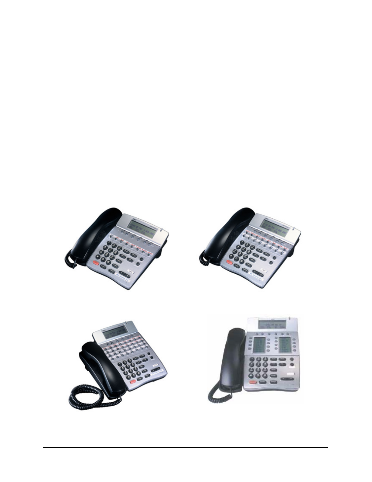
CHAPTER 3 TERMINALS
Dterm Series i (IP) Terminals
The Dterm IP gives you the freedom to tailor your platform and telephony applications for your
business even as the business grows and your needs expand. With its advanced digital circuitry , the
Dterm IP consists of several distinct models to meet users' diverse telephone terminal needs.
Dterm IP terminals are designed to provide ergonomic form and user-friendly functions. Dterm IP
terminals offer an adjustable LCD display unit with menu-driven soft key operation, allowing users
to program terminals at the desktop. The LCD panels are equipped with three lines of displ ay, each
with 245 characters. Standard features include headset jacks, wall mounts and adjustable base units.
Dterm IPs has four soft keys located just under the display of each ter minal. These menu-driv en soft
keys allow users convenient access too many telephony features. According to the status of the
multi-line terminal, functions of the soft keys are displayed in the third line on the LCD. If the status
of the terminal changes, the soft keys displayed will change automatically.
Dedicated function keys provide easy one-touch access to the most common telep hone operations.
These keys include: feature, recall conference, redial, hold, transfer, answer, speaker, microphone,
directory and message.
Dterm IP terminals are ideal choices for users that are connected through a managed IP network.
Dterm IP terminals are class B devices and comply with U.S. FCC regulations for office and
residential use as well as the Canadian Inference-causing Equipment Regulations.
8-Button Display 16-Button Display
32-Button Display 16-Button LD
NEAX 2000 IPS General Description Page 55
NDA-24345, Issue 3
Page 62

CHAPTER 3 TERMINALS
4-Button Display
Dterm IP Terminal Features
Dterm IP 4D
4 Line/Feature Access/ Programmable Feature Access Keys
9 Dedicated Function Keys: Feature, Recall, Conference, Redial, Hold, Transfer, Answer,
Speaker, Microphone
4 Local Soft Keys Controls (detail functions are dependent on PBX)
Dterm IP 8D
8 Line/Feature Access/ Programmable Feature Access Keys
11 Dedicated Function Keys: Feature, Recall, Conference, Redial, Hold, Transfer, Answer,
Speaker, Microphone, Directory, Message
4 Local Soft Keys Controls (detail functions are dependent on PBX)
Dterm IP 16D
16 Line/Feature Access/ Programmable Feature Access Keys
11 Dedicated Function Keys: Feature, Recall, Conference, Redial, Hold, Transfer, Answer,
Speaker, Microphone, Directory, Message
4 Local Soft Keys Controls (detail functions are dependent on PBX)
Dterm IP 16LD
16 Line/Feature Access/ Programmable Feature Access Keys
11 Dedicated Function Keys: Feature, Recall, Conference, Redial, Hold, Transfer, Answer,
Speaker, Microphone, Directory, Message
4 Local Soft Keys Controls (detail functions are dependent on PBX)
Dterm IP 32D
32 Line/Feature Access/ Programmable Feature Access Keys
11 Dedicated Function Keys: Feature, Recall, Conference, Redial, Hold, Transfer, Answer,
Speaker, Microphone, Directory, Message
4 Local Soft Keys Controls (detail functions are dependent on PBX)
Page 56 NEAX 2000 IPS General Description
NDA-24345, Issue 3
Page 63

CHAPTER 3 TERMINALS
Dterm IP Terminal Features
Display Features
Liquid Crystal Display (LCD) All Models: 3 lines by 24 Characters
Brightness Control LCD Contrast All Models: Yes
Adjustable LCD Display Dterm 8, 16, 16LD, 32 models only
Backlit Display Compatible Dterm 8, 16, 16LD, 32 models only
Receiver Volume Control
Handset All Models: Yes
Full Duplex Speaker Phone All Models: Yes
Ring Volume Control All Models: Yes
Miscellaneous
On-Line Firmware Upgradeable All Models: Yes
DHCP All Models: Client Support
Call Message Indicator All Models: Yes
Headset Dterm 8, 16, 16LD, 32 models only
Supported Adapters
Adjustable Base All Models: Yes*
Built-in Wall Mount All Models: Yes
Built-in Headset Jack Dterm 8, 16, 16LD, 32 models only
Housing Color: Black All Models: Yes
Housing Color: White Dterm 8, 16, 16LD, 32 models only
AD(A)-2R (Local Recording)
PS(A)-R (Local Line Survivable)
*For Dterm 4D - Terminal height can be adjusted with
removal/addition of the base unit.
NEAX 2000 IPS General Description Page 57
NDA-24345, Issue 3
Page 64

CHAPTER 3 TERMINALS
Dterm IP Terminal Specifications
Network Parameters
Internet Layer All Models: IPv4
IP Protocol All Models: NEC Peer-to-Peer (only)
Jitter Buffer All Models: Max 300msec (10msec steps)
Payload Interval All Models: 10ms ~ 40ms (10ms steps)
IP Addressing All Models: DHCP or Static Assignable
QoS All Models: 801.p, ToS and Diff-Service
Power Support Options
External All Models: AC: 24V, Current: 750mA
Operating Temperature All Models: 0 - 40 deg C (32 - 103 deg F)
Spare Pair Power All Models: Yes
In-Line Power All Models: Yes
External Power via
AC adapter
Quality of Service
All Models: Yes (Optional adapter)
All Models: Yes
Layer 2: 802.1p/Q; Layer 3: IP Precedence, Diff-Services
Dterm IP 4D
Dterm IP 8D
Dterm 16D
Dterm IP 16LD
Dterm IP 32D
Equipment Specification Size (W x D x H)
Tilt up: 7.57" x 8.69" x 5.57"
Tilt down: 7.57" x 8.69" x 3.80" (without stand unit)
Weight: 1.98lbs
Tilt up: 9.09" x 8.54" x 5.28"
Tilt down: 9.09" x 8.54" x 4.17"
Weight: 2.51lbs
Tilt up: 9.09" x 8.54" x 5.28"
Tilt down: 9.09" x 8.54" x 4.17"
Weight: 2.51lbs
Tilt up: 9.09" x 9.88" x 5.28"
Tilt down: 9.09" x 9.88" x 4.17"
Weight: 2.91lbs
Tilt up: 9.09" x 9.57" x 5.28"
Tilt down: 9.09" x 9.57" x 4.17"
Weight: 2.84lbs
Page 58 NEAX 2000 IPS General Description
NDA-24345, Issue 3
Page 65

Dterm IP Terminal Specifications
Dterm IP 4D
Voltage: 48V
Current: 90ma
Power Consumption: 4.32W
Audio Algorithm: G.711, G.729A
Protocol Support: 802.3af (CDP and NDP with ILPA integration)
10/100 base T (IEEE 802.3), RJ 45
Dterm IP 8D
Voltage: 48V
Current: 92ma
Power Consumption: 6.4W
Audio Algorithm: G.711, G.729A, G.723.1
Protocol Support: 802.3af and CDP (NDP with ILPA integration)
10/100 base T (IEEE 802.3), RJ 45 multi-port Switch
Dterm IP 16D
Voltage: 48V
Current: 92ma
Power Consumption: 6.4W
Audio Algorithm: G.711, G.729A, G.723.1
Protocol Support: 802.3af and CDP (NDP with ILPA integration)
10/100 base T (IEEE 802.3), RJ 45 multi-port Switch
Dterm IP 32D
Voltage: 48V
Current: 92ma
Power Consumption: 6.4W
Audio Algorithm: G.711, G.729A, G.723.1
Protocol Support: 802.3af and CDP (NDP with ILPA integration)
10/100 base T (IEEE 802.3), RJ 45 multi-port Switch
Dterm IP 16LD
Voltage: 48V
Current: 92ma
Power Consumption: 6.4W
Audio Algorithm: G.711, G.729A, G.723.1
Protocol Support: 802.3af and CDP (NDP with ILPA integration)
10/100 base T (IEEE 802.3), RJ 45 multi-port Switch
CHAPTER 3 TERMINALS
NEAX 2000 IPS General Description Page 59
NDA-24345, Issue 3
Page 66

CHAPTER 3 TERMINALS
Dterm Series i (TDM) Digital Terminals
The Dterm Series i Terminals are designed to provide ergonomic form and user-friendly functions.
With advanced digital circuitry, the Dterm Series i consists of distinct models to meet users' diverse
telephone terminal needs.
Dterm Series i Terminals offer adjustable display and non-display units with menu-driven soft key
operation, allowing users to program terminals at the desktop. Standard features include headset
jacks, wall mount units and adjustable base units. The display units are equipped with large LCD
panels with three lines of display, each with 24 characters. A 16-button backlit display version is
available for installations in dimly lighted areas such as restaurants, night clubs, and residential
applications. Easy to see in either dark or bright applications, the backlight feature may expand
installation opportunities and markets.
The Dterm Series i Display Terminals have four soft keys located just under the display of each
Terminal. These menu-driven soft keys allow users’ convenient access too many features. The state
of the terminal will determine what soft key is available to the user. According to the status of the
Multiline Terminal, functions of the soft keys are displayed in the third line on the LCD. If the status
of the Multiline Terminal changes, the soft keys displayed will change automatically.
Dedicated function keys provide easy one-touch access to the most common telep hone operations.
These keys include: Feature, Recall, Conference, Redial, Hold, Transfer, Answer, Speaker,
Microphone, Directory, and Message.
All Dterm Series i telephones are an ideal choice for both businesses an d remote users in residential
home offices. All Dterm Series i telephones are Class B devices and comply with U.S. FCC
regulations for office and residential use, and with requirements of the Canadian InterferenceCausing Equipment Regulations.
Page 60 NEAX 2000 IPS General Description
NDA-24345, Issue 3
Page 67

CHAPTER 3 TERMINALS
2-Button Non-Display 8-Button Non-Display
8-Button Display 16-Button Display
32-Button Display 60-Line DSS/BLF Console
NEAX 2000 IPS General Description Page 61
NDA-24345, Issue 3
Page 68

CHAPTER 3 TERMINALS
4-Button Display 16-Button LD
Standard features of the Digital models
• Large Message Waiting LED
• 24 Character, 3 Line LCD on display equipped models
• Tilt LCD Unit
• Adjustable Base
• Built-in Wall Mount Unit
• Built-in Headset Jack Connector
• 6 Programmable Ring Tones
• Speed Dial/DSS Buttons
• Programmable Line Keys with 2 Color LED
• Backlit Display on 16-Button Model
• Four Local Soft key Controls (detail functions are dependent on PBX, only provided on
terminals with display)
• Eleven dedicated Function Keys: Feature, Recall, Conference, Redial, Hold, Transfer,
Answer, Speaker , Mic*, Directory*, and Message*. (*Functionality dependant upon system
software.)
• Built-in Half Duplex Handsfree Unit
• Snap-in Options Available:
- AP(R): Analog TEL connection with Ringing Signal Generation
- AP(A): Analog TEL connection without Ringing Signal Generation or Disconnect Signal
- AD(A): Tape-recorder connection
- CT(A): CTI Adapter, RS-232-C (9-pin) interface
- IP-R: V oIP Adapter
Page 62 NEAX 2000 IPS General Description
NDA-24345, Issue 3
Page 69

Series i Multi-line Terminal Descriptions
CHAPTER 3 TERMINALS
DTR-2DT (BK) TEL
DTR-2DT (WH) TEL
DTR-4D (BK) TEL
DTR-8 (BK) TEL
DTR-8 (WH)TEL
DTR-8D (BK) TEL
DTR-8D (WH) TEL
DTR-16D (BK) TEL
DTR-16D (WH) TEL
2 LINE TERMINAL - available in black (BK) or white (WH).
(does not support optional adapters)
Fully modular with 2 Flexible, 2-color LED Line keys, eight Function
Keys, built-in Speakerphone, electronic volume and tone controls.
4 LINE TERMINAL – available in black (BK) only.
Fully modular with 4 Flexible, 2-color LED Line keys, eight Function
Keys, built-in Speakerphone, 24-character by 3-line display, four
softkeys, Large LED, Electronic Volume and Tone Controls.
8 LINE TERMINAL – available in black (BK) or white (WH).
Fully modular with 8 Flexible, 2-color LED Line keys, eight Function
Keys, built-in Speakerphone, headset jack, wall mount unit, four
softkeys, Large LED, Electronic Volume and Tone Controls and tilt
stand.
8 LINE DISPLAY TERMINAL - available in black (BK) or white (WH).
Fully modular with 8 Flexible, 2-color LED Line keys, eight Function
Keys, built-in Speakerphone, headset jack, wall mount unit, 24character by 3-line display, four softkeys, Large LED, Electronic
Volume and Tone Controls, and tilt stand.
16 LINE DISPLAY TERMINAL - available in black (BK) or white (WH).
Fully modular with 16 Flexible, 2-color LED Line keys, eight Function
Keys, built-in Speakerphone, headset jack, wall mount unit, 24character by 3-line display, four softkeys, Large LED, Electronic
Volume and Tone Controls and tilt stand.
DTR-32D (BK) TEL
DTR-32D (WH) TEL
DCR-60 (BK)
CONSOLE
DCR-60 (WH)
CONSOLE
32 LINE DISPLAY TERMINAL - available in black (BK) or white (WH).
Fully modular with 32 Flexible, 2-color LED Line keys, eight Function
Keys, built-in Speakerphone, headset jack, wall mount unit, 24character by 3-line display, four softkeys, Large LED, Electronic
Volume and Tone Controls and tilt stand.
ATTENDANT ADD-ON CONSOLE - Requires an AC-R ADP
(included).
Fully modular with 48 programmable, 2-color LED keys (for station
trunk appearances), 12 Function keys with red LED, and tilt stand.
Terminal available in: black (BK) or white (WH).
NEAX 2000 IPS General Description Page 63
NDA-24345, Issue 3
Page 70

CHAPTER 3 TERMINALS
Specification for Series i Digital Terminals
Item Description
Curl Cord Length 12ft
Weight (no handset) 510g (min.)
LCD Display
Ringing Sound Level
Built in Hands Free Half duplex
Items Provided with Instrument Line cord, Directory card
Handset Cradle K type compatible
LCD angle
Housing Face Angle
Recommended Headset NEC Headsets
Other HAC
24 digit x 3 line (alphanumeric and some
characters) no back light
Max. 80dBSPL (in output limit condition)
Max. 86dBSPL (in normal condition)
14~42.5 deg. (on the desk, no housing tilt)
25~53.5 deg. (on the desk, housing tilt up)
-4.4 deg. (wall mounting)
14~25 deg. (on the desk)
-4.4 deg. (wall mounting)
Dterm Series i Digital Terminal Options
Item Description
WM-R Unit
AD(A)-R Unit
AP( R)-R Unit
Series i Multi-line Terminals with an AP(R)-R, AP (A)-R, CT (A)-R,
and/or an IP-R Unit can be wall mounted using the WM-R Unit.
Provides Series i Multi-line Terminals ability to interface with
recording device.
Provides Series i Multi-line Terminals ability to interface with analog
device such as a cordless telephone, facsimile machine, external
speakerphone, Automatic Dialer or modem. Provides ringing to
analog device connected. Requires an AC-R ADP.
Provides Series i Multi-line Terminals ability to interface with analog
AP(A)-R Unit
CT(A)-R Unit
IP-R Unit
AC-R Unit AC adapter for DSS/BLF Console, AP(A), AP(R), or IP-R Unit
device such as a cordless telephone, facsimile machine, external
speakerphone, Automatic Dialer or modem. No ringing is provided.
Connects a Series i Multi-line Terminal to a PC providing a complete
turnkey package with graphical telephone user interface and call
logging. Shipped with Multi-line Phone Kits software. Supports
Serial interface.
A compact plug-and-play device that installs into the base of a Dterm
Series i display terminal. Integrated two-port 10/100baseT Ethernet
pass through hub that permits using one port to connect the network
interface card (NIC) from the PC to the IP network. The other is
plugged directly into a LAN or an IP network device such as a router,
DSL modem or cable modem. Requires an AC-R ADP.
Page 64 NEAX 2000 IPS General Description
NDA-24345, Issue 3
Page 71

Dterm Series i Line Conditions
Cable Length Note 2 Standard with AC Adapter
Dterm Series i
Dterm 8 / 8D
CHAPTER 3 TERMINALS
8DLC 300m (984ft)
4DLC 300m (984ft) 1200m (3937ft)
2DLC 850m (2789ft) 1200m (3937ft)
Note 2
Dterm 16/16D
Dterm 32/32D
DSS/BLF Console
Note 3
8DLC 200m (656ft)
4DLC 200m (656ft) 1200m (3937ft)
2DLC 850m (2789ft) 1200m (3937ft)
8DLC 200m (656ft)
4DLC 200m (656ft) 1200m (3937ft)
2DLC 850m (2789ft) 1200m (3937ft)
8DLC - 300m (984ft)
4DLC - 1200m (3937ft)
2DLC - 1200m (3937ft)
Note 2
Note 2
Note 1: Cable length is based on the following conditions.
• Diameter of the cable is 0.5 mm.
• The Protection arrester is not inserted between the terminal and PBX.
Note 2: When using 8DLC card, it is not available for long line function, even if it is equipped with AC
Adapter.
Note 3: The DSS/BLF Console requires local AC/DC supply.
NEAX 2000 IPS General Description Page 65
NDA-24345, Issue 3
Page 72

CHAPTER 3 TERMINALS
Dterm Series E (TDM) Digital Terminals
The Dterm Series E terminals are designed to provide ergonomic form and user-friendly functions.
With advanced digital circuitry, the Dterm Series E consists of distinct models to meet users' diverse
telephone terminal needs.
Dterm Series E terminals offer adjustable display and non-display units with menu-driven soft key
operation, allowing users to program terminals at the desktop. The display units are equipped w ith
large LCD panels with three lines of display, each with 24 characters. Each terminal offers an
optional full duplex speaker phone operation for two-way conversation. Standard features include
headset jacks, wall mount units and adjustable base units.
The Dterm Series E Display Terminals have four soft keys located just under the display of each
Terminal. These menu-driven soft keys allow users convenient access too many features. The state
of the terminal will determine what soft key is available to the user. According to the status of the
Multiline Terminal, functions of the soft keys are displayed in the third line on the LCD. If the status
of the Multiline Terminal changes, the soft keys displayed will change automatically.
Page 66 NEAX 2000 IPS General Description
NDA-24345, Issue 3
Page 73

CHAPTER 3 TERMINALS
Dterm Series E Terminals
8-Line Non-Display 8-Line Display
16-Line Display 32-Line Display
60-Line DSS/BLF/Add-On Module
NEAX 2000 IPS General Description Page 67
NDA-24345, Issue 3
Page 74

CHAPTER 3 TERMINALS
Dterm Series E Terminals
8-Line Non-Display
8 programmable line/feature keys with two-color LED indication
8 dedicated Function Keys
Built-in speakerphone
ADA compatibility
Large Message waiting LED
This terminal is available in Black (BK) or White (WH).
8-Line Display
8 Programmable line/feature keys with two-color LED
8 dedicated Function Keys
Built-in speakerphone
ADA compatibility
Large Messaging Waiting LED
24-character, 3-line, adjustable Liquid Crystal Display (LCD)
Four Softkeys
This terminal is available in Black (BK) or White (WH).
16-Line Display
16 Programmable line/feature keys with two-color LED
8 dedicated Function Keys
Built-in speakerphone
ADA compatibility
Large Messaging Waiting LED
24-character, 3-line, adjustable Liquid Crystal Display (LCD)
Four Softkeys
This terminal is available in Black (BK) or White (WH).
32-Line Display
16 Programmable line/feature keys with a two-color LED
16 SPD/DSS keys with two-color LED
8 dedicated Function Keys
Built-in speakerphone
ADA compatibility
Large Messaging Waiting LED
24-character, 3-line, adjustable Liquid Crystal Display (LCD)
Four Softkeys
This terminal is available in Black (BK) or White (WH).
60-Line DSS/BLF/Add-On Module
60 programmable line keys (each with a two-color LED)
This terminal is available in Black (BK) or White (WH).
Page 68 NEAX 2000 IPS General Description
NDA-24345, Issue 3
Page 75

CHAPTER 3 TERMINALS
DTERM SERIES E FEATURES
• Four Local Soft key Controls (detail functions are dependent on PBX)
• Large Message Waiting LED
• 24 Character, 3 Line LCD
• Tilt LCD Unit
• Adjustable Legs
• Built-in Wall Mount Unit
• Built-in Headset Jack Connector
• Speed Dial/DSS Buttons
• Programmable Line Keys with 2 Color LED
• Eight dedicated function keys (Feature, Recall, Conf, Redial, Hold, Transfer, Answer &
Speaker)
• Built-in Half Duplex Handsfree Unit
• Optional: Full Duplex HFU (consist of HFU-U Unit, External Microphone Unit and AC
adapter)
• Snap-in Options Available:
- ADA-U (Ancillary Device Adapter)
- APR-U (Analog Port Adapter with Ringing)
- HFU-U (External Handsfree Unit)
- ACA-U (AC Adapter Unit)
- WMU-U (External Wallmount Unit)
- WMU-W (External Wallmount Unit for DTP-2 Terminals)
NEAX 2000 IPS General Description Page 69
NDA-24345, Issue 3
Page 76

CHAPTER 3 TERMINALS
Dterm Series E Digital Terminal Options
Item Description
ADA-U UNIT
APR-U UNIT
Ancillary Device Adapter, Used for External Recording
Devices
Analog Port Adapter with Ringing, used to connect external
analog devices such as PC Modem, analog Cordless etc.
Requires ACA-U Unit for local power.
Analog Port Adapter without Ringing, Used for external
APA-U UNIT
speakerphones.
Requires ACA-U Unit for local power when the connected
device is over
50 ft. from the APA-U Unit.
HFU-U UNIT Full duplex Speakerphone with external microphone.
CTA-U CTI Adapter Unit
ACA-U UNIT
WMU-U UNIT
AC Adapter provides local power for APR-U Unit, APA-U
Unit, CTA-U Unit, HFU-U Unit, IPW-U Unit, DESKCON, and
Dterm long line.
Wall Mount Unit, Required when using terminal adapters
attached to phone. If not using terminal adapters built-in
wall mount in phone is used.
The IPW-2U (ELC) adapter is a full duplex switch, which
can be installed on any of the Dterm Series E display
IPW-2U (ELC)
phones. With this adapter, you can upgrade the 8, 16, 32button Dterm Series E terminals to VoIP when using the
PN-32IPLA (ELC) IP station card.
The IPW-2U (P-P) adapter is a full duplex switch, which can
be installed on any of the Dterm Series E display phones.
IPW-2U (P-P)
With this adapter, you can upgrade the 8, 16, 32-button
Dterm Series E terminals to VoIP when using Peer to Peer
connection.
Page 70 NEAX 2000 IPS General Description
NDA-24345, Issue 3
Page 77

CHAPTER 3 TERMINALS
Dterm Series E Line Conditions
Loop Resistance Note 1
Standard 600 ohms Analog
Telephone Set
Trunk
Cable Length Note 2 Standard with AC Adapter
Dterm Series E
Electra Elite
Operator
Position
Option 2,500 ohms
Exchange Line 1,700 ohms Loop Start
Tie or DID Line 2,500 ohms
Dterm 8 / 8D
Dterm 16/16D
Dterm 32/32D
Dterm 8D-1IP
Dterm 16D-1IP
Dterm 32D-1IP
DSS/BLF Console
Note 4
Attendant Terminal
SN716
Desk Console
8DLC 300m (984ft)
4DLC 300m (984ft) 1200m (3937ft)
2DLC 850m (2789ft) 1200m (3937ft)
8DLC 200m (656ft)
4DLC 200m (656ft) 1200m (3937ft)
2DLC 850m (2789ft) 1200m (3937ft)
8DLC 200m (656ft)
4DLC 200m (656ft) 1200m (3937ft)
2DLC 850m (2789ft) 1200m (3937ft)
_ Max. 328 ft. between Ether/IP-PAD and
Router/ Switching Hub
_ Max. 328 ft. between Ether/IP-PAD and
Router/ Switching Hub
_ Max. 328 ft. between Ether/IP-PAD and
Router/ Switching Hub
8DLC - 300m (984ft)
4DLC - 1200m (3937ft)
2DLC - 1200m (3937ft)
Same as Dterm Series E
8DLC 300m (984ft)
4DLC 350m (1148ft) 1200m (3937ft)
2DLC 350m (1148ft) 1200m (3937ft)
Note 3
Note 3
Note 3
Note 3
Note 1: Loop resistance includes an internal resistance of telephone set or distant exchange.
Note 2: Cable length is based on the following conditions.
Diameter of the cable is 0.5 mm.
The Protection arrester is not inserted between the terminal and PBX.
Note 3: When using 8DLC card, it is not available for long line function, even if it is equipped with AC
Adapter.
Note 4: The DSS/BLF Console requires local AC/DC supply.
NEAX 2000 IPS General Description Page 71
NDA-24345, Issue 3
Page 78

CHAPTER 3 TERMINALS
Dterm Cordless Terminals
With the NEC Cordless product line, the distance of your handset cord does not govern y our work
area. The mobility, convenience and reliability of these cost-effective telephones empower
employees to answer calls regardless of their location. Potential customers do not waste time playing
telephone tag, and employees are not glued to their desk waiting for that all-important call. Business
is not lost because of callers being able to reach a live person. The NEC Cordless application is th e
ideal solution for those businesses that require mobility but do not want to invest in a full-blown
wireless solution.
Dterm Headset Cordless Dterm Cordless II
Dterm Cordless Lite II Dterm Analog Cordless
Dterm Handset Cordless Terminal
Page 72 NEAX 2000 IPS General Description
NDA-24345, Issue 3
Page 79

CHAPTER 3 TERMINALS
DTERM HEADSET CORDLESS
The analog Dterm Headset Cordless telephone is designed for mobility. Its convenient pocket size
allows you to speak and listen in a handsfree mode. Designed and engineered using the 2.4 GHz
frequency range, the Dterm Headset Cordless provides clear and secure conversations. The
extremely small "handset" measures just 2.13 x 0.61 x 3.39 inches. For added value, the unit comes
equipped with two 2.5 mm headsets. In add it ion, th e Dt erm Headset Cordless offers such features as
a 100-number phone book, a 3-line, 16-character backlit handset display, one-touch dialing and
vibration alert mode. With its flexible, unique design and rich feature set, NEC's new hands-free
cordless headset is a powerful executive business terminal.
Dterm Headset Cordless Features
2.4 GHz Digital Spread Spectrum Technology
Phonebook Locations (up to 100 numbers in total)
Trilingual Language Option
8-Day Standby Battery Life
5-Hour Talk T ime
Tone/Pulse Dialing
Handset Earpiece and Ringer Volume Control
32-Digit Redial / 3 Last Number Redial Locations
3-Line, 16-Character Backlit Handset Display
One Touch Dialing
Mute Feature
Flash and Pause
Find Handset
Call Timer
Vibration Alert Mode
AutoTalk - AutoTalk allows you to answer calls by removing the handset from the base.
AutoStandby - AutoStandby allows you to hang up by simply returning the handset to the
base.
Rando m Code - Rando m Code protects you against misbilled calls w hich might result from
your telephone being activated by other equipment. The Dterm Headset Cordless has
digital security which automatically selects one of over 65,000 digital security codes for the
handset and base.
Rock etDial - RocketDial is a one-touch speed dial key that automatica lly dials your most
important or frequently called number. The number dialed is a preset number stored by the
user.
Two headsets included: one over-the-head, one over-the-ear
Beltclip
Charging Base with an AC Adapter included
Dterm Headset Cordless Specifications
Size: 2.13 x 0.61 x 3.39 inches
2.5mm Headset Connection
2.4 GHz Digital Spread Spectrum Technology
5-Hour Talk T ime
8-Day Standby Battery Life
3.7V, 650mAh Lithium Ion Battery
32-Digit Redial
3 Last Number Redial Locations
3-Line, 16-Character Backlit Handset Display
NEAX 2000 IPS General Description Page 73
NDA-24345, Issue 3
Page 80

CHAPTER 3 TERMINALS
DTERM CORDLESS II
Dterm designed for employees who need digital multiline desktop functionality in a cordless
handset. The 2x16 line display provides valuable calling information. The Dterm Cordless II is
designed to eliminate noise and provides a range of up to 350 feet.
Dterm Cordless II Telephone Features
Advanced Digital Technology eliminates noise and provides an extended range.
Direct interface to digital interface port on NEC telephone systems.
Pr ogrammable Function Keys let you utilize features of your telephone system with the
Dterm Cordless Multiline Terminal.
2x16 Digit LCD displays messages, including caller name and number.*
Conference calling saves time and improves office communication.
Compatibility enhances the Electra Professional®, NEAX® 2000 and NEAX 2400
telephone systems.
Mess age LED indicates me ss ages in voice mail.
Headset jack for hands-free operation.
Hold mode for handling multiple calls.
Transfer function for switching lines.
Color- black
Note: Different displays - The Dterm Cordless II Multiline Terminal handset operates with the
NEC Electra Professional, NEAX 2000 and NEAX 2400 systems supporting the Dterm Series
III/E/i interface. Connection with each system will result in system-specific displays.
*Dterm Cordless II Multiline Terminal will display caller name or number if Caller ID is a feature of the
host system.
Dterm Cordless II Specifications
The Dterm Cordless II complies with FCC and IC parts 15 and 68.
General:
Frequency Control: Phase Lock Loop
Modulation: Spread Spectrum
Operating Temp: 0° to 50° C (32° to 122° F)
Output Power: 63 mW
Occupied Bandwidth: 1,600 kHz
Data Transmission Speed: 688 bps
Base Unit:
Receive/Transmit Freq.: 902 MHz - 928 MHz
Power Requirements: 10 Vdc from supplied AC adapter
Size: 4-1/4 in. W x 7-1/2 in. D x 2-1/4 in. H
Weight: approximately 15.4 oz.
Handset:
Receive/Transmit Freq.: 902 MHz - 928 MHz
Power Requirements: Nickel-Cadmium Battery Pack
Battery Charger:
Power Requirements: 9V DC from supplied AC adapter
Size: 2-1/5 in. W x 1-2/3 in. D x 8-2/3 in. H (with antenna)
Page 74 NEAX 2000 IPS General Description
NDA-24345, Issue 3
Page 81

CHAPTER 3 TERMINALS
DTERM CORDLESS LITE II
Dterm designed for employees who need digital multiline desktop functionality in a cordless
handset. The 2x16 line display provides valuable calling information. The Dterm Cordless Lite is
designed to eliminate noise and provides a range of up to 150 feet. The Dterm Cordless Lite is ideal
when the range of the Dterm Cordless II is not required.
Dterm Cordless Lite II Features
900 MHz FM with ADPCM
2-line, 16-digit LCD Display
Dterm Cordless Lite II Headset Jack
Channel Selection Control
Ringer Volume Control
Handset V olum e Control
Single Key Access to: Conference, Hold, Transfer, and Mute features
Four Programmable Keys: F1-F4
Separate Charging Stand with Spare Battery Charging Capability
Auto Standby
AutoTalk
Silent Alarm
Out of Range Protection
Low Battery Protection System
Key Pad Lock Feature
Wall Mountable Separate Base Unit
Wall Mountable Separate Charging Unit
Easy Installation
Compact Handset Design
Use with an NEC Digital Multiline Terminal or as a stand-alone device
Dterm Cordless Lite II Telephone Specifications
General:
Frequency Control: Phase Lock Loop
Modulation: 900 MHz FM with ADPMC (digital)
Operating Temperature: 0° to +50° C (+32° to +122° F)
Bandwidth: 50 kHz
Data Transmission Speed: 688 bps
Base Unit:
Receive/Transmit Frequency: 902 MHz - 928 MHz
Power Requirements: 10 Vdc from supplied AC adapter
Size: 4-1/4 in. W x 7-5/8 in. D x 2-1/4 in. H
Weight: Approximately 13.7 oz.
Handset:
Receive/Transmit Frequency: 902 MHz - 928 MHz
Power Requirements: NiMH Battery
Size: 2 in. W x 1-1/4 in. D x 5-1/2 in. H (with antenna)
Weight: Approximately 5.2 oz. with battery
Battery: 700 mAh, 3.6V
Talk Mode: 6 hours (typical)
Standby Mode: 5 days (typical)
Battery Charger:
Power Requirements: 9V DC from supplied AC adapter
Size: 1-3/8 in. W x 1-1/2 in. D x 2-1/4 in. H
NEAX 2000 IPS General Description Page 75
NDA-24345, Issue 3
Page 82

CHAPTER 3 TERMINALS
ANALOG CORDLESS
This is the ideal choice for employees that would benefit from mobility but do not require the power
and versatility of a digital telephone. The Dterm Analog Cordless offers a highly affordable NE C
analog solution and easy access too many system features. This is a 2.4 GHz digital spread spectrum
cordless solutions with built in speed dial and dedicated feature buttons offering the benefits of a
cordless at an analog price.
Analog Cordless Features
2.4 GHz Digital Spread Spectrum
30-Channel Autoscan
10-Number Memory Dialing
Desk or Wall Mountable
Tone/Pulse Dialing
Handset V olum e Control
32-Digit Redial
Page/Find
AutoTalk -- AutoTalk allows you to answer a call by just removing the handset from the
base so you do not have to waste time pushing buttons or flipping switches.
AutoStandby™
Analog Cordless Specifications
The Analog Cordless complies with FCC parts 15 and 68.
General:
USOC Jacks: RJ-11C
Frequency Control: Phase Lock Loop
Modulation: Direct Sequence Spread Spectrum
Operating Temp.: 0° - 50° C (32° to 122° F)
Handset:
Transmit Frequency: 2,416.128 MHz - 2,475.520 MHz
Receive Frequency: 2,406.912 MHz - 2,466.304 MHz
Power Requirements: Rechargeable nickel-cadmium battery pack
Size: 2-1/4 in. W x 1-1/2 in. D x 8-1/2 in. H (with antenna)
Weight: approximately 8.8 oz with battery
Battery Capacity: 600 mAh, DC3.6V
Talk Mode: 6 hours (typical)
Standby Mode: 4 days (typical)
Base Unit:
Transmit Frequency: 2,406.912 MHz - 2,466.304 MHz
Receive Frequency: 2,416.128 MHz - 2,475.520 MHz
Power Requirements: 9V DC from supplied AC adapter
Size: 4-1/4 in. W x 7-1/2 in. D x 2-1/4 in. H
Weight: approximately 15.4 oz.
Page 76 NEAX 2000 IPS General Description
NDA-24345, Issue 3
Page 83

CHAPTER 3 TERMINALS
DTERM HANDSET CORDLESS TERMINAL
The Dterm H andset Cordless operates in the 900 MHz analog spectrum and is compatible with the
NEAX 2000 IPS, NEAX 2400, and IPK (2-wire station interface). For the clearest reception
possible, the handset automatically selects from one of 40 channels to communicate with its base
unit. It is also possible to change channels manually should a conversation become distorted while
talking. Up to 40 Dterm Handset Cordless telephones may access the 40 channels simultaneously.
The recommended range or distance between the handset and base unit is 30 - 100 feet, depending
upon the environment. This range is ideal for employees who need mobility around their immediate
workspace.
Each NEC Dterm Handset Cordless Telephone consists of a base unit, cordless handset, belt clip and
a standard rechargeable nickel-cadmium battery that supports 4 hours of talk time or 40 hours of
standby. The optional headset may be easily connected to the 2.5mm headset connector on the
handset.
Calls may be initiated, transferred and conference using the dial pad of the cordless handset. Users
always have the option to perform call-handling functions on the base of their Handset Cordless
phone, just as they would on a corded Dterm.
Dterm Handset Cordless Terminal
Fully modular 900 MHz Analog FM spectrum with Voice scramble
40 separate voice chann els
16 programmable line/feature keys with two-color LED indication
8 Dedicated Function Keys
4 Softkeys
24-character by 3-line Display
Large Message waiting LED
Built-in Speakerphone
Electronic V olume/Tone Controls
Base Unit
Belt Clip
Battery
RF line cord
ADA compatibility
standard nickel-cadmium battery (40 hours of standby talk time)
Users always have the option to perform call handling functions on the base of their Cordless
Handset phone, just as they would on a corded Dterm.
NEAX 2000 IPS General Description Page 77
NDA-24345, Issue 3
Page 84

CHAPTER 3 TERMINALS
Wireless Dterm PS Handset
DTERM PS (Personal Station)
The Dterm PS offers portability, clear digital signal quality and has the same features of a desktop
phone. Weighing less than 4 oz. with 6 hours of continuous talk time and 300 hours on standby , the
Dterm PS phone has been uniquely designed for people on the run. The Dterm PS provides the
freedom and convenience of a mobile phone with the advantages and features of a desktop handset.
• Continuous coverage – walk freely around your workplace while on a call.
• No static or fading – audio quality indistinguishable from a desktop phone.
• Small lightweight handset with long battery life.
• Low power operation for compatibility in any environment.
• Up to 512 PS Handsets
• 216 PS Simultaneous Connections
Page 78 NEAX 2000 IPS General Description
NDA-24345, Issue 3
Page 85

DTERM PS (Personal Station)
PS Handset
CHAPTER 3 TERMINALS
Dterm PS Features
• 2-Line Operation with Number Sharing
• Voice Mail Message Waiting
• Calling Party Name and Number display
• Support for Wireless Roaming
• Call Hold & Transfer
• Directory Dial (100 entries with name)
• Speed Dial (20 entries with name)
• Calling Party Number Redial & Last Number Redial (5 entries each)
• Headset Operation with Automatic Answer
• Vibration Alert
• Support for Modem Data
• 2 line, 11 Digit LCD Display (with scrolling)
• User-defined soft keys
And the provisioning of the Dterm PS data port facility to allow software updates protects your
investment.
NEAX 2000 IPS General Description Page 79
NDA-24345, Issue 3
Page 86

CHAPTER 3 TERMINALS
Accessories for the Dterm PS
• Standard Battery Charger Base Unit
• Lithium-ion Battery (provides up to 4 hours of continuous talk-time and 300 hours on
standby)
• Leather Cases
- Leather Case with Swivel Clip - Includes a Swivel Belt Clip with Quick Release
- Leather Case with Fixed Clip Includes a fixed Belt Clip
Both cases offer an Integrated D-Ring for use with the optional adjustable necklace. The
adjustable necklace (from 23" to 42") provides security from dropping the handset while,
for example, carrying it in a lab coat pocket.
• Dterm PS Headset
- Head band type
- Single ear cover
- 47" cord
The Dterm PS Headset is a classic banded headset with a microphone extension. The
Dterm PS Headset is typically used in cases of prolonged active use (for example,
customer service agents).
• Dterm PS Ear Piece
- Lower profile Ear Bud receiver
- In-line Microphone
- 47" cord
The Dterm PS Ear Piece is an ear-bud type with an in-line microphone. The Ear Piece is
for occasional use or where concealment is desired (for example, hotel security).
• Dterm PS Modem Cable
- Connects to the modem jack of your laptop or palmtop
- Supports speeds up to 19.2Kbps
- Autodial from PC Application (Application must support dialing without waiting
for dial tone)
• Dterm PS Assistant Software - The Dterm PS Assistant software and interface cable will
allow you to enter the directory and speed-dial entries on your PC and upload to your
Dterm PS.
You can now:
- Enter, Synchronize and backup your Directory and Speed Dial entries
- Copy and paste entries from your Desktop Organizer and upload to your Dterm
PS.
- "Clone" all or some of your Dterm PS handset Directory and Speed Dial entries,
so everyone in your organization has access to key personnel and department
phone numbers.
There are two versions available: Dterm PS Personal Assistant and the Dterm PS Group
Assistant. The Personal Assistant supports only one Dterm PS handset while the Group
Assistant is designed to manage and maintain Directory and Speed Dial entries for an
entire workgroup. The PS Interface Cable connects to the PC serial port and to the
Dterm PS interface port, on the bottom of the handset.
Page 80 NEAX 2000 IPS General Description
NDA-24345, Issue 3
Page 87

CHAPTER 3 TERMINALS
Dterm SoftPhone (SP20)
The NEC SP20 with the USB headset allows you to make and receive calls over a VoIP network
using a NEC Dterm Series graphical user interface displayed on your laptop. The NEC Dterm SP20
SoftPhone is an ideal solution for employees who are out of the office frequently traveling on
business, workers that work both at home and in the office as well as those who require the
interaction of data with their work such as a remote ACD agents.
The Dterm SP20 is a full-featured Internet telephone that places calls over a VoIP network using a
Dterm series graphical user interface (GUI) displayed on the laptop. It is an ideal solution for
employees who work at home, employees who travel frequently, or remote ACD agents who require
the interaction of data.
The SP20 SoftPhone has three different types of skin displays. Users have their choice of displays,
which look just like the Dterm Series E terminals (in either black or white) as a virtual type of phone,
or a customizable graphical user interface. No matter which phone y ou use as your display, features
and functions that existed on the Dterm hardware set are transported to the SP20 upon activation.
NEAX 2000 IPS General Description Page 81
NDA-24345, Issue 3
Page 88

CHAPTER 3 TERMINALS
Key Features and Benefits
The Dterm SP20 offers a full complement of station features and impressive voice quality over IP for
this important segment of mobility and PC-based applications. Most of the features and functions,
which exist on the IP Dterm and/or IP enabled Dterm can be instantly transported to the SoftPhone.
Basic features offered by the Dterm SP20 include:
Configurable for Peer-to-Peer or Protims IP for IPELC Voice Communications
No need to load new software in order to operate a different protocol. The Dterm SP20 supports
both Protims IP and peer-to-peer. Administrators are able to invoke the protocol via the Dterm
SP20 control.
Powerful User Interface (Dterm SP20 and Java GUIs) with a NEC Hardware
Terminal Appearance
The Dterm SP20 provides a user configurable GUI (Graphical User Interface), enabling the user
to access telephone features. Most of the procedures are easy to perform by selecting the buttons
on the screen with the mouse. The display may be freely customized in order to create an
environment best suited for specific requirements.
Displays call records in Quick Reference List via the Call Log Window
All calls are recorded one by one in the call log. You can find at a glance when and with whom
you talked. The Dterm SP20 also offers a call memo function whereby y ou can record the key
points of the call so that you can visually identify the individual records.
Recording Function
Use the personal computer in pla ce of a tape reco rder to record the contents of a ca ll. Record th e
contents of a call in a sound file and reproduce the saved contents of a call anytime from the call
log window. Since the file is stored as a .wav file, you can e-mail and forward it to other
personnel for their listening pleasure.
Macro Function for Launching or closing Dterm SP20
The macro function will enable the user to launch related applications, which might run
simultaneously with the Dterm SP20. One selection and all applications are launched.
Support for multiple algorithms
The Dterm SP20 supports both G.711 and G.729A compression algorithms.
PBX support
The Dterm SP20 is capable of being programmed for either a peer-to-peer or IPELC
configuration.
IPELC Software licenses requirements
Software seat requirements for the IPELC configuration are based on a dongle implementation.
There is no PBX IP seat licenses required for the Dterm SP20 IPELC operation. The number of
licenses depends on the type of licenses key purchased.
The dongles are pre-configured for the following number of licenses:
- 10-seat license
- 20-seat license
- 40-seat license
- 100-seat license
Peer to Peer software licenses requirements
In a peer-to-peer Dterm SP20 configuration, all the software seats are assigned via the PBX. The
PBX will require an IP seat license and concurrent seat available in order to activate each
softphone.
Page 82 NEAX 2000 IPS General Description
NDA-24345, Issue 3
Page 89

CHAPTER 3 TERMINALS
Dterm SP20 System Requirements
Protims over IP
32IPELC Card and 16VCT Card for compression
Dterm SP20 Software CD
External Licensing server via dongle
NEAX 2000 IPS, 3200 Series software or higher
SoftPhone 4 seat Licenses : per 4 clients
8 Hardware seat licenses: Only required when seat is not available
Dterm SP20 Software CD
Computer Requirements
Computer: IBM-PC/AT or Compatible
Operating System: Windows XP,2000(SP2),NT4.0 (SP4), ME, 98, 95 English Version
Note: NT4.0 cannot support USB headset
CPU: Pentium II or greater
Memory: 128Mb or more
Hard Disk: Free Capacity 10Mb or more
CD-Rom Drive: Quad or Faster
Mouse: Window compatible point device
Display Resolution: VGA or higher resolution
Network Interface Card: 10/100base -T
Printer Port: Parallel (Indispensable)
USB Port: USB Headset for Plantronics
DSP 300 or DSP 400.
NEAX 2000 IPS General Description Page 83
NDA-24345, Issue 3
Page 90

CHAPTER 3 TERMINALS
Dterm SoftPhone (SP30)
The Dterm SP30 allows customers to capitalize on the advantages of a converged voice and data
network whether they’re in the office or on the road. The Dterm SP30 combines traditional business
communication needs with the data applications your customers require.
The Dterm SP30 optimally delivers high quality voice via a USB-connected headset. With a simple
drag and drop, the Dterm SP30 allows telephone dialing from other telephone directory applications
such as Microsoft Outlook®, HTML pages and Word® documents, etc. In addition, the Dterm SP30
provides an interface to Microsoft’s Telephony Application Programmin g Interface (TAPI) via NEC
OpenWorX integration, allowing TAPI-enabled applications, such as Outlook and ACT, to make and
receive calls. The Dterm SP30 has the ability to use a wireless handset (PS) for all voice connections
instead of the USB handset. The Dterm SP30 can be displayed in 1 of 4 different colors (black, red,
gold and neon blue) in order to reflect the “personality” of the day. The Dterm SP30 also allows for 3
different modes of operation.
Maximized mode: Access to full line of softphone features such as application sharing,
member lists, conference mode, chatting capabilities, Internet access and many others are just
one click away.
Compact Mode: L-shaped user interface, operating in a s mall footprint on the PC screen.
Compact view allows the softphone to remain active while another application window such as
a Word document; database file or email is the primary focus on the PC. With the compact
view, the most popular features of the converged softphone are just a click away.
Task Mode: The softphone can be minimized and shown as a task within a Microsoft
Operating System. While operating in this mode, the softphone will output an audio
notification to the user upon receiving an incoming call. It will be up to the user to utilize the
hot key in order to activate the D
term
SP30 application and answer the call.
Page 84 NEAX 2000 IPS General Description
NDA-24345, Issue 3
Page 91

CHAPTER 3 TERMINALS
NEAX 2000 IPS General Description Page 85
NDA-24345, Issue 3
Page 92

CHAPTER 3 TERMINALS
Key Features and Benefits
The Dterm SP30 offers a full complement of station and converged features for an important
segment of mobility and PC-based applications. Even though a majority of the hardware telephone
features function on the softphone, the main focus for the softphone is its ability to deliver PC
capabilities to the telephone.
Displays call records in Quick Reference List via the Call Log Window: All calls are
recorded in a Call Log. Telephone number, date of the call and identification as to whether or not
the call was received and answered are all logged. You can find at a glance when and with whom
you talked. The Dterm SP30 also offers a call memo function whereby y ou can record the key
points of the call so that you can visually identify the individual records.
Links with PC applications: Now you can collaborate on a white board application (Word
or Excel
®
document or any other application) that is operating on your PC and the PC at a distant
®
site. Simply place a call to the far-end D term SP30 user and activate the applicatio n you will be
collaborating on. You are now able to have a more productive conversation.
Internet Link: The Dterm SP30 can be assigned with a common database link for fast access to
a particular site. This link could be an Internet link that needs to be accessed when receiving or
placing a call (i.e., you receive a call from a custo mer and need to look up information that is
contained in a database). Previously, you needed to locate and launch the application before
loading the file. Now with the Dterm SP30, simply select the Internet link and the database file is
opened, bringing it all together in one user interface.
Real Time Communication: In addition to providing a voice and data collaboration link, you
can also chat with a remote Dterm SP30. This is ideal for th e real quick conversation you need
with a distant Dterm SP30 user. Maybe you’re on a call and need to get a quick response from a
co-worker. There’s no need to put the customer on hold and call the co-worker for an answer.
Instead, send a chat message and get your answer in real ti me. The Dterm SP30 will store all
your chat messages in a log so that you can use t hem for future refer ence. Addition al features of
the Dterm SP30: forwarding control selection for different call modes, videoconferencing
capabilities, automatic downloading of telephony features to the display and diagnostic capacities
for audio problem notification.
Page 86 NEAX 2000 IPS General Description
NDA-24345, Issue 3
Page 93

CHAPTER 3 TERMINALS
Phase 2 Features:
Presence/Status: The presence/status functionality allows the user to confirm a buddy’s
presence/status with a visual indication (ICO N) and text message on the Dterm SP30 GUI. The
presence/status information is provided by the OpenWorx servers (LSI) package.
8/6 Party Conference Control: When the trunk conferencing card is configured within the
voice switch and the voice trunk channel is configured in the program utility for the Dterm SP30,
a user can dynamically setup and save future dated collaboration conferences. All the
conferences can be activated immediately upon configuration or saved for a future date upon
activation. When the conference is activated, t he Dterm SP30, with the help of the Voice sever,
places calls to the configured participants based on the number which are user predefined.
Conferences do not require users to be Dterm SP30 users for voice only conference calls. Only
Dterm SP30 users will utilize additional features like application sharing and messaging during
call.
PHS/PCS Collaboration: PHS/PCS collaboration links the wireless handset capabilities to the
Dterm SP30 GUI. In this mode, all the voice connections will be directed across the PS
infrastructure instead of through Dterm SP30 USB handset. The Dterm SP30 gui will give the
indication that it has received a call such as caller ID, ringing information and notification as to
the state of the line. The only thing that changes is voice path direction being directed to the PS
handset. The Dterm SP30 will provide data collaboration interface. The benefits for this
functionality are as follows:
1. User has a more reliable voice connection with the voice server. The PS provides a
constant voice connection over that of the IP voice connection.
2. Dter m SP30 user now has a handset which can be ported from place to place without the
need for programming call forward functionality of the phone.
3. Now the user can be reached by one number, no matter if call forwarding is set or the
user is located next to the Dterm SP30.
4. User now has a physical device which they can use for dialing and answering calls
instead of working with mouse’s and keyboards.
5. User is no longer locked to their PC for receiving and answer calls. The user is as
portable as the in-building wireless network.
Voice Recording: A user will be able record the voice connection and save the wave file on a
network storage place of their choice. It is recommended all voice recording be stored on a local
hard drive and not a network drive. With the activation of the voice recording of the Dterm
SP30, no extra recording equipment other than the Dterm SP30 phase 2 application with a USB
headset is required. For those specific regions which require the notification to the remote party
that a voice connection is being recorded, the Dterm SP30 provides for the setting of an
automatic beep tone in the configuration menus. Beep tone can also be conditioned to send a tone
notification at user selectable intervals.
NEAX 2000 IPS General Description Page 87
NDA-24345, Issue 3
Page 94

CHAPTER 3 TERMINALS
Application Collaboration: The NEC Dterm SP30 phase 2 allows users to share ideas,
information and programs in a variety of ways while either in a point-to-point connection or 6/8
party conference mode.
o Videoconferencing - The Dterm SP30 audio and videoconferencing feature lets you
communicate with anyone on the NEC Network.
Share ideas, information, and applications using video and audio
Send and receive real-time images using Windows-compatible equipment
Allows for broadcasting of the live video to other Dterm SP30 users which might not
have video transmission capabilities.
Use of a video camera to instantly view items, such as hardware devices, road conditions
or even personnel, which are displayed in front of the camera
o Whiteboard - The whitebo ard lets you collaborate in real time with other Dterm SP30 users
via graphic design. With the whiteboard, you can review, create and update graphic
information.
Manipulate contents by clinking, dragging and dropping information on the white board
with a mouse/keyboard.
Copy, cut and paste information from any Windows-based application into the
whiteboard.
Use different-colored pointers to easily differentiate participant’s comments.
Save the whiteboard contents either at the local side or distant end location
Load saved whiteboard pages, enabling you to prepare information befo re a conference,
then drag and drop it into the whiteboard during an audio meeting
o Chat - The chat functionality lets you conduct real-time conversations via text with as many
Dterm SP30 users as you like. With chat, you can:
Type text messages to communicate with other co-workers during a conference
All messages are sent in a whisper mode so that they are only received by one party
All messages sent and received are saved automatically in the chat log
Automatic pop up notification when a chat message is received
ICON notification within the chat log identifying different states of the messages
o File Transfer - File transfer lets you send one or more files to distant Dterm SP30 users.
With file transfer, you can:
Send a file to other Dterm SP30 users
Accept or reject transferred files
o Application Sharing - Dterm SP30 gives you better control over how shared programs are
displayed on your desktop and give the person sharing the program control over who uses it.
View shared programs in a frame, which makes it easy to distinguish between shared and
local applications on your desktop
Minimize the shared program frame and do other work if you don not need to work in the
current conference program.
Easily switch between shared programs using the shared programs taskbar.
Approve conference participants’ requests to work in the program you introduce.
Allow or prevent others from working in a program using the sharing dialog menu.
Page 88 NEAX 2000 IPS General Description
NDA-24345, Issue 3
Page 95

CHAPTER 3 TERMINALS
INASETTM
INASET terminals are members of the Dterm IP family. INASET terminals have a Web browser
with a large color display and a built-in multi-port Ethernet switch for connectivity to th e us er’s l oc a l
PC. INASET terminals bring a wealth of information to the desktop, including short text display
messages and Web pages specifically tailored for the small screen format
The INASET’s basic load includes a graphical telephony application that provides an abundance of
telephony information and desktop control that is easy to use with its menu-based interface.
Information and controls accessible via the softkeys and feature buttons include:
• Line status showing a visual icon display for the status of all assigned phone lines and DSS
lines.
• Caller information showing a visual text display for things such as time, date and call status
information.
• Telephony Directory for storing, searching and dialing different profiles which you can
categorize and store in one of three different groups: corporate, personal and group.
• Web access providing browsing capabilities to display HTML web-based information
located on the Internet or Intranet. Also includes support for Java applets.
• Virtual keys providing access to features, functions and recent keys activated on the
terminal. The user can program display and functions for how they see fit with limited or no
administrative support necessary.
By converging a company’s voice and data networks, there is only one network to manage. The
INASET includes a built-in switch, so you can use a single Ethernet switch port f or the computer
(data) and the INASET. Because it’s an IP based telephone, it can be installed anywhere on a
corporate IP network. The INASET is Dynamic Host Configuration Protocol (DHCP) compatible
and doesn’t require the need to be co-located with the NEAX PBX equipment. INASET supports
G.711, G.729a and G.723.1 audio compression for low-bandwidth requirements.
NEAX 2000 IPS General Description Page 89
NDA-24345, Issue 3
Page 96

CHAPTER 3 TERMINALS
INASET Applications
The INASET is specifically suited for the enterprise environment, including the following end user s:
managers, purchasing agents, consultants and call agents. But this is just the beginning. This
advanced IP business terminal can be programmed to do much more than a standard business phone.
For example, the customizable user interface (that’s developed with the SDK) can replace single line
phones that are typically installed in cafeterias, break rooms, lobbies and manufacturing floors. The
INASET’s programmability is also ideal for traders, stockbrokers, real estate brokers, executives, PR
professionals and any other occupation in which professionals use Internet-related information to
interact with the public.
• Personalization at the desktop: Individual customization can bring flexibility to the
desktop. Software developers can enhance traditional features such as Answer, Redial,
Conference, Recall and Help menus.
• Centralized services: Information or features that need to be accessed by numerous
individuals within the organization can be centralized on servers. Directory service functions,
Intranet web site information, customer records, CTI applications and other work group
applications are examples of centralized services that could improve portability and use
throughout the enterprise network.
INASET terminals
Description Remarks
ITR-LC-1 (BK)
ITR-240G-1 (BK)
ITR-320C-1 (BK)
ITR-320G-1 (BK)
This INASET terminal has a full-color, 3.75” x 4.75” LCD
and 16 programmable keys. Does not support Power
over Ethernet (POE).
Available in black only.
The INASET 240G has a 3” LCD with a gray scale 240 x
160 pixel display and 16 programmable keys.
Supports Power over Ethernet (POE) (802.3af and Cisco
Discovery Protocol).
Available in black only.
The INASET 320C has a 5.1” color display and 32
programmable keys.
Supports Power over Ethernet (POE) (802.3af and Cisco
Discovery Protocol).
Available in black only.
The INASET 320G has a 5.1” LCD with gray scale display
and 32 programmable keys. Supports Power over
Ethernet (POE) (802.3af and Cisco Discovery Protocol).
Available in black only
Page 90 NEAX 2000 IPS General Description
NDA-24345, Issue 3
Page 97

INASET Accessories
Description Remarks
WM-RL UNIT Wall mount for the ITR-LC-1
INASET Headset Cord 12’ 12 Foot Black Handset Cord
INASET Headset Cord 25’ 25 Foot Black Handset Cord
AC-R AC adapter for the INASET
ILPA-R 802.3af power Dongle for INASET Original
ADA-2R Audio recording adapter for IP terminals
MIC-R (BK/WH) UNIT External Microphone for INASET 240, 320s
PSA-R Analog survivable adapter
INASET Basic Network Capability
• Dual port 10/100 Mbps Ethernet switch
• Internal voice packet prioritization
• VLAN support (802.1q & 802.1p frame tagging)
• Configurable ToS bits (DiffServ and IP Precedence support)
• Powering
• Inline power (unused pairs) or
• Direct powering with external wall-plug adapter
PBX System Requirements
• NEAX 2000 IPS R6.1or higher
• IPPAD Card
• 8 Seat Licenses: Supports up to 8 INASET terminals
CHAPTER 3 TERMINALS
NEAX 2000 IPS General Description Page 91
NDA-24345, Issue 3
Page 98

CHAPTER 4 EQUIPMENT DESCRIPTION
Chapter 4 Equipment Description
Modules
Abbrev Name Code Remarks
SN1617
PIMMD
SN1658
PIMMF
SN1480
PIMAF
PIM Port Interface Module (PIM)
Maximum 64 physical ports per PIM.
Houses two batteries for protection from short power
interruption (for 30 minutes).
At maximum configuration, the system consists of
eight PIMs, and provides a total of 512 physical ports
(64 ports × 8).
PIM Port Interface Module (PIM) for Backup CPU System -
Maximum 64 physical ports per PIM. Houses two
batteries for protection from short power interruption
(for 30 minutes).
One PIM is required per Backup CPU System.
PIM (PIM0)
Port Interface Module (PIM) for DC–48 V Power Input
System Mounting the PZ-PW135 Card.
One PIM is required per DC–48 V Power System.
COVER
PARTS
ASSEM-A
SN1545
BASERE
TOP COVER
ASSEM
SN1685
BASEUC
SN1619
BATTMB
COVER
PARTS
ASSEM
BASE/TOP
ASSEM
BASE Base for DC–48 V Power Input System
BATTM Battery Module for housing PIM or CS (ZT) backup
Cover Parts Assembly
One cover parts assembly is required for each PIM.
Base/Top Cover Assembly
One base and top cover assembly is required for each
stack.
Installation Cable to Terminal Blocks from this Base is
to be local provided.
Use to joint the A361 PIM-DC.
batteries
Houses two pairs of batteries for protection from long
power interruption (for 3 hours).
Page 92 NEAX 2000 IPS General Description
NDA-24345, Issue 3
Page 99

Installation Hardware
Equipment Name Function
HANGER ASSEM
(UL)
19 INCH RACK
BRACKET (A)
19 INCH RACK
BRACKET (B)
Wall Hanger Assembly
One HANGER ASSEM is required per PIM for Wall Mounting
installation.
19-inch Rack Mounting Bracket Type A
One bracket is required for one PIM configuration.
One bracket is required for the top PIM of multiple module
configuration.
19-inch Rack Mounting Bracket Type B
One bracket is required for the bottom module of multiple module
configuration.
CHAPTER 4 EQUIPMENT DESCRIPTION
MOUNTING
BRACKET
I/F BRACKET
ASSEM
BASE TRAY ASSEM Base Tray Assembly
Safety Mounting Bracket
Used as an overhead hanger for Floor Standing Installation.
Wire, chain or eyebolts are to be locally provided, to secure the
bracket. To be installed on the top PIM in four or more modules
of stack. It provides 1.1G shockproof construction.
Inter Frame Bracket Assembly
Used to joint the frames in two-frame configuration, for Floor
Standing Installation.
One BASE TRAY is required per one frame for Floor Standing
Installation of Stationary Equipment.
System Power
Abbrev Name Code Remarks
PZ-PW121
PZ-PW122
PN-PW00
AC/DC PWR Main Power Supply Card:
Input: AC120 V/240 V (50 Hz/60 Hz)
Output: –27 V (4.4 A), +5 V (7.2 A), CR (38 mA),
+90 V (80 mA)
One card is pre-installed per PIM.
DC/DC PWR Power Supply Card for Cell Station (Zone Transceiver):
Input: –24 V DC
Output: –48 V DC (1.7 A)
One card per PIM.
A maximum of 16 CS (ZTs) backed up by one card.
EXTPWR Power Supply Card for DESKCON:
• Provides –48 V DC power.
• A maximum of four cards per frame (4PIMs).
A maximum of three cards per PIM.
• Occupies two physical slots width per card.
NEAX 2000 IPS General Description Page 93
NDA-24345, Issue 3
Page 100

CHAPTER 4 EQUIPMENT DESCRIPTION
Common Control Cards
Abbrev Name Code Remarks
MP
MP
MP
ETHER
FP
SPN-CP24B
SPN-CP27
PN-CP31
PZ-M606-A
PN-CP15
Main Processor Card
Provides LAN control function, system-based Device Registration
Server (DRS), built-in FP, Virtual FP, built-in OAI, built-in SMDR on RS232C, built-in SMDR on IP, built-in PMS on IP, Virtual IPT, Virtual CSH,
33 MHz PCI BUS, Memory (SDRAM 32 MB, Flash ROM 9 MB), TDSW
(1024CH × 1024CH), 16-line CFT, PB sender, Clock, 2-line PLO
(receiver mode/source mode), two RS-232C ports, 2-line DAT
(Recording duration: Maximum 128 seconds), DK, 4-line PB receiver,
Modem for remote maintenance (33.6 Kbps), Music-on-Hold tone, BUS
interface. BUS interface functions as a driver/receiver of various signals,
adjusts gate delay timing and cable delay timing, monitors I/O Bus and
PCM BUS.
One card is required per system.
Main Processor Card for Backup CPU system
Provides LAN control function, system-based Device Registration
Server (DRS), Virtual FP, built-in OAI, built-in SMDR on RS-232C, builtin SMDR on IP, built-in PMS on IP, Virtual IPT, Virtual CSH, 33 MHz
PCI BUS, Memory
(SDRAM 32 MB, Flash ROM 9 MB), TDSW (1024CH × 1024CH), 16line CFT, PB sender, Clock, 2-line PLO (receiver mode/source mode),
two RS-232C ports, 2-line DAT (Recording duration: Maximum 128
seconds), DK, 4-line PB receiver, Modem for remote maintenance (33.6
Kbps), Music-on-Hold tone, BUS interface. BUS interface functions as a
driver/receiver of various signals, adjusts gate delay timing and cable
delay timing, monitors I/O Bus and PCM BUS.
Two cards are required per Backup CPU system. One card for active
MP [MP0] and another card for stand by MP [MP1].
Main Processor Card for Remote PIM (DMR)
Provides LAN control function, System-based Device Registration
Server (DRS), built-in FP, 33 MHz PCI BUS, Memory (SDRAM 32 MB,
Flash ROM 9 MB), TDSW (1024CH × 1024CH), 16-line CFT, PB
sender, Clock, 2-line PLO (receiver mode/source mode), one RS-232C
port, 4-line PB receiver, internal Music-on-Hold tone, BUS interface.
BUS interface functions as a driver/receiver of various signals, adjusts
gate delay timing, cable delay timing, monitors I/O Bus and PCM BUS.
One card is required per system.
Ethernet Control Card
Mounted on MP card to accommodate the Ethernet and transmit/receive
a signal of TCP/IP protocol. Provides Auto Negotiation function.
• Set to ON/OFF by the office data setting
[For Series 3400 software or later]
10 BASE-T/100 BASE-TX twisted pair cable is connected directly to this
card.
Firmware Processor Card
Provides Line/Trunk interface, Memory (RAM 768 KB), and inter-module
BUS interface. BUS interface functions as a driver/receiver of various
signals, adjusts gate delay timing and cable delay timing, monitors I/O
Bus and PCM BUS. When the system consists of three PIMs or more,
one each of this card is mounted respectively in PIM2, PIM4, and PIM6.
Page 94 NEAX 2000 IPS General Description
NDA-24345, Issue 3
 Loading...