

Page 1

When Space is at a Premium and Flexibility is Key
P OWERMATE®2000 SERIES
USER’S GUIDE
Page 2

Proprietary Not ice and Liability Disclai mer
The information disclosed in this document, including all designs and related
materials, is the valuable property of NEC Computers Inc. (hereinafter “NECC”)
and/or its licensors. NECC and/or its licensors, as appropriate, reserve all patent,
copyright and other proprietary rights to this document, including all design,
manu fact urin g, repr odu cti on, u se, and sa l es right s th er et o, excep t to the ex t ent sai d
righ ts are expr es sly grant ed to ot hers.
The NE CC product ( s ) discussed in this docu ment are warranted in accor dance with
the ter m s of the War ran ty Sta t emen t a ccomp an yin g ea ch pr odu ct. However , a ctua l
performance of each such product is dependent upon factors such as system
configuration, customer data, and operator control. Since implementation by
customers of each product may vary, the suitability of specific product
configurations and applications must be determined by the customer and is not
warranted by NECC.
To allow for design and specification improvements, the information in this
document is subject to change at any time, without notice. Reproduction
of this document or portions thereof without prior written approval of
NECC is prohibited.
NEC is a registered trademark of NEC Corporation.
PowerMate an d MultiSync are registered trademarks and VistaS can is a trademark of NEC
Corporation or one of its subsidiaries. All are used under license by NEC Corporation
and /or one or m ore of its sub sidiaries .
All other trademarks and registered trademarks are the property of their respective
trademar k ow ners .
First Printing — May 2000
Copyright 2000
NEC Computers Inc.
15 Business Park Way
Sacramento, CA 95828
All Rights Reserved
Page 3

Contents
Using This Guide
Text Conventions.................................................................................... viii
Related Documents................................................................................... ix
1 Reviewing System Features
Front Features ......................................................................................... 1-2
System Controls and Lamps ............................................................ 1-4
LCD Panel...................................................................................... 1-5
Diskette Drive................................................................................. 1-5
Hard Drive......................................................................................1-6
CD-ROM Drive.............................................................................. 1-6
Speakers......................................................................................... 1-6
Left Side Features ................................................................................... 1-6
Audio Connectors........................................................................... 1-7
Volume Control.............................................................................. 1-8
PC Card Slots.................................................................................1-8
Fan................................................................................................. 1-8
Rear Features.......................................................................................... 1-8
Universal Serial Bus Ports............................................................... 1-9
DC Power Connector...................................................................... 1-9
PS/2 Mouse Port ........................................................................... 1-10
PS/2 Keyboard Port ...................................................................... 1-10
VGA Monitor Connector .............................................................. 1-10
Printer Port ................................................................................... 1-10
Serial Port..................................................................................... 1-10
LAN Connector............................................................................ 1-11
Bottom Features.................................................................................... 1-11
Memory Sockets........................................................................... 1-12
Password Clear Jumper................................................................. 1-12
Microdesktop Chassis........................................................................... 1-12
System Overview.................................................................................. 1-13
Hardware...................................................................................... 1-13
Software....................................................................................... 1-14
Preloaded Microsoft Operating System ................................. 1-14
NEC OS Restore CD ............................................................ 1-14
NEC Application and Driver CD........................................... 1-14
Security........................................................................................ 1-15
Content s iii
Page 4

2 Setting Up the System
Cable Connections...................................................................................2-2
Startup.....................................................................................................2-2
Shutdown................................................................................................2-3
Power-Saving Operation..........................................................................2-4
System Care ............................................................................................2-5
Protecting Your System From Damage............................................2-5
Keeping Your System in Good Condition ........................................2-6
Moving or Shipping Your System....................................................2-7
More Information ....................................................................................2-8
3 Configuring the System
Configuration Tools and Utilities.............................................................3-2
BIOS Setup Utility...................................................................................3-4
How to Start Setup...........................................................................3-4
How to Use Setup............................................................................3-5
Main Menu......................................................................................3-7
Advanced Menu ............................................................................ 3-12
Security Menu...............................................................................3-17
Power Menu ..................................................................................3-20
Boot Menu....................................................................................3-22
Exit Menu .....................................................................................3-24
Hard Drive Security...............................................................................3-24
Establishing Hard Disk Drive Passwords........................................3-25
Changing Hard Disk Drive Passwords............................................3-26
Using Hard Disk Drive Password Protection..................................3-26
Moving the Hard Drive..................................................................3-27
FLASH Utility.......................................................................................3-27
NEC Application and Driver CD............................................................3-28
NEC INFO Center.................................................................................3-29
NEC OS Restore CD..............................................................................3-31
System Board Jumper Settings...............................................................3-33
Intel Processor Serial Number Control Utility.........................................3-34
System Requirements .................................................................... 3-35
Installation .................................................................................... 3-35
Processor Serial Number................................................................ 3-35
Frequently Asked Questions ..........................................................3-35
Technical Support..........................................................................3-37
iv Contents
Page 5

4 Adding Expansion Devices
Safety Precautions................................................................................... 4-2
USB Devices .......................................................................................... 4-3
PC Cards ................................................................................................ 4-4
Inserting a PC Card......................................................................... 4-4
Removing a PC Card ...................................................................... 4-6
Memory Modules.................................................................................... 4-6
Checking System Memory.............................................................. 4-8
Installing a SO-DIMM Module....................................................... 4-8
Removing a SO-DIMM Module.................................................... 4-11
Parallel Printer...................................................................................... 4-12
External Monitor................................................................................... 4-12
Serial Devices....................................................................................... 4-12
5 Solving System Problems
Solutions to Common Problems.............................................................. 5-2
System Problems............................................................................ 5-2
Diskette Drive Problems................................................................. 5-4
LCD Panel Problems....................................................................... 5-5
Keyboard/Mouse Problems............................................................. 5-5
CD-ROM Drive Problems............................................................... 5-6
Speaker Problems........................................................................... 5-7
How to Clean the Mouse......................................................................... 5-7
6 Getting Services and Support
NECC Website ....................................................................................... 6-2
NECC FTP Site ...................................................................................... 6-3
Email/Fax Technical Support Service ...................................................... 6-3
NECC Technical Support Services .......................................................... 6-4
A Setting Up a Healthy Work Environment
Making Your Computer Work for You....................................................A-2
Arrange Your Equipment........................................................................A-3
Adjust Your Chair...................................................................................A-4
Adjust Your Input Devices......................................................................A-6
Adjust Your Monitor...............................................................................A-8
Vary Your Workday..............................................................................A-10
Pre-existing Conditions and Psychosocial Factors..................................A-11
Checking Your Comfort: How Do You Measure Up?............................A-11
Checking Your Chair.................................................................... A-11
Checking Your Keyboard..............................................................A-12
Checking Your Mouse..................................................................A-12
Content s v
Page 6

Checking Your Monitor................................................................A-12
Checking You...............................................................................A-12
B System Specification s
System Board .........................................................................................B-2
System Processor............................................................................B-2
Random Access Memory (RAM)....................................................B-2
Cache Memory...............................................................................B-2
Read Only Memory (ROM)............................................................B-2
Calendar Clock...............................................................................B-2
Input/Output (I/O) Features.............................................................B-3
Video Memory ...............................................................................B-3
Sound Controller............................................................................B-4
Network Board...............................................................................B-4
Graphics Controller ........................................................................B-4
System Peripherals..................................................................................B-5
LCD Panel......................................................................................B-5
External Monitor............................................................................B-6
Keyboard........................................................................................B-6
Mouse ............................................................................................B-6
Diskette Drive ................................................................................B-7
Hard Drive.....................................................................................B-7
CD-ROM Drive..............................................................................B-8
PC Card Slots.................................................................................B-8
Speakers.........................................................................................B-8
Dimensions.............................................................................................B-9
System ........................................................................................... B-9
Keyboard........................................................................................B-9
Power..................................................................................................... B-9
Opera t ing Env ironment...........................................................................B-9
Compliance..........................................................................................B-10
Index
Regulatory St at ements
vi Contents
Page 7

Using This Guide
The PowerMate® 2000 Series User’s Guide provides a comprehensive
reference to information about your system.
The gui d e contains the following informati on :
Chapter 1, Reviewing Syst e m Fea ture s , pr ovides a look at th e front ,
side, r ear, and bottom features of the system. It al s o gives a summary
of the syst em ’s hard ware, software, and security feat u res.
Chapter 2, Setting Up the System, briefly describes how to set up, start
up, and shut down the system. The chapter also provides information
on in st al ling appl ications and tip s on car ing for the system.
Chapter 3, Configuring the System, describes how to use the software
utilities shipped with your system, including the BIOS Setup Utility,
FLASH Utility, NEC Application and Driver CD, NEC INFO Center,
NEC OS Restore CD, and Intel
Utility. The chapter also includes information for setting system
jumpers.
Chapter 4, Adding Expansion Devices, provides installation
procedures for adding expansion devices such as USB devices, PC
cards, memory upgrade modules, external monitor, and printer.
Chapter 5, Solvin g S ystem Proble ms, cont ai ns trouble s hootin g tips for
solving simple problems and describes how to find help when you
cannot solve a proble m yourself.
®
Pentium® III Serial Number Control
Chapter 6, Getting Services and Support, describes the services
available to you for infor mation and help, an d d escribes how to access
the services.
Appendix A, Setting Up a Healthy Work Environment, contains
guidelines to help you use your computer productively and safely.
This appendix also instructs you on how to set up and use your
computer to reduce your risk of developing nerve, muscle, or tendon
disorders.
Appen di x B, System Sp ecifications, pr ovi d es a technical descr iption
of your system and its componen ts.
Using This Guide vii
Page 8
wor ksta t ion may pos e a r isk of serious i njury. To r educe your r isk of injury,
set up and use your computer in t he ma nner d escribed i n Appendi x A,
Setting Up a Healthy Work Environment.
Text Conventions
This guide uses the following text conventions.
Warnings, ca ut ions, and notes have the following meanings:
in serious personal injury or loss of life.
hardware or software.
Prolon ged or impr oper u se of a computer
Warnings alert you to situations that could result
Cautions indicate situations that can damage the
Note
described.
Notes give important information about the material being
Names of keyboard keys are prin ted as the y appear on the keyb oard,
for example,
Text or keystrokes that you enter appear in boldface type. For
example, type
File names are printed in uppercase letters. For example,
AUTOEXEC.BAT.
viii Using This Guide
Ctrl, Alt
abc123
Enter
, or
and press
.
Enter
.
Page 9

Related Documents
In addition to this guide, the following printed documentation ships with
your system.
NEC PowerMate 2000 Series Quick Setup/Quick Reference
The Quick Setup shows how to qui ckly get th e s ystem conn ected and
powered on.
The Quick Reference briefly describes the documentation, NEC tools
and utilities, software applications, and services available with the
NEC PowerMate 2000 Series system.
How Does Your Workplace Measure Up?
This brochure provides i nformat ion for set t ing up a nd us ing the
computer productively and safely. Information includes guidelines to
redu ce the risk of injury associated wi th using a com p u ter.
NEC PowerMate 2000 Series Release Notes
Release Notes provide additional information about the computer that
was not available at the time the user’s guide was printed. Information
in the Release Notes is the result of extensive product testing.
Your system also comes with th e NEC INFO Center online
documentation on the NEC Application and Driver CD. The NEC INFO
Cent er is an onlin e g uide to your Po werMate system. It provides
information about the system through the following online modules: Tour,
User’s Guide, Questions, Solutions, and Services.
In addition to the documentation that ships with the system,
documentation is available from the NECC website.
NEC PowerMate 2000 Series Service and Reference Manual
This man ual pr ovides informa t ion for maintaining, tr oubleshoot ing,
and repairing the system. This manual also includes hardware and
interface information for programmers, engineers, and others who
need t o know how the syst em is designed.
Service and reference manuals ar e ava ilable on the Inter net at the
Service and Support area of the NECC website (see Chapter 6 for
access information).
NEC PowerMate 2000 Series User’s Guide
Ch e ck the we bsit e for the mos t current online vers ion of your printed
user’s guide.
Using This Guide ix
Page 10

Reviewing System Features
Front Features
Left Side Features
Rear Features
Bottom Features
System Overview
1
Page 11
wor ksta t ion may pos e a r isk of serious i njury. To r educe your r isk of injury,
set up and use the computer in the manner described in Appendix A,
“Setting Up a Healthy Work Environment.”
This chapter highlights system hardware and software features, and
describes system secur ity features.
Front Features
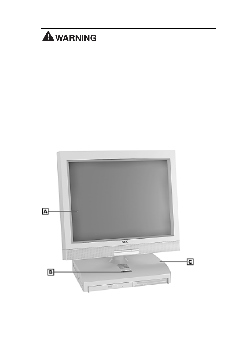
The foll o wi ng fig ures show the fea tures on the front of the system un it
and the front of the liquid crystal display (LCD) panel. Brief descriptions
of the features follow the figures.
Prolon ged or impr oper u se of a computer
PowerMate 2000 System
A
– LCD Panel
B
– Power/Sleep Button
1-2 Revi ewing System Features
C
– System Unit
Page 12
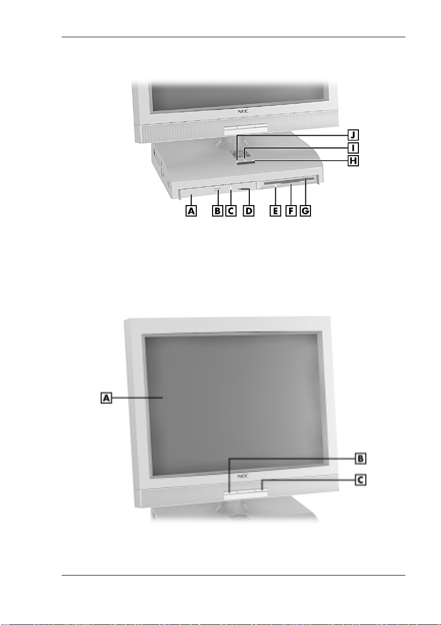
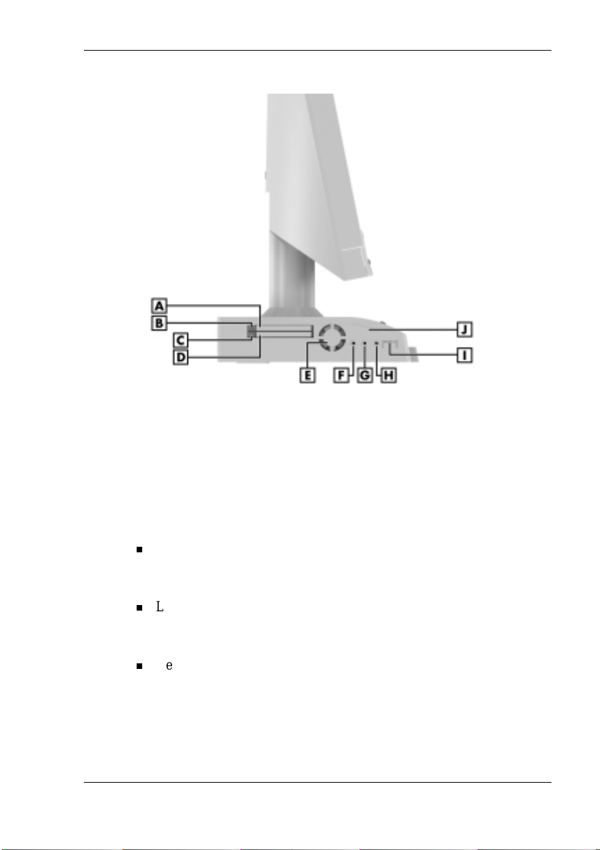
System uni t front fe atures
A
– CD-ROM Drive
B
– CD-ROM Eject Button
C
– CD-ROM Drive Lamp
D
– CD-ROM Disc Emergency Eject
E
– Diskette D r ive Lamp
LCD panel features
F
– Diskette Drive
G
– Diskette Eject Bu tton
H
– Hard Drive Lamp
I
– Power Lamp
J
– Sleep Lamp
A
– LCD Panel
B
– Decrease Brightness Level Button
C
– Increase Brightness Le vel Button
Reviewing System Features 1-3
Page 13
System Controls and Lamps
System unit controls include a power/sleep button, power lamp, sleep
lamp, and hard drive activity lamp.
Power /sleep button
To turn system unit and LCD panel power on, pr ess th e power/sle ep
button. To turn off pow er, press the butt on an d h ol d in pla ce for four
or more seconds before releasing.
Do not turn off the system power until you have
cl osed al l app lic at ions and Windo ws or y ou may possi bly l ose data.
To su s pen d s ys tem unit and LCD pa nel opera t ion, press the
power/sleep button an d r elease within three seconds or less. Thi s
places the system unit and LCD panel in a power savings mode. Use
this fea ture if you pla n to be away from your s ystem for more tha n
15 minute s.
Do not hold the button in any longer than three
seconds or you will turn off the system and possibly lose data.
Press any key or move the mouse to resume s ystem opera tion at the
point where you stopped it.
Power an d sleep lam p s
The power lamp indicates if system power is on or off. The sleep lamp
let s you know if the system is oper ating in a p ower-s aving mod e .
A stead y green power lamp indi cates that the power is on to all system
components. An am ber sleep lamp indicates tha t the system i s in sl eep
mode with full-power reduction.
Hard drive activity lamp
A flash ing green lamp indicates tha t the hard drive is acti ve and is
readin g or wri t i ng data.
Do not turn off the system unless absolutely
necessary while t he hard drive lamp is flas hing . To do so can damag e
your hard drive or data.
1-4 Revi ewing System Features
Page 14

LCD Panel
The syst em comes with an LCD panel that you can adjust up or d own and
side-to-side for a comfortable viewing position. The panel uses a 15-inch,
twisted nematic Thin Film Transistor (TFT) Super Video Graphics Array
(SVGA) color screen. The screen has a brightness of 200 candlepower
and a maximum resolution of 1024 x 768 pixels.
The LCD panel screen automatically turns on when you pr es s the system
power button. If you have an optional vid eo graphi cs arra y (VGA)
monit or attach ed to the system, the monit or can be turned on for
simultaneous viewing on the monitor and the LCD panel.
An increase brigh tness butt on and a d e c rea s e brightn ess button on the
panel allows you to increase or decrease the brightness of the display. The
buttons provide eight levels of brightness. The default brightness is
maximum.
Note
outlet changes any new brightness setting to the maximum default
brightness.
Powering off the system or unplugging the system from the power
Diskette Drive
Use the diskette drive to copy data files to and from a diskette. You can
also use it as a bo otable drive for loading a nd starting pr ograms from a
diskette.
A flashing gr e en activit y l amp on t he front of the dr ive indicates that the
drive is reading or writing data.
Press the eject button to eject a disk ette.
data, do not turn off the system or remove a diskette while the diskette
drive busy lamp is flashing.
To p reven t dama ge to the di skette drive and
Reviewing System Features 1-5
Page 15

Hard Drive
The syst em comes with either a 6.0-giga b yte (G B) or a 12-G B enh anced
intelligent device electronics (EIDE) hard drive. The drive features ultra
direct memory access ( D M A) 66 technology for fa s t data transfer.
The drive is located inside the system unit, on the right side. The drive is
not user accessible.
Hard disk activity is indicated by a flashing green lamp on the front of the
system unit.
CD-ROM Drive
All systems come with a 24X Max Slim variable speed CD-ROM drive.
Use th e CD-ROM drive to load and start progr ams from a comp act disc
(CD). You can also us e the CD-ROM dr i ve to play your audio CDs.
The CD-ROM drive operates at differ en t speeds d ep ending on wh ether
the CD you are using contain s data or music. This all ows you to get your
data faster and to see smoother animation and video.
A flashing amber activity lamp on the front of the drive indicates that the
drive i s reading data. Press the tray button to open or close the CD - ROM
tray for loading or unloading a CD. An emergency eject feature allows
you to open the tray in c ase of a power or software ma lfunc tion .
Speakers
The syst em has two 1-watt ster eo sp eakers mou n ted inside the base of the
LCD pan el. Speaker volume is control led by the volume cont r ol on the
left side of the system unit. Volume can also be controlled through the
Windows sound software.
Left Side Features
The foll o wi ng fig ure shows the fea tures on the left si d e of the system un it.
Brief descriptions of the features follow the figure.
1-6 Revi ewing System Features
Page 16
Left side features
A
– PC Card Slot 1
B
– Slot 1 Card Eject Button
C
– Slot 2 Card Eject Button
D
– PC Card Slot 2
E
– Fan
Audio Connectors
The syst em unit ha s the following audi o connector s :
Micr ophone in ja ck
Use thi s jack to connect a micr ophone for r ecording au di o information
in your data files.
Line in jack
Use thi s jack to connect a stereo a u d io device such as a ster eo
amplifier or a c assette for playback or re cordi ng.
Headphone jack
Use thi s jack to connect an opti on al headphone set. Pluggin g in the
headphone set di s ables th e bu il t-in system s p eakers .
F
– Microphone In Jack
G
– Line In Jack
H
– Headphone Jack
I
– Vol u me Co n tr ol
J
– System U nit
Reviewing System Features 1-7
Page 17

Volume Control
Use the volume control to adjust the volume of the system’s built-in
speakers or opt ional hea dphone set. Th e s p eakers are located in the base
of the LCD panel.
You can also use the Windows sound software. To bring up the Windows
volume control, double click the speaker icon on the taskbar (next to the
system cl ock). Use t he software to bal ance the sound between the left an d
right speakers.
PC Card Slots
Your system has two PC card slots that support 16-bit PC card technology
and 32-bit CardBus technology. The CardBus technology provides up to
132 MB/second of bandwidth.
The card slots support two Type II cards or one Type III PC card in the
bottom slot for extending the system’s capabilities. Each type of PC card
has a differ ent funct ion. Using the PC c ard slots, you can add a n umber of
funct ions to th e s ystem wi th a vari ety of cards (for example, modem,
memory, Small Computer System Interface).
A PC card is inserted into a PC card slot similar to inserting a diskette in a
diskette drive. Press the eject button to eject a PC card.
Removabl e s lot covers keep foreign m a tter ou t of the slots wh en PC cards
are not used.
Fan
The fan cools system unit comp onents and prevent s them from
overheatin g. Keep the area near th e fan clear for pr op er ventilation.
A feature of the fan is it s quietness. The fan operates at less t han 30 db.
Rear Features
On the rear of the syst em unit ar e the univer sal serial bus (USB) ports, DC
power connect or, mouse an d keyb oa rd ports, and other exter nal device
conn ectors. The following figure shows th e ports and connector s .
Descriptions of each follow the figure.
1-8 Revi ewing System Features
Page 18
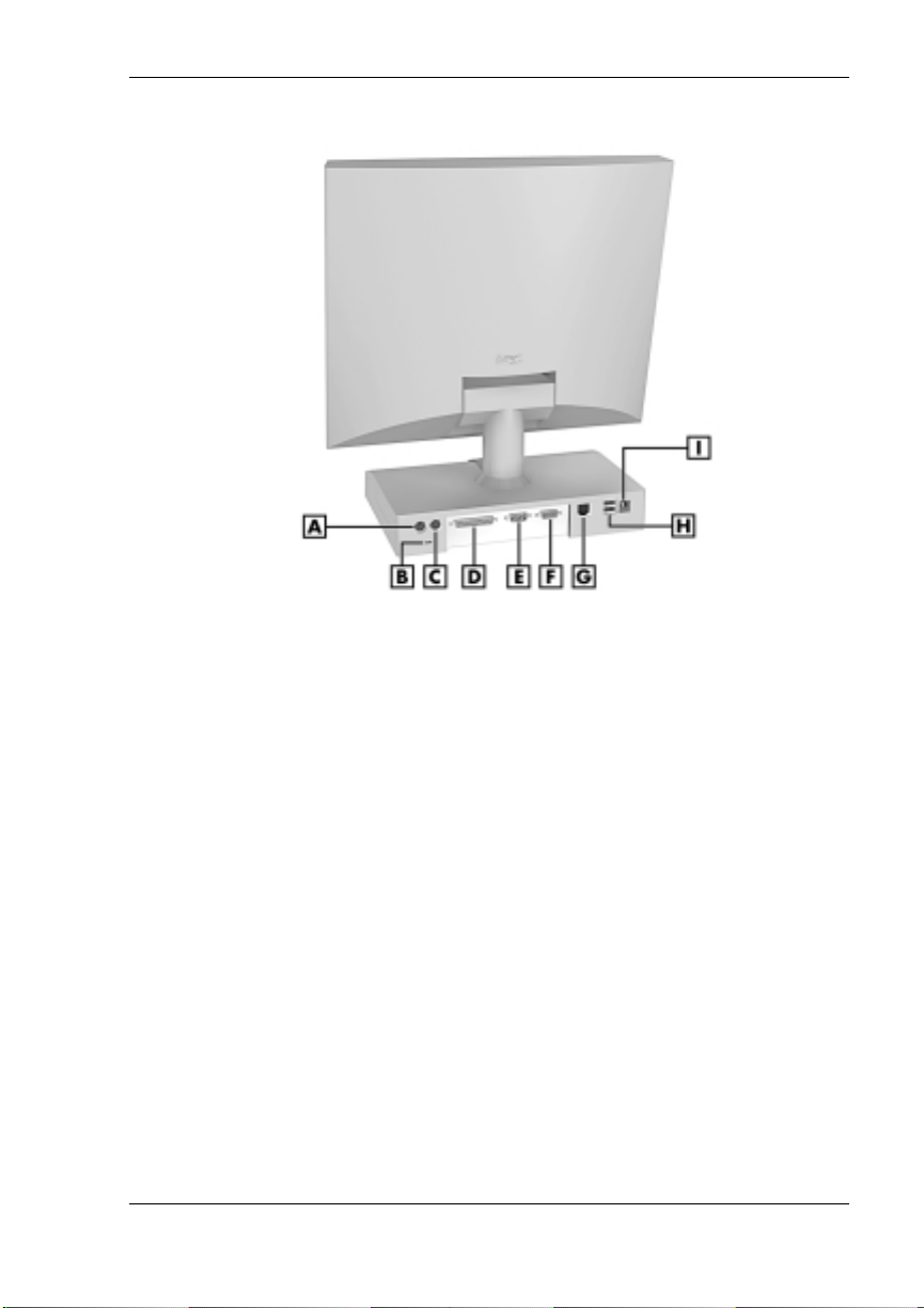
Rear features
A
– PS/2 Mouse Port
B
– Kensington Lock Slot
C
– PS/2 Keyboard Port
D
– Pri nter Por t
E
– Serial Port
Universal Serial Bus Ports
The syst em unit com es with two USB ports on the rear of the s ystem unit.
The ports allow you to easily and conveniently add plug and play USB
devices without opening up the system. You simply plug the USB device
into a por t. You c a n connect up to 127 USB de vices i ncl uding a keyboard,
mouse, monitor, printer, scanner, or speaker set.
DC Power Connector
The syst em operat es with DC power suppli ed from the AC power adapt er .
The adapter plugs into an AC p ower s ource an d the DC power connector
on th e rear of the system unit. Th e A C power adapt er u s es a s tandard
115-Vac or 230-Vac grounded power source.
F
– VGA C onn e ctor
G
– LAN Connector
H
– USB Connectors
I
– DC Power Connector
Reviewing System Features 1-9
Page 19

PS/2 Mouse Port
The system unit comes with a mouse port that supports a
®
-compatible (personal system/2-compatible) mouse with a 6-pin
PS/2
mini D I N connector .
Use this port to connect the PS/2 mouse shipped with your system.
PS/2 Keyboard Port
Your system unit com es with a ke yboard port that supports a standard
PS/2 101-key or 104-key keyboard with a 6-pin mini DIN connector.
Use t his port t o conne ct th e PS/2 keyboard shippe d with your s ystem .
VGA Monitor Connector
The syst em unit com es with a VGA conn ector on the rear of th e system
unit.
Use thi s con nector t o connect an op tional NE C M ul tiSync
VistaScan™ monitor, or other VGA- compatible monitor with a 15-pin
conn ector. You can also atta ch a projector wi th a 15-pin connect or to this
connector.
The system supports simultaneous use of the LCD panel and an optional
monit or con nected to the VGA connector.
®
monitor, NEC
Printe r Port
Use thi s p or t to connect a parallel printer with a 25-pin connector to the
system unit. The port is an enhanced capabilities port (ECP). It also
supports enhanced parallel port (EPP) bi-directional and uni-directional
protocols.
Serial Port
Atta ch a serial devi ce wi t h a 9-pin con nector to th i s s er ial port. S er ial
devices incl ud e a p ointing device, serial printer, or a modem.
1-10 Revi ewing System Features
Page 20
LAN Connector
Systems come with a local area n etwork (LAN ) . Use the RJ-4 5
compat ible LAN con nector on the rear of the system to connect a n etwork
cable to the internal 100Base-TX/10Base-T network board.
Bottom Features
A panel on t he bot tom of the system unit c overs the m e mory exp ans ion
sockets and the pa ss w ord clear jumper. (See Chapter 4, “Adding
Expansion Devices,” for information on removing the panel.)
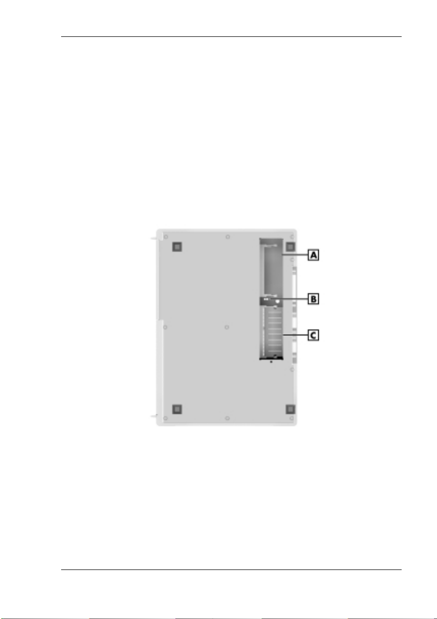
Bottom features
A
– SO-DIMM Socket 1
B
– Password Clear Jumper
C
– SO-DIMM Socket 0
Reviewing System Features 1-11
Page 21

Memory Sockets
The syst em unit com es with at lea s t one 64-MB sm all outline dual-inline
memory module (SO-DIMM) mounted in one of two memory sockets.
You can increase total system memory to a maximum of 512 MB by
using two 256-MB modules (see “Adding Memory Modules” in
Chapter 4).
The modules use synchronous dynamic random access memory
(SDRAM). Memory allocation is controlled by Dynamic Video Memory
Technology (DVMT). With DVMT, total system memory is shared
between s ystem memory and video memory. For exampl e, with 64 MB of
total system memory, 56 MB might be allocated for system memory and
8 MB for video memory, with actual memory use dependent on video
usage.
Password Clear Jumper
Use th e password cl ear jumper ( 7F4) to clear your password if you for g ot
it. To clear and reset the password, see “Jumper Settings” and “Security
Menu” in Chapter 3.
Microdesktop Chassis
The NE C Microdeskt op chassis conform s to NEC’s Very-Small Form
Factor and Flat Panel Display Specification. The microdesktop h as the
following features:
small size chassis that is 85 percent smaller and correspondingly
lighter than traditional desktops
15-inch LCD panel with 1024 x 768 pixel maximum resolution, eight
levels of d isplay brigh tness , hor i zont al viewing angl e of 60 de grees
from cen ter to r ight or left s ide of p a nel , ve rtical viewing ang le of 40
degrees from center of panel and upwards and 50 degrees from center
of panel and downwards
90-watt power supply (built into the AC power adapter).
1-12 Revi ewing System Features
Page 22

System Overview
The syst em hardware and softwa re deliver the performan ce and
technologies needed for all your ch allenging tasks today and int o the
future.
Hardware
The PowerMate 2000 Series includes the following hardware features:
PC99 Compliance
All the hardware in the system is certified by Microsoft
compliant.
Processor
The syst em comes with an Intel
front si de bus). Th e processor is a fas t , powerful processor t hat l ends
itself to computational, graphical, and networking tasks.
Audio
The system board comes with an integr ated audi o s ubsys tem. The
audio chipset gives you a surround sound system for threedimensiona l s ound effects . It also provides wavetable synthesis.
Flasha ble ROM BIOS
The system’s ROM BIOS features system setup configuration, Plug
and Play support, and flash support for economical BIOS upgrades.
®
to be PC99
®
Pentium® III processo r (100-MHz
System and Video Mem ory
Your system comes with at least 64 MB of non-ECC PC100 SDRAM
and supports up to 512 MB of total system memory. The memory uses
DVMT technology which allows system memory to be shared with
video memory. For example, with 64 MB of total system memory,
56 MB might be allocated for system memory and 8 MB might be
allocated for video memory (actual usage depends on video usage).
AGP Graphics
The syst em comes with an accelerated graphics port (AGP) in tegrated
on th e system board . AG P enhances graphics performance,
particularly for 3-D applications.
Power Management Options
Power management options extend the life of your LCD panel,
conser ve energ y, and reduce p ower costs.
Reviewing System Features 1-13
Page 23

Software
NEC provides a variety of software applications and hardware utilities
with your system to let you take advantage of your hardware capabilities.
Preloaded Microsoft Operating System
Your system comes preloaded with the Microsoft® Windows® 98 SE
operat ing syst e m or with a d ual- boot Windows NT
2000 operating system.
NEC OS Restore CD
Your system comes with an NEC OS Rest ore CD and boot able diskette.
The CD con tains th e Windows 98 operating system or the dual- boot
Windows NT/Windows 2000 operating systems, depending on your
model.
Shoul d a problem occur that ca uses data loss or corrupti on, you can
res tore your s ystem to it s original factory sta te or you c an re s tore j ust the
opera ting system and drivers. You can also perform hard drive
partitioning.
After restoring the operating s ystem, you can use the A p pl ication and
Driver CD to install your applications, drivers, and NECC online
documents.
NEC Application and Driver CD
Your system comes an NEC Application and Driver CD. Use this CD to
inst all any or al l of the software that com es wi th the s ystem, in cluding:
Microsoft® Interne t Expl orer Browser
Internet Explorer provides a top-notch browser with preloaded links
for ea sy access to th e wor ld wide web. Also use Internet Ex p lorer to
acces s one of the ma ny new browse r-based utiliti e s .
®
4.0 and Windows
®
Norton AntiVirus™ 2000 Software
Protect the system from virus es by run nin g Nort on’s virus scan
software.
1-14 Revi ewing System Features
Page 24

Adobe® Acr obat® Reade r
Use th e Adob e Acrobat Rea d er to read an d print por table document
format (PDF) files found on the Internet and PDF documents included
with various software applications.
Intel LANDesk® Client Manager
Use LANDesk software to track system information such as serial
number, BIOS version, memory capacity, disk capacity, expansion
board setting s, and applications. Use LANDesk software for remote
star ts from a server comput er using Wake- On LAN and remot e r ebo ot .
NEC INFO Center
The NEC INFO Center an online version of this user’s guide, an d
Tour, Questions, Solutions, and Services modules.
Select the Tour module to look at the documentation, tools, and
services that come with th e system. Th e Q u es tions modu le includ es
answers to frequently asked questions. Use the solutions module to
find possible solutions to system problems. The Services module
conta ins servi ce inform ation such as where to go on th e Intern et for
help, who to call for service, and more.
A wide selection of drivers
Drivers for hardware that is compatible with PowerMate series
comput ers are pr ovi d ed wi th the or iginal man u facturer ’s installa tion
wizar d s to ensure correct installa tion.
Security
The system has hard wa re, software, and mechanical security features th at
offer pr otect ion a gain s t unaut horized acc e s s to your s ys tem and da t a. The
follo wing security featu res are a va ilable with the system.
Password security
The BIOS Setup utility includes a feature that lets you set a user or
supe rvisor password, or both.
The user password control s booting of the system an d controls acces s
to the Setup util ity and th e keyboa rd. (User access t o the BIOS Setu p
utility is limited to a subset of all BIOS Setup parameters when a
supervisor password has been set.)
The sup ervisor pa s sw ord all ows full access to the syst em and the
BIOS.
Reviewing System Features 1-15
Page 25

Security Lock Slot
The security lock slot on the rear of th e system accept s a Kensin gton
Security Stan d ar d connect or or other locking devi ce. Secur e the
locking device to the security lock slot and to an immovable object to
pr otect your s ystem from theft .
Hard Drive Security
Your system supports password protection for the hard drive. Hard
drive password protect ion restricts access to the dr ive if the drive is
removed and installed in an other sys tem. The s ystem does not prompt
for hard drive passwords while th e drive remains in the current
system.
The pa s s wor d s are written to the system BI OS and to th e hard drive t o
ensure that the password protection travel s wi th the hard drive in the
event it is moved to an ot her system . (See “Hard Drive Security” in
Chap ter 3 for addi tional in formation on using this feature.)
Wind ows network s ecu rity features
To learn more about the network security features available through
the Windows oper ating system , refer to your Windows docum entati on
or consu lt your system ad m i nistrat or.
®
1-16 Revi ewing System Features
Page 26

Setting Up the System
Cable Connections
Startup
Shutdown
Power-Savi ng Op era tion
Syste m Care
More Informatio n
2
Page 27

This cha pter provid e s basic informa t ion for set tin g up and us i ng your
system ( refer t o th e Quick Setup poster for details) . Includ ed ar e cable
conn ections, s ystem star tup procedures, system shutdown procedu res, and
system ca re. The chapter also includ es a table showing where t o find
additional information about your system.
Cable Connections
After unpacking the system (save the carton) and positioning the system
in your work area, con nect the system components using the Quick Setup
poster and the following tips.
Use the icons on the rear and side of the system unit to identif y th e
USB, keyboard, mouse, LAN, printer, monitor, power, and audio
connectors.
See your n e twork adm inist rat or for gu ideline s on configuring the
LAN.
Connect the system A C ad apter power cord to a surg e protector
(recom mended ) or a properly ground ed wall outlet and to th e DC
power connect or at the rear of the system unit.
NECC recommends connect ing t he AC ad apter
power co r d to a su rge pr otec tor t o protect y our sy s tem.
Startup
Press the power button to turn on the system unit and LCD panel. The
power l amp lights green to indicate that the system is on. The system
performs its Power-On Self-Test (POST) and several messages appear on
the screen indicatin g that the system is check ing its su bsystems.
Note
appears:
Setu p Uti lity, immediately press
Chapter 3, “Configuring the System,” for information on using the BIOS
Setup.)
After a short delay, Win d ows st arts up.
2-2 Setting Up the System
At t he bottom of the NEC startup s creen, th e f ollowin g mess age
Press F2 to enter BIOS Setup
F2
. If you want to enter the BIOS
whil e the start up scr een di spla ys. (See
Page 28
If a proble m occurs, a s eries of beep s might sound. I f t his h appen s
repeatedly after powering on, power off the system and go to Chapter 5,
“Solving Syst em Problems.” T he chapter provi des help ful hints for
solving system problems.
If the system displays a messag e indi cating that system settings have
changed, run the BIOS Setup Utility (see Chapter 3, “Configuring the
System”).
On system s loaded with the Wind ows N T
opera ting system , press
The log- on box appears for ent ering a password.
Shutdown
Follow t hese step s to power off the system.
a sy stem i n sleep mode, save and cl ose any open applicat i ons, exit
Windows, and power down the system.
1.
If the system is in sleep mode (sleep mode lamp amber), move the
mouse or press a key to ta k e it out of sleep mode (see “Power Saving
Operation” in the next section).
®
4.0 or Windows 2000
Ctrl Alt Del
To p reven t damage to system components, wak e
when prompted on-screen to do so.
2.
Save and e xit all your open appli c ations.
3.
Make sure that the hard drive, disk ette drive, and any oth er d rives are
not in us e. A lit device l amp indi cates that the device i s in use.
Wait until all open applications are saved and
cl osed befor e usin g the Windo w s shut down procedur e i n step 4.
Unless absolutely necessary, never power off the system if the system
sl eep lamp is amber , i f either the hard drive lamp, d iskette drive, or other
device lamp is flashing, or if any applications are open. Information on the
device might be lost or damaged.
Setting Up the System 2-3
Page 29

4.
Start
Click
the computer
on the taskbar and click
, then click
Yes
or pr e s s
dependi ng on you r ope rating system.
If the system is configured with Windows 98 or Windows 2000,
the syst em shut s down automatically aft er a shor t interval.
If th e s ystem is confi g ured with Windows NT, and after you
perform a Windows shut down, power off the system by pressing
and holding in the power button for four seconds or longer
before releasing.
Power-Saving Operation
If the system is running Windows 98 or Windows 2000, you can put it in
sleep mode (a power-saving state) by pressing and immediately releasing
the power butt on on th e front of th e system unit. The sleep mod e is a
convenient way of conservi ng ener g y when you are g oing to be awa y
from your system for more than 15 minutes.
Tak e car e t o pres s and immediately release the
power bu t ton to enter the sleep mode. Avoid pressi ng and holding i n the
power button longer than three seconds or you may turn off power and
possibly lose data from any open applications.
Shut Down
Enter
for shut down,
. Select
Shut down
The syst em also goes into sl eep mode when it has been inact ive, if the
power management has been enabled in BIOS, and an inactivity timeout
has been enabled. (See Chapter 3, “Config uring Your S ys tem,” for
information on setting power management functions.)
When the system goes into sleep mode, it automatically saves data and
system statu s and then shu ts off power to all possible compon ents. Sleep
mode lets you save power without firs t s avin g your work.
An amber s leep lamp in di cates that the system is in sleep m od e. Press a
key or move the mouse to resume system operation where you left off.
2-4 Setting Up the System
Page 30

System Care
The system is a durable system built for dependable use. With protective
mea s ures a nd pr oper care, you can prevent problems and promote the
successful operation and long life span of the system.
Protecting Your System From Damage
There are several ways tha t you can prot ect the system from p ossible
damage. NECC strongly recommends the following protective measures.
Connect a surge s u ppressor bet w een the system and a grou nded wall
outlet. A surge suppressor protects the system from sudden transient
increases and decreases in electr ical power.
Be sure t o connect al l p eripher als, such as a printer , to the surge
suppressor. The surge protector should be the only device that you
plug into the wall outlet.
Avoid r ep eated power -on cycles. These subject the system
components to temperature variations and stress.
Discon nect the s ystem from telephon e an d power lines when an
electrical storm thr eatens. If you h ave a fax/modem, lightnin g can
travel in on the phone line and damag e both the fax/mod em an d the
system u n it. Ligh tn ing can also travel in on power lines and dam age
the LCD panel and system unit.
Be sure th at system p ower is off bef ore connectin g or d isconnecting a
cable (US B devices d o not require poweri n g down the system when
conn ecting). Never make ca bl e ch anges wh en the system power is on.
Doing so can damag e the system and its per ipherals.
Use BIOS Setup Utility options to protect against viruses (see
Chapter 3). You shou ld al so use the Norton vi rus sc an protection
software pr ovided with the syste m to p rote c t th e system from vi rus es.
If you plan to use software programs ot her th a n NEC C-su ppli e d
softwa re, NECC strongly r ecom mends that you take the necessary
steps, such as vir us checks, to protect th e s ystem .
Position the system away from direct sunlight and extreme hot and
cold temperatures.
The recom mended op er ating environm en t is from 50°F to 95°F (10°C
to 35°C).
Setting Up the System 2-5
Page 31

The recom mended non-opera ting environment (shippin g or storage) is
from 14°F to 158°F (-10°C to 70°C).
After turning off power, wait about five seconds for the hard drive to
spin down before you p ower on aga i n.
Be sure th at nothing is placed on top of th e system AC ada pt er power
cord.
Keeping Your System in Good Condition
Maintain the condition of your system by periodically using the following
procedures.
For safety, power off and unplug your system
and any external devices before cleaning them.
Preven t dust from en tering th e system by covering it when not in us e.
Clean the outside of the system u n it and LCD panel (but not the
screen) with a soft clean cl ot h.
Remove stubborn s tains with a cloth sli gh tly damp ened with a mild
detergent. N ever use a strong clean er or s ol vent on any part of the
system.
Clean the LCD panel screen with a soft, lin t-free cl ot h or a screen
wipe desi g ned for that purp ose. Specia l screen wip es are available
through your local computer dealer.
Keep food and liqu ids away from the system.
Peri odically clea n th e keyboa rd with a va cuum cleaner bru sh
atta ch ment. Do not use any liq ui d cleaner s on th e k eyb oa rd as they
can damage the keyboard.
If an object , such a s a pap er clip, falls into the k eyb oa rd, turn the
keyboard over and g entl y shake it.
2-6 Setting Up the System
Page 32

Moving or Shipping Your System
Use th es e s teps to pr epare the system for moving or shi p ping.
1.
Back up your files on the hard drive to diskettes, server hard drive, or
other backup devices.
Take precautions for st or ing and transporting storage media so that
they are not exposed to magnetic fiel d s or electri cal impuls es .
2.
Remove any dis kette from the di sket te dri ve . If you have a CD in the
drive, remove the CD.
3.
Remove a ny PC cards from the car d slots on th e left side of your
system u n it. In stall the slot cov ers.
4.
Wake up a s ystem in sleep m od e, save and close any open
appli cations , shut down Windows, an d turn off the s ystem unit an d
any external options connected t o it .
5.
Unplug the system A C adapter p ower cord from the wal l ou t let or
surge suppressor and the A C a dapter fr om th e s ystem unit.
6.
Unplug any exte rnal options from the wall outl ets or s urge
suppressor, then disconnect them from the system unit.
7.
Pack the system comp onent s in the origin al shipping materials and
cartons. If th es e are not ava ilable, be sure to use ad eq uate packing
materials to protect the components.
Note
event that you need to ship the system back for repair.
Be sure to save the original shipping materials in the unlikely
To set up the system, fol l ow the steps on the PowerMate 2000 Series
Quick Setup poster that comes with the system.
Setting Up the System 2-7
Page 33

More Information
Once the system is up and running, we suggest that you do the following.
Install applications provided by NECC on the NEC Application and
Driver CD.
See “Setting Up a He al t hy Work E nvironment” in Appendix A.
Install any of your own applications. See the documentation that
comes with the application.
See the following quick reference table to find information about using
your system.
Quick Reference to Information About Your System
Information Where to Find It
Accessing the world wide web Chapter 6
Adding expansion devices Chapter 4
Gui delines for using yo ur computer Appendi x A
Installing the applications provided by
NECC
Installing the NEC INFO Center online
documentation
Pro tecting the system from vi ruses Chapter 1
Setting a password Chapter 3
System specifications Appendix B
Taking care of the system “System Care” in Chapter 2
Troubleshooting tips Chapter 5
Uninstalling the NEC INFO Center “Uninstalling the NEC INFO Center” in
Using support services Chapter 6
“In stall ing A pplications” in Chapter 3
“Installing the NEC IN F O Center” in
Chapter 3
Chapter 3
2-8 Setting Up the System
Page 34

Configuring the System
Configuration Tools and Utilities
BIOS Setup Utility
Hard Drive Security
FLASH Utility
NEC Application and Driver CD
NEC INFO Center
NEC OS Restore CD
System Board Jumper Settings
Intel Processor Serial Number Control Utility
3
Page 35

This cha pter provid e s informa t ion on con figuri ng your syste m. The
chapter includes:
Phoenix® Technologies Ltd. BIOS Setup utility for configuring your
system
FLASH Utility for BIOS updates
NEC Applications and Driver CD for installing the NECC-supplied
applications and optional drivers
NEC IN FO Center for qu ick access to i nforma tion about your system
NEC OS Restore CD for restor in g th e op erating system
jumper s ettings for clear ing your pa s s wor d , shoul d you forget it
Intel Processor Serial Number Control Utility for controlling the
readin g of the processor s erial numbe r.
See th e followin g ta bl e for a qui ck guide to the ut ilities, tools, or
procedures required for configuring the system. For detailed information
about these and other tools, s ee the secti ons follo wi ng the ta ble.
Configuration Tools and Utilities
The foll o wi ng tabl e lists ways you ca n confi gure the system, an d the
utility, tool, or procedure to use for the configuration.
Configuration Tools and Utilities
Configuration Method, Tool, or Utility
BIOS, updating FLASH Utility
Boot devices, determining BIOS Setup (Boot Menu)
Boot order, changing BIOS Setup (Boot Menu)
Clearing password Jumper Settings
Diskette drive, enabling BIOS Setup (Main Menu)
Drivers for NECC hardware NEC Application and Driver CD
3-2 Configuring the System
Page 36

Configuration Tools and Utilities
Configuration Method, Tool, or Utility
Hard drive, reformatting NEC OS Restore CD
Hard drive, repartitioning NEC OS Restore CD
Har d drive, setti ng a pr e-delay BIOS Set up (Power M enu)
Inactivity timeout, setting BIOS Setup (Power Menu)
Keyboard options BIOS Setup (Main Menu)
Memory, checking BIOS Setup (Main Menu)
NEC INFO Center, installing NEC Application and Driv er CD (see
“Installing th e NEC IN F O Cente r ”)
NEC INFO Center, uninst all ing “Uninst allin g the NEC INFO Center”
Operating system, restoring NEC OS Restore CD
Parallel port, enabling, configuring BIOS Setup (Advanced Menu)
Pas sword, setting or clearing (user ,
supervisor, or both)
Plug and Play, enabling BIOS Setup (Advanced Menu)
Power management, enabling,
configuring
Serial ports, enabling BIOS Setup (Advanced Menu)
SO-DIMM memory, checking BIOS Setup (Main Menu)
Software pr ovided throug h NECC,
installing
Sound, enabling BIOS Setup (Advanced Menu)
Time and date, setting BIOS Setup (Main Menu)
USB functions BIOS Setup (Advanced Menu)
Windows 98, Windows 2000 (when
available), or Windows NT, restoring
BIOS Setup (Security Menu)
Jumper settings
BIOS Setup (Power Menu)
NEC A pplication and Driver C D
NEC OS Restore CD
Config ur in g t he Sy stem 3-3
Page 37

BIOS Setup Utility
The BIOS Setup Utility lets you configure the main components of your
system. The utility is r es ident in the system FLAS H memor y and does not
requ ire a diskette or an oper ating system p resent to run .
Your system shi p s from the fact ory with th e correct system parameters for
your c onfigurati on. Unless you add opti onal h a rdware, you do not need t o
run the BIOS Setup Utility to operate your system. However, you might
wish to run the BIOS Setup Utility to set features that customize your
system, such a s security feat ures.
NECC recommends that you print out or write down your current BIOS
Setup parameters and store the information in a safe place. This lets you
rest ore your system to the current par ameter s i f you need to have the
CMOS battery replaced.
How to Start Setup
To start the BIOS Setup Utility, follow these steps.
1.
Turn on or reboot the system .
2.
Note
6.0-GB hard dr ive. The actu al set t ings on the Main Menu and Adv anced
Menu screens depend upon the hardware installed in your system.
F2
Press
scr e en). Y ou ha ve about five se c onds to pre s s
Setup’s Main Menu win d ow ap pears similar to th e fol lowin g s cr een.
at the NE C startup scr een (
The followi ng scr een is a typical s creen for a syst em with a
3-4 Configuring the System
F2
appears on the bottom of the
F2
.
Page 38

Setup Main Menu
PhoenixBIOS Setup Utility
Main Advanced Security Power Boot Ext
Item Specific Help
System Time: [10:34:50]
System Date: [01/19/2000]
Select the display
Language [English (US)] language for the BIOS.
Legacy Diskette A: [1.44/1.25 MB 3 1/2"]
Primary Master [6007MB]
Primary Slave [None]
Secondary Master [CD-ROM]
Secondary Slave [None]
Keyboard Features
Boot-Time Diagnostic Screen: [Disabled]
System Memory: 640 KB
Extended Memory: 63488 KB
BIOS Revision: 138A0200
Processor Serial Number: [Disabled]
F1 Help
ESC Exit
F9 Setup Defaults
F10 Previous Values
–/+ Change Values
Enter Select Sub-Menu
| | Select Item
— Select Item
How to Use Setup
The Setup utility has a Main Menu window and six top-level menus with
submen us (see th e abo ve figur e). The menu bar at the top of the Main
Menu window lists the following top-level menus.
Main Use the Main M en u for basi c s ystem configurat ion. For
examp le, select M ain to set the system dat e, set dis k ette and har d disk
parameters, check memory parameters, or set the processor serial
number feature.
Advanced Use the Ad vanced Menu to set the system for Plug and
Play, PC I configuration, serial p ort and printer port addresses and
interrupts, memory cache configurations, I/O device configuration,
DMI event logging, and more.
Security Use this menu to set User and Supervisor Passwords,
security mode, pa s sword on boot, network boot, viru s check, and
more.
Power — Use the Power Menu to set power management parameters
such as power savings, auto suspend timeout, hard disk timeout, and
system switch.
Config ur in g t he Sy stem 3-5
Page 39

Boot — Use thi s menu t o s e t boot options, including restore on
ac/ power loss , set bo ot sequen ce , an d a s sign drive letters t o remova ble
devices.
Exit Exits the Setup Utility with various save or discard options.
Use the keys listed in the legend bar on the bottom of the Setup Menu to
make the selections or exit the current menu. The following table
describes the legend keys.
Setup Key Functions
Key Function
F1 Prov id es help for the parameter field
being displayed.
Esc Exits th e menu .
Up or down arrow keys Moves cursor up and down for item
selection.
Left or right arrow keys Selects next menu.
-/+ keys Changes values.
Enter Executes a command or selects
submenu.
F9 Loads th e defa ult confi guration values
F10 Saves the current v alues and exi ts
To select one of the six menus fr om the menu bar, u s e th e left and ri ght
arrow ke ys. Use the up or down arrow keys to sele ct an it em under the
menu.
Menu items preceded b y a > contain a submenu of selectable fi elds for
setting system parameters. Display a submenu by using the up or down
arrow keys to move the cursor to the desired submenu, then press
An Item S p ecific Help window on the right side of each menu displa ys
the help text for the curr en tly selected Setup opt ion. It updates as the
cursor moves to each new field.
3-6 Configuring the System
for the current menu.
Setup.
Enter
.
Page 40

Pressing F1 on any menu brings up the General Help window that
describes the legend keys and their functions.
Esc
Press
to exit th e current wind ow.
The following subsections describe the six top level menus and their
submenus.
Main Menu
Ch oos e the Main Menu by selectin g M a in in the leg e nd bar on the M a in
Menu s cr een . Other Main Menu opt ions are ava ilable b y select ing
submenus.
Use th e arrow keys to select one of the Main Men u op tions and pr ess
Enter
to select a submenu. I t ems with gra yed-out tex t are not ava ilable.
Explan ations of each Main Men u item are in the following tabl e.
Setting items on this menu to incorrect values
can cause your syste m to malfunction.
Main Menu Item s
Menu Item Settings (default is bold)
System Time Set system time in this field. Press
Enter
to move between hour, minute, and
second fields.
Example: 09:30:50
System Date Set system date in this field. Press
Enter
to move between month, date, and
year fields.
Example:
04/18/2000
Language
English
Selects the display language for the BIOS.
(US), Japanese
Config ur in g t he Sy stem 3-7
Tab
Tab
or
or
Page 41

Main Menu Item s
Menu Item Settings (default is bold)
Legacy Diskette A Disabled
360 KB 5 1/4”
1.2 MB 5 1/4”
720 KB 3 1/2”
1.44/1.25 MB 3 1/2”
2.88 MB 3 1/2”
Selects the disk et te drive type.
Primary IDE Master
Primary IDE Slave
Secondary IDE Master
Secondary IDE Slave
6007 MB
None
CD-ROM
None
Note: The following setting information
applies to the primary and secondary master
and slave devices.
Each device menu item displays the hard
dri ve or C D -ROM identifier if a device is
installed.
If you install a hard drive th at does not featu re
auto IDE type detection or your IDE hard
drive was formatted on another system with
parameters diff erent from those reported by
the drive, en ter a parameter for each of the
fields in the device submenu.
Bring u p a devi ce submenu by pres sing
Enter
. The submenus i nclude Ty pe, CHS
Format, and LBA Format. E ach s ubmenu and
its fields are described next.
3-8 Configuring the System
Page 42

Main Menu Item s
Menu Item Settings (default is bold)
Type User,
Cylinders When Type is Auto, value in the Cylinders
Auto,
None, CD-ROM, IDE/ATAPI
Removable
When set to Auto, the values for Cylinders,
Heads, Sectors, Total Sectors, and Maximum
Capacity are dis play ed but a re read onl y.
When set to Auto, the BIOS detects what the
dri ve is capable of, not the trans lation
mechani sm that was used t o format the drive.
If a drive is run in a mode other than the
mode in which it was partitioned and
formatted, unpredictable results might occur,
including data loss.
When set to None, informs the system to
ignore this drive.
When set to CD-ROM or IDE/ATAPI
Rem ovable, allo ws the manua l entr y of al l
fields described next.
When set to User, allows t he ma nual en try of
all fields d escribed next.
CHS Format (label field only)
field is aut o-detect ed and f ield is r ead onl y.
Heads When Type i s Aut o, value in H eads f ield is
auto-detected and field is read only.
Sector s When Ty pe is Au to, value in Sectors field is
auto-detected and field is read only.
Maximum Capacity 6007 MB
LBA Format (l abel field onl y)
Total Sectors 11733120 total sectors
Maximum Capacity 6007 MB
Config ur in g t he Sy stem 3-9
Page 43

Main Menu Item s
Menu Item Settings (default is bold)
Mul ti-Sector Transfers D isabled, 2, 4, 8, 16 sectors
Determines t he num ber of sectors p er block
for multi-sector transfers.
When Typ e is Auto, value in Mult i-Sect or
Transfers fiel d i s auto -detect ed and f ield is
read only.
LBA Mode Control
32-Bit I/O
Transfer Mode Standard, Fast PIO1, Fast PIO2, Fast PIO3,
Ultra DMA Mode Disabled, Mode 0, Mode 1, Mode 2, Mode 3,
Enabled
When Ena bled is select ed, it c auses logical
block addres sing t o be used in place of
cylinders, heads, and sectors.
When Typ e is se t to Auto, the value in the
LBA Mode field is auto-detected and the field
is read only.
Disabled
When Enabled, allows 32 bit data transfers.
Fast PIO4, Fast PIO3/DMA1, Fast
PIO4/DMA2
Selects the method for moving data to and
from the drive.
When Typ e is se t to Auto, the value in the
field is aut o-detect ed and the field is read
only.
Mode 4
Selects the Ultra DMA Mode for moving data
to and from the drive. Autotype the drive to
select the optimum transfer mode.
, Di sabl ed
, Enabled
3-10 Configuring the System
When Typ e is se t to Auto, the value in the
field is aut o-detect ed and the field is read
only.
Page 44

Main Menu Item s
Menu Item Settings (default is bold)
Keyboard Features Press
Numlock Auto, On,
Key Click
Keyboard auto-repeat rate
Keyboard auto-repeat delay 1/4 sec,
Legacy USB Support Disabled,
Boo t-Ti me Di agnostic s Screen
System Memory Displays amount of conventional memory
Enter
to check or change keyboard
parameters.
Off
Selects the power-on state for Numlock.
Disabled
Enables or disables key click.
30/sec
13.3/sec, 10/sec, 6/sec, 2/sec
Selects key repeat rate.
Selects delay before key repeat.
Disables or enables legacy USB support.
Disabled
Selecting Enabled displays the diagnostic
screen during boot.
detected during boot.
, Enabled
, 26.7/sec, 21.8/sec, 18.5/sec,
1/2 sec
, 3/4 sec, 1 sec
Enabled
, Enabled
This field is read-only and cannot be changed
from BIOS Setu p .
Exampl e: 640 KB
Configuring the System 3-11
Page 45

Main Menu Item s
Menu Item Settings (default is bold)
Extended Mem ory Dis play s amou nt of ext ended mem ory
detected dur ing b oot.
This field is read-only and cannot be changed
from BIOS Setu p .
Exampl e: 634 88 KB
BIOS Revision Displays the BIOS revision number.
This field is read-only and cannot be changed
from the BIOS Setup.
Example: 138A0200
Processor Serial Number
Advanced Menu
Choose t he Advan ced Menu by selectin g Ad vanced in the legend bar on
the Main Menu scr een . O ther Advanced Menu options are available by
selecting submenus.
Use th e arrow keys to sele ct one of the Advanced Menu opt ions and press
Enter
to select a submenu. I t ems with gra yed-out tex t are not ava ilable.
Explan ations of each Advanced Menu item are in th e fol lowing table.
can cause your syste m to malfunction.
Disabled
Controls detection of the processor serial
number.
Setting items on this menu to incorrect values
, Enabled
3-12 Configuring the System
Page 46

Advanced Menu
Menu Item Settings (default is bold)
Plug and Play OS No,
Reset Configur ation Data
PCI Configuration Press
PCI IRQ Line 1
PCI IRQ Line 2
PCI IRQ Line 3
PCI IRQ Line 4
Cache Memory Press
Memory C ach e Disabled,
Yes
Select Yes if you are booting a Plug and
Play capable operating system.
Select No if you want the BIOS to configure
non-boot devices.
No
, Yes
Select Yes if you want to clear the Extended
Sys tem Co nfi guration Data (ESCD ) area.
submenus.
Disabled,
12, 14, 15
Use Auto Selec t if there are no ISA or EISA
devices installed on the system.
Select an IRQ (3-15) if installing a PCI
device requiring an IRQ and if the IRQ is not
already in use by ISA or EISA devices.
submenus.
Enter
to access the following
Auto Select
Enter
to access the following
Enabled
, 3, 4, 5, 7, 9, 10, 11,
Sets the state of the memo ry cache.
Cache System BIOS Area Uncached,
Controls caching of system BIOS area.
Cache Video BIOS Area Uncached,
Controls caching of system video BIOS
area.
Write Protect
Write Protect
Configuring the System 3-13
Page 47

Advanced Menu
Menu Item Settings (default is bold)
Cac he Bas e 0-5 12K Unc ached, Wri te Th roug h, Write Pr otec t ,
Write Back
Controls caching of 512K base memory.
Cac he Bas e 512-640 K Unc ached, Wri te Th roug h, Write Pr otec t ,
Write Back
Controls caching of 512K-640K base
memory.
Cache Extended Memory
Area
Cache C800-CBFF
Cache CC00-CFFF
Cache D000-D3FF
Cache D400-D7FF
Cache D800-DBFF
Cache DC00-DFFF
Uncached, Write Through, Write Protect,
Write Back
Controls caching of system memory above
one MB.
Disabled
Write Back
Settin g at Disabl ed prohibits ca chin g.
Setting at Write Through permits writes to be
cached and sent to main memory at once.
Setting at Write Protect c auses t he BIOS to
ignore writes.
Setting at Write Back permits write caching
but delays sending data to main memory
until necessary.
, Wri te Throug h, Write Pr otect,
3-14 Configuring the System
Page 48

Advanced Menu
Menu Item Settings (default is bold)
I/O Device Configuration Press
submenus.
Serial Port A Disabled,
Setting at Enabled allows the user to
con fig ure the port .
Setting at Auto enables the BIOS or
operating system t o conf igure th e port.
Base I/O Address
Interrupt IRQ3,
Parallel Po r t Disabl ed,
Mode Output Only,
3F8
, 2F8, 3E8, 2E8
Selects the base I/O address for serial
port A.
Selects the IRQ for serial port A.
Setting at Enabled allows the user to
con fig ure the port .
Setting at Auto enables the BIOS or
operating system t o conf igure th e port.
Enter
to access the following
Enabled
IRQ4
Enabled
, Auto
, Auto
Bi-directional
, ECP
Selects parallel port mode.
Base I/O Address
Interrupt IRQ5,
378
, 278, 3BC
Selects the base I/O address for the LPT
port.
Selects the IRQ for the LPT port.
IRQ7
Configuring the System 3-15
Page 49

Advanced Menu
Menu Item Settings (default is bold)
Floppy Disk Controll er Disabled,
Setting at Enabled allows the user to
con fig ure the controller.
Setting at Auto enables the BIOS or
operating sy stem t o conf igure the controller.
Base I/O Address
Large Disk Access Mode Other,
Local Bus IDE Adapter Disabled, Primary, Secondary,
QuickBoot Mode
Primary
Sets the base I/O address for the controller.
Select DOS if using DOS operating system.
Select Other if using another operating
system such as UNIX or Novell NetWare.
Enables the integrated local bus IDE
adapter.
Disabled
When Enabled, the BIOS does not test
system memory above 1 MB or wait for
ready signals, allowing a quick boot.
Enabled
, Secondary
DOS
, Enabled
, Auto
Both
Sound
DMI Event Logging Press
Event Log Capacity Status only.
Event Log Validity Status only.
View DMI E vent L og Status on l y, press
Enabled
Select Disabled to turn off onboard sound.
Enter
submenus.
3-16 Configuring the System
, Di sabl ed
to access the following
Enter
to view.
Page 50

Advanced Menu
Menu Item Settings (default is bold)
Clear All DMI Event Logs
Event Logging
Mark DMI Events As Read Press
LANDesk ® Service Disabled,
Preboot Management
No
, Yes
Selecting N o preven ts clear ing o ut the
DIMM event lo gs.
Enabled
Selecting Enabled permits logging of DMI
events.
Events as read?”
Select Enabled to enable the onboard
LANDesk.
Disabled
Select E nabled to enable th e Prebo ot
Management function.
Security Menu
Choose the Security Menu by selecting Security in the legend bar on the
Main Menu screen . Other Secur ity Menu opt ions are ava ilable by
selecting submenus.
, Di sabl ed
Enter
Enabled
, Enabled
. Select
Yes
or No to “Mark all
Use th e arrow keys to sele ct one of the Securi ty Menu options and pres s
Enter
to select a submenu. I t ems with gra yed-out tex t are not ava ilable.
Explanations of each Security Menu item are in the following table.
Configuring the System 3-17
Page 51

Security M en u It ems
Menu Item Settings (default is bold)
Sup ervisor Passw ord Is
User Pas sword Is
Set Supervisor Password Press
Set User Password Press
Clear
Status only, user c annot modify. S uper visor
password controls access to the BIOS Setup
Utility.
Clear
Status only, user c annot modify. U ser
password controls access to the system at
boot.
Use this field to set or change the supervisor
password. Press
box where the password can be entered and
confirmed.
Use this field to set or change the user
password. Press
box where the password can be entered and
confirmed.
, Set
, Set
Enter
Enter
to access.
Enter
to access.
Enter
to bring up a dialog
to bring up a dialog
3-18 Configuring the System
Page 52

Security M en u It ems
Menu Item Settings (default is bold)
Security Mode Press
Use thi s mo d e to se lect
SmartCard, or Finger Print. Press
open the s elected field.
Use the Smart Card field to as sign a ccess to
the Smar tCard Read er by t he supervisor
and /or user. Press
Sma rtCard Rea der dialo g box f or sett ing u p
SmartCard security.
The Assign Su pervisor SmartCar d f iel d
controls Supervisor access to the BIOS
Setup utility and the system. A PIN number
controls access.
The Assign Us er SmartCa rd fi eld co ntrols
user access to the system at boot. A PIN
number controls access .
Password on Boot
Fixed Disk Boot Sector
Disabled
When Ena bled, requ ires password entry
before boot. System remains in secure
mode unt i l password is en tered.
Normal
Enter
to access the Security Mode.
Password
Enter
to bring up the
, Enabled
, Write Protect
(default),
Enter
to
Diskette Access
Write Pr otec t protects the b oot secto r on th e
hard disk from viruses.
Supervisor
Controls access to the diskette drive.
, User
Configuring the System 3-19
Page 53

Security M en u It ems
Menu Item Settings (default is bold)
Network Boot Setting Press
Keyboard/Mouse Lock Disabled,
Select Enabled to lock the keyboard and
mouse wh en remote b ooting.
Virus Check Reminder
System Backup Reminder
Disabled
Displa ys remind er message at bootup.
Message is dai ly, every Monday, o r first of
every month.
Disabled
Displa ys remind er message at bootup.
Message is dai ly, every Monday, o r first of
every month.
Power Menu
Choose t he Power Menu by select ing Power in the legend bar on the Main
Menu s cr een. Other Power Menu options are availabl e b y selecting
submenus.
Use th e arrow keys to select one of the Power Menu opti ons and press
Enter
to select a submenu. I t ems with gra yed-out tex t are not ava ilable.
Explan ations of ea ch Power Menu item are in the followi ng tabl e.
Enter
to access.
Enabled
, Daily, W eekly, Mo nt h ly
, Daily, W eekly, Mo nt h ly
Note
Windows 98 or Windows 2000.
Power manag emen t is only su p p orted in systems run n ing
3-20 Configuring the System
Page 54

Power Menu Settings
Menu Item Settings (default is bold)
Power Savings Disabled,
Savings, Maximum Performance
Disabl ed set t ing turn s off Po wer
Management.
Maximum Power Savings setting conserves
the grea test amou nt of power.
Maximum Performance setting conserves
power but allows best system performance.
Cus tomized s etting allows the us er to m odify
the Auto Suspend Ti meo ut and Ha rd Disk
Timeo ut field s .
Auto Suspend Timeout
Hard Disk Timeout
System Switch Sleep Button,
Off
Spec ifies t he amount of t ime the system i s in
standby before entering the sleep mode.
Disabled
1, 2, 4, 6, 8, 10, 15 minutes
Specifies the amount of time the hard drive
needs to be inactive before it is turned off.
Customized
, 5, 10, 15, 20, 30, 40, 60 min ut es
, 10, 15, 30, 45 seconds
, Maximum Power
Powe r But ton
Resume On Modem Ring
Select Power Button to turn the system on
or off.
Off
, On
Setting to On allows the system to wake up
when an incoming call is d etected on the
modem (if installed).
Configuring the System 3-21
Page 55

Power Menu Settings
Menu Item Settings (default is bold)
Resu me On Time
Resume Time 00:00:00
Off,
On
Setting to On allows the user to set the
Resume Time field to a time when the
system is to wake up.
When Resume on Time is set to On, the
user can specify the time the system is to
wake up.
Boot Menu
Ch oos e the Boot Menu by selectin g Boot in the le gend bar on the Main
Menu s cr een . Other Boot M enu opti ons are avail able by selecting
submenus.
Use th e arrow keys to select one of the Boot Men u op tions a n d press
Enter
to select a submenu. I t ems with gra yed-out tex t are not ava ilable.
Explan ations of each Boot Men u item are in the followin g table.
Boot Menu Settings
Menu Item Settings (default is bold)
Restore On AC/Power Loss Power Off,
Power Of f setting keeps power off until
power button is pressed.
Las t State setting res t ores the previous state
before power loss occurred.
Power On setting restores power to the
system.
3-22 Configuring the System
Last State
, Power On
Page 56

Boot Menu Settings
Menu Item Settings (default is bold)
On PME
1 throu gh 4 Sets t he bootable device order .
Hard Drive Press
Removable Devices Press
Stay Off
Controls how system responds to a PCI
Power Management Enabled wake-up.
Use the up or down arr ow to select a dev ice,
then pr ess th e + or – key to move the device
up or dow n t he list.
System attempts to boot from the first hard
drive in this list. If no operating system
found, system tries th e nex t dri v e until
operating system is found.
Boo t order can be changed. Use the u p or
down arrow to select a device, then press
the + or – key to move the device up or
down the list.
Operating s ystem assi gns drive letters to t he
devices in this list and in the order
displayed.
, Power On
Return
Return
Summary Screen
Device order can be changed. Use the up or
down arrow to select a device, then press
the + or – key to move the device up or
down the list.
Disabled
When Enabled, shows the system
configuration on boot up.
, Enabled
Configuring the System 3-23
Page 57

Exit Menu
Choose t he Exit M en u b y select ing Ex it in the legend bar on the Main
Menu s cr een. Other Ex it Menu opti ons are available by selecting
submenus.
Use th e arrow keys to select one of t he Exit Menu options and press
to select a submenu . Explanations of each Exit Men u i tem are in the
following table.
Exit Menu Items
Menu Item Settings (default is bold)
Exit Saving Changes Implements the changes just made, and
exits BIOS.
Exit Discarding Changes Exit leaving BIOS unchanged.
Load Setup Defaults Loads default values for all BIOS setup
fields.
Discard Changes Load previous values from BIOS for all
setup fields.
Save Changes Saves all setup value changes to BIOS.
Hard Drive Security
Your NEC PowerMate 2000 series system allows establishing password
pr otection for th e intern al hard drive. Hard disk dr ive (HDD ) pa s s word
protection restricts access to the drive only if the drive is removed from
the PowerMate 2000 series system and installed in another system. The
syste m doe s not prompt you to enter your HDD pass word s while th e drive
remains in th e current system .
Enter
The HDD pa s s words are written to the system BIOS and to th e hard drive
to ensure that the password protection travels with the drive if it is moved
to another system.
3-24 Configuring the System
Page 58

Establishing Hard Disk Drive Passwords
To establ ish password prote c tion for the system’s ha rd drive, you must
establish a master password, establish a user password, and enable the
established passwords for the internal hard drive. Use the following
procedure to establish HDD passwords and to enable HDD password
protection.
If you set the master and u ser pa ssword on a
hard drive, you can never remove the passwords. You can change the
pas swords. If you fo rget the ma ster passw ord a nd install t he drive i n
another system, you cannot access the data on the hard drive.
Once you set these passwords, NEC Computers Inc. has no
cap ability o f remo ving them.
If you install the hard drive in another PowerMate system with hard disk
dri ve sec urity ena bled , you must en ter t he password to allow acces s to the
hard drive.
security, you cannot access the data on the hard drive.
1.
2.
If this PowerMate system does not support hard disk drive
Boot your system. Press F2 when prompted to ent er BIOS S e tup. The
Main Menu screen appears.
Using the arrow ke ys, s el ect th e S ecurity Men u.
3.
Use the down arrow key to highlight
Enter
press
4.
Enter a master HDD password and press
. Th e system prompts you to enter a m aster pas s word.
Assign HDD Password
Enter
. The system prompts
you to reenter the pa ssword to verif y.
5.
Reenter the master HDD password and pr ess
Enter
. The system
confirms the cr eation of the master p assword and prompts you to
enter a user password.
6.
Enter a user password and press
Enter
. The system prompts you to
reenter the password to verify.
7.
Reent er the user pa s sw ord and pres s
8.
Highlight and select
Primary Master HDD Password
Enter
.
. Use the
+ (plus) and – (minus) keys to enable the selection. (This enables
password protection for the internal HDD.)
Configuring the System 3-25
and
Page 59

Changing Hard Disk Drive Passwords
Use the following procedure to change hard disk drive passwords.
1.
Boot your system. Press F2 when prompted to ent er BIOS S e tup.
2.
At th e Main Menu scr een , select the Security Menu.
3.
Highlight
Assign HDD Password
and press
Enter
If you e nter the current master password, you are prompted to
enter a new master password.
If you en ter the current user p assword, you are prom p ted to enter
the new user password.
If you do not want to establish a new master or user password,
Esc
press
4.
Save the changes and exit BIOS Setup.
instead of entering a new password.
Using Hard Disk Drive Password Protection
To facilitate the transfer of one or more HDDs between systems, establish
a single master p assword (and store th e password in a s ecu re place).
Forgetting the master password results in the inability to access the data
on th e hard drive. E st ablish different user passwords to lim it access t o
specific systems .
If you set the master and u ser pa ssword on a
hard drive, you can never remove the passwords. You can change the
pas swords. If you fo rget the ma ster passw ord a nd install t he drive i n
another system, you cannot access the data on the hard drive.
Once you set these passwords, NEC Computers Inc. has no
capability of removing them.
If you install the hard drive in another PowerMate system with hard disk
dri ve sec urity ena bled , you must enter the pa ssword to allow acces s to the
hard drive.
security, you cannot access the data on the hard drive.
If this PowerMate system does not support hard disk drive
.
With hard disk dri ve securi t y en abled on the origin al NEC PowerMate
2000 series system, the system boots normally.
3-26 Configuring the System
Page 60

If you in stall th e hard drive in an other NE C PowerMat e system with
security enabled, you mus t enter th e master pa s s wor d to access the hard
drive. If the hard drive is installed in another NEC PowerMate 2000
system with secu r ity disa bl ed , the system p rompts you t o enter th e master
password and th en a n ew user password.
Moving the Hard Drive
When a pas s word protec ted h a rd dr ive is m ove d from it s origi nal system
and in stalled in an ot her system , error m es sages app ear indicating that the
drive i s locked. N ex t, the Security Setup s creen appears req u iring th e user
to enter the master password to unlock the drive. Enter the master
pas s word , when prompted.
To take advant age of HDD pass w ord prote c tion in another syste m, the
system must be equipped with the same HDD password protection
feature. To det er mine if th e syst em has HDD pas s word protection, check
the Security Menu in the BIOS S etup to see if there ar e provisions for
establishing HDD passwords.
FLASH Utility
The system BIOS resides on a flash read only memory (ROM) chip in
your system. The FLASH ROM can be updated using the following
procedu re. Befor e starting the BIOS update, we recommends that you first
contact NECC for assistance (see Ch apter 6 for contact in formation).
Update the FLASH ROM with a BIOS FLASH diskette. The diskette
contains the latest ver s ion of the BIOS cod e. You can get the diskette
from NEC C or down load the BIO S from the NEC C website. S e e Chapter
6 for download and website information.
Update the BIOS from the BIOS FLASH diskette as follows.
1.
Write down the BIOS Setup parameters currently set on your system.
2.
Turn off the system.
3.
Put the FLASH disket te in drive A, and turn on the system.
4.
When th e fl ash upgra d e menu appears, choose
Memory Area from a file
.
Update Flash
Configuring the System 3-27
Page 61

5.
When the menu asks you to enter a path/filename, use the arrow keys
Enter
to select the “.bio” file an d press
6.
The utility asks for confirmation to load the new flash into memory.
Continue with Programming
Select
7.
After the upgrade completes, remove the diskette.
8.
Reboot the system and start the Setup program. Press F9 to reset the
.
.
BIOS defaults. Use the recorded Setup selections you made at the
beginning of this procedure to set the parameters.
NEC Application and Driver CD
Use the NEC Application and Driver C D to install any or all of the NECC
provided software, including
applications
utilities and device drivers
NEC INFO Center (online documentation).
Should a problem occur that ca uses d ata los s or corrupti on of
NEC C-provide d soft ware , you can res tor e the software to your system
using NEC Application and Driver CD.
Install the software from the NEC Application and Driver CD as follows.
1.
Power on your s ystem.
2.
Insert the auto-start Application and Driver CD into the CD-ROM
drive. The Selective Restore scr een appears, prompting you to select
an application or driver from the list.
3.
Click on an application, driver, or utility in the
“Applications/Drivers:” windo w.
4.
Read th e informa tion given in the “Important Setup Information:”
window.
5.
Click
Install
to install your selection. Follow any on-screen
instructions to install your selection.
3-28 Configuring the System
Page 62

6.
7.
Exit
Click
to close th e A p pl ication and Driver program.
Remove t he CD from the CD-ROM drive when the install ation i s
complete.
NEC INFO Center
NEC C provides a n onli ne NEC INFO Cent er on th e NEC Ap plication and
Dri ver CD. The INFO Cen ter provid es quick access to informati on about
your system.
The NEC INFO Center includes the following modules.
Tour
Use Tour to find out about NECC’s easy-to-use printed and online
documentation, software installation tools, and many support services.
User’s Guide
Use thi s mod u le to get qu i ck access to an on line version of your
comprehensive printed user’s guide.
Questions
Look in this module to get answers to frequently asked questions
about you r syst em .
Solutions
This module gives solutions to common system problems.
Services
Check th is module for a quick reference to the many NECC support
services available to you.
Install the NEC INFO Center from the NEC Application and Driver CD.
Use th e pr oced u res gi ven under “NE C Ap pl ication an d Driver C D earlier
in this chapter.
Once the NEC INFO Cen ter is insta lled, an NE C I NF O Center icon
appears on the Windows desktop. Double click on the icon to start the
NEC IN FO Cen ter. The INF O Center open ing screen appear s (see the
following figure).
Click on an NEC INFO Center module of your choice, depending on the
information you want to see. We suggest you start with the Tour module.
Configuring the System 3-29
Page 63

NEC INFO Center opening screen
To uninstall th e NE C I N F O Cen ter, use these steps:
1.
Access the C:\ N EC INF O dire ctor y on your syste m.
2.
Double click the
Unwise.exe
NEC INFO Center and the
Alter n ately, you ca n click
Panel
. At the Control Panel, click
NEC INFO Center
click
To reinstall the NEC INFO C en ter, use th e NEC Application and Driver
CD.”
3-30 Configuring the System
icon to remove all files related to the
C:\NEC INFO
Start
, point t o
direct ory.
Settings
Add/Remove Programs
, and click
and follow the prompts.
Control
.
Double
Page 64

NEC OS Restore CD
The NE C OS Restore CD con tains th e operatin g system and device
drivers for the hardwar e th at was fact ory-installed in your system. Use
this CD to restore your system to its origi nal fa c tory stat e if a pr oblem
occur s th at causes da ta loss or corrupti on .
After restoring the operating s ystem, use the NEC Application and Driver
CD to install your applications, optional drivers, and online documents.
See “NEC Application and Driver CD” earlier in th is chapt er for
information on using the Application and Driver CD. You can also use the
Application and Driver CD at any time to restore an application, driver, or
utility.
Before s t arting, we recommend that you first con tact NECC for assistance
(see Ch apter 6 for contact in formation).
Use t he fol lowing steps to per form the OS Restore with t he boot able
Master Restore diskett e an d the OS Restore C D .
The NEC OS R esto re program deletes all the
data on your hard drive. If possible, back up your data before performing
an OS restore.
1.
If possi bl e, back up all your critical dat a fi les to an external s torage
device ( d iskett es , server hard drive, other stor ag e d evices).
2.
Remove any dis kette or CD -ROM di sc from your system.
3.
Power down your syste m an d insert th e bootabl e M ast er Restore
diskette into the diskette drive and the auto-start NEC OS Restore CD
into the CD-ROM dr ive.
The syst em boots, the CD auto- s tarts, and the NEC Computer s In c.
Restor e s creen appears.
4.
At th e Restore screen, click Y to continue (or N to exit the program) .
A warning screen appears, with a prompt that continuin g th e restore
will destroy all data on your primary drive.
Configuring the System 3-31
Page 65

5.
At th e warn ing scr een , click C to continue (or X to exit the program).
A repartition screen appears, with a prompt asking if you want to
repartition the primary hard drive to the factory default partitions or
to continue without repartitioning the primary hard drive.
6.
At the repartition screen, click P to repartition your primary hard
C
drive or click
to continue restore without repartitioning. (Or click
to exit th e program.)
A restore selection screen appears, with a pr om pt as k ing if you wan t
a full r estore or an op er ating s ystem and dri ver r es t ore.
7.
At th e restore sel ection s cr een , click F for fu l l restore or O for an
X
opera ting system and dri ver r es tore. (Or click
to exit the program.)
A seri es of restoring screens appear, advising you that the r estore
process is cont inuing. Th e restor e process takes a few minutes to do.
8.
At the completion of the restore, a Restore Complete screen is
displayed, with a prompt to either do system updates (see step 9) or
reboot the system ( s ee step 10) .
9.
If you are updating your system, do the following procedure at the
system update prompt.
Remove the Mas ter Res tor e boota ble diskette and restore CD
from the ir dri ves.
Insert the NEC Application and Driver CD or other update CD
into the drive.
X
If you are using the NEC Application and Driver CD, go to
“NEC Application and Driver CD” earlier in this chapter to
complete the update.
10.
If you a re not updating your system, r emove the Master Restore
bootable d iskette and restore CD from their drives. Pres s any key to
reboot your s ystem and open the W indows desktop.
3-32 Configuring the System
Page 66

System Board Jumper Settings
The syst em has an eas ily accessibl e jumper (7F4) for clearing your
pas s word i f you forgot it. If you need to clear your password, set ju m per
7F4 as follows.
1.
Wake a syst em in sleep mode, sa ve an d close any open applications ,
close Windows, power down, and unplug the syst e m’s AC power
adapter and any external options.
To p revent damage t o the sy stem board, do n ot
clear your password while power is on.
2.
Remove t he access pa nel from the bottom of t he system unit (for
panel re moval, see “Installing a SO-DIMM Module” in Chapter 4).
3.
Locate jumper 7F4.
Locating the password clear jumper
A
– Password Clear Jumper 7F4
Configuring the System 3-33
Page 67

4.
Remove the jum per from pins 1 an d 2 to clea r your pas sword .
5.
Place the jump er ba ck on p ins 1 and 2.
6.
Replace t he access panel, pl u g in the AC power ad apter, an d p ower
up the system.
7.
At th e star tup screen, press F2 to open the BIOS S et up utility.
Navigate to the Security Menu and set your new password (see
Chapter 3, “Configuring the System” for details on setting a
password).
Intel Processor Serial Number Control Utility
The Intel Processor Serial Number Control utility is a Windows program
that enables or d isables the readin g of the Pent ium III processor serial
number by software. This function lets you control which software
pr ogram s or websites have p e rmi s sion to read the processor s e ria l
number. When installed, the utility runs automatically each time the
system p o wers on.
This utility places an icon in the Windows system tr ay. The i con provides
a visual s t atu s of the processor s eria l number. You have the option of
hidin g th e s ystem tra y icon. You can d isable th e processor s er ial number
at any time. However, enabling the serial number requires restarting the
system.
The following information describes:
system requirements
installation procedures
processor serial number features
FAQs
errata
technical su pp ort.
3-34 Configuring the System
Page 68

System Requirements
The Intel Processor Serial Number Control utility requires:
a Pentiu m III processor- based system
Windows 98, Windows NT 4.0 (or later), or Windows 2000
2 megabytes of hard drive space.
Installation
The Intel Processor Serial Number Control Utility (version 1.0) comes on
the NEC Application and Driver CD. Run
where you unzip the file.
Processor Serial Number
The Int el processor serial number, a feature of the Penti um III processor,
is an iden tifier for the processor. The processor serial number i s un ique,
and when u s ed in conjunct ion with other iden tificat ion methods , can be
used to i d entify th e s ystem or user. Th is number can be u sed in a wide
variety of applications which benefit from stronger forms of system and
user iden tification.
The pr ocessor serial number is analogou s to a conventional s erial nu mber,
with these important diff erences :
setup.exe
from the director y
A software application can read th e pr ocessor serial number.
You can disable the reading of the serial number via utility programs
such as th is one , or via the BIOS, de pendi ng on the system
configuration.
For addi t iona l information a bout the Pen tium I II proc e s sor and th e
processor serial number , visit
Frequently Asked Questions
What are the benefits of the pro cessor serial number?
You can u se the processor serial number in ap plicati ons which benefit
from stronger forms of system and user identification.
www.intel.com/pentiumiii
Configuring the System 3-35
.
Page 69

Why would I want to turn off my processor seri al n umb er?
Intel believes the processor serial number can provide compelling benefits
to user s . They are developing featur es in conjun ction with th e processor
ser ial number to allow res pons ible s e rvic e provi ders to pr ovide se rvic e s
whi c h main tain your priva cy. However, if you are conce rned tha t a given
application/service using your processor number might impact your
privacy, you can turn off the processor serial number using the utility.
What is the default stat e of the pro cessor serial number?
The defa u lt state of t he processor serial number is on , until the Processor
Seri al Number Control uti lity is in stalled. On ce the Processor Serial
Number Control utility is installed, it turns the processor serial number off
by defaul t. You can u se the utility to turn on th e processor s er ial number .
Can a website read my serial number without my knowledge?
No, generally not. Websites cannot read serial numbers unless you allow
them to d own load a program which can r ead the proces s or serial number.
Almost all browsers are confi g ured to warn users wh enever th ey
downl oad execut able software. Unl es s you d isable the warning in the
browser , you should receive a n ot ificati on.
Does Intel track seri al numbers?
Generally not, other than related to the manufacturing process. Intel does
not, in th e absences of ad vance and express consent of a u ser, coll ect
serial number data which is otherwise identified with a user.
Which programs and/or websites currently use the processo r
serial number?
You can find a complete list of programs which can take advantage of the
processor serial number and other n ew ca p abilit ies of the Pentium III
processor at
http://www.intel.com/pentiumiii/utility.htm
3-36 Configuring the System
.
Page 70

How can I tell if my processor serial number is turned on?
The vast majority of Penti um III processor-based systems ship with th e
processor serial number en abled. The contr ol u ti lity all ows you to check
the st atus by:
Viewin g the icon it s elf. The di s abled icon sh ows a r ed circle wi th a
white “x.”
Click ing the tas k tr ay icon and selectin g the “Status” menu item . O r
you can select the menu from the tool tip shown when you position the
mouse over the ta s k tr ay icon.
Technical Support
For world wide 7 days a week, 24 hours a day technical support, please
visit the Intel support website at
http://support.intel.com
.
support@intel.com
Email:
In th e United Stat es , call
.
800-628-8686
from 5:00 a . m. to 5:00 p. m.
Pacifi c Standar d Time.
For world wide phone contacts, please see
http://support.intel.com/support/feedback.htm
.
Configuring the System 3-37
Page 71

Adding Expansion Devices
Safety Precautions
USB Devices
PC Cards
Memor y Modul es
Parallel Printer
External Mo nito r
Serial Devices
4
Page 72

This chapter provides information for adding a variety of industrystandard expa nsion devices to your syste m.
Included in the chapter are procedures for a d ding:
USB devices
PC card s
memory modules
printer
externa l monitor
external serial devices.
Safety Precautions
Obser ve safety rules when handlin g syst em compon ents. Avoi d electri c
shock or personal injury by observing the following warning.
system unit, wake a system in sleep mode, close Windows, turn off system
power, and unplug the system AC power adapter. Power is removed only
when the AC power adapter is unplugged.
Before removing the panel on the bottom of the
Stati c electri city and improper installation proced u res can damage
comput er components. Protect comp u ter components by fol lowin g these
safety instru ction s.
Electrost at ic discharge c an damage system
components . D ischarge static el ectricity by t ouching a metal obj ect before
rem ovin g the p anel on the bottom of t he system unit.
Avoid carpets in cool , dry ar eas. Leave PC cards and mem ory
modules in their anti-static packaging until ready to be installed.
4-2 Adding Expansion Devices
Page 73

Dissi p ate static electr icity before handl in g any system comp onents
(PC cards, memory modules) by touching a grounded metal object,
such as th e s yst em unit un p ainted bott om p late.
If possi ble, use an tistatic devices, s u ch as wrist strap s and fl oor mats.
Always hold a PC card or memory module by its edges. Avoid
touching the contacts and components on the memory module.
Take care when connectin g or disconnectin g ca bl es . A damag ed ca ble
can cause a short in the electrical circuit.
Preven t damage to the connectors by aligning con nector p ins before
you connect the ca ble.
Misaligned connector pins can cau se damag e to syst em compon ents at
power-on.
When di scon necting a cable, always pul l on the cable con nector or
strain-relief loop, not on the cable itself.
USB Devices
The two USB ports on the back of th e s ystem unit allow you to connect
up to 127 USB devices. These devices include scanners, printers, digital
cameras, CD-ROM drives, modems, keyboards, mouse, speakers,
telephones, game devices, and more.
USB drivers are constantly being developed and updated for compatibility
and improved perf ormance. Be sure to check that you h ave th e lat es t
driver for the USB de vi ce you ar e adding, particul ar ly if you are using
Windows 2000 or Windows NT.
You can add multiple USB devices in several ways:
add two de vi ces , one to ea ch USB port on the rear of the system
add mul tiple devi ces to each p or t b y “da isy-chaining ” each device to
the next device
add multiple devices to each port through an optional multiple-port
hub(s).
Adding Expansion Devi ces 4-3
Page 74

Connecting USB devices is easy. You don’t need to turn off the system to
conn ect the devices. Sim p ly match th e connector s on the USB cable t o t he
USB port on your system and the p ort on the USB de vice, th en plu g i n the
cable.
For multiple USB devices, plug the USB cable on the new device into a
free USB port on the existing device (m any devices com e with t wo or
more ports).
Most USB de vi ces do not n eed a s ep arate power source as they dra w their
power from the system. Some h igh power devices ( f or exam ple, USB
hubs and amplified speakers) might need their own power supplies.
PC Cards
Your system supports Type II and Type III PC cards for extending system
capabilities. All cards have a standard 68-pin connector.
Type II cards are oft en storage or comm un ication d evi ces s u ch as Static
Rand om A ccess M em ory (SRAM), Read Only Memory (RAM) , Flash
Memory, modem, and Small Computer System Interface (SCSI).
Some PC ca r d s ar e Type II exten d ed cards . Th e ex tended card has an
additi onal physical component that protrudes beyond the norma l c a rd
size. The exten s ion provid es room for ad d itiona l el ectronics as well a s a
location for ext ernal connector s.
Type III cards are thicker than Type II cards and allow no extensions.
Type III card uses include advanced function cards with additional
features such as multimode cards (such as a combined modem and LAN
card) and small hard drive storage.
Inserting a PC Card
The system integra t es two Car d Bus slots on the l eft si de of the system
unit. Use the slots to insert up to two Type II PC cards, either 16 - bi t or
32-bit (CardBus) or one Type III card. The Type II cards can be inserted
in either or both slots. The Type III card goes in the bottom slot only, with
no card in the top slot. The CardBus slots do not support zoomed video
(ZV Port).
4-4 Adding Expansion Devices
Page 75

To inser t a PC card, foll o w t hese step s .
1.
Remove t he PC card slot cover by pressing the eject button nex t t o
the slot . P ull th e c over out of the slot an d s ave it.
2.
Align the PC card so th at the connector end point s t oward the PC
card slot and that the printed l abel s ide is up.
Inserting a PC card
A
– PC Card Eject Button
B
– PC Card
3.
Insert a Type II card into either slot or a Type III card in the bottom
C
– PC Card Slot
slot.
A low tone followed by a high tone lets you know that the card is
full y insert ed and recognized.
Other tone sequences such as high, then low tones, indicate that the
card is insert ed bu t n ot recogn ized (car d t ype unknown ).
Adding Expansion Devi ces 4-5
Page 76

4.
Use th e s oft ware in stalled on your system t o check PC car d s lot
availability.
In Windows 98 or Windows 2000, a PC card icon should be in the
control pane l or on the right side of the ta s k ba r. The icon s hows
which s lot conta ins a PC card an d wh ich slot is em pt y.
In Win d ows NT, the CardWizard™ System sSoft icon shou ld be on
the desktop.
5.
Follow t he PC card manufact urer’s instructions for using the card .
Removing a PC Card
Follow t hese step s t o r emove a PC card from its slot in the system unit.
1.
At the Windows desktop, point to My Computer and to Control Panel
(or sel ect the ta s k bar P C car d icon).
2.
Select t he PC Card you need to rem ove a nd select S top.
Wind ows a lerts you if any appli cations ar e s till using the card. C lose
the application(s).
If all applications using the PC car d are shut down, servi ces for that
card are closed.
A message displays on the screen stating that it is safe to remove the
PC card.
3.
Remove t he PC card from it slot by pr es sing the eject button next t o
the sl ot . Pull the card out.
4.
If you ar e n ot installing another PC card, insert the previously
removed slot cover i nto the sl ot to keep dus t and d i rt out .
Memory Modules
Memory modules are installed into one or two SO-DIMM sockets on the
system b oa rd. The sock ets are accessible from the bot tom of th e system
unit.
The sockets support up to 512 MB of high-speed memory. The system
supports 144-pin PC100 SDRAM modules in 64-MB, 128-MB, 192-MB,
and 256-MB non-ECC memory configurations.
4-6 Adding Expansion Devices
Page 77

Use the following guidelines in selecting SO-DIMM types:
memory can be installed in one or two sockets
size of the SO-DIMMs can var y betw een sockets
speed of t he SO-DI M Ms m u s t mat ch the processor bus sp eed
(100 MHz)
single- and double-sided SO-DIMMs are supported.
For sample memory configurations, see the table “Sample SO-DIMM
Upgrade Paths.”
To determine the memory you need to purchase for a memory upgrade,
see “Ch eck ing System M emory.”
Sample SO-DIMM Up gra d e Paths
Total System
Memory SO-DI MM 0 SO-D IMM 1
64 MB 64 MB - 128 MB 64 MB 64 MB
128 MB 128 MB -192 MB 128 MB 64 MB
256 MB 128 MB 128 MB
512 MB 256 MB 256 MB
The modules use synchronous dynamic random access memory
(SDRAM). Memory allocation is controlled by DVMT. With DVMT,
total system memory is shared between system memory and video
memory.
For example, with 64 MB of total system memory, 56 MB might be
allocated for system memory and 8 MB for video memory, with actual
memory usage dependent on video usage.
Adding Expansion Devi ces 4-7
Page 78

Checking System Memory
If you do not know how much memory is installed in your system, check
the amou n t by using the following procedu re.
1.
On the Windows 98, Windows 2000, or Windows NT 4.0 desktop,
point to
My Computer
and click the right mous e button.
2.
With the left mouse button, click
the ran d om a ccess memory (RAM). This is the amou n t of system
memory in the computer.
In Windows 98 or Windows 2000, you can also find the amount of
memory by pointing to
and selectin g the
Performance
My
Computer
Installing a SO-DIMM Module
Use the following steps to install a SO-DIMM memory module.
To prevent damage to system components and
the memory mod ules, wak e a system in sleep m ode, exit Windo ws, power
down the syst em, and unplug the AC power adapter po wer c ord fr om the
power source.
1.
If your system is in sleep mode, move the mous e or press a k ey to
take it out of sleep mode.
2.
Save and e xit all your open appli c ations an d shut down Windows .
3.
Shut down the system by pressing and holding in the power button
for four seconds or more.
Properties
. The
General
, clicking the right mouse button,
tab.
tab shows
4.
Unplug the AC adapter power cord from the power source.
4-8 Adding Expansion Devices
Page 79

5.
Swivel the LCD panel to the right and position the unit on its side, as
shown in the follo wi ng fig ures.
Positioning the LCD panel
To prevent damage to the LCD panel, be sure to
position the unit with the LCD panel facing up.
Positioning the system for memory upgrade
A
– Memory Module Panel
B
– Screw
Adding Expansion Devi ces 4-9
Page 80

6.
Remove t he screw securing th e memory modul e p anel and r emove
the panel.
7.
Loca te an empt y m odule s lot. If you need to rem ove one or both
modul es, see “Removing a SO-DIMM Module” in the next section.
Before you in stall a SO- DIMM, r educe static
discharge by touching a metal part on the system unit.
8.
Install the SO-DIMM module as follows (see the following figure).
Align the notch in the module wi th the key in the empty slot .
Hold th e mod u le at a 45-d egree angl e and inser t it into the s l ot.
Firmly push the module into the socket.
Press down on the edge of the m odule until the plast ic retaining
clips snap into place.
Installing the SO-DIMM module
A
– SO-DIMM Mod ule
B
– Notch
9.
Install the SO - D I M M mod u le panel and retaining screw.
10.
Plug in the AC adapter power cord and press the power switch.
4-10 Adding Expansion Devices
C
– Socket Key
D
– Plastic Retaining Clip (2)
Page 81

Removing a SO-DIMM Module
If you n eed to remove a SO- DIMM module, use the foll owing st ep s .
To p reven t damage to system components and
the memory mod ules, wak e a system in sleep m ode, exit Windo ws, power
down the syst em, and unplug the AC adapt er power cord from the p ower
source.
1.
If your system is in sleep mode, move the mous e or press a k ey to
take it out of sleep mode.
2.
Save and e xit all your open appli c ations an d shut down Windows .
3.
Shut down the system by pressing and holding in the power button
for four seconds or more.
4.
Unplug the AC adapter power cord from the power source.
To p reven t damage to the L CD pan el , positi on
the system as shown in the figure “Positioning the system fo r memory
upgrade” in the p revious section.
5.
On the bottom of the system unit, remove the screw fastening the
modul e p anel to the unit. Remove the panel (see th e fi g ure
“Positioning the system for memory upgrade” in the previous
section).
6.
Locate the module that you want to remove.
7.
Eject the modul e by pressing the plastic retaining clip s at the outer
edges of t he socket away from the memor y modu le.
8.
If you ar e install ing a module, see “Inst alling a SO- DIMM Modul e.”
9.
Install the SO - D I M M mod u le panel and retaining screw.
10.
Plug in the AC adapter power cord and press the power switch on the
system unit.
Adding Expansion Devi ces 4-11
Page 82

Parallel P rinter
You can connect a standard par allel printer to the system un it. To inst all
the pr in ter, you n eed the print er dr ivers and a printer cable. Use a cable
with a ma le 25-pin con nector for connecting to th e parallel p or t on the
back of the system unit and a Centronics
on the other end for connec tin g to th e printer.
Refer to the printer documentation for details on installing the printer,
including driver installation and cabling instructions.
External Monitor
You can a dd a standar d Plug and Pla y ext er nal monitor to the system un it.
The VGA connector on the back of the system unit su pports any size NEC
MultiSync
VGA-compatible moni t or with a 15-pin connector.
To install th e monitor, you need a power cable and a signal cabl e ( bot h
are usually supplied with the unit). The signal cable must have a 15-pin
cable con nector for connecting to the system unit.
Power down the system and conn ect the si gnal ca ble to th e VGA port on
the back of the system u nit and th e p ower cable t o a gr ounded wall ou tlet.
Turn on the monitor and power up the system unit. On power up, the LCD
panel automatically turns on. With this feature, you can view your
applications with the LCD panel and monitor at the same time.
®
monitor, NEC VistaScan™ monitor, or other
®
-compatible 36-pin connector
See the monitor documentation for details on installing, setting up, and
adjusting the unit.
Serial Devices
You can a dd external Plug and Play seria l d evi ces such as an external
modem or a printer to the system unit. C onnect th e device to th e serial
port on the back of the system unit. To inst all the device, you need the
device d r ivers and a s er ial cable with a female 9-pin connector .
Power d own th e s ystem unit. Connect the device cable to the s er ial port
on th e back of t he system u n it and connect the power cable to a grou nded
wall outlet. See your device documentation for further details on installing
and setting up the serial device.
4-12 Adding Expansion Devices
Page 83

Solving System Problems
Solutions to Common Problems
How to Clean the Mouse
5
Page 84

You may occa siona lly encounter a problem with the system. In most
cases, the problem is one that you can sol ve yourself.
The syst em has a buil t-in progr am that automatica lly checks its
components wh en the system i s p ower ed on. If there is a problem , the
system displays an error message. If this happens, follow any instructions
on th e screen.
If screen messag es d o not help or an error messa g e does not ap p ear , refer
to the information in this chapter to help determine and solve the problem.
Solutions to Common Problems
See th e followin g sect ions to match your problem area and view the
possible causes and solutions.
When tr ying to solve problems, you should note what th e s ystem wa s
doin g wh en the problem occu rred and what you attempt ed to do to corr ect
the problem. This information is useful if you request assistance.
System Problems
Check th e followin g list to match your problem and see the possible caus e
and solution.
No power and power lamp not lit.
Check th at system power is on.
Check th at the AC adap ter and power cord are connected t og ether.
Check that AC adapter power cord is plugged into the system DC
power sock et on th e s ystem unit an d into a live, properly ground ed AC
power out let or sur ge prot e ctor .
Check the outlet or surge protector by plugging in a lamp.
Non-System Disk error message displays when the system is
started.
You have a d iskette in the diskette drive, and the disk ette drive i s set
before the hard drive in bo ot order. Remove the disk e tte from drive A
and r es tart the system.
5-2 Solving System Problems
Page 85

Operating system not found error message displays when the
system is starte d.
If you left a CD in the CD-ROM drive, your system might not be able
to boot. Try removing th e CD and r ebooting.
System does not boot and error messag e displayed on screen.
Run the BIOS Setup Utility (see Chapter 3). Check that the parameters
are set correctly, particularly if you just installed an option.
System emits continuous beeps.
Turn the system off, wait at lea st five secon ds, and turn the system on.
If the beeps continue, call the NECC Technical Support Center.
System does not maintain da t e, ti me, sy st e m configurat i on
information.
Have the CMOS battery checked and repl aced by an NEC C
authorized service cen ter. Th e bat tery is not us er r eplaceabl e.
System does not boot from hard dri ve.
The system usually tries to start from the diskette drive before it starts
from the hard drive. Remove the diskette from the diskette drive.
Run the Setup Utility (see Chapter 3) and set the initial Boot
parameter to a hard disk device instead of floppy disk device.
System performanc e appe ars sluggish.
Check th at your system is set for op timal oper ation. See your
opera ting system d ocument ation.
You might have too many applications open. Close any applications
that you are not u sing.
Check your Internet browser and Wind ows f or excessi ve Inter net
cache fi les. Del ete the cache files as necessary (see the brows er and
Windows online documentation for further information).
Check the memory requirements of your software applications. If
required, install additional SO-DIMM memory (see Chapter 4).
If you added optional memory, check that you correctly installed the
SO-DIMM memory.
Solving System Problems 5-3
Page 86

System shuts off instead of going into sleep mode.
You pressed and held in the power/sleep button for more than four
second s . For sleep mod e, press in the button and immedi ately rel ease.
System does not shut off after pressing the power/sleep button.
You might not have pressed and held in the power/sleep button long
enough. Press in the button and hold for four seconds or more before
releasing.
System password forgotten.
Clear the passwor d and reset it. To clear the password, see “System
Board Jumper Settings” in Chapter 3. To reset the password, see
“Secu ri ty Menu” in C hap ter 3.
Diskette Drive Problems
Check th e fol l owing pr obl em s to see th e p ossible cau se and solut ion.
Diskette won’t load.
Check that a diskette is not in the drive.
Check th at the diskette is being loaded cor rectly.
Check th at the system power lam p i s on an d that the power-on scr een
appears.
Check th at the diskette is form atted. If n ot , format it. See your
opera ting system d ocument ation.
Check th at the diskette size is 1.44 MB.
If the diskette drive busy lamp does not light when you load the
diskette, try a different diskette. If this loads, the problem is in the
software.
Non-System Disk or Di sk Error message di spl aye d.
If you a re tryin g to boot from t he di s kette drive , inse rt a diskette wi t h
system files into drive A.
If a bootable diskette does not boot, use the BIOS Setup Utility to
verify that the initial boot p aram e ter is set to diskett e drive A a nd not a
hard drive.
5-4 Solving System Problems
Page 87

LCD Panel Problems
Check th e fol l owing pr obl em s to see th e p ossible cau se and solut ion.
Screen is dark or the display is hard to read.
Adjust the LCD panel brigh tness control sett ing. (Note that th e
brightness setting returns to the system default setting on power
down.)
Press a k ey or move the mouse to tak e the system out of the p ower
management mode.
Check th at the system AC adapter p ower cable is connected to a live
power outlet.
The screen display is fuzzy or flickering; graphics characters or
garbage appears on the screen.
Check that all connections have been made.
Check di s p lay properties. Click the ri ght mouse button anywhere on
the Windows desktop and a menu appears. Click
Displ ay Proper ties win d ow ap p ears.
Keyboard/Mouse Problems
Check th e followin g pr oblem to see the possible ca use an d sol u tion.
Properties
and th e
Mouse or keyboard does not respond.
You m ight have connec ted the mouse an d keyboa rd after turning on
your s ystem. Turn the system off, make sure the mouse and keyboard
are connected, and turn the system back on.
Using the mouse results in erratic or no movement of the cursor on the
monit or screen, even after cleaning. Mou s e might n eed to be replaced.
Image appears on scree n but nothing happens when you use the
mouse or keyboard.
Make sure the keyboard ca bl e an d mou s e cable are firmly connected
to the r ear of t he system.
If this does not help, turn off the system, wait five or more seconds,
and turn on the system.
Solving System Problems 5-5
Page 88

CD-ROM Drive Problems
Check th e fol l owing pr obl em s to see th e p ossible cau se and solut ion.
The system does not see the drive.
The drive designation is wrong and should be changed. The drive
designation depends upon the storage device configuration in your
system. To find out what drive designation letter is assigned to your
drive, double click
or Windows NT 4.0 desktop. The drive designation is below the drive
icon.
You can al s o open Wind ows E x plorer an d scroll down the list of
folders until you locate the drive icon. The drive designation is beside
the icon .
The drive is not reading a disc.
Check th at the disc i s inserted in the disc tray with the printed label
side up.
Check that the disc is a data disc, not a music disc.
Clean the non-label side of the disc with a soft lint-free cl oth, gentl y
brush ing from th e cen ter of th e di s c to the outer ed g e of t he disc. Or
use a commercial C D disc cleaner.
Try a different disc to see if the problem is limited to one disc.
My Computer
on the Windows 98, Windows 2000,
The disc does not eject due to a power failure or software error.
Turn off t he system and use the emergency eje ct feature. Inser t the end
of a paper clip into the eject h ol e on the fr ont of t he system u n it (see
the figure “System unit front fe atu res” in Chapter 1). Press inward on
the clip to open the door.
The drive plays music CDs but the sound is not heard.
Adjust the volume control on th e s ide of the system u n it. Ch eck the
volume control in the system tray along the taskbar.
5-6 Solving System Problems
Page 89

Speaker Problems
Check th e fol l owing pr obl em s to see th e p ossible cau se and solut ion.
Speaker volume is too low.
Adjust the volume control on th e s ide of the system u n it. If the volume
is still too low, adjust the volume through th e system soft wa re. See
your Windows Multimedia online help.
No sound.
If using a headset, check that it is plugged in.
Sound is only coming from one speak er.
Balance the sp eaker outpu t b y ad ju s ting the balance in the sound
software. See your Windows Multimedia online help.
How to Clean the Mouse
Under normal conditions, your mouse has a self-cleaning mechanism that
pr e vent s a bu ild up of dus t or lint around t he mou s e ball and tr acking
mechanism. Periodically, however, you might need to clean the mouse
ball.
Use th es e s teps to clean your mouse.
1.
Wake a syst em in sleep mode, sa ve an d close any open applications ,
close Windows, an d power off your system and any peri pher als
atta ch ed to it.
2.
Turn the mouse over . Locate the mouse bal l cover ( see the following
figure).
Solving System Problems 5-7
Page 90

Typical mouse ball cover
A
– Mouse Bal l Cov er
3.
Rotate the ball cover counterclockwise and remove the cover.
4.
Turn the mouse over s o that the cover and ball fall int o your palm.
5.
Clean the mouse as follows.
Use tap water, or tap water and a mild detergent, to clean the
mouse ball.
Use a clean , lint- free cloth to dry the bal l.
Blow into the mouse socket to remove remaining dust or lint.
Use a Q -tip to rem ove accumulations of d i rt.
6.
Gent ly put the ball back int o the mouse.
7.
Fit th e ba ll cover ba ck in to the mouse and turn th e cover clockwise
until it locks in place.
5-8 Solving System Problems
Page 91

Getting Services and Support
NECC Website
NECC FTP Site
Email/Fax Technical Support Service
NECC Technical Support Services
6
Page 92

If you tri e d correcting problems yoursel f or within your company an d
were not s u cces sful, you m ay want to try one or more of the following
NECC 24 -hour servi ces f or answers to your ques tions. ( S om e s ervices
requ ire a connect ion to the In ternet or a fa x ma chine. )
NECC website and FTP site
Email to NECC Technical Support Services through a commercial
online service or the Internet
Fax Service to NECC Technical Support Services
NECC Technical Support Services
This chapter describes these ser vi ces and how to acces s them.
NECC Website
If you ha ve a ccess to th e In ternet ( vi a your networ k), you can access the
NECC website. You can do this through a commercial online service or
through your Internet account. The NECC website contains general
informa tion about N E CC and i ts pr oduct s, an on lin e st ore, press releases,
reviews, and service and support information.
Look in the Service and Support area for the following information:
techn ical documentat ion, inclu d ing Frequ en tly Asked Qu es t ions,
user’s guides, reference manuals, and warranty information
BIOS updates, drivers, and setup disk files to download
contact information , including telephone numbers for Technical
Support and links to vendor websites
automated email form for your technical support questions
Resell er’s area (passwor d accessible) .
To access t he NECC Home Pa g e, enter the following Internet Uniform
Resour ce Locator (URL) in your browser:
www.nec-computers.com
6-2 Getting Services and Support
Page 93

NECC FTP Site
You can u se the Internet to access the NECC FTP (file transfer protocol)
site to download various files (video drivers, printer drivers, BIOS
updates, and Setup Disk files). The files are essentially the same files as
on the NECC website.
To access t he NECC FTP si t e, enter the followin g Internet ftp address
through your service:
ftp.neccsdeast.com
Once in the file menu, follow the prompts to choose and download the
file(s) you want.
Email/Fax Technical Support Service
The NECC Technical Support Center offers technical support by Internet
emai l if you have access . The Internet email addr es s is:
tech-support@neccsd.com
You can also fax technical questions to the NECC Technical Support
Cent er if you have a ccess to a fax mach ine. The fa x n um ber is:
(801) 981-3133
When u s in g th e email or fax s up p ort servi ce, please include the following
words in t he subject field for prompt response from the appropr iate
techn ical per son :
Desktop
Monitor
Notebook.
You should provide as mu ch speci fic information about you r qu e s tion s as
possibl e. Al s o, if you are s ending a fax, please include your voice
telephone number and your fax number with the question. You should
receive a respon s e to your qu estion s within one bu siness day.
Getting Services and Support 6-3
Page 94

NECC Technical Support Services
NECC also offers direct technical support through its Technical Support
Center. (NECC technical support is for U.S. and Canadian customers
only; international customers should check with their sales provider.)
Dir ect assistance is avai lable 24 h ours a day, 7 days a week. Call th e
NECC Technical Support Center, toll free, at
Canada only) for the following support.
System hardware — toll-free phone support is limited to the length of
the st an d ard warran ty.
For hardware support after the standard warranty, get system hardware
support for a fee.
Preinstall ed s oftware — toll-free phone support for 90 days from the
time of your first call to the NECC Technical Support Center.
After the initial 90 days, get preinstalled software support for a fee.
Please have available you r system’s name, model nu mber, serial number,
and as much informa tion as poss ible abo u t y our system’s problem before
calling.
For outs ide the U.S. and Canada , please contact your local NECC sales
provider.
1-888-235-0649
(U.S. and
6-4 Getting Services and Support
Page 95

Setting Up a Healthy Work
Environment
Making Your Computer Work for You
Arrange You r Eq uipm e nt
Adjust Your Chair
Adjust Your Input Devices
Adjust Your Monitor
Vary Your Workda y
Pre-existing Conditions and Psychosocial
Factors
Checking You r Comf ort: Ho w Do You
Measure Up?
A
Page 96

Prolon ged or impr oper u se of a computer
wor ksta t ion may pos e a r isk of serious i njury. To r educe your r isk of injury,
set up and use your computer in the manner described in this appendix.
Contact a doctor if you experience pain, tenderness, swelling, burning,
cramping, stiffness, throbbing, weakness, soreness, tingling and/or
numbness in the hands, wrists, arms, shoulders, neck, back, and/or legs.
Making Your Computer Work for You
Computers ar e everywher e. More and more people sit at computers for
longer periods of time. This appendix explains how to set up your
computer to fit your physical needs. This information is based on
ergonomics — the s cience of making the workplace fi t the needs of the
worker.
Some nerve, tendon, and muscle disorders (musculoskeletal disorders)
may be associated with repetitive activities, improper work environments,
and incorrect work habits. Examples of musculoskeletal disorders that
may be associated with certain forms of repetitive activities include:
carpal tunnel syndrome, tendinitis, tenosynovitis, de Quervain’s
tenosynovitis, and trigger finger, as well as other nerve, tendon, and
muscle disorders.
Although some studies have shown an association between increasing
hours of keyboa rd us e and the devel opment of s ome mu scul os keletal
disor ders, it i s st ill uncl ear whether wor king at a compu ter cau ses such
dis orders. Some d octor s be lieve tha t using th e keyboard and mous e may
aggravate existing musculoskeletal disorders.
Some people are more susceptible to developing these disorders due to
preex isting condition s or psychosocia l factor s ( s ee “Preexi sting
Conditions and Psychosocial Factors” later in the appendix).
To reduce your risk of developing these disorders, follow the instructions
in this appendix. If you experience discomfort while working at your
computer or afterwards, even at nigh t, contact a d oct or as soon a s
possibl e. Si gns of di scom fort m ight inclu de pain, tenderness , swel lin g,
burnin g, c ram pi ng, stiffness, throbbing, weakness, soreness , tingling
and/or numbness in the hands, wrists, arms, shoulders, neck, back, and/or
legs.
A-2 Setti ng Up a Healthy Work Environment
Page 97

Arrange Your Equipment
Arrange your eq uipment s o that you can wor k in a natural and relax ed
position. Place items that you use frequently within easy reach. Adjust
your workstation setup to the proper height (as described in this appendix)
by lowering the table or stand that holds your computer equipment or
rais in g th e s eat height of your chair. To create mor e d esk space, you ca n
put your computer base on the floor.
Adjust
your chair
Adjust
your keyboard
and mouse
Adjust
your monitor
Setting Up a Healthy Work En vironment A-3
Page 98

Adjust Your Chair
Your chair should be adjustable and stable. Vary your posture throughout
the day.
Check the following:
Keep your body in a relaxed yet upright position. The backrest of your
chair should support the inward curve of your back.
Use the entire seat and backrest to support your body. Tilt the backrest
slightly backwards. The angle for med by your th ighs and ba ck should
be 90° or more.
Your seat depth should allow your lower back to comfortably contact
the back rest. Mak e s ure that the ba cks of your lower legs d o not press
against the front of the chair.
A-4 Setti ng Up a Healthy Work Environment
Page 99

Extend your lower legs slightly so that the angle between your thighs
and lower legs is 90° or more.
Place your feet flat on the fl oor . Only use a footrest when attempt s to
adjust your chair and work station fail to keep your feet flat.
Be sure th at you ha ve a d equate clearance betw een the top of your
thighs and the underside of your work sta tion .
Use armrests or forearm supports to support your forearms. If
adjustable, the armrests or forearm supports should initially be
lowered while all the other adjustments discussed in this appendix are
made. Once all th es e adjustments are completed, r aise the ar mrests or
adjust the forearm supports until they touch the forearms and allow the
shoulder muscles to relax.
Setting Up a Healthy Work En vironment A-5
Page 100

Adjust Your Input Devices
Follow these points in positioning your keyboard and mouse.
Position your keyboard directly in front of you. Avoid reaching when
using your keyboard or mouse.
If you use a mouse, position it at the same height as the keyboard and
next to the keyboar d. Keep your wris ts straight and u se your entire
arm when moving a mouse. Do not grasp the mouse tightly. Grasp the
mouse lightly and loosely.
Adju s t th e keyboa rd height so tha t your e lbows a re n ear your body
and your forearms are parallel to the floor, with your forearms resting
on either armrests or forearm supports, in the manner described
previously. If you do not have armrests or forearm supports, your
upper arms should hang comfortably at your sides.
Adju s t your keyb oard slope so that your wrist s are straigh t while you
are typi ng.
A-6 Setti ng Up a Healthy Work Environment
 Loading...