

Page 1

MultiSync LCD200
User’s Manual
Page 2
Declaration of the Importer
We hereby certify that the
Color monitor LA-1221JMW
MultiSync LCD
is in compliance with
Council Directive 73/23/EEC:
- EN 60950
Council Directive 89/336/EEC:
- EN 55022
- EN 60555-2
- EN 60555-3
- EN 50082-1
(IEC 801-2)
(IEC 801-3)
(IEC 801-4)
and marked with
200
NEC Europe Ltd. Ismaning Office
Steinheilstraße 4-6
D-85737 Ismaning, Germany
Page 3

Safety Instruction
Caution:
When operating the LA-1221JMW with a 220-240V AC power source
in Europe except UK, use the power cord provided with the monitor.
In UK, a BS approved power cord with moulded plug has a Black (five
Amps) fuse installed for use with this equipment. If a power cord is not
supplied with this equipment please contact your supplier.
When operating the LA-1221JMW with a 220-240V AC Power source
in Australia, use the power cord provided with the monitor.
For all other cases, use a power cord that matches the AC voltage of the
power outlet and has been approved by and complies with the safety
standard of your particular country.
IBM PC/XT/AT, PS/2, MCGA, VGA, 8514/A and XGA are registered trademarks of
International BusinessMachines Corporation.
Apple and Macintosh are registered trademarks of Apple Computer Inc.
Microsoft and Windows are registered trademarks of the Microsoft Corporation.
NEC is a registered trademark of NEC Corporation. ErgoDesign, IPM, OSM, ColorControl,
OptiClear, C
Electronics, Ltd.
MultiSync is a registered trademark of NEC Technologies, Inc in U.S., and of NEC Home
Electronics, Ltd in Canada, U.K., Germany, France, Spain, Italy, Austria, Benelux,
Switzerland, Denmark, Finland, Norway and Saudi Arabia.
All other trademarksor registered trademarks are property of their respective owners.
ROMACLEAR and Advanced Digital Control System are trademarks of NEC Home
Page 4
English
Deutsch
Français
Español
Italiano
Appendix
Page 5

English
Page 6

Introduction to the NEC MultiSync LCD200 E- 1
Introduction to the NEC MultiSync LCD200
Congratulations on your purchase of the NEC MultiSync LCD
200 true
color monitor!
True Color Monitor
The MultiSync LCD200 monitor incorporates NEC’s own l2.1" true
color active matrix thin-film-transistor (TFT) liquid crystal display to
provide superior display performance and a reduced footprint. Less than
18 cm in depth, the MultiSync LCD
200 monitor is ideal for
environments with space and weight constraints that require superior
image quality. A high resolution of 1024 x768 and a fine dot pitch of
0.24mm are ideal for displaying complex graphics and high definition
images. The MultiSync LCD
200 monitor also supports 800 x 600 and
VGA graphics and text modes. Other examples of features that enhance
the MultiSync LCD
200 monitor’s performance are Microsoft’s Plug and
Play compatibility, NEC’s ErgoDesign features and OSM (On Screen
Manager) controls. This LCD monitor also carries the MultiSync brand
name, ensuring greater compatibility with today’s sophisticated
computer platforms.
Analog Advantage
Because NEC incorporates only its own patented analog LCD modules
into its MultiSync LCD monitors, the MultiSync LCD
capable of displaying over 16.7 million colors in a continuous spectrum,
providing a truer representation of color. Like its analog predecessors
based on CRT technology, the MultiSync LCD
200 monitor displays a
continuous gray scale and does not require the use of dithering
techniques, a mainstay of digital LCD panels, to approximate
intermediate shades of gray. In addition, the monitor’s high contrast
LCD enhances color vibrancy and improves focus with no geometric
distortion.
200 monitor is
Page 7

E - 2 Introduction to the NEC MultiSync LCD200
Wider Compatibility
Adapting the latest advances in satellite technology to the circuitry
employed within the MultiSync LCD
200 monitor, NEC provides wide
range compatibility with today’s graphics driver technology. Because
the MultiSync LCD
200 monitor is analog through and through, it does
not require special analog to digital display or interface cards but can
accept RGB input directly. Consequently, the same display cards that
are used to drive the Multisync LCD200 monitor can also be used to
drive standard CRT monitors. NEC’s MultiSync LCD
200 monitor can
be used with a wide range of systems such as IBM PC compatible
computers, Macintosh and Power Macintosh.
FullScan Capability
Using NEC’s own FullScan Capability, all of the resolutions supported
on the MultiSync LCD
the most of the monitor’s large display area. Rather than displaying
640x480 resolution as a small box in the center of the MultiSync
LCD
200 monitor’s display, this VGA resolution is displayed full screen,
allowing for greater visibility.
200 monitor are displayed full screen, utilizing
Reduced Footprint
The MultiSync LCD200 monitor offers nearly the same viewable image
size as conventional 14-inch and 15-inch CRTs at 40% of the depth and
30% of the weight. With a depth of about 17 cm and a weight of 4 kg,
the reduced footprint of NEC’s MultiSync LCD monitor provides the
ideal solution for environments requiring superior image quality but
with size and weight limitations. And the monitor’s small footprint and
low weight allow it to be moved or transported easily from one location
to another.
Low Power Consumption
The MultiSync LCD200 monitor has been designed with NEC’s IPM
(Intelligent Power Manager) System. When utilized with an Energy
Star system or display card, the MultiSync LCD
innovative power-saving utilily that complies with both the EPA’s
Energy Star requirements and Europe’s NUTEK power management
200’s IPM System is an
Page 8
Introduction to the NEC MultiSync LCD200 E- 3
requirements. With a maximum power consumption of 33 watts, the
MultiSync LCD
200 monitor consumes over 50% less power than
conventional CRTs and emits less heat. In its power-saving mode, the
MultiSync LCD
200 monitor consumes less than 6 watts. All this
translates into energy savings, environmental protection, reduced
emissions and reduced air conditioning costs of the work environment.
The MultiSync LCD
200 monitor follows the Video Electronics Standard
Association (VESA) approved power-down signaling method. Endorsed
by the EPA, VESA’s Display Power Management Signaling (DPMS)
method is the power-down process a system should use to communicate
to the monitor to save power. Power-down functions can be utilized
only with an Energy Star system or display card which adheres to the
VESA DPMS standard. By using the monitor’s horizontal and vertical
SYNC signals, the monitor can be prompted into the different IPM
modes. The following is the description of the LED indicator for the
IPM power-saving modes:
Mode LED Indicator Power Consumption
ON Green Typical: 33 watts
Standby & Suspend Amber Typical: About 6 watts
Power Switch OFF No Light No Power Used
Plug and Play
Plug and Play is the new Microsoft solution with Windows 95 to
provide automatic peripheral connections without confusing and
time-consuming setup. NEC developed the monitor’s Plug and Play
capability that allows your Plug and Play compatible system to
automatically identify, configure and optimize the monitor connected to
it. The MultiSync LCD
identification and capabilities. NEC’s partnership with Microsoft
provides you with simple installation, setup and service.
200 monitor automatically tells the system its
Page 9
E - 4 Introduction to the NEC MultiSync LCD200
ErgoDesign Features
The MultiSync LCD200 monitor utilizes NEC’s ErgoDesign features
philosophy that adapts technology to the way you work, increasing
productivity through enhancements in comfort and ease of use.
ErgoDesign features include a low glare screen treatment, power and
brightness controls that are positioned within easy reach, easy-to-use
on-screen controls and a tilt base that easily adjusts to each individual’s
preferred angle of vision.
Reduced Emissions
Incorporating NEC’s own Reduced Magnetic Field technology, the
MultiSync LCD
200 monitor has minimal field emissions and follows the
strictest international magnetic field, alternating electric field and
electrostatic guidelines.
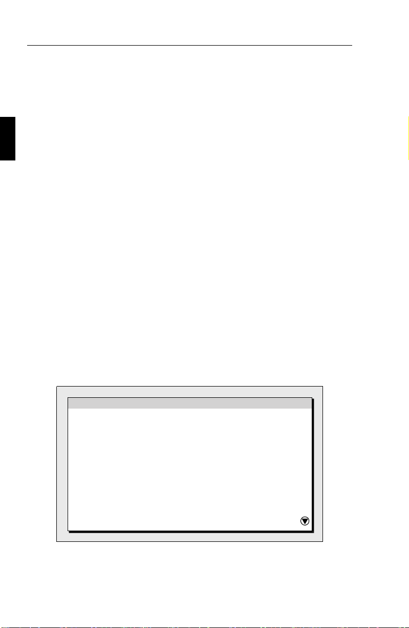
OSM (On-Screen Manager) Controls
The OSM (On-Screen Manager) controls simplify the MultiSync’s
Advanced Digital Control System. The control system is easily
accessed. Just touch the PROCEED button on the front of the monitor,
which gives you access to the Position, Image Adjust and Contrast
controls, the ColorControl System and many others. Use the front
controls for navigation.
ON SCREEN MANAGER
Position
Image Adjust
Contrast
AccuColor
OSM Location
OSM Turn Off Time
OSM Lock Out
Page 10

Introduction to the NEC MultiSync LCD200 E- 5
Through the OSM control’s enhanced ColorControl System, you can
better match your image color to a variety of standards such as:
– Your personal preference (depending upon the application
used).
– A color standard such as Pantone or Trumatch.
– Another monitor.
– Your printer or Service Bureau output.
Additional OSM controls are available such as OSM Location, OSM
Turn Off Time, OSM Lock Out, Display Mode, Language Select and
Factory Preset.
Page 11
E - 6 Contents of Package
Contents of Package
Included with your MultiSync LCD200 monitor are the following items:
– NEC MultiSync LCD200 (Model LA-122lJMW) true color
monitor.
– AC power cable.
– Video signal cable (15 pin mini D-sub male to 15 pin mini
D-sub male).
– User’s manual.
Remember to save the original box and packing materials to transport or
ship this monitor.
Page 12

Recommended Use E - 7
Recommended Use
For optimum performance, please note the following when setting up
and using the MultiSync LCD
• The optimum monitor position is facing away from direct
sunlight.
• Allow adequate ventilation around the monitor so that heat
can properly dissipate.
• Do not place any heavy objects on the power cord. Damage
to the cord may cause shock or fire.
• Use the monitor in a clean and dry area.
• Handle with care when transporting. Save packaging for
transporting.
• When operating the MultiSync LCD200 with its AC125-
240V worldwide power supply, use a power supply cord
that matches the power supply voltage of the AC power
outlet being used. The power supply cord you use shall be
employed one of the type H05VV-F with the earth pin,
which must have been approved by and comply with the
safety standards of your country.
200 color monitor:
• The power cable connector is the primary means of detaching
the system from the power supply. The monitor should be installed close to a power outlet which is easily accessible.
• Clean the LCD monitor surface with a lint-free, non-abrasive
cloth. Avoid using any cleaning solution, glass cleaner or tissue paper.
• For optimum performance, allow 20 minutes for warm-up.
• Avoid displaying fixed patterns on the monitor for extremely
long periods of the time to avoid after-image effects.
• Avoid applying pressure to the LCD monitor surface.
Page 13

E - 8 Installation
Installation
Connection to your Personal Computer
(NEC and PC Compatibles)
The MultiSync LCD200 true color monitor complements NEC and PC
compatible computers. Your system has one of two configurations:
– the video controller is built into the computer.
– the video controller is in the form of a display card (sometimes
referred to as graphics card, video adapter or graphics board).
Both configurations have a video connector (or a CRT PORT on laptop
computers). If you are not sure which connector is the video connector,
refer to your computer or display card manual.
To attach the monitor to your system, follow these instructions:
1. Turn off the power to the monitor and computer.
2. If necessary, install the display card. For more information
about installing your card, refer to the display card manual.
3. Connect the MultiSync LCD
display card’s connector.
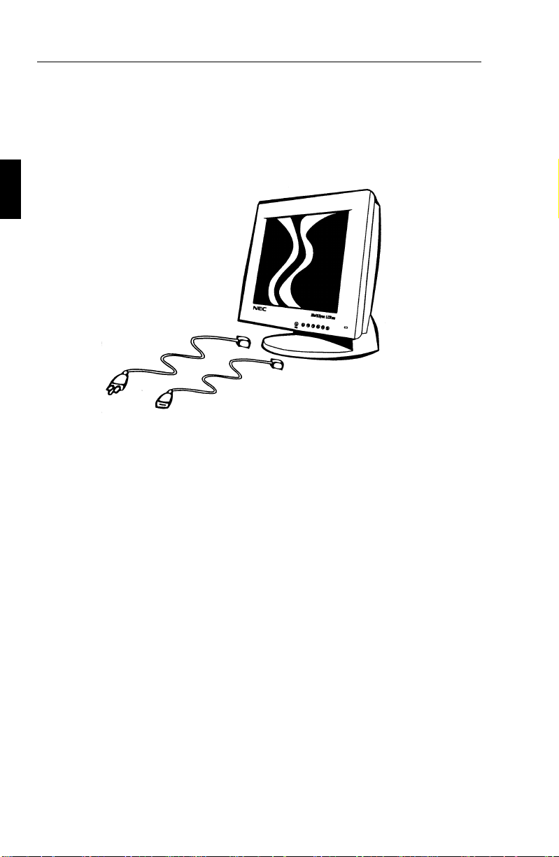
4. Connect one end of the power cable to the MultiSync monitor
and the other end to the power outlet.
5. Turn on the monitor and the computer.
6. This completes the installation.
If you have any problems, please refer to the Troubleshooting section of
this manual.
200 monitor’s video cable to the
Page 14

Installation E - 9
Connection to your Personal Computer (Macintosh)
With the Macintosh cable adapter, the MultiSync LCD200 color monitor
is compatible with the Macintosh family of computers, Power
Macintosh, Mac Quadra Series, Mac Centris Series, Mac LC series,
Mac Performa series, PowerBooks and other NuBus/PCI display cards
@ 640x480, 800x600, and 1024x768 resolutions.
You will connect your MultiSync color monitor one of two ways to
your Macintosh computer:
– On-board video port
– NuBus/PCI/PDS display card
Both configurations should have the same style video connector. If you
are not sure which port is the monitor connector, please reference your
computer or display card manual.
To attach the monitor to your system, follow these instructions:
1. Turn off the power to your MultiSync monitor and Macintosh.
2. If necessary, install the display card. For more information on
this installation, reference the display card manual.
3. If necessary, install the 15-pin to 15-pin MultiSync LCD
Macintosh cable adapter to the monitor connector. Tighten the
screws.
4. Connect the MultiSync monitor’s signal cable to the other end
of the cable adapter. Tighten the screws between the signal
cable and cable adapter to ensure proper connection.
5. Connect one end of the power cable to the MultiSync monitor
and the other end to the power outlet.
6. If you have a Powerbook, Mac LC, Mac AV, Power Mac or
Quadra 605 or 630 or are running system 7.5, please make sure
the SYNC switch is in the ON position. (The SYNC switch is
located on the back of the monitor). All other Mac systems
require the SYNC switch to be in the OFF position.
7. Turn on the monitor and the computer.
200
Page 15

E - 10 Installation
8. This completes the installation.
Power Macintosh 6100/60 and 66 users need to use the Apple HDI-45
cable adapter and Powerbook users need to use the Apple VID-14 cable
adapter in conjunction with the appropriate MultiSync Macintosh cable
adapter when connecting a MultiSync monitor.
Connection to Other Computers or Display Cards
If your computer or display card is not compatible with the MultiSync
LCD
200 color monitor’s PRESET signals or has a different pin
assignment, refer to the steps below to determine if your system is
compatible with the MultiSync LCD
1. Determine the video connector’s pin assignments of your
display card.
2. Determine the output signal timing and level of your display card.
3. Check the pin assignment and signal timing charts of the display
card and make sure the monitor accepts these pin assignments
and signal timings.
200 color monitor.
4. Select the appropriate SYNC switch setting on the rear of the
monitor according to your computer or display card output.
SYNC switch should be set in the ON position for standard
separate or composite Sync mode and in the OFF position for
Sync on Green priority mode.
5. Connect the signal cable supplied with your display card to the
monitor.
6. Connect one end of the power cable to the MultiSync LCD
200
monitor and the other end to the power outlet.
7. Turn on the monitor and the computer.
8. Adjust the position of the image to your preference.
9. This completes the installation.
If you have any problems, please refer to the Troubleshooting section of
this manual.
Page 16
Controls E - 11
Controls
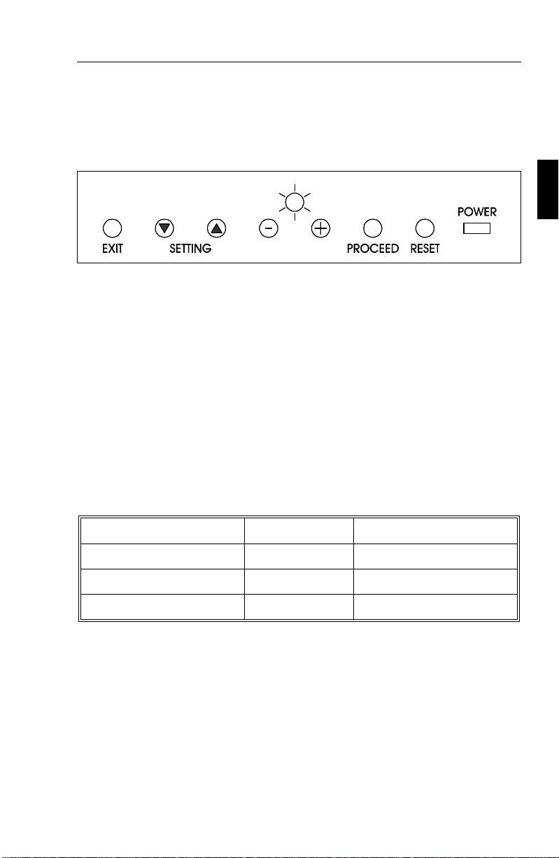
Direct Controls
EXIT: Has no function
SETTING ▼/▲: Selects between two sets of parameters for each
resolution. Each selection can be preset by adjusting the OSM controls
to your preference. Changes are saved automatically.
LCD Brightness -/+: Adjusts the overall image and background screen
brightness.
PROCEED: Accesses OSM controls menu
RESET: Has no function
LED Power Indicator Light: Located on the lower right and indicates
the monitor’s power mode. Each mode reduces the amount of power
used by the monitor.
Mode LED Indicator Power Consumption
ON Green Typical: 33 watts
Standby & Suspend Amber Typical: About 6 watts
Power Switch OFF No Light No Power Used
Power Switch: Located on the right side of the monitor’s base which
turns the monitor power on or off. When the power is on, the LED is lit.
SYNC Switch: Located on the rear of the monitor, which allows
selection between standard separate and composite Sync modes (ON)
and Sync on Green priority mode (OFF).
Page 17
E - 12 Controls
OSM Controls
The OSM controls on the front of the monitor provide the following
functions:
Control In the Main Menu In the Sub Menu
EXIT ▼/▲ Exits the OSM controls. Exits to the OSM
controls menu.
SETTING Moves the highlighted
area up/down to select
one of the controls.
SETTING -/+ Has no function. Moves the bar in the +
PROCEED Proceeds to selected
menu choice (indicated
by the highlighted area).
RESET: The currently
highlighted control to
the factory setting.
Resets all the controls
within the highlighted
menu.
Moves the highlighted
area up/down to select
one of the controls
or - direction to increase
or decrease the
adjustment.
Proceeds to the control
in that sub menu.
Resets the highlighted
control.
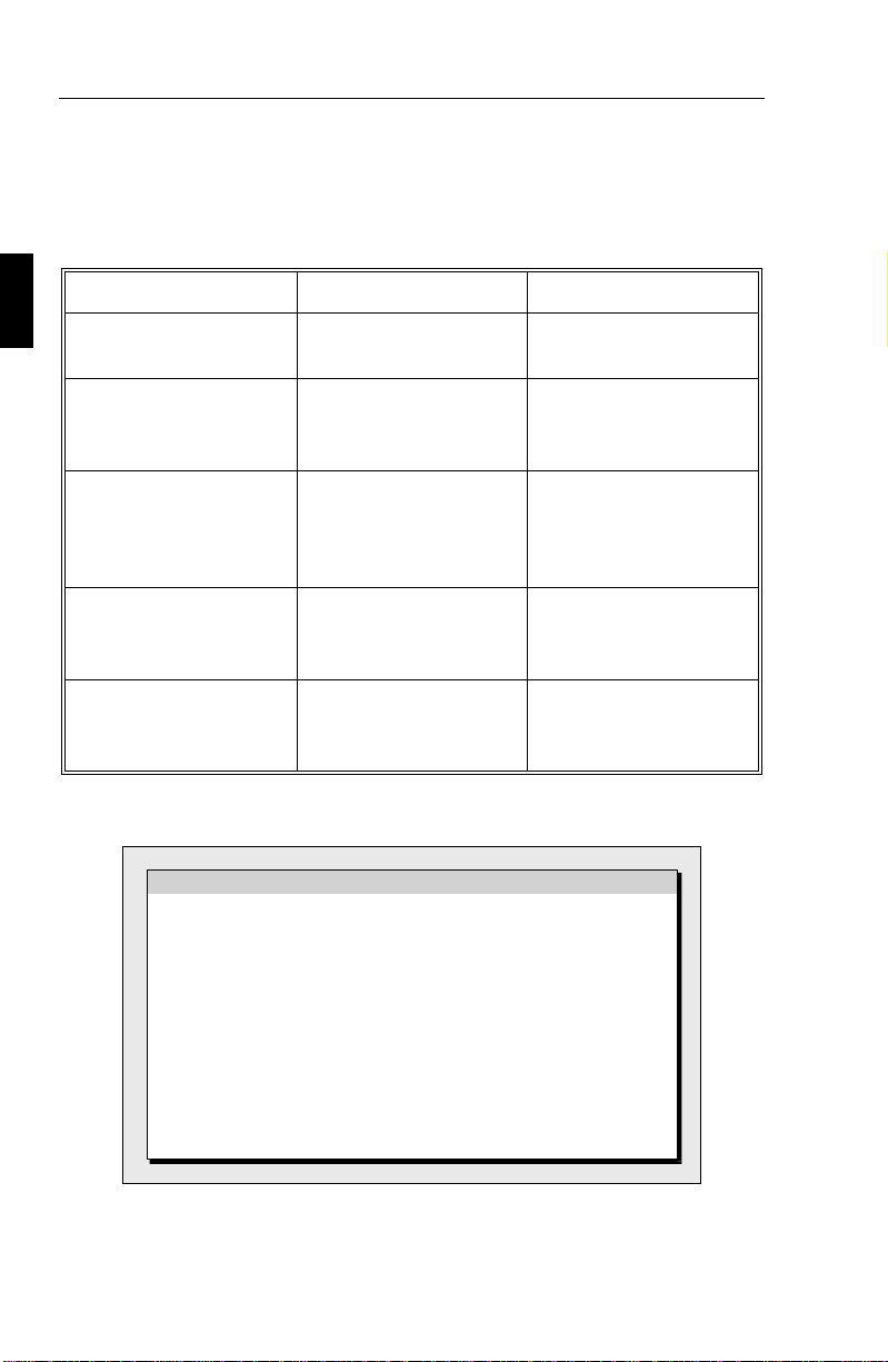
NOTE: When RESET is pressed, a warning window will appear
allowing you to cancel the reset function.
WARNING
ABOUT TO RESET
POSITION
Press:
PROCEED-Reset
EXIT-Cancel
Page 18

OSM Control Menus E - 13
OSM Control Elements
Typical On Screen Manager windows have the following elements:
Control Function
Highlight Indicates the selected menu or Control
Scroll Bar Indicates direction of adjustment
Numeric Reading Provides a number to remember, record or compare a
specific setting.
OSM Control Menus
Main Menu
ON SCREEN MANAGER
Position
Image Adjust
Contrast
AccuColor
OSM Location
OSM Turn Off Time
OSM Lock Out
The arrow in the bottom or upper right corner indicates that further
choices are available. Use the ▼/▲ control buttons to scroll through all
of the options.
Page 19

E - 14 OSM Control Menus
Position Menu
Up/Down: Moves the image vertically up or down.
Left/Right: Moves the image horizontally left or right.
Position
Up
Left
Down
Right
Image Adjust
Adjust the horizontal size of the image by increasing or decreasing the
coarse total. Focus, clarity and image stability can be improved by
increasing or decreasing the Fine total.
Image Adjust
Coarse
Fine
1280
31
Page 20

OSM Control Menus E - 15
Contrast
The contrast level of the monitor’s display can be adjusted by increasing
or decreasing the total.
Contrast
Contrast
100
AccuColor Control System Menu
Preset(Setting): Selects the desired color setting. The bar is replaced by
the color setting choice (from 1 to 3). Each color setting is adjusted at
the factory to the stated degree Kelvin. If a setting is adjusted, the name
of the setting will change from degree Kelvin to Custom.
AccuColor
Preset: 6600 Kelvin
123
Color Gain:
Red
Green
Blue
100
100
100
Color Gain: Increases or decreases red, green or blue depending upon
which is selected. The change in color will appear on screen and the
direction (increase or decrease) will be shown by the color bars. One
Page 21

E - 16 OSM Control Menus
color is always used as the reference color, and therefore, will not
change when adjusted.
Note on Controls in AccuColor Control System Menu:
Exit: Exits to the main menu.
Cursor up/down: Moves the highlighted area up/down to select one of
the choices.
Cursor +/-: Moves the bar in the + or – direction to increase or
decrease the adjustment or selects the color setting (l through 3).
Proceed: Proceeds to the next control in the sub-menu.
Reset: Resets the current highlighted color setting to the factory setting.
The current color settings on your monitor were determined by focus
groups and end users’ panels to be the most popular settings for the
majority of applications.
Your adjustments are automatically saved instantly.
OSM Location
You can choose where you would like the OSM control image to appear
on your screen. Selecting OSM Location allows you to manually adjust
the OSM control menu left, right, up or down.
OSM Location
Left
Up
Right
Down
Page 22

OSM Control Menus E - 17
OSM Turn Off Time
The OSM control menu will stay on as long as it is in use. In the OSM
Turn Off Time submenu, you can select how long the monitor waits
after the last touch of a button to shut off the OSM control menu. The
preset choices are 10, 20, 30, 60 and 120 seconds.
OSM Turn Off Time
Seconds:
10 20 30 60 120
OSM Lock Out: This control completely locks out access to all OSM
control functions. When attempting to activate OSM controls while in
the lock out mode, a screen will appear indicating that OSM controls are
locked out. To activate the OSM Lock Out function, press PROCEED,
then ▲ and hold down simultaneously. To de-activate the OSM Lock
Out, press PROCEED, then ▲ and hold down simultaneously.
OSM Lock Out
See User’s Manual
for More Information
Page 23

E - 18 OSM Control Menus
Display Mode
Display Mode provides you with information about the current
resolution display and technical data including the preset timing being
used and the horizontal and vertical frequencies.
NOTE: Mode Change should only be used if a resolution is not
recognized correctly by the monitor. The user can change to the
appropriate resolution by entering the Mode Change sub-menu and
selecting the corresponding option.
Display Mode
Preset 14
Mode: 1024 x 768
H Freq: 48.2 kHz
V Freq: 60.1 Hz
H/V Pol: Neg/Neg
Press:
PROCEED-Mode Change
Language Select
OSM control menus are available in six languages.
Language Select
English
Deutsch
Françals
Español
Italiano
Svenska
Page 24

OSM Control Menus E - 19
Factory Preset
Selecting Factory Preset allows you to reset all OSM control settings
back to the factory settings. The following warning statement will
appear to confirm that you do want to reset ALL settings. The RESET
button will need to be held down for several seconds to take effect.
Individual settings can be reset by highlighting the control to be reset
and pressing the RESET button.
WARNING
ABOUT TO RESET
ALL SETTINGS
Press:
RESET-Reset
EXIT-Cancel
Page 25

E - 20 Specifications
Specifications
Display: 12.1-inch (30.7 cm viewable image size); active
matrix; thin film transistor (TFT); liquid crystal
display (LCD); 0.24 mm dot pitch; RGB vertical stripe
color filter arrangement; 200 cd/m² white luminance,
typical; 150:1 contrast ratio, typical
Compatibility: 720 x 400: VGA text
640 x 480: VGA, 60 Hz to 85 Hz vertical refresh
800 x 600: 56 Hz to 85 Hz vertical refresh
1024 x 768 non-interlaced: 60 Hz to 75 Hz vertical
refresh
Synchronization
Frequencies:
Resolution: Horizontal: 1024 dots
Active Display Area: Horizontal: 245.8 mm
Viewing Angles: Up 20°
Horizontal: 24.8 kHz to 62.0 kHz
Vertical: 53.7 Hz to 85 Hz (up to 75 Hz
for l 024 x 768)
Pixel Frequency: 21.1 MHz to 78.8 MHz
H Sync Jitter: Less than 10% of pixel
frequency (recommended)
Vertical: 768 lines
Vertical: 184.3 mm
Down 20°
Right 30°
Left 30°
Page 26

Specifications E - 21
Input Signal: Video: Analog Red, Green, Blue
(Video 0.7 Vp-p)
Input Impedance:75 ohms
Sync: Separate Sync: TTL level
Horizontal Sync: positive/negative
Vertical Sync: positive/negative
Composite Sync: TTL level, positive/negative
Sync on Green
video:
Display Colors: Unlimited colors (depends on graphics interface and/or
application)
Signal Cable: 15-pin mini D-sub male to 15-pin mini D-sub male
Power Supply: AC 100 to 240 V worldwide input, 50/60 Hz
Power Consumption: Typical: 33 watts in ON mode, under 6 watts in power
saving mode.
Dimensions (W,H, D) 344 x 340 x 171 mm
Weight: Net: 4.0 kg
Gross: 6.0 kg
Tilt Rotation: Up: 25 degrees
Down: 5 degrees
Environmental: Operating
temperature:
Storage temperature: -10°C to 60°C, 14°F to 140°F,
0.3 Vp-p negative
5°C to 35°C, 4l°F to 95°F;
humidity 80% maximum
humidity 85% maximum
Note: All technical specifications are subject to change without notice.
Page 27

E - 22 Troubleshooting/Support
Troubleshooting/Support
Problem Check These Items
No pictures - The signal cable should be completely connected to
the display card/computer.
- The display card should be completely seated in its
slot.
- Power Switch and computer power switch should be
in the ON position.
- Check to make sure that a supported mode has been
selected on the display card or system being used.
(Please consult display card or system manual to
change graphics mode.)
- Check the monitor and your display card with
respect to compatibility and recommended settings.
- Check the signal cable connector for bent or
pushed-in pins.
- Check to see that SYNC switch setting on the rear of
the monitor corresponds with the computer or display
card output (please see Controls section of manual for
a description of SYNC switch settings).
Image is unstable,
unfocused or
swimming is
apparent
LED on the monitor
is not lit (no green
or amber color can
be seen)
Display image is not
centered
- Signal cable should be completely attached to the
computer.
- Use the OSM Image Adjust controls to focus and
adjust display by increasing or decreasing the fine
total. When the display mode will be changed, the
OSM Image Adjust settings may need to be
re-adjusted.
- Check the monitor and your display card with
respect to compatibility and recommended signal
timings.
- Power Switch should be in the ON position and the
power cord should be connected.
- Make certain the computer is not in a power-saving
mode (touch the keyboard or mouse).
Use OSM Position adjustment controls to adjust
centering.
Page 28

Troubleshooting/Support E - 23
Display image is not
sized properly
Selected resolution
is not displayed
properly
- Use the OSM Image Adjust controls to increase or
decrease the Coarse total.
- Check to make sure that a supported mode has been
selected on the display card or system being used.
(Please consult display card or system manual to
change graphics mode.)
Use OSM Display Mode to enter Mode Change sub
menu and confirm that the appropriate resolution has
been selected. If not, select corresponding option.
Page 29

Deutsch
Page 30

Vorstellung des NEC MultiSync LCD200 D - 1
Vorstellung des NEC MultiSync LCD200
Herzlichen Glückwunsch zum Kauf Ihres NEC MultiSync LCD
200
Farbmonitors.
Der NEC LCD
200 Farbmonitor ist mit einer von NEC entwickelten
vollfarbfähigen LCD-Anzeige von 30,7 cm Diagonale ausgestattet.
Diese LCD-Anzeige ist in Aktiv Matrix Dünnfilmtechnologie (TFT)
gefertigt. So verfügt der LCD-Monitor über eine exzellente Bildqualität
bei einer Gerätetiefe von weniger als 18 cm. Er eignet sich ideal für alle
Anwendungsbereiche in denen Einsparungen an den Abmessungen und
am Gewicht eines Monitors gefordert werden, jedoch auf eine
exzellente Bildqualität mit Auflösungen bis zu 1024 x 768 Bildpunkten
und einer Pixelgröße von 0,24 mm nicht verzichtet werden kann.
Wie es sich für ein Gerät mit dem Namen MultiSync gehört, kann der
Monitor auch Auflösungen von 800 x 600 Bildpunkten und alle VGA
Grafik- und Textmodi darstellen.
Der LCD
200 Farbmonitor ist Microsoft Plug and Play kompatibel undnach
den NEC ErgoDesign Richtlinien entwickelt. Alle Einstellungen am Gerät
werden über den interaktiven On Screen Manager vorgenommen.
Analog ist besser
Durch die Nutzung von NEC eigenen Patenten in der Fertigung der
vollanalogen LCD-Anzeige ist es möglich, jeden Bildpunkt mit über
16,7 Millionen unterschiedlichen Farbnuancen darzustellen. Ähnlich
einem analogen Monitor mit Bildröhre können so auch kontinuierliche
Grautöne und Verläufe ohne störende Rasterungen dargestellt werden.
Die digitalen LCD’s können durch ihre limitierte Anzahl von
darstellbaren Farben eine Reihe von Farben nur gerastert anzeigen.
Zusätzlich bieten die von NEC gefertigten LCD-Anzeigen einen sehr
hohen Kontrast, gute Farbbalance und ausgezeichnete Bildschärfe ohne
Störungen der Bildgeometrie.
Page 31

D - 2 Vorstellung des NEC MultiSync LCD200
Anschlußvielfalt
Im LCD200 MultiSync Monitor werden nach dem neuesten Stand der
Satellitentechnik gefertigte, hochmoderne Schaltkreise eingesetzt. So
gewährleistet NEC eine weitgehende Kompatibilität zu den aktuellen
Grafikkarten und Grafikkomponenten der Computeranbieter. Der LCD
200
Monitor ist durch und durch analog konzipiert, so daß keine komplizierten
analog/digital Wandlungen zu Anschlußproblemen führen. Als Umkehrschluß können in allen Einsatzgebieten des LCD
200 Monitors ohne
Probleme alternativ Röhrenmonitore zum Einsatz kommen. Der NEC
MultiSync LCD
200 kann mit einem breiten Spektrum von Systemen
benutzt werden, z. B. Computer nach dem Industriestandard, Apple
Macintosh und Power Macintosh.
FullScan
FullScan ist die von NEC entwickelte Eigenschaft eines Monitors, bei allen
Bildschirmauflösungen immer die maximale Bildschirmfläche zu nutzen. So
wird z.B. bei einer VGA Auflösung von 640 x 480 Bildpunkten nicht nur der
mittlere Bereich der LCD-Anzeige genutzt, sondern der gesamte sichtbare
Bereich der Anzeige. Durch diese Funktion können die Bildinhalte bei
geringeren Bildauflösungen optimalvermitteltwerden.
Minimierte Stellfläche
Der LCD200 Monitor hat beinahe die gleiche sichtbare Anzeigefläche
wie ein 14" oder 15" Monitor; jedoch im Vergleich eine um 60%
verringerte Stellfläche und ein um 70% verringertes Gewicht. Rund
17 cm Gehäusetiefe und ca. 4 kg Gewicht erlauben den Einsatz in allen
Bereichen; speziell dann, wenn eine hohe Bildschirmauflösung bei
geringem verfügbaren Platz gefordert wird. Als kleines, leichtes
Arbeitsgerät kann der LCD
200 ohne Probleme von einer Einsatzstelle
zur nächsten transportiert werden.
Power Manager
Der Intelligent Power Manager (Intelligenter Energiesparer), abgekürzt
IPM, ist eine fortschrittliche Einrichtung zum Energiesparen. Nach den
Richtlinien des Energy Star der amerikanischen Umweltbehörde und der
europäischen NUTEK konzipiert, spart der LCD
200 Monitor Energie und
Page 32

Vorstellung des NEC MultiSync LCD200 D - 3
Kosten, indem er bei Arbeitspausen teilweise abgeschaltet wird.
Verantwortlich für das stufenweise Abschalten des Monitors ist die
Grafikkarte des Computers, die nach einem durch die VESA (Video
Electronics Standard Association) spezifizierten Verfahren (DPMS) die
horizontalen und vertikalen SYNC-Signale abschaltet und so dem
Monitor signalisiert, wie er sich zu verhalten hat.
Der maximale Energieverbrauch des LCD200 liegt bei 33 Watt und
somit bei etwa der Hälfte des Verbrauchs eines konventionellen
Monitors mit Bildröhre. In den Stromsparmodi werden lediglich 6 Watt
verbraucht, was nicht nur den Energieverbrauch reduziert, sondern
gleichzeitig die Wärmeabgabe deutlich vermindert.
Hinweis: Die Energiespareinrichtung kann nur von einer Grafikkarte
aktiviert werden, die diese Funktion gemäß DPMS von VESA unterstützt.
Dem Anwender signalisiert der Monitor seinen aktuellen Status durch
die Netz LED nach folgender Tabelle:
Modus LED Energieaufnahme
ON grün ca. 33 Watt
Stand by (Bereitschaft) und
Suspend
Ausgeschaltet aus (dunkel) Kein Stromverbrauch
orange ca. 6 Watt
(ausgeschaltet)
Plug and Play
Plug and Play ist die in Windows 95 integrierte Antwort von Microsoft
auf Probleme bei der Installation von EDV- und Peripheriegeräten. Der
LCD
200 Monitor teilt seinen Typ und seine Leistungsmerkmale
normgerecht dem System mit, so daß von diesem automatisch die
bestmögliche Auflösung und Bildwiederholrate eingestellt wird, wenn
es sich dabei um ein Plug and Play kompatibles System und Grafikkarte
handelt. Dies ermöglicht Ihnen einfachste Installation, Konfiguration
und Einstellung Ihres NEC Monitors.
Page 33

D - 4 Vorstellung des NEC MultiSync LCD200
Ergo Design
Der LCD200 Monitor ist strikt nach den Richtlinien des ErgoDesigns
entwickelt worden. ErgoDesign beschreibt eine Philosophie mit dem
Ziel, dem Benutzer von NEC MultiSync Monitoren ein Maximum an
Komfort und Produktivität zu bieten. Hierzu gehört neben der
ergonomischen Anordnung der Bedienelemente und den
Einstellmöglichkeiten des Betrachtungswinkels auch der Schutz der
Gesundheit des Benutzers, finanzielle Einsparungen durch normierte
Stromsparfunktionen sowie Recycling.
Emissionstest
ErgoDesign steht neben einem gefälligen Gehäuse auch für reduzierte
elektrische und magnetische Feldstärke. Die NEC MultiSync Monitore
sind so entwickelt worden, daß von elektrischen und magnetischen
Feldern ausgehende potentielle Gefahren einer andauernden
Bildschirmarbeit weitgehend vermieden werden.
OSM-Menü
Das OSM-Menü (On Screen Manager) von NEC zeigt die derzeit
komfortabelste Art der Monitoreinstellung. Tasten an der Vorderseite
des Monitors helfen Ihnen bei der Navigation durch ein grafisches
Menüsystem.
ON SCREEN MANAGER
Bildlage
Bildeinstellung
Kontrast
ColorControl
OSM Position
OSM Anzeigedauer
OSM Abschaltung
Page 34

Lieferumfang D - 5
Mit dem OSM-Menü können die Parameter Bildgröße, Bildlage,
Bildgeometrie und Farbanpassung des Digital Control-Systems
gesteuert werden. Alle Einstellungen werden nach ca. 5 Sekunden
dauerhaft gespeichert. Die Einstellungen des jeweils aktiven
Menüpunktes können jederzeit durch Drücken des Reset-Knopfes auf
die Werkeinstellungen zurückgesetzt werden.
Lieferumfang
Die folgende Übersicht zeigt den Lieferumfang Gerätes. Öffnen Sie
vorsichtig die Verpackung Ihres Monitors und entnehmen Sie alle zum
Monitor gehörenden Teile. Sollten Teile fehlen oder beschädigt sein, so
wenden Sie sich bitte umgehend an Ihren NEC-Fachhändler. Karton
und Verpackungsmaterial sollten Sie für einen späteren Transport Ihres
Monitors aufbewahren.
– NEC MultiSync LCD200 (LA-1221JMW) Farbmonitor
– Netzkabel
– Videosignalkabel (15 pin mini D-sub auf 15 pin mini D-Sub)
– Bedienerhandbuch
Page 35

D - 6 Aufstellen
Aufstellen
Um eine optimale Abbildungsqualität Ihres Monitors zu gewährleisten,
sollten Sie folgende Punkte bei der Aufstellung des Monitors beachten:
• Plazieren Sie den Monitor nicht in direktem Sonnenlicht.
• Achten Sie darauf, daß die Lüftungsschlitze des Monitors nicht
verdeckt sind, um eine optimale Wärmeabfuhr zu gewährleisten.
• Stellen Sie keine schweren Gegenstände auf das Netzkabel
des Monitors. Beschädigte Netzkabel können zu Brand oder
Stromschlag führen.
• Benutzen Sie den Monitor nur in trockener, sauberer Umgebung.
• Transportieren Sie den Monitor mit der nötigen Vorsicht.
• Der MultiSync LCD200 hat ein Universal-Netzteil und
kann mit Netzspannungen von 125 V bis 240 V betrieben
werden. Gundsätzlich sollten Sie zum Anschluß das mitgelieferte Netzkabel benutzen. Falls der Stecker dieses
Netzkabels nicht für Ihre Steckdose geeignet ist, benutzen
Sie bitte ein passendes Netzkabel des Types H05VV-F mit
Schutzkontakt, das in Ihrem Land entsprechend den Sicherheits-Standards zugelassen ist.
• Zur vollständigen Trennung vom Stromnetz ist der Netz-
bzw. Gerätestecker zu ziehen.
• Schließen Sie den Monitor an eine Steckdose an, die sich
leicht zugänglich, in der Nähe des Gerätes befinden muß.
• Zur Reinigung der Display-Oberfläche benutzen Sie am be-
sten ein weiches Tuch. Benutzen Sie keine Reinigungsflüssigkeit oder Papiertücher.
• Um seine optimale Abbildungsleistung zu erreichen, benötigt
der Monitor ca. 20 Minuten Zeit zur Aufwärmung.
Page 36

Installation D - 7
• Vermeiden Sie die Darstellung sich nicht verändernder Ab-
bildungsmuster über einen extrem langen Zeitraum, um Beeinträchtigungen der Displayqualität zu verhindern.
• Vermeiden Sie Druckeinwirkungen auf die LCD-Oberfläche.
Installation
Anschluß an NEC-, IBM- und kompatible PC’s
Der LCD200 MultiSync Farbmonitor ist geeignet für den Einsatz an
NEC PC’s oder nach dem Industriestandard kompatible Computern. Ihr
System sollte entweder einen eingebauten Grafikadapter oder eine
installierte Grafikkarte besitzen. Beide Varianten haben eine
Videoausgangsbuchse zum Anschluß eines Monitors. Sollten Sie nicht
sicher sein, an welche Buchse der Monitor anzuschließen ist, so lesen
Sie dies im Benutzerhandbuch der Grafikkarte oder des Computers
nach. Im Zweifelsfall fragen Sie Ihren NEC-Fachhändler.
Beim Anschluß eines Monitors an Ihren Computer sind folgende Punkte
zu beachten:
1. Schalten Sie die Stromversorgung von Computer und Monitor
aus.
2. Falls notwendig, installieren Sie eine Grafikkarte nach den
Anweisungen im Benutzerhandbuch der Grafikkarte.
3. Schließen Sie das Signalkabel am Signaleingang des LCD
Monitors und an der entsprechende Videobuchse Ihres
Computers an.
4. Verbinden Sie das mitgelieferte Netzkabel auf einer Seite mit
dem Monitor und auf der anderen Seite mit einer geerdeten
Wandsteckdose in der Nähe des Monitors.
5. Schalten Sie Monitor und Computer ein.
6. Hiermit ist der Anschluß des Monitors abgeschlossen.
Sollten sich hierbei Probleme ergeben, so lesen Sie bitte den Abschnitt
„Hilfe bei Problemen”.
Page 37

D - 8 Installation
Anschluß an Macintosh Computer
Der LCD200 Farbmonitor ist geeignet für den Anschluß an Computer der
Macintosh Familie, Power Macintosh, Mac Quadra Serie, Mac Centris Serie,
PowerBook Computern und anderen NuBus oder PCI Grafikkarten der
AppleWeltmitGrafikauflösungenvon640x480,800x600und1024x768
Bildpunkten. Hierzu wird ein gesondert erhältlicher Macintosh Adapter
benötigt, den Sie bei Ihrem NEC-Fachhändler erwerben können. Ihr System
sollte entweder einen integrierten Grafikadapter oder eine in einem NuBus,
PCI oder PDS-Steckplatz eingebaute Grafikkarte besitzen. Alle Varianten
haben eine Videoausgangsbuchse zum Anschlußeines Monitors.
Benutzer eines Power Macintosh 6100/60 oder 66 benötigen zum
Anschluß des Monitors das mit dem Computer gelieferte Kabel HDI-45
und PowerBook Benutzer benötigen das Kabel VID-14 zusätzlich zum
optional erhältlichen Macintosh Adapter.
Verfahren Sie wie folgt, um Ihren Monitor an einen Macintosh
Computer anzuschließen:
1. Schalten Sie die Stromversorgung von Computer und Monitor aus.
2. Falls notwendig, installieren Sie eine Grafikkarte nach den
Anweisungen im Benutzerhandbuch der Grafikkarte.
3. Schließen Sie den optional erhältlichen MacintoshAdapterstecker am Videoausgang des Computers an und sichern
Sie die Verbindung durch Festziehen der Schrauben.
4. Verbinden Sie das Signalkabel mit dem Signaleingang des Monitors und mit dem am Computer befestigten Macintosh-Adapter.
5. Verbinden Sie das mitgelieferte Netzkabel auf einer Seite mit
dem Monitor und auf der anderen Seite mit einer geerdeten
Wandsteckdose in der Nähe des Monitors.
6. Sind Sie Besitzer eines Powerbook, MacLC, Mac AV, Power
Mac oder Mac Quadra 605 oder 630, so stellen Sie sicher, daß
sich der SYNC-Schalter an der Geräterückseite in Position ON
befindet. Bei allen anderen Computern aus dem Hause Apple
muß sich der SYNC-Schalter in Stellung OFF befinden.
7. Schalten Sie Monitor und Computer ein.
Page 38

Installation D - 9
Anschluß an andere Computersysteme
Möchten Sie Ihren LCD200 Farbmonitor an ein Computersystem oder
an eine Grafikkarte anschließen, die nicht mit dem im Anhang
(Appendix) beschriebenen PRESET-Signal kompatibel sind, oder deren
Anschlußbelegung von der im Anhang beschriebenen abweicht, so
verfahren Sie wie folgt:
1. Schalten Sie Monitor und Computer aus.
2. Überprüfen Sie die Anschlußbelegung der Ausgangsbuchse
Ihres Computersystems oder Ihrer Grafikkarte.
3. Überprüfen Sie Signalverhalten und Amplitude Ihrer
Grafikkarte und stellen Sie sicher, daß Anschlußbelegung und
Signalverhalten mit denen des LCD
sind.
4. Stellen Sie den SYNC-Schalter an der Geräterückseite in
Position ON für Computer die Composite oder Separate Sync
Signale zur Verfügung stellen und in Position OFF wenn der
Computer Sync on Green liefert.
200 Monitors kompatibel
5. Verbinden Sie das Signalkabel mit dem Signaleingang des
Monitors und mit dem Videoausgang des Computers.
6. Verbinden Sie das mitgelieferte Netzkabel auf einer Seite mit
dem Monitor und auf der anderen Seite mit einer geerdeten
Wandsteckdose in der Nähe des Monitors.
7. Schalten Sie Monitor und Computer ein.
8. Justieren Sie Größe und Lage der Abbildung nach Ihren
Anforderungen.
9. Dies beendet die Installation.
Sind Sie nicht sicher, ob Ihr LCD
200 Farbmonitor für den gewünschten
Einsatzzweck geeignet ist, so fragen Sie Ihren autorisierten
NEC-Fachhändler.
Page 39

D - 10 Bedienelemente
Bedienelemente
Die folgende Abbildung zeigt die Lage der Tasten zur Bedienung des
LCD
200 Farbmonitors.
Die Bedienelemente des LCD
Funktionen innerhalb und außerhalb des OSM Menüs.
200 Monitors haben unterschiedliche
Funktionen außerhalb des OSM Menüs (direkte Funktion)
Die Taste EXIT hat keine direkte Funktion.
Die Setting-Tasten ▼ und ▲ wählen zwischen zwei Parametergruppen.
Jede Einstellung kann im OSM Menü mit Vorgaben belegt werden. Alle
Änderungen werden automatisch gespeichert.
Der Helligkeitsregler + und - regelt die gesamte Helligkeit der
Abbildung.
Mit der Taste PROCEED wird das OSM Menü aufgerufen.
Die Taste RESET hat keine direkte Funktion.
Die Netz-LED zeigt den Betriebszustand des Monitors an. Hierbei kann
die LED unterschiedliche Farben annehmen. Die Bedeutung der
einzelnen Farben kann der folgenden Tabelle entnommen werden.
Page 40

Bedienelemente D - 11
Modus LED Energieaufnahme
ON grün ca. 33 Watt
Stand by (Bereitschaft) und
Suspend
Ausgeschaltet aus (dunkel) Kein Stromverbrauch
orange ca. 6 Watt
(ausgeschaltet)
Mit dem Netzschalter an der rechten Seite wird der Monitor ein- und
ausgeschaltet.
Der an der Geräterückseite angeordnete SYNC Schalter erlaubt eine
Anpassung des Monitors an die vom Computer bereitgestellten SYNC
Signale (Position OFF für SYNC on green, Position ON für Composite
oder Separate SYNC Signale).
Funktionen innerhalb des OSM Menüs.
Mit der Taste EXIT wird der aktuelle Menüpunkt, im Hauptmenü das
OSM-Menü verlassen.
Die SETTING-Tasten ▼ und ▲ steuern den hervorgehobenen Bereich
nach oben oder unten um einen Menüpunkt auszuwählen.
Der Helligkeitsregler + und - hat im Hauptmenü keine Funktion, im
Untermenü werden damit die ausgewählten Einstellungen erhöht oder
erniedrigt.
Die Taste PROCEED dient der Auswahl eines markierten
Menüpunktes. Im Hauptmenü wird so in einen Untermenüpunkt
verzweigt, im Untermenü eine Auswahl bestätigt.
RESET setzt die Einstellungen des aktiven Menüpunktes auf die
Werkeinstellungen zurück. Wird diese Taste im Hauptmenü gedrückt, so
werden alle Parameter des markierten Untermenüs, in einem Untermenü
nur der aktuelle Parameter auf die Werkeinstellungen zurückgesetzt.
Page 41

D - 12 Bedienelemente
Hinweis: Wird die Reset Taste gedrückt, so erscheint ein Fenster mit
einer Warnung, die darauf hinweist, daß Sie den aktuellen Menüpunkt
auf die Werkseinstellung zurücksetzen wollen. Sie haben die Wahl,
fortzusetzen oder den Vorgang abzubrechen.
WARNUNG!
ZURÜCKGESETZT WIRD
BILDLAGE
Drücken Sie:
PROCEED-Rücksetzen
EXIT-Stornieren
Elemente der OSM-Bildschirmanzeige
Ein markierter Bereich zeigt den gerade aktiven Menüpunkt oder die
Einstellung.
Eine sich bewegendes Laufleiste zeigt Ihnen die Richtung der gerade
vorgenommenen Einstellungen.
Eine numerische Zahl zeigt eine Einstellung als Wert. Diese Zahl kann
zu Vergleichen oder zum Notieren verwendet werden.
Page 42

OSM Menüstruktur D - 13
OSM Menüstruktur
Das Hauptmenü
Das Hauptmenü des OSM gibt Ihnen einen Überblick über die
ON SCREEN MANAGER
Bildlage
Bildeinstellung
Kontrast
ColorControl
OSM Position
OSM Anzeigedauer
OSM Abschaltung
Funktionen und Untermenüs des OSM.
Ein Pfeil in der rechten oberen oder unteren Ecke zeigt an, das weitere
Menüpunkte mit den ▼/▲-Tasten erreicht werden können.
Page 43

D - 14 OSM Menüstruktur
Bildlage Menü
Oben/Unten: verschiebt das Bild nach oben oder unten.
Links/Rechts: verschiebt das Bild nach rechts oder links.
Bildlage
Oben
Links Rechts
Unten
Bildeinstellung Menü
Bildpunkte: macht das Bild schmaler oder breiter.
Stabilität: dient als Feinjustierung um die Bildschärfe, Reinheit und
Stabilität zu verbessern.
Bildeinstellung
Bildpunkte
Stabilität
1280
31
Page 44

OSM Menüstruktur D - 15
Kontrast Menü
Kontrast: ändert den Kontrast der LCD-Anzeige.
Kontrast
Kontrast
100
ColorControl Menü
Einstellung: erlaubt die Auswahl aus 3 verschiedenen Farbein-
stellungen (1, 2 oder 3). Jede Einstellung ist werkseitig auf eine
definierte Farbtemperatur, die in Kelvin angezeigt wird, justiert. Wird
diese Vorgabe individuell geändert, so wechselt die Anzeige Kelvin in
Custom.
ColorControl
Einstellung: 6600 Kelvin
123
Farbintensität
Rot
Grün
Blau
100
100
100
Page 45

D - 16 OSM Menüstruktur
Farbintensität (Rot, Grün, Blau): erlaubt eine individuelle Anpassung
des Anteils der jeweiligen Farbe.
Im ColorControl Menü haben die Tasten an der Frontseite des Monitors
die folgende Bedeutung:
Exit: führt zum Hauptmenü des OSM-Menüs.
Setting auf/ab: bewegt den Pfeil zu den einzelnen Untermenüpunkten.
Taste +/-: erhöht oder verringert den Anteil der jeweiligen Farbe oder
wechselt zwischen den Einstellungen 1, 2, 3.
Proceed: verzweigt zu den Punkten in diesem Untermenü.
Reset: setzt alle Einstellungen in dem markierten Untermenü auf die
Werkeinstellung zurück.
Die werkseitige Voreinstellung der Farben wurde durch repräsentative
Umfragen ermittelt und ist für die meisten Applikationen geeignet.
Alle von Ihnen durchgeführten Änderungen werden automatisch
gespeichert.
OSM-Position
Verschieben Links/Rechts: verschiebt den Erscheinungsort des
OSM-Menüs nach links oder rechts.
Verschieben Oben/Unten:. verschiebt den Erscheinungsort des
OSM-Menüs nach oben oder unten.
OSM Position
Links
Oben
Rechts
Unten
Page 46

OSM Menüstruktur D - 17
OSM-Anzeigedauer
Sekunden: Definiert die Verweildauer der OSM-Anzeige auf dem Bild-
schirm. Ohne eine Eingabe des Benutzers bleibt die Anzeige des OSMMenüs für die hier definierte Anzahl Sekunden auf dem Bildschirm stehen.
OSM Anzeigedauer
Sekunden:
10 20 30 60 120
OSM Abschaltung
Schaltet den Zugriff auf die Einstellmöglichkeiten des OSM ab. Wird
auf das OSM-Menü zugegriffen, so erscheint eine Bildschirmmeldung
die auf das Benutzerhandbuch verweist.
Soll der Zugriff auf das OSM dauerhaft abgeschaltet werden, so drücken
Sie die PROCEED-Taste, halten diese gedrückt und drücken dann die
Taste ▲. Um den Zugriff auf das OSM erneut zu ermöglichen, drücken Sie
die gleiche Tastenkombination wie beim abschalten.
OSM Abschaltung
Zur Information
siehe User’s Manual
Page 47

D - 18 OSM Menüstruktur
Grafik Modus
Dieser OSM-Menüpunkt liefert Information über das aktuell anliegende
Eingangssignal. Durch Drücken der Proceed Taste können Parameter des
Bildsignals geändert werden. Dieser Punkt sollte nur aufgerufen werden,
wenn der aktuelle Bildmodus nicht korrekt wiedergegeben wird.
Grafik Modus
Einstellung: 14
Modus: 1024 x 768
H. Freq.: 48.2 kHz
V. Freq.: 60.1 Hz
H/V Pol.: Neg/Neg
Drücken Sie:
PROCEED-Moduswechsel
Sprachauswahl
Dieser Menüpunkt erlaubt die Auswahl zwischen 6 verschiedenen
Sprachen, in denen das OSM-Menü angezeigt wird. Die
Sprachumstellung erfolgt sofort nach dem Betätigen der PROCEEDTaste.
English
Deutsch
Français
Español
Italiano
Svenska
Sprachauswahl
Page 48

OSM Menüstruktur D - 19
Werkseinstellung
In diesem Menüpunkt werden alle Einstellungen auf die Werkseinstellungen zurückgesetzt. Es wird der folgende Warnhinweis eingeblendet, der es erlaubt, den Vorgang abzubrechen.
WARNUNG!
ZURÜCKGESETZT WIRD
ALLE EINSTELLUNGEN
Drücken Sie:
RESET-Rücksetzen
Exit-Stornieren
Page 49

D - 20 Technische Daten
Technische Daten
Anzeige 30,7 cm (12,1 Zoll) Aktiv Matrix Dünnfilm Transistor
(TFT) LCD-Anzeige, 0,24 mm Dot pitch, 200 cd/m²
Leuchtstärke, Kontrast 150:1
Unterstützte
Formate
Synchronisation Horizontal 24,8 bis 62 kHz
Max. Auflösung Horizontal 1024 Punkte
Sichtbarer Bereich Horizontal 245,8 mm
Betrachtungswinkel
Eingangssignal Video: Analog RGB 0,7 Vss/75 Ohm positiv
720 x 400 VGA Text
640 x 480 VGA, 60 Hz bis 85 Hz
800 x 600 56 Hz bis 85 Hz
1024 x 768 60 Hz bis 75 Hz
Vertikal 53,7 bis 85 Hz (bei 1024 x 768 max
75 Hz)
Pixel Frequenz 21,1 bis 78,8 MHz
Vertikal 768 Punkte
Vertikal 184,3 mm
Oben/Unten 20°
Rechts/Links 30°
Separate Sync. TTL-Pegel
Horizontal Sync. Positiv/Negativ
Vertikal Sync. Positiv/Negativ
Composite Sync. TTL-Pegel Positiv/Negativ
Composite Sync.
on Green
Darstellbare Farben Analoges Eingangssignal, unbegrenzte Anzahl von
Farben (abhängig von der benutzten Grafikkarte)
Signalkabel 15 pin mini D-Sub auf 15 pin mini D-Sub
0,3 Vp-p Negativ
Page 50

Technische Daten D - 21
Nennspannung 100-240 V, 50/60 Hz
Leistungsaufnahme Etwa 33 Watt im Betrieb, 6 Watt im Stromsparmodus
Abmessungen 344 (B) x 340 (H) x 171 (T) mm
Gewicht 4,0 kg
Schwenkbereich 25° nach Oben
5 ° nach unten
Betriebs- und
Lagerbedingungen
Betrieb: Temperatur 5 °C bis +35 °C
Lagerung: Temperatur -10 °C bis +60 °C
Technische Änderungen vorbehalten
Feuchtigkeit max. 80%
Feuchtigkeit max. 85%
Page 51

D - 22 Hilfe bei Problemen
Hilfe bei Problemen
Überprüfen Sie die folgenden Kabelverbindungen und Einstellungen,
bevor Sie Ihrem NEC-Fachhändler Ihr Problem schildern.
Betreiben Sie Ihren MultiSync LCD
oder Macintosh kompatiblen System, so prüfen Sie bitte zuerst die
Übereinstimmung von Signalverhalten und Anschlußbelegung anhand
der Tabellen im Anhang.
Problemstellung Notwendige Überprüfungen
Kein Bild Die Netzschalter von Monitor und Computer
müssen in Stellung ON stehen. Das Signalkabel
muß fest mit dem Ausgang der Grafikkarte
verbunden sein. Überprüfen Sie den festen Sitz
der Grafikkarte. Prüfen Sie, ob die Signale der
Grafikkarte vom Monitor verarbeitet werden
können. Prüfen Sie den Anschlußstecker auf
verbogene Steckkontakte. Prüfen Sie die richtige
Einstellung des SYNC-Schalters.
200 Monitor nicht an einem IBM-
Das Bild ist unstabil,
unscharf oder scheint zu
schwimmen
Die Netz LED leuchtet
nicht, oder leuchtet
orange
Das Bild ist nicht mittig Nutzen Sie die OSM-Regler zur Einstellung von
Das Signalkabel muß fest mit dem Ausgang der
Grafikkarte verbunden sein. Nutzen Sie den OSM
Menüpunkt Image Adjust und regeln Sie den Fine
Regler bis das Bild scharf und klar ist. Nach
einem Wechsel der Bildschirmauflösung muß
diese Einstellung eventuell wiederholt werden.
Prüfen Sie ob der Grafikmodus der Grafikkarte
vom Monitor verarbeitet werden kann.
Bringen Sie den Netzschalter des Monitors in die
ON-Position. Prüfen Sie die korrekte Installation
des Netzkabels. Stellen Sie sicher, daß sich der
Computer nicht in einem Stromsparmodus
befindet (berühren Sie Maus oder Tastatur).
vertikaler- und horizontaler Größe und Lage der
Abbildung.
Page 52

Hilfe bei Problemen D - 23
Das Bild wird nicht in
richtiger Größe
dargestellt
Die gewählte Auflösung
wird nicht
ordnungsgemäß
wiedergegeben
Nutzen Sie den OSM-Menüpunkt Bildeinstellung
und regeln Sie den Regler bis die richtige
Bildgröße dargestellt wird. Prüfen Sie ob der
Grafikmodus der Grafikkarte vom Monitor
verarbeitet werden kann.
Nutzen Sie den OSM-Menüpunkt Grafik Modus
und gehen Sie dort in das Untermenü
Moduswechsel. Stimmt die Einstellung nicht mit
der vom Computer bereitgestellten Auflösung
überein, so ändern Sie die Einstellung.
Page 53

Appendix
Page 54

App. A PIN ASSIGNMENTS A - 1
App. A PIN ASSIGNMENTS
MINI D-SUB 15 P Macintosh with optional AdapterD-SUB 15 P
For the monitor
Pin No. Mini D-SUB 15P D-SUB-15P
1 RED GROUND
2 GREEN RED
3 BLUE H./ COMP. SYNC
4 NO-CONNECTION SENSE 0
5 GROUND GREEN
6 GROUND GROUND
7 GROUND SDA/SENSE 1
8 GROUND NO-CONNECTION
9 NO-CONNECTION BLUE
10 GROUND SENSE 2
11 GROUND GROUND
12 SDA V.SYNC
13 H.SYNC, H/V.SYNC GROUND
14 V.SYNC GROUND
15 SCL SCL
Page 55

A - 2 App. B Recommended Signal Timing
App. B Recommended Signal Timing
Mode Resolution Vertical
frequency (Hz)
1 640 x 400 56.43 24.83 21.05
2 640 x 480 59.99 31.47 25.18
3 720 x 350 70.09 31.47 28.32
4 720 x 400 70.09 31.47 28.32
5 800 x 600 56.25 35.16 36.00
6 800 x 600 60.32 37.88 40.00
7 640 x 480 66.61 34.97 31.33
8 640 x 480 72.81 37.86 31.50
9 640 x 480 75.00 37.50 31.50
10 720 x 350 85.04 37.93 35.50
11 720 x 400 85.04 37.93 35.50
12 800 x 600 75.00 46.88 49.50
13 640 x 480 85.01 43.27 36.00
14 1024x 768 60.00 48.36 65.00
15 800 x 600 72.19 48.08 50.00
Horizontal
frequency (kHz)
Pixel
frequency(MHz)
16 1024x 768 65.57 53.70 70.49
17 800 x 600 85.06 53.67 56.25
18 1024x 768 70.07 56.48 75.00
19 1024x 768 75.03 60.02 78.75
Page 56

C&Cfor Human Potential
LA-1221JMW
Printed in Japan
78131511
 Loading...