

Page 1

Read Chapter 1: Introduction, to:
• Learn about the VANGARD Mail system (page 1).
Read Chapter 2: Installing the Voice Mail, to:
• Install the Voice Mail hardware (page 8).
• Connect the Voice Mail to a laptop (page 19).
• Connect the Voice Mail to a phone system (page 22).
Read Chapter 3: Phone System Programming, to:
• Learn how to program your telephone system for Voice Mail (page 27).
Read Chapter 4: Programming the Voice Mail, to:
• Follow basic programming steps to get Voice Mail up and running (page 31).
Read Chapter 5: End-User Operation, to:
• Operate the Voice Mail (page 61).
Read Chapter 6: Options, to:
• Set up the Voice Mail to use HOSTKEY (page 68) and Link Mode (page 70).
Read Appendix A: Application Notes, to:
• Learn about several unique applications that sho w the Voice Mail’s power and
flexibility (page 71).
VANGARD Mail
with i-Series
Quick Setup Guide
10.06
Page 2

This manual has been de veloped by NEC America, Inc. It is intended for the use of its customers and service personnel, and
should be read in its entirety before attempting to install or pr ogram the system. Any comments or suggestions for improving
this manual would be appreciated. Forward your remarks to:
NEC America, Inc., Corp orate Networks Group
4 Forest Parkway Shelton, CT 06484
Attention: Mana ger, Technical Publications
http://www.cng.nec.com
Nothing contained in this manual shall be deemed to be, and this manual does not constitute, a warranty of, or repr es entation
with respect to, any of the Equipment covered. This manual is subject to cha nge without notice and NEC Ameri ca, Inc. has
no obligation to provide any updates or corre ctions to this manual. Further, NEC America, Inc. also reserves the right,
without prior notice, to make changes in equipment design or components as it deems appropriate. No representation is made
that this manual is complete or accurate in all respects and NEC America, Inc. shall not be liable for any errors or omissions.
In no event shall NEC America, Inc . be liable for any incidental or consequential damages in connection with the use of this
manual. This document contains proprietary information that is protected by copyright. All rights are reserved. No part of this
document may be photocopied or reproduced with out prior written cons ent of NEC America, Inc.
© 2001 by NEC America, Inc. All Rights Reserve d
Printed in U.S.A.
Page 3

Table of Content s VANG ARD Mail/i-Series Quick Setup Guide ◆ TOC-i
Table of Contents
Chapter 1:
Introduction . . . . . . . . . . . . . . . . . . . . . . . . . . . . . . . . . . . . . . . . . . . . . . . . . . . . 1
About the Voice Mail System . . . . . . . . . . . . . . . . . . . . . . . . . . . . . . . . . . . . . . . . . . . 1
VANGARD Mail Voice Mail System . . . . . . . . . . . . . . . . . . . . . . . . . . . . . . . . . . . . . . . . . . . . . . .1
Types of Voice Mail . . . . . . . . . . . . . . . . . . . . . . . . . . . . . . . . . . . . . . . . . . . . . . . . . . . . . . . . . . . . 2
Analog VANGARD Mail. . . . . . . . . . . . . . . . . . . . . . . . . . . . . . . . . . . . . . . . . . . . . . 2
Analog Expansion Cards . . . . . . . . . . . . . . . . . . . . . . . . . . . . . . . . . . . . . . . . . . . . . . 2
Digital VANGARD Mail . . . . . . . . . . . . . . . . . . . . . . . . . . . . . . . . . . . . . . . . . . . . . . 3
Digital Expansion Cards. . . . . . . . . . . . . . . . . . . . . . . . . . . . . . . . . . . . . . . . . . . . . . . 3
Built-in Modem and Communications Ports . . . . . . . . . . . . . . . . . . . . . . . . . . . . . . . 3
Specifications. . . . . . . . . . . . . . . . . . . . . . . . . . . . . . . . . . . . . . . . . . . . . . . . . . . . . . . . . . . . . . . . . . 4
Chapter 2:
Installing the Voice Mail . . . . . . . . . . . . . . . . . . . . . . . . . . . . . . . . . . . . . . . . . . 5
Overview . . . . . . . . . . . . . . . . . . . . . . . . . . . . . . . . . . . . . . . . . . . . . . . . . . . . . . . . . . . . 5
Unpacking the Equipment . . . . . . . . . . . . . . . . . . . . . . . . . . . . . . . . . . . . . . . . . . . . . . . . . . . . . . . . . . . . . . . 6
Installation Requirements . . . . . . . . . . . . . . . . . . . . . . . . . . . . . . . . . . . . . . . . . . . . . . 6
General Requirements . . . . . . . . . . . . . . . . . . . . . . . . . . . . . . . . . . . . . . . . . . . . . . . . . . . . . . . . . . . 6
Analog and Digital Expansion Cards . . . . . . . . . . . . . . . . . . . . . . . . . . . . . . . . . . . . . . . . . . . . . . . .6
Analog Expansion Cards . . . . . . . . . . . . . . . . . . . . . . . . . . . . . . . . . . . . . . . . . . . . . . .6
Digital Expansion Cards. . . . . . . . . . . . . . . . . . . . . . . . . . . . . . . . . . . . . . . . . . . . . . . 7
Phone System Requirements . . . . . . . . . . . . . . . . . . . . . . . . . . . . . . . . . . . . . . . . . . . . . . . . . . . . . . .7
Site Requirements . . . . . . . . . . . . . . . . . . . . . . . . . . . . . . . . . . . . . . . . . . . . . . . . . . . . . . . . . . . . . . 7
Optional Equipment . . . . . . . . . . . . . . . . . . . . . . . . . . . . . . . . . . . . . . . . . . . . . . . . . . . . . . . . . . . . . 7
Increasing the Number of Voice Mail Ports. . . . . . . . . . . . . . . . . . . . . . . . . . . . . . . . . . . . . . . . . . . . . . . . . . 8
Installing the Voice Mail Hardware. . . . . . . . . . . . . . . . . . . . . . . . . . . . . . . . . . . . . . . 8
Installing Analog Port Cards . . . . . . . . . . . . . . . . . . . . . . . . . . . . . . . . . . . . . . . . . . . . . . . . . . . . . . 8
Installing Digital Port Cards . . . . . . . . . . . . . . . . . . . . . . . . . . . . . . . . . . . . . . . . . . . . . . . . . . . . . 12
Placing the Voice Mail in the Proper Location . . . . . . . . . . . . . . . . . . . . . . . . . . . . . . . . . . . . . . . . . . . . . . 17
Wall-Mounting the Voice Mail . . . . . . . . . . . . . . . . . . . . . . . . . . . . . . . . . . . . . . . . . . . . . . . . . . . 17
Grounding VANGARD Mail. . . . . . . . . . . . . . . . . . . . . . . . . . . . . . . . . . . . . . . . . . . . . . . . . . . . . 18
Connecting a Laptop to the Voice Mail . . . . . . . . . . . . . . . . . . . . . . . . . . . . . . . . . . . . . . . . . . . . . . . . . . . . 19
Setting the Communication Parameters 21
Installing Ferrite Bead(s) . . . . . . . . . . . . . . . . . . . . . . . . . . . . . . . . . . . . . . . . . . . . . . . . . . . . . . . . . . . . . . . 22
Connecting the Voice Mail to a Phone System . . . . . . . . . . . . . . . . . . . . . . . . . . . . 22
Connecting Analog VANGARD Mail Ports . . . . . . . . . . . . . . . . . . . . . . . . . . . . . . . . . . . . . . . . . . . . . . . . 23
Connecting Digital VANGARD Mail Ports. . . . . . . . . . . . . . . . . . . . . . . . . . . . . . . . . . . . . . . . . . . . . . . . . 25
Page 4

TOC-ii ◆ VANGARD Mail/i-Series Quick Setup Guide Table of Contents
Chapter 3:
Phone System Programming . . . . . . . . . . . . . . . . . . . . . . . . . . . . . . . . . . . . . 27
Overview . . . . . . . . . . . . . . . . . . . . . . . . . . . . . . . . . . . . . . . . . . . . . . . . . . . . . . . . . . . .27
Phone System Programming . . . . . . . . . . . . . . . . . . . . . . . . . . . . . . . . . . . . . . . . . . 28
Voice Mail Required Hardware and Software . . . . . . . . . . . . . . . . . . . . . . . . . . . . . . . . . . . . . . . .28
Phone System Hardware and Software Requirements . . . . . . . . . . . . . . . . . . . . . . . . . . . . . . . . . .28
Hardware . . . . . . . . . . . . . . . . . . . . . . . . . . . . . . . . . . . . . . . . . . . . . . . . . . . . . . . . . 28
Software (for integrating with the Analog VANGARD Mail). . . . . . . . . . . . . . . . . 28
Software (for integrating with the Digital VANGARD Mail ) . . . . . . . . . . . . . . . . .28
Required i-Series Programming. . . . . . . . . . . . . . . . . . . . . . . . . . . . . . . . . . . . . . . . . . . . . . . . . . . 28
Optional i-Series Programming . . . . . . . . . . . . . . . . . . . . . . . . . . . . . . . . . . . . . . . . . . . . . . . . . . . 29
Chapter 4:
Programming the Voice Mail . . . . . . . . . . . . . . . . . . . . . . . . . . . . . . . . . . . . . 31
Overview 31. . . . . . . . . . . . . . . . . . . . . . . . . . . . . . . . . . . . . . . . . . . . . . . . . . . . . . . . . . . .
Initializing the Voice Mail. . . . . . . . . . . . . . . . . . . . . . . . . . . . . . . . . . . . . . . . . . . . . . 33
Installing the Phone S ystem 33
Required Programming for the Voice Mail Ports. . . . . . . . . . . . . . . . . . . . . . . . . . . 34
Installing Ports . . . . . . . . . . . . . . . . . . . . . . . . . . . . . . . . . . . . . . . . . . . . . . . . . . . . . . . . . . . . . . . . 34
Removing Ports from Service . . . . . . . . . . . . . . . . . . . . . . . . . . . . . . . . . . . . . . . . . . . . . . . . . . . . 34
Mailbox Configuration with the i-Se ries . . . . . . . . . . . . . . . . . . . . . . . . . . . . . . . . . . . . . . . . . . . . . . . . . . . 35
Default Setup for the Voice Mail . . . . . . . . . . . . . . . . . . . . . . . . . . . . . . . . . . . . . . . . 35
Shutting Down the Voice Mail. . . . . . . . . . . . . . . . . . . . . . . . . . . . . . . . . . . . . . . . . . . . . . . . . . . . . . . . . . . 36
From the Main Menu . . . . . . . . . . . . . . . . . . . . . . . . . . . . . . . . . . . . . . . . . . . . . . . . . . . . . . . . . . . 36
Using the Reset Switch . . . . . . . . . . . . . . . . . . . . . . . . . . . . . . . . . . . . . . . . . . . . . . . . . . . . . . . . . 36
Testing the Voice Mail Operation. . . . . . . . . . . . . . . . . . . . . . . . . . . . . . . . . . . . . . . 37
Modifying the Time and Date . . . . . . . . . . . . . . . . . . . . . . . . . . . . . . . . . . . . . . . . . . . . . . . . . . . . . . . . . . . .38
Basic Voice Mail Programming. . . . . . . . . . . . . . . . . . . . . . . . . . . . . . . . . . . . . . . . . 38
Default . . . . . . . . . . . . . . . . . . . . . . . . . . . . . . . . . . . . . . . . . . . . . . . . . . . . . . . . . . . . . . . . . . . . . . .38
Modifications to Default . . . . . . . . . . . . . . . . . . . . . . . . . . . . . . . . . . . . . . . . . . . . . . . . . . . . . . . . 38
Setting the Time. . . . . . . . . . . . . . . . . . . . . . . . . . . . . . . . . . . . . . . . . . . . . . . . . . . . . . . . . . . . . . . .38
Setting the Date . . . . . . . . . . . . . . . . . . . . . . . . . . . . . . . . . . . . . . . . . . . . . . . . . . . . . . . . . . . . . . . 38
Assigning Exte nsions to the VANGARD Mail Ports . . . . . . . . . . . . . . . . . . . . . . . . . . . . . . . . . . . . . . . . . .3 9
Default . . . . . . . . . . . . . . . . . . . . . . . . . . . . . . . . . . . . . . . . . . . . . . . . . . . . . . . . . . . . . . . . . . . . . . .39
Modifications to Default . . . . . . . . . . . . . . . . . . . . . . . . . . . . . . . . . . . . . . . . . . . . . . . . . . . . . . . . 39
Programming . . . . . . . . . . . . . . . . . . . . . . . . . . . . . . . . . . . . . . . . . . . . . . . . . . . . . . . . . . . . . . . . . 39
Checking the Default Automated Attendant . . . . . . . . . . . . . . . . . . . . . . . . . . . . . . . . . . . . . . . . . . . . . . . . 40
About Call Routing Mailboxes . . . . . . . . . . . . . . . . . . . . . . . . . . . . . . . . . . . . . . . . . . . . . . . . . . . . 4 0
About Answering Schedule Tables . . . . . . . . . . . . . . . . . . . . . . . . . . . . . . . . . . . . . . . . . . . . . . . . 40
Default . . . . . . . . . . . . . . . . . . . . . . . . . . . . . . . . . . . . . . . . . . . . . . . . . . . . . . . . . . . . . . . . . . . . . . 41
Modifications to Default . . . . . . . . . . . . . . . . . . . . . . . . . . . . . . . . . . . . . . . . . . . . . . . . . . . . . . . . .42
Programming . . . . . . . . . . . . . . . . . . . . . . . . . . . . . . . . . . . . . . . . . . . . . . . . . . . . . . . . . . . . . . . . . 42
Page 5

Table of Content s VANG ARD Mail/i-Series Quick Setup Guide ◆ TOC-iii
For more information. . . . . . . . . . . . . . . . . . . . . . . . . . . . . . . . . . . . . . . . . . . . . . . . . . . . . . . . . . . 42
Assigning Answering Schedule Tables to Ports or Trunks . . . . . . . . . . . . . . . . . . . . . . . . . . . . . . . . . . . . . 43
Default . . . . . . . . . . . . . . . . . . . . . . . . . . . . . . . . . . . . . . . . . . . . . . . . . . . . . . . . . . . . . . . . . . . . . . 43
Modifications to Default . . . . . . . . . . . . . . . . . . . . . . . . . . . . . . . . . . . . . . . . . . . . . . . . . . . . . . . . 43
Programming . . . . . . . . . . . . . . . . . . . . . . . . . . . . . . . . . . . . . . . . . . . . . . . . . . . . . . . . . . . . . . . . . 43
For more information. . . . . . . . . . . . . . . . . . . . . . . . . . . . . . . . . . . . . . . . . . . . . . . . . . . . . . . . . . . 44
Completing the AST Worksheet . . . . . . . . . . . . . . . . . . . . . . . . . . . . . . . . . . . . . . . . . . . . . . . . . . . . . . . . . .45
Default . . . . . . . . . . . . . . . . . . . . . . . . . . . . . . . . . . . . . . . . . . . . . . . . . . . . . . . . . . . . . . . . . . . . . . .45
Modifications to Default . . . . . . . . . . . . . . . . . . . . . . . . . . . . . . . . . . . . . . . . . . . . . . . . . . . . . . . . 45
Programming . . . . . . . . . . . . . . . . . . . . . . . . . . . . . . . . . . . . . . . . . . . . . . . . . . . . . . . . . . . . . . . . . 46
For more information . . . . . . . . . . . . . . . . . . . . . . . . . . . . . . . . . . . . . . . . . . . . . . . . . . . . . . . . . . .46
Creating and/or Customizing the Call Routing Mailboxes . . . . . . . . . . . . . . . . . . . . . . . . . . . . . . . . . . . . . 47
Default . . . . . . . . . . . . . . . . . . . . . . . . . . . . . . . . . . . . . . . . . . . . . . . . . . . . . . . . . . . . . . . . . . . . . . .47
Modifications to Default . . . . . . . . . . . . . . . . . . . . . . . . . . . . . . . . . . . . . . . . . . . . . . . . . . . . . . . . 47
Programming . . . . . . . . . . . . . . . . . . . . . . . . . . . . . . . . . . . . . . . . . . . . . . . . . . . . . . . . . . . . . . . . . 47
For more information. . . . . . . . . . . . . . . . . . . . . . . . . . . . . . . . . . . . . . . . . . . . . . . . . . . . . . . . . . . 47
Programming the ASTs . . . . . . . . . . . . . . . . . . . . . . . . . . . . . . . . . . . . . . . . . . . . . . . . . . . . . . . . . . . . . . . . .48
Default . . . . . . . . . . . . . . . . . . . . . . . . . . . . . . . . . . . . . . . . . . . . . . . . . . . . . . . . . . . . . . . . . . . . . . .48
Modifications to Default . . . . . . . . . . . . . . . . . . . . . . . . . . . . . . . . . . . . . . . . . . . . . . . . . . . . . . . . 48
Programming . . . . . . . . . . . . . . . . . . . . . . . . . . . . . . . . . . . . . . . . . . . . . . . . . . . . . . . . . . . . . . . . . 48
For more information . . . . . . . . . . . . . . . . . . . . . . . . . . . . . . . . . . . . . . . . . . . . . . . . . . . . . . . . . . .48
Modifying Welcome Messages . . . . . . . . . . . . . . . . . . . . . . . . . . . . . . . . . . . . . . . . . . . . . . . . . . . . . . . . . . 49
Default . . . . . . . . . . . . . . . . . . . . . . . . . . . . . . . . . . . . . . . . . . . . . . . . . . . . . . . . . . . . . . . . . . . . . . .49
Modifications to Default . . . . . . . . . . . . . . . . . . . . . . . . . . . . . . . . . . . . . . . . . . . . . . . . . . . . . . . . 49
Programming . . . . . . . . . . . . . . . . . . . . . . . . . . . . . . . . . . . . . . . . . . . . . . . . . . . . . . . . . . . . . . . . . 49
For more information. . . . . . . . . . . . . . . . . . . . . . . . . . . . . . . . . . . . . . . . . . . . . . . . . . . . . . . . . . . 49
Modifying the Dial Action Tables . . . . . . . . . . . . . . . . . . . . . . . . . . . . . . . . . . . . . . . . . . . . . . . . . . . . . . . . 50
Default . . . . . . . . . . . . . . . . . . . . . . . . . . . . . . . . . . . . . . . . . . . . . . . . . . . . . . . . . . . . . . . . . . . . . . .50
Default for i-Series . . . . . . . . . . . . . . . . . . . . . . . . . . . . . . . . . . . . . . . . . . . . . . . . . . . . . . . . . . . . .51
Modifications to Default . . . . . . . . . . . . . . . . . . . . . . . . . . . . . . . . . . . . . . . . . . . . . . . . . . . . . . . . 52
Modifications to Default . . . . . . . . . . . . . . . . . . . . . . . . . . . . . . . . . . . . . . . . . . . . . . . . . . . . . . . . 53
Programming . . . . . . . . . . . . . . . . . . . . . . . . . . . . . . . . . . . . . . . . . . . . . . . . . . . . . . . . . . . . . . . . . 53
For more information . . . . . . . . . . . . . . . . . . . . . . . . . . . . . . . . . . . . . . . . . . . . . . . . . . . . . . . . . . .53
Modifying Instruction Menus. . . . . . . . . . . . . . . . . . . . . . . . . . . . . . . . . . . . . . . . . . . . . . . . . . . . . . . . . . . . 54
Default . . . . . . . . . . . . . . . . . . . . . . . . . . . . . . . . . . . . . . . . . . . . . . . . . . . . . . . . . . . . . . . . . . . . . . 54
Modifications to Default . . . . . . . . . . . . . . . . . . . . . . . . . . . . . . . . . . . . . . . . . . . . . . . . . . . . . . . . 54
Programming . . . . . . . . . . . . . . . . . . . . . . . . . . . . . . . . . . . . . . . . . . . . . . . . . . . . . . . . . . . . . . . . . 54
For more information. . . . . . . . . . . . . . . . . . . . . . . . . . . . . . . . . . . . . . . . . . . . . . . . . . . . . . . . . . . 54
Recording Names for the Subs criber Mailboxes . . . . . . . . . . . . . . . . . . . . . . . . . . . . . . . . . . . . . . . . . . . . . 55
Default . . . . . . . . . . . . . . . . . . . . . . . . . . . . . . . . . . . . . . . . . . . . . . . . . . . . . . . . . . . . . . . . . . . . . . .55
Modifications to Default . . . . . . . . . . . . . . . . . . . . . . . . . . . . . . . . . . . . . . . . . . . . . . . . . . . . . . . . .55
Programming . . . . . . . . . . . . . . . . . . . . . . . . . . . . . . . . . . . . . . . . . . . . . . . . . . . . . . . . . . . . . . . . . 55
For more information . . . . . . . . . . . . . . . . . . . . . . . . . . . . . . . . . . . . . . . . . . . . . . . . . . . . . . . . . . .55
Customizing the Features for the Internal Modem . . . . . . . . . . . . . . . . . . . . . . . . . . . . . . . . . . . . . . . . . . . .56
Default . . . . . . . . . . . . . . . . . . . . . . . . . . . . . . . . . . . . . . . . . . . . . . . . . . . . . . . . . . . . . . . . . . . . . . .56
Modifications to Default . . . . . . . . . . . . . . . . . . . . . . . . . . . . . . . . . . . . . . . . . . . . . . . . . . . . . . . . .56
Programming . . . . . . . . . . . . . . . . . . . . . . . . . . . . . . . . . . . . . . . . . . . . . . . . . . . . . . . . . . . . . . . . . 56
For more information. . . . . . . . . . . . . . . . . . . . . . . . . . . . . . . . . . . . . . . . . . . . . . . . . . . . . . . . . . . 56
Selecting the Active Language . . . . . . . . . . . . . . . . . . . . . . . . . . . . . . . . . . . . . . . . . . . . . . . . . . . . . . . . . . .57
Selecting Languages . . . . . . . . . . . . . . . . . . . . . . . . . . . . . . . . . . . . . . . . . . . . . . . . . . . . . . . . . . . .57
Selecting Languages . . . . . . . . . . . . . . . . . . . . . . . . . . . . . . . . . . . . . . . . . . . . . . . . . . . . . . . . . . . .58
Other Programming . . . . . . . . . . . . . . . . . . . . . . . . . . . . . . . . . . . . . . . . . . . . . . . . . . . . . . . . . . . . 59
Page 6

TOC-iv ◆ VANGARD Mail/i-Series Quick Setup Guide Table of Contents
Chapter 5:
End-User Operation . . . . . . . . . . . . . . . . . . . . . . . . . . . . . . . . . . . . . . . . . . . . .61
Overview . . . . . . . . . . . . . . . . . . . . . . . . . . . . . . . . . . . . . . . . . . . . . . . . . . . . . . . . . . . .61
Using the Voice Mail . . . . . . . . . . . . . . . . . . . . . . . . . . . . . . . . . . . . . . . . . . . . . . . . . .62
Calling Your Mailbox . . . . . . . . . . . . . . . . . . . . . . . . . . . . . . . . . . . . . . . . . . . . . . . . . . . . . . . . . . 62
Leaving a Message (Keyset only) . . . . . . . . . . . . . . . . . . . . . . . . . . . . . . . . . . . . . . . . . . . . . . . . . 62
Forwarding Calls to your Mailbox. . . . . . . . . . . . . . . . . . . . . . . . . . . . . . . . . . . . . . . . . . . . . . . . . 63
Transferring Calls to a Mailbox . . . . . . . . . . . . . . . . . . . . . . . . . . . . . . . . . . . . . . . . . . . . . . . . . . . 63
Recording your call . . . . . . . . . . . . . . . . . . . . . . . . . . . . . . . . . . . . . . . . . . . . . . . . . . . . . . . . . . . . 64
Person a l A n sw er i n g M ac hine Emu la ti o n ( K ey se t O n ly ). . . . . . . . . . . . . . . . . . . . . . . . . . . . . . . . 64
Checking Your Messages (Keyset Only). . . . . . . . . . . . . . . . . . . . . . . . . . . . . . . . . . . . . . . . . . . . 65
Chapter 6:
Options. . . . . . . . . . . . . . . . . . . . . . . . . . . . . . . . . . . . . . . . . . . . . . . . . . . . . . . 67
Overview . . . . . . . . . . . . . . . . . . . . . . . . . . . . . . . . . . . . . . . . . . . . . . . . . . . . . . . . . . . 67
Using HOSTKEY. . . . . . . . . . . . . . . . . . . . . . . . . . . . . . . . . . . . . . . . . . . . . . . . . . . . . 68
HOSTKEY Prerequisites . . . . . . . . . . . . . . . . . . . . . . . . . . . . . . . . . . . . . . . . . . . . . . . . . . . . . . . .6 8
Connecting the Laptop to the Voice Mail COM Port 2. . . . . . . . . . . . . . . . . . . . . . . . . . . . . . . . . 68
Running or Installing HOSTKEY . . . . . . . . . . . . . . . . . . . . . . . . . . . . . . . . . . . . . . . . . . . . . . . . . .69
Rebooting VANGARD Mail . . . . . . . . . . . . . . . . . . . . . . . . . . . . . . . . . . . . . . . . . . . . . . . . . . . . .69
Exiting from HOSTKEY . . . . . . . . . . . . . . . . . . . . . . . . . . . . . . . . . . . . . . . . . . . . . . . . . . . . . . . . 69
Returning the Voice Mail COM2 to the default setting. . . . . . . . . . . . . . . . . . . . . . . . . . . . . . . . . 69
Using Link Mode. . . . . . . . . . . . . . . . . . . . . . . . . . . . . . . . . . . . . . . . . . . . . . . . . . . . . 70
Setting the Communication Parameters . . . . . . . . . . . . . . . . . . . . . . . . . . . . . . . . . . . . . . . . . . . . .70
Page 7

Table of Content s VANGARD Mail/i-Series Quick Setup Guide ◆ TOC-v
Appendix A :
Application Notes . . . . . . . . . . . . . . . . . . . . . . . . . . . . . . . . . . . . . . . . . . . . . . .71
Overview . . . . . . . . . . . . . . . . . . . . . . . . . . . . . . . . . . . . . . . . . . . . . . . . . . . . . . . . . . . 71
Application Note ANV00004 . . . . . . . . . . . . . . . . . . . . . . . . . . . . . . . . . . . . . . . . . . . 72
One Company, with Auto Attendant only answering calls at night. . . . . . . . . . . . . . . . . . . . . . . . . . . . . . . .72
Application Note ANV00005 . . . . . . . . . . . . . . . . . . . . . . . . . . . . . . . . . . . . . . . . . . . 74
One company, with Auto Attendant answering calls day & night . . . . . . . . . . . . . . . . . . . . . . . . . . . . . . . . 74
Application Note ANV00006 . . . . . . . . . . . . . . . . . . . . . . . . . . . . . . . . . . . . . . . . . . . 77
One company, with Auto Attendant answering calls day & night . . . . . . . . . . . . . . . . . . . . . . . . . . . . . . . . 77
Page 8

TOC-vi ◆ VANGARD Mail/i-Series Quick Setup Guide Table of Contents
Page 9

Chapter 1: In troduc tio n VANG ARD Mail/i-Series Quick Setup Guide ◆ 1
Chapter 1:
Introduction
Introduction
About the Voice Mail System
About the Voice Mail System
VANGARD Mail Voice Mail System
W elc ome to th e VANGARD Mail V o ice Mai l syste m! The cabi net of your Voice Mail will look lik e
one of those shown in Figure 1.
Figure 1: V ANGARD Mail Cabinets
Cabinet P/N 17770
VAN-V1
Cabinet P/N 17770A
Page 10

2 ◆ VANGARD Mail/i-Series Quick Setup Guide Chapter 1: Introduction
The popular VANGARD Mail is the perfect mid-ra nge voice mail for th e growing business, The
convenient wall-mountable cabinet is easy to access and quick to ins tall. VANGARD Mail is
remotely progr ammable via its internal modem, or ca n be programmed on-site from a customer
provide d PC, or through a telephone. The PC connects to a dedicated programming port on the
back of the cabinet.
VANGARD Mail provides:
200 mailboxes
130 hours of message storage (cannot be expanded)
1 tenant
16 Answer Schedule Tables
100 Dial Action Tables
Types of Voice Mail
VANGARD Mail is availa ble as an analog Voice Mail or as a digital Voice Mail in the following
configurations.
Analog VANGARD Mail
Analog Expansion Cards
The followi ng expansion port card s a re us ed to increase the number of ports in a base Voice Mail
System. For complet e information on an analog expansion cards, see “Analog Expansion Cards”
on page 6.
The VANGARD Mail cabinet contains two slots for port cards, and will therefore accommodate
two 2-Port Cards, or two 4-port cards, or one of each, including the card(s) in the base
system. Therefore, if a 6-port system is to be upgr ade d, the existing 2-port ca rd must
be removed and replaced with a 4-port card. For instructions on installi ng port cards, see “Increas-
ing the N u mb er of Voice Mail Port s” on page 8.
Base System available as: Part Number: Expandable to:
VANGARD 2-Port Voice Mail System 17770A-2P 4, 6, or 8 ports
VANGARD 4-Port Voice Mail System 17770A-4P 6 or 8 ports
VANGARD 6-Port Voice Mail System 17770A-6P 8 ports
VANGARD 8-Port Voice Mail System 17770A-8P cannot be expanded
VANGARD 2-Port Expansion Card P/N 17772A
VANGARD 4-Port Expansion Card P/N 17774A
Page 11

Chapter 1: In troduc tio n VANG ARD Mail/i-Series Quick Setup Guide ◆ 3
Digital VANGARD Mail
Digital Expansion Cards
A digital VANGARD Mail system requires 17770A cabinet (see Figure 1), which has two slots for
port cards.The cabi net will accommodate two digital 4-port cards. (There are no digital 2-port
cards.) For inform ation about digit al expansion cards, see “Digital Expansion Cards” on page 7.
For instr uctions on installing port cards, see “Inc reasing the Number o f Voice Mail Ports” on
page 8.
Note: You cannot install an analog and digital port card in the same s ystem.
Built-in Modem and Communications Ports
The VANGARD Mail sys tem has a 2 400 baud modem. To access th e m odem, you can call into any
Voice Mail port, dial # and the modem mailbox num ber. (With software version 9.08 and higher,
the modem mailbox number is 862 at default).
VANGARD Mail also has two communications ports: COM1 and CONSOLE/COM2. You can use
COM1 and a terminal emulation software, such as P roCom Plus or Hyper T erminal, installed on a
PC to program the Voice Mail system. CONSOLE/COM2 is reserved for using HOSTKEY for special diagnostics or as another way to program the Voice Mail. (See “Using HOSTKEY” on
page 68).
Base System available as: Part Number: Expandable to:
VANGARD 4-Port Voice Mail System 17770-4PDIG 8 ports
VANGARD 8-Port Voice Mail System 17770-8PDIG cannot be expanded
VANGARD 4-Port Expansion Card P/N 17774ADIG
Page 12

4 ◆ VANGARD Mail/i-Series Quick Setup Guide Chapter 1: Introduction
Specifications
Cabinet Dimensions Length: 12 inches
Width: 8.75 inches
Height: 2 inches
Weight: 5 lb.
Electrical Requirements Dedicated and grounded outlet
(105 - 120 VAC, 60 Hz)
VA Rating: 53
A UPS of 150 VA or larger is recom-
mended
Registrations FCC part 68; REG# TBD
DOC complies with DOC CS03
Maximum Number of
Ports
8
Maximum Number of
Tenants
1
Reliability Designed to meet 50,000 hours MTBF
Safety Approvals UL, cUL
EMI Emissions FCC part 15, class A
Approved for Direct
Connection to CO Lines
No
Page 13

Overview
Chapt er 2: Install ing the Voice Mail VANGARD Mail/i-Series Quick Setup Guide ◆ 5
Chapter 2:
Installing the
Voice Mail
Overvi ew
Overview
This chapter te lls you how to install your VANGARD Voice Mail. Specifically, you f ind instructions for:
1. Installation Requirements (beginning on page 6)
2. Installing the Voice Mail Hardware (beginning on page 8)
● Increasing the Number of Voice Mail Ports (beginning on page 8)
* Installin g Analog Port Cards (beginning on page 8)
* Installing Digital Port Cards (beginning on page 12)
● Placing the Voice Mail in the proper location (beginning on page 17)
* Wall-Mounting the Voice Mail (beg inning on page 17)
* Grounding VANGARD Mail (beginning on page 18)
3. Connecting a Laptop to the Voice Mail (begi nning on page 19)
● Setting the Communicati ons Parameters (beginning on page 21)
4. Connecting the Voice Mail to a Phone System (be ginning on page 22)
● Installing a Ferrite Beads (beginning on page 22)
● Connecting Analog VANGARD Mail Ports (beginning on page 23)
● Connecting Digital VANGARD Mail Ports (beginning on page 25)
Page 14

Installation Requirements
Unpacking the Equipment
6 ◆ VANGARD Mail/i-Series Quick Setup Guide Chapter 2: Installing the Voice Mail
Unpacking the EquipmentInstallation Requirements
Unpa ck ing the Equipment
Unpack the Voice Mail equipme nt and make sure you have the follow ing items:
● VANGARD Mail cabinet (P/N 17770 or 17770A)
● External powe r supply
● Wall-mounting template
● Ferrite bead (s)
(one for a 2-port card, two for 4-por t card)
● Diskette conta ining HOSTKEY software progra m (P/N 17776)
● VANGARD Null Modem Adapter for Serial Communicat ion (P /N 17777)
General Requirements
You will also need the fo llowing items:
● Standard Telecom tools, including a Phillips-head screwdrive r
● ESD wrist strap (to be worn at all time s)
● Laptop or other IBM-compat ible computer containing a standard commun ications software
program, such as Procomm Plus
● Surge Protector (see suggestion in Optional Equipment, pa ge 7)
● Standard sheet rock (dry-wall) screw s, a center-hole punch (or other pointed tool), tape, and
hammer
● RJ-45 null modem cable
● The manuals for your telephone system
Analog and Digital Expansion Cards
Expansion Cards are available as either ana log or digital. You cann ot mix analog and digital
cards in the same system.
Analog Expansion Cards
Analog expansion cards are available as either 2-port (P/N 17772A) or 4-port (P/N 17774A).
The table below shows the number and type of analog expansion (voice) card you
will need to increase the number of available Voice Mail ports.
Availability: All VANGARD Mail versions.
From To Voice Card(s) Needed
2 4 a 2-port card or a 4-port card
2 6 a 4-port card
2 8 two 4-port cards (the 2-port card is
removed)
4 6 a 2-port card
4 8 a 4-port card
Page 15

Installation Requirements
Unpacki ng the Equipment
Chapt er 2: Install ing the Voice Mail VANG ARD Mail/i-Series Quick Setup Guide ◆ 7
Digital Expansion Cards
Each digital expansion card (P/N 17774ADIG) provides up to four ports (There are no digita l 2port cards). A digital port card contain s two connectors. Each card on the connector provides two
Voice Mail ports. A VANGARD Mail system supports up to eight ports. The digi tal VANGARD
Mail is available in either a 4-port or 8-port c onfigurations. If you have a 4-port digital VANGARD
Mail system , you can expand it with 4 additional ports.
Note: T he VANGARD Mail Cabinet (P /N 17770A) supports either the digital port card or analog
port cards (P/N 17772A a nd 17774A). However, you cannot install a digital and an analog
por t card in the same system.
Phone System Requirements
Listed below is the required interface equipment for the i-Series phone sys tems.
● Interface equipment for the i-Series phone system:
- Each analog VM port must be conne cted to an analog station port on the ASTU Card.
- For each pair of digi tal VM ports, you will connect to one digital port. (You will connectthe Voice Mail to an odd-numbered digital st ation port. The phone system automatically
reserves th e ne xt consecutive even port. When you program the phone system for Voice
Mail, use the odd-numbered port and the next ev en port.)
- For every 2 ana log VM ports you need,
one RJ14-to-RJ11 adapter and a 2-pair modular line cord
OR
an RJ14 jack, a 2-pair modular cord, and 2-pair station w ire.
- For ev ery 2 digital VM ports, you need:
one 625 modular jack assembly, 2-pair modula r line cord and 2-pair station cord.
Site Requirements
● Dust-free site, far away from large motors
● Adequate ventilation for the cabinet
● Adequate space above a nd below if you plan to wall-mount the cabinet (for instruc tions, see
Place the Voice Mail in the Proper Location)
● T emperature of 50 — 104°F (10 — 40°C)
● Non-condensing humidity of 28 — 85%
Do not place anything on top of this unit or obscu re the vents.
Optional Equipment
Besides the required tools and materials listed above, you might also want to hav e these items,
which fall into the nice-to-have-but-not-essential category:
● Parallel printer (IBM PC-XT or AT compatible) and cable to print reports
● UPS as your surge protector to maintain powe r during an outage.
Availability: VANGARD Mail with software version 10.06 or higher . Also requires
VANGARD Mail Cabinet P/N 17770A.
IMPORTANT
Take care of this Voice Ma i l Sy s te m by ob serving al l s i te re qu i r ements listed bel ow.
Failure to do so may harm th e rel iability and continued operation of the e quipment.
Page 16
Installing the Voice Mail Hardware
Increasing the Number of Voice Mail Ports
8 ◆ VANGARD Mail/i-Series Quick Setup Guide Chapter 2: Installing the Voice Mail
Increasing the Number of Voice Mail PortsInstallin g the Voice Mail H ardware
Increasing the Number of Voice Mail Ports
When shipped, your analog VANGARD Mail has either two or four Voice Mail ports installed. A
digital VANGARD Mail has four ports installed. You can install an additional port c ard to increase
the number of av aila bl e ports in your s yste m. If you are i nsta lling a nalog p ort car ds (P /N 17772A or
1774A), see “Installing Analog Port Cards” on page 8. If you are installing digital port cards (P/N
17774ADIG), see “Installing Digital Port Cards” on page 12.
Installing Analog Port Cards
Analog Port cards are available as either 2-port (P/N 17772A) or 4-port (P /N 17774A). Each connector on a port card provides 2 Voice Mail ports. Your VANGARD Mail System supports up to 8
ports. See Figure 2 for a layout of the cabi net.
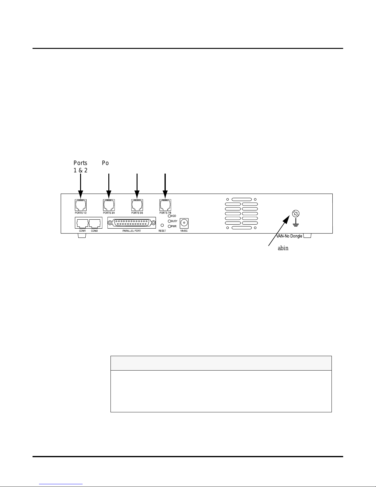
Figure 2: Back View of the VANGARD Mail Cabinet
When you are installing a card in the cabinet to expand your Voice Mail System, you need to keep
in mind the foll ow ing:
● A 2-port card in the f irst pos ition h as a singl e conne ctor, supports ports 1and 2, and s kips p orts
3 and 4.
● A 4-port card in the first position has two connectors and supports ports 1 through 4.
● A 2-port card in the sec ond posit ion has a sin gle conn ector, supports 5 and 6, and skips ports 7
and 8.
● A 4-port card in the second position supports ports 5 through 8.
WARNING
Do not turn off the Voice Mail without firs t shutting it dow n. If you do not shut down
first, you may corrupt the Voice Mail database when you turn it off.
Use standard static precautions when handli ng cards. Follow these steps exactly as
stated. Fa ilure to do so may result in damage the motherboard or port card.
VAN-No Dongle
Ports
1 & 2
Ports
3 & 4
Ports
5 & 6
Ports
7 & 8
COM1
Note: Your cabinet may not have
the Ground Stud shown in
this Figure.
Page 17
Installing the Voice Mail Hardware
Increasing the Number of Voice Mail Ports
Chapt er 2: Install ing the Voice Mail VANG ARD Mail/i-Series Quick Setup Guide ◆ 9
To instal l analog po r t card(s) to increase the number of Voice Mail ports:
1. If this is a new syst em, skip this step and go to ste p 2. If you ha ve an existing VANGARD
Mail System, you must shut down the Voice Mail before you install any cards:
■ From the Main Men u, select SD.
■ Press Y at the prompt asking if you are sure you want to shut down the system.
■ If you have a software version lower than 9.08, wait 20 seconds before disconn ecting
power. Otherwise, you may corrupt the Voice Mail database.
■ Disconnect the external power supply to turn off system power.
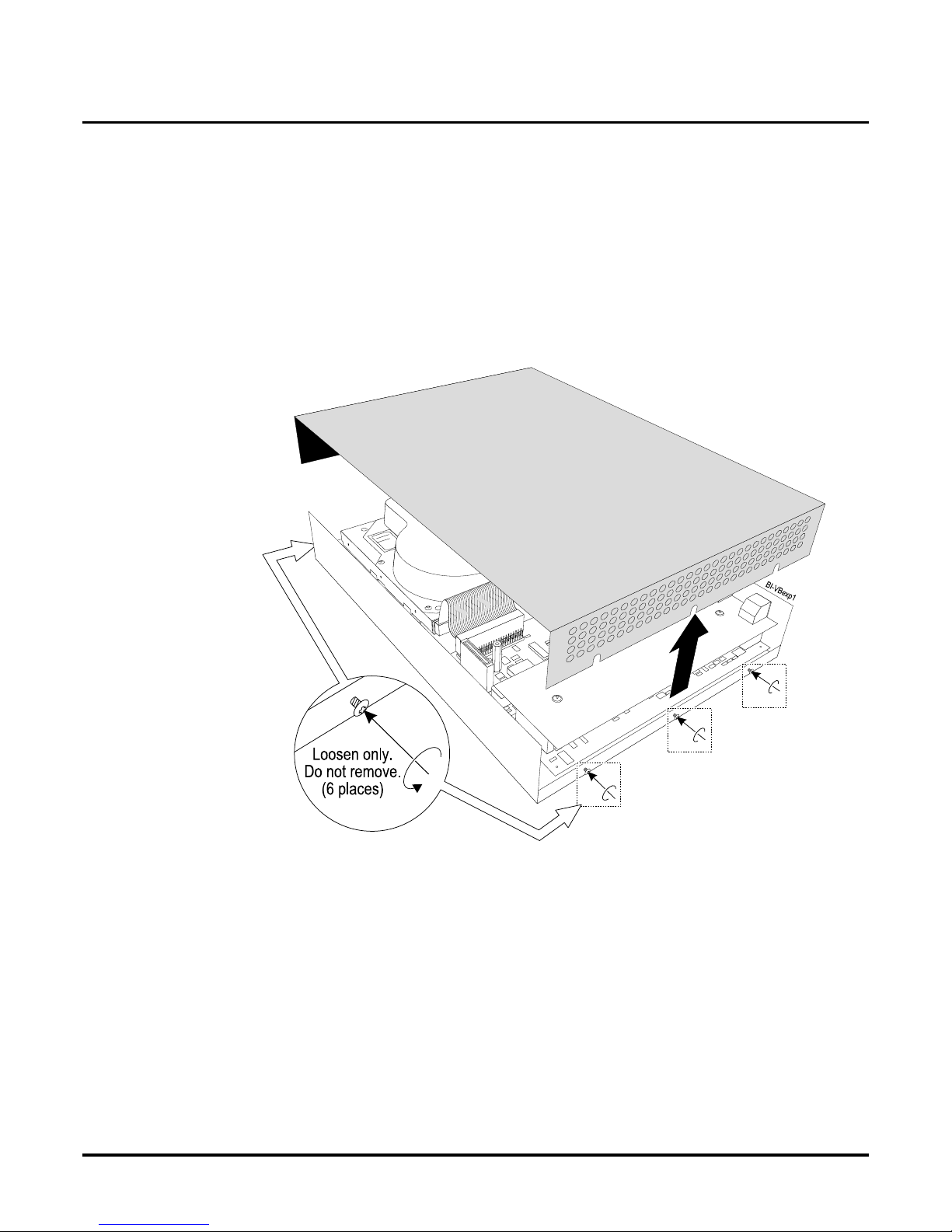
2. Use a screwdriver to loosen the six screws that secure the co ver to the cabinet, as shown
below.
Figure 3: Removing the Cabinet Cover
3. Remove the cabinet cover.
Page 18
Installing the Voice Mail Hardware
Increasing the Number of Voice Mail Ports
10 ◆ VANGARD Mail/i-Series Quick Setup Guide Chapter 2: Installing the Voice Mail
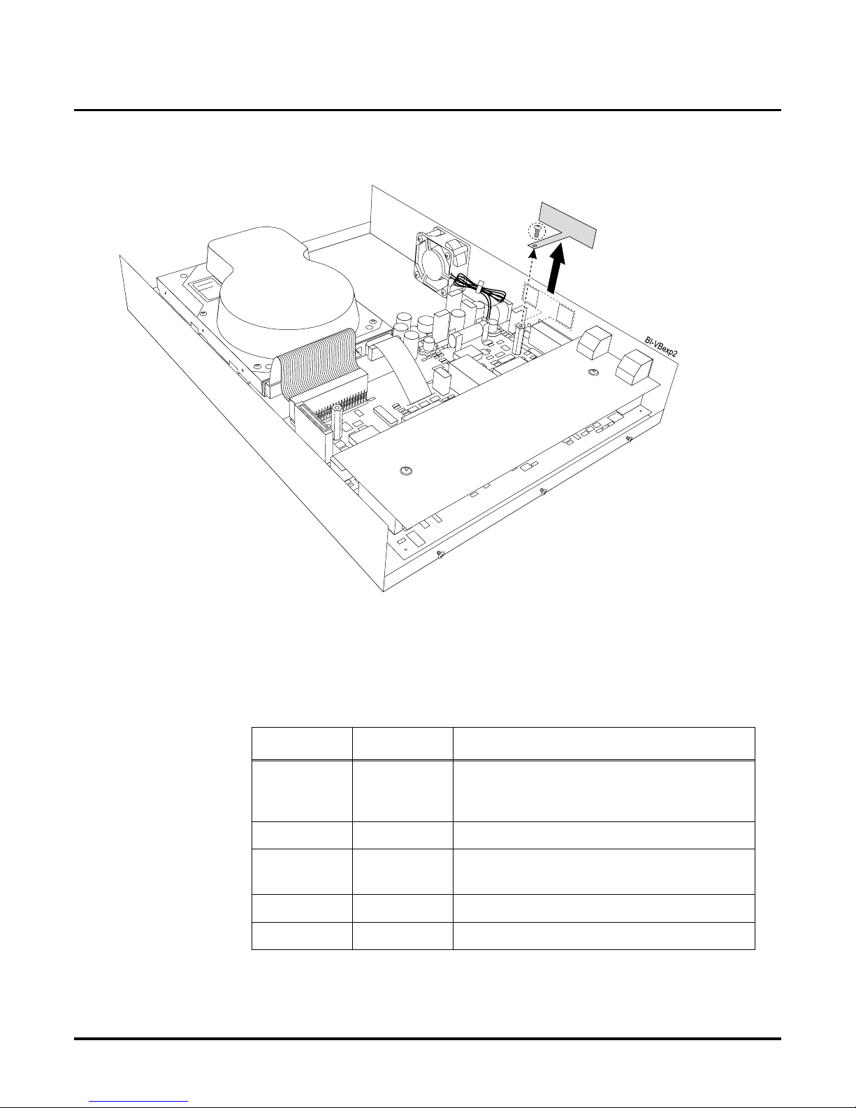
4. Remove the scre w from t he bracket (if pr esen t), and remov e the bracket fro m the standof f (see
the illustration below).
Figure 4: Removing the Bracket from the Standoff
5. In the table belo w, follow only th e instruc tio ns that apply to bo th your current numbe r of port s
(From column) and the desired numbe r of ports after the increase (To column).
For exampl e, to increase the number of available ports from 4 to 8, you would insert another
4-port card.
From To Instructions
2 4 Insert a 2-port card. or
Remove the e xisting 2-port c ard, and replace with
a 4-port ca rd.
2 6 Insert a 4-port card.
2 8 Remove the 2-port card, and insert two 4-port
cards.
4 6 Insert a 2-port card.
4 8 Insert another 4-port card.
Page 19

Installing the Voice Mail Hardware
Increasing the Number of Voice Mail Ports
Chapt er 2: Install ing the Voice Mail VANGARD Mail/i-Series Quick Setup Guide ◆ 11
6. W ith the car d h eld at an angle as shown in Figure 5, mak e sure that the RJ conn ectors are
inserted in the openings marked for Ports on the cabinet. Figure 5 shows installing a 4-Port
card into sl ot 2 s o the RJ connectors should be inserted in the openings marked Ports 5/6 and
Ports 7/8.
Figure 5: Inserting the RJ Connectors into Ports 5/6 and Ports 7/8
7. Lower the c ard into posi tio n, maki ng sure that the hole in the in the ca rd lines up with the ho le
in the standoff as shown in the illustration on the next page.
If the hole does not line up, re peat step 6 above, making sure that the RJ connect ors are
inserted prope rly through the openings.
WARNING
Follow these steps e xactly as stated. F ailure to do so may result in damage to J11 on
cabinet 17770 (or J7 on ca binet 17770A) on the motherboard.
WARNING
It is very important to insert the card so that the holes line up properly. Failure to do so
may permanently damage the card by flexing it when you apply pressure to the top of
the car d .
Page 20

Installing the Voice Mail Hardware
Increasing the Number of Voice Mail Ports
12 ◆ VANGARD Mail/i-Series Quick Setup Guide Chapter 2: Installing the Voice Mail
8. Push down on the port card’s hole to seat th e card firmly in the cabinet, as shown in the following illus tr a tion.
Figure 6: Seating the Card Firmly in the Cabinet
9. Secure th e ca r d w i th two screw s . Do no t ove r- ti g hten the s e s cr ew s .
10. Repeat steps 4 through 9 for each card that you are installing.
11. Replace the cabinet cover.
12. Tighten the screws loos ened in step 2 to secure the co ver.
13. If this is a new system, go to “Placing the Voice Mail in the Proper Location” on page 17. If
this is not a new installation, go to “Installing a Ferrite Bead on Each Line Cord” on page 22.
Installing Digital Port Cards
Each digital port card (P/N 17774ADIG) has 2 connectors and pro vides 4 ports. Each connector on
a port card provides 2 Voice Mail ports. See Figure 7.
Your digital VANGARD Mail System supports up to 8 ports .
If you have a 4-Port digital VANGARD Mail System, you can expand it with 4 additional ports.
Availability: VANGARD Mail with software version 10.06 or higher . Also requires
VANGARD Mail Cabinet P/N 17770A.
V
A
N
-
V
B
ex
p4
Align holes
Voice
Board
For cabinet 17770,
J11 and J1
should mate.
For cabinet 17770A,
J7 and J1
should mate.
Page 21

Installing the Voice Mail Hardware
Increasing the Number of Voice Mail Ports
Chapt er 2: Install ing the Voice Mail VANGARD Mail/i-Series Quick Setup Guide ◆ 13
Figure 7: VANGARD Digital P ort Card
See Figure 8 for a layout of the cabinet.
Figure 8: Back View of the VANGARD Mail Cabinet
Note: The VANGARD Mail Cabinet (P/N 1 7770A) supports either the digital port cards or the ana-
log port cards (P/N 17772 A and 17774A). However, you cannot install a digital and an
analog port card in the same sys t em .
To instal l digital port card(s) to increase the number of Voice Mail ports:
1. If this is a new syst em, skip this step and go to ste p 2. If you ha ve an existing VANGARD
Mail System, you must shut down the Voice Mail before you install any cards:
■ From the Main Men u, select SD.
■ Press Y at the prompt asking if you are sure you want to shut down the system.
■ Disconnect the external power supply to turn off system power.
WARNING
Do not turn off the Voice Mail without firs t shutting it dow n. If you do not shut down
first, you may corrupt the Voice Mail database when you turn it off.
Use standard static precautions when handli ng cards. Follow these steps exactly as
stated. Fa ilure to do so may result in damage the motherboard or port card.
Port Connector
Port Connector
Van-dig-card-01
VAN-No Dongle
Ports
1 & 2
Ports
3 & 4
Ports
5 & 6
Ports
7 & 8
COM1
Page 22

Installing the Voice Mail Hardware
Increasing the Number of Voice Mail Ports
14 ◆ VANGARD Mail/i-Series Quick Setup Guide Chapter 2: Installing the Voice Mail
2. Use a screwdriver to loosen the six screws that secure the cover to the cabinet. See Figure 9.
Figure 9: Removing the Cabinet Cover
3. Remove the cabinet cover.
4. If you have an existing VANGARD Mail with analog port cards, you must remove the m
before you install any digital cards.
If you are installing a card in slot 2, remove the screw from the bracket (if present), and
remove the bra cket from the standof f (s ee the illustration below).
Figure 10: Removing the Bracket from the Standoff
Page 23

Installing the Voice Mail Hardware
Increasing the Number of Voice Mail Ports
Chapt er 2: Install ing the Voice Mail VANGARD Mail/i-Series Quick Setup Guide ◆ 15
5. W ith the car d h eld at an angle as shown in Figure 11, make sure that the RJ connectors are
inserted in the openings marked for Ports on the cabinet. Figure 11 shows installi ng a card
into slot 2 so the RJ c onnect ors s hould be inse rte d in the opening s ma rked Po rts 5/6 and Ports
7/8.
Figure 11: Inserting the RJ Connectors into Ports 5/6 and Ports 7/8
6. Lower the c ard into posi tio n, maki ng sure that the hole in the in the ca rd lines up with the ho le
in the standoff as shown in the illustration on the next page.
If the hole does not line up, repeat step 5, making sure that the RJ connectors are inse rted
properly thro ugh the openings.
WARNING
Follow these steps exactly as stated. Failure to do so may result in damage to J7 on the
motherboard.
WARNING
It is very important to insert the card so that the holes line up properly. Failure to do so
may permanently damage the card by flexing it when you apply pressure to the top of
the car d .
Page 24

Installing the Voice Mail Hardware
Increasing the Number of Voice Mail Ports
16 ◆ VANGARD Mail/i-Series Quick Setup Guide Chapter 2: Installing the Voice Mail
7. Push down on the port card’s hole to seat th e card firmly in the cabinet, as shown in the following illus tr a tion.
Figure 12: Seating the Card Firmly in the Cabinet
8. Secure th e ca r d w i th two screw s . Do no t ove r- ti g hten the s e s cr ew s .
9. Repeat steps 4 through 9 for each card that you are installing.
10. Replace the cabinet cover.
11. Tighten the screws loos ened in step 2 to secure the co ver.
12. If this is a new system, go to “Placing the Voice Mail in the Proper Location” on page 17. If
this is not a new installation, go to “Installing a Ferrite Bead on Each Line Cord” on page 22.
V
A
N
-
D
i
gC
dex
p4
Align holes
Voice
Board
CN1 J7
and
should mate
Page 25

Installing the Voice Mail Hardware
Placing the Voice Mail in the Proper Location
Chapt er 2: Install ing the Voice Mail VANGARD Mail/i-Series Quick Setup Guide ◆ 17
Placing the Voice Mail in the Proper Location
Placing the Voice Mail in the Proper Location
Place the Voice Mail cabinet on a sturdy flat surface, or mount it on a wall. During pl acement, be
sure to observe all requirements listed in the Site Requirements.
Wall-Mounting the Voice Mail
Before you can mount the cabinet on the wall, you will need the following tools and materials:
● Phillips-head scre wdriver
● dry-wall screws
● center-hole punch, nail, or other pointed tool
● tape
● hammer
● paper wall-mounting template from the VANGARD Mail shipping box
To mount the VANGARD Mail on the wall:
1. Tape the paper template at the desired location on the wall.
Note: The area for mount ing sho uld be spacio us and fr ee of obs tru ctions t o allo w a irflo w aro und t he
cabinet.
2. Using a center-hole punch (or another pointed tool) and a hammer, strike 2 holes through the
paper templa te at the locations shown.
3. Remove the paper te mplate from the wall.
4. Screw the 2 screws into the holes you punched, until the heads of both screws are about 1/8”
from the wall surface.
5. Hold the Voice Mail cabinet, so that the bottom of the cabinet is facing the wall and the Port
Connectors are fa cing the floor.
6. Using the two ke yhole-shaped slots on the bottom of the cabinet, place the cabinet over the
screws until it touches the wall.
7. Carefully lower the cabinet into place.
CAUTION
Promote adequate airflow around the unit by making sure that the fan vent slots and
ventilation holes on each sid e of the cabinet are clear of obstructions.
Page 26

Installing the Voice Mail Hardware
Placing the Voice Mail in the Proper Location
18 ◆ VANGARD Mail/i-Series Quick Setup Guide Chapter 2: Installing the Voice Mail
Grounding VANGARD Mail
If you have cabinet 17770A, you need will need to ground the Voice Mail. See Figure 13 for location of the ground lug.
Figure 13: Locat i on o f the Ground Lug on the Ca bi net
To ground the VANGARD Mail System:
● Connect a 14 AWG ground wire from the ground lug on the cabinet to a verified earth ground.
VAN-Ground Stud-02
14 AWG
to Earth Ground
COM1
Page 27
Installing the Voice Mail Hardware
Connecting a Laptop to the Voice Mail
Chapt er 2: Install ing the Voice Mail VANGARD Mail/i-Series Quick Setup Guide ◆ 19
Connecting a Laptop to the Voice Mail
Connecting a Laptop to the Voice Mail
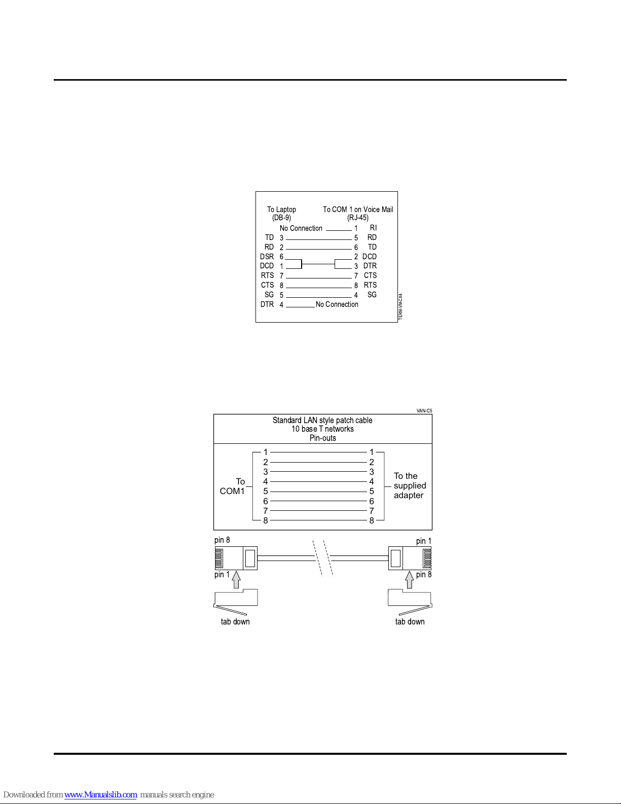
To connect a laptop computer to COM 1 on the VANGARD, you should use the VANGARD Mail
null modem adapter for s erial communication (P/N 17777). This adapter comes with the VANGARD Mail and is an RJ-45 (8 conductor) to DB-9 m odular adapter. See Figure 14 for pin-outs of
the null modem adapter. To use the null modem adapter, you must supply a standard LAN style
patch cable shown in Figure 15.
Figure 14: Pin-outs of the VANGARD Null Modem Adapter (P/N 17777)
To connect the laptop computer to the VAN GARD Mail:
1. Use a standard, straight-through, LAN style pa tch cable. Make sure the ca ble is wired as
shown in Figure 17.
Figure 15: Requ ir e d P in -out s for St andard LAN Style Patch Ca bl e
TERM-VM-CX4
No Connection
3
2
6
1
7
8
5
4
TD
RD
DSR
DCD
RTS
CTS
SG
DTR
RI
RD
TD
DCD
DTR
CTS
RTS
SG
1
5
6
2
3
7
8
4
No Connection
To Laptop
(DB-9)
To COM 1on Voice Mail
(RJ-45)
Standard LAN style patch cable
10 base T networks
Pin-outs
1
2
3
4
5
6
7
8
1
2
3
4
5
6
7
8
To
COM1
To the
supplied
adapter
VAN-C5
tab down
pin 1
pin 8
pin 1
pin 8
tab down
Page 28

Installing the Voice Mail Hardware
Connecting a Laptop to the Vo i ce Mail
20 ◆ VANGARD Mail/i-Series Quick Setup Guide Chapter 2: Installing the Voice Mail
2. Plug one end of the standard LAN style patch cable into COM1 on the VANGARD Mail as
shown in Figure 16.
3. Plug the oth er e nd of the cable into the RJ-45 connector on the VANGARD Mail null modem
adapter (P/N 17777).
4. Plug the DB9 connector on the ada pter into the COM port on the laptop c omputer.
5. Sec u r e th e ad a pt er in place w i th th e at tached sc rew s.
.
Figure 16: Connecting a Laptop Computer to VANGARD Mail
WARNING
Make sure you do not accidently plug the line cords for th e phone
system into COM1 or CO M2 on the Voice Mail. This connection may
permanentl y damage the COM port.
VAN-C11
LAN style patch cable
(to be supplied by customer)
COM1
CONSOLE / COM2
(reserved for HOSTKEY use)
supplied
adapter
Voice Mail
Ports
1&2
Voice Mail
Ports
3&4
Voice Mail
Ports
5&6
Voice Mail
Ports
7&8
Ground
Stud
Page 29

Installing the Voice Mail Hardware
Connecting a Laptop to the Voice Mail
Chapt er 2: Install ing the Voice Mail VANGARD Mail/i-Series Quick Setup Guide ◆ 21
Setting the Communication Parameters
The Voice Mail is shipped to you with an internal modem . Your calling modem should be set to
2400 baud, 8 data bits , no pari ty, and 1 stop bit (2400, 8, N, 1). With software version 9.08 and
higher, the modem mailbox number is 862 at default. (At defaul t, you can reach the modem b y dialing # 8 6 2 at the main greeting.)
To set the communication parameters:
1. Use a standard communications software progra m, such as Procomm Plus, to set to 9600
baud, 8 data bits, no parity, and 1 stop bit (9600, 8, N, 1). The terminal emulation should be
VT100.
2. If you are using W indows HyperTermina l:
In Port Settings set Flow Control to None. After changing parameters in Hype rTerminal, you
must break your connection (Disconnect) and re -establish your connection (Call).
3. When you are finished connecting the laptop, go the next section, Connect Voice Mail to the
Telephone System.
To return the Voice Mail’s COM1 or Modem/COM2 to the default setting:
1. Log into the System Admin Mailbox.
2. Enter the se cur ity code, if required.
3. Enter SA to access the System Administrator Options.
4. Enter C1 for COM1 or C2 for Modem/COM2.
The system responds wit h the Ready prompt. Ready co nf irms tha t the se lect ed COM has been
reset to the defau lt setti n g .
(C1 and C2 are service options. They are not listed in the SA help menu.)
5. Hang up.
Page 30

Connectin g the Voice Mail to a Phone System
Installing Ferrite Bead(s)
22 ◆ VANGARD Mail/i-Series Quick Setup Guide Chapter 2: Installing the Voice Mail
Installin g Fer rite Bead(s )Connecting the Voice Mail to a P hone System
Installing a Ferrite Bead on Each Line Cord
On each line cord in your Voice Mail cabinet, you must install one ferrite bead. Ferrite bead installation keeps the device in compliance with FCC P art 15 Regula tions by controlling the Electr oMagnetic Interference (EMI) produced by your system. Without this control, the radiation from
electric al and magnetic fields could cause your equipm ent to malfunction, due to interference with
signal transmis s i on or rece p tion.
If your Voice Mail was shippe d to you wit h a 2-p ort ana log card , the VANGARD Mail box contains
one ferrite bead. But if your Voice Mail was shipped with a 4-port car d, the box co ntains two ferri te
beads. Similarly, the box for each 2-port expansion card contains one bead and for each 4-port
expansion card contains two beads.
To instal l a bead on the line cord for Ports 1 and 2:
1. Pry open the ferrite bead, as shown in the following illustration.
Figure 17: Prying Open the Ferrite Bead
2. With the ferrite bead held at least 6 inches from the end of the li ne cord, loop the cord once
through bead, as shown in the illustration below.
Figure 18: Looping the Line Cord through the Ferrite Bead
3. Close th e f er rite bead.
To install beads on line cords for other ports:
● Perform Steps 1through 2 above for each remaining line cord.
6"
Line cord
To V oice Mail
Page 31
Connecting the Voice Mail to a Phone System
Connecting Analog VANGARD Mail Ports
Chapt er 2: Install ing the Voice Mail VANGARD Mail/i-Series Quick Setup Guide ◆ 23
Connecting Analog VANGARD Mail Ports
Connecting Analog VANGARD Mail Ports to the i-Series
To connect Voice Mail ports to an i-series phone system:
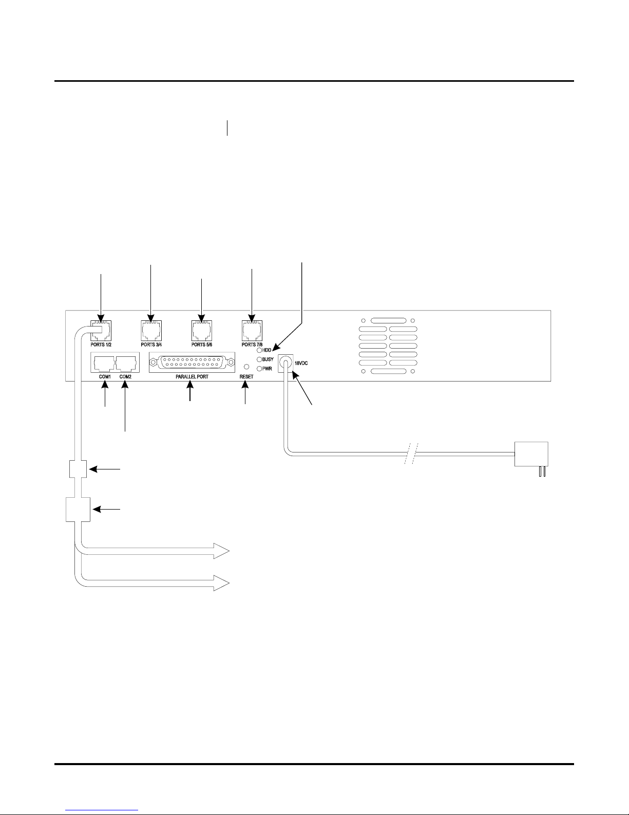
1. Refer to the illus tration below:
Plug one end of the line cord (where the ferrite bead is connecte d) into the Ports 1/2 connector. Plug the other end of the cord into an RJ14-to-RJ11 adaptor or RJ14 jack.
Be sure you have already installed a fe rrite bead on this line cord. If you haven’t, see “Install-
ing a Ferrite Bead on Each Li ne Cord” on page 22.
Figure 19: Connecting Analog Voice Mail Ports 1 and 2 to the Phone System
2. Plug L1 (or the RD/GR pair) into an an alog station port.
L1 connects to the lower-numbered port in the port connector.
3. Repeat steps 1 and 2 for each pair of analog Voice Mail ports, us ing the appropriate Port s
connector on the back of the cabinet.
Be sure that you remember the slot where you instal led a 2-port or 4-port card. You need to
keep in mind the f ollowing:
■ A 2-port card in the first position supports ports 1and 2, and skips ports 3 and 4.
■ A 4-port card in the first position supports ports 1 through 4.
■ A 2-port card in the second position supports 5 and 6, and skips ports 7 and 8.
■ A 4-port card in the second position supports ports 5 through 8.
Availability: Analog VANGARD Mail version 9.08 or higher.
Ports
1 & 2
Ports
3 & 4
Ports
5 & 6
Ports
7 & 8
Status
LEDs
AC Power
Connector
AC Power Cord
External
Power Supply
Reset
Printer
Port
CONSOLE / COM2
(reserved for HOSTKEY use)
COM
1
Ferrite Bead
RJ14 to RJ11 adapter
or RJ14 jack
L1
L2
To Analog Port or OPX 1
To Analog Port or OPX 2
Page 32

Connectin g the Voice Mail to a Phone System
Connecting Analog VANGARD Mail Ports
24 ◆ VANGARD Mail/i-Series Quick Setup Guide Chapter 2: Installing the Voice Mail
4. Plug a surge protector into the dedi ca ted and grounded electrical outlet.
5. Pl ug th e AC adap ter into th e surge prot ector.
6. Plug the connect or from the AC adapte r into the 18VDC jack on the Voice Mail cabinet.
Both the gree n PWR light and the yellow BUSY light will be lit. As soon as the BUSY light
goes out, the system is rea dy for use.
7. Go to the section, “Initializing the Voice Mail for Your Phone System” on page 33.
Page 33

Connecting the Voice Mail to a Phone System
Connecting Digital VANGARD Mail Ports
Chapt er 2: Install ing the Voice Mail VANGARD Mail/i-Series Quick Setup Guide ◆ 25
Connecting Digital VANGARD Mail Ports
Connecting Digital VANGARD Ma il Ports to the i-Series
To connect digital Voice Mail ports to the an i-series phone system:
1. Refer to the illus tration below:
Plug the short end of the line cord (where the ferrite bead is connected) is connected Ports 1/
2 connector on the back of the Voice Mail. Plug the other end of the cord into a Voice Mail
Interface Unit. Be sure you have installed the f errite bead on this line cord.If you have n ’t, see
“Installing a Fer r ite Bead on Each Line Cord” on page 22.
Figure 20: Co nnecti ng Digital Voice Mai l Ports to an I-Series Phone Syste m
2. Plug the other end into a 625 modular jack assembly.
3. Connect one-pair 24 AWG station cable to an odd-numbered s t ation por t in th e i- S eries
telephone system.When you program the phone system for Voice Mail, use this odd-numbered port and the next even port. (See the in st allation manual for the phone system for com-
plete instructions on connecting an i-Series phone system.)
Availability: Digital VANGARD Mail with version 10.06 or higher.
WARNING
Make sure you do not accidently plug the line cords for th e phone
system into COM1 or CO M2 on the Voice Mail. This connection may
permanentl y damage the COM port.
VAN-C8
Voice Mail
Ports
1&2
Voice Mail
Ports
3&4
Voice Mail
Ports
5&6
Voice Mail
Ports
7&8
COM
1
CONSOLE / COM2
(reserved for HOSTKEY use)
Reset
Status
LEDS
AC
Adapter
AC Power Cord
AC Power
Connector
Ferrite Bead
To Odd-Numbered
Digital Extension
Circuit
Ground
Stud
BLK
YEL
GRN
RED
625 Modular Jack
Page 34

Connectin g the Voice Mail to a Phone System
Connecting Digital VANGARD Mail Ports
26 ◆ VANGARD Mail/i-Series Quick Setup Guide Chapter 2: Installing the Voice Mail
4. Te rminate the WHT/BLU - BLU/WHITE leads to the RED and GRN lugs in a 625 modular
jack assembly.
5. Repeat steps 1 through 4 for each pair of digital Voice Mail ports that you are connecting.
6. Plug a surge protector into the dedi ca ted and grounded electrical outlet.
7. Pl ug th e AC adap ter into th e surge prot ector.
8. Plug the connect or from the AC adapte r into the 18VDC jack on the Voice Mail
Both the green PWR li ght and yellow BUSY light will be lit.
As soon as the Busy light goes out, the system is ready for use.
9. Go to the section, “Initializing the Voice Mail for Your Phone System” on page 33.
WARNING
Make sure you do not accidently plug the line cords for th e phone
system into COM1 or CO M2 on the Voice Mail. This connection may
permanentl y damage the COM port.
Page 35

Overview
Chapter 3: Phone Programming VANGARD Mail/i-Series Quick Setup Guide ◆ 27
Chapter 3:
Phone System
Programming
Overvi ew
Overview
Your phone system requires specific entries in several prog rams so that it integrates correctly with
the Voice Mail. In addition, the phone syste m may need to have a piece of specific equipm ent or a
certa in so ft w ar e level in order f or it to op er a te corre ct ly wi t h th e Voice Mail.
This section tells you if need any s pecial equipmen t and the specific programs you need to configure in your phone syste m so that it integrates with VANGARD Mail.
Page 36

Phone System Programming
For i-Series (28i/124i/384i/704i)
28 ◆ VANGARD Mail/i-Series Quick Sertup Guide Chapte r 3: Phone Program m ing
For i-Series (28i /124i/384i/704i)Phone System Programming
Voice Mail Required Hardware and Software
Phone System Hardware and Software Requirements
Hardware
Each analog Voice Mail port requires one analog port on the ASTU card.
For each pair of digital Voice Mail ports, you will connect to one digital port in the phone sys-
tem. You connect the Voice Mail to an odd-num bered digital sta tion port. Program the phone system for Voice Mail using this odd-num bered port and the next even port.
Software (for integrating with the Analog VANGARD Mail)
Analog Voice Mail is supported in al l i- S eries software versions.
Software (for integrating with the Digital VANGARD Mail)
The 28i/124i requires phone system software version 6.00. 08 or higher.
All versions of the 124ie/704i support the integration.
The 384i requires pho ne s ys tem software 4.00.30 or higher .
All versions of the Commonized S of tware
Required Phone System Programming
➻ 0004 - Automatic Extension Circuit Type
(Use Phone Programming. Applies to 28i/124i commonized, 124ie/704i and 384i)
Make sure that you have alread y installed the Voice Mail Port Cards and connected the VANGARD to the phone system before you use this program.
Run program 0004 to automatically set up extension circuit types.
Note: Running 0004 after the system is set up may require that you re-p rogram certain
devices (such as DSS Consoles and DCI’s).
➻ 0005 - Extension Circuit Type (Whenever possible, use 0004)
(Use Phone Programming. Applies to 28i/124i commonized, 124ie/704i and 384i)
Assign circuit type 3 to analog Voice Mail ports.
Assign circuit 9, order 2 to digital Voice Mail ports. (Re memb er to program both the oddnumbered port and the next consecuti ve even port reserved by th e syst em .)
Note: Entering circuit type using 0005 may require a manual entry in 1001. [In 100 1 - Basic
Extension Port Setup (Part A), Item 1: Telephone Signaling Type, enter 1 for DTMF.]
➻ 0303 - DTMF and Dial Tone Detection Circuit Setup
(Applies to 384i /704i Only)
Assign at least one CDTU block for DTMF reception (type 1).
Will ring after the DIL Call Waiting time (Program 0405 Item 62).
Availability: All analog VANGARD Mail versions
Digital VANGARD Mail with version 10.06 or higher.
IMPORTANT
Before you program the phon e system, make sure that you have performed all steps in
Chapter 2: Installing the Voice Mail (beginning on page 5). This simplifies programming the phone system . Specifically, make sure that you have installed the Voice Mail
Port Cards and connected the VANGARD to the phone system.
Page 37

Phone System Programming
For i-Series (28i/124i/384i/704i)
Chapter 3: Phone Programming VANGARD Mail/i-Series Quick Setup Guide ◆ 29
➻ 1001 - Basic Extension Port Setup (part A), Item 5: Terminal Typ e
(Use Phone Programming. Applies to Commonized Software and for any i-se ries with the
digital VANGARD)
Set all station ports used for Voice Mail as type 1. (Enables DTMF dialing into Voice Mail
from Keysets .)
For Digita l VANGARD Ports: remember to program both th e odd-numbere d port and the ne xt
consecutive even port r eserved by the system.
➻ 1003 - Extension (Department) Groups
Put all the Voice Mail ports in a De partment Group (typically the last available group. For 28i/
124i, use group 8; For 384i/704i, use group 32), and assign an order number (1, 2, 3, etc.)
For Digita l VANGARD Ports: remember to program both th e odd-numbere d port and the ne xt
consecutive even port r eserved by the system.
This group is used to distribute calls directed to the Voice Mail. It also allows DILs to the
Voice Mail to ring other Voice Mail ports when the DIL ’s assigned port is busy.
➻ 1005 - Class of Service
Assign all of the Voice Mail ports with an unused Cla ss of Se rvice (t ypi cally, the last av a ilabl e
COS. For 28i/124i, use COS 8. For 384i/704i, use COS 15).
For Digita l VANGARD Ports: remember to program both th e odd-numbere d port and the ne xt
consecutive even port r eserved by the system.
➻ 0410 - Extension (Department) Group Options, Item 3: Voice Mail Group
Enter 1 for the Voice Mail group (the Group you assigned in Program 1003)
Designate which Department Group is to be assigned as a Voice Mail Group.
➻ Program 0419 - Class of Ser vice Options (Part B), Item 26: Message Wai t Dialtone
Enter 0 (zero) for the Class of Service assigned to the Voice Mail ports.
(Stutter dial tone on a Voice Mail port causes Message Wait Lamping and transfer problems.)
➻ 0516 - Voice Mail Master Number
Assign an e xtens ion number and n ame fo r the Voice Mail Master Number. Be sure the number
you select doe s not c orres pond to a n inst alle d e xtens ion or fe ature. Con sider pickin g a n umber
that is outside the normal extensi on numbering range (e.g., 600). Do not se lect a number that
begins with 1, 8 or 9.
➻ 1017 - Voice Mail Port Assignment
(Applies to 28i/124i with software versions 5.07 and lower, and 384i with software version
3.08.00 or lo wer)
(F or ALL other i-serie s software vers ion s, use Program 1003)
Assign single line (ASTU PCB) ports as Voice Ma il po r ts. The sy ste m al low s u p to 16 Voice
Mail ports.
Optional Phone System Programming
➻ 0401 - Tenant Group Options, Part A, Item 18: SLT Answering Mode
Enter 1 for this option to enable Conv ersation Record.
➻ 0401 - Tenant Group Options, Part A, Item 23: DIL Call Waiting
If setting up Immediate Voice Mail Overflow , enter 0. If setting up Delayed Voice Mail Overflow, enter 1.
➻ 0405 - System Timers (Part A), Item 62: DIL No Answer Recall Time
If setting up Delaye d Voice Mail Overflow, enter a timer value greate r than 0. Overflow will
occur after this interval (provided the other related programming is correct). If setting up
Immediate Voice Mail Overflow, enter 0.
➻ 0405 - System Timers (Part A), Item 65: Recor d Alert Tone Interval Time
Set the interval between Voice Mail Conv ersation Record aler ts. The alert is two short beeps
followed by a pro g rammabl e in t erval of sil en c e.
Page 38

Phone System Programming
For i-Series (28i/124i/384i/704i)
30 ◆ VANGARD Mail/i-Series Quick Sertup Guide Chapte r 3: Phone Program m ing
➻ 0406 - COS Options, Item 57: Continued Dialing
Enable Continued Dialing (1) for all extensions that will dial Voice Mail features.
➻ 0901 - Basic Trunk Port Setup (Part A), Items 14-17; Trunk Service Type
Assign Service Type 4 to each t runk you want to ring into Voice Mail as a Direct Inw ard L ine
(DIL).
➻ 0909 - Extension Ring Group Assignment
To enable Voice Mail Overflow, assign selected ext ensions to a Ring Group th at will ring for
unanswered DILs to Voice Mail ports. Enter 1 to enable overflow ringing.
➻ 0910 - Trunk Ring Group Assignment
To enable Voice Mail Overf low, assign the Voice Mail DILs to the Ring Group specified in
program 0909 abov e. This allows calls on the DILs to ring other extensions when all VM
ports are busy.
➻ 0917 DIL Assignment
Assign a Voice Mail port as the DIL destination for each tru nk that should directl y ring into
Voice Mail. (Requires Trunk Service Type 4 in 0901.) If all Voic e Mail ports are in the same
unique Extension (Department) Group (see Program 1003 on page 29), the DIL will ring
another Voice Mail port if its assigned port is busy.
➻ 1005 - Class of Service
Assign a Cla ss of Service (1-15) to an extension.
➻ 1006 - Programming Function Keys
Assign a Voice Mail key to an extension (code 1059 plus extension num ber).
(Optional) Assign a Voice Mail Record key to an extension code (1060).
(Optional) Assign a Personal Answering Machine Emulation key (code 1072).
➻ 1027 - Fixed Call Forwar d ing S etup
Transf erred, DIL and DID calls can forward to Voice Mail using this progra m.
For an extension port, assign the Fixed Call Forwarding Type (0-4) and the des tination ext ension port (first Voice Mail extension port.) Available types are:
0 = Fixed Call Forw arding off
1 = Fixed Call Forwarding with Both Ringing (do not use for Voi ce Mail ports)
2 = Fixed Call Forwarding when Unanswered
3 = Fixed Call Forw arding Immediate
4 = Fixed Call Forwarding when Busy or Not Answered
(Prior to 384i system software 3.04, type 4 was not available)
For DS-Series
Page 39

Overview
Chapter 4: Voice Mail Programming VANGARD Mail/i-Series Quick S etup Guide ◆ 31
Chapter 4:
Programming
the Voice Mail
Overvi ew
Overview
This chapter provi des in struc tions for programmi ng the basic Automated Attendan t and a fe w other
important features. In a few easy steps you will have the basic VANGARD Mail customized for
your communica tion needs. Specifically, you find information about:
1. Initializing the Voice Mail for Your Phone System (beginning on page 33)
2. Required Progr ammi ng for the Voice Mail Ports (begi nning on page 34)
● Installing Ports (page 34)
● Removing Ports from Service (page 34)
3. Default Setup for thei-Seri es (page 35)
4. Shutting Down the Voice Mail (page 36)
● From the Main Menu (page 36)
● Using the Rese t S w itch (page 36)
5. Testing the Voice Mail Operation (page 37)
6. Basic Voice Mail Programming (beginning on pa ge 38
● Modifying the Time and Date (page 38)
● Assigning Extensi ons to VANGARD Mail Ports (page 39)
● Checking the Def ault Automated Attendant (page 40)
● Assigning Answering Schedule Tables to Ports or Trunks (page 43)
● Completing the AST Worksheet (page 45)
● Creating and/or Customizing Call Routing Mailboxes (page 47)
● Programming the ASTs (page 48)
Page 40

Overview
32 ◆ VANGARD Mail/i-Series Quick Setup Guide Chapter 4: Voice Mail Programmin g
● Modifying the Welcome Messages (page 49)
● Modifying the Dial Action Tables (page 50)
● Modifying the Instruction Menus (page 54)
● Recording Names for Subscriber Mailboxes (page 55)
● Customizing the Features for the Internal Modem (page 56)
● Selecting the Active Language (page 57)
When you are finished with this chapter, use Chapter 3, Programming, in the VANGARD System
Guide (P/N 17770INS10 or high er) to perform any other program mi ng that you may need.
Page 41

Initializing the Voice Mail
Installing the Phone System
Chapter 4: Voice Mail Programming VANGARD Mail/i-Series Quick Setup Guide ◆ 33
Installing the Phone SystemInitializ ing th e Voice Ma il
Initializing the Voice Mail for Your Phone System
Installing the Phone System
If this is a new installation, you m ust specify the i-series in Voic e Mail programming as the phone
system that you actually connected to the VANGARD. If this is not a new installation, a nd you simply install ed additional port cards, skip this part and go to “Requi red Programming for the Voice
Mail Ports” on page 34.
To install the phone system in the Voice Mail:
1. Turn on the laptop or other computer, and access the communications software.
When the computer is communicating with t h e Voice Mail, you will see the MAIN MENU ->
prompt.
2. At the MAIN MENU -> prompt. press IN and then Enter.
3. Enter the password (the default password is CTL), if requested and press Enter.
The Install Syst em Menu will be displa yed. Each phone syste m on this menu corre sponds to a
number in the column at the left.
Note: The Menu shown below is for softwa re ve rsions 9. 08. Lo wer ve rsions of s oftwar e do not ha v e
the DS2000 phone syste m listed on the INSTALL SYSTEM Menu.
4. Press 5 (t he number that corresponds t o the i-Series) as the phone system to be installed in the
Voice Mail.
5. Press Enter.
6. Follow the instructions on your Voice Mail screen.
For information about integrating the i-Series with the Voice Mail, see “Chapter 3: Phone Sys-
tem Programming” on pa ge 27.
This option is also available on the Database Management Menu. See
System Initialization (SI) and Power Down (DP) in “Using the
Options on the Database Manage ment Menu” in Chapter 3 of the VANGARD System Guide.
******* INSTALL SYSTEM Menu *******
Press command below,
then press Enter:
To Install the Voice Mail
System for:
1
2
3
4
5
6
7
90
91
92
93
94
e
ONYX VS/VSI/DS100/DS01
ONYX VS/VSI 24x72
ALLIANCE-S/ELECTRA PRO I PLUS
ALLIANCE-M/L
28i/124i
PORTRAIT 308/824
DS2000
To Install Voice Mail Ports only
To Install Voice Compression Rate only
To View Current Settings
Language Selections
Run Support Programs
Exit to MAIN Menu
Page 42

Required Programming for the Voice Mail Ports
Installing and Removing Ports from Service
34 ◆ VANGARD Mail/i-Series Quick Setup Guide Chapter 4: Voice Mail Programmin g
Installing and Removing Ports from ServiceRequired Programming for the Voice Mail Ports
Required Programming for the Voice Mail Ports
After you install a port card, you must install the Voice Mail ports in system software. You must
install the Voice Mail ports if this is a new installation or if you are just adding a port card.
You must also re move any Voice Mail ports that are not physically installed. This is required if
you do not use all of the ports that are av ailable on the port card. For example, if you are only
using ports 1 through 3, then you should remo ve port 4 from service. Be sure that Message Wait-
ing and Message Notification are on for at least one port (CU-Customize
➱ PO-Port
Options).
Installing Ports
To instal l the Voice Mail ports:
1. From the MAIN MENU - > pr ompt , s e l ect IN - Install System and then press Enter.
2. Enter the password (the default password is CTL), if requested and press Enter.
The Install System Menu will be displayed.
3. From the Install S y s tem Menu, select 90 - To Install Vo ice Mail Ports Only.
4. When you see Do you wish to change the number of ports? (Y/N), enter Y.
5. When you see Number of Voice Mail ports (1-8):
Enter the number of ports you added and Enter.
You program the VANGARD Mail based on Port Posit ion rather than the number of ports.
For exampl e, if you have a 2-port An analog VANGARD Mail and you are adding a 4-port
card in the second position, you must enter 8 ports in this step. You must then delete ports 3
and 4 from service, using the procedure be low.
Remember:
■ A 2-port card in the first position supports ports 1and 2, and skips ports 3 and 4.
■ A 4-port card in the first position supports ports 1 through 4.
■ A 2-port card in the second position supports 5 and 6, and skips ports 7 and 8.
■ A 4-port car in the second position supports ports 5 through 8.
6. After the ins tallation completes, type E and Enter to return to the Main Menu.
7. Fol low th e in s t r u ctions on the scre e n.
Removing Ports from Service
To rem ove the Voice Mail ports from service:
1. From the MAIN MENU -> prompt , select CU-Customize Database and then press Enter.
2. From the Customize Database Menu, select PO - Port Options.
3. Press Enter until you see the port you wish to remove from servic e. From the previous exam-
ple, you press Enter until you see, Port 3 - In Service (Y/N).
4. Type N and En ter.
5. From the previous example, when you see, Port 4 - In Service (Y/N).
6. Type N and En ter.
7. After the ins tallation completes, type E and Enter to return to the Main Menu.
8. Fol low th e in s t r u ctions on the scre e n .
Page 43

Default Setup for the Voice Mail
Mailbox Configuration with the i-Series
Chapter 4: Voice Mail Programming VANGARD Mail/i-Series Quick Setup Guide ◆ 35
Mailbox Configuration with thei-SeriesDefault Setup for the Vo ic e Mail
Mailbo x Configura tion
Once you initial ize the VANGARD for the i-Series, the Voice Mail database is set up with the following defa ult mailbox es. You can increase the default number of mailboxes to 200. In software
versions be low 9.08, the default number of mailboxes is 186. In software version 9.08 and higher,
the default number of mailboxes is 187. You can change mailboxes that are default ed as one type
to another type. However, if you change trunk mailbox es to some other type, it is recommended
that you keep one mailbox defined as a trunk mailbox.
Mailbox Type Default # of
Mailbox Type
Default Numbering of Mai lboxes
Announcement Mailbox 10 800-809
Call Routing Mailbox 17 810-814,
821-824,
831-834,
841-844
Distribution Mailbox 10 851-860
Future Delivery Mailbox 1 861
Guest Mailbox 8 819-820,
829-830,
839-840,
849-850
Message Center Mailbox 16 815-818,
825-828,
835-838,
845-848
Modem Mailbox 1
(with software
version 9.08
or higher)
862
(with software version 9.08 or
higher)
Subscriber Mailbox 72 301-372
Trunk Mailbox 52 001-052
Page 44

Default Setup for the Voice Mail
Shutting Down the Voice Mail
36 ◆ VANGARD Mail/i-Series Quick Setup Guide Chapter 4: Voice Mail Programmin g
Shutting Down the Voice Mail
Shutting Down the Voice Mail
Before you turn off power to the VANGARD, you must shut down the system. If you do not, you
may corrupt the Voice Mail database.
From the Main Menu
To shut down the Voice Mail:
1. From the MAIN MENU - > pr ompt , s e l ect SD and then press Enter.
2. Press Y at the prompt as king if you are sure you want to shut down the system.
3. If you have a software version lower than 9.08, wait 20 seconds after you see the pr omp t st ating that system shutdown is complete. If you have software version 9.08 or higher, you do not
need to wait 20 seconds; you can go immediate ly to step 4.
4. Turn off the system power by disconnecting the external power supply.
Using the Reset Switch
The Reset switc h (sho wn i n the ill ustra tion be lo w) i s locate d on t he panel of th e Voice Mail cabinet,
right behind the hole marked RESET. Pressing the Reset switch will reset the Voice Mail without
your performing a com plete shutdown. The VANGARD Mail reset is similar to the warm start you
will get after you press CTRL-ALT -DELET E on your computer. In addition, the reset will discon nect any calls in progress and stop all call-processi ng act ivity.
Press the Reset switch only when instructed to do so by NEC Technical Support.
Figure 21: Reset Switch
To reset the Voice Mail when instructed by NEC Technical Support:
● Insert a pointed object, such as a pa p er cl ip , in t o the RE S ET hole. The S ta t us LED s on th e
panel will blink.
Ports
1 & 2
Ports
3 & 4
Ports
5 & 6
Ports
7 & 8
Status
LEDs
HDD - Hard Drive Status (Red)
BUSY - Port Status (Yellow)
PWR - Power Status (Green)
COM
1
COM
2
Printer
Port
Reset
Switch
AC Power
Connector
Page 45

Testing the Voice Mail Operation
Chapter 4: Voice Mail Programming VANGARD Mail/i-Series Quick Setup Guide ◆ 37
Testin g the Voic e M ail Operation
Testing the Voice Mail
Once VANGARD Mail has been installe d and initialized, you should perform the following two
tests to check Voice Mail operation.
Test 1 (for the Automated Attendant):
1. Call into a trunk that you have assigned to VANGARD Mail.
2. Listen for: Thank you for calling. If you are calling from a Touch Tone phone, please dial
the extension number you wish to reach or dia l 0 f or assistance. If you ar e ca lling from a
rotary dial phone, please stay on the line for assistance.
Test 2 (for Voice Mail):
1. From the MAIN MENU - > pr ompt , s e l ect DI - Diagnostics and then press Enter.
2. Enter the password (the default password is CTL), if requested and press Enter.
3. Select PA - Port Activity and then press Enter.
4. At a Multibutton extension, press the Message Key.
5. Listen for: You have —messages (if you did not install a default Sec urity Code) or Please
enter your security code.
6. Repeat steps 4 and 5 until you see each Voice Mail port operating.
If you do not hear the stated voice prompts, check the equipment connections and the telephone
system programming for Voice Mail.
Page 46

Basic Voice Mail Programming
Modifying the Time and Date
38 ◆ VANGARD Mail/i-Series Quick Setup Guide Chapter 4: Voice Mail Programmin g
Modifying the Time and Dat eBasic V oice Mail Programming
Modifying the Time and Date
VANGARD Mail has an internal clock and calendar that must be set in order for the Voice Mail to
work correctly.
Default
USA Eastern Time and Date in USA
Modifications to Default
Date ______________________
Time ______________________
Setting the Time
To set the system time:
1. From the MAIN MENU - > pr ompt , s e l ect MA and then press Enter.
2. Enter the password (the default password is CTL), if requested and press Enter.
The Maintenance Menu will be displayed.
3. From the MAINTENANCE -> prompt, enter the time using the following form at:
T,<space>, HH:MM: SS,Enter
Note: HH = hour (00-23)
MM = minutes (00-59)
SS = seconds (00-50)
4. You return to the Maintenance Menu. Go to Setting the Date below.
Setting the Date
To set the system date:
1. If you have al ready set the system time , go to s tep 2. If you have not set the system time, perform the steps above in Setting the Time.
2. From the MAINTENANCE -> prompt, enter the date using the following format:
T,<space>, MM/DD/YY,Enter
Note: MM = Month (01-12)
DD = Day (01-31)
YY = Y ear (last two digits)
3. You return to the Maintenance Menu. Press E and Enter to return to the Main Menu.
Page 47

Basic Voice Mail Programming
Assigning Extensions to the VANGARD Mail Ports
Chapter 4: Voice Mail Programming VANGARD Mail/i-Series Quick Setup Guide ◆ 39
Assigning Extensions to the VANGARD Mail Ports
Assigning Extensions to VANGARD Mail Po rts
For certain fe atures to work properly, you must assign each Voice Mail ext ension number (in the
phone system) to its corresponding VANGARD Mail port.
Default
No extensions assigned
Modifications to Default
In the space provid ed, ente r the phone s yste m extens ion numbe r that is connected to the Voice Mail
port.When you are finished, go to the Programming instruc tions below.
Programming
1. From the MAIN MENU - > prompt, select CU and then press Enter.
2. Enter the password (the default password is CTL), if requested and press Enter.
The Customize Data base Menu will be displayed.
3. At the CUSTOMIZE - > pro mpt, p re s s PO and press Enter.
4. For Voice Mail port 1, press Enter until you see
Extension (N-None)
5. Enter the phone system extension number that is physically connected to the Voice Mail port.
Press Enter.
6. Repeat steps 4 and 5 for each port in the Voice Mail .
7. When you are finished and are at the CUSTOMIZE - > pro mpt, p re s s E and Enter to re tu r n
to the Main Men u.
Port 1: Extension __________
Port 2: Extension __________
Port 3: Extension __________
Port 4: Extension __________
Port 5: Extension __________
Port 6: Extension __________
Port 7: Extension __________
Port 8: Extension __________
Page 48

Basic Voice Mail Programming
Checking the Default Automated Attendant
40 ◆ VANGARD Mail/i-Series Quick Setup Guide Chapter 4: Voice Mail Programmin g
Checking the Default Automated Atte ndant
Checking the Default Automated Attendant
The Automated Attendant ans w ers incoming calls using a mailbox. That is, the Voice Mail sends an
incoming caller to a mailbox and plays, to the caller, the message that is recorded for that mailbox (e.g.,
Thank you for calling ABC c ompany.) The default Automated Attendant uses 4 different Call Routing
Mailboxes to ans wer incoming calls accordi ng to programmed schedules
1
. Call Routing Mailboxes and
the Answering Schedule T ables are explained belo w.
For a quick loo k at the default Automated Attendant setu p, s ee also How the Default Automated
Attendant Handles Calls on page 41.
About Call Routing Mailboxes
A Call Routing Mailbox lets callers pres s a dialpad key (0-9 , *, #) on a Touch Tone phone to route
their own call to an extension, mailbox, or Voice Mail. A Call Routing Mailb ox uses the follo wing
three ite ms:
● The Dial Action Table assigns a routing option (or “action”) to each dialpad key (0-9, *, #).
For e xam ple, you c ould assign the action, Sc r eene d tran sfer to 306" to key 7. This lets a caller
press key 7 to transfer to extension 306. The Voice Mail can accommodate up to 100 Dial
Action Tables.
● The recorded Welcome Message greets the callers. A typical main greeting or Welcome
Messag e is: Thank you for calling XYZ Company.
● The recorded Instructio n Menu lets a call er know the routing options that have been pro-
grammed in the Dial Action Table.
About Answering Schedule Tables
The reason why the Voice Mail can answer calls using 4 different Call Routing Mailboxes is
because of the Answering Schedule Tables (ASTs). An AST lets the Automated Attendant answer
calls and greet ca llers dif f erentl y dependi ng on the day /date and time. F or e xampl e, an AST lets the
Automated Atten dant answe r call s usi ng Call Rout ing Mail box A du ring t he morn ing, Ca ll Routi ng
Mailbox B durin g the afternoon, Call Routing Mailbox C at nig ht , et c.
An AST can contain up to 20 day/date/time schedules and VANGARD Mail can accommodate up
to 16 ASTs. Y ou assign the AST to a port or trunk. If you assign an AST to a port, V oic e Mail uses
that AST to answ er an y tr unk that uses th e po rt. If you ass ign an AST to a trun k, Voice Mail ignores
the port's AST and use's the trunk's AST.
Availability: VANGARD Mail has 16 Answer Schedule Tables and 100 Dial Action
Tables.
1. This chapter explains how to use only Call Routing Mailboxes to answer calls since they are the most frequentlyused type of mailbox. To see how other types of mailboxes answer calls, See Chapter 3: Programming in the
VANGARD Mail System Guide.
Page 49

Basic Voice Mail Programming
Checking the Default Automated Attendant
Chapter 4: Voice Mail Programming VANGARD Mail/i-Series Quick Setup Guide ◆ 41
Default
Figure 22: How the Default Automated Attendant Handles Calls
Call rings into Voice Mail port 1 on Wednesday (a workweek day), 5:30 PM.
To work with
AST’s see pages
43 - 48.
Voice Mail looks at AST 1, which is assigned to each port, to see which
Call Routing (CR) Mailbox & Dial Action Table (DAT) should answer.
<====
Sched 1. Workweek Morn Mon-Fri, starting at 8AM
Sched 2. W orkweek Morn M on-Fri, starting at 12PM
Sched 3. Workweek Eve Mon-Thus, starting at 5PM
Sched 4. Weekends Fri, starting at 5PM
CR 811 DAT 1
CR 812 DAT 1
CR 813 DAT 2
CR 814 DAT 2
To modify the
We lcome Me ssages, see
page 49.
<====
Since the call falls into the Workweek Evening time period, the Voice Mail
plays the Welcome Message for Call Routing Mailbox 813. The default Welcome Message is : T hank you for ca lling .
To modify the
Instruction
Menu s, see
page 54.
<====
The Voice Mail plays the defa ult Instruction Menu for Call Routing Mailbox
813: If you ar e cal ling from a touch tone phone, please dial the extension
number you wish to reach or dial 0 for assistance . I f you are calli n g from a
rotary dial phone, please stay on the line for assistan ce.
Caller presses a dialpad key.
The Voice Mail uses the default routing options in Dial Action Table 2:
To modify the
Dial Action T able,
see page 50.
<==== Key 0:
Key 1-8
Key 9:
Key *:
Key #:
TIMEOUT:
Unscreened T r ansfer to 1st extension in numbering plan.
(See Keys 1-8 for details on Unscreened Transfers).
Unde fin ed Routing or Transfer to any extension the caller
dials. Transfers are scre en ed in the Voice Mail. Incomplete
Scre ened T ransf ers are handle d b y the Voice Mail; Unscreened
Transfers are handled by the phone system. When a caller
presses an Undefined key , Voice Mail plays, That is an invali d
entry, then the Instruction Menu.
Transfer is assigned only to the ke ys th at match the 1st digi t of
the exte nsions (if extensions are 21-36, Transfer is assi gned to
keys 2 & 3, Undefined Routing to keys 4-8).
Hangs up th e call.
Quick Message (After dialing *, the caller ca n dial a mailbox
number to lea ve a message in that mailbox.)
Log On (After diali ng #, the callers dial their mailbox number
to log on to their mailbox and use Voice Mail).
If caller waits more than 5 seconds to dial something after the
Instruction Menu plays, VANGARD Mail makes an
Unscreened T r ansfer to 1st extension in numbering plan
Page 50

Basic Voice Mail Programming
Checking the Default Automated Attendant
42 ◆ VANGARD Mail/i-Series Quick Setup Guide Chapter 4: Voice Mail Programmin g
Modifications to Default
See the references to the left of the flo wchart on the previous page.
Programming
See the references to the left of the flo wchart on the previous page.
For more information
See “Customizing Ca llout (Message Notification) Options in Chapter 3: Programming in the
VANGARD Mail System Guide to customize the Automated Attendant.
IMPORTANT
This chapter shows you how to have Call Routing Mailboxes answer calls.
To have oth er types of mailboxes answer calls, see “A Flowchart Summary” in Chapter 3: Programming in the VANGARD Mail System Guide.
Page 51

Basic Voice Mail Programming
Assigning Answering Schedule Tables to Ports or Trunks
Chapter 4: Voice Mail Programming VANGARD Mail/i-Series Quick Setup Guide ◆ 43
Assigning Answering Schedule Tables to Ports or Trunks
Assigning Answering Schedule Tables to Ports or Trunks
As stated on page 40, you can assign an AST to a port or trunk. Here are some guidelines in figur-
ing out how man y ASTs you will need:
● If you want the Automated Attendant to a nswer all incoming lines in the same way, you need
only 1 Answering Schedule Table. And, you s imply assign it to each port. As a matter of fact,
AST 1 is assigned to ea ch port by default, so you really do not have to do anything.
● If you want the Automated Attendant to answer some trunks differently than others, you
assign the desire d Ans w ering Schedule Table (1-16) to the Trunk Mailbox for the trunk. A
trunk’s AST always overrides the port’s AST.
For an explanation of ASTs, See “About Answering Schedule Tables” on page 40.
Default
AST 1 is assigned to ea ch port. No trunks have an AST assignment.
Modifications to Default
VANGARD Mail can accommodate up to 16 ASTs (1-16). If you want to change the default setting, enter your des ired settings in the s pac e provided. Then, go to P rogramming below.
Programming
From Main Menu:
To assign an AST to a port: Select Customize Menu, then Port Options. Enter AST (1-16) in
Answering Schedule Table field.
To assign an AST to a Trunk Mailbox: Select Customize Menu, then select Mailbox Options.
Enter AST (1-16) in Answering Schedule Table field.
Availability: VANGARD Mail has 16 Answer Schedule Tables.
AST ____ for Port 1
AST ____ for Port 2
AST ____ for Port 3
AST ____ for Port 4
AST ____ for Port 5
AST ____ for Port 6
AST ____ for Port 7
AST ____ for Port 8
AST ____ for Trunk ____ AST ____ for Trunk ____
AST ____ for Trunk ____ AST ____ for Trunk ____
AST ____ for Trunk ____ AST ____ for Trunk ____
AST ____ for Trunk ____ AST ____ for Trunk ____
AST ____ for Trunk ____ AST ____ for Trunk ____
AST ____ for Trunk ____ AST ____ for Trunk ____
AST ____ for Trunk ____ AST ____ for Trunk ____
AST ____ for Trunk ____ AST ____ for Trunk ____
AST ____ for Trunk ____ AST ____ for Trunk ____
AST ____ for Trunk ____ AST ____ for Trunk ____
Page 52

Basic Voice Mail Programming
Assigning Answering Schedule Tables to Ports or Trunks
44 ◆ VANGARD Mail/i-Series Quick Setup Guide Chapter 4: Voice Mail Programmin g
For more information:
See “Customizing Answering Options Using an Answering Schedule Table” Chapter 3:
Programming in the VANGARD Mail System Guide.
Page 53

Basic Voice Mail Programming
Completing the AST Worksheet
Chapter 4: Voice Mail Programming VANGARD Mail/i-Series Quick Setup Guide ◆ 45
Completing the AST Worksheet
Completing the AST Worksheet
Before programming an AST, you should find out ho w man y sched ules t he customer wants in that AST.
That is, you should fi nd out ho w man y dif fer ent company greetings the customer want s and at what time
each one should take ef fect. The customer may, for example, want a distinct greeting for mornings, af ternoons, evenings, and weekends. An AST may contain up to 20 day/date/time schedules.
More specifically: For ea ch schedule (1-20) you enter in an AST, you must incl ude the following:
● The mailbox number that should answer a call. BUT KEEP THIS IN MIN D : This chapter
describes how to place only Cal l Routing Mailboxes in ASTs. Placing a distinct Call Routing
Mailbox in a schedul e lets you record a distinct greeting (Welcome Message) for that schedule. For inst ructions on placing other types of mailboxes in an AST, see "Customizing
Answering Options Usi ng an Answering Schedule Table” Chapter 3: Programming in the
VANGARD Mail System Guide.
● The date or day (s) that the mailbox should start answering a call
● The time of day the mailbox s hould start answering the call
For exampl e: Suppose you are programming AST #1. If Call Routing Ma ilbox 600 should answer
calls starting at 10AM on Monday through Friday, the AST would look like this:
Answering Schedule Table #1:
■ Schedule 1 Day (s) or Date: Mo-Fr
■ Schedule 1 Time: 10:00
■ Schedule 1 Mailbox: 600
Default
Answering Schedule Table #1:
■ Schedule 1 Day (s) or Date: Mo-Fr
■ Schedule 1 Time: 8:00
■ Schedule 1 Mailbox: 811
■ Schedule 2 Day (s) or Date: Mo-Fr
■ Schedule 2 Time: 12:00
■ Schedule 2 Mailbox: 812
■ Schedule 3 Day (s) or Date: Mo-Th
■ Schedule 3 Time: 17:00
■ Schedule 3 Mailbox: 813
■ Schedule 4 Day (s) or Date: Fr
■ Schedule 4 Time: 17:00
■ Schedule 4 Mailbox: 814
Modifications to Default
On the AST Wo rksheet on the next page:
● For Day (s) or Date:
Enter a single day (e.g., Mo) or a range of days (e.g, Mo-We) or a date (e.g., 06/31). Do not
enter a range that bri dges S unday (e.g., Fr- Mo). Convert it into 2 schedules : F r-Su, Mo-Fr.
● For Time:
Enter hours and minutes (HH:MM), where HH is the hour (00-23) and MM is the minutes (00-59).
● For Mailbox:
Enter a Call Routing Mailbox Number.
Page 54

Basic Voice Mail Programming
Completing the AST Worksheet
46 ◆ VANGARD Mail/i-Series Quick Setup Guide Chapter 4: Voice Mail Programmin g
Programming
N/A
For more information
See “Customizing Answering Options Using an Answering Schedule Table” Chapter 3:
Programming in the VANGARD Mail Syste m Guide to set up an AST.
Answering Schedule Table # _____
Schedule 1 Day (s) or Date __________
Schedule 1 T ime ______________ ____
Schedule 1 Ma ilbox _______________
Schedule 11 Day (s) or Date __________
Schedule 11 Time __________________
Schedule 11 Mailbox _______________
Schedule 2 Day (s) or Date__________
Schedule 2 T ime _________________ _
Schedule 2 Ma ilbox _______________
Schedule 12 Day (s) or Date __________
Schedule 12 Time __________________
Schedule 12 Mailbox _______________
Schedule 3 Day (s) or Date __________
Schedule 3 T ime ______________ ____
Schedule 3 Ma ilbox _______________
Schedule 13 Day (s) or Date __________
Schedule 13 Time __________________
Schedule 13 Mailbox _______________
Schedule 4 Day (s) or Date __________
Schedule 4 T ime ______________ ____
Schedule 4 Ma ilbox _______________
Schedule 14 Day (s) or Date __________
Schedule 14 Time __________________
Schedule 14 Mailbox _______________
Schedule 5 Day (s) or Date __________
Schedule 5 T ime ______________ ____
Schedule 5 Ma ilbox _______________
Schedule 15 Day (s) or Date __________
Schedule 15 Time __________________
Schedule 15 Mailbox _______________
Schedule 6 Day (s) or Date __________
Schedule 6 T ime ______________ ____
Schedule 6 Ma ilbox _______________
Schedule 16 Day (s) or Date __________
Schedule 16 Time __________________
Schedule 16 Mailbox _______________
Schedule 7 Day (s) or Date __________
Schedule 7 T ime _________________ _
Schedule 7 Ma ilbox _______________
Schedule 17 Day (s) or Date __________
Schedule 17 Time __________________
Schedule 17 Mailbox _______________
Schedule 8 Day (s) or Date __________
Schedule 8 T ime ______________ ____
Schedule 8 Ma ilbox _______________
Schedule 18 Day (s) or Date __________
Schedule 18 Time __________________
Schedule 18 Mailbox _______________
Schedule 9 Day (s) or Date __________
Schedule 9 T ime ______________ ____
Schedule 9 Ma ilbox _______________
Schedule 19 Day (s) or Date __________
Schedule 19 Time __________________
Schedule 19 Mailbox _______________
Schedule 10 Day (s) or Da te __________
Schedule 10 Time __________________
Schedule 10 Mailbox _______________
Schedule 20 Day (s) or Date __________
Schedule 20 Time __________________
Schedule 20 Mailbox _______________
Page 55

Basic Voice Mail Programming
Creating and/or Customizing the Call Routing Mailboxes
Chapter 4: Voice Mail Programming VANGARD Mail/i-Series Quick Setup Guide ◆ 47
Creating and/or Customizing the Call Routing Mailboxes
Creating and/or Customizing the Call Routing Mailboxes
Before you can program a mailbox num ber into an AST , you must make sure the mailbox e xists.
This step sho ws you how to create and/or customiz e the Call Routing Mailboxes you selected for
the ASTs in Step 5.
Default
At default, there are 4 Call Routing Mailboxes assigned to AST 1: 811, 812, 813 and 814.(At
default, there are a to tal of 17 Call Routing Mailboxes. See page 35 for extens ion numbers of these
mailboxes.) Each Call Routing Mailbox assigned to AST 1 has the following:
● Dial Action Table 1 for 811 and 812
● Dial Action Table 2 for 813 and 814
● Eight other programma ble options. The default values for these optio ns should be fine to get
your basic system up and running. To see the default values, see “Call Routing Mailboxes” in
Customizi ng Mailbox Options in Chapter 3: Programming of the VANGARD System Guide.
To see how the Call Routing Mail boxes are assigned to AST 1, see “Completing the AST Worksheet” on page 45.
To review the routing options assigned to the keys in Dial A ction Ta bles, see the diagram in
“Checking the Default Automated Attendant” on page 41.
Modifications to Default
The only thing you should change about a Call Routing Mailbox, at this point is its Dial Action
Table number. You can enter a number from 1 to 100.
Keep this in mind: Call Routing Mailbox A should have a dif f erent Dial Action Table number than
Call Routing Mailbox B only if A should provide a different set of dialing options than B.
Programming
From Main Menu:
Customize Me nu, Mailbox Options. T o find out which mailbox numbers are unused, use the View-
ing/Printing Reports Menu,. “Mailbox List (Numerical)” in Chap ter 3: Programming of the VAN-
GARD System Guide. VANGARD Mail allows mai lbox num bers 000-999.
For more information
See “Call Routing Mailb oxes” Chapter 3: Programming of the VANGARD System Guide to under-
stand the Call Routing Mailbox options.
Call Routing Mailbox _______ DAT _____
Call Routing Mailbox _______ DAT _____
Call Routing Mailbox _______ DAT _____
Call Routing Mailbox _______ DAT _____
Call Routing Mailbox _______ DAT _____
Call Routing Mailbox _______ DAT _____
Call Routing Mailbox _______ DAT _____
Call Routing Mailbox _______ DAT _____
Call Routing Mailbox _______ DAT _____
Call Routing Mailbox _______ DAT _____
Page 56

Basic Voice Mail Programming
Programming the ASTs
48 ◆ VANGARD Mail/i-Series Quick Setup Guide Chapter 4: Voice Mail Programmin g
Programming the ASTs
Programm ing the ASTs
Once you a re f ini sh ed cr eat ing/ c ust omi z ing t he Cal l R outi ng Ma ilbo x e s, y ou ar e r eady to en ter th e AST
worksheet data into the V oice Mail system.
Default
N/A
Modifications to Default
Use the worksheet on page 46.
Programming
From Main Menu:
Select Customize Menu, Answering Schedule Table.
For more information
See “Customizing Answering Options Using an Answering Schedule Table” Chapter 3:
Programming in the VANGARD Mail Syste m Guide to enter data into an AST.
Page 57

Basic Voice Mail Programming
Modifying Welcome Messages
Chapter 4: Voice Mail Programming VANGARD Mail/i-Series Quick Setup Guide ◆ 49
Modifying Welcome Messages
Modifying Welcome Messages
You must record a Welcom e Message for each Call Rout ing Mailbox you placed in an AST. A W el-
come Message typically th anks the caller and identi fies the company. A common Welcome Message for workweek mornings is: Good Morn ing. Thank you for calli n g XYZ compan y.
Default
Thank you for calling.
Modifications to Default
On the sheet below, enter the Call Routing Mailbox and the associated Welcome Message that you
will record.
Welcome Messages
Programming
To listen to, record, erase, or copy a Welcome Message:
1. Call a System Administrator Mailbox from the first extension in the numbering plan as follows:
■ For VANGARD Mail: Press Message key.
■ If requested, dial S ec urity Code.
2. Press S A (7 2) for System Administrator Menu.
3. Press W (4) for Welcome Message.
4. Dial the Call Routing (CR) Mailbox #.
5. Follow the vo ice pro mpts.
For more information
See “Using the Options on the System Administrator Menu” in Chapter 3: Pr ogramming of the VANGARD
System Guide to, to r ecord a Welcome Message.
CR ____ ________________________________________________
_________________________________________________________
_________________________________________________________
_________________________________________________________
CR ____ ________________________________________________
_________________________________________________________
_________________________________________________________
_________________________________________________________
CR ____ ________________________________________________
_________________________________________________________
_________________________________________________________
_________________________________________________________
CR ____ ________________________________________________
_________________________________________________________
_________________________________________________________
_________________________________________________________
CR ____ ________________________________________________
_________________________________________________________
_________________________________________________________
_________________________________________________________
Page 58

Basic Voice Mail Programming
Modifying the Dial Action Tables
50 ◆ VANGARD Mail/i-Series Quick Setup Guide Chapter 4: Voice Mail Programmin g
Modifying the Dial Action Tables
Modifying the Dial Action Tables
You must customize the routing options for each Dial Actio n Table number you used on page 47.
Remember: a Dial Action Table lets you assign a particular routing option to each dialpad k ey (0-9,
*, and #). For example: You can assign the routing option, Screened Transfer (TRF) to 306" to dial-
pad key 7. This le ts a caller press key 7 to transfer to extension 306.
Default
VANGARD Mail assigns Dial Acti on Table 1 to Call Routing Mailboxes 811 and 812, and Dial
Action Table 2 to Call Routing Mailboxes 813 and 814. An explanation of the default routing
options for Dial Action Table 1 are listed below (see also page 41).
Availability: VANGARD Mail has 100 Dial Action Tables.
Key: Routing Option:
Key 0 Unscreened Transfer to first extension in numbering plan (see Keys 1-8 for
details on Unscreene d Transfers) .
DIAL ACTION TABLE; UTRF XXX (XXX
= ext number)
Keys 1-8 Either Undef ined Routing or Tr ansfer to an y extension the caller dials. T r ans fer
is assigned only to the keys that match the firs t digit of the extension numbers.
For exam ple, if the e xt ensions are 21-36, Tra nsfer will be a ssigne d to K eys 2 and
3, and Undef ined Routing will be assigned to Keys 4-8. If a caller presses an
Undefined Routing key, the Voice Mail says, That is an invalid entry, then
repeats the dialing options.
IMPORTANT:
In VANGARD Mail, the Transfers are Screened Transfers. If a Screened
Transfer is in c o m p le te, the ca l l re t ur n s to Voice Mail and th e ca ller hea rs
their diali ng options.
DIAL ACTION TABLE:
UND N for Undefined Routing
TRF XX for 2-digit extensions
TRF XXX for 3-digit exte ns ions
Key 9 Hang up
DIAL ACTION TABLE: HUP N
Key * Quick Message
DIAL ACTION TABLE:
REC IXX for 2-digit ext ens ions
REC IXXX for 3-digit extensions
Key # Log on to Voice Mail
DIAL ACTION TABLE: LOGON N
TIMEOUT If caller does not dial anything within a pre-programmed amount of time,
VANGARD Mail makes an Unscreened Transfer to first extension in num bering plan. (See Keys 1-8 for an explanation of Unscreened Transf ers).
DIAL AC TION TABLE: UTRF XXX (XXX = ext number).
Page 59

Basic Voice Mail Programming
Modifying the Dial Action Tables
Chapter 4: Voice Mail Programming VANGARD Mail/i-Series Quick Setup Guide ◆ 51
Default for i-Series
The following li st s the default values for DAT 1 for the i-Series.
Key:
Routing Option:
Key 0 Action:
Number:
UTRF (unscreened)
0
Key1 Action:
Number:
UND (Undefined routing)
None
Key 2 Action:
Number:
UND
None
Key 3 Action:
Number:
TRF (screened)
XXX (3-digit ext
Key 4 Action:
Number:
UND
None
Key 5 Action:
Number:
UND
None
Key 6 Action:
Number:
UND
None
Key 7 Action:
Number:
UND
None
Key 8 Action:
Number:
UND
None
Key 9 Action:
Number:
HUP (Han g u p th e Voic e M ail call)
N
Key * Action:
Number:
REC1 [Leave a (quick) message in a mailbox]
IV
Key # Action:
Number:
LOGON (Log on to a mailbox and Voice Mail)
N
Timeout Action:
Number:
UTRF
0
Page 60

Basic Voice Mail Programming
Modifying the Dial Action Tables
52 ◆ VANGARD Mail/i-Series Quick Setup Guide Chapter 4: Voice Mail Programmin g
Modifications to Default
To assign this call routing option to Key Z:
Enter this in Dial Action
Action Table for Key Z:
Transfer to a sp ecific extens i o n Action :
Number:
TRF (screened) UTRF
(unscreened)
Extension number
Transfer to any extension that the caller dials, where
the dialed ex tension numbers start with the digit Z
Action:
Number:
TRF (screened)
UTRF (unscreened)
XXX (3-digit ext)
XX (2-digit ext)
Go to a specific mailbox Action:
Number:
GOTO
Mailbox number
Go to a specific mailbox to hear all voic e prompt s in
Language 1 or 2
Action:
Number:
LANG 1/LANG 2
Mailbox number
Go to any mailbox that the caller dials, where the
dialed mailbox number starts with the digit Z
Action:
Number:
GOTO
XXX
Log on to a mailbox and Voice Mail Action:
Number:
LOGON
N
• (Note: After callers press key Z, they must dial their mailbox number to logon to their mailbox.)
Leave a (quick) message in a mailbox Action:
Number:
REC
IXXX (3-digit ext)
IXX (2-digit ext)
• (Note: After callers press key Z, they must dial the extension associated with the mailbox # to leave a
messa ge in th a t mail bo x. )
Access to a Name Directory of first or last names Action:
Number:
DIRF or DIRL
N
• (Note: After the caller presses Key Z, they can dial an extension user's first or last name to transfer to
that extension).
Hang up the Voice Mail call Action:
Number:
HUP
N
Undefined routing Action:
Number:
UND
N
• (Note: When the caller presses Key Z, the Voice Mail plays, That is an invalid entry.)
Page 61

Basic Voice Mail Programming
Modifying the Dial Action Tables
Chapter 4: Voice Mail Programming VANGARD Mail/i-Series Quick Setup Guide ◆ 53
Modifications to Default
If you are using more than 2 Dial Action Tables, you may want to make copies of this page so you
have the number of form s you need.
Programming
From Main Menu, to program DATs:
Select Customize Menu, Dial Action Table.
For the GOTO or LANG options:
See “Go to a Mailbox” in “Cust omizi ng Routing Opti ons Usi ng a Dial Action Table” in Chapter 3:
Programming of the VANGARD System Guide for details .
For DIRF or DIRL only, also do this:
Select Customize M enu, Ma ilbox Opti ons. E nter a name to each Subscri ber Mai lbox . For f i rst-na me
dialing, enter the Subscri ber's first name first; for last-name dialing, enter last name first.
For more information
See “Customizing Rout ing Options Using a Dial Action Table” in Chapter 3: Programming of the
VANGARD System Guide.
Dial Action Ta ble # _____ Dial Action Table # _____
Key 0 Action______
Key 0 Number_____
Key 0 Action______
Key 0 Number_ ____
Key 1 Action______
Key 1 Number_____
Key 1 Action______
Key 1 Number_ ____
Key 2 Action______
Key 2 Number_____
Key 2 Action______
Key 2 Number_ ____
Key 3 Action______
Key 3 Number_____
Key 3 Action______
Key 3 Number_ ____
Key 4 Action______
Key 4 Number_____
Key 4 Action______
Key 4 Number_ ____
Key 5 Action______
Key 5 Number_____
Key 5 Action______
Key 5 Number_ ____
Key 6 Action______
Key 6 Number_____
Key 6 Action______
Key 6 Number_ ____
Key 7 Action______
Key 7 Number_____
Key 7 Action______
Key 7 Number_ ____
Key 8 Action______
Key 8 Number_____
Key 8 Action______
Key 8 Number_ ____
Key 9 Action______
Key 9 Number_____
Key 9 Action ______
Key 9 Number_ ____
TIMEOUT Action______
TIMEOUT Number_____
TIMEOUT Action______
TIMEOUT Number_____
Page 62

Basic Voice Mail Programming
Modify ing Ins tr uction Menus
54 ◆ VANGARD Mail/i-Series Quick Setup Guide Chapter 4: Voice Mail Programmin g
Modifying Instruction Menus
Modifying Instruction Menus
You must record an Instruction Menu for each distinct Dial Action T able number you used. For example,
if you programmed two different Dial Action Tables, you will need to record two different Instruction
Menus. The Instruction Menu simply tells the Automated Attendant callers about the routing options
that are programmed in the Dial Action Table (Press 1 for customer service, 2 for Sales, etc.).
When you go to record the Instructio n Menu, you will need to e nter the Call Routing Mai lbox number associated with the desired Dial Acti on Table. So if Call Routing Mailboxes 600 and 601 both
use Dial Action Table 1, you can record one menu for 600, then copy it to Call Routing Mailbox
601. No need to record the same Instruction Menu twice.
Default
If you are calling from a touch tone phone, please dial the extension number you wish to reach or dial
0 for assistance. If you are calling from a rotary dial phone, please stay on the line for assistance.
Modifications to Default
Instruction Menus
If there are more than 3, you may want to make copies of this page so you have the number of forms you need.
Programming
To listen to, record, erase, or copy an Instruction Menu:
1. Call a System Administrator Mailbox from the first extension in the numbering plan as follows:
■ Press Message key.
■ If requested, dial S ec urity Code.
2. Press S A (7 2) for System Administrator Menu.
3. Press I (4) for Instruction Menu.
4. Dial Call Routing Mailbox # that corresponds with DAT #.
5. Follow the vo ice pro mpts.
For more information
See “Using the Options on the System Administrator Menu” in Chapter 3: Pr ogramming of the VANGARD
System Guide to, to reco rd an I nstruct ion Menu.
DAT ____ for CR _________________
_________________________________________________________
_________________________________________________________
_________________________________________________________
_________________________________________________________
DAT ____ for CR _________________
_________________________________________________________
_________________________________________________________
_________________________________________________________
_________________________________________________________
DAT ____ for CR _________________
_________________________________________________________
_________________________________________________________
_________________________________________________________
_________________________________________________________
Page 63

Basic Voice Mail Programming
Recording Names for the Subscriber Mailboxes
Chapter 4: Voice Mail Programming VANGARD Mail/i-Series Quick Setup Guide ◆ 55
Recording Names for the Subscriber Mailboxes
Recording Names for Subscriber Mailboxes
You should record a name for each Subscribe r Mailbox. The Voice Mail plays the name in voice
prompts that would otherwise play the Subscriber m ailbox or extension number. For example: Suppose you record the name “Joe Smith” for Subscriber Mailbox 303. If an Automated Attendant
transfer to extension 303 is incomplete beca use the extension is busy, the Voice Mail says, Joe
Smith is b usy, ins tead of, Extension 303 is busy.
Subscribers can also record their name for their m ailbox. All they have to do is call their mailbox
and dial RN. The de ta il s ar e in th e U ser's Gui d e.
The Voice Mail plays the most recently recorded name, re gardless of how it was recorded.
Default
No mailbox names recorded.
Modifications to Default
Recorded names can be up to 10 seconds long.
Programming
To listen to, record, or erase a Mailbox Name:
1. Call a Sys tem Administrator Mailbox from the first extension in the numbering plan as follows:
■ Press Message key.
■ If requested, dial S ec urity Code.
2. Press S A (7 6) for System Administrator Menu.
3. Press N (6) for Mailbox Name.
4. Dial mailbox number.
5. Follow the vo ice pro mpts.
For more information
See “Using the Options on the System Administrator Menu” in Chapter 3: Programming of the VANGARD
System Guide to, to record Mailbox Names.
Page 64

Basic Voice Mail Programming
Customizing the Features for the Internal Modem
56 ◆ VANGARD Mail/i-Series Quick Setup Guide Chapter 4: Voice Mail Programmin g
Customizing the Features for the Internal Modem
Customizing the Features for the Internal Modem
To allow access to the internal modem , you mu st do the following:
● Create and customize a Modem Mailbox.
● Place the Modem Mailbox in a Dial Acti on Table (use the GOTO Action) or in an Answering
Schedule Table. This is how you give Automated Attendant callers access to the internal
modem. If you a ssign the Modem Ma ilbox to a key in a Dial Action Table, the caller accesses
the modem by dialing: Auto Attendant numbe r, six pauses, key assigne d to Modem Mailbox,
six pauses, Modem Mailbox security code, if programmed. If you place the Modem Mailbox
in an Answering Sche dule Table, the caller accesses the modem by dialing: Auto Attendant
number, six pauses, Modem Mailbox security code , if programmed.
● Customize the System Optio n, Call Pickup string. The Call Pickup string is used for an Automated
Attenda n t ca lle r wh o tri es t o ac ces s t he in t erna l mode m whi le b eing on a non- mo dem po rt (whi ch i s
any por t e x cep t por t 1) . VANGARD Mail system dials th e str in g to t ra nsf er the c all er t o po rt 1.
Default
No Modem Mailboxes in so ftware versions below 9.08.
862 is the default in software version 9.08 and higher.
Call Pickup String = None
Modifications to Default
For more i nformat ion o n the Mode m Ma ilbox, see “Modem Mailboxes” in “Custo miz ing Mail box Op tions ” in
Chapter 3: Prog ramming of th e VANGARD Mail System Guide.
The entry you make for the Call Pickup string is based on the Call Pickup string in the phone system. If, for
example, the Call P ickup string in the phone system is 6, enter W6 for the VANGARD Mail Call Pickup
string.
Programming
From Main Menu, to create and customize a Modem Mailbox:
Select Customize Menu, Mailbox Options
From Main Menu, to place Mo de m M a ilbox in a DAT or AST:
Select Customize Menu, Dial Action Table or Answering Schedule Table
From Main Menu, to set Call Pickup string:
Select Customize Menu, System Options
For more information
See “Mode m Mailbox es” in “Customizin g Mailbox Opt ions” in Chapter 3: Programming of the VANGARD
Mail Syste m Guide to ge t Modem Mailbox inform ation.
See “Customizing Answering Options Using an Answering Schedule Table” or “Customizing
Routing Opt ions Using a Dial Ac ti on Table” in Chapter 3 of the VANGARD System Guide to pl ac e
the Modem Mailbox in an Answering Schedule or Dial Action Table:
See “Callpickup string” in “System Options” in Chapter 3: Pr ogramming of the VANGARD Mail System
Guide to customize the Call Pickup string.
Page 65

Basic Voice Mail Programming
Selecti ng t he Act iv e La nguage
Chapter 4: Voice Mail Programming VANGARD Mail/i-Series Quick Setup Guide ◆ 57
Selecting the Active Language
Selecting the Active Language
Your Voice Mail comes with pre-installed voice prompts in English and Spanish. English is preinstalled in two versions: North American English Mnemonic and North American English
Numeric.
● English Mnemonic ( ENGL ISH )
English Mnemoni c us es letters in the voice prompts (e.g., To listen to a message, press L).
● English Numeric (ENGL2)
English Numeric uses num erals in the voic e prompts (e.g., To listen to a message, press 5).
Selecting Languages
VANGARD Mail catego rizes languages as ACTIVE and STORED. To have VANGARD Mail use
a language, you must acti vate it as either the primary language or the secondary language. Any languages not activated as either the prim ary or s econdary language ar e considered STORED.
The defau l t active langua g es ar e :
● Primary - North American English Mnemonic (ENGLISH)
● Secondary - North American English Num eric (ENGL2)
French (FRENCH) and Spanish (SPANISH) are stored languages.
To sel ect which langu age s are ACTIVE and STORED:
1. From the Main Menu: Select Install (System).
2. Select Language Selections. You see the following message:
!!!!! WARNING !!!!!
This selection requires that the Voice M ail system be re-booted.
Do you want to cont inue (Y/N) -
3. Press N to go back to the Main Menu.
OR
Press Y to re-boot (i.e., shut down and leave) the Voice Mail system to work with the active
and stored languages. Wait for the following message:
Enter ... To configure >> Prompts
4. Press the Enter key to go to the SYSTEM LANGUAGES Menu below. If you press nothing,
the Voice Mail system r estart s.
The prompt files(2)
The prompt files found in C:\ADPCM\OKI:
-------------------------------------------------------1 - ENGLISH.NDX
2 - ENG2.NDX
3 - FRENCH.NDX
4 - SPANISH.NDX
Primary language (-Enter the number) :
Availability: All VANGARD Mail versions.
Availability: VANGARD Mail versions prior to software version 9.08.
Page 66

Basic Voice Mail Programming
Selecting the Active Language
58 ◆ VANGARD Mail/i-Series Quick Setup Guide Chapter 4: Voice Mail Programmin g
(1) ENGLISH.NDX
5. Enter to number of the la nguage you want to assign as the primary language (e.g., 1 for
English Mnemonic) and press Enter.
6. Enter the number of the language you want to assig n as the secondary language (e.g. , 4 for
Spanish) and press Enter .
7. The VANGARD Mail will automatically restart.
Selecting Languages
Beginning in software vers ion 9.08, the order in which languages appear on the se lection list has
changed. When you choos e 93, L anguage Selections from the INSTALL SYSTEM Menu,
you will see:
The prompt files found in C:\ADPCM\OKI:
---------------------------------------------
1-ENGLISH.NDX
2-SPANISH.NDX
3-FRENCH.NDX
4-ENGL2.NDX
The numbers shown next to the languages are used only as entries for selecting a primary or s ec ondary language. This number does not appear in any other area of programming.
The default pr imary language is Engl ish Mnemonic and is show n in the selections screen as
1-ENGLISH.NDX. The defaul t secondary langu age is English Num eric and is sho wn in the selec-
tions scree n as 4 - ENGL2.NDX. The primar y language is referred to as Language 1 or as (1) in
other areas of Voice Mail progra m mi ng. T he s ec ondary language is referred to as Language 2 or
as (2) in other areas of Voice Mail programming.
To chan g e prim ary an d seco nda ry l anguag es:
1. From the Main Menu
Enter IN and press <Enter>.
2. Enter the system password if requested, and press <Enter>.
3. From the INSTALL System Menu:
Enter 93 and pres s <Enter>.
You will see prompts stating that this selection requires the Voice Mail be rebooted.
4. Enter Y when you are requested to do so.
You will see status prompts on the screen. Eventually you will see:
RESTARTING...
Resource Configuration Prog ram, Version 1.10
(c) CTL, 1998
----------------------------------------------------------- Enter. .. To configure >> Prompts
Any key... T o continue
Program will terminate in 5 seconds.
1---5---10---15
5. Immediately press <Enter>.
Availability: VANGARD Mail version 9.08 or higher.
Page 67

Basic Voice Mail Programming
Selecti ng t he Act iv e La nguage
Chapter 4: Voice Mail Programming VANGARD Mail/i-Series Quick Setup Guide ◆ 59
Be sure to do so within 5 seconds; otherwise, the Voice Mail will reboot.
You will see:
The prompt files found in C:\ADPCM\OKI:
------------------------------------ 1- ENGISH.NDX
2- SPANISH.NDX
3- FRENCH.NDX
4- ENGL2.NDX
Primary language (-Enter th e number) :
(1) ENGLISH.NDX >:
6. To assign your primary language (referred to as Language 1 in other areas of Voice Mail Programming)
■ Enter the number (1 thro ugh 4 as shown abov e) that corresponds to the language you wish
to assign as your primary language and press <Enter>.
OR
■ Press <Enter> to keep the default of English Mnemonic
(1 - ENGLISH.NDX) as the primary language.
You will see your selection conf irmed on the screen. For example:
Primary language prompt file: ENGLISH.NDX
This confirmation prompt is followed by:
Secondary language (-Enter the number)
(4) ENGL2.NDX >:
7. To assign your seco ndary language (referred to as La nguage 2 in other areas of Voice Mail
Programming)
■ Enter the number (1 thro ugh 4 as shown abov e) that corresponds to the language you wish
to assign as your secondary language and press <Enter>.
OR
■ Press <Enter> to keep the default of English Numeric
(4 - ENGL2.NDX) as the secondary language.
You will see your selection conf irmed on the screen. For example:
Secondary language prompt file: ENGL2.NDX
You will see: Initiating voice mail startup...
and you will return to the Main Menu.
Other Programming
When you acc ess View Current Settings, your primary language is shown as (1). For example,
if you select English Mnemonic as your primary language, View Current Settings will show:
Defaul t Bi lingua l Mode... .. ... ...Eng li sh ( 1)
In System Options, your primary language is sho wn as (1). For example, if you sele cted En gli sh
Mnemonic as your primary language, System Options will show:
Default bilingual mode (L-Language 2) - English (1)
If you select Engli s h Numer ic as your secondary langu age and then press L to switch to
Language 2, you will see:
Default bilingual mode (L-Language 1) - English-2 (2)
Page 68

Basic Voice Mail Programming
Selecting the Active Language
60 ◆ VANGARD Mail/i-Series Quick Setup Guide Chapter 4: Voice Mail Programmin g
Page 69

Overview
Chapt er 5: End-User Operation VANGARD Mail/i-Series Quick S etup Guide ◆ 61
Chapter 5:
End-User
Operation
Overvi ew
Overview
This chapter tells you how end-users operate the VANGARD Mail. Specifically, you find instructions for:
1. Telling Subscribers About the Master Extension (page 62)
2. Using the Voice Mail (page 62)
● Lea ving a Message (page 62)
● Forwarding a Call to Your Mailbox (page 63)
● Transferring a Call to Your Mailbox (page 63)
● Recording a Call (page 64)
● Personal Answering Machine Emulation (page 64)
● Checking Your Messa ges (page 65)
For comple te instructions on using VANGARD Mail, see the NVM-Series User’s Guide (P/N
17600SUG05 or higher).
Page 70

Using the Voice Mail
With the i-Series
62 ◆ VANGARD Mail/i-Series Quick Setup Guide Chapter 5: End-User Operation
With the i-SeriesUsing the Voice Mail
Telling Subscribers About the Master Extension
Subscribers gain access to thei r mailbox by pressing the Mes sage key at their extension. Or, the
Subscribers can dial the Voice Mail master extension number and thei r mailbox number from any
extensi on. You should let the Subscribe r s know what the maste r number is. You should also let the
Subscribers know what the Mailbox Default Security Code is, if any.
Using the Voice Mail
The followi ng provides Subscribers with instructi ons for using their mailboxes.
Calling Your Mailbox
To call your mailbox:
Your V oic e Mail ke y flas hes whe n you have new mes sag es in y our mailbo x. If you do n’ t
have a Voice Mail key, your MW LED flashes instead. (In 384i, the flashing Voice Mail
key requires system software 3.04 or higher.) In 384i system software 3.07.10 or
higher, your Voice Mail key flashes green and your Message Center keys flash red
when they have m es sages wa iting.
Keyset
1. Press your Voice Mail key (P GM 1006 or SC 851: 1059).
OR
Press idle CALL key and dial the Voice Mail Master Number. After Voice Mail Answers, dial
your mailbox number.
Your mailbox number is normally the same as your e xtension number. You may
optionall y dial a co-wor ker’s mailbox - or use this procedure to call your mai lbo x fr om
a co-worker’s phone.
OR
Press idle CALL key and dial *8.
2. If requested by Voice Mail, enter your security code.
Ask your Voice Mail system administrator for your security code.
Normally, your MW LED goes out (if applicable). I f it continues to flash, you have
unanswered “Message Waiting” requests or a ne w “General Message.” Go to “T o
check your messages” page 65.
Single Line 2500 Type
1. Lift handset and dial *8.
If you ar e at a co- work er’ s phone, you can dial th e Voice Mail mast er number and your
mailbox number instead. You can also use this pr ocedure from your own phone to call
a co-worker’s mailbox.
2. If requested by Voice Mail, enter your security code.
Leaving a Message (Keyset only)
To leave a message in the mailbox of an unanswered extension:
The extension you call can be busy, in DND or unanswered.
1. Press Voice Mail key (PGM 1006 or SC 851: code 1059)
OR
Dial 8.
The Voice Mail system will prompt you to leave a message.
Page 71

Using the Voice Mail
With the i-Series
Chapt er 5: End-User Operation VANGARD Mail/i-Series Quick Setup Guide ◆ 63
Forwarding Calls to your Mailbox
To activate or cancel Call Forwarding:
1. Press idle CALL key (or lift handset at DSL/SLT) and dial *2.
OR
Press your Call Forward (Station) key (PGM 1006 or SC 851: code 1080).
2. Dial Call Forwarding condition:
2 = Busy or not answered
4 = Immediate
6 = Not Answered
0 = Cancel
3. Dial Voice Mail master numbe r o r press Voice Mail ke y.
4. Dial Call Forwarding type:
2 = All calls
3 = Outside calls only
4 = Intercom calls only
5. Press SPK to hang up (or hang up at DSL/SLT) if you dialed *2 in step 1.
Your DND or Call Forwarding (Station) key flashes when Call Forwarding is activated.
Transferring Calls to a Mailbox
To Transfer your active call to a mailbox:
Keyset
1. Press HOLD.
2. Press Voice Mail key (PGM 1006 or SC 851: code 1059).
3. Dial number of mailbox to receive Transfer.
This number can be your mailbox number or a co-worker’s mailbox number.
OR
Press DSS Cons ole or One Touch key for extension who’s mailbox will receive the Transfer.
If the Transfer destination is an extension forwarded to Voice Mail, the call waits
befor e routing the called us er’s mailbox. This gives you t he op tio n of retrieving the cal l
instead of ha vi n g it pi cked up by Voice Mail.
In 384i, pressing a DSS Console key requires sy stem software 3.04 or higher.
4. Hang up.
Voice Mail will prompt your caller to leave a message in the mailbox you selected.
OR
1. Dial extensi on number or press a DSS Console key for e xtension who’s mailbox will recei ve
the Transfer.
2. Press Voice Mail key (PGM 1006 or SC 851: code 1059).
3. Hang up.
Voice Mail will prompt your caller to leave a message in the mailbox you selected.
Single Line 2500 Type
1. Hookflash
2. Dial Voice Mail master number follow ed by destination mailbox.
If the Transfer destination is an extension forwarded to Voice Mail, the call waits
befor e routing the called us er’s mailbox. This gives you t he op tio n of retrieving the cal l
instead of ha vi n g it pi cked up by Voice Mail.
3. Hang up.
Page 72

Using the Voice Mail
With the i-Series
64 ◆ VANGARD Mail/i-Series Quick Setup Guide Chapter 5: End-User Operation
Recording your call
Keyset
1. Press Voice Mail Record ke y (PGM 1006 or SC 851: code 1060)
You hear two beeps and your Recor d key flashes. The beeps periodically repeat to
remind you that you are recording.
To stop recording, press the Voice Mail Record key again. You can restart and stop
rec ording as requir ed.
Single Line 2500 Type
1. Hookflash
2. Dial 154.
The system automatically reconnects you to your call.
To stop recording, hookflas h twice. You can restar t and stop rec ording as required.
Personal Answering Machine Emulation (Keyset Only)
To enable or cancel Personal Answering Machine Emulation:
1. Press idle CALL key (or lift handset at DSL/SLT) and dial *2.
OR
Press your Call Forward (Station) key (PGM 1006 or SC 851: code 1080).
2. Dial 1 and the Call Forwarding type:
2 = All calls
3 = Outside calls only
4 = Intercom calls only
3. Press SPK to hang up (or hang up at DSL/SLT) if you dialed *2 in step 1.
Your DND or Call Forwarding (Station) key flashes when Call Forwarding is activated.
When Answering Machine Emulation broadcasts your caller’s mes-
sage, you can:
Your telephone must be idle (not on a call).
1. Do nothing.
The message is automatically being recorded in your mailbox. The br oadcast stops
when your call er hangs up.
OR
1. Lift the handset to listen in privacy.
You do not connect to the call. Use this mode for private listening.
OR
1. (Optional) Lift the handset.
2. Press the flashing CALL key to intercept the call.
You connect to the caller. The system records the first part of the mes sage in your mailbox. The line key changes from red to green.
OR
1. (Optional) Lift the handset.
2. Press a line ke y or idle CALL key for a new call.
The message is recorded in your mailbox.
OR
1. (If you have Autom atic Handsfree) Press a line key or idle CALL ke y for a new call.
Page 73

Using the Voice Mail
With the i-Series
Chapt er 5: End-User Operation VANGARD Mail/i-Series Quick Setup Guide ◆ 65
The message is recorded in your mailbox.
OR
1. Press SPK to cut off the message broadc as t and send the call to your ma ilbox.
Voice Mail records the entire message in your ma ilbox.
Checking Your Messages (Keyset Only)
To check your messages:
1. Press CHECK
2. Dial *0.
You can have any combination of the message types in the table below on your phone.
3. Press VOL ▲ or VOL ▼ to scroll through your display.
4. When you find the m essage you want to answer, press CALL1. You’ll either:
- Go to your Voice Mail mailbox.
- Listen to the new General Message.
- Automatically call the extension that left you a Message Wa iting.
If you see. You have...
VOICE MESSAGE
n MESSAGES
New messages in your Voice Mail mailbox
CHECK MESSAGE VAU
GENERAL MESSAGE
Not listened to th e cu r r en t Ge ne r al Messa ge
CHECK MESSAGE
(name)
Message Waiting requests left at your phone by
your co-workers
Page 74

Using the Voice Mail
With the i-Series
66 ◆ VANGARD Mail/i-Series Quick Setup Guide Chapter 5: End-User Operation
Page 75

Overview
Chapter 6: Options VANGARD Mail/i-Series Quick S etup Guide ◆ 67
Chapter 6:
Options
Overvi ew
Overview
This chapter tells you ho w to set up two options in your VANGARD Mail system. Y ou do not hav e
to set them up in order for your Voice Mail to work, but you may find that you want to use them in
the futre. Specifically, you find instructions for:
1. Using HOSTKEY (page 68)
2. Using Link Mode (page 70)
Page 76

Using HOSTKEY
68 ◆ VANGARD Mail/i-Series Quick Setup Guide Chapter 6: Options
Using HOSTKEY
Using HOSTKEY
The HOSTKEY software program diskette (P/N 17776) is shipped with your VANGARD Mail.
HOSTKEY offers you another way of communicating with and progr ammi ng your Voice Mail system. Even more important: You can use HOSTKEY as a diagnostic tool to help troubleshoot your
Voice Mail. The communications port reserved for HOSTKEY use is CONSOLE/COM2.
After startup, HOSTKE Y autobauds to the appropri ate baud rate for your Voice Mail. On a Windows Operat ing Syste m, it is highly rec ommende d that you run t his progr am in full MS-DOS mode
(not a DOS window).
HOSTKEY Prerequisites
To us e HOSTKEY, you must do the following:
● Connect a serial port on the laptop computer to CONSOLE/COM2 on the Voice Mail, using
the VANGARD Null Modem Adapter (P/N 17777). (F or pin-outs of this adapter, see
page 19.)
● Run the HOSTKEY program on your laptop computer
Connecting the Laptop to the Voice Mail COM Port 2
To co nne ct the laptop computer to the CONSOLE/C OM 2 port:
1. Use a standard, straight-through, LAN style patch cable. Make sure the cable is wired as
shown on page 19.
2. Plug one end of the standard LAN style pa tch cable into COM2 on VANGARD Mail as
shown in Figure 26.
3. Plug the other end of the cable into the RJ-45 con nector on the VANGARD Mail null modem
adapter (P/N 17777).
4. Plug the DB9 connector on the a dapter into COM1 on the laptop computer. (HOSTKEY is
pre-conf igured for use with COM1 on your laptop. It will not work with any other COM
port.)
5. Sec u r e th e ad a pt er in place w i th th e at tached sc rew s.
Figure 23: Connecting a Laptop Computer to VANGARD Mail for HOSTKEY Use
WARNING
Make sure you do not accidently plug the line cords for th e phone
system into COM1 or CO M2 on the Voice Mail. This connection may
permanentl y damage the COM port.
VAN-C13
LAN style patchcable
(to be suppliedby customer)
CONSOLE / COM2
(reserved for HOSTKEYuse)
supplied
adapter
Voice Mail
Ports
1&2
Voice Mail
Ports
3&4
Voice Mail
Ports
5&6
Voice Mail
Ports
7&8
Ground
Stud
Page 77

Usin g HOSTKEY
Chapter 6: Options VANGARD Mail/i-Series Quick Setup Guide ◆ 69
Running or Installing HOSTKEY
You can now choose whether to run the HOSTKEY program on your laptop computer from the
HOSTKEY diskette or to install HOSTKEY permanentl y on your laptop hard disk.
Note: If you run the HOSTKEY program on your lapto p, you will need to repeat this proce dure
every time you use HOSTKEY.
To run the HOSTKEY program on your laptop computer:
1. Turn on the laptop computer, and insert the HOSTKEY disketteinto the laptop floppy drive.
2. At DOS:\->: Ty pe A:\HOST KEY and press Enter.
3. Check that the BUSY light on the Voice Mail is not lit. Remove the plug from the 18VDC
jack, and th en r ep lu g it int o th is ja ck to s ta r t th e Voice Mail.
You will see the Main Menu on your laptop computer display.
Or to install HOSTKEY permanently on your laptop hard disk:
1. At C:\->:
Type MD to make a directory, and name the directory HOSTKEY.
2. At C:\->:
Type C OPY A: C:\HOSTKEY to copy the HOSTKEY file (HOSTKEY.exe) onto the directory.
3. At C:\HOSTKEY->:
Type C DHOSTKEY to change to the directory you just crea ted.
4. At C:\HOSTKEY->:
Type HOSTKEY to run the program from that director y.
Rebooting VANGARD Mail
To reboot the Voice Mail, if necessary, using HOSTKEY:
● Press CTRL-ALT-F10.
Exiting from HOSTKEY
To exit from HOSTKEY:
● Press CTRL-X.
Returning the Voice Mail COM2 to the default setting:
To retu rn the Voice Mail’s COM2 to the default setting:
1. Log into the System Admin Mailbox.
2. Enter the se cur ity code, if required.
3. Enter SA to access the System Administrator Options.
4. Enter C2 for Modem/ COM2.
The system responds with the Ready prompt . Ready confirms that the selected COM has
been reset to the default setting.
(C2 is a service option. It is not be listed in the SA help menu.)
5. Hang up.
Page 78

Using Link Mode
70 ◆ VANGARD Mail/i-Series Quick Setup Guide Chapter 6: Options
Using Link Mode
Connecting COM1 to a DCE Device for Using Link Mode
To connect COM1 to a DCE device-such as an ONYX VS AUX module-and then to allow the use
of the Link Mode feature, you will need to use a straight-through cable, wired as shown below.
Figure 24: Required Pin-outs for the Straight-through Cable
Setting the Communication Parameters
The Voice Mail is shipped to you with an internal modem . Your calling modem should be able to
connect at 2400 baud, 8 data bits, no parity, and 1 stop bit (2400, 8, N, 1). With software version
9.08 and higher, the modem mailbox number is 862 at default . (At default, you can reach the
modem by dialing # 8 6 2 at the main greeting.)
To set the communication parameters:
1. Use a standard communications software progra m, such as Procomm Plus, to set to 9600
baud, 8 data bits, no parity, and 1 stop bit (9600, 8, N, 1). The terminal emulation should be
VT100.
2. If you are using W indows HyperTermina l:
In Port Settings set Flow Control to None. After changing parameters in Hype rTerminal, you
must break your connection (Disconnect) and re -establish your connection (Call).
3. When you are finished connecting the laptop, go the next section, Connect Voice Mail to the
Telephone System.
To retu rn the Voice Mail’s COM 1 or Modem/COM2 to the default setting:
1. Log into the System Admin Mailbox.
2. Enter the se cur ity code, if required.
3. Enter SA to access the System Administrator Options.
4. Enter C1 for COM1 or C2 for Modem/COM2.
The system responds with the Ready prompt . Ready confirms that the selected COM has
been reset to the default setting.
(C1 and C2 are service options. They are not be lis ted in the SA help menu.)
5. Hang up.
TERM-VM-CX3
To DCE Device
(9-pin)
To Voice Mail
(RJ45)
2
3
1
4
8
7
5
No Connection 1
5
6
2
3
7
8
4
RD
TD
DCD
DTR
CTS
RTS
SG
RI
RD
TD
DCD
DTR
CTS
RTS
SG
To Voice Mail
(RJ45)
No Connection
To DCE Device
(25-pin)
3
2
8
20
5
4
7
1
5
6
2
3
7
8
4
RD
TD
DCD
DTR
CTS
RTS
SG
RI
RD
TD
DCD
DTR
CTS
RTS
SG
Page 79

Overview
Appendix A: Application Notes VANGARD Mail/i-S eries Quick Setup Guide ◆ 71
Appendix A :
Application Notes
Overvi ew
Overview
This chapter desc ribes se v eral un ique ap pli catio ns tha t sho w t he fle xi bility and p ow er of your Voice
Mail System.
1. Application Note ANV00004: One company, with the Automated Attendant only answering
calls at night (pa ge 72)
2. Application Note ANV00005: One company, with the Automated Atte ndant answering call s
during the day and at night (page 74)
3. Application Note ANV00006: One company, with the Automated Atte ndant answering call s
during the day and at night (page 77)
Page 80

Application Note ANV00004
One Company, with Auto Attendant only Answering Calls At Night
72 ◆ VANGARD Mail/i-Series Quick Setup Guide Appendix A: Application Notes
One Company, with Auto Attendant only Answering Calls At NightApplication Note ANV00004
Problem:
A company wa nts t o ha v e the ir “live” operator answer calls during the day and have the Voice Mail
Automated Attendant automatically answer calls at night.
Solution:
NVM-2000 or VANGARD Mail Automated Atte ndant
Explanation:
In this applic ation, extension users answer al l calls during th e day a nd the Voice Mail Automated
Attendant answ ers all calls at night. You can set up this applica tion following these 4 steps:
1. Review the default Automated Attendant setup. See Step 1
below.
2. For Answer Schedule Table 1, have Answer Schedules 1-4 use Call Routing Mailbox 811.
This will pro vide the same Welcome Message and Instruction Me nu to callers, regardless of
when the Automated Attendant answers calls. See Step 2
below.
3. Record a Welcome Message and Instructio n Menu for Call Routing Mail box 811. See Step 3
below.
4. In your telephone system programming, direct calls to the Autom ated Attendant at night. See
Step 4
below.
Note: This Application Note ill ustra tes one of several procedures you c an us e to pro gram t his
applicat ion. If you are familiar with NVM-2000 and VANGARD Mail programming,
you may b e able to set up an alternate procedure.
Step 1.Review the default Automated Attendant setup.
● All Voice Mail ports use Answering Schedule Table 1. (You will not change this setup.)
● Answering Schedule Table 1 has 4 schedules. (You will change the Call Routing Mailbox
assignment for Answering Schedules 2-4 in Step 2
below.)
■ Schedule 1 is for weekday morn i ng s
- Monday through Friday, 8:00 AM to 12 noon
- Assigned to Call Routing Mailbox 811 (which uses Dial Action Table 1)
■ Schedule 2 is for weekday afternoons
- Monday through Friday, 12 noon to 5:00 PM
- Assigned to Call Routing Mailbox 812 (which also uses Dial Act ion Table 1)
■ Schedule 3 is for weekday even in g s
- Monday through Thursday 5:00 PM to 8:00 AM
- Assigned to Call Routing Mailbox 813 (which uses Dial Action Table 2)
■ Schedule 4 is for weekends
- Friday 5:00 PM to Monday 8:00 AM
- Assigned to Call Routing Mailbox 814 (which uses Dial Action Table 2)
● The default Welcome Message is: “Thank y o u for call ing.”
The default Ins tructi on Menu is: “If you are call ing from a touc h tone phone , pleas e dial th e
extension n umber yo u wish to reach or di al 0 fo r a ssist ance. If you a re ca lli ng from a rot ary
dial phone, ple ase stay on the line for assis tance.”
(You will change these record in gs in Step 3
below.)
● Your telephone system is not set up to direct calls to the Automated Attenda nt. (You will
change this in S te p 4
below.)
Page 81

Application Note ANV00004
One Company, with Auto Attendant only Answering Calls At Night
Appendix A: Application Notes V ANGARD Mail/i-Series Quick Setup Guide ◆ 73
Step 2. Assign Call Routing Mailbox 811 to Answering Schedules 1-4 in
Answering Schedule Table 1.
This will caus e the Automated Atte ndant to use the same Welcome Message and Instruction Menu
for eac h an swered call. To do this:
● From the Main Menu, go to CU - Customize Database, the n AST - Answering
Schedule Table. Yo u ’ll see the prompt for Schedule Table 1.
● Press Enter repeatedl y until you see Schedule 2 Day Mailbox number (N-None) - 812.
● Type 811 and press Enter.
● Press Enter repeatedly until you see Schedule 3 Mailbox Number (N-None) - 813.
● Type 811 and press Enter.
● Press Enter repeatedly until you see Schedule 4 Mailbox number (N-None) - 814.
● Type 811 and press Enter.
Step 3. Record a Welcome Message and Instruction Menu for Call Routing Mailbox 811.
Record a Welcom e Message similar to: “Thank you for calling ABC company . Our normal hours
are Monday through Friday, 8 AM to 5 PM.” T o do this:
● Call the System Administrator mailbox.
- Get Intercom dial to ne
- Dial Voice Mail master extension
- Dial System Administrator mailbox number
- Enter security code (if required)
● Dial S A (72) for the System Administrator Menu.
● Dial W (9) fo r the Welco me M es s age
● Follow the voice prompts to make your recording for Call Routing Mailbox 811.
Record an Instruction Menu si milar to: “If you know the extens ion of the person you would
like to reach, dial it now.” To do t his:
● Call the System Administrator mailbox.
- Get Intercom dial to ne.
- Dial Voice Mail master extension
- Dial System Administrator mailbox number
- Enter security code (if required)
● Dial S A (72) for the System Administrator Menu.
● Dial I (4) for the Instruction Menu.
● Follow the voice prompts and make your recordings for Ca ll Routing Mailbox 811.
Step 4. Program the telephone system to direct calls to the Automated
Attendant at night.
In i-Series, for example, you would set up a DIL that routes to the Voice Mail master number (e.g.,
700) when the system goes into the Night Mode. Refer to your sys tems’s Software Manu al for addi-
tional details.
Page 82

Application Note ANV00005
One company, with Auto Attendant answering calls day & night
74 ◆ VANGARD Mail/i-Series Quick Setup Guide Appendix A: Application Notes
One company, with Auto Attendant an swering calls day & nightApplication Note ANV00005
Problem:
A company wants to have the Automated Attendant answer calls during the day and at night. The
greeting (Welcome Message) and dial ing options (Instruction Me nu) available to c allers will be different in the day and at ni ght.
Solution:
NVM-2000 or VANGARD Mail Automated Atte ndant
Explanation:
In this application, a company wants to have the Au tom ated Attendant answ er ca lls during the day
and at night. The day mode greet ing (Welcome Message) and dialing options (Instruction Menu)
will be diff erent than the night mode greeting and dialing options. You can set up this application
following these steps:
1. Review the default Automated Attendant setup. See Step 1
below.
2. For Answer Schedule Table 1, set up Answering Schedules 1 and 2 to use Call Routing Mail-
box 811. In addition, set up Answering Schedules 3 and 4 to use Call Routing Mailbox 813.
See Step 2
below.
3. Record a Welcome Message and Instructio n Menu for Call Routing Mail box 811. Weekday
daytime callers will hear these recordings See Step 3
below.
4. Record a Welcome Message and Instructio n Menu for Call Routing Mail box 813. Evening
and weekend callers will hear these recordings See Step 4
below.
5. In your telephone system programming, direct calls to the Automated Attendant during the
day and at night. See Step 5
below.
Note: This Application Note ill ustra tes one of several procedures you c an us e to pro gram t his
applicat ion. If you are familiar with NVM-2000 and VANGARD Mail programming,
you may b e able to set up an alternate procedure.
Step 1.Review the default Automated Attendant setup.
● All Voice Mail ports use Answering Schedule Table 1. (You will not change this setup.)
● Answering Schedule Table 1 has 4 schedules. (You will change some of these assignments in
Step 2
below.)
■ Schedule 1 is for weekday morn i ng s
- Monday through Friday, 8:00 AM to 12 noon
- Assigned to Call Routing Mailbox 811 (which uses Dial Action Table 1)
■ Schedule 2 is for weekday afternoons
- Monday through Friday, 12 noon to 5:00 PM
- Assigned to Call Routing Mailbox 812 (which also uses Dial Act ion Table 1)
■ Schedule 3 is for weekday even in g s
- Monday through Thursday 5:00 PM to 8:00 AM
- Assigned to Call Routing Mailbox 813 (which uses Dial Action Table 2)
■ Schedule 4 is for weekends
- Friday 5:00 PM to Monday 8:00 AM
- Assigned to Call Routing Mailbox 814 (which uses Dial Action Table 2)
● The default Welcome Message is: “Thank y o u for call ing.”
Page 83

Application Note ANV00005
One company, with Auto Attendant answering calls day & night
Appendix A: Application Notes V ANGARD Mail/i-Series Quick Setup Guide ◆ 75
The default Ins tructi on Menu is: “If you are call ing from a touc h tone phone , pleas e dial th e
extension n umber yo u wish to reach or di al 0 fo r a ssist ance. If you a re ca lli ng from a rot ary
dial phone, ple ase stay on the line for assis tance.”
(You will change these recording s in St eps 3 and 4
below.)
● Your telephone system is not set up to direct calls to the Automated Attenda nt. (You will
change this in S te p 6
below.)
Step 2. Set up Answering Schedules 1 and 2 to use Call Routing Mailbox
811. Then, set up Answering Schedules 3 and 4 to use Call Routing Mailbox 813.
This will cause Call Routing Mailbox 811 to be activ e e ach weekday from 8: AM to 5:00 PM. In
addition, Call Routing Mailbox 813 will be acti ve each evening and on weekends . To do this:
● From the Main Menu, go to CU - Customize Database, the n AST - Answering
Schedule Table. Yo u ’ll see the prompt for Schedule Table 1.
● Press Enter repeatedl y until you see Schedule 2 Day Mailbox number (N-None) - 812.
● Type 811 and press Enter.
● Press Enter repeatedly until you see Schedule 3 Mailbox Number (N-None) - 813.
● Press Enter. This will leave Answering Schedule 3 assigne d to Call Routing Mailbox 813.
● Press Enter repeatedly until you see Schedule 4 Mailbox number (N-None) - 814.
● Type 813 and press Enter.
Step 3. Record a Welcome Message and Instruction Menu for Call Routing Mailbox 811.
This is the Welcome Message that will play every weekday from 8:00 AM to 5:00 PM. Record a
Welcome Message sim ilar to: “Thank you for calling ABC company.”
Remember, your weekday routing is Call Routing Mailbox 811 with Dial Action Table 1. Your
evening and weekend routing is Call Routing Mailbox 813 and Dial Action Table 2.
To reco rd your Welcome Message for CRB 811:
● Call the System Administrator mailbox.
- Get Intercom dial to ne
- Dial Voice Mail master extension
- Dial System Administrator mailbox number
- Enter security code (if required)
● Dial S A (72) for the System Administrator Menu.
● Dial W (9) fo r the Welco me M es s age
● Follow the voice prompts to make your recording for Call Routing Mailbox 811.
This is the Instruction Menu that will play e very weekday from 8:00 AM to 5:00 PM. Record
an Instruction Menu s im ilar to: “If you know the extension of the person you would like to
reach, dial it n ow.”
Page 84

Application Note ANV00005
One company, with Auto Attendant answering calls day & night
76 ◆ VANGARD Mail/i-Series Quick Setup Guide Appendix A: Application Notes
To reco rd your Instruction Message for CRB 811:
● Call the System Administrator mailbox.
- Get Intercom dial to ne.
- Dial Voice Mail master extension
- Dial System Administrator mailbox number
- Enter security code (if required)
● Dial S A (72) for the System Administrator Menu.
● Dial I (4) for the Instruction Menu.
● Follow the voice prompts and make your recordings for Ca ll Routing Mailbox 811.
Step 4. Record a Welcome Message and Instruction Menu for Call Routing Mailbox 813.
This is the Welcome Message t hat will play every evening and over the weekend. Record a Welcome Message similar to: “Thank you for calling ABC company. Our normal business hours are
Monday-Friday, 8 AM to 5 PM.”
Remember, your weekday routing is Call Routing Mailbox 811 with Dial Action Table 1. Your
evening and weekend routing is Call Routing Mailbox 813 and Dial Action Table 2.
To reco rd your Welcome Message for CRB 813:
● Call the System Administrator mailbox.
- Get Intercom dial to ne
- Dial Voice Mail master extension
- Dial System Administrator mailbox number
- Enter security code (if required)
● Dial S A (72) for the System Administrator Menu.
● Dial W (9) fo r the Welco me M es s age
● Follow the voice prompts to make your recording for Call Routing Mailbox 813.
This is the Instruction Menu that will play every evening and over the weekend. Record an
Instruction Menu similar to: “If you know the extension of the person you would like to
reach, dial it n ow.”
To reco rd your Instruction Menu for CRB 813:
● Call the System Administrator mailbox.
- Get Intercom dial to ne.
- Dial Voice Mail master extension
- Dial System Administrator mailbox number
- Enter security code (if required)
● Dial S A (72) for the System Administrator Menu.
● Dial I (4) for the Instruction Menu.
● Follow the voice prompts and make your recordings for Ca ll Routing Mailbox 813.
Step 5. Program the telephone system to direct calls to the Automated
Attendant during the day and at night.
In i-Series, for example, you would set up a DIL that routes to the Voice Mail master number (e.g.,
700) during the day and at night. Refer to your systems’s Software Manual for additi onal details.
Page 85

Application Note ANV00006
One company, with Auto Attendant answering calls day & night
Appendix A: Application Notes V ANGARD Mail/i-Series Quick Setup Guide ◆ 77
Application Note ANV00006
Problem:
A company wants to have the Automated Attendant answer calls during the day and at night. The
greeting (Welcome Message) and dial ing options (Instruction Me nu) available to c allers will be different in the day and at ni ght.
As an option, you can set up daytime weekday callers with the ability to dial 1 for Sales and 2 for
Service. Thi s single-digit dialing capability will not be available to evenin g and wee kend callers.
Solution:
NVM-2000 or VANGARD Mail Automated Atte ndant
Explanation:
In this application, a company wants to have the Au tom ated Attendant answ er ca lls during the day
and at night. The day mode greet ing (Welcome Message) and dialing options (Instruction Menu)
will be diff erent than the night mode greeting and dialing options. You can set up this application
following these steps:
1. Review the default Automated Attendant setup. See Step 1
below.
2. For Answer Schedule Table 1, set up Answering Schedules 1 and 2 to use Call Routing Mail-
box 811. In addition, set up Answering Schedules 3 and 4 to use Call Routing Mailbox 813.
See Step 2
below.
3. Record a Welcome Message and Instructio n Menu for Call Routing Mail box 811. Weekday
daytime callers will hear these recordings See Step 3
below.
4. Record a Welcome Message and Instructio n Menu for Call Routing Mail box 813. Evening
and weekend callers will hear these recordings See Step 4
below.
5. To set up the optional single-digit dialing, chan ge the dialing options for daytime weekday
callers ( Dial Acti on Table 1). Se e S te p 5
below.
6. In your telephone system programming, direct calls to the Automated Attendant during the
day and at night. See Step 6
below.
Note: This Application Note ill ustra tes one of several procedures you c an us e to pro gram t his
applicat ion. If you are familiar with NVM-2000 and VANGARD Mail programming,
you may b e able to set up an alternate procedure.
Step 1.Review the default Automated Attendant setup.
● All Voice Mail ports use Answering Schedule Table 1. (You will not change this setup.)
● Answering Schedule Table 1 has 4 schedules. (You will change some of these assignments in
Step 2
below.)
■ Schedule 1 is for weekday morn i ng s
- Monday through Friday, 8:00 AM to 12 noon
- Assigned to Call Routing Mailbox 811 (which uses Dial Action Table 1)
■ Schedule 2 is for weekday afternoons
- Monday through Friday, 12 noon to 5:00 PM
- Assigned to Call Routing Mailbox 812 (which also uses Dial Act ion Table 1)
■ Schedule 3 is for weekday even in g s
- Monday through Thursday 5:00 PM to 8:00 AM
- Assigned to Call Routing Mailbox 813 (which uses Dial Action Table 2)
Page 86

Application Note ANV00006
One company, with Auto Attendant answering calls day & night
78 ◆ VANGARD Mail/i-Series Quick Setup Guide Appendix A: Application Notes
■ Schedule 4 is for weekends
- Friday 5:00 PM to Monday 8:00 AM
- Assigned to Call Routing Mailbox 814 (which uses Dial Action Table 2)
● The default Welcome Message is: “Thank y o u for call ing.”
The default Ins tructi on Menu is: “If you are call ing from a touc h tone phone , pleas e dial th e
extension n umber yo u wish to reach or di al 0 fo r a ssist ance. If you a re ca lli ng from a rot ary
dial phone, ple ase stay on the line for assis tance.”
(You will change these recording s in St eps 3 and 4
below.)
● The Dial Action Tables do not provide single-digit dialing to extensions or groups (You will
change this setting for Dial Action Tab le 1 in Ste p 5
below.)
● Your telephone system is not set up to direct calls to the Automated Attenda nt. (You will
change this in S te p 6
below.)
Step 2. Set up Answering Schedules 1 and 2 to use Call Routing Mailbox
811. Then, set up Answering Schedules 3 and 4 to use Call Routing Mailbox 813.
This will cause Call Routing Mailbox 811 to be activ e e ach weekday from 8: AM to 5:00 PM. In
addition, Call Routing Mailbox 813 will be acti ve each evening and on weekends . To do this:
● From the Main Menu, go to CU - Customize Database, then AST - Answering
Schedule Table. Yo u ’ll see the prompt for Schedule Table 1.
● Press Enter repeatedl y until you see Schedule 2 Day Mailbox number (N-None) - 812.
● Type 811 and press Enter.
● Press Enter repeatedly until you see Schedule 3 Mailbox Number (N-None) - 813.
● Press Enter. This will leave Answering Schedule 3 assigne d to Call Routing Mailbox 813.
● Press Enter repeatedly until you see Schedule 4 Mailbox number (N-None) - 814.
● Type 813 and press Enter.
Step 3. Record a Welcome Message and Instruction Menu for Call Routing Mailbox 811.
This is the Welcome Message that will play every weekday from 8:00 AM to 5:00 PM. Record a
Welcome Message sim ilar to: “Thank you for calling ABC company.”
Remember, your weekday routing is Call Routing Mailbox 811 with Dial Action Table 1. Your
evening and weekend routing is Call Routing Mailbox 813 and Dial Action Table 2.
To reco rd your Welcome Message for CRB 811:
● Call the System Administrator mailbox.
- Get Intercom dial to ne
- Dial Voice Mail master extension
- Dial System Administrator mailbox number
- Enter security code (if required)
● Dial S A (72) for the System Administrator Menu.
● Dial W (9) fo r the Welco me M es s age
● Follow the voice prompts to make your recording for Call Routing Mailbox 811.
Page 87

Application Note ANV00006
One company, with Auto Attendant answering calls day & night
Appendix A: Application Notes V ANGARD Mail/i-Series Quick Setup Guide ◆ 79
This is the Instruction Menu that will play e very weekday from 8:00 AM to 5:00 PM. Record
an Instruction Menu s im ilar to: “If you know the extension of the person you would like to
reach, dial it now, press 1 for Sales or 2 for Service.”
To reco rd your Instruction Message for CRB 811:
● Call the System Administrator mailbox.
- Get Intercom dial to ne.
- Dial Voice Mail master extension
- Dial System Administrator mailbox number
- Enter security code (if required)
● Dial S A (72) for the System Administrator Menu.
● Dial I (4) for the Instruction Menu.
● Follow the voice prompts and make your recordings for Ca ll Routing Mailbox 811.
Step 4. Record a Welcome Message and Instruction Menu for Call Routing Mailbox 813.
This is the Welcome Message t hat will play every evening and over the weekend. Record a Welcome Message similar to: “Thank you for calling ABC company. Our normal business hours are
Monday-Friday, 8 AM to 5 PM.”
Remember, your weekday routing is Call Routing Mailbox 811 with Dial Action Table 1. Your
evening and weekend routing is Call Routing Mailbox 813 and Dial Action Table 2.
To reco rd your Welcome Message for CRB 813:
● Call the System Administrator mailbox.
- Get Intercom dial to ne
- Dial Voice Mail master extension
- Dial System Administrator mailbox number
- Enter security code (if required)
● Dial S A (72) for the System Administrator Menu.
● Dial W (9) fo r the Welco me M es s age
● Follow the voice prompts to make your recording for Call Routing Mailbox 813.
This is the Instruction Menu that will play every evening and over the weekend. Record an
Instruction Menu similar to: “If you know the extension of the person you would like to
reach, dial it n ow.”
To reco rd your Instruction Menu for CRB 813:
● Call the System Administrator mailbox.
- Get Intercom dial to ne.
- Dial Voice Mail master extension
- Dial System Administrator mailbox number
- Enter security code (if required)
● Dial S A (72) for the System Administrator Menu.
● Dial I (4) for the Instruction Menu.
● Follow the voice prompts and make your recordings for Ca ll Routing Mailbox 813.
Page 88

Application Note ANV00006
One company, with Auto Attendant answering calls day & night
80 ◆ VANGARD Mail/i-Series Quick Setup Guide Appendix A: Application Notes
Step 5. Change the Dial Action Table for Call Routing Mailbox 811 to provide the daytime dialing options.
By default, Dial Act ion Table 1 does not provide routing options for the digit 1 (Sales) or 2 (Service). Consider directing these ca lls to the dispatchers or master numbers for Sales and Service,
respectively. To do this:
● From the Main M enu, go to CU - Customize Database, then DAT - Dial Action Table.
You’ll see the prompts for Dial Action Table 1.
● Press Enter until you see the prompt Action - UND for Key 1 Action.
● Enter the option for key 1 that will direct callers to the Sales group.
For example, type UTRF and press Enter if you are setting up an Unscreened Transfer.
● Enter the destination for key 1.
For example, enter the master number for the Sales Ext ension Hunting group.
● Using these same steps, set up key 2 to route to the Service group.
Step 6. Program the telephone system to direct calls to the Automated
Attendant during the day and at night.
In i-Series, for example, you would set up a DIL that routes to the Voice Mail master number (e.g.,
700) during the day and at night. Refer to your systems’s Software Manual for additi onal details.
Page 89

NEC America, Inc., Corporate Networks Group
4 Forest Parkway , Shelton, CT06484
T el: 800-365-1928 Fax: 203-926-5458
cng.nec.com
Other Important Telephone Numbers
Sales: . . . . . . . . . . . . . . . . . . . . . . . . . . . . . . . . . . . .203-926-5450
Customer Service: . . . . . . . . . . . . . . . . . . . . . . . . . . .203-926-5444
Customer Service FAX: . . . . . . . . . . . . . . . . . . . . . . .203-926-5454
Technical Service: . . . . . . . . . . . . . . . . . . . . . . . . . . .203-925-8801
Discontinued Product Service: . . . . . . . . . . . . . . . . . .900-990-2541
Technical Training: . . . . . . . . . . . . . . . . . . . . . . . . . . .203-926-5430
Emergency Technical Service (After Hours) . . . . . . . .203-929-7920
(Excludes discontinued products)
Page 90

*17770QSETI01*
17770QSETI01
NEC America, Inc., Corporate Networks Group
4 Forest Parkway, Shelton, CT 06484
TEL: 203-926-5400 FAX: 203-929-0535
cng.nec.com
October 2001
Printed in U.S.A.
 Loading...