

Page 1

N8100-1023F/1024F
NEC Express5800/140Rc-4
User's Guide
1st Edition
10-2004
ONL-3107cN-140Rc4-100-99-0410
Page 2

PROPRIETARY NOTICE AND LIABILITY DISCLAIMER
The information disclosed in this document, including all designs and related materials, is the
valuable property of NEC Corporation (NEC) and /or its licensors. NEC and/or its licensors, as
appropriate, reserve all patent, copyright and other proprietary rights to this document, including all
design, manufacturing, reproduction, use, and sales rights thereto, except to the extent said rights are
expressly granted to others.
The NEC product(s) discussed in this document are warranted in accordance with the terms of the
Warranty Statement accompanying each product. However, actual performance of each such
product is dependent upon factors such as system configuration, customer data, and operator control.
Since implementation by customers of each product may vary, the suitability of specific product
configurations and applications must be determined by the customer and is not warranted by NEC.
To allow for design and specification improvements, the information in this document is subject to
change at any time, without notice. Reproduction of this document or portions thereof without
prior written approval of NEC is prohibited.
First Printing, October 2004
Copyright 2004
NEC Corporation
7-1 Shiba 5-Chome, Minato-Ku
Tokyo 108-8001, Japan
All Rights Reserved
Printed in Japan
Page 3
Keep this User’s Guide at hand for quick reference at anytime necessary.
SAFETY INDICATIONS
Follow the instructions in this User’s Guide for your safety to use the server.
The server contains components with possible danger, hazards that may cause by ignoring warnings,
and preventive actions against such hazards.
Server components with possible danger are indicated with a warning label placed on or around them
as well as described in this User’s Guide.
In the User’s Guide or warning labels, "WARNING" or "CAUTION" is used to indicate a degree of
danger. These terms are defined as follows:
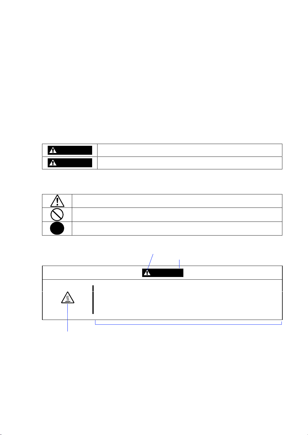
WARNING
CAUTION
Precautions and notices against hazards are presented with one of the following three symbols. The
individual symbols are defined as follows:
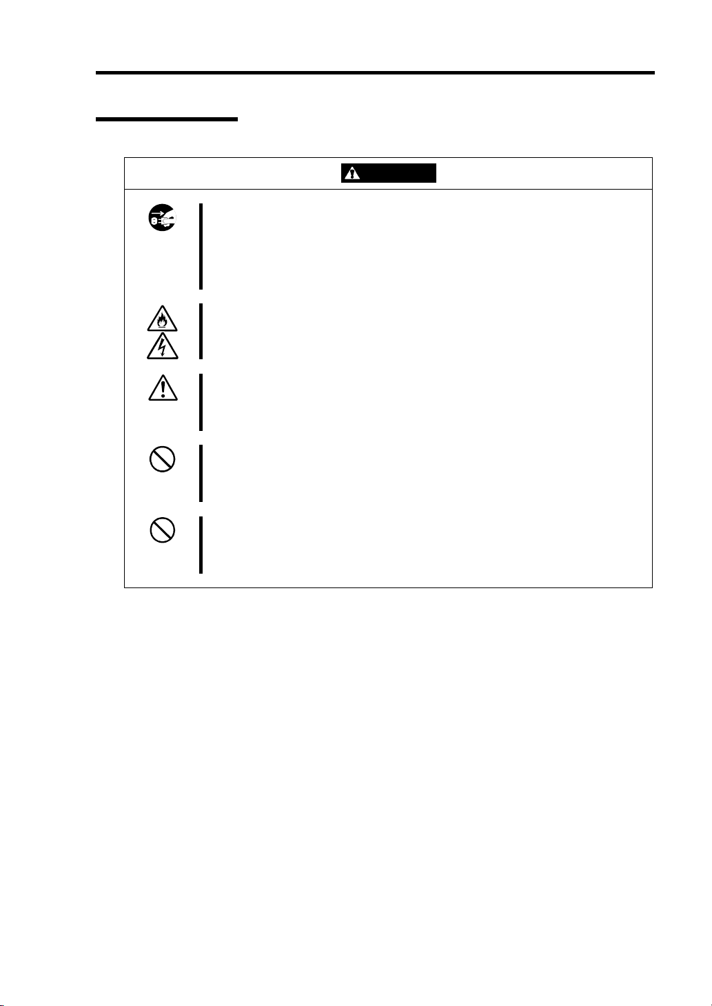
This symbol indicates the presence of a hazard.
An image in the symbol illustrates the hazard type. (Attention)
This symbol indicates prohibited actions. An image in the symbol illustrates a
particular prohibited action. (Prohibited Action)
This symbol indicates mandatory actions. An image in the symbol illustrates a
mandatory action to avoid a particular hazard. (Mandatory Action)
(Example)
Indicates the presence of a hazard that may result in death or serious
personal injury.
Indicates the presence of a hazard that may cause minor personal injury,
including burns, or property damage.
Symbol to draw attention
Term indicating a degree of danger
CAUTION
High temperature.
Immediately after the server is powered off, its internal components such as
hard disks are very hot. Leave the server until its internal components fully
cool down before installing/removing any component.
Symbol indicating a prohibited
action (may not always be
indicated)
Description of a danger
Page 4
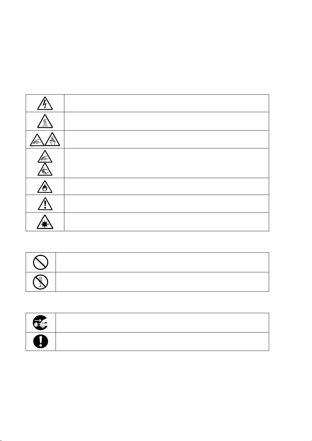
SYMBOLS USED IN THIS USER'S GUIDE AND WARNING LABELS
Attentions
Indicates that improper use may cause an electric shock.
Indicates that improper use may cause personal injury.
Indicates that improper use may cause fingers to be caught.
Indicates that improper use may cause the clip of a hand.
Indicates that improper use may cause fumes or fire.
Indicates a general notice or warning that cannot be specifically identified.
Indicates that improper use may cause loss of eyesight due to laser beam.
Prohibited Actions
Indicates a general prohibited action that cannot be specifically identified.
Do not disassemble, repair, or modify the server. Otherwise, an electric shock or fire
may be caused.
Mandatory Action
Unplug the power cord of the server. Otherwise, an electric shock or fire may be
caused.
Indicates a mandatory action that cannot be specifically identified. Make sure to
follow the instruction.
SAFETY INDICATIONS BY COLOR OF THE PARTS
Only green area is available for hot swap or hot plug operation. To avoid electric shock, disconnect
all AC cords before accessing to other parts especially blue area inside the system.
Page 5
NOTE: This equipment has been tested and found to comply with the limits for a Class A digital
device, pursuant to Part 15 of the FCC Rules. These limits are designed to provide reasonable
protection against harmful interference when the equipment is operated in a commercial
environment. This equipment generates, uses, and can radiate radio frequency energy and, if not
installed and used in accordance with the instruction manual, may cause harmful interference to
radio communications. Operation of this equipment in a residential area is likely to cause harmful
interference in which case the user will be required to correct the interference at his own expense.
CE Statement
Warning: This is a Class A product. In domestic environment this product may cause radio
interference in which case the user may be required to take adequate measures (EN55022).
BSMI Statement
CLASS 1
LASER PRODUCT
This system is classified as a CLASS 1 LASER PRODUCT. This
label is located on the internal CD-ROM installed in your system.
Page 6

Trademarks
NEC ESMPRO and NEC EXPRESSBUILDER are trademarks of NEC Corporation.
Microsoft, Windows, Windows 2000, and MS-DOS are registered trademarks or trademarks of Microsoft
Corporation in the United States and other countries.
Intel and Pentium are registered trademarks of Intel Corporation.
Xeon is a trademark of Intel Corporation.
Novell and NetWare are registered trademarks of Novell, Inc. of the United States.
Datalight is a registered trademark of Datalight, Inc.
ROM-DOS is a registered trademark of Datalight, Inc.
AT is a registered trademark of International Business Machines Corporation in the United States and other
countries.
Adaptec and its logo is a registered trademark of Adaptec, Inc. of United States.
SCSISelect is a trademark of Adaptec, Inc. of the United States.
Adobe, Adobe logo, and Acrobat are trademarks of Adobe Systems Incorporated.
DLT and DLTtape are trademarks of Quantum Corporation of the United States.
All other product, brand, or trade names used in this publication are the trademarks or registered trademarks of
their respective trademark owners.
Windows 2000 stands for Microsoft® Windows® 2000 Server operating system and Microsoft® Windows
2000 Advanced Server operating system, and Microsoft® Windows® 2000 Professional operating system.
Windows 2003 stands for Microsoft® Windows Server 2003 Server operating system and Microsoft
Windows Server 2003 Standard Edition and Enterprise Edition. Windows NT stands for Microsoft
Windows NT® Server network operating system version 3.51/4.0 and Microsoft® Windows NT® Workst a t i o n
operating system version 3.51/4.0. Windows Me stands for Microsoft® Windows® Millennium Edition
Operating System. Windows 98 stands for Microsoft® Windows®98 operating system. Windows 95 stands
for Microsoft® Windows®95 operating system.
®
®
®
Momentary voltage drop prevention:
This product may be affected by a momentary voltage drop caused by lightning. To prevent a
momentary voltage drop, an AC uninterruptible power supply (UPS) unit should be used.
Notes:
(1) No part of this manual may be reproduced in any form without the prior written permission of
NEC Corporation.
(2) The contents of this User's Guide may be revised without prior notice.
(3) The contents of this User’s Guide shall not be copied or altered without the prior written
permission of NEC Corporation.
(4) All efforts have been made to ensure the accuracy of all information in this User’s Guide. If
you notice any part unclear, incorrect, or omitted in this User’s Guide, contact the service
representative where you purchased this product.
(5) NEC assumes no liability arising from the use of this product, nor any liability for incidental or
consequential damages arising from the use of this User’s Guide regardless of Item (4).
Page 7

PREFACE
Welcome to the NEC Express5800/140Rc-4 server.
The NEC Express5800 server holds powerful performance and employs the latest technology to
implement a computer for the next generation. With its potential capabilities, the server may be
used as the workstation PC that configures a client-server system and provides high-speed
processing and superior reliability.
Read this User’s Guide thoroughly to fully understand handling of the server and appreciate its
functions to the maximum extent.
i
Page 8

ii
ABOUT THIS USER'S GUIDE
This User’s Guide is a guide for proper setup and use of the server.
This User’s Guide also covers useful procedures for dealing with difficulties and problems that may
arise during setup or operation of the server. Keep this manual for future use.
The following describes how to proceed with this User’s Guide.
How to Use This User's Guide
To aid you in finding information quickly, this User’s Guide contains the following information:
Chapter 1 Notes on Using Your Server
includes information that needs attention to use the server. Make sure to read this chapter
before setting up and using the server.
Chapter 2 General Description
includes information necessary to use the server, such as names and functions of its
components, handling of the floppy disk and CD-ROM drives. It also includes
requirements and advisory information for transfer and disposal of the server.
Chapter 3 Setting Up Your Server
tells you how to select a site, unpack the system, assemble the rack-mount subsystem,
make cable connections, and power on your system.
Chapter 4 Configuring Your Server
tells you how to configure the system and provides instructions for running the BIOS Setup
Utility and the Adaptec Configuration Utility, which is used to configure SCSI devices in your
system. This chapter also provides information on baseboard jumper settings.
Chapter 5 Installing the Operating System with Express Setup
describes how to install the operating system.
Chapter 6 Installing and Using Utilities
describes how to install the utilities for the server. It also includes a description on using
the attached CD-ROM "NEC EXPRESSBUILDER".
Chapter 7 Maintenance
provides you with all the information necessary to maintain successful operation of the
server. This chapter also includes a description on relocating and storing the server.
Chapter 8 Troubleshooting
contains helpful information for solving problems that might occur with your system.
Chapter 9 Upgrading Your Server
provides you with instructions for upgrading your system with an additional processor,
optional memory, optional add-in cards, hard disk drives, peripheral devices, and power
supply.
Appendix A Specification
provides specifications for your server.
Appendix B Other Precautions
provides supplementary notes on using the server.
Appendix C IRQ and I/O Port Address
provides a list of factory-set IRQs and I/O port addresses assigned.
Appendix D Installing Windows Server 2003
describes how to install Microsoft Windows Server 2003 without using Express Setup.
Using the Express Setup tool is recommended for installing Windows Server 2003. See
Chapter 5 for details.
Appendix E Installing Windows 2000
describes how to install Microsoft Windows 2000 without using Express Setup. Using the
Express Setup tool is recommended for installing Windows 2000. See Chapter 5 for details.
Appendix F Product Configuration Record Table
provides a table to be filled with your server configuration.
Page 9

Text Conventions
The following conventions are used throughout this User’s Guide. For safety symbols, see
"SAFETY INDICATIONS" provided earlier.
iii
IMPORTANT:
NOTE:
Items that are mandatory or require attention when using the server.
Notes give important information about the material being described.
IN THE PACKAGE
The carton contains various accessories, as well as the server itself. See the packing list to make
sure that you have everything and that individual components are not damaged. If you find any
component missing or damaged, contact your service representative.
Store the provided accessories in a designated place for your convenience. You will need
them to install an optional device or troubleshoot the server, as well as to set it up.
Make a backup copy of each provided floppy disk, if any. Store the original disk as the
master disk in a designated place, and use its copy.
Improper use of any provided floppy disk or CD-ROM may alter your system
environment. If you find anything unclear, immediately ask your service representative
for help.
Page 10

iv
(This page is intentionally left blank.)
Page 11

CONTENTS
Preface ..............................................................................................................................................i
About This User's Guide..................................................................................................................ii
In the Package.................................................................................................................................iii
Chapter 1 Notes on Using Your Server........................................................................ 1-1
Warning Labels.............................................................................................................................1-2
Safety Notes..................................................................................................................................1-3
General .....................................................................................................................................1-3
Notes on Installing and Accessing the Rack Cabinet ...............................................................1-5
Power Supply and Power Cord Use .........................................................................................1-6
Installation, Relocation, Storage, and Connection....................................................................1-7
Cleaning and Working with Internal Devices...........................................................................1-9
During Operation ...................................................................................................................1-11
For Proper Operation..................................................................................................................1-12
Transfer to Third Party ...............................................................................................................1-14
Consumables...............................................................................................................................1-15
Disposal of the Server.................................................................................................................1-15
User Support...............................................................................................................................1-16
v
Chapter 2 General Description ..................................................................................... 2-1
Overview ......................................................................................................................................2-2
Top View ..................................................................................................................................2-3
Front View................................................................................................................................2-4
Front View (with Front Bezel Removed) .................................................................................2-5
Front View (Switches and Lamps) ...........................................................................................2-6
Rear View.................................................................................................................................2-7
Internal View............................................................................................................................2-9
Electronics Bay ......................................................................................................................2-10
Baseboard...............................................................................................................................2-11
Processor Board .....................................................................................................................2-12
Memory Board .......................................................................................................................2-13
Standard Features .......................................................................................................................2-14
Power Supplies.......................................................................................................................2-15
Peripheral Bays ......................................................................................................................2-15
Memory Mirroring Feature ....................................................................................................2-16
Online Sparing Memory Feature............................................................................................2-16
SAF-TE Logic........................................................................................................................2-17
System Cooling ......................................................................................................................2-17
System Board Features...........................................................................................................2-18
Security ..................................................................................................................................2-22
NEC EXPRESSBUILDER ....................................................................................................2-23
NEC ESMPRO.......................................................................................................................2-24
Off-line Maintenance Utility..................................................................................................2-24
System Diagnostic Utility ......................................................................................................2-24
NEC Management Workstation Application (NEC MWA) ....................................................2-24
Page 12

vi
Using Your Server...................................................................................................................... 2-25
Front Bezel ............................................................................................................................ 2-25
POWER Switch..................................................................................................................... 2-26
POST ..................................................................................................................................... 2-27
SLEEP Switch ....................................................................................................................... 2-32
Floppy Disk Drive ................................................................................................................. 2-33
CD-ROM Drive..................................................................................................................... 2-35
Chapter 3 Setting Up Your Server ................................................................................3-1
Setup Flow ................................................................................................................................... 3-2
Selecting a Site............................................................................................................................. 3-3
Installation ............................................................................................................................... 3-3
Installation of Rack.................................................................................................................. 3-3
Unpacking the System ................................................................................................................. 3-5
Assembling the Rack-mount System ........................................................................................... 3-6
ESD Precaution ....................................................................................................................... 3-7
Checking Components.............................................................................................................3-7
Required Tools......................................................................................................................... 3-8
Installation Procedure.............................................................................................................. 3-9
Removal Procedure ...............................................................................................................3-22
Connecting Peripheral Devices.................................................................................................. 3-24
Connection to Serial Ports ..................................................................................................... 3-26
Connection to External SCSI Devices................................................................................... 3-32
Connecting Power Cord............................................................................................................. 3-33
Turning On the Server................................................................................................................ 3-35
Installing Operating System....................................................................................................... 3-37
Installing Utilities ...................................................................................................................... 3-37
Making Backup Copies of System Information......................................................................... 3-37
Chapter 4 Configuring Your Server.............................................................................. 4-1
System BIOS ~ SETUP ~ ............................................................................................................ 4-1
Starting SETUP Utility ............................................................................................................ 4-2
Description on On-Screen Items and Key Usage .................................................................... 4-3
Configuration Examples..........................................................................................................4-4
Menu and Parameter Descriptions........................................................................................... 4-9
SCSI BIOS ~ SCSISelect ~........................................................................................................ 4-35
Using SCSISelect Utility ....................................................................................................... 4-35
Configuring SCSI Controller on Baseboard .......................................................................... 4-36
Configuring SCSI Controller on Optional Board .................................................................. 4-44
Configuring Baseboard Jumpers................................................................................................ 4-45
Page 13

vii
Chapter 5 Installing the Operating System with Express Setup............................... 5-1
About Express Setup ....................................................................................................................5-2
Microsoft Windows Server 2003..................................................................................................5-4
Installation Notice ....................................................................................................................5-4
The Flow of Setup....................................................................................................................5-7
Installing the Windows Server 2003.........................................................................................5-8
Installing and Setting Device Drivers.....................................................................................5-12
Setting for Solving Problems .................................................................................................5-15
Installing Maintenance Utilities .............................................................................................5-18
Updating the System ..............................................................................................................5-19
Making Backup Copies of System Information .....................................................................5-19
Exceptional Setup...................................................................................................................5-20
Microsoft Windows 2000 ...........................................................................................................5-21
Installation Notice ..................................................................................................................5-21
The Flow of Setup..................................................................................................................5-25
Installing the Windows 2000..................................................................................................5-26
Installing and Setting Device Drivers.....................................................................................5-30
Setting for Solving Problems .................................................................................................5-34
Installing Maintenance Utilities .............................................................................................5-37
Updating the System - Applying Service Pack - ....................................................................5-38
Making Backup Copies of System Information .....................................................................5-38
Exceptional Setup...................................................................................................................5-39
Chapter 6 Installing and Using Utilities ....................................................................... 6-1
NEC EXPRESSBUILDER...........................................................................................................6-2
NEC EXPRESSBUILDER for DOS-Based with Local Console.............................................6-4
NEC EXPRESSBUILDER for DOS-based with Remote Console ........................................6-10
NEC EXPRESSBUILDER for Windows-Based (Master Control Menu)..............................6-13
Configuration Diskette Creator...................................................................................................6-14
NEC ESMPRO ...........................................................................................................................6-19
Functions and Features...........................................................................................................6-19
NEC MWA .................................................................................................................................6-20
Servers to be Remotely Managed by MWA ...........................................................................6-20
Precautions .............................................................................................................................6-20
Remote Management Configuration for the Server without Console ....................................6-21
Power Console Plus....................................................................................................................6-26
Major Functions .....................................................................................................................6-26
Components............................................................................................................................6-27
Server Setup ...........................................................................................................................6-29
Management PC Setup...........................................................................................................6-30
Page 14

viii
Chapter 7 Maintenance.................................................................................................. 7-1
Making Backup Copies................................................................................................................ 7-1
Cleaning....................................................................................................................................... 7-2
Cleaning the Server ................................................................................................................. 7-3
Cleaning the Interior................................................................................................................ 7-4
Cleaning the Keyboard/Mouse ................................................................................................ 7-5
Cleaning CD-ROM.................................................................................................................. 7-6
System Diagnostics...................................................................................................................... 7-7
Test Items................................................................................................................................. 7-7
Starting and Ending the System Diagnostics........................................................................... 7-8
Relocating/Storing the Server.....................................................................................................7-11
Chapter 8 Troubleshooting ........................................................................................... 8-1
System Viewers............................................................................................................................ 8-2
Lamps .......................................................................................................................................... 8-3
POWER/SLEEP Lamp............................................................................................................ 8-3
STATUS Lamp ........................................................................................................................ 8-4
DISK ACCESS Lamp.............................................................................................................. 8-6
LAN1/LAN2 ACCESS Lamp ................................................................................................. 8-6
UID Lamp................................................................................................................................ 8-7
Access Lamps.......................................................................................................................... 8-7
Hard Disk Drive Lamp (DISK Lamp)..................................................................................... 8-8
AC Standby Lamp ................................................................................................................... 8-9
Power Lamp .......................................................................................................................... 8-10
LAN Connector Lamps ..........................................................................................................8-11
PCI Slot Lamps...................................................................................................................... 8-12
FAN Fault Lamps .................................................................................................................. 8-13
Error Messages .......................................................................................................................... 8-14
Error Messages after Power-on ............................................................................................. 8-14
POST Error Messages ........................................................................................................... 8-15
Beep Codes............................................................................................................................ 8-21
Solving Problems....................................................................................................................... 8-22
Problems with Server ............................................................................................................8-22
Problems with NEC EXPRESSBUILDER............................................................................ 8-32
Problems with Express Setup ................................................................................................ 8-33
Error Message during Disk Array Configuration .................................................................. 8-36
Problems with Master Control Menu .................................................................................... 8-36
Problems with Configuration Diskette Creator ..................................................................... 8-37
Collecting Event Log ................................................................................................................. 8-38
Collect Configuration Information............................................................................................. 8-39
Collecting Dr. Watson Diagnostic Information.......................................................................... 8-40
Memory Dump........................................................................................................................... 8-40
Preparing for Memory Dumping ........................................................................................... 8-40
Saving the Dump File............................................................................................................8-41
Recovery for Windows 2000...................................................................................................... 8-42
Page 15

ix
Off-Line Maintenance Utility.....................................................................................................8-44
Starting the Off-line Maintenance Utility...............................................................................8-45
Features of Off-line Maintenance Utility ...............................................................................8-46
Resetting the Server....................................................................................................................8-47
Forced Shutdown........................................................................................................................8-47
Chapter 9 Upgrading Your Server ................................................................................ 9-1
Safety Notes..................................................................................................................................9-2
Anti-static Measures .....................................................................................................................9-3
Preparing for Installation and Removal........................................................................................9-4
Tools and Supplies Needed...........................................................................................................9-5
Device Installation or Removal Procedure ...................................................................................9-6
Hard Disk Drive .......................................................................................................................9-6
Power Supply Unit .................................................................................................................9-11
Server ~ Extending from the Rack Cabinet~..........................................................................9-15
Front Access Cover ................................................................................................................9-17
5.25-inch Peripheral Device...................................................................................................9-18
Rear Access Cover .................................................................................................................9-22
CPU Access Cover .................................................................................................................9-23
PCI Board...............................................................................................................................9-24
Memory Board .......................................................................................................................9-45
DIMM ....................................................................................................................................9-47
Processor Board Air Duct.......................................................................................................9-54
Processor Board .....................................................................................................................9-56
Processor (CPU).....................................................................................................................9-58
Cable Connection .......................................................................................................................9-63
IDE Interface..........................................................................................................................9-63
SCSI Interface ........................................................................................................................9-64
External SCSI Cable...............................................................................................................9-69
Serial Interface .......................................................................................................................9-71
Appendix A Specifications............................................................................................A-1
Appendix B Other Precautions.....................................................................................B-1
Transfer Rate of the On-board LAN Controller ...................................................................... B-1
Server Management Software ................................................................................................. B-1
Floppy Disk............................................................................................................................. B-1
CD-ROM................................................................................................................................. B-4
Tape Media.............................................................................................................................. B-4
Keyboard................................................................................................................................. B-5
Mouse...................................................................................................................................... B-6
Appendix C IRQ and I/O Port Address.........................................................................C-1
Page 16

x
Appendix D Installing Windows Server 2003 ............................................................. D-1
Before Installing Windows Server 2003 ......................................................................................D-1
Installing Service Pack ............................................................................................................D-1
Updating System .....................................................................................................................D-1
Disk Configuration (Concerning the area displayed as 'MAINTE_P') ....................................D-1
Re-installing to the Hard Disk which has been upgraded to Dynamic Disk............................D-1
MO Device ..............................................................................................................................D-2
Media such as DAT .................................................................................................................D-2
Partition Size ...........................................................................................................................D-2
Installing Windows Server 2003..................................................................................................D-3
Creating "Windows Server 2003 OEM-DISK for NEC EXPRESSBUILDER"......................D-3
Windows Server 2003 Clean Installation ................................................................................D-5
Updating the System................................................................................................................D-6
Upgrade installation.................................................................................................................D-7
Driver Installation and Advanced Settings...................................................................................D-9
PROSet ....................................................................................................................................D-9
Network Driver......................................................................................................................D-10
Re-install the Network Driver ...............................................................................................D-11
Installing SCSI Controller Driver..........................................................................................D-11
Setting for Collecting Memory Dump (Debug Information) ..................................................D-12
Appendix E Installing Windows 2000...........................................................................E-1
Before Installing Windows 2000..................................................................................................E-1
Installing Service Pack ............................................................................................................E-1
Updating System .....................................................................................................................E-1
Disk Configuration (Concerning the area displayed as 'MAINTE_P').................................... E-1
Re-installing to the Hard Disk which has been upgraded to Dynamic Disk............................E-2
MO Device .............................................................................................................................. E-2
Media such as DAT ................................................................................................................. E-2
Partition Size ...........................................................................................................................E-3
Installing Windows 2000 ............................................................................................................. E-4
Preparations for Installation..................................................................................................... E-4
Creating "Windows 2000 OEM-DISK for NEC EXPRESSBUILDER"................................. E-4
Windows 2000 Clean Installation............................................................................................ E-6
Driver Installation and Advanced Settings................................................................................... E-8
PROSet ....................................................................................................................................E-8
Network Driver........................................................................................................................E-9
Re-install the Network Driver ...............................................................................................E-10
Graphics Accelerator Driver.................................................................................................. E-11
Installing SCSI Controller Driver.......................................................................................... E-11
Setting for Collecting Memory Dump (Debug Information) .....................................................E-12
Appendix F Product Configuration Record Table.......................................................F-1
Hardware ................................................................................................................................. F-1
Software................................................................................................................................... F-3
Page 17

Chapter 1
Notes on Using Your Server
This chapter includes information necessary for proper and safe operation of your server.
Page 18
1-2 Notes on Using Your Server
A
r
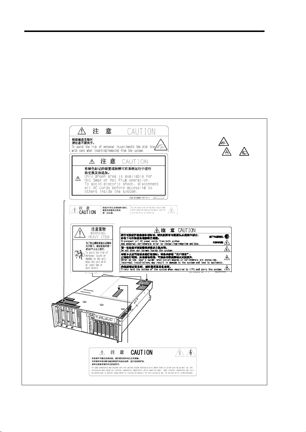
WARNING LABELS
The warning label is attached to components with possible danger or their vicinity in your server to
inform the user that a hazardous situation may arise when operating the server. (Do not
intentionally remove or damage any of the labels.)
If you find any labels totally/partially removed or illegible due to damage, contact your sales
representative.
The following Symbols have the
same meaning.
Old symbol:
New symbol:. or
?????????????
ttached to the CPU access cove
Page 19
Notes on Using Your Server 1-3
SAFETY NOTES
This section provides notes on using your server safely. Read this section carefully to ensure
proper and safe use of the server. For symbols, see "SAFETY INDICATIONS" provided earlier.
General
WARNING
Do not use the server for services where critical high availability may directly
affect human lives.
Your server is not intended to be used with or control facilities or devices
concerning human lives, including medical devices, nuclear facilities and
devices, aeronautics and space devices, transportation facilities and devices;
and facilities and devices requiring high reliability. NEC assumes no liability for
any accident resulting in personal injury, death, or property damage if the server
has been used in the above conditions.
Do not use the server if any smoke, odor, or noise is present.
If smoke, odor, or noise is present, immediately turn off the POWER switch and
disconnect the power plug from the outlet, then contact your service
representative. Using the server in such conditions may cause a fire.
Keep needles or metal objects away from the server.
Do not insert needles or metal objects into ventilation holes in the server or
openings in the floppy disk or CD-ROM drive. Doing so may cause an electric
shock.
Do not use the server in any unapproved place.
Install the server on a standard EIA 19-inch rack cabinet. Do not install the
rack containing the server in a place inappropriate to the rack installation
environment.
Failure to follow these instructions may cause some bad influences to be
imposed on your server and other systems installed on the rack and also a fire
or personal injury due to falling of the rack may occur. For the detailed
explanation on the place where your server should be installed and the
earthquake-resistant construction for the rack, refer to the manual attached to
the rack or contact your service representative.
Always install the server on a rack conforming to the relevant standard.
Install the server on a rack confirming to the EIA standard for the server to be
used. Do not use the server with installed on any other rack than standard EIA
19-inch rack or without the installation on a proper rack. Failure to follow these
instructions may cause your server to operate incorrectly and/or personal injury
or damages of surrounding devices to occur. Contact your service
representative for the racks available for your server.
Page 20
1-4 Notes on Using Your Server
Keep water or foreign matter away from the server.
Do not let any form of liquid (water etc.) or foreign matter (e.g., pins or paper
clips) enter the server. Failure to follow this warning may cause an electric
shock, a fire, or a failure of the server. When such things accidentally enter the
server, immediately turn off the power and disconnect the power plug from the
outlet. Do not disassemble the server. Contact your service representative.
CAUTION
Page 21
Notes on Using Your Server 1-5
Notes on Installing and Accessing the Rack Cabinet
CAUTION
Do not carry or install the rack cabinet only by a single person.
More than one person is required to carry or install the rack. Failure to follow this
instruction may cause the rack to fall to result in personal injury and/or breakages of
surrounding devices. In particular, a high rack (such as 44U rack) is unstable if it is
not fixed by stabilizers. More than one person must always carry or install the rack
while they support it.
Do not install the rack cabinet so that the load may be concentrated on a specific
point.
Install stabilizers on the rack so that the total load of the rack and devices mounted on
the rack is not concentrated on a singe point or join more than one rack with each
other to distribute the load. Failure to follow this instruction may cause the rack to
fall to result in personal injury.
Do not install components on the rack cabinet only by a single person.
More than one person is required to install parts including the doors and trays for the
rack. Failure to follow this instruction may cause some parts to fall to be broken
and/or to result in personal injury.
Do not pull out a device from the rack if the rack is unstable.
Always pull out a device from the rack in the state that the rack is made stable (by the
installation of stabilizers or earthquake-resistant construction).
Do not leave more than one device being pulled out from the rack.
Pulling out more than one device from the rack may cause the rack to be fallen.
Only pull out a single device from the rack at a time.
Do not provide the wiring for the rack cabinet to exceed the rating of the power
supply.
To prevent burns, fires, and device damages, the power supplied to the power supply
in the rack shall not exceed the rating load of the power branch circuit. Contact your
electric constructor or the local power company for the requirements on the wiring
and installation of electric facilities.
Page 22
1-6 Notes on Using Your Server
Power Supply and Power Cord Use
Do not hold the power plug with a wet hand.
Do not disconnect/connect the plug while your hands are wet. Failure to follow
this warning may cause an electric shock.
Plug in to a proper power source.
Use a proper wall outlet. Use of an improper power source may cause a fire or
a power leak.
Do not install the server where you need an extension cord. Use of a cord that
does not meet the power specifications of your server may heat up the cord and
cause a fire.
Do not connect the power cord to an outlet that has an illegal number of
connections.
The electric current exceeding the rated flow overheats the outlet, which may
cause a fire.
Insert the power plug into the outlet as far as it goes.
Heat generation resulting from a halfway inserted power plug (imperfect contact)
may cause a fire. Heat will also be generated if condensation is formed on dusty
blades of the halfway inserted plug, increasing the possibility of fire.
Use the authorized power cord only.
Use only the power cord that comes with your server. Use of an unauthorized
power cord may cause a fire when the electric current exceeds the rated flow.
Also, observe the following to prevent an electric shock or fire caused by a
damaged cord.
■ Do not stretch the cord harness.
■ Do not pinch the power cord.
■ Do not bend the power cord.
■ Keep chemicals away from the power cord.
■ Do not twist the power cord.
■ Do not place any object on the power cord.
■ Do not bundle power cords.
■ Do not alter, modify, or repair the power cord.
■ Do not secure the power cord with staples or equivalents.
■ Do not use any damaged power cord. (Replace a damaged power cord with
a new one of the same specifications. Ask your service representative for
replacement.)
Do not use the attached power cord for any other devices or usage.
The power cord that comes with your server is designed aiming to connect with
this server and to use with the server, and its safety has been tested. Do not use
the attached power cord for any other purpose. Doing so may cause a fire or an
electric shock.
WARNING
CAUTION
Page 23
Notes on Using Your Server 1-7
Installation, Relocation, Storage, and Connection
CAUTION
Never attempt to lift the server only by yourself.
Your server weighs 33 kg (depending on its hardware configuration). Carrying
the server only by yourself may strain your back. Hold the server firmly by its
bottom with another person to carry it. Do not hold the front bezel to lift the
server. The front door may be disengaged from the server, causing personal
injury.
Do not install your server on a rack with leaving covers removed.
Do not install your server on a rack with the cover being removed. Failure to
follow this instruction may reduce the cooling effect in the server to result in
some malfunction and/or dusts to enter the server to result in a fire or electric
shock.
Do not pinch your finger with rails or other components.
Note sufficiently that your fingers may not be caught between a rail and another
mechanical part or cut by a rail at installation or removal of the server from the
rack. When unlocking the latched server in the rack cabinet, use a screwdriver
or tools to press the release levers on the slide rail. Pressing the levers with your
finger may cause an injury.
Do not apply any load on the server pulled out from the rack.
Do not apply any load on the server pulled out from the rack. Doing so bends
the frame of the server. Consequently, the server cannot be pushed back into
the rack. Placing an object on the server may also cause personal injury if the
server drops.
Do not install the server in any place other than specified.
Do not install the server in the following places or any place other than specified
in this manual. Failure to follow this instruction may cause a fire.
■ a dusty place
■ a humid place such as near a boiler
■ a place exposed to direct sunlight
■ an unstable place
Do not use the equipment in the place where corrosive gases exist.
Make sure not to locate or use the server in the place where corrosive gases
(sulfur dioxide, hydrogen sulfide, nitrogen dioxide, chlorine, ammonia, ozone,
etc) exist.
Also, do not set it in the environment where the air (or dust) includes
components accelerating corrosion (ex. sulfur, sodium chloride) or conductive
metals. There is a risk of a fire due to corrosion and shorts of an internal printed
board.
Page 24
1-8 Notes on Using Your Server
Do not connect any interface cable with the power cord of the server plugged to
a power source.
Make sure to power off the server and unplug the power cord from a power
outlet before installing/removing any optional internal device or
connecting/disconnecting any interface cable to/from the server. If the server
is off-powered but its power cord is plugged to a power source, touching an
internal device, cable, or connector may cause an electric shock or a fire
resulted from a short circuit.
Do not use any unauthorized interface cable.
Use only interface cables provided by NEC and locate a proper device and
connector before connecting a cable. Using an authorized cable or connecting
a cable to an improper destination may cause a short circuit, resulting in a fire.
Also, observe the following notes on using and connecting an interface cable.
■ Do not use any damaged cable connector.
■ Do not step on the cable.
■ Do not place any object on the cable.
■ Do not use the server with loose cable connections.
CAUTION
Page 25
Cleaning and Working with Internal Devices
WARNING
Do not disassemble, repair, or alter the server.
Never attempt to disassemble, repair, or alter the server on any occasion other
than described in this manual. Failure to follow this instruction may cause an
electric shock or fire as well as malfunctions of the server.
Do not look into the CD-ROM drive.
A laser beam used in the CD-ROM drive is harmful to the eyes. Do not look
into or insert a mirror into the drive while the drive is powered. If a laser beam
is caught in your eyes, you may lose your eyesight (the laser beam is invisible).
Do not remove the lithium battery.
Your server contains the lithium battery. Do not remove the battery. Danger of
explosion if the battery is incorrectly replaced. Placing the lithium close to a fire
or in the water may cause an explosion.
When the server does not operate appropriately due to the dead lithium battery,
contact your service representative to replace only with the same or equivalent
type recommended by NEC. Do not disassemble the server to replace or
recharge the battery by yourself.
Disconnect all the power plugs before accessing inside the server, or connecting
the peripherals.
Notes on Using Your Server 1-9
The server has two power cords.
Make sure to power off the server and disconnect the all power plugs from a
power outlet before cleaning or installing/removing internal optional devices.
Touching any internal device of the server with its power cords connected to a
power source may cause an electric shock even of the server is off-powered.
Disconnect all the power plugs from the outlet occasionally and clean the plug
with a dry cloth. Heat will be generated if condensation is formed on a dusty
plug, which may cause a fire.
Page 26
1-10 Notes on Using Your Server
Hot surface
Immediately after the server is powered off, its internal components such as
hard disks are very hot. Leave the server until its internal components fully
cool down before installing/removing any component.
Make sure to complete board installation.
Always install a board firmly. An incompletely installed board may cause a
contact failure, resulting in smoking or fire.
Protect the unused connectors with the protective cap.
The unused power supply cable connectors are covered with the protective cap
to prevent short circuits and electrical hazards. When removing the power
supply cable connector from the internal devices, attach the protective cap to the
connector. Failure to follow this warning may cause a fire or an electric shock.
Do not touch any electrical components inside the server during the hot-swap
replacement.
All power flows inside the server while the hot-swap replaceable components
(PCI add-in cards, hard disk, cooling fan, and power supply). Do not touch the
electrical components inside the server to avoid an electric shock.
CAUTION
Page 27
During Operation
Avoid contact with the server during thunderstorms.
Disconnect all the power plugs from the outlet when a thunderstorm is
approaching. If it starts thundering before you disconnect the all power plugs,
do not touch any part of the server including the cables. Failure to follow this
warning may cause a fire or an electric shock.
Keep animals away from the server.
Failure to follow this warning may cause a fire or an electric shock.
Do not place any object on top of the server.
An object placed on top of the server may fall down, resulting in damage to your
property around the server.
Do not use a cellular phone or pager around the server.
Notes on Using Your Server 1-11
CAUTION
Turn off the cellular phone or pager. Radio interference may cause
malfunctions of the server.
Do not remove the cooling fans.
Only an authorized NEC service technician can remove the cooling fans from
the server.
Page 28

1-12 Notes on Using Your Server
FOR PROPER OPERATION
Observe the following notes for successful operation of the server. Use of the server ignoring the
notes will cause malfunctions or failures of the server.
Install the server in a place that meets requirements for successful operation. For details,
see Chapter 3, "Setting Up Your Server."
Do not delete the hard disk partition exclusively provided for maintenance of the server
although it may appear on the OS.
Make sure to power off the server before connecting or disconnecting cables between the
server and peripheral devices.
Verify that the access lamp on the server is unlit before turning off the server or ejecting
the floppy disk.
The server management logic on your system board monitors and logs system voltage
changes. When plugging the power cord to the system, you may experience 10 seconds
delay from the time you press the POWER switch on the front panel. This is normal
system operation and is required by the server management logic.
When you have just turned off the server, wait at least 30 seconds before turning it back
on.
Do not turn off the server until characters following the "NEC" logo appears on the
screen.
Turn off the power and unplug the power cord from the outlet before relocating the server.
Some software includes a command to eject the CD-ROM tray. Make sure that the front
bezel is removed before running the command. Running this command with the front
bezel installed may cause the CD-ROM tray or the media to hit against the front bezel,
resulting in a failure of the server
Clean the server on a regular basis. (See Chapter 7 for cleaning.) Regular cleaning
proactively prevents various failures of the server.
Lightning may cause a momentary voltage drop. To prevent this problem, it is
recommended to use of an uninterruptible power supply unit.
Check and adjust the system clock before the operation if any of the following conditions
is applicable.
– After carriage of the server
– After storage of the server
– After the server is entered into the pause state under the environmental condition
enduring the server operation (temperature: 10°C - 35°C, humidity: 20% - 80%)
Check the system clock at the rough rate of once per month. When the system clock is
installed in a system requiring high time precision, it is recommended to use a time server
(NTP server).
If the system clock is remarkably delayed or advanced as the passage of time in spite of
adjustment, contact your sales agent to ask maintenance.
Page 29

Notes on Using Your Server 1-13
Store the unit under the storage condition (temperature: -10°C - 55°C, humidity: 20% -
80%, without condensation) to allow built-in devices and the unit to operate correctly in
the next operation.
Make sure to use optional devices supported by the server. Some non-supported devices
may be physically installed/connected but cause failures of the server as well as a
malfunctions of the server.
NEC recommends you use NEC's genuine products. Some third-party products claim
that they support the server. However, repair of the server due to a failure or damage
resulted from use of such third-party products will be charged.
For the disk which does not conform to the CD standard, the playback of such a disk with
the CD drive is not guaranteed.
Page 30

1-14 Notes on Using Your Server
TRANSFER TO THIRD PARTY
The following must be observed when you transfer (or sell) the server or software provided with the
server to a third party:
NEC Express server
Make sure to provide this manual along with the server to a third party.
IMPORTANT: About data on the hard disk
Be sure to take appropriate measures not to leak important data (e.g.,
customers' information or companies' management information) on the
removed hard disk to any third parties.
Data seems to be erased when you empty "Recycle Bin" of Windows or
execute the "format" command of the operating system. However, the
actual data remains written on the hard disk. Data not erased completely
may be restored by special software and used for unexpected purposes.
It is strongly recommended that the software or service (both available
at stores) for data erasure should be used in order to avoid the trouble
explained above. For details on data erasure, ask your sales
representative.
Provided software
To transfer or sell any software application that comes with the server to a third party, the following
requirements must be satisfied:
All provided software applications must be transferred and no backup copies must be
retained.
Transfer requirements listed in "Software License Agreement" that comes with each
software application must be satisfied.
Software applications that are not approved for transfer must be uninstalled before
transferring the server.
Page 31
Notes on Using Your Server 1-15
CONSUMABLES
Your server contains some components that are only good for a limited period of time and require
replacement, such as fans, the internal CD-ROM drive, the floppy disk drive, and the mouse. For
stable operation of the server, NEC recommends you replace these components on a regular basis.
Consult with your service representative for replacement or the product lives.
DISPOSAL OF THE SERVER
Dispose the server, all the internal devices, floppy disks, and CD-ROMs according to all national
laws and regulations.
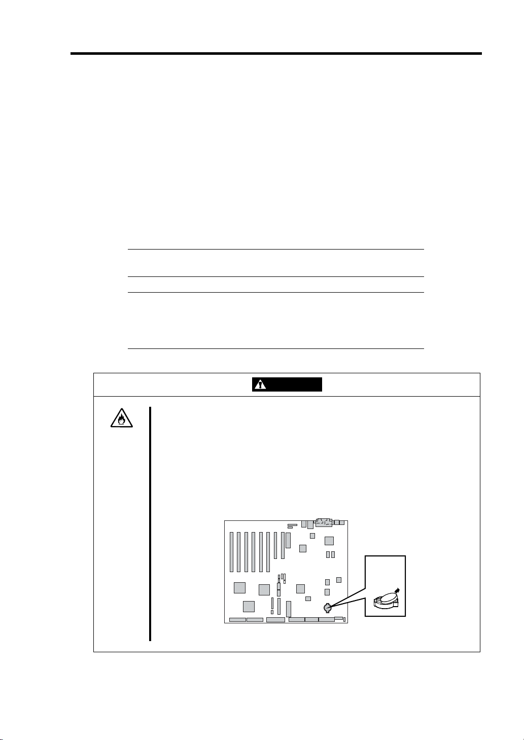
IMPORTANT: For disposal (or replacement) of the battery on the
baseboard of the server, consult with your service representative.
NOTE: If the real-time clock battery on the baseboard leaches its life,
the following message appeared on the display while running the POST.
Contact your service representative to replace the battery.
250 System battery is dead –Replace and run SETUP
WARNING
Do not remove the lithium battery.
Your server contains the lithium battery. Do not remove the battery. Danger of
explosion if the battery is incorrectly replaced. Placing the lithium or nickel
cadmium battery close to a fire or in the water may cause an explosion.
When the server does not operate appropriately due to the failure of lithium
battery, contact your service representative to replace only with the same or
equivalent type recommended by NEC. Do not disassemble the server to
replace or recharge the battery by yourself.
Baseboard
Page 32

1-16 Notes on Using Your Server
USER SUPPORT
When the server needs after-sales service, check if the warranty is still valid, and determine which
service is necessary as indicated on the "Certificate".
Before Asking for Repair, do the following when the server appears to fail:
1. Check if the power cord and the cables to other devices are properly connected.
2. See Chapter 8 to find if your problem fits the description. If it does, take the
recommended measure for it.
3. Check if the software required for operation of the server is properly installed.
4. Check the server using a computer virus detection program. Computer virus detection
programs are available for purchase in stores.
If the server still appears to fail after you have taken the above actions, consult with your service
representative immediately. Take notes on lamp indications of the server and alarm indications on
the display unit before consultation, which may provide a significant help to your service
representative.
When Having Your Server Repaired
Prepare the following when having your server repaired:
Certificate
Notes of the messages displayed on the display unit
Error information*
Records of the NEC Express server and peripheral equipment
* Error information includes the Error Message shown in Chapter 8.
Prepare the error information only when required by your service representative.
Page 33

Notes on Using Your Server 1-17
Advice for Health
The longer you keep using the computer equipment, the more you become
tired, which may cause disorders of your body. When you use a
computer, observe the following to keep yourself from getting tired:
Good Working Posture
You have good posture if the following are satisfied when you use a
computer:
• You sit on a chair with your back straight.
• Your hands are parallel with the floor when you put them on the
keyboard.
• You look at the screen slightly lower than your eye height.
You have "good working posture" as described in the above when no part
of your body is under excess strain, in other words when your muscles are
most relaxed.
You have "bad posture" when you sit with your back hunched up or you
operate a display unit with your face close to the screen. Bad working
posture may cause eye strain or poor eyesight.
Adjustment of Display Unit Angles
Most display units are designed for adjustment of the horizontal and
vertical angles. This adjustment is important to prevent the screen from
reflecting bright lights and to make the display contents easy to see. You
will not be able to keep "good working posture" and you will feel more tired
than you should if you operate a display unit without adjusting horizontal
and vertical angles.
Adjustment of Screen Brightness and Contrast
The display unit has brightness and contrast adjustment functions. The
most suitable brightness and contrast depend on the individual and the
working environment (well-lighted room or insufficient light). Adjust
brightness and contrast so that the screen will be easy to see. An
extremely bright or dark screen will give a bad effect to your eyes.
Adjustment of Keyboard Angle
The keyboard provided with the server is designed for adjustment of an
angle. Adjust the keyboard angle at which the keyboard is easy to
operate. The adjustment assists in reducing strain on your shoulders,
arms, and fingers.
Cleaning of Equipment
Clean equipment regularly. It is difficult to see the display contents on a
dusty screen. Keeping equipment clean is also important for your sight.
Fatigue and Rest
If you feel tired, you should stop working and do light exercises.
Page 34

1-18 Notes on Using Your Server
(This page is intentionally left blank.)
Page 35

Chapter 2
General Description
This chapter provides information that you should be familiar with before using the server. It
includes names and functions of the components and features of the server.
Page 36

2-2 General Description
OVERVIEW
Your server is a highly reliable, high-powered, fault-tolerant, high-capacity, multiprocessing server
based on the Intel Xeon Processor MP. It is a solid performer and offers the latest technology.
The combination of compute performance, memory capacity, and integrated I/O provides a high
performance environment for many server market applications. These range from large
corporations supporting remote offices to small companies looking to obtain basic connectivity
capability such as file and print services, e-mail, web access, web site server, etc.
Your server is housed and available as a rack-mount system. Your server conveniently installs into
a standard EIA 19-inch rack cabinet.
Your server includes a 3.5-inch diskette drive, a CD-ROM drive, a 3.5-inch hard disk bay, and
removable media device bay. The 3.5-inch hard disk bay supports up to five 1.0-inch SCSI hard
disk drives that can be swapped in or out of the system without powering it down, if RAID
functionality is configured in the system.
As application requirements increase, you can expand your server with an additional processor,
additional memory, add-in boards and peripheral devices: tape devices, CD-ROM, and hard disk
drives.
Page 37

Top View
General Description 2-3
2
1
1 Front access cover
Open the front access cover
• to replace any defected fan with a normal one. The fans are hot-swappable.
Do not remove any fans which are not defected.
If a fan is defected, do not replace it by yourself but contact your service representative to
request the replacement.
• to install or remove optional 5.25-inch device and change some internal cable connections.
2 Rear access cover
Open the rear access cover to install or remove optional PCI boards, optional processors and
DIMMs.
Page 38

2-4 General Description
Front View
See "Lamps" described later.
21
1
2
1 Front bezel
Remove the front bezel when you access to the POWER/SLEEP switch, the CD-ROM drive,
or the floppy disk drive or install or remove a hard disk drive from the 3.5-inch hard disk bay.
The front bezel can be locked by using the attached security key.
2 Key hole
Insert the security key to lock/unlock the front bezel
Page 39
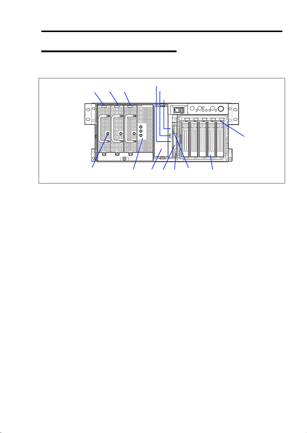
Front View (with Front Bezel Removed)
See Chapter 8 for detail information on lamp indication.
General Description 2-5
1-121-2 1-3
3 4 7
1 Power supply unit
The power supply unit supplies DC powers to the server. The slot 1-3 is for optional slot.
2 Power lamp
When the power of the server is turned on, the lamp goes on green.
3 AC Standby lamp
If the power cord is connected to the AC inlet to supply AC power to the power supply unit, the
lamp goes on green except for the lamp indicated AC_R. If the power system of the server is in
the redundant function, after turning on the server, the lamp indicated AC_R goes on green.
4 5.25-inch device bay
Backup tape drives may be installed in the 5.25-inch device bay.
5 CD-ROM drive
The CD-ROM drive reads data from the inserted CD-ROM.
5-1: Access lamp (lit orange during accessing)
5-2: CD tray eject button
5-3: Emergency hole
6 3.5-inch floppy disk drive
Insert a 3.5-inch floppy disk to the 3.5-inch floppy disk drive to read data from the disk or write
data to the disk.
6-1: Eject button
6-2: Disk inserting section
6-3: Floppy disk access lamp (lit green during accessing)
7 3.5-inch hard disk bay
The 3.5-inch hard disk bay contains additional hard disk slots. Hard disks having the
thickness of 1 inch can be inserted into the slots.
The SCSI IDs are defined as follows:
ID0 to ID4 from right to left
8 Disk lamp (green/amber)
The disk lamp is lit green if a hard disk installed in the server is accessed. If a hard disk is
defected, the lamp is lit amber. During the rebuild processing, the lamp is lit green or amber
alternately. (This occurs only in the disk array configuration.)
5-1
5-2
5-3
8
6-1 6-2 6-3
Page 40

2-6 General Description
Front View (Switches and Lamps)
See Chapter 8 for detail information on lamp indication.
1 2 3 4 5 6 7 8
9 10 11 11 12
1 Serial port B connector
The serial port B connector is used to connect the server to a device with the serial interface.
The server cannot be directly connected to a leased line through the connector.
IMPORTANT: Only the RJ-45 serial interface cable can be connected to this port. Do not
connect any other interface cables such as the Ethernet cable. Doing so could damage the
device, your server, or both.
2 USB3 connector
The USB3 connector allows the server to be connected to a device accepting the USB
interface.
3 SLEEP switch
Pressing the sleep switch once causes the server to enter into the sleep state (power saving
mode). Pressing the power switch in the sleep state recovers the machine to the normal
state. (This function is supported by Windows 2000.)
4 UID (Unit ID) switch
Pressing the UID switch turns UID lamp (blue) located on the front panel and the rear panel on
and off. The UID lamp located on the rear panel is visible through the rear of the chassis and
allows you to locate the server you're working on from the rear of the servers on a rack.
5 UID lamp (blue)
Lights in blue when the ID switch is pressed.
6 RESET switch
The reset switch is used to reset the server.
7 POWER/SLEEP lamp (green)
Lights in green when the server is powered on. Goes off when the server is powered off.
Blinks when the system is placed in the sleep mode.
8 POWER switch
The power switch is used to turn on/off the power. If you press the switch once, then the
POWER/SLEEP lamp goes on and the power is turned on. If you press the switch again, the
power is turned off. The system is forcibly shut down when the power switch is pressed
continuously for four seconds or longer.
9 Dump switch
The dump switch is used to collect the event logs having occurred in the server.
10 STATUS lamp (green/amber)
Lights in green while the server is in successful operation. When any error is detected, this
lamp lights or blinks in amber.
11 LAN1/LAN2 ACCESS lamp (green)
Lights in green while the server is connected to the network. Blinking in green indicates the
network activity. Numbers printed near the lamps indicate the LAN port number.
12 DISK ACCESS lamp (green/amber)
Lights in green while the internal hard disk is in access. When any one of the internal hard
disks fails, this lamp lights in amber.
Page 41

Rear View
See Chapter 8 for detail information on lamp indication.
1 2 3-1 3-2 4 5 6
7
8
20
General Description 2-7
13-1
9 10 11 12
1 AC inlet 1
The AC inlet 1 is connected with the power cord coming with the server.
2 AC inlet 2
The AC inlet 2 is used when the additional power supply unit is installed in the server.
3 ICMB-1 (left) ICMB-2 (right) connector
The ICMB connector is connected to a device having the ICMB interface.
4 Serial port B connector
The serial port B connector is used to connect the server to a device with the serial interface.
The server cannot be directly connected to a leased line through the connector.
For using this port, the rear serial cable that comes with your server should be connected to
this connector.
5 External SCSI connector
The external SCSI connector is used to connect the server to external SCSI devices. For the
connection, attached SCSI cable is necessary and some cable connections must be changed
on the baseboard.
6 PCI slot power lamp (green) (upper)
The PCI slot power lamp is lit when the power of the PCI slot being on.
6 PCI slot fault lamp (amber) (lower)
PCI slot fault lamp blinks when the hot plug PCI function is enabled with Windows 2000. The
lamp also goes on if a fault occurs in the PCI board installed into the slot or the slot itself.
7 Printer port connector
The printer port connector is connected with a printer with the Centronics interface.
13-2
17 18 17 19 21
14 15
16
Page 42

2-8 General Description
8 UID lamp (blue)
This lamp is lit when the UID switch is pressed.
9 Keyboard connector
The keyboard connector is connected with PS/2 type keyboard.
10 Mouse connector
The mouse connector is connected with the PS/2 type mouse.
11 Serial port A connector
The serial port A connector is connected with a device having the serial interface.
The server can't directly be connected to a leased line through the connector.
12 Monitor connector
The monitor connector is connected with the display unit.
13 USB-1 - USB-2 connectors
The USB-1 (upper) and USB-2 (lower) connectors are connected with devices accepting the
USB interface.
14 Additional PCI board slots
Optional PCI boards (32-bit/33MHz) may be inserted into the slots.
15 Additional PCI board slots
Optional PCI boards (64-bit/100 MHz) may be inserted into the slots.
16 Additional PCI hot-plug board slots
Optional PCI hot-plug boards (64-bit/100 MHz) may be inserted into the slots.
17 LINK/ACT lamp
The LINK/ACT lamp shows the LAN access status.
18 LAN1 connector
The LAN1 connector is connected with a network system on LAN. This port can be operated
through 100BASE-TX or 10BASE-T interface.
19 LAN2 connector
The LAN2 connector is connected with a network system on LAN. This port can be operated
through 1000BASE-T, 100BASE-TX or 10BASE-T interface.
20 100/10 lamp
The 100/10 lamp indicates the LAN transfer rate.
21 1000/100/10 lamp
The 1000/100/10 lamp indicates the LAN transfer rate.
Page 43

Internal View
General Description 2-9
3
2
1
1 Fan bay (6 Cooling fans are located in this bay.)
2 Electronics bay
3 Additional PCI board slots (8 slots)
4 Hot Plug PCI LED Board
5 Memory board
6 Processor board air duct
7 Cover open sensor
4
5
6
7
Page 44

2-10 General Description
Electronics Bay
1
2
3
4
5
1 Hot-plug PCI board slots
2 Non-hot-plug PCI board slots
3 Dummy sponge
4 Processor board
5 Baseboard
Page 45
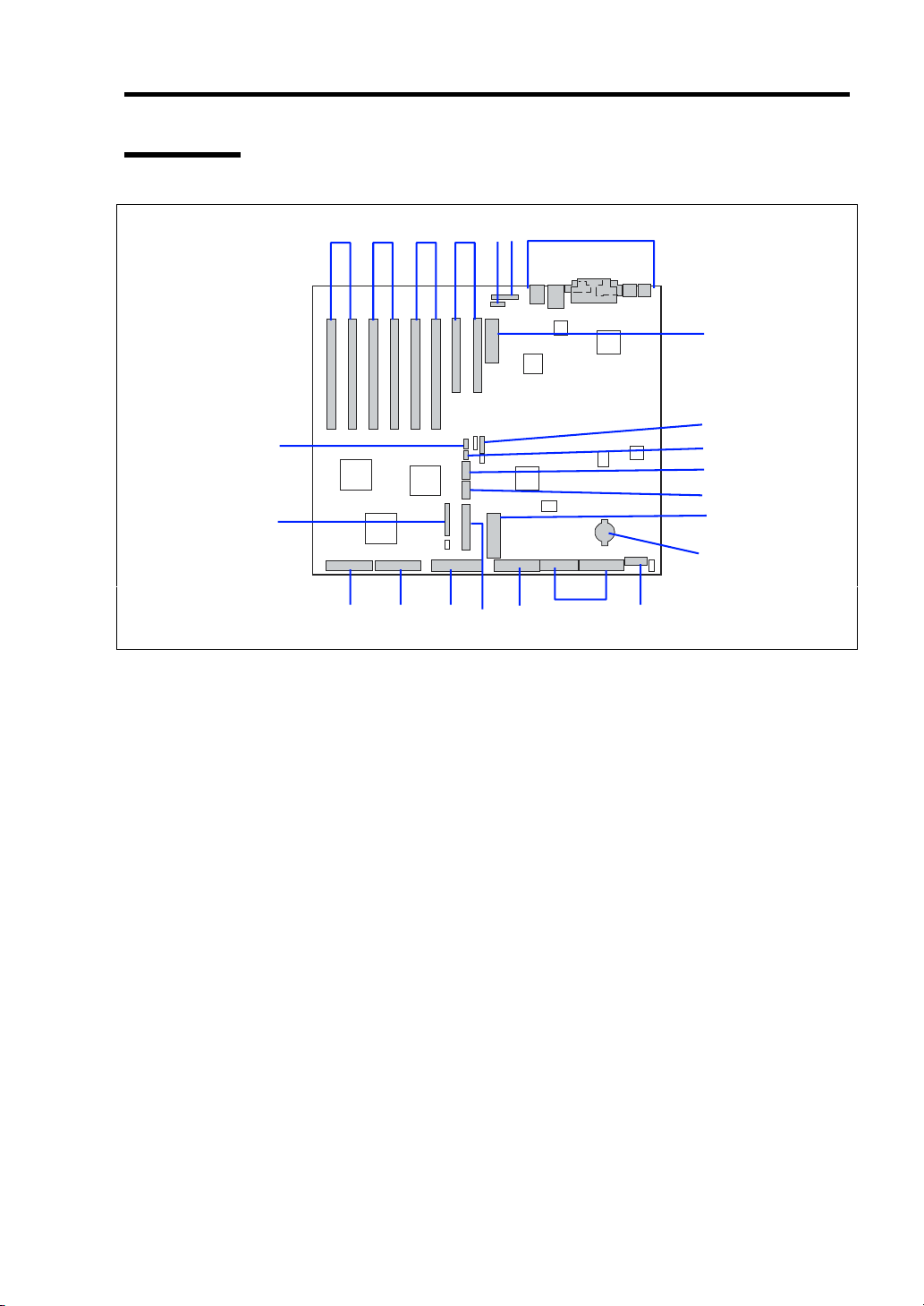
Baseboard
19
18
General Description 2-11
1-4 1-3 1-2 1-1 2 3 4
5
6
7
8
9
5
10
14
1 Additional PCI board slots (8slots)
1-1: PCI#1 and 2 (1st PCI Bus, 32-bit, 33MHz, 5V PCI (arranged from right to left))
1-2: PCI#3 and 4 (3rd PCI Bus, 64-bit, 100MHz, 3.3V PCI–X (arranged from right to left))
1-3: PCI#5 and 6 (4th PCI Bus, 64-bit, 100MHz, 3.3V PCI–X Hot plug)
(arranged from right to left)
1-4: PCI#7 and 8 (5th PCI Bus, 64-bit, 100MHz, 3.3V PCI–X Hot plug)
(arranged from right to left)
2 Intelligent Chassis Management Bus (ICMB) connector
3 Hot Plug PCI LED Board connector
4 Rear panel I/O connectors (see page 2-7)
5 Processor board interface connectors
6 Jumper switch for clearing CMOS/password
7 Hot-swap back plane (HSBP Primary) connector
8 COM B connector
9 USB #3 connector
10 Lithium battery
11 Power connector
12 Power connector
13 Floppy disk drive connector
14 Front panel board interface connector
15 IDE connector (for CD-ROM drive)
16 Ultra320(B) connector (for 5.25-inch or external SCSI device)
17 Ultra320(A) connector (for 3.5-inch hard disk bay)
18 Cooling fan connector
19 Hot-swap back plane (HSBP Secondary) connector
111213151617
Page 46

2-12 General Description
Processor Board
2
5 1 6 5
3 4
1 CPU1 socket (the default processor is installed in this socket)
2 CPU2 socket (the optional processor should be installed in this socket)
3 CPU3 socket (the optional processor should be installed in this socket)
4 CPU4 socket (the optional processor should be installed in this socket)
5 Baseboard interface connectors
6 Memory board interface connector
Page 47

Memory Board
1
1 DIMM socket
The default DIMMs are installed in the sockets 1 to 4.
The optional DIMMs should be installed in the sockets 5 to 12.
To enable the online sparing / memory mirroring feature, see Chapter 9 "DIMM".
2 Processor board interface connector
General Description 2-13
2
Page 48

2-14 General Description
STANDARD FEATURES
High performance Expandability
Intel
High-speed memory access
High-speed 1000BASE-T/100BASE-
High-speed disk access
High-reliability Self-diagnosis
Memory mirroring feature
Online sparing memory feature
Memory monitoring feature (single-bit
CPU/memory degradation feature
Bus parity error detection
Thermal sensor
Error notification
Internal cooling fan monitoring feature
Internal voltage monitoring feature
BIOS password feature
Security feature (security lock)
Redundant power supply
Disk array (optional)
Management Utilities
NEC ESMPRO
NEC Management Workstation
XeonTM Processor MP
N8100-1023F: 2.20GHz/2MB
N8100-1024F: 3GHz/4MB
(Supports PC-200-compliant registered
ECC DDR DRAM)
TX/10BASE-T interface
(1000Mbps/100Mbps/10Mbps supported)
(Ultra320 SCSI x 2)
error correction/ double-bit error
detection)
(logical isolation of a failed device)
Application (NEC MWA)
Wide variety of optional I/O slots
Two 32-bit/33 MHz PCI slots
Six 64-bit/100 MHz PCI-X sots
(four slots support hot-plug)
Large memory of up to 24 GB
3.5-inch hard disk drive bay holds five
hot-swap SCSI hard disk drives
Remote power-on feature
Up to four multi-processors are available
for upgrade.
Many SCSI device connection patterns
USB interface
Many Available Features
Graphic accelerator "RAGE XL" support
El Torito Bootable CD-ROM (no
emulation mode) format support
POWER switch mask
Software power-off
Remote power-on feature
AC-LINK feature
Intelligent Platform Management
Interface (IPMI) feature
Baseboard Management Controller
(BMC)
Remote console feature
Power On Self-Test (POST)
Test and Diagnosis (T&D)
Maintenance Features
Off-line Maintenance Utility
Memory dump feature using the DUMP
switch
Power Saving Feature
Sleep feature (available for Windows
Server 2003/Windows 2000)
Easy and Fine Setup
NEC EXPRESSBUILDER (system setup
utility)
Express Setup
Configuration Diskette Creator
SETUP (BIOS setup utility)
SCSISelect (SCSI device utility)
Page 49

General Description 2-15
Power Supplies
The system contains two auto-sensing 430 watt power supplies at an operating frequency of 50/60
Hz.
A third optional power supply may be added as part of a fault-tolerant hot-swap design. With three
power supplies installed, in the unlikely event of a power supply failure, the load is transferred to
the remaining power supply without interruption to normal operation. In this case the faulty power
supply can be replaced without powering down the system.
NOTE: The power supplies are not hot-swappable unless there are
three supplies installed.
The power supplies are designed to comply with existing emission standards and provide sufficient
power for a fully loaded system configuration.
Peripheral Bays
The system supports a variety of standard PC AT-compatible peripheral devices. The chassis
includes these peripheral bays:
Media bay for installing the standard 3.5-inch floppy disk drive (supports 720KB and
1.44MB floppy disk media) and the standard CD-ROM drive.
A 5.25-inch device bay for installing half-height 5.25-inch peripheral devices such as an
optional tape drives.
The SCSI hard disk drive bay for installing up to five SCSI hard disk drives.
The SCSI disk drives can be easily installed or removed. The drive carrier allows you to
access to disk drives from the front of the system. If disk drives are provided with RAID
configuration within the system, a disk drive can be swapped with another without power
interruption in the system (hot-swap).
NOTE: The SCSI hard disk drive bays contain a hot-swap back plane
that require an 80-pin single connector attachment (SCA) connector on
the drives that you install.
Page 50

2-16 General Description
Memory Mirroring Feature
Memory mirroring is a new high-availability feature on your server.
Memory mirroring allows the server to continue operation if a DIMM error is encountered.
With memory mirroring, one degraded memory group is automatically disengaged and the operation
is switched to the other memory group. This brings the reliability of the system to memory
uncorrectable error without any service interruption and without compromising system availability.
To enabling memory mirroring feature, it is necessary to install the DIMMs in group #1 for a
normal operation and to install the DIMMs in group #3 for standby.
In this case, it doesn't allow the system to install DIMMs in group #2.
Online Sparing Memory Feature
Online spare memory is a new high-availability feature on your server.
Online spare memory allows the server to continue operation if a DIMM begin to fail. When a predefined threshold for the maximum number of correctable ECC errors has been exceeded, online
spare memory initializes the bank in standby (spare bank) and takes over the failing memory bank.
The memory bank that exceeds the error threshold can be replaced at the customer's convenience
during a scheduled shut down.
With online spare memory, degraded memory is automatically disengaged and a fresh set of
memory is used in its place. This brings the reliability of the system to the pre-failure level without
any service interruption and without compromising system availability.
To enable online sparing memory feature, it is necessary to install the DIMMs in group #1 or in
group #1 and group #2 for a normal operation and to install the DIMMs in group #3 for standby.
Page 51

General Description 2-17
SAF-TE Logic
The SCSI backplane includes SAF-TE (SCSI Accessed Fault Tolerant Enclosure) logic that provides
an interface to the disk subsystem that supports status signals, hot swapping drives, and enclosure
monitoring.
The transport mechanism for the standardized alert detection and status reporting is the SCSI bus.
Disk drives, power supplies, cooling fans, and temperature are continually monitored and the
conditions then reported over the SCSI bus to the system. When used with RAID management
software the user can be alerted of impending or imminent disk conditions requiring attention.
This allows the user to react to conditions that could normally go unnoticed until data loss.
System Cooling
The chassis includes a hot-swappable fan module with six fans for cooling the processor(s), hard
drives, and PCI cards. The fan system is located in the middle of the chassis to pull cooling air
through the chassis.
Page 52

2-18 General Description
System Board Features
The following subsections describe the system board major components.
Processor
The processor board accommodates one to four Intel Xeon processor MP with 512k/1MB cache in
the FC-PGA2 package.
DIMM Memory
The memory board contains twelve 168-pin DIMM slots each supporting 72-bit ECC (64-bit main
memory plus ECC) registered PC-200 Double Data Rate (DDR) DIMMs. Memory is partitioned in
three banks. You may install a minimum of 512 MB (128 MB × 4) or as much as 12 GB.
The controller automatically detects, sizes, and initializes the memory array, depending on the type,
size, and speed of the installed DIMMs, and reports memory size and allocation to the server via
configuration registers.
NOTE: Use DIMMs that have been provided by NEC. Contact your
service representative or dealer for a current list of approved memory
modules.
Onboard Video
The baseboard incorporates an ATI RAGE XL PCI graphics accelerator with 4 MB of video
SDRAM that supports all standard IBM VGA modes. The embedded SVGA video subsystem
supports:
Pixel resolutions up to 1024 × 768
CRT and LCD monitors up to 100 Hz vertical refresh rate
The baseboard supports disabling of the onboard video through BIOS Setup or when a plug-in video
card is installed in any of the PCI slots.
Page 53

General Description 2-19
SCSI Controller
The baseboard includes an embedded Adaptec AIC-7902, which contains two independent channels.
You can enable or disable the SCSI controller in BIOS Setup. Both channels support 16-bit SE or
LVD SCSI operations at the following speeds:
Ultra320 (320 MB/sec)
Ultra160 (160 MB/sec)
Ultra 2 (80 MB/sec)
Ultra Wide SE (40 MB/sec)
The baseboard provides active terminators, termination voltage, resettable fuses, and protection
diodes for both SCSI channels. You can disable the onboard terminators in BIOS Setup.
Network Interface Controllers
NOTE:
To ensure EMC product regulation compliance, the system
must be used with shielded LAN cables.
The baseboard includes two network interface controllers (NICs):
Intel 82550 NIC that supports 10Base-T and 100Base-TX networks
Intel 82544 NIC that supports 10Base-T, 100Base-TX networks, and 1000BASE-T
networks
The 82550 controller supports the following features:
32-bit PCI
Integrated IEEE 802.3 10Base-T and 100Base-TX compatible PHY
IEEE 820.3u auto-negotiation support
Chained memory structure similar to the 82559, 82558, 82557 and 82596
Full duplex support at both 10 Mbps and 100 Mbps operation
Low power +3.3 V device
IP checksum off-loading
NIC 1 can be used as both a network interface and server management interface.
Page 54

2-20 General Description
The 82544 controller supports the following features:
Direct 32/64-bit, 33/66-MHz interface to the PCI bus
Integrated IEEE 802.3 1000BASE-T, 100BASE-TX, and 10BASE-T
Integrated third-generation MAC and proven IEEE 803.3ab compatible PHY
Full duplex support for 10-Mbps, 100-Mbps, and 1000 Mpbs operation
Descriptor ring management architecture optimized to deliver both high performance and
PCI/PCI-X bus efficiency
Low power +3.3 V device
IP and TCP/UDP checksum off-loading
System Board Management Controller (BMC)
Server management is concentrated in the System Board Management Controller (BMC). The
BMC and associated circuitry are powered from a 5Vdc standby voltage, which remains active
when system power is switched off, but the ac power source is still on and connected.
The BMC supports the NEC Management Workstation Application (NEC MWA), which allows
remote server management via a modem or direct connection to a manager system. Events
monitored by the manager system include over-temperature and over-voltage conditions, fan failure,
or chassis intrusion.
Information on NEC MWA may be found on the NEC EXPRESSBUILDER CD-ROM included
with your server.
One major function of the BMC is to autonomously monitor system management events, and log
their occurrence in the nonvolatile System Event Log (SEL). The events being monitored include
overtemperature and overvoltage conditions, fan failure, or chassis intrusion. To enable accurate
monitoring, the BMC maintains the nonvolatile Sensor Data Record (SDR), from which sensor
information can be retrieved. The BMC provides an ISA host interface to SDR sensor information,
so that software running on the server can poll and retrieve the server's current status.
The BMC performs the following:
Monitors server board temperature and voltage
Monitors processor presence and controls Fault Resilient Boot (FRB)
Detects and indicates fan failure
Manages the SEL interface
Manages the SDR Repository interface
Monitors the SDR/SEL timestamp clock
Monitors the system management watchdog timer
Monitors the periodic SMI timer
Monitors the event receiver
Controls secure mode, including video blanking, diskette write-protect monitoring, and
front panel lock/unlock initiation
Controls Wake On LAN via Magic Packet support.
Page 55

General Description 2-21
Degradation Feature
The degradation feature automatically isolates a failed DIMM, processor, or cooling fans to assure
continuous operation of the server when the POST (Power On Self-Test, self-diagnosis program
after power on) detects such a DIMM, processor, or cooling fans.
Failed DIMMs, processors, and cooling fan may be identified on the screen that the POST displays,
or with the BIOS setup utility, "SETUP." They may also be identified on the system that has the
NEC ESMPRO installed.
Remote Power-On Feature (Wake On LAN)
The remote power-on function turns on the server through a network. It sends a special packet
from the management computer to a remote server to turn it on if the server is off-powered.
To enable this feature, you must select "Enabled" for "Wake On LAN" in the Advanced Chipset
Control of the Advanced menu of the BIOS setup utility, "SETUP." (See Chapter 4.)
The remote power-on feature is not available in the following cases. Press the POWER switch
once to start the OS, and turn off the server in an appropriate procedure.
Abnormal previous system shut-down
No power supply to the server (due to turned-off breaker, disconnected power cord, power
blackout, etc.)
NOTE: Wake On LAN feature is supported in 100BASE-TX adapter
on the baseboard. It is also supported in PCI slot #1 and #2 if the
adapter which applies to Wake On LAN is installed.
AC-LINK Feature
When the power cord of the server is connected to an uninterruptible power supply (UPS) unit, the
server supports the power linkage feature that enables control over the power supply from the UPS
to the server. AC-LINK feature can be enabled or disabled with "AC-LINK" in the Server menu
of the BIOS setup utility, "SETUP." (See Chapter 4.)
Page 56

2-22 General Description
Security
To help prevent unauthorized entry or use of the system, the system includes a full lockable front
panel and Server Management software that monitors the system intrusion switches.
Security with Mechanical Locks and Monitoring
The front bezel of the server contains a mechanical lock to prevent access to the front of the
computer chassis.
The computer chassis includes an intrusion switch for the front access cover. When this cover is
opened, the switch transmits an alarm signal to the system board, where server management
software processes the signal.
Software Locks via the System Setup Utility
The BIOS SETUP Utility provides a number of security features to prevent unauthorized or
accidental access to the system. Once the security measures are enabled, access to the system is
allowed only after the user enters the correct password(s). For example:
Enable the keyboard lockout timer so that the server requires a password to reactivate the
keyboard and mouse after a specified time-out period – 2 to 120 minutes.
Set and enable an administrative password.
Set and enable a user password
Set secure mode to prevent keyboard or mouse input and to prevent use of the front panel
reset, power and sleep switches.
Activate a hot-key combination to enter secure mode quickly.
Disable writing to the floppy disk drive when secure mode is set.
Page 57

General Description 2-23
NEC EXPRESSBUILDER
The CD-ROM that comes with your server contains a setup utility called "NEC
EXPRESSBUILDER." When you have first installed the server or append features to the server,
use the NEC EXPRESSBUILDER to set up your server.
Refer to Chapter 6 for details.
The major functions of the NEC EXPRESSBUILDER are:
To install the OS.
It installs an operating system.
To diagnose the system.
It diagnoses the server.
To create a support disk.
It copies utilities in the NEC EXPRESSBUILDER CD-ROM into a floppy disk to launch
them from the floppy disk.
To update the BIOS
It updates the BIOS features of the server.
To update the Windows System*
It updates the several resources of Microsoft Windows Server 2003, Microsoft Windows
2000.
To install the utilities*
It install the management utilities of NEC ESMPRO and NEC MWA.
To read the online documents*
It opens the online document files (".pdf" files).
* These functions are available under Windows system.
NOTE: Some features among those listed above can be used from the
remote computer via cross cable, modem, or LAN (remote console).
See Chapter 6 for details.
Page 58

2-24 General Description
NEC ESMPRO
The NEC ESMPRO is server management software that runs on the OS. The NEC ESMPRO
includes the NEC ESMPRO Manager for the server monitoring terminal and the NEC ESMPRO
Agent for the NEC Express server.
NOTE: For details of major functions of the NEC ESMPRO, system
configuration and setups with the NEC ESMPRO, see Chapter 6.
Available functions of the NEC ESMPRO depend on the OS you install.
Ask your service representative for details.
Off-line Maintenance Utility
The Off-line Maintenance Utility is used for proactive maintenance and fault analysis of the server.
Normally this utility is used by the maintenance engineer.
Refer to Chapter 8 for details.
System Diagnostic Utility
The system diagnostic utility contained in the NEC EXPRESSBUILDER is useful to prevent the
hardware failures. See Chapter 7 for details.
NEC Management Workstation Application (NEC MWA)
The NEC Management Workstation Application (NEC MWA) is an application program for remote
management of the server from a system management computer (a computer with the NEC
ESMPRO Manager running) through a network. The MWA provides management on the process
from power-on, POST execution, to OS boot-up of the server.
See Chapter 6 or online document in the NEC EXPRESSBUILDER.
Page 59
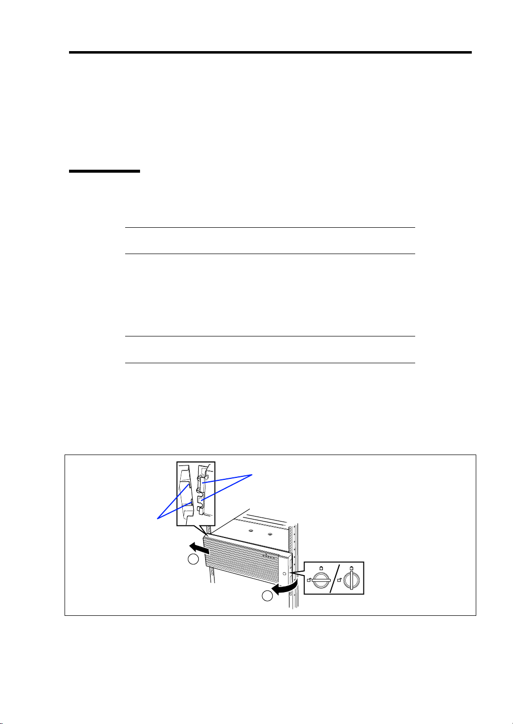
General Description 2-25
USING YOUR SERVER
This section describes basic operations of your server including how to use devices such as the
floppy disk drive and the CD-ROM drive. See Appendix B for notes on using the floppy disk, CDROM, and accessories including the keyboard and the mouse.
Front Bezel
Remove the front bezel to power on/off the server, to access the floppy disk drive and CD-ROM
drive, and to install/remove hard disks to the 3.5-inch hard disk bay.
IMPORTANT: To open the front bezel, you must unlock the door
with the provided security key.
Installing or Removing the Front Bezel
When turning the power of the server on/off, accessing to the floppy disk drive or CD-ROM drive,
or installing or removing a hard disk on or from the 3.5-inch hard disk bay, first remove the front
bezel.
IMPORTANT: The front bezel can be opened only when you unlock
it by using the attached security key.
1. Insert the attached security key into the key slot and turn the key to the front bezel side
with it pressed lightly to release the lock.
2. Hold the right end of the front bezel lightly to pull it toward you.
3. Slide the front bezel to the left a little to remove the tab from the frame and then remove
the front bezel from the server.
Frame
Ta b
2
1
To install the front bezel, latch the tab at the left side of the front bezel on the server frame.
After the installation, lock the front bezel by using the key for security.
Unlock Lock
Page 60

2-26 General Description
POWER Switch
Use the POWER switch to turn on/off the server.
Power On
Press the POWER switch on the front of the computer chassis.
The POWER/SLEEP lamp lights in green.
POWER/SLEEP lamp
IMPORTANT:
If the power cord is connected to a power control device such as a
UPS (Uninterruptive Power Supply), make sure that the power
control device is powered.
POWER switch
If the power cord is connected to the server, an initial diagnosis of
the hardware starts. The POWER switch does not work while in
diagnosis. Wait for about 10 seconds, then press the POWER
switch.
Do not turn off the server until characters following the "NEC" logo
appears on the screen.
Page 61

General Description 2-27
POST
POST (Power On Self-Test) is the self-diagnosis feature saved in the baseboard of the server.
When the power of the server is turned on, POST automatically runs to check the baseboard,
memory board, CPU, keyboard, and mouse. During POST messages indicating the starts of several
BIOS setup utilities may also appear.
At the shipment of the server, it is set to have the NEC logo appear on the display unit during POST.
Pressing Esc allows the information on the execution of POST to be displayed.
NOTE: The information on the result of diagnosis by POST can be
displayed from the start without the depression of Esc on the BIOS
menu. If you desire it, change the setting of "Boot-time Diagnosis
Screen" on "Advanced" of the BIOS configuration to "Enabled."
It may not always necessary to check the result of POST. Check the messages which may appear
during POST in the following cases:
Installation of the server
Suspicion of failure
Beep for many times in the period from power-on to OS start
Appearance of an error message on the display unit
Page 62

2-28 General Description
POST Flow
The flow of operations executed by POST is sequentially described below:
IMPORTANT: Depending on the system configuration, message
"Press Any Key" requesting key entry may appear on the display screen.
This is requested by BIOS on an installed optional board. See the
explanation described in the manual for the option and press any key.
1. After power-on, POST is activated to start the memory check. The message indicating the
counted size of the base memory and that of the additional memory appears at the upper
left corner of the display screen. In addition, the following message appears at the bottom
of the screen.
Press <ESC> to enter boot selection menu, <Space> to abort memory test
Press <F2> to enter SETUP, <F4> Service Partition, <F12> Network
NOTE: Pressing Space under the display of message "<Space> to
abort memory test" allows the memory test to be skipped.
It may take several minutes to complete the memory check depending on the size of the
memory installed in the server. Similarly, it may take about a minute to display the proper
information on the screen at rebooting.
2. Detects the SCSI controller built in the server and displays the message prompting the
start of the SCSI BIOS setup utility (without any key entry for several seconds, POST is
automatically continued). Press the proper keys according to the screen display.
Press <Ctrl> <A> for SCSISelect(TM) utility!
Now press Ctrl + A to start the utility. See Chapter 4 for the setting procedures and
features of the parameters.
For example, the SCSI BIOS setup utility must be used in the following cases:
Installation of an SCSI device in the 5.25-inch device bay
Connection of an external SCSI device (The removal of the SCSI cable for 5.25-inch
device in the server and the connection of the SCSI cable coming with the server (for
external connection) are required.)
Modification of SCSI device connections within the server
If the SCSI BIOS setup utility is terminated, the server runs POST from its start again.
When more than one SCSI controller boards are installed on the PCI bus of the server, the
messages indicating the starts of the SCSI BIOS setup utilities for the installed boards
appear in the following order:
PCI slot number PCI #1, PCI #2, PCI #3, PCI #4, PCI #5, PCI #6, PCI #7, and PCI #8.
Page 63
General Description 2-29
3. Displays the SCSI ID numbers used by the connected SCSI devices on the screen.
4. If one or more disk array controllers are installed, displays the message prompting you to
start the Disk Array BIOS setup utility.
Start the utility according to the message if you need to change the settings. Refer to the
manuals of the disk array controllers for details.
Without any entry, any of the following messages appears.
5. Displays the message notifying you of the detection of the CPU and the connected
keyboard and mouse.
6. Displays any of the following messages.
Pattern 1:
Press <ESC> to enter boot selection menu
Press <F2> to enter SETUP or <F12> to Network
Pattern 2:
Press <ESC> to enter boot selection menu
Press <F2> to enter SETUP, <F4> Service Partition, <F12> to Network
Or
Pattern 3:
Press <ESC> to enter boot selection menu
Press <F1> to resume, <F2> to enter Setup, <F12> to Network
Pattern 4:
Press <ESC> to enter boot selection menu
Press <F1> to resume, <F2> to enter Setup, <F4> Service Partition, <F12> Network
* The displayed message may vary depending on the device status.
Page 64

2-30 General Description
NOTE: The operation or utility to be started at each key entry is
described below. These operations or utilities may not always be
started.
Esc
Press Esc to display the boot menu at the end of POST. This menu
allows you to select the device to be started.
F2
Press F2 to start the BIOS setup utility. Start the utility to change
the setting of the server to that fit to the environment in which the
server is used. In general, the setting may not be particularly
changed by starting the utility excluding the case in which the
previous message accompanying by an error message appears. See
Chapter 4 for the setting procedures and features of the parameters.
Boot Menu
1. CD-ROM Drive
2. +Removable Devices
3. +Hard Drive
4. IBA 4.0.19 Slot 0003
5. IBA 1.0.17 Slot 0103
<Enter Setup>
F4
Press F4 to start the Off-line Maintenance Utility from the
maintenance partition. See Chapter 6 for the maintenance partition.
F12
Press F12 to run the network boot.
F1
If message "Press <F1> to resume" appears, an error is detected
during POST. See "Error messages during POST" for the
information on the messages and the proper actions against the
errors. If an error message appears, pressing F1 allows the BIOS
setup utility to be started.
7. When a password is set in the BIOS setup utility SETUP, the screen prompting you to
enter the password appears after the normal termination of POST.
The password can be entered for up to three times. If you enter the password incorrectly
all the time, the server cannot be started. In this case, turn off the power of the server, wait
for about 10 seconds, and then turn on the power to start the server again.
IMPORTANT: Set the password only after OS is installed.
8. Starts OS at the termination of POST.
Page 65

General Description 2-31
POST Error Messages
When POST detects an error, it displays an error message on the display unit screen. See Chapter
8 for POST error codes.
IMPORTANT: Take a note on the messages displayed before
consulting with your service representative. Alarm messages are
useful information for maintenance.
Power Off
Follow the procedure below to power off the server. If the power cord of the server is connected to
a UPS, refer to the manual that comes with the UPS or the manual for the application that controls
the UPS.
IMPORTANT: Always allow POST to complete before turning off the
server.
1. Shut down the OS.
2. Press the POWER switch on the front of the server.
The POWER/SLEEP lamp goes off.
3. Power off peripheral devices.
Page 66

2-32 General Description
SLEEP Switch
The SLEEP switch allows you to save almost all power of the server (power-saving mode or sleep
mode).
NOTE: To use the SLEEP switch, an OS supporting the sleep feature
is required. (Available for Windows 2000.)
SLEEP switch
Press the SLEEP switch on the front of the server to place the server in the power-saving mode.
(The POWER/SLEEP lamp blinks.) In the power-saving mode, the server retains the memory data
and the status of the previous operations.
To resume the original state, press the POWER switch. (It may take a little time to resume the
original state.)
POWER/SLEEP lamp
NOTE: The operational level in the power-saving mode depends on
the OS in use. (Available for Windows 2000.)
IMPORTANT: Do not change system configuration while turning into
the power-saving mode or in the power-saving mode. Otherwise, you
may fail to resume the original state.
Page 67

General Description 2-33
Floppy Disk Drive
Your server is provided with the 3.5-inch floppy disk drive on its front to write/read data to/from a
floppy disk.
Your server supports the following 3.5-inch floppy disks:
2HD floppy disk (double-sided high-density track type)
Stores data of 1.44MB.
2DD floppy disk (double-sided double-density track type)
Store data of 720KB.
Make sure that the server is powered (the POWER/SLEEP lamp is lit) before inserting a floppy disk
into the floppy disk drive.
When you completely insert the floppy disk into the floppy disk drive, the drive clicks and the eject
button on the floppy disk is slightly pushed out.
NOTES:
You cannot use a 1.2MB-formatted floppy disk.
When an unformatted floppy disk is inserted, the message notifying
that date read is not available and the message prompting formatting
are displayed. Refer to the manual that comes with the OS to
format the floppy disk.
If the floppy disk contains a system, powering on or restarting the
server with the floppy disk inserted boots the system from the
floppy disk.
To eject the floppy disk from the floppy disk drive, press the eject button.
NOTE: Make sure that the floppy disk access lamp is unlit before
ejecting the floppy disk. Ejecting the disk when the access lamp is lit
may destroy the disk data.
Page 68

2-34 General Description
NOTE: Use of the floppy disk
The floppy disk is an important data storage media with delicate
structure and requires care. Keep the following notes in mind to use
it:
Insert the floppy disk into the floppy disk drive gently as far as it
goes.
Attach the label to the correct position.
Do not write anything directly onto the disk surface with a pencil or
ball-point pen.
Do not open the shutter.
Do not use the floppy disk in a dusty place.
Do not place anything on the floppy disk.
Do not leave the floppy disk in a high-temperature place (e.g., place
exposed to direct sunlight or close to a heater).
Keep the floppy disk away from cigarette smoke.
Keep the floppy disk away from any liquid (e.g., water) and
chemicals.
Keep the floppy disk away from any magnetic objects (e.g.,
magnet).
Do not pinch the floppy disk with a paper clip or drop it.
Keep the floppy disk in a floppy disk case that protects it from
magnetism and dust.
A floppy disk has a write-protect switch that prevents the stored data
from accidental erasure. You can read data from a write-protected
floppy disk, but you cannot save data into the floppy disk or format
it. NEC recommends that you should write-protect any floppy disk
containing valuable data unless you are about to save data. To
write-protect a 3.5-inch floppy disk, use the write-protect switch
provided on its back.
Write-protect switch
Write
disable
The floppy disk is a very delicate storage media. Dust or thermal
Write
enable
changes, as well as operator's misconduct or sever failures, may
cause loss of data. To avoid loss of data, NEC recommends that
you should make a back-up copy of your valuable data on a regular
basis. (Make sure to make a back-up copy of every floppy disk
provided with the server.)
Page 69

General Description 2-35
CD-ROM Drive
Your server is provided with the CD-ROM drive on its front to read data from a CD-ROM (readonly compact disk). The CD-ROM provides larger and faster data read than the floppy disk.
CAUTION
Observe the following instructions to use the server safely. Failure to follow
these instructions may cause a fire, personal injury, or property damage. See
pages 1-3 to 1-8 for details.
■ Do not leave the tray ejected from the CD-ROM drive.
Set a CD-ROM on the CD-ROM drive in the following procedure.
1. Confirm that the power of the server is on (with the POWER/SLEEP lamp being lit in
green) before setting the CD-ROM on the CD-ROM drive.
2. Press the Eject button on the front of the CD-ROM drive.
The tray comes out a little.
3. Hold the tray lightly and pull it out toward you until the tray stops.
4. Put the CD-ROM on the tray carefully and securely with the date recorded surface facing
toward the tray.
Page 70

2-36 General Description
r
5. As shown in the figure below, hold the tray with a hand and press the CD-ROM with
fingers of another hand to make the hole of the CD-ROM fit to the rotor at the center of
the tray.
6. Push the front of the tray lightly to retract it into the drive.
IMPORTANT: If a noisy sound in driving the CD-ROM drive occurs
after setting a CD-ROM, set it again correctly.
Roto
Press this part of
CD-ROM.
To take out the CD-ROM from the CD-ROM drive, press the Eject button in the similar way in
setting the CD-ROM to make the tray go out.
If the access lamp is lit in orange, the CD is being accessed. Confirm that the access lamp is not lit
before pressing the Eject button.
As shown in the figure below, hold the tray with a hand and take the end of the CD-ROM lightly by
the fingers of another hand with the suppression of the rotor at the center of the tray to remove the
CD-ROM from the tray.
Page 71

General Description 2-37
After taking out the CD-ROM, return the tray into the drive.
When you fail to eject the CD-ROM tray with the Eject button and take out the CD-ROM from the
server, follow the procedure below.
1. Press the POWER switch to power off the server. (The POWER/SLEEP lamp goes off.)
2. Insert a metal pin of approximately 1.2 mm in diameter and 100 mm in length (a
straightened large paper clip will make a substitute) into the emergency hole on the upper
front of the CD-ROM drive and gently push it in until the tray is ejected.
IMPORTANT:
Do not use a toothpick or plastic stick that is easy to break.
If the above procedure does not let you take out the CD-ROM,
contact your service representative.
Emergency hole
3. Hold the tray and pull it out.
4. Take out the CD-ROM.
5. Push the tray back into position.
Page 72

2-38 General Description
NOTE: Use of the CD-ROM
Keep the following notes in mind to use the CD-ROM for the server:
For the disk which does not conform to the CD standard, the
playback of such a disk with the CD drive is not guaranteed.
Do not drop the CD-ROM.
Do not place anything on the CD-ROM or bend the CD-ROM.
Do not attach any label onto the CD-ROM.
Do not touch the signal side (nothing is printed on this side) with
your hand.
Place the CD-ROM with its printed side upward and gently put it on
the tray.
Do not scratch the CD-ROM or write anything directly on it with a
pencil or ball-point pen.
Keep the CD-ROM away from cigarette smoke.
Do not leave the CD-ROM in a high-temperature place (e.g., place
exposed to direct sunlight or close to a heater).
When dust or fingerprints are attached on the CD-ROM, wipe the
CD-ROM from its center to edge with a dry soft cloth slowly and
gently.
Use the CD cleaner to clean the CD-ROM. Do not use record
spray/cleaner, benzene, or thinner.
Keep the CD-ROM in a CD-ROM case when not in use.
If the CD-ROM emits large noise in the CD-ROM drive, remove the
CD-ROM and insert it back again.
Page 73

Chapter 3
Setting Up Your Server
This chapter describes how to set up your server appropriate for your system, on a step-by-step
basis.
Page 74
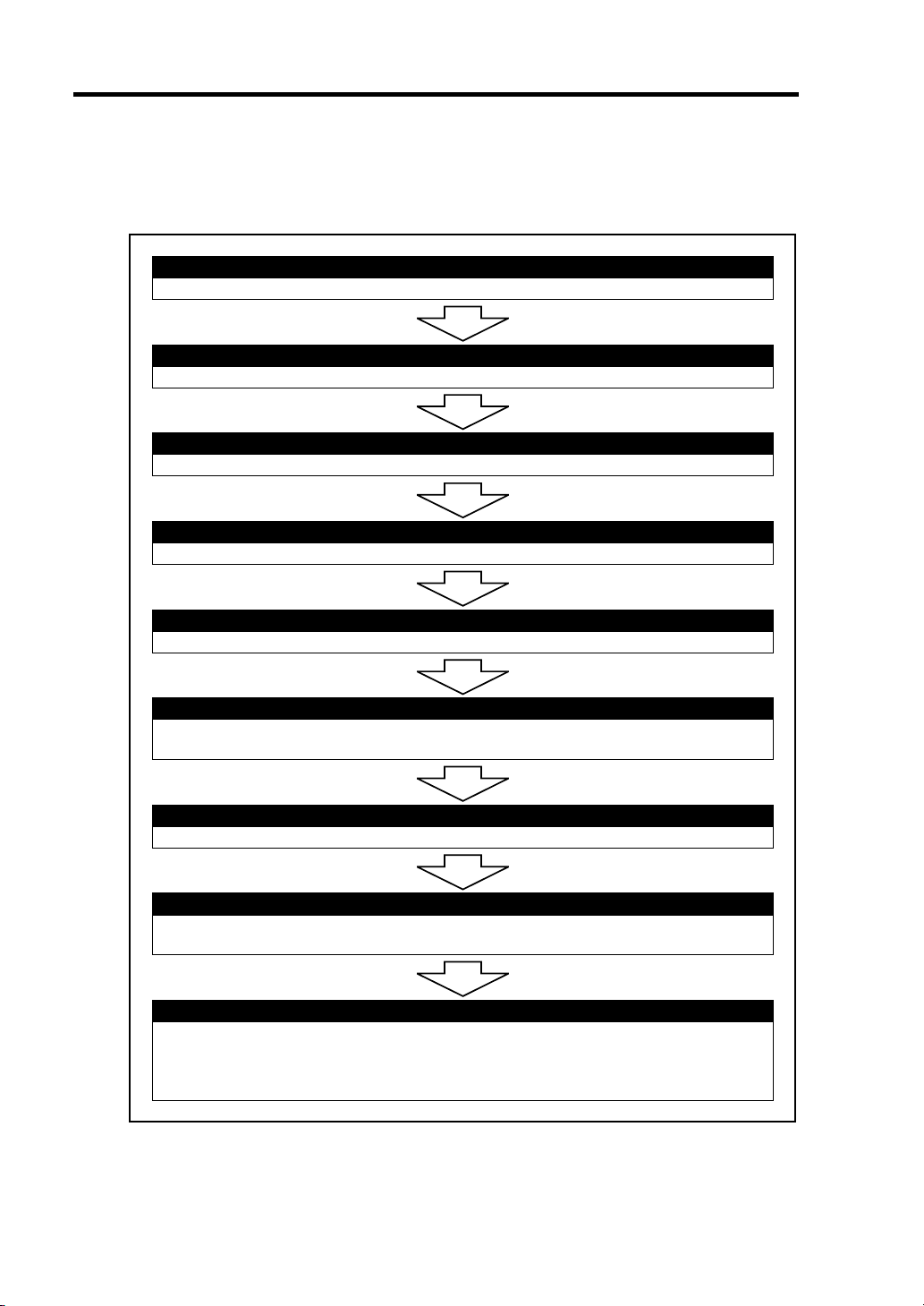
3-2 Setting Up Your Server
SETUP FLOW
Follow the flowchart below to set up the server.
Selecting a site
Select a suitable site for the server.
Unpacking the system
Unpack the server and accessories from the chipping carton box.
Assembling the rack-mount system
Assemble the 19-inch rack cabinet and install the server.
Connecting peripheral devices
Connect peripheral devices to the server.
Connecting the power cord
Connect the power cord to the server.
Turning on the server
Power on the server to start software setups. Setups depend on the optional internal
devices installed and the peripheral devices connected.
Installing the operating system
Install an operating system to the server. See Chapter 5.
Installing the utilities
Install the utilities in the provided NEC EXPRESSBUILDER CD-ROM.
See Chapter 6.
Making backup copies of system information
After all the system setup procedures are completed, make backup copies of system
information.
System information is required for recovering the server from the trouble or after
replacing the system board.
Page 75

Setting Up Your Server 3-3
SELECTING A SITE
Installation
Your server unit should be mounted in a standard EIA 19-inch rack cabinet.
Installation of Rack
Refer to the documentation attached to the rack or contact your service representative for rack
installation of the server unit.
WARNING
Observe the following instructions to use the server safely. Failure to follow
these instructions may result in death or serious personal injury. See pages 13 to 1-8 for details.
■ Do not use the server in any unapproved place.
CAUTION
Observe the following instructions to use the server safely. Failure to follow
these instructions may cause a fire, personal injury, or property damage. See
pages 1-3 to 1-8 for details.
■ Do not carry or install the server only by a single person.
■ Do not install the server where the load may be concentrated on a specific
point.
■ Do not install any component on the server only by a single person.
■ Do not pull out a device from the rack if the rack is unstable.
■ Do not leave more than one device being pulled out from the rack.
■ Do not provide the wiring exceeding the rating power.
Page 76

3-4 Setting Up Your Server
Before you begin the rack installation review the following guidelines.
Do Not:
Locate a rack in a narrow space that would inhibit devices from being pulled out from the
rack completely.
Locate the rack on a floor that cannot bear the total weight of the rack and devices
mounted in the rack.
Locate the rack in a place where stabilizers cannot be installed or where the rack can be
installed only after proper earthquake-resistant is constructed.
Locate the rack on an uneven or slanting floor
Locate the rack in an area that has drastic temperature change (near a heater, air
conditioner, or refrigerator).
Locate the rack where intense vibration may be generated.
Locate the rack where corrosive gases (sulfur dioxide, hydrogen sulfide, nitrogen dioxide,
chlorine, ammonia, ozone, etc) exist.
And also, locate it in the environment where the air (or dust) includes components
accelerating corrosion (ex. sulfur, sodium chloride) or conductive metals.
Place the rack on a carpet not subject to the anti-static process.
Locate the rack where some objects may fall on the rack.
Locate the rack near a device that is generating intense magnetic fields (such as a TV,
radio, broadcast/communication antenna, power transmission wire, and electromagnetic
crane.) If unavoidable, contact your service representative to request proper shielding.)
Locate the rack where the power cord of the server must be connected to an AC outlet that
shares other devices with large power consumption.
Locate the rack next to equipment that generates power noise (e.g., contact spark at
power-on/power-off of commercial power supply through a relay). If you must install
the server close to such equipment, request your service representative for separate power
cabling or noise filter installation.
Locate the rack where following conditions can not be satisfied.
Conditions for operation: *
Temperature: 10 to 35°C
Humidity: 20 to 80% (no condensation)
* It is recommended that the server should be used in a room where temperature is in the
range between 15 to 25°C.
Page 77

Setting Up Your Server 3-5
UNPACKING THE SYSTEM
When you receive your system, inspect the shipping containers prior to unpacking. If the shipping
boxes are damaged, note the damage, and if possible, photograph it for reference. After removing
the contents of the containers, keep the cartons and the packing materials. If the contents appear
damaged when you unpack the boxes, file a damage claim with the carrier immediately.
Page 78

3-6 Setting Up Your Server
ASSEMBLING THE RACK-MOUNT SYSTEM
This subsection provides the instructions for the rack-mount server unit into a standard EIA 19-inch
rack cabinet.
This subsection also describes the removal procedures for the rack mount server unit from the 19inch rack cabinet.
WARNING
Observe the following instructions to use the server safely. Failure to follow
these instructions may result in death or serious personal injury. See pages 13 to 1-8 for details.
■ Do not use any rack which does not conform to the relevant standard.
■ Disconnect the power cord(s) before installing or removing the server.
CAUTION
Observe the following instructions to use the server safely. Failure to follow
these instructions may cause a fire, personal injury, or property damage. See
pages 1-3 to 1-8 for details.
■ Do not leave more than one device being pulled out from the rack.
■ Do not lift the server only by a single person.
■ Always install the server in the specified place.
■ Do not install the server on the rack leaving the cover removed.
■ Do not pinch your finger with mechanical components.
Page 79

Setting Up Your Server 3-7
ESD Precaution
An electrostatic discharge (ESD) can damage disk drives, option boards, and other components. You
can provide some ESD protection by wearing an antistatic wrist strap attached to chassis ground
when handling system components.
Electronic devices can be easily damaged by static electricity. To prevent damage, keep them in
their protective packaging when they are not installed in your system.
Checking Components
Confirm that the following tools or components are provided to install the server on the rack.
1
6
5
12
13
7
8
14
15
23
11
9
10
16
17
18 19
4
Page 80

3-8 Setting Up Your Server
No. Item Q'ty Remarks
1 Front bezel 1
2 Slide rail assembly (L) 1 "L" is stamped on the rail.
3 Slide rail assembly (R) 1 "R" is stamped on the rail.
4 Cable arm 1
5 Adapter bracket 1
6 Handle (L) 1
7 Handle (R) 1
8 Arm bracket (700) 1
9 Arm bracket (900) 1
10 Arm stopper 1
11 Template 1
12 Tie-wrap 6 25 cm long.
13 Lock spring 1 Used to fix the power cords.
14 Screw-A 6 CPIMSx#8-32x6
15 Screw-B 7 CPIMSx6-32x8
16 Screw-C 14 CBIMS×5×10×3GF
17 Screw-D 6 PL-CPIMSx4x8x15BF
18 Washer-A 12 M5-14 (Assembled with Screw-C.)
19 Washer-B 4 PIWAx5x15BF (Assembled with Screw-D.)
Use one according to the distance between the
front and rear vertical mounting rails of your rack
cabinet.
Required Tools
#2 Phillips screwdriver and flat tip screwdriver are recommended for assembling the rack-mount
system.
Page 81

Setting Up Your Server 3-9
Installation Procedure
Install the server on the rack in the following procedure.
1. Define the position (height) at which the server is installed by using templates.
The templates have the same vertical size as the server. Put the templates on the front and
rear of the rack to locate them. The installation positions of the core nuts and slide rail
assembly are specified on the templates.
Icons showing the positions at which
core nuts are installed
Template (front) Template (rear)
Page 82

3-10 Setting Up Your Server
2. Install the core nuts coming with the rack at the positions defined by the templates.
Install four core nuts (two for each of left and right sides) on the front face of the rack
from the inner side. The server is fixed to the rack with the core nuts, four screws C, and
four washers A.
Install two core nuts from the inner side of the rear of the rack (at the left side when you
faces the rear of the rack). When the core nuts are installed on a rack with the distance
between the front and rear mount faces of 700 or 743 mm, fix the arm bracket (700) to the
core nuts.
Hang the lower clip of a core nut on the proper rectangular hole and insert the upper clip
into the hole using a flat-tip driver or a similar tool.
IMPORTANT: Install the core nuts so that the clips are located at the
top and bottom. If any core nut is installed with the clips located at the
left and right ends, the server may be dropped to cause it to be defected
and also people to be injured severely.
3. Pull out either one of the inner rails from the slide rail assembly.
If the inner rails are pull out, these are locked once at a position of the way. Push the
release lever to release the lock and pull out the inner rails further.
Inner rail
Slide rail assembly
Release lever
Page 83

Setting Up Your Server 3-11
r
4. Install an inner rail on one side of the server with three screws A in the direction shown in
the figure.
Release lever
NOTE: Each inner rail may be used at either of the left and right sides.
However, use the proper inner rail to each slide rail assembly from
which the rail has been removed so that the direction of the inner rail
can be fit to the slide rail assembly.
5. Install the other inner rail on the other side of the server by steps 3 and 4 above.
6. Install handles R and L on the front of the server with four screws B.
NOTE: The left handle is different from the right handle in shape.
Check the shape of each handle. The handle (L) has the frame on which
the tab of the front bezel is hung.
Handle (L)
Frame on which tab
is hung
Left side of server
Handle (R)
Right side of serve
Page 84
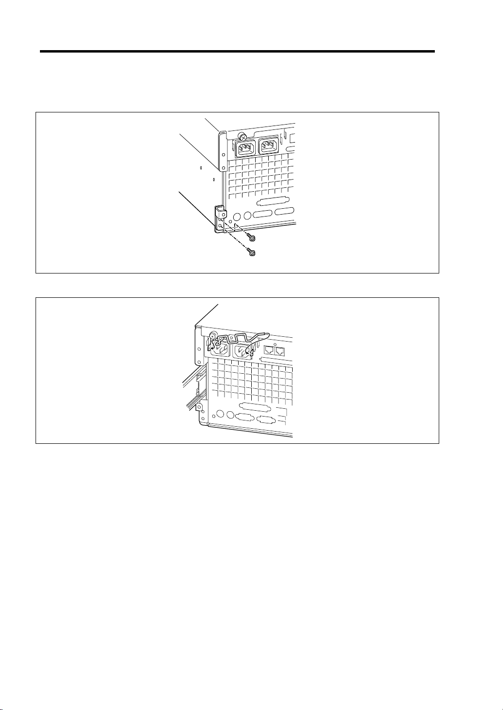
3-12 Setting Up Your Server
7. After removing the screw located on the rear of the server, install the adapter bracket on
the rear of the server with a single screw B and a screw removed before.
Screw removed from the rear of the server.
Screw B
8. Install the lock spring to the holes at the both sides of the AC inlet.
Page 85

Setting Up Your Server 3-13
9. Loosen the three screws with which the slide bracket of the slide rail assemble is fixed.
This step is required to match the length of the slide rail assembly with the depth of the
rack (distance between the front and rear supports). If the three screws are loosened, the
slide bracket may be slid in the front or rear direction.
Screws
10. Locate the slide rail assembly on the right side of the rack frame at the position defined by
the template.
Stamp of two circles
(placed in 5U)
Stamp (located at the upper
right position of screw hole)
Screw hole
NOTES:
Check the direction of installing the slide rail assembly.
– Make the bracket face facing the outside of the rack.
– Locate the side with the slide bracket at the rear of the rack.
The front and rear supports of the rack have rectangular holes for
screw fastening. For the NEC rack, round stamps are provided in 1U.
As shown in the figure, locate the slide rail assembly so that a stamp
is positioned at the upper right of the top screw hole of the slide rail
assembly.
Page 86

3-14 Setting Up Your Server
11. Fix the slide rail assembly with four screws C (two on each of the front and rear sides) and
four washers A (two on each of the front and rear sides).
NOTES:
Make sure that the frame tips on the slide rail assembly are contact
to the rectangular hole frames of the rack properly and the four
screw holes of the rail can be seen through the mating rectangular
holes of the rack
Check that the slide rail assembly is located to the level.
12. Fasten the screws loosen in step 9 to fix the slide bracket.
13. Install the other slide rail assembly on the left side of the rack in the same procedure as
that described by steps 9 to 12 above.
NOTE: Make sure that the slide rail assembly is installed at the same
level as the other slide rail assembly already installed. For installing the
server to the rack that has distance between the mount faces at the front
and rear faces of the rack being 743 mm or longer, fix the slide rail
assembly and arm stopper together with two screws C. (In this case,
washers A is not necessary.)
Page 87

Setting Up Your Server 3-15
14. Hold the server by more than one person to mount it on the rack.
CAUTION
Observe the following instructions to use the server safely. Failure to follow
these instructions may cause a fire, personal injury, or property damage. See
pages 1-3 to 1-8 for details.
■ Do not lift the server only by a single person.
■ Do not pinch your fingers with mechanical component.
■ Do not push the release lever with fingers.
Insert the rails on the side faces of the server into the slide rail assemblies securely and
then push the server slowly and carefully. If the server is locked on the way, push the
server slowly with the depression of the release lever on each of the left and right sides.
Bearing rail
Slide rail assembly
Plastic portions
Inner rail
Mating portion
Release lever
IMPORTANT: Push each release lever using a driver or a similar tool.
Pushing a release lever with your fingers may cause the fingers to be
caught and thus injured.
Page 88

3-16 Setting Up Your Server
NOTE: The slide rail assembly installed in the rack contains a slide
rail called the bearing rail. The bearing rail can be moved freely in the
slide rail assembly. To install the server in the rack securely, slide the
bearing rail to the front of the rack to put the plastic components at the
tip of the rail and the inner rail into the server.
At the first installation, you may feel strong friction in pushing because the mechanical
components cannot be completely engaged with each other. Push the server intensely.
NOTE: While the server is pushed into the rack, the server may be
locked and thus cannot be pushed any more. This is because the lock
lever on the rail prohibits the server from being pushed into the rack
any more. Set the lock lever to be on the level to release the lock and
then push the server into the rack slowly.
15. Install the cable arm on the rear of the server with two screws B.
Drive two screws B to the rear of the server and the adapter bracket temporarily, insert the
groove of the cable arm to the screws, and securely fasten the screws driven temporarily
Cable arm
Page 89

Setting Up Your Server 3-17
A
16. Install the arm bracket on the mount face at the rear of the rack or the slide rail assembly.
Mount face
Mount face
NOTE: Two types of arm brackets are provided to be fit to any
distance between the front and rear mount faces of the rack.
Use arm bracket (700) if the distance between the front and rear mount
faces of the rack is 700 or 743 mm. Use arm bracket (900) for the rack
having the depth of 760 or 900 mm.
For the distance between the mount faces at the front and rear of the rack being 700 or 743
mm:
Fix the arm bracket (700) to the core nuts installed on the mount face of the rear of the
rack with two screws C.
Core nut installation
position
rm bracket (700)
Page 90

3-18 Setting Up Your Server
A
A
For the distance between the mount faces at the front and rear faces of the rack being 760
mm:
Fix arm bracket (900) to the screw holes nearest to the rear face among the rear holes on
the slide rail assembly using two screws D.
rm bracket (900)
For the distance between the mount faces at the front and rear faces of the rack being 900
mm:
Fix arm bracket 900 to the screw holes nearest to the front face among the rear holes on
the slide rail assembly using two screws D.
rm bracket (900)
Page 91

Setting Up Your Server 3-19
A
A
17. Install the other end of the cable arm on the arm bracket installed in step 16.
For the distance between the mount faces at the front and rear of the rack being 700 mm:
Fix the arm bracket with two screws D and two washers B at the position shown in the
figure below.
rm bracket (900)
For the distance between the mount faces at the front and rear of the rack being 743 mm:
Fix the arm bracket with four screws D and four washers B at the position shown in the
figure below.
rm bracket (900)
Page 92

3-20 Setting Up Your Server
A
For the distance between the mount faces at the front and rear of the rack being 760 or 900
mm:
Fix the arm bracket with four screws D and four washers B at the position shown in the
figure below (the figure below shows the example with the distance between the mount
faces at the front and rear of the rack being 900 mm).
rm bracket (900)
18. Push the server into the rack once to check the installation position.
NOTE: Make sure that the four screw holes at the upper left and right
sides on the front of the server are fit to the core nuts installed in step 2.
If the four positions are not fit at all, the slide rail assembly or the core
nuts may be installed incorrectly. If so, the adjacent units cannot be
installed without clearance. Confirm the installation positions and make
the reinstallation from the first step.
19. Pull out or push the server into the rack for several times to confirm that the slides move
smoothly.
20. Fix the server to the rack with four screws C and four washers A.
Screws C and Washers A
Page 93

21. Install the front bezel.
Now the installation is completed.
Setting Up Your Server 3-21
Page 94

3-22 Setting Up Your Server
Removal Procedure
More than one person should remove the server from the rack.
CAUTION
Observe the following instructions to use the server safely. Failure to follow
these instructions may result in death or serious personal injury. See pages 1-3
to 1-8 for details.
■ Do not lift the server only by a single person.
■ Do not pinch your finger with mechanical components.
■ Note high temperature.
■ Do not pull out a device from the rack if the rack is unstable.
■ Do not leave more than one device being pulled out from the rack.
1. After confirming that the server is off-powered, remove the power cords and all interface
cables connected to the server.
2. Loosen two screws with which the cable arm is fixed to the rear of the server to remove
the cable arm from the server.
Screws
3. Release the security lock to remove the front bezel.
Cable arm
Page 95
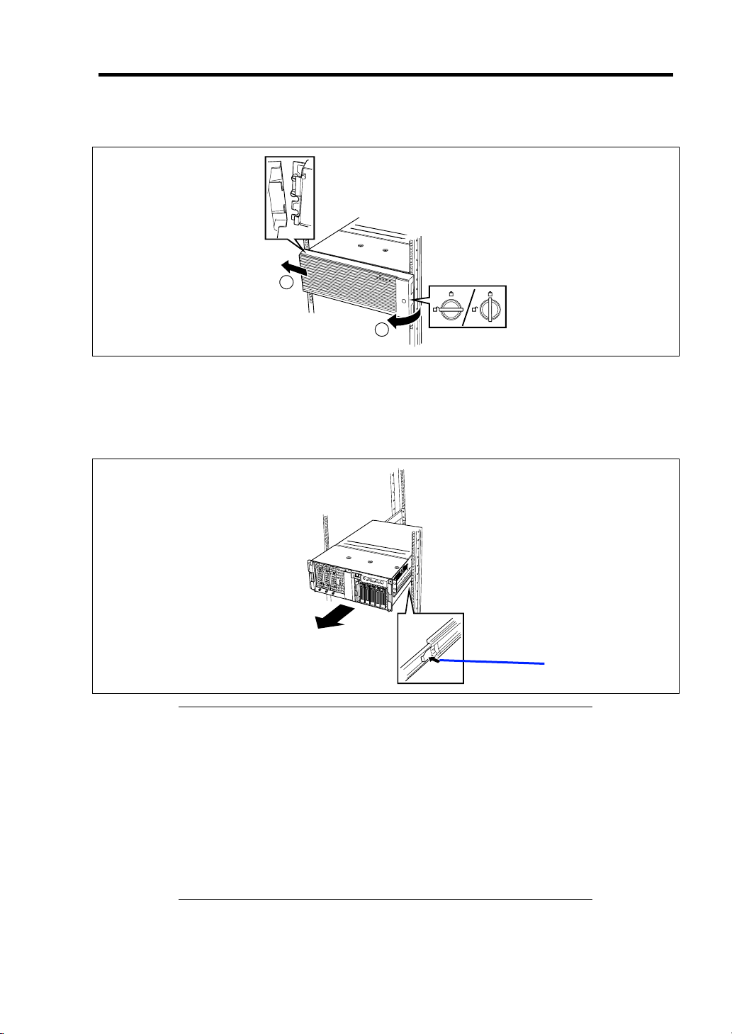
Setting Up Your Server 3-23
4. Remove four screws C located at both side of the front face of the server to fix it.
2
1
Unlock Lock
5. Hold the handle to pull out the server from the rack slowly and carefully.
The server clicks to be latched.
6. Push the left and right release levers to release the latch and then pull out the server from
the rack slowly.
Release lever
IMPORTANT:
Push each release lever using a driver or a similar tool. Pushing a
release lever with your fingers may cause the fingers to be caught
and thus injured.
Pull out the server slowly with the bottom supported by more than
one person.
Secure the power cord(s) and interface cables with a lock spring.
Form the power cord with a slight slack at the AC inlet of the server.
This is to prevent the power cord from coming off when the server
is pulled out from the rack.
Do not apply any pressure to the plug of the power cord.
See the "Installation procedure" when the mechanical components of the rack are removed also.
Page 96

3-24 Setting Up Your Server
CONNECTING PERIPHERAL DEVICES
Connect peripheral devices to the server. The server is provided with connectors for wide variety
of peripheral devices on its front and rear. The figure on the next page illustrates available
peripheral devices for the server in the standard configuration and locations of the connectors for the
devices.
CAUTION
Observe the following instructions to use the server safely. Failure to follow
these instructions may cause a fire, personal injury, or property damage. See
pages 1-3 to 1-8 for details.
■ Do not connect any interface cable with the power cord of the NEC Express
Server plugged to a power source.
■ Do not use any unauthorized interface cable.
IMPORTANT:
Power off the server and a peripheral device before connection.
Connecting a powered peripheral device to the powered server will
cause malfunctions and failures (excluding the USB device).
To connect a third-party peripheral device or interface cable to the
server, consult with your service representative for availability of
such a device or cable. Some third-party devices may not be used
for the server.
The "100BASE-TX/10BASE-T connector" and the "serial port B
connector" of this server have the same shape. Be careful not to
connect a cable to a wrong connector.
A leased line cannot be connected directly to the serial port
connectors.
Secure the power cord(s) and interface cables with a lock spring.
Form the cables in such a way that they will not come into contact
with the door or the guide rails on the sides of the server.
Page 97

Setting Up Your Server 3-25
(e.g.,
)
(e.g.,
)
Device with the serial
interface
(e.g., Management PC)
FRONT
Finally connect the provided
power cord to the receptacle.
If connecting the server to UPS,
see the explanation below.
When an optional power
supply unit is additionally
installed
Device with the USB Interface
keyboard
Printer with the
parallel interface
Device with the ICMB interface
Device with the
REAR
B
serial interface
A
100BASE TX/
10BASE-T
*2
SCSI device
Keyboard
Mouse
1
2
1000BASE-T
100BASE TX/
10BASE-T
Hub
(multiport repeater)
Device with the serial interface
(e.g., modem)
Direct connection to the private
telephone line is prohibited.
Display unit
Device with USB interface
Network system
on LAN
(connected
via a hub)
terminal adapter
*1 To connect the external SCSI devices, change the baseboard cable connection.
*2 A leased line cannot be connected directly to this connector. The console of a management PC can be connected to
only serial port B. (BIOS setting required) Connect the console to only serial port B on either the front or rear panel.
To connect the rear side serial port B, change the baseboard cable connection with rear side serial cable that comes
with the server.
*1
Page 98

3-26 Setting Up Your Server
Connection to Serial Ports
Various types of serial devices can be connected to the RJ-45 serial ports on the front or rear panels
of the server. Some devices require the setting of the jumper pin (JP25) on the baseboard to be
changed according to the DCD/DSR signal specification, or they need to be connected via an
optional serial port conversion cable.
There are two kind of cables in optional serial portconversion cable set. The "R" label is attached to
one cable (used with this server), and the "F" label is attached to the other (not used with this server).
Regarding to this cable set, contact your service representative for details.
IMPORTANT: Inter-equipment potential difference may cause a
server failure. Be sure to turn off the server and the connectiondestination equipment and disconnect the power cord before
connecting/disconnecting the cable to/from the serial port.
The figure below shows the location of the jumper pin (JP25). For methods to dismount the cover
and other internal components, see Chapter 9.
* Factory-set
: Strapped
Page 99

Setting Up Your Server 3-27
Connection between the RJ-45 Serial Port and a Modem
To connect a modem to the RJ-45 serial port, use the optional "serial port conversion cable" with the
"R" label attached. Be careful not to use the other one with the "F" label attached. Set the jumper
pin to "DCD+DSR" (factory-set).
IMPORTANT: Make sure of the icon of the server, and be sure to
connect the cable to serial port B. Be careful not to connect to a LAN
port by mistake.
To prevent wrong connection, write "LAN port" on a tag and put the tag
to the connector of the LAN cable that is to be connected to this server.
Wiring block diagram of the internal cables:
RJ-45 serial port Serial port conversion
cable (with the R label
attached)
DTE-DCE straight cable DCE
Page 100

3-28 Setting Up Your Server
Connection between the RJ-45 Serial Port and a UPS
To connect a UPS to the RJ-45 serial port, use the optional "serial port conversion cable" with the
"R" label attached. Be careful not to use the other one with the "F" label attached. Set the jumper
pin to "DCD+DSR" (factory-set).
IMPORTANT: Make sure of the icon of the server, and be sure to
connect the cable to serial port B. Be careful not to connect to a LAN
port by mistake.
To prevent wrong connection, write "LAN port" on a tag and put the tag
to the connector of the LAN cable that is to be connected to this server.
Wiring block diagram of the internal cables:
RJ-45 serial port Serial port conversion
cable (with the R label
attached)
UPS connection cable DCE
 Loading...