

Page 1

Express5800 140He
User’s Guide
Page 2

Page 3

000
Proprietary Notice and Liability Disclaimer
The information disclosed in this document, including all designs and related materials, is the
valuable property of NEC Computers International and/or its licensors. NEC Computers
International and/or its licensors, as appropriate, reserve all patent, copyright and other
proprietary rights to this document, including all design, manufacturing, reproduction, use, and
sales rights thereto, except to the extent said rights are expressly granted to others.
The NEC Computers International product(s) discussed in this document are warranted in
accordance with the terms of the Warranty Statement accompanying each product. However,
actual performance of each product is dependent upon factors such as system configuration,
customer data, and operator control. Since implementation by customers of each product may
vary, the suitability of specific product configurations and applications must be determined by
the customer and is not warranted by NEC Computers International.
To allow for design and specification improvements, the information in this document is subject
to change at any time, without notice. Reproduction of this document or portions thereof without prior written approval of NEC Computers International is prohibited.
Trademarks
NEC ESMPRO and NEC EXPRESSBUILDER are trademarks of NEC Corporation.
Microsoft, Windows, Windows Server, and MS-DOS are registered trademarks or trademarks of
Microsoft Corporation in the United States and other countries.
Intel and Pentium are registered trademarks of Intel Corporation.
Xeon is a trademark of Intel Corporation.
Novell and NetWare are registered trademarks of Novell, Inc. of the United States.
Datalight is a registered trademark of Datalight, Inc.
ROM-DOS is a registered trademark of Datalight, Inc.
AT is a registered trademark of International Business Machines Corporation in the United States and
other countries.
Adaptec and its logo is a registered trademark of Adaptec, Inc. of United States.
SCSISelect is a trademark of Adaptec, Inc. of the United States.
Adobe, Adobe logo, and Acrobat are trademarks of Adobe Systems Incorporated.
DLT and DLTtape are trademarks of Quantum Corporation of the United States.
All other product, brand, or trade names used in this publication are the trademarks or registered
trademarks of their respective trademark owners.
rev 0.0 September 2005
Copyright 2005
NEC Computers International B.V.
Nieuweweg 279
6603 BN Wijchen
The Netherlands
All Rights Reserved
Page 4

This page is intentionally left blank.
Page 5
Keep this User’s Guide at hand for quick reference at anytime necessary.
SAFETY INDICATIONS
Follow the instructions in this User’s Guide for your safety to use the server.
The server contains components with possible danger, hazards that may cause by ignoring warnings, an d preventive
actions against such hazards.
Server components with possible danger are indicated with a warning label placed on or around them as well as
described in this User’s Guide.
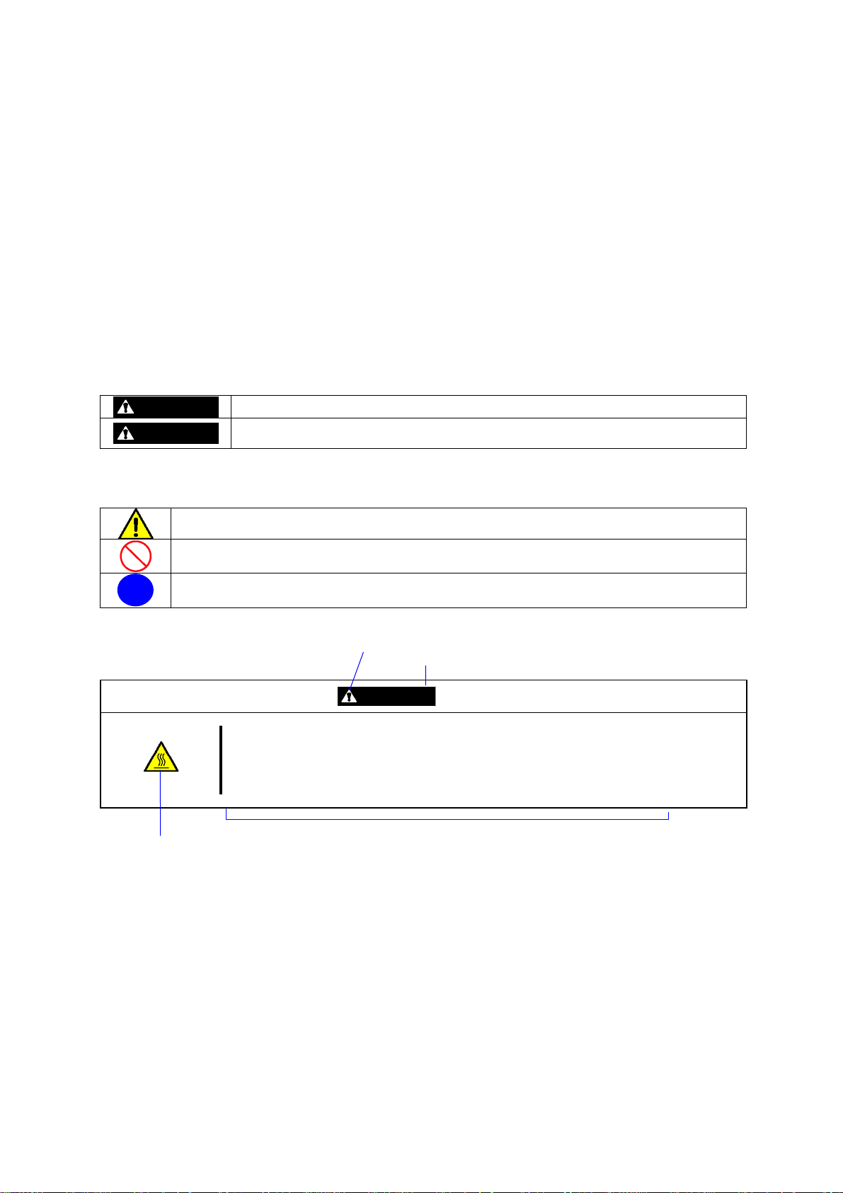
In the User’s Guide or warning labels, "WARNING" or "CAUTION" is used to indicate a degree of danger. These terms
are defined as follows:
WARNING
CAUTION
Precautions and notices against hazards are presented with one of the following three symbols. T he individual symbols
are defined as follows:
This symbol indicates the presence of a hazard.
An image in the symbol illustrates the hazard type. (Attention)
This symbol indicates prohibited actions. An image in the symbol illustrates a particular prohibited
action. (Prohibited Action)
This symbol indicates mandatory actions. An image in the symbol illustrates a mandatory action to
avoid a particular hazard. (Mandatory Action)
(Example)
High temperature.
Term indicating a degree of danger
Symbol indicating a prohibited
action (may not always be
indicated)
Indicates the presence of a hazard that may result in death or serious personal injury.
Indicates the presence of a hazard that may cause minor personal injury, including
burns, or property damage.
Symbol to draw attention
CAUTION
Immediately after the server is powered off, its internal components such as hard disks are
very hot. Leave the server until its internal components fully cool down before
installing/removing any component.
Description of the danger
Page 6
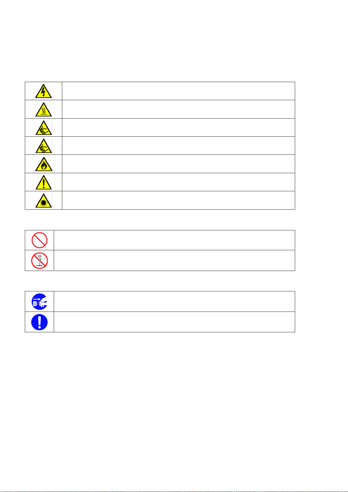
SYMBOLS USED IN THIS USER'S GUIDE AND WARNING LABELS
Attentions
Indicates that improper use may cause an electric shock.
Indicates that improper use may cause personal injury.
Indicates that improper use may cause fingers to be caught.
Indicates that improper use may cause the clip of a hand.
Indicates that improper use may cause fumes or fire.
Indicates a general notice or warning that cannot be specifically identified.
Indicates that improper use may cause loss of eyesight due to laser beam.
Prohibited Actions
Indicates a general prohibited action that cannot be specifically identified.
Do not disassemble, repair, or modify the server. Otherwise, an electric shock or fire may be caused.
Mandatory Action
Unplug the power cord of the server. Otherwise, an electric shock or fire may be caused.
Indicates a mandatory action that cannot be specifically identified. Make sure to follow the
instruction.
SAFETY INDICATIONS BY COLOUR OF THE PARTS
Only green area is available for hot swap or hot plug operation. To avoid electric shock, disconnect all AC power cords
before accessing to other parts especially blue area inside the system.
Page 7

NOTE: This equipment has been tested and found to comply with the limits for a Class A digital device, pursuant to
Part 15 of the FCC Rules. These limits are designed to provide reasonable protection against harmful interference when
the equipment is operated in a commercial environment. This equipment generates, uses, and can radiate radio
frequency energy and, if not installed and used in accordance with the instruction manual, may cause harmful
interference to radio communications. Operation of this equipment in a residential area is likely to cause harmful
interference in which case the user will be required to correct the interference at his own expense.
CE Statement
Warning: This is a Class A product. In domestic environment this product may cause radio interference in which case
the user may be required to take adequate measures (EN55022).
CLASS 1
LASER PRODUCT
This system is classified as a CLASS 1 LASER PRODUCT. This
label is located on the internal CD-ROM installed in your system.
Page 8

Momentary voltage drop prevention:
This product may be affected by a momentary voltage drop caused by lightning. To prevent a momentary voltage drop,
an AC uni nt erruptible power supply (UPS) unit shoul d be used.
Notes:
(1) No part of this manual may be reproduced in any form without the prior written permission of NEC Corporation.
(2) The contents of this User's Guide may be revised without prior notice.
(3) The contents of this User’s Guide shall not be copied or altered without the prior written permission of NEC
Corporation.
(4) All efforts have been made to ensure the accuracy of all information in this User ’s Guide. If you notice any part
unclear, incorrect, or omitted in this User’s Guide, contact the service representative where you purchased this
product.
(5) NEC assumes no liability arising from the use of this product, nor any liability for incidental or consequential
damages arising from the use of this User’s Gui de rega rdl ess of Item (4).
Page 9

PREFACE
Welcome to the Express5800/140He server.
The Express5800 server holds powerful performance and employs the latest technology to implement a computer for
the next generation. With its potential capabilities, the server may be used as the workstation PC that configures a
client-server system and provides high-speed processing and superior reliability.
Read this User’s Guide thoroughly to fully understand handling of the server and appreciate its functions to the
maximum extent.
i
Page 10

ii
ABOUT THIS USER'S GUIDE
This User’s Guide is a guide for proper setup and use of the server.
This User’s Guide also covers useful procedures for dealing with difficulties and problems that may arise during setup
or operation of the server. Keep this manual for future use.
The following describes how to proceed with this User’s Guide.
How to Use This User's Guide
To aid you in finding information quickly, this User’s Guide contains the following information:
Chapter 1 Notes on Using Your Server
includes information that needs attention to use the server. Make sure to read this chapter before setting up and
using the server.
Chapter 2 General Description
includes information necessary to use the server, such as names and functions of its components, handling of
the floppy disk and CD-ROM drives. It also includes requirements and advisory information for transfer and
disposal of the server.
Chapter 3 Setting Up Your Server
tells you how to select a site, unpack the system, make cable connections, and power on your system.
Chapter 4 Configuring Your Server
tells you how to configure the system and provides instructions for running the BIOS Setup Utility and the
MegaRAID Configuration Utility, which is used to configure SCSI devices in your system. This chapter also
provides information on I/O board jumper settings.
Chapter 5 Installing the Operating System with Express Setup
describes how to install the operating system.
Chapter 6 Installing and Using Utilities
describes how to install the utilities for the server. It also includes a description on using the attached "NEC
EXPRESSBUILDER" CD-ROM.
Chapter 7 Maintenance
provides you with all the information necessary to maintain successful operation of the server. This chapter also
includes a description on relocating and storing the server.
Chapter 8 Troubleshooting
contains helpful information for solving problems that might occur with your system.
Chapter 9 Upgrading Your Server
provides you with instructions for upgrading your system with an additional processor, optional memory, optional
add-in cards, hard disk drives, peripheral devices, and power supply.
Appendix A Specification
provides specifications for your server.
Appendix B Other Precautions
provides supplementary notes on using the server.
Page 11

Appendix C IRQ and I/O Port Address
provides a list of factory-set IRQs and I/O port addresses assigned.
Appendix D Installing Windows Server™ 2003 x64 Editions
describes how to install Microsoft® Windows Server™ 2003 x64 Editions without using Express Setup. Using
the Express Setup tool is recommended for installing Windows Server™ 2003 x64 Editions. See Chapter 5 for
details.
Appendix E Installing Windows Server 2003
describes how to install Microsoft® Windows Server™ 2003 without using Express Setup. Using the Express
Setup tool is recommended for installing Windows Server™ 2003. See Chapter 5 for details.
Appendix F Product Configuration Record Table
provides a table to be filled with your server configuration.
Text Conventions
The following conventions are used throughout this User’s Guide. For safety symbols, see "SAFETY INDICATIONS"
provided earlier.
iii
IMPORTANT:
NOTE:
Items that are mandatory or require attention when using the server.
Notes give important information about the material being described.
IN THE PACKAGE
The carton contains various accessories, as well as the server itself. See the packing list to make sure that you have
everything and that individual components are not damaged. If you find any component missing or damaged, contact
your service representative.
Store the provided accessories in a designated place for your convenience. You will need them to install
optional devices or troubleshoot the server, as well as to set it up.
Make a backup copy of each provided floppy disk, if any. Store the original disk as the master disk in a
designated place, and use its copy.
Improper use of any provided floppy disk or CD-ROM may alter your system environment. If you find
anything unclear, immediately ask your service representative for help.
Page 12

iv
CONTENTS
Preface ...........................................................................................................................................................................i
About This User's Guide...............................................................................................................................................ii
In the Package..............................................................................................................................................................iii
Chapter 1 ...........................................................................................................................1-1
Notes on Using Your Server ............................................................................................ 1-1
Warning Labels..........................................................................................................................................................1-2
Safety Notes...............................................................................................................................................................1-3
General ..................................................................................................................................................................1-3
Power Supply and Power Cord Use.......................................................................................................................1-4
Installation, Relocation, Storage, and Connection.................................................................................................1-5
Cleaning and Working with Internal Devices........................................................................................................1-6
During Operation...................................................................................................................................................1-7
For Proper Operation.................................................................................................................................................1-8
Transfer to Third Party...............................................................................................................................................1-9
Consumables ............................................................................................................................................................1-10
Disposal of the Server..............................................................................................................................................1-10
User Support............................................................................................................................................................1-11
Chapter 2 ...........................................................................................................................2-1
General Description..........................................................................................................2-1
Overview....................................................................................................................................................................2-2
External Vie w........................................................................................................................................................2-3
Front View (with the Front Door Open)................................................................................................................2-4
Front View (Switch and LED Panel).....................................................................................................................2-5
Rear Vie w..............................................................................................................................................................2-6
Internal View.........................................................................................................................................................2-8
I/O Board...............................................................................................................................................................2-9
Processor Board...................................................................................................................................................2-10
Memory Board.....................................................................................................................................................2-11
Management LAN Board....................................................................................................................................2-11
Standard Features.....................................................................................................................................................2-12
Power Supplies....................................................................................................................................................2-13
Peripheral Bays....................................................................................................................................................2-13
Recovering BIOS Data........................................................................................................................................2-15
SAF-TE Logic.....................................................................................................................................................2-15
System Cooling ...................................................................................................................................................2-15
System Board Features........................................................................................................................................2-16
Security................................................................................................................................................................2-18
EXPRESSBUILDER...........................................................................................................................................2-19
ESMPRO.............................................................................................................................................................2-20
Off-line Maintenance Utility...............................................................................................................................2-20
System Diagnostic Utility....................................................................................................................................2-20
DianaScope..........................................................................................................................................................2-20
Using Y our Server....................................................................................................................................................2-21
Security Lock (Locking the Front Cover)............................................................................................................2-21
POWER Switch...................................................................................................................................................2-22
POST...................................................................................................................................................................2-22
SLEEP Switch.....................................................................................................................................................2-26
Floppy Disk Drive............................................................................................................................................... 2-27
CD-ROM Drive...................................................................................................................................................2-28
Chapter 3 ...........................................................................................................................3-1
Page 13

Setting Up Your Server .................................................................................................... 3-1
Setup Flow................................................................................................................................................................. 3-2
Selecting a Site .......................................................................................................................................................... 3-3
Unpacking the System............................................................................................................................................... 3-5
Connecting Peripheral Devices.................................................................................................................................. 3-6
Connecting Power Cord............................................................................................................................................. 3-8
Turning On the Server............................................................................................................................................. 3-10
Installing Operating System .................................................................................................................................... 3-12
Installing Utilities .................................................................................................................................................... 3-12
Making Backup Copies of System Information.......................................................................................................3-12
Chapter 4........................................................................................................................... 4-1
Configuring Y our Server.................................................................................................. 4-1
System BIOS ~ SETUP ~.......................................................................................................................................... 4-1
Starting SETUP Utility.......................................................................................................................................... 4-2
Description of On-Screen Items and Key Usage................................................................................................... 4-3
Configuration Examples........................................................................................................................................ 4-4
Menu and Parameter Descriptions ........................................................................................................................ 4-7
Disk Array Configuration – MegaRAID Configuration Utility –......................................................................... 4-29
Notes on Using.................................................................................................................................................... 4-29
Starting Configuration Utility..............................................................................................................................4-30
Menu Tree........................................................................................................................................................... 4-31
Operating Procedures for Configuration Utility................................................................................. ................. 4-34
Remote Management Function................................................................................................................................ 4-49
Default Network Settings.................................................................................................................................... 4-49
Server Setup........................................................................................................................................................ 4-49
Configuring Management PC.............................................................................................................................. 4-50
Using Remote Management Console.................................................................................................................. 4-51
Configuring I/O Board Jumpers.............................................................................................................................. 4-77
v
Chapter 5........................................................................................................................... 5-1
Installing the Operating System with Express Setup................................................... 5-1
About Express Setup ................................................................................................................................................. 5-2
Microsoft® Windows Server™ 2003........................................................................................................................ 5-3
Installation Notice.................................................................................................................................................5-3
Setup Flow ............................................................................................................................................................ 5-6
Installing Windows Server 2003........................................................................................................................... 5-7
Installing and Setting Device Drivers..................................................................................................................5-10
Setting for Solving Problems .............................................................................................................................. 5-15
Installing Maintenance Utilities .......................................................................................................................... 5-18
Updating the System........................................................................................................................................... 5-18
Making Backup Copies of System Information.................................................................................................. 5-18
Exceptional Setup................................................................................................................................................ 5-19
Chapter 6........................................................................................................................... 6-1
Installing and Using Utilities ........................................................................................... 6-1
EXPRESSBUILDER................................................................................................................................................. 6-2
EXPRESSBUILDER for DOS-Based with Local Console................................................................................... 6-4
EXPRESSBUILDER for DOS-based with Remote Console................................................................................6-8
EXPRESSBUILDER for Windows-Based (Master Control Menu).................................................................... 6-10
Configuration Diskette Creator................................................................................................................................ 6-11
ESMPRO.................................................................................................................................................................6-15
Functions and Features........................................................................................................................................ 6-15
DianaScope.............................................................................................................................................................. 6-16
Page 14

vi
Power Console Plus.................................................................................................................................................6-17
Major Functions...................................................................................................................................................6-17
Components.........................................................................................................................................................6-17
Server Setup ........................................................................................................................................................6-18
Management PC Setup........................................................................................................................................6-19
BMC Online Update................................................................................................................................................6-20
Hardware Requirement........................................................................................................................................6-20
Installation...........................................................................................................................................................6-20
Startup ........................................................................................................................ ......................................... 6-22
Uninstallation ......................................................................................................................................................6-24
Error Messages....................................................................................................................................................6-26
Chapter 7 ...........................................................................................................................7-1
Maintenance......................................................................................................................7-1
Making Backup Copies..............................................................................................................................................7-1
Also make a backup copy of the disk array configuration data if your system is in th e array configuration. When your
hard disks have been auto-rebuilt due to a failure, it is recommend ed to make a ba cku p copy of the conf iguratio n data.
To make a backup copy of the configuration data, use the co nfiguration utility that is resident in the FLASH memory
on the optional disk array controller board. Refer to the manual supplied with the board.........................................7-1
Cleaning.....................................................................................................................................................................7-1
Cleaning the Server ...............................................................................................................................................7-2
Cleaning the Interior.......................................................................................................... ....................................7-2
Cleaning the Keyboard and Mouse........................................................................................................................7-3
Cleaning CD-ROM................................................................................................................................................7-4
System Diagnostics....................................................................................................................................................7-5
Test Items...............................................................................................................................................................7-5
Starting and Ending the System Diagnostics.........................................................................................................7-5
Relocating/Storing the Server....................................................................................................................................7-8
Chapter 8 ...........................................................................................................................8-1
Troubleshooting................................................................................................................8-1
System V iewers..........................................................................................................................................................8-2
Lamps ........................................................................................................................................................................8-3
POWER/SLEEP Lamp..........................................................................................................................................8-3
STATUS Lamp ......................................................................................................................................................8-3
DISK ACCESS Lamp............................................................................................................................................8-5
LAN1/LAN2 ACCESS Lamp ...............................................................................................................................8-5
UID Lamp..............................................................................................................................................................8-5
Attention Lamp......................................................................................................................................................8-6
Processor Board Error Lamp.................................................................................................................................8-6
Memory Board Error Lamp...................................................................................................................................8-7
I/O Board Error Lamp...........................................................................................................................................8-8
Power Unit Error Lamp.........................................................................................................................................8-9
Fan Error Lamp ...................................................................................................................................................8-10
Thermal Error Lamp............................................................................................................................................8-10
Access Lamps......................................................................................................................................................8-10
Memory Board Lamps......................................................................................................................................... 8-11
Hard Disk Drive Lamp (DISK Lamp).................................................................................................................8-12
LAN Connector Lamps .......................................................................................................................................8-13
PCI Slot Lamps....................................................................................................................................................8-14
FAN Fault Lamps ................................................................................................................................................8-15
Error Messages ........................................................................................................................................................ 8-16
Error Messages after Power-on...........................................................................................................................8-16
POST Error Messages .........................................................................................................................................8-17
Beep Codes..........................................................................................................................................................8-23
Error Messages on Virtual LCD..........................................................................................................................8-24
Page 15

vii
Solving Problems..................................................................................................................................................... 8-29
Problems with Server.......................................................................................................................................... 8-29
Problems with Windows Server 2003 x64 Editions............................................................................................ 8-35
Problems with Windows Server 2003 and Windows 2000.................................................................................. 8-36
Problems with EXPRESSBUILDER.................................................................................................................. 8-40
Problems with Express Setup.............................................................................................................................. 8-41
Error Message during Disk Array Configuration ................................................................................................ 8-44
Problems with Master Control Menu..................................................................................................................8-45
Problems with Configuration Diskette Creator................................................................................................... 8-45
Collecting Event Log............................................................................................................................................... 8-46
Collect Configuration Information .......................................................................................................................... 8-47
Collecting Dr. Watson Di agnostic Information........................................................................................................ 8-48
Memory Dump ........................................................................................................................................................ 8-48
Preparing for Memory Dumping......................................................................................................................... 8-48
Saving the Dump File.......................................................................................................................................... 8-49
Recovery for Windows 2000 System....................................................................................................................... 8-50
Off-Line Maintenance Utility.................................................................................................................................. 8-52
Starting the Off-line Maintenance Utility............................................................................................................ 8-52
Features of Off-line Maintenance Utility............................................................................................................ 8-53
Resetting the Server................................................................................................................................................. 8-54
Forced Shutdown ................................................................................................................ ..................................... 8-54
Chapter 9........................................................................................................................... 9-1
Upgrading Y our Serv er .................................................................................................... 9-1
Safety Notes............................................................................................................................................................... 9-2
Anti-static Measures.................................................................................................................................................. 9-3
Preparing for Installation and Removal..................................................................................................................... 9-4
Device Installation or Removal Procedure................................................................................................................9-5
3.5-inch Hard Disk Drive...................................................................................................................................... 9-5
Power Supply Unit.............................................................................................................................................. 9-10
5.25-inch Device................................................................................................................................................. 9-14
Rear Access Cover .............................................................................................................................................. 9-17
PCI Access Cover................................................................................................................................................ 9-19
PCI Board............................................................................................................................................................ 9-20
Memory Board.................................................................................................................................................... 9-42
DIMM ................................................................................................................................................................. 9-45
Processor Board .................................................................................................................................................. 9-55
Processor.............................................................................................................................................................9-58
Appendix A........................................................................................................................A-1
Specifications...................................................................................................................A-1
Appendix B........................................................................................................................B-1
Other Precautions ............................................................................................................B-1
Transfer Rate of the On-board LAN Controller....................................................................................................B-1
Server Management Software...............................................................................................................................B-1
Floppy Disk...........................................................................................................................................................B-1
CD-ROM...............................................................................................................................................................B-3
Tape Media............................................................................................................................................................B-3
Keyboard...............................................................................................................................................................B-4
Mouse....................................................................................................................................................................B-5
Appendix C........................................................................................................................C-1
Page 16

viii
IRQ and I/O Port Address................................................................................................ C-1
Appendix D....................................................................................................................... D-1
Installing Windows Server™ 2003 x64 Editions........................................................... D-1
Before Installing Windows Serve r 2003 x64 Editions..............................................................................................D-1
Optional Boards Supported by NEC EXPRESSBUILDER.................................................................................D-1
Updating System .................................................................................................................................................. D-1
Re-installing to the Hard Disk Which Has Been Upgraded to Dynamic Disk ..................................................... D-1
MO Device...........................................................................................................................................................D-1
Media such as DAT .............................................................................................................................................. D-2
Partition Size ........................................................................................................................................................ D-2
Installing Windows Server™ 2003 x64 Editions......................................................................................................D-3
Creating "Windows Server 2003 x64 Edition OEM-DISK for NEC EXPRESSBUILDER"............................... D-3
Windows Server™ 2003 x64 Editions Clean Installation ....................................................................................D-5
Updating the System.............................................................................................................................................D-6
Driver Installation and Advanced Settings................................................................................................................D-7
PROSet.................................................................................................................................................................D-7
Network Driver.....................................................................................................................................................D-8
Optional Network Board Driver........................................................................................................................... D-8
Graphics Accelerator Driver.................................................................................................................................D-9
Installing SCSI Controller Driver (Adaptec 29320 / SCSI U160 PCI-ATX-64b)................................................D-9
Installing Disk Array Controller Driver (SecuRAID 321)....................................................................................D-9
Setting for Collecting Memory Dump (Debug Information).................................................................................D-9
Appendix E........................................................................................................................E-1
Installing Windows Server™ 2003 ..................................................................................E-1
Before Installing Windows Server™ 2003 ................................................................................................................E-1
Optional Boards Supported by NEC EXPRESSBUILDER..................................................................................E-1
Updating System ...................................................................................................................................................E-1
Re-installing to the Hard Disk Which Has Been Upgraded to Dynamic Disk ......................................................E-1
MO Device............................................................................................................................................................E-1
Media such as DAT ...............................................................................................................................................E-2
Partition Size .........................................................................................................................................................E-2
Installing Windows Server 2003................................................................................................................................E-3
Creating "Windows Server 2003 OEM-DISK for NEC EXPRESSBUILDER"....................................................E-3
Windows Server 2003 Clean Installation..............................................................................................................E-5
Updating the System..............................................................................................................................................E-6
Upgrade Installation ..............................................................................................................................................E-7
Driver Installation and Advanced Settings.................................................................................................................E-9
PROSet..................................................................................................................................................................E-9
Network Driver....................................................................................................................................................E-10
Re-install the Network Driver.............................................................................................................................E-10
Installing SCSI Controller Driver (Initio 101 / Adaptec 29320)..........................................................................E-11
Installing SCSI Controller Driver (SCSI U160 PCI-ATX-64b)...........................................................................E-11
Installing Disk Array Controller Driver (SecuRAID 321)...................................................................................E-11
Setting for Collecting Memory Dump (Debug Information)................................................................................E-11
Appendix F ........................................................................................................................E-1
Product Configuration Record Table..............................................................................E-1
Hardware...............................................................................................................................................................E-1
Software.................................................................................................................................................................E-4
Page 17

Chapter 1
Notes on Using Your Server
This chapter includes information necessa ry fo r proper and safe operation of your server.
Page 18
1-2
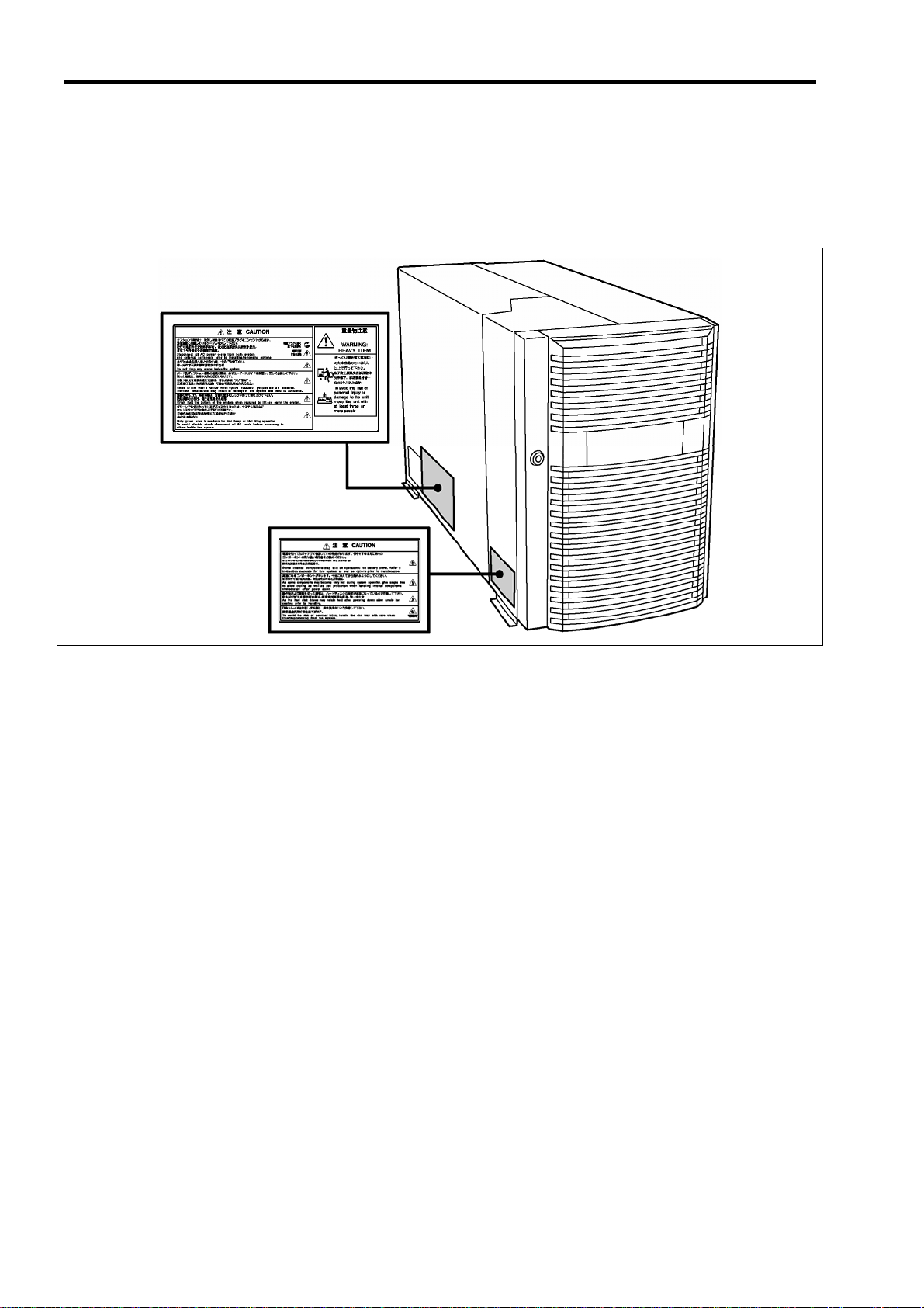
WARNING LABELS
A warning label is attached to components with possible danger or their vicinity in your server to inform the user that a
hazardous situation may arise when operating the server. (Do not intentionally remove or damage any of these labels.)
If you find any label totally/partially removed or illegible due to damage, contact your sales representative.
Page 19
1-3
SAFETY NOTES
This section provides notes on using your server safely. Read this section carefully to ensure proper and safe use of the
server. For symbols, see "SAFETY INDICATIONS" provided earlier.
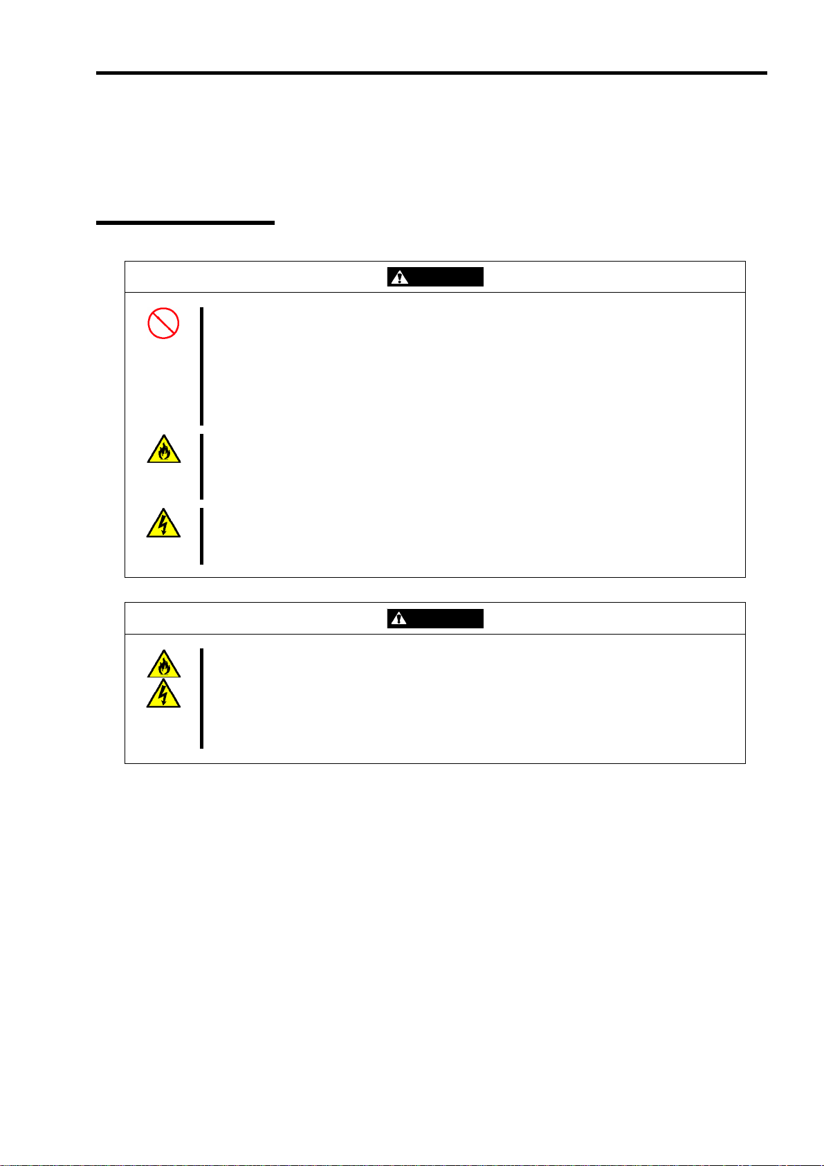
General
WARNING
Do not use the server for services where critical high availability may directly affect human lives.
Your server is not intended to be used with or control facilities or devices concerning human
lives, including medical devices, nuclear facilities and devices, aeronautics and space devices,
transportation facilities and devices; and facilities and devices requiring high reliability. We
assume no liability for any accident resulting in personal injury, death, or property damage if the
server has been used in the above conditions.
Do not use the server if any smoke, odour, or noise is present.
If smoke, odour, or noise is present, immediately turn off the POWER switch and disconnect the
power plug from the outlet, then contact your service representative. Using the server in such
conditions may cause a fire.
Keep needles or metal objects away from the server.
Do not insert needles or metal objects into ventilation holes in the server or openings in the
fl
oppy disk or CD-ROM drive. Doing so may cause an electric shock.
Keep water or foreign matter away from the server.
Do not let any form of liquid (water etc.) or foreign matter (e.g., pins or paper clips) enter the
server. Failure to follow this warning may cause an electric shock, a fire, or a failure of the
server. When such things accidentally enter the server, immediately turn off the power and
disconnect the power plug from the outlet. Do not disassemble the server. Contact your service
representative.
CAUTION
Page 20

1-4
Power Supply and Power Cord Use
WARNING
Do not hold the power plug with a wet hand.
Do not disconnect/connect the plug while your hands are wet. Failure to follow this warning may
c
ause an electric shock.
Plug in to a proper power source.
Use a proper wall outlet. Use of an improper power source may cause a fire or a power leak.
Do not install the server where you need an extension cord. Use of a power cord that does not
meet the power specifications of your server may heat up the cord and cause a fire.
Do not connect the power cord to an outlet that has an illegal number of connections.
The electric current exceeding the rated flow overheats the outlet, which may cause a fire.
Insert the power plug into the outlet as far as it goes.
Heat generation resulting from a halfway inserted power plug (imperfect contact) may cause a fire.
Heat will also be genera ted if condensation is formed on dusty blade s of the halfway inserted plug,
increasing the possibility of fire.
Use an authorized power cord only.
Use only the power cord that comes with your server. Use of an unauthorized power cord may
cause a fire when the electric current exceeds the rated flow.
Also, observe the following to prevent an electric shock or fire caused by a damaged cord.
Do not stretch the cord harness.
Do not pinch the power cord.
Do not bend the power cord.
Keep chemicals away from the power cord.
Do not twist the power cord.
Do not place any object on the power cord.
Do not bundle power cords.
Do not alter, modify, or repair the power cord.
Do not secure the power cord with staples or equivalents.
Do not use any damaged power cord. (Replace a damaged power cord with a new one of the
same specifications. Ask your service representative for replacement.)
Do not use the attached power cord for any other devices or usage.
The power cord that comes with your server is designed aiming to connect with this server and
to use with the server, and its safety has been tested. Do not use the attached power cord for
ny other purpose. Doing so may cause a fire or an electric shock. a
CAUTION
Page 21
Installation, Relocation, Storage, and Connection
1-5
CAUTION
Never attempt to lift the server only by three persons or less.
Your server weighs 75 kg (depending on its hardware configuration). Carrying the server only by
three persons or less may strain your back. Hold the server firmly by its bottom with four
persons or more to carry it. Do not hold the front door to lift the server. The front door may be
disengaged from the server, causing personal injury.
Do not install the server in any place other than specified.
Do not install the server in the following places or any place other than specified in this manual.
Failure to follow this instruction may cause a fire.
a dusty place
a humid place such as near a boiler
a place exposed to direct sunlight
an unstable place
Do not connect any interface cable with the power cord of the server plugged to a power source.
Make sure to power off the server and unplug the power cord from the power outlet before
installing/removing any optional internal device or connecting/disconnecting any interface cable
to/from the server. If the server is off-powered but its power cord is plugged to a power source,
touching an internal device, cable, or connector may cause an electric shock or a fire resulted
from a short circuit.
Do not use any unauthorized interface cable.
Use only interface cables provided by us and locate a proper device and connector before
connecting a cable. Using an authorised cable or connecting a cable to an improper destination
may cause a short circuit, resulting in a fire.
Also, observe the following notes on using and connecting an interface cable.
Do not use any damaged cable connector.
Do not step on the cable.
Do not place any object on the cable.
Do not use the server with loose cable connections.
Do not use the equipment in the place where corrosive gases exist.
Make sure not to locate or use the server in the place where corrosive gases (sulphur dioxide,
hydrogen sulphide, nitrogen dioxide, chlorine, ammonia, ozone, etc) exist.
Also, do not set it in the environment where the air (or dust) includes components accelerating
corrosion (ex. sulphur, sodium chloride) or conductive metals. There is a risk of a fire due to
corrosion and shorts of an internal printed board.
Do not provide the wiring for the server to exceed the rating of the power supply.
To prevent burns, fires, and device damages, the power supplied to the server shall not exceed
the rating load of the power branch circuit. The server requires three or four Power Cords
(depending on your configuration). Connect each power cord to each appropriate Wall Outlet
provided with 20A branch circuit. Contact your electric constructor or the local power company
for the requirements on the wiring and installation of electric facilities.
Page 22
1-6
Cleaning and Working with Internal Devices
Do not disassemble, repair, or alter the server.
Never attempt to disassemble, repair, or alter the server on any occasion other than described
in this manual. Failure to follow this instruction may cause an electric shock or fire as well as
malfunctions of the server.
Do not look into the CD-ROM drive.
A laser beam used in the CD-ROM drive is harmful to the eyes. Do not look into or insert a
mirror into the drive while the drive is powered. If a laser beam is caught in your eyes, you may
lose your eyesight (the laser beam is invisible).
Do not remove the lithium and NiMH batteries.
Your server contains lithium and NiMH batteries. Do not remove the battery. Danger of
explosion if the battery is incorrectly replaced. Placing the battery close to a fire or in the water
may cause an explosion.
When the server does not operate appropriately due to dead lithium and/or NiMH batteries,
contact your service representative to replace it only with the same or equivalent type
recommended by us. Do not disassemble the server to replace or recharge the battery by
yourself.
Disconnect all the power plugs before accessing inside the server, or connecting the
peripherals.
The server has two power cords.
Make sure to power off the server and disconnect all power plugs from the power outlets before
cleaning or installing/removing internal optional devices. T ouching any internal device of the
server with its power cords connected to a power source may cause an electric shock even of
the server is off-powered.
Disconnect all the power plugs from the outlet occasionally and clean the plug with a dry cloth.
Heat will be generated if condensation is formed on a dusty plug, which may cause a fire.
High temperature
Immediately after the server is powered off, its internal components such as hard disks are very
hot. Leave the server until its internal components fully cool down before installing/removing any
component.
Make sure to complete board installation.
Always install a board firmly. An incompletely installed board may cause a contact failure,
resulting in smoke or fire.
Protect the unused connectors with a protective cap.
The unused power supply cable connectors are covered with a protective cap to prevent short
circuits and electrical hazards. When removing the power supply cable connector from the
internal devices, attach a protective cap to the connector. Failure to follow this warning may
cause a fire or an electric shock.
Do not touch any electrical component inside the server during the hot-swap replacement.
All power flows inside the server during the hot-swap of replaceable components (PCI add-in
cards, hard disk, cooling fan, and power supply). Do not touch the electrical components inside
the server to avoid an electric shock.
WARNING
CAUTION
Page 23
During Operation
1-7
Avoid contact with the server during thunderstorms.
Disconnect all power plugs from the outlets when a thunderstorm is approaching. If it starts
thundering before you disconnect the all power plugs, do not touch any part of the server
including the cables. Failure to follow this warning may cause a fire or an electric shock.
Keep animals away from the server.
Failure to follow this warning may cause a fire or an electric shock.
Do not place any object on top of the server.
An object placed on top of the server may fall down, resulting in damage to your property
around the server.
Do not use a cellular phone or pager around the server.
Turn off the cellular phone or pager. Radio interference may cause malfunctions of the server.
Do not remove the cooling fans.
Only an authorized service technician can remove the cooling fans from the server.
CAUTION
Page 24

1-8
FOR PROPER OPERATION
Observe the following notes for successful operation of the server. Use of the server ignoring these notes will cause
malfunctions or failures of the server.
Install the server in a place that meets requirements for successful operation. For details, see Chapter 3,
"Setting Up Your Server."
Do not delete the hard disk partition exclusively provided for maintenance of the server although it may
appear on the operating system.
Make sure to power off the server before connecting or disconnecting cables between the server and
peripheral devices.
Verify that the access lamp on the server is unlit before turning off the server or ejecting the floppy disk.
The server management logic on your system board monitors and logs system voltage changes. When
plugging the power cord to the system, you may experience 10 seconds delay from the time you press the
POWER switch on the front panel. This is normal system operation and is required by the server management
logic.
When you have just turned off the server, wait at least 30 seconds before turning it back on.
Do not turn off the server until characters following our logo appear on the screen.
Turn off the power and unplug the power cord from the outlet before relocating the server.
Some software includes a command to eject the CD-ROM tray. Make sure that the front door is opened before
running the command. Running this command with the front door clos ed may cause the CD-ROM tray or the
media to hit against the front door, resulting in a failure of the server.
Clean the server on a regular basis. (See Chapter 7 for cleaning.) Regular cleaning proactively prevents
various failures of the server.
Lightning may cause a momentary voltage drop. To prevent this problem, it is recommended to use an
uninterruptible power supply unit.
Check and adjust the system clock before the operation if any of the following conditions is applicable.
– After transport of the server
– After storage of the server
– After the server is entered into the paus e state under the environmental condition enduring the server
operation (temperature: 10°C to 35°C, humidity: 20% to 80%)
Check the system clock at the rough rate of once per month. When the system clock is installed in a system
requiring high time precision, it is recommended to use a time server (NTP server).
If the system clock is remarkably delayed or advanced as the passage of time in spite of adjustment, contact
your service representative to ask for maintenance.
Store the unit under the storage condition (temperature: -10°C to 55°C, humidity: 20% to 80%, without
condensation) to allow built-in devices and the unit to operate correctly in the next operation.
Make sure to use optional devices supported by the server. Some non-supported devices may be physically
installed/connected but cause failures of the server as well as malfunctions of the server.
We recommend you use our genuine products. Some third-party products claim that they suppo rt the server.
However, repair of the server due to a failure or damage resulting from use of such third-party products will
be charged.
Playback of disks that do not conform to CD-ROM standards with the CD-ROM drive is not guaranteed.
Page 25

TRANSFER TO THIRD PARTY
The following must be observed when you transfer (or sell) the server or software provided with the server to a third
party:
Express server
Make sure to provide this manual along with the server to a third party.
IMPORTANT: About data on the hard disk
Be sure to take appropriate measures not to leak important data (e.g., customers'
information or companies' management information) on the removed hard disk to any third
parties.
Data seems to be erased when you empty "Recycle Bin" of Windows or execute the
"format" command of the operating system. However, the actual data remains written on
the hard disk. Data not erased completely may be restored by special software and used for
unexpected purposes.
It is strongly recommended that the software or service (both available at stores) for data
erasure should be used in order to avoid the trouble explained above. For details on data
erasure, ask your sales representative.
1-9
Provided software
To transfer or sell any software application that comes with the server to a third party, the following requirements must
be satisfied:
All provided software applications must be transferr e d and no backup copies must be retained.
Transfer requirements listed in "Software License Agreement" that comes with each software application must
be satisfied.
Software applications that are not approved for transfer must be uninstalled before transferring the server.
Page 26
1-10
CONSUMABLES
Your server contains some components that are only good for a limited period of time and require replacement, such as
batteries, fans, the internal CD-ROM drive, the floppy disk drive, and the mouse. For stable operation of the server, we
recommend you replace these components on a regular basis. Contact your service representative for replacement or the
product.
DISPOSAL OF THE SERVER
Dispose of the server, all the internal devices, floppy disks, and CD-ROMs according to all national laws and
regulations. Also dispose of the power cord provided with the server to avoid diversion to some other devices.
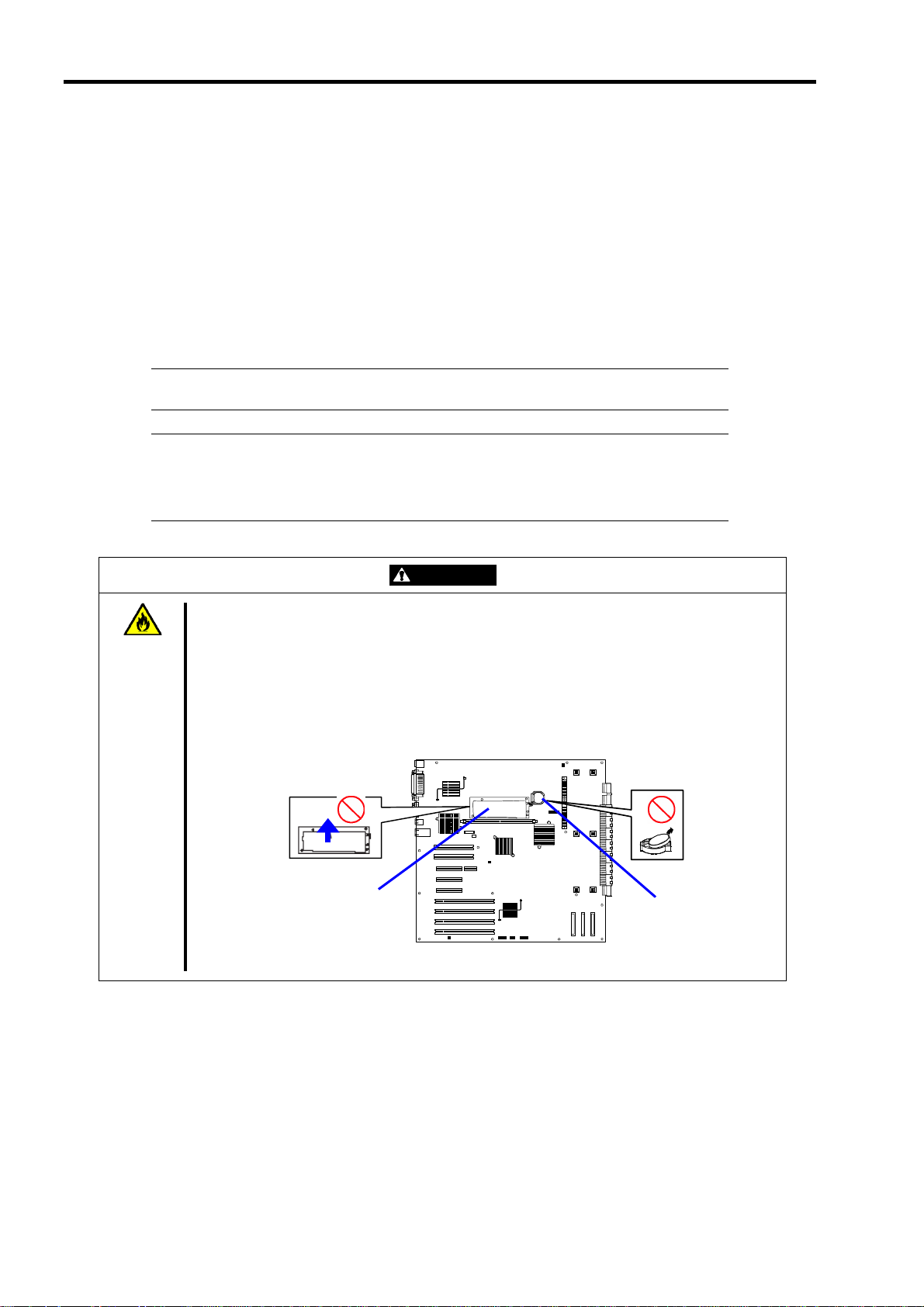
IMPORTANT: For disposal (or replacement) of the battery on the IO board of the server,
contact your service representative.
NOTE: If the real-time clock battery on the I/O board reaches its life, the following
message appears on the display while running the POST. Contact your service
representative to replace the battery.
0250 System battery is dead –Replace and run SETUP
When the server does not operate appropriately due to the failure of lithium and/or NiMH
WARNING
Do not remove the lithium and NiMH batteries.
Your server contains lithium or NiMH batteries. Do not remove any battery. Danger of explosion
if the battery is incorrectly replaced. Placing the lithium or NiMH battery close to a fire or in the
water may cause an explosion.
batteries, contact your service representative to replace it only with the same or equivalent t ype
recommended by us. Do not disassemble the server to replace or recharge the battery by
yourself.
NiMH battery
Lithium battery
IO board
Page 27

1-11
USER SUPPORT
When the server needs after-sales service, check if the warranty is still valid, and determine which service is necessary
as indicated on the "Certificate".
Before asking for repair, do the following when the server appears to fail:
1. Check if the power cord and the cables to other devices are properly connected.
2. See Chapter 8 to find if your problem fits the description. If it does, take the recommended measure for it.
3. Check if the software required for operation of the server is properly installed.
4. Check the server using a computer virus detection program. Computer virus detection programs are available
for purchase in stores.
If the server still appears to fail after you have taken the above actions, contact your service representative immediately.
Take notes on lamp indications of the server and alarm indications on the display unit before, it may provide a
significant help to your service representative.
When Having Your Server Repaired
Prepare the following when having your server repaired:
Certificate
Notes of the messages displayed on the display unit
Error information*
Records of the Express server and peripheral equipment
* Error information includes the Error Message shown in Chapter 8.
Prepare the error information only when required by your service representative.
Page 28
1-12
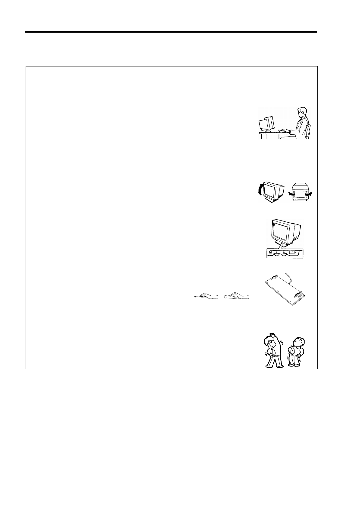
Setting Up a Healthy Work Environment
The longer you keep using the computer equipment, the more you become tired, which may
cause disorders of your body. When you use a computer, observe the following to keep
yourself from getting tired:
Good Working Posture
You have good posture if the following are satisfied when you use a computer:
• You sit on a chair with your back straight.
• Your hands are parallel with the floor when you put them on the keyboard.
• You look at the screen slightly lower than your eye height.
You have "good working posture" as described in the above when no part of your body is
under excess strain, in other words when your muscles are most relaxed.
You have "bad posture" when you sit with your back hunched up or you operate a display
unit with your face close to the screen. Bad working posture may cause eye strain or poor
eyesight.
Display Unit Angles Adjustment
Most display units are designed for adjustment of the horizontal and vertical angles. This
adjustment is important to prevent the screen from reflecting bright lights and to make the
display contents easy to see. You will not be able to keep "good working posture" and you
will feel more tired than you should if you operate a display unit without adjusting horizontal
and vertical angles.
Screen Brightness and Contrast Adjustment
The display unit has brightness and contrast adjustment functions. The most suitable
brightness and contrast depend on the individual and the working environment (well-lighted
room or insufficient light). Adjust brightness and contrast so that the screen will be easy to
see. An extremely bright or dark screen will give a bad effect to your eyes.
Keyboard slope Adjustment
The keyboard provided with the server is designed for slope adjustment. Adjust the
keyboard angle at which the keyboard is easy to operate. The adjustment assists in
reducing strain on your shoulders, arms, and fingers.
Equipment Cleaning
Clean equipment regularly. It is difficult to see the display contents on a dusty screen.
Keeping equipment clean is also important for your sight.
Fatigue and Rest
If you feel tired, you should stop working and do light exercises.
Page 29

Chapter 2
General Description
This chapter provides information that you should be familiar with before using the server. It includes names and
functions of the components and features of the server.
Page 30
2-2
OVERVIEW
You r serv er is a high ly reliable, high-powered, fault-tolerant, high-capacity, multiprocessing server based on the 64-bit
Intel® Xeon™ Processor MP. It is a solid performer and offers the latest technology. The combination of computing
performance, memory capacity, and integrated I/O provides a high performance environment for many server market
applications. These range from large corporations supporting remote offices to small companies looking to obtain basic
connectivity capability such as file and print services, e-mail, web access, web site server, etc.
Your server includes a 3.5-inch diskette drive, a CD-ROM drive, a 3.5-inch hard disk bay, and removable media device
bay. In the basic configuration, the 3.5-inch hard disk bay supports up to five 1.0-inch height SCSI hard disk drives that
can be swapped in or out of the system without powering it down, if RAID functionality is configured in the system. If
the additional hard disk drive cage is installed in your server, the 3.5-inch hard disk bay supports up to thirteen 1.0-inch
height SCSI hard disk drives.
As application requirements increase, you can expand your server with an additional processor, additional memory,
add-in boards and peripheral devices: tape devices, CD-ROM, and hard disk drives.
Page 31

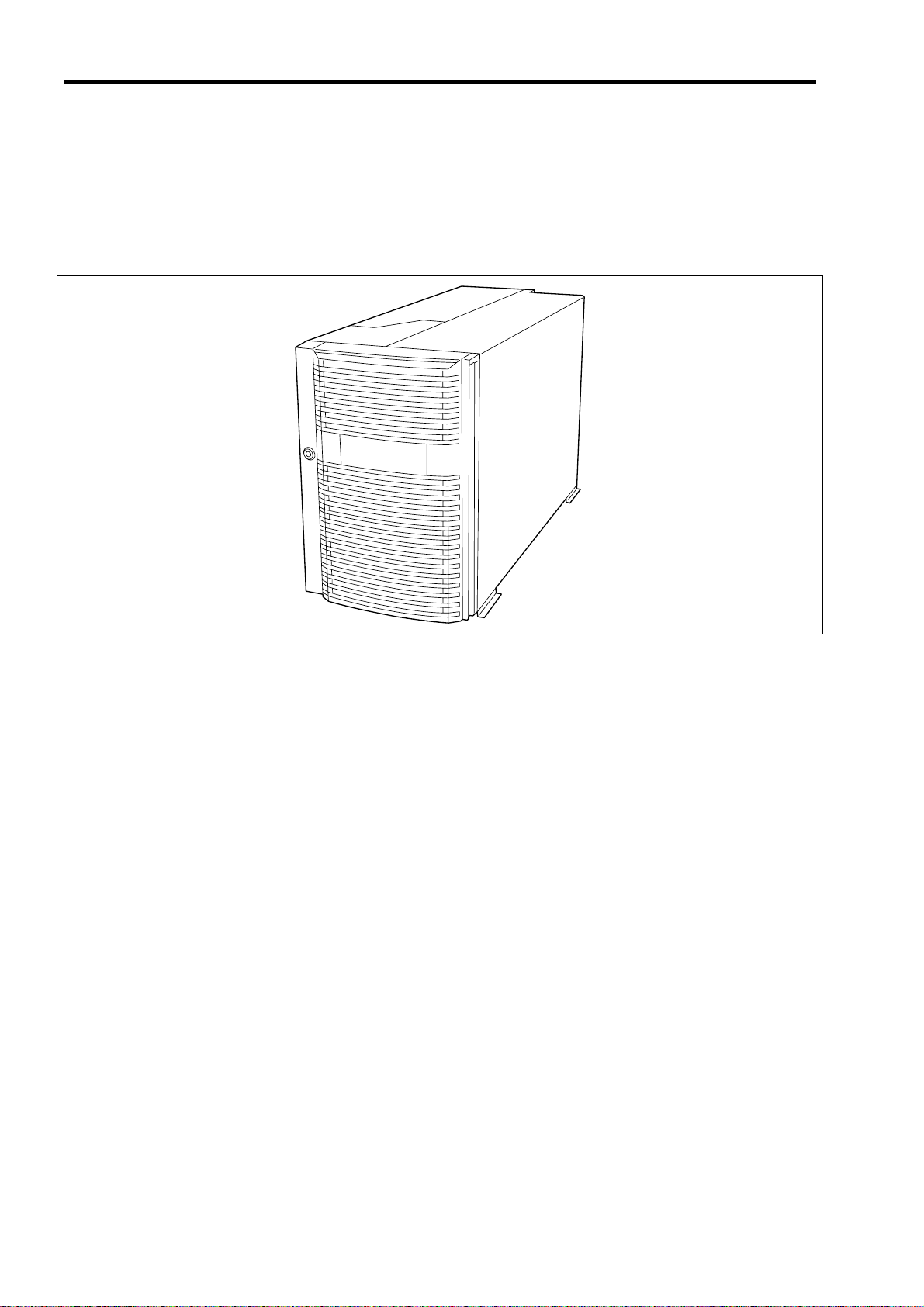
External View
2-3
1
3
4
2
1 Front door
Open the front door when you access to the POWER switch, the 5.25-inch device, the CD-ROM drive, or the
optional USB floppy disk drive or install or remove a hard disk drive, processor, memory board, and/or the DIMM.
2 Key slot
Insert the security key to lock or unlock the front door.
3 Rear access cover
Open the rear access cover to install or remove the PCI boards and fans.
4 Stabilizer (2 each side at front and rear)
Remove the stabilizers when converting the server to rack-mounting model.
Page 32

2-4
Front View (with the Front Door Open)
1-1
1-2
1-3
See "Lamps" described later.
1
2 3
5
8
7-3
2-1
7-4
2-2
4
3-0
2-3
4
3-1
7-2
6-5
6-4
3-2
6-3
6-2
6-1
4
1 3.5-inch floppy disk drive
Insert a 3.5-inch floppy disk to the 3.5-inch floppy disk drive to read data from the disk or write data to the disk.
1-1: Eject button 1-2: Disk slot
1-3: Floppy disk access lamp (lits green when accessing)
2 CD-ROM drive
The CD-ROM drive reads data from the inserted CD-ROM.
2-1: Emergency eject hole - 2-2: CD Tray eject button - 2-3: Access lamp lits orange when accessing)
3.5-inch disk bay
3
The 3.5-inch hard disk bay contains additional hard disk slots. Hard disk drives having the thickness of 1 inch can
be inserted into the slots. The number following the bold-faced character indicates the SCSI ID.
4 DISK lamp
5 Processor board
5-1: Processor board ejector
6 Memory board
6-1: Memory board ejector - 6-2: Memory board power lamp - 6-3: Memory board attention lamp
6-4: Memory board redundancy lamp - 6-5: Memory board attention switch
7 Additional memory board slot
The number following the bold-faced character indicates the slot number.
Additional memory board shall be installed in the slot #2, #3, and then #4 in this order.
8 5.25-inch device bay
DAT (digital audio tape) drive or optical disk drive may be installed in the 5.25-inch device bays. Slot #1 (right)
and slot #2 (left).
9 Additional 3.5-inch disk bay
Install the optional HotSwap HDD cage 3-drive SCSI Media Bay in this bay. With the cage, up to thirteen hard
disk drives can be connected to the server.
3-3 3-4 5-1
6
Page 33

Front View (Switch and LED Panel)
2-5
1
2 3 4
5 to 10 from left
18
19
1 POWER switch
The power switch is used to turn on/off the power. If you press the switch once, then the POWER/SLEEP lamp
goes on and the power is turned on. If you press the switch again, the power is turned off. The system is forcibly
shut down when the power switch is pressed continuously for four seconds or longer.
2 RESET switch
The reset switch is used to reset the server.
3 SLEEP switch
If you press the sleep switch once, the server enters into the sleep state (power saving mode). If you press the
switch again, the server recovers to the normal state. Windows Server 2003/Windows 2000 support this feature.
4 UID (Unit ID) switch
Pressing the UID switch turns UID lamp (blue) located on the front panel and the rear panel on and off.
5 POWER/SLEEP lamp
6 STATUS lamp
7 DISK ACCESS lamp
8 LAN1 access lamp
9 LAN2 access lamp
10 UID (Unit ID lamp)
11 DUMP lamp
12 Processor board error lamp
13 Memory board error lamp
14 I/O board error lamp
15 Power unit error lamp
16 Fan error lamp
17 Thermal error lamp
18 DUMP switch
The dump switch is used to collect the event logs having occurred in the server.
19 CLEAR switch
11 to 17 from left
Page 34

2-6
Rear View
14
15
17
16-2
18
9
13-2
13-1
10
11
12
21
20
19
7 8
16-1
18
1-4 1-3 1-2 1-1
17
2
3-4
3-3
3-2
6 5 4
3-1
Page 35

1 Power supply unit
The power supply unit supplies DC powers to the server. The factory-installed power supply units are installed in
slots 1 and 2 and slots 3 and 4 are for optional power supply units for power redundant configuration.
2 AC inlet
The AC inlet is connected with the power cord. Each power supply unit has one socket. Use the provided power
cord.
3 Additional PCI board slot
3-1: 64bit/100MHz, hot-plug PCI-X
3-2: Hot-plug PCI-Express (x8)
3-3: Non-hot-plug PCI-Express (x4)
3-4: 32-bit/33MHz, non-hot-plug PCI
4 PCI slot Fault lamp
5 PCI slot POWER lamp
6 PCI slot error lamp
7 Mouse connector
Used to connect the optional mouse.
8 Keyboard connector
Used to connect the optional keyboard.
9 Printer port connector
Used to connect a printer with Centronics interface.
10 Serial port A connector
Serial port A connector is used to connect the server to a device with serial interface. The server cannot be
directly connected to a leased line through this connector.
11 Serial port B connector
To be used exclusively with the serial port B connector on the front panel.
12 Management LAN Port
13 ICMB connector
Used to connect a device having ICMB interface. The number following the bold-faced character shows the port
number.
14 Monitor connector
Used to connect the display unit.
15 USB connector
Used to connect a device with USB interface.
16 LAN connector
Used to connect a network system on LAN.
The number following the bold-faced character shows the port number.
17 LINK/ACT lamp
18 1000/100/10 lamp
19 BMC error lamp
20 Processor board error lamp
21 I/O board error lamp
2-7
Page 36

2-8
Internal View
3
1
2
4
1 Power supply cage
2 Non-hot-plug PCI slot
3 Hot-plug PCI slot
4 Fan bay
Page 37

I/O Board
2-9
17 16 15 14 12
1
2
13
3 4 5 7 8
1 Connectors for external devices
2 PCI slot error lamp (corresponds to PCI slots #1 to #9 from top)
3 PCI slot power lamp (upper) / PCI slot Fault lamp (lower)
(corresponds to PCI slots #4 to #9 from top)
4 PCI board slot (PCI slots #1 to #9 from top)
Slots 1, 2: Non-hot-plug PCI, 5V, 33MHz
Slot 3: Non-hot-plug PCI-Express (x4)
5 IPMB connector
6 BMC configuration jumper block
7 Jumper switch for CMOS/Password clear
8 Management LAN board connector
9 Fan connector
Number following the bold-faced number indicates port number.
10 SCSI connector
Ch-2, Ch-1, and HDD cage from left
11 Fan error lamp
Number following the bold-faced number indicates fan number.
12 Power BP connector
13 Lithium battery
14 DIMM connector for RAID
15 NiMH battery module for RAID
16 Battery module connector
17 LAN controller
6
Slots 4 and 5: (Hot-plug PCI-Express (x8)
Slots 6 to 9: Hot-plug PCI-X, 3.3V, 100MHz
9-4
9-1
9-6 9-3
11-6
11-3
11-2
9-2
9-5
11-5
11-4
11-1
10
Page 38

2-10
Processor Board
1-1 1-2 1-4 1-3
2-1
3-1 3-2 2-2
2-4
3-4 3-3 2-3
1 VRM (Number following the b old-faced character indicates the socket number.)
2 Processor (Nu m ber following the bold-faced character indicates the socket number.)
3 Processor/VRM error lamp
(Number following the bold-faced character indicates the lamp number.)
Page 39

Memory Board
2-11
5 6
7-4
8
7-3
7-2
7-1
1 DIMM slot error lamp (DIMM slot #1 to 4 from bottom)
2 Memory board Eject switch
3 Memory board Power lamp
4 Memory board Attention lamp
5 Memory board Redundancy lamp
6 Memory board Attention switch
7 DIMM slot (Number following the bold-faced character indicates the socket number.)
The factory-installed memory board contains at least 2 x 512MB DIMM in slots 1 and
2.
8 Switch to turn on DIMM slot error lamp
1 2 3
4
Management LAN Board
1
2
3
1 ICMB #1 connector
2 ICMB #2 connector
3 Management LAN Port
4 I/O board connector
4
Page 40

2-12
STANDARD FEATURES
High performance Expandability
64-bit Intel® Xeon™ Processor MP
3.16GHz/1MB
3.66GHz/1MB
3.33GHz/8MB (on specific configurations
only)
High-speed memory access
(Supports DDRII 400-compliant
interleaved memory)
High-speed 1000BASE-T/
100BASE-TX/10BASE-T interface
(1000Mbps/100Mbps/10Mbps
supported)
High-speed disk access
(Ultra320 SCSI x 2)
Many Available Features
Graphic accelerator "Radeon7000M" support
El Torito Bootable CD-ROM (no emulation mode) format support
POWER switch mask
Software power-off
Remote power-on feature
AC-LINK feature
Intelligent Platform Management Interface (IPMI) feature
High-reliability Self-diagnosis
Online sparing memory feature
Memory hot-swap feature
MemoryRAID feature
Memory monitoring feature (single-bit error
correction/ double-bit error detection)
Memory/processor degradation feature
(logical isolation of a failed device)
Bus parity error detection
Thermal sensor
Error notification
Internal cooling fan monitoring feature
Internal voltage monitoring feature
BIOS password feature
Security feature (security lock)
Redundant power supply
Disk array (onboard)
Recovering BIOS Data
Management Utilities
ESMPRO
DianaScope
Advanced Remote Management
Baseboard Management Controller (BMC)
Remote console feature
Wide variety of optional I/O slots
Two 32-bit/33 MHz PCI slots
Four 64-bit/100 MHz PCI-X sots (support hot-plug)
Two PCI EXPRESS(x8) slots (support hot-plug),
One PCI EXPRESS(x4) slot.
Large memory of up to 32 GB
3.5-inch hard disk drive bay holds five hot-swap SCSI hard
disk drives. If additional hard disk drive cage is installed,
system can support up to 13 hot-swap SCSI hard disk drives.
Remote power-on feature
Up to four multi-processors are available for upgrade.
USB interface
Power On Self-Test (POST) Memory mirroring feature
Test and Diagnosis (T&D)
Maintenance Features
Off-line Maintenance Utility
Memory dump feature using the DUMP switch
Power Saving Feature
Sleep feature (available for Windows Server
2003/Windows 2000)
Easy and Fine Setup
EXPRESSBUILDER (system setup utility)
Express Setup
Configuration Diskette Creator
SETUP (BIOS setup utility)
SCSI Configuration Utility (SCSI device utility)
Page 41

2-13
Power Supplies
When the additional power supply units are installed and system operates with four power supply units, the server can
continue its operation without interruption even if one of these power supply units fails (in the redundant configuration).
If an additional power supply unit is installed while the system is operating with three power supply units, a log that
represents "power recovery" is recorded in the system event log. This indicates that the power supply is in redundant
configuration and maximum configuration.
Peripheral Bays
The system supports a variety of standard PC AT-compatible peripheral devices. The chassis includes the following
peripheral bays:
Media bay for installing the standard 3.5-inch floppy disk drive (supports 720 KB and 1.44 MB floppy di sk
media) and the standard CD-ROM drive.
A 5.25-inch device bay for installing up to two half-height 5.25-inch peripheral devices or a full-height
5.25-inch peripheral device such as an optional tape drive.
The SCSI hard disk drive bay for installing up to five SCSI hard disk drives. If you install the additional hard
disk drive cage, you can install up to thirteen SCSI hard disk drives.
The SCSI disk drives can be easily installed or removed. The drive carrier allows you to access to disk drives
from the front of the system. If disk drives are provided with RAID configuration within the system, a disk
drive can be swapped with another without power interruption in the system (hot-swap).
NOTE: The SCSI hard disk drive bays cont ain a hot -swap back plane that requires an
80-pin single connector attachment (SCA) connector on the drives that you install.
Page 42

2-14
Memory Mirroring / Memory RAID Feature
Memory Mirroring Feature
The memory mirroring feature places a memory board as spare memory in standby state. If the current memory board
encounters an uncorrectable error, the memory mirroring feature switches to the standby memory board. When this
feature is used, the current memory board and the standby memory board should be combined. Available combinations
are:
Mirroring with memory boards 1 and 2
Mirroring with a pair of memory boards 1 and 2 and a pair of memory boards 3 and 4
To enable the memory mirroring feature, the combined memory boards must have DIMMs of same capacity.
The table below shows combinations of memory boards installed.
Memory board 1 Memory board 2 Memory board 3 Memory board 4
A 2GB (1GB*2) 2GB (1GB*2) 2GB (1GB*2) 2GB (1GB*2)
B 8GB (2GB*4) 8GB (2GB*4) 8GB (2GB*4) 8GB (2GB*4)
C 4GB (1GB*4) 4GB (1GB*4) – –
Memory RAID Feature
If one of the four memory boards encounters an uncorrectable error, the memory RAID feature switches to the other
memory board to continue operation. To use this feature, four memory boards must be installed. Each memory board
must have DIMMs of same capacity.
The table below shows combinations of memory boards installed.
Memory board 1 Memory board 2 Memory board 3 Memory board 4
A 2GB (1GB*2) 2GB (1GB*2) 2GB (1GB*2) 2GB (1GB*2)
B 8GB (2GB*4) 8GB (2GB*4) 8GB (2GB*4) 8GB (2GB*4)
C 4GB (1GB*4) 4GB (1GB*4) 4GB (1GB*4) 4GB (1GB*4)
Setting BIOS
Start SETUP and select [Advanced] → [Memory Configuration] → [Memory RAS Feature] in order and set as follows:
To enable the memory mirroring feature: Select [Mirror].
To enable the memory RAID feature: Select [RAID].
Others
Memory capacity displayed on the operating system = total capacity of physically install ed memory –
capacity for standby memory
Memory mirroring feature: 1/2 of actually installed memory capacity
Memory RAID feature: 3/4 of actually installed memory capacity
Enabling the memory mirroring or memory RAID feature does not influence the operations of applications.
Each feature is automatically disabled when an error message is displayed:
The following indicates that the memory mirroring /memory RAID feature has worked:
a) The Redundancy lamp on the front panel of the server lights green.
b) The failing DIMM group is degraded when the server restarts.
c) If an ESMPRO Agent has been installed, the following log is registered as a system log of Event Viewer:
Source name: ESMCommonService
Event ID: 2313
Explanation: Part of the DIMM was isolated due to a memory error.
Page 43

2-15
Memory number: XX
Date/time: XX
d) If report setting is made through the ESMPRO Agent, Manager reporting and ALIVE reporting is
performed. The report contents are as follows:
Explanation: Part of the DIMM was isolated due to a memory error.
Memory number: XX
Date/time: XX
Recovering BIOS Data
Two system BIOSes, primary and secondary, are used to realize the duplex configuration.
Normally, the system operates with the primary BIOS. If a primary BIOS data error occurs or if the device containing
the system BIOS fails, control is immediately transferred to the secondary BIOS. Thus, the activation of the system is
ensured.
At shipment, the latest version of system BIOS is stored both in the primary and the secondary BIOS. If you execute the
system BIOS update, the secondary BIOS is updated, and the updated BIOS becomes the primary BIOS. Thereafter, the
system is activated from that primary BIOS.
SAF-TE Logic
The SCSI backplane includes SAF-TE (SCSI Accessed Fault Tolerant Enclosure) logic that provides an interface to the
disk subsystem that supports status signals, hot swapping drives, and enclosure monitoring.
The transport mechanism for the standardized alert detection and status reporting is the SCSI bus. Disk drives, power
supplies, cooling fans, and temperature are continually monitored and the conditions then reported over the SCSI bus to
the system. When used with RAID management software the user can be alerted of impending or imminent disk
conditions requiring attention. This allows the user to react to conditions that could normally go unnoticed until data
loss.
System Cooling
The chassis includes a hot-swappable fan module with six fans for cooling the processor(s), hard drives, and PCI cards.
The fan system is located in the middle of the chassis to pull cooling air through the chassis.
Page 44

2-16
System Board Features
The following subsections describe the system board major components.
Processor
The processor board accommodates one to four 64-bit Intel® Xeon™ MP processors with 1 MB cache in an FC-PGA2
package.
DIMM Memory
To install or replace a DIMM, remove the memory board first.
One memory board is factory-installed in the server. Up to four memory boards (32 GB maximum) can be installed in
the server.
Install the DIMM (Dual Inline Memory Module) into the DIMM socket on the memory board of the server. DIMMs are
installed in the ascending order of DIMM socket numbers in the unit of two modules.
The controller automatically detects, sizes, and initializes the memory array, depending on the type, size, and speed of
the installed DIMMs, and reports memory size and allocation to the server via configuration registers.
NOTE: Use DIMMs that have been provided by us. Contact your service representative or
dealer for a current list of approved memory modules.
Onboard Video
The I/O board incorporates an ATI® Radeon® 7000M graphics accelerator with 16 MB of video SDRAM that supports
all standard IBM VGA modes. The embedded SVGA video subsystem supports:
Pixel resolutions up to 1024 × 768
CRT and LCD monitors up to 100 Hz vertical refresh rate
The I/O board supports disabling of the onboard video through BIOS Setup or when a plug-in video card is installed in
any of the PCI slots.
On Board RAID Controller
The I/O board includes an on-board RAID c ontroller, which is composed of NQ 80 3 32 I/ O pr ocessor and 53C1030 SCSI
host adapter. The on-board RAID controller supports the following features:
Dual-channel Ultra320 SCSI interface (CH0 and CH1)
Connect the HDD cage to CH0, and HDD cage or tape device to CH1.
RAID levels 0, 1, 5, and spanning of RAID1 and RAID5
256 MB of cache memory
Battery-backup cache memory
Page 45

2-17
Network Interface Controllers
NOTE: To ensure EMC product regulation compliance, the system must be used with
shielded LAN cables.
The I/O board includes Intel® 82546GB network interface controller (NIC). The Intel® 82546GB network interface
controller supports the following features:
Two channels of 10Base-T, 100Base-TX, and 1000BASE-T networks.
Direct 64-bit, 133 MHz interface to the PCI-X bus
82546GB provides standard IEEE 802.3 Ethernet Interface for 1000Base-T, 100Base-TX, and 10Base-T
(802.3, 802.3u, 802.3ab).
System Board Management Controller (BMC)
Server management is concentrated in the System Board Management Controller (BMC). The BMC and associated
circuitry are powered from a 5Vdc standby voltage, which remains active when system power is switched off, but the
AC power source is still on and connected.
The BMC supports DianaScope, which allows remote server management through networks.
See Chapter 6 or online document in the EXPRESSBUILDER CD-ROM for DianaScope.
One major function of the BMC is to autonomously monitor system management events, and log their occurrence in the
non-volatile System Event Log (SEL). The events being monitored include overheating and overvoltag e conditions, fan
failure, or chassis intrusion. To enable accurate monitoring, the BMC maintains the non-volatile Sensor Data Record
(SDR), from which sensor information can be retrieved. The BMC provides an ISA host interface to SDR sensor
information, so that software running on the server can poll and retrieve the server's current status.
The BMC performs the following:
Monitors server board temperature and voltage
Monitors processor presence and controls Fault Resilient Boot (FRB)
Detects and indicates fan failure
Manages the SEL interface
Manages the SDR Repository interface
Monitors the SDR/SEL timestamp clock
Monitors the system management watchdog timer
Monitors the periodic SMI timer
Monitors the event receiver
Controls secure mode, including vide o bl an ki n g, di skette write-protect monitoring, and front pa nel
lock/unlock initiation
Controls Wake On LAN via Magic Packet support.
Degradation Feature
The degradation feature automatically isolates a failed DIMM, processor, or cooling fan to assure continuous operation
of the server when the POST (Power On Self-Test, self-diagnosis program after power on) detects such a DIMM,
processor, or cooling fan.
Failed DIMMs, processors, and cooling fans may be identified on the screen that the POST displays, or with the BIOS
setup utility, "SETUP." They may also be identified on the system that has ESMPRO installed.
Page 46

2-18
Remote Power-On Feature (Wake On LAN/PME)
The remote power-on function turns on the server through a network. It sends a special packet from the management
computer to a remote server to turn it on if the server is off-powered.
To enable this feature, you must select "Enabled" for "Wake On LAN/PME" in the Advanced Chipset Control of the
Advanced menu of the BIOS setup utility, "SETUP." (See Chapter 4.)
The remote power-on feature is not available in the following cases. Press the POWER switch once to start the
operating system, and turn off the server in an appropriate procedure.
Abnormal previous system shut-down
No power supply to the server (due to turned-off breaker, disconnected power cord, power blackout, etc.)
NOTE: Wake On LAN feature is supported in 100BASE-TX/1000BASE-T adapter on the
I/O board.
AC-LINK Feature
When the power cord o f the server is connected to an uninterruptible power supply (UPS) unit, the server supports the
power linkage feature that enables control over the power supply from the UPS to the server. AC-LINK feature can be
enabled or disabled with "AC-LINK" in the Server menu of the BIOS setup utility, "SETUP." (See Chapter 4.)
Security
To help prevent unauthorized entry or use of the system, the system includes a full lockable front door and Server
Management software that monitors the system intrusion switches.
Security with Mechanical Locks and Monitoring
The front door of the server contains a mechanical lock to prevent access to the front of the computer chassis.
The server includes an intrusion switch for the rear access cover. When this cover is opened, the switch transmits an
alarm signal to the system board, where server management software processes the signal.
Software Locks via the System Setup Utility
The BIOS SETUP Utility provides a number of security features to prevent unauthorized or accidental access to the
system. Once the security measures are enabled, access to the system is allowed only after the user enters the correct
password(s). For example:
Enable the keyboard lockout timer so that the server requires a password to reactivate the keyboard and
mouse after a specified time-out period – 2 to 120 minutes.
Set and enable an administrative password.
Set and enable a user password
Set secure mode to prevent keyboard or mouse input and to prevent use of the front panel reset, power and
sleep switches.
Activate a hot-key combination to enter secure mode quickly.
Disable writing to the floppy disk drive when secure mode is set.
Page 47

2-19
EXPRESSBUILDER
The CD-ROM that comes with your server contains a setup utility called " EXPRESSBUILDER." When you have first
installed the server or append features to the server, use the EXPRESSBUILDER to set up your server.
Refer to Chapter 6 for details.
The major functions of the EXPRESSBUILDER are:
To install the Operating System.
"Express Setup" helps you to install Windows system. (See Chapter 5)
To diagnose the system.
EXPRESSBUILDER includes the System Diagnostics to check your server. (See Chapter 6)
To create a support disk.
Use this function to create the support disks used to boot the utilities from the floppy disk, or the OEM floppy
disk used for a manual installation of Windows. (See Chapter 6)
To update the BIOS.
Use this function to update the system BIOS or firmware of the server. (See Chapter 6)
To update the Windows System*
"Update Express5800 System" in Master Control Menu (Windows-based EXPRESSBUILDER feature)
updates several resources of Microsoft® Windows Server™ 2003 or Microsoft® Windows® 2000. (See
Chapter 6)
To install the utilities.
EXPRESSBUILDER CD-ROM includes some management software for Windows ( ESMPRO, DianaScope,
etc.) and maintenance utilities for DOS (System diagnostics, Off-line Maintenance Utility, etc.).
You can install the applications for Windows from Master Control Menu and install the utilities for DOS from
Tools menu. (See Chapter 6)
To read the online documents*
You can refer to the online documents from Master Control Menu. (See Chapter 6)
NOTE: Some features among those listed above can be used from the remote computer
via cross cable, modem, or LAN (remote console). See Chapter 6 for details.
* These functions are available under Windows system.
Page 48

2-20
ESMPRO
ESMPRO is a server management software application that runs on the operating system. ESMPRO includes
ESMPRO Manager for the server monitoring terminal and ESMPRO Agent for the server.
NOTE: For details of major functions of ESMPRO, system configuration and setups with
ESMPRO, see Chapter 6.
Available functions of ESMPRO depend on the oper ating system you install. Ask your
service representative for details.
Off-line Maintenance Utility
The Off-line Maintenance Utility is used for proactive maintenance and fault analysis of the server. Normally this utility
is used by the maintenance engineer.
Refer to Chapter 8 for details.
System Diagnostic Utility
The system diagnostic utility contained in EXPRESSBUILDER is useful to prevent hardware failures. See Chapter 7
for details.
DianaScope
DianaScope is a software application for remote management of the Express5800 series.
DianaScope can control the managed server even if operating system is not running on the managed server.
See Chapter 6 and online documentation in the EXPRESSBUILDER.
Page 49

2-21
USING YOUR SERVER
This section describes basic operations of your server including how to use devices such as floppy disk drive and
CD-ROM drive. See Appendix B for notes on using the floppy disk, CD-ROM, and accessories including keyboard and
mouse.
Security Lock (Locking the Front Cover)
The security lock on the front of the server is used to lock the front door.
Open the front door when turning on/off the server, accessing the floppy disk drive, CD-ROM drive, and/or 5.25-inch
device, and installing/removing the hard disk drive into/from the 3.5-inch disk bay.
IMPORTANT:
Use the security key coming with the server to release the security lock.
Some software applications have a command to eject a media in the CD-ROM drive or
5.25-inch device bay. Make sure that the front door is open before executing such a
command. If the command is executed while the front door is closed, the tray of the
CD-ROM drive or a media in the 5.25-inch device will strike the front door causing the
server failure.
Lock the front door Unlock the front door.
Unlock the front door, hold the handle half height on the left side of the front door and pull it toward you to open. When
you close the front door, lock it with security key.
Page 50

2-22
POWER Switch
Use the POWER switch to turn on/off the server.
Power On
Press the POWER switch on the front of the computer chassis.
The POWER/SLEEP lamp lights green.
POWER/SLEEP lamp
IMPORTANT:
If the power cord is connected to a power control device such as a UPS (Uninterruptible
Power Supply), make sure that the power control device is powered.
If the power cord is connected to the server, an initial diagnosis of the hardware starts.
The POWER switch does not work while in diagno si s. Wai t for ab out 3 0 s econ ds , the n
press the POWER switch.
Do not turn off the server until characters following our logo appear on the screen. The
time until the characters appear depends on your system configuration. Approximately,
it may take one to five minutes.
POST
POST (Power On Self-Test) is the self-diagnosis feature saved in the I/O board of the server.
When the power of the server is turned on, POST automatically runs to check the I/O board, memory board, processor,
keyboard, and mouse. During POST messages indicating the starts of several BIOS setup utilities may also appear.
At shipment of the server, it is set to have our logo appear on the display unit during POST. Pressing Esc allows the
information on the execution of POST to be displayed.
NOTE: The information on the result of diagnosis by POST can be displayed from the
start without the depression of Esc on the BIOS menu. If you desire it, change the setting
of "Boot-time Diagnosis Screen" on "Advanced" of the BIOS SETUP to "Enabled."
It may not always necessary to check the result of POST. Check the messages which may appear during POST in the
following cases:
Installation of the server
Page 51

Suspicion of failure
Beep for many times in the period from power-on to operating system start
Appearance of an error message on the display unit
POST Flow
The flow of operations executed by POST is sequentially described below:
IMPORTANT: Depending on the system configuration, the message "Press Any Key"
requesting key entry may appear on the display screen. This is requested by BIOS on an
installed optional board. See the explanation described in the manual for the option and
press any key.
1. After power-on, POST is activated to start memory check. The message indicating the counted size of base
memory and that of additional memory appears at the upper left corner of the display screen. In addition, the
following message appears at the bottom of the screen.
Press <F2> to enter SETUP, <F4> Service Partition, <F12> Network
2-23
NOTE: If you change the factory-default for [Extended RAM Step] in [Advanced] menu
of BIOS SETUP and execute the memory test, pressing Space allows the memory test to
be skipped.
It may take several minutes to complete memory check depending on the size of the memory installed in the
server. Similarly, it may take about a minute to display the proper information on the screen at rebooting.
2. Detects the RAID controller built in the server and displays the message prompting the start of the
MegaRAID Configuration utility (without any key entry for several seconds, POST is automatically
continued). Press the proper keys according to the screen display.
LSI MegaRAID BIOS Version XXX (Build XXX XX XXXX)
Copyright(C) 2005 LSI Logic Corp.
HA-X (Bus XX Dev XX) MegaRAIS SCSI 320-2E
Standard FW XXXX DRAM = 256MB (SDRAM)
Battery module is present on adapter
Channel-0 ID-14 -- XXX XXXXX
Channel-1 ID-14 -- XXX XXXXX
X Logical Drive(s) found on the host adapter.
X Logical Drive(s) handled by BIOS
Press <Ctrl><M> or <Enter> to Run Config Utility
Or Press <Ctrl><H> for WebBIOS
Now press Enter to start the utility. Do not use Ctrl + M to start the utility.
For example, the SCSI BIOS setup utility must be used in the following cases:
Installation of an SCSI device in the 5.25-inch device bay
Connection of an external SCSI device (The removal of the SCSI cable for 5.25-inch device in the server
and the connection of the SCSI cable coming with the server (for external connection) are required.)
Modification of SCSI device connections within the server
When the SCSI BIOS setup utility is terminated, the server runs POST from its start again.
When more than one SCSI controller boards are installed on the PCI bus of the server, the messages
indicating the starts of the SCSI BIOS setup utilities for the installed boards appear in the following order:
PCI slot number PCI #3, PCI #4, PCI #5, PCI #8, PCI #9, PCI #6, PCI #7, PCI #1 and PCI #2. See Chapter 9,
List of Optional Devices and their Available Slots for details about boot priority.
Page 52

2-24
3. Displays the SCSI ID numbers used by the connected SCSI devices on the screen.
4. If one or more disk array controllers are installed, displays the message prompting you to start the Disk Array
BIOS setup utility.
Start the utility according to the message if you need to change the settings. Refer to the manuals of the disk
array controllers for details.
Without any entry, any of the following messages appears.
Notes when pressing Ctrl and any other keys during POST:
When you press Ctrl and any other keys during POST to start configuration utility or others, the key entry
rarely becomes invalid. If it occurs, press Ctrl again to resume the operation.
5. Displays the message notifying you the detection of the processor and the connected keyboard and mouse.
6. Displays any of the following messages.
Pattern 1:
Press <F2> to enter SETUP or <F12> to Network
Pattern 2:
Press <F2> to enter SETUP, <F4> Service Partition, <F12> to Network
Or Pattern 3:
Press <F1> to resume, <F2> to enter Setup, <F12> to Network
Pattern 4:
Press <F1> to resume, <F2> to enter Setup, <F4> Service Partition, <F12> Network
* The displayed message may vary depending on the device status.
NOTE: The operation or utility to be started at each key entry is described below. These
operations or utilities may not always be started.
Esc
Press Esc to display the boot menu at the end of POST. This menu allows you to select
the device to boot from.
Boot Menu
1. CD-ROM Drive
2. +Removable Devices
3. +Hard Drive
4. IBA GE Slot 0B20 v1222
5. IBA GE Slot 0B21 v1222
<Enter Setup>
F2
Press F2 to start the BIOS setup utility. Start the utility to change the setting of the
server to that fit to the environment in which the server is used. In general, the setting
may not be particularly changed by starting the utility excluding the case in which the
previous message accompanied by an error message appears. See Chapter 4 for setting
procedures and features of the parameters.
F4
Press F4 to start the Off-line Maintenance Utility from the maintenance partition. See
Chapter 6 for the maintenance partition.
F12
Press F12 to run the network boot.
Page 53

F1
If message "Press <F1> to resume" appears, an error is detected during POST. See
"Error messages during POST" for the information on the messages and the proper
actions against the errors. If an error message appears, pressing F1 allows the BIOS
setup utility to be started.
7. When a password is set in the BIOS setup utility SETUP, the screen prompting you to enter the password
appears after the normal termination of POST.
The password can be entered for up to three times. If you enter the password incorrectly all the time, the
server cannot be started. In this case, turn off the power of the server, wait for about 10 seconds, and then turn
on the power to start the server again.
IMPORTANT: Set the password only after operating system is installed.
8. Starts operating system at the termination of POST.
POST Error Messages
When POST detects an error, it displays an error message on the screen. See Chapter 8 for POST error codes.
2-25
IMPORTANT: Take a note on the messages displayed before contacting your service
representative. Alarm messages are useful information for maintenance.
Power Off
Follow the procedure below to power off the server. If the power cord of the server is connected to a UPS, refer to the
manual that comes with the UPS or the manual for the application that controls the UPS.
IMPORTANT: Always allow POST to complete before turning off the server.
1. Shut down the operating system.
2. Press the POWER switch on the front of the server.
The POWER/SLEEP lamp goes off.
3. Power off peripheral devices.
Page 54

2-26
SLEEP Switch
The SLEEP switch allows you to save almost all power of the server (power-saving mode or sleep mode).
NOTE: To use the SLEEP switch, an operating system supporting the sleep feature is
required. (Available for W i ndows Server 2003/Wi ndows 2000.)
POWER switch
SLEEP switch
POWER/SLEEP lamp
Press the SLEEP switch on the front of the server to place the server in the power-saving mode. (The POWER/SLEEP
lamp blinks.) In the power-saving mode, the server retains the memory data and the status of the previous operations.
To resume the original state, press the POWER switch. (It may take a little time to resume the original state.)
NOTE: The operational level in the power-saving mode depends on the operating system
in use. (Available for Windows 2000.)
IMPORTANT: Do not change system configuration while turning into the power-saving
mode or in the power-saving mode. Otherwise, you may fail to resume the original state.
Page 55

2-27
Floppy Disk Drive
Your server is equipped with the 3.5-inch floppy disk drive on its front to write/read data to/from a floppy disk.
Your server supports the following 3.5-inch floppy disks:
2HD floppy disk (double-side d hi g h- density track type)
Stores data of 1.44 MB.
2DD floppy disk (double-sided do u bl e-density track type)
Store data of 720 KB.
Make sure that the server is powered (the POWER/SLEEP lamp is lit) before inserting a floppy disk into the floppy disk
drive.
When you completely insert the floppy disk into the floppy disk drive, the drive clicks and the eject button on the
floppy disk is slightly pushed out.
NOTES:
You cannot use a 1.2 MB-formatted floppy disk.
When an unformatted floppy disk is inserted, the message notifying that date read is not
available and the message prompting formatting are displayed. Refer to the manual that
comes with the operating system to format the floppy disk.
If the floppy disk contains a system, powering on or restarting the server with the floppy
disk inserted boots the system from the floppy disk.
To eject the floppy disk from the floppy disk drive, press the eject butto n.
NOTE: Make sure that the floppy disk access lamp is unlit before ejecting the floppy disk.
Ejecting the disk when the access lamp is lit may destroy the disk data.
Page 56

2-28
NOTE: Use of the floppy disk
The floppy disk is an important data storage media with delicate structure and requires care.
Keep the following notes in mind to use it:
Insert the floppy disk into the floppy disk drive gently as far as it goes.
Attach the label to the correct position.
Do not write anything directly onto the disk surface with a pencil or ball-point pen.
Do not open the shutter.
Do not use the floppy disk in a dusty place.
Do not place anything on the floppy disk.
Do not leave the floppy disk in a high-temperature place (e.g., place exposed to direct
sunlight or close to a heater).
Keep the floppy disk away from cigarette smoke.
Keep the floppy disk away from any liquid (e.g., water) and chemicals.
Keep the floppy disk away from any magnetic objects (e.g., magnet).
Do not pinch the floppy disk with a paper clip or drop it.
Keep the floppy disk in a floppy disk case that protects it from magnetism and dust.
A floppy disk has a write-protect switch that prevents the stored data from accidental
erasure. You can read data from a write-protected floppy disk, but you cannot save data
into the floppy disk or format it. We recommend that you should write-protect any
floppy disk containing valuable data unless you are about to save data. To write-protect
a 3.5-inch floppy disk, use the write-protect switch provided on its back.
The floppy disk is a very delicate storage media. Dust or thermal changes, as well as
Write-protect switch
Write
disable
Write
enable
operator's misconduct or sever failures, may cause loss of data. To avoid loss of data, we
recommend that you should make a back-up copy of your valuable data on a regular
basis. (Make sure to make a back-up copy of every floppy disk provided with the
server.)
CD-ROM Drive
Your server is equipped with the CD-ROM drive on its front to read data from a CD-ROM (read-only compact disk).
The CD-ROM provides larger and faster data read than the floppy disk.
CAUTION
Observe the following instructions to use the server safely. Failure to follow these instructions may
cause a fire, personal injury, or property damage. See pages 1-3 to 1-8 for details.
Do not leave the tray ejected from the CD-ROM drive.
Set a CD-ROM on the CD-ROM drive as follows:
1. Confirm that the power of the server is on (with the POWER/SLEEP lamp being lit green) before inserting the
Page 57

CD-ROM in the CD-ROM drive.
2. Press the Eject button on the front of the CD-ROM drive.
The tray comes out a little.
3. Hold the tray lightly and pull it out toward you until the tray stops.
2-29
4. Put the CD-ROM on the tray carefully and securely with the date recorded surface facing toward the tray.
5. As shown in the figure below, hold the tray with a hand and press the CD-ROM with fingers of another hand
to make the hole of the CD-ROM fit to the rotor at the centre of the tray.
Rotor
Press this part of
CD-ROM.
6. Push the front of the tray lightly to retract it into the drive.
IMPORTANT: If a noisy sound in driving the CD-ROM drive occurs after setting a
CD-ROM, set it again correctly.
Page 58

2-30
To take out the CD-ROM from the CD-ROM drive, press the Eject button in the similar way in setting the CD-ROM to
make the tray go out.
If the access lamp is lit in orange, the CD is being accessed. Confirm that the access lamp is not lit before pressing the
Eject button.
As shown in the figure above, hold the tray with a hand and take the end of the CD-ROM lightly by the fingers of
another hand with the suppression of the rotor at the center of the tray to remove the CD-ROM from the tray.
After taking out the CD-ROM, return the tray into the drive.
When you fail to eject the CD-ROM tray with the Eject button and take out the CD-ROM from the server, follow the
procedure below.
1. Press the POWER switch to power off the server. (The POWER/SLEEP lamp goes off.)
2. Insert a metal pin of approximately 1.2 mm in diameter and 100 mm in length (a straightened large paper clip
will make a substitute) into the emergency hole on the upper front of the CD-ROM drive and gently push it in
until the tray is ejected.
IMPORTANT:
Do not use a toothpick or plastic stick that is easy to break.
If the above procedure does not let you take out the CD-ROM, contact your service
representative.
Emergency hole
3. Hold the tray and pull it out.
4. Take out the CD-ROM.
5. Push the tray back into position.
Page 59

2-31
NOTE: Use of the CD-ROM
Keep the following notes in mind to use the CD-ROM for the server:
The playback of disks that do not conform to the CD-ROM standards with the
CD-ROM drive is not guaranteed.
Do not drop the CD-ROM.
Do not place anything on the CD-ROM or bend the CD-ROM.
Do not attach any label onto the CD-ROM.
Do not touch the signal side (nothing is printed on this side) with your hand.
Place the CD-ROM with its printed side upward and gently put it on the tray.
Do not scratch the CD-ROM or write anything directly on it with a pencil or ball-point
pen.
Keep the CD-ROM away from cigarette smoke.
Do not leave the CD-ROM in a high-temperature place (e.g., place exposed to direct
sunlight or close to a heater).
When dust or fingerprints are attached on the CD-ROM, wipe the CD-ROM from its
centre to edge with a dry soft cloth slowly and gently.
Use CD cleaner to clean the CD-ROM. Do not use record spray/cleaner, benzene, or
thinner.
Keep the CD-ROM in a CD-ROM case when not in use.
If the CD-ROM emits loud noise in the CD-ROM drive, remove the CD-ROM and
insert it back again.
Page 60

2-32
This page is intentionally left blank
Page 61

Chapter 3
Setting Up Your Server
This chapter describes how to set up your server appropriate for your system, on a step-by-step basis.
Page 62

3-2
SETUP FLOW
Follow the flowchart below to set up the server.
Selecting a site
Select a suitable site for the server.
Unpacking the system
Unpack the server and accessories from the chipping carton box.
Connecting peripheral devices
Connect peripheral devices to the server.
Connecting the power cord
Connect the power cord to the server.
Turning on the server
Power on the server to start software setups. Setups depend on the optional internal
devices installed and the peripheral devices connected.
Installing the operating system
Install an operating system to the server. See Chapter 5.
Installing the utilities
Install the utilities in the provided EXPRESSBUILDER CD-ROM.
See Chapter 6.
Making backup copies of system information
After all the system setup procedures are completed, make backup copies of system
information.
System information is required for recovering the server from the trouble or after
replacing the system board.
Page 63

3-3
SELECTING A SITE
Read the following precautions before selecting a suitable site for your server. The following describes installation of
the server and connections to the server.
CAUTION
Observe the following instructions to use the server safely. Failure to follow these instructions
may cause a fire, personal injury, or property damage. See pages 1-3 to 1-8 for details.
Never attempt to lift the server with three or less persons.
Do not install the server in any place other than specified.
The following figure illustrates a site suitable for installing the server.
Room that satisfies the following
conditions for operation: *
Temperature: 10 to 35ºC
Humidity: 20 to 80% (no
condensation)
Place having available
space of 150 mm or more in
front and rear of the server.
100 to 120 Vac/200 to
240 Vac parallel
bi-polar wall power
outlet with the ground
Install the server on the
floor or rigid, flat desk.
Close enough to
connect the mouse
and the display.
Wall outlet to connect the
supplied power cord.
Place having a space enough to fully
open the front door (The front door
extrudes about 35 mm from the left
side of the server when fully opened.)
* It is recommended that the server should be used in a room where
temperature is in the range between 15 to 25ºC.
Clean and tidy room
When you have selected a server site, hold the server by its bottom with at least four persons and carry it to the site,
then place it slowly and gently.
IMPORTANT: Do not hold the server by its front door to lift the server. The front door
may be disengaged and damage the server.
Page 64

3-4
Do not place the server in the following places. Placing the server in such places may cause malfunctions of the server.
Places with drastic changes in temperature (e.g., near a heater, air conditioner, or refrigerator)
Places with strong vibration
Places where corrosive gases (sulphur dioxide, hydrogen sulphide, nitrogen dioxide, chlorine, ammonia,
ozone, etc) exist.
And also, places where the air (or dust) includes components accelerating corrosion (ex. sulphur, sodium
chloride) or conductive metals.
On a non-anti-static carpet
Places with possibilities of falling objects
Places near a device generating intense magnetic field (such as a TV, radio, broadcast/communication antenna,
power transmission wire, and electromagnetic crane) is placed (If unavoidable, contact your service
representative to request proper shield construction.)
Places where a power outlet that shares the ground line with another (especially the one to which a device
with large power consumption is connected) must be used for the server
Places near equipment that generates power noise (e.g., contact spark at power-on/power off of commercial
power supply through a relay). If you must install the server close to such equipment, contact your service
representative for separate power cabling or noise filter installation.
Page 65

3-5
UNPACKING THE SYSTEM
When you receive your system, inspect the shipping containers prior to unpacking. If the shipping boxes are damaged,
note the damage, and if possible, photograph it for reference. After removing the contents of the containers, keep the
cartons and the packing materials. If the contents appear damaged when you unpack the boxes, file a damage claim with
the carrier immediately.
Page 66

3-6
CONNECTING PERIPHERAL DEVICES
Connect peripheral devices to the server. The server is provided with connectors for a wide variety of peripheral devices
on its rear panel. The figures on the next pages illustrate available peripheral devices for the server in the standard
configuration and locations of the connectors for the devices.
WARNING
Observe the following instructions to use the server safely. Failure to follow these instructions
may result in death or serious personal injury. See pages 1-3 to 1-8 for details.
Do not hold the power plug with a wet hand.
CAUTION
Observe the following instructions to use the server safely. Failure to follow these instructions
may cause a fire, personal injury, or property damage. See pages 1-3 to 1-8 for details.
Plug in to a proper power source.
Do not connect the power cord to an outlet that has an illegal number of connections.
Insert the power plug into the outlet as far as it goes.
Do not use any unauthorized power cord.
Do not connect any interface cable with the power cord of the server plugged to a power
source.
Device w
ith USB Interface
(e.g., key
board)
To conn
ect the device having
USB2.0
interface, use th e US B
conne
ctor on the rear panel.
Device with serial
interface (e.g.,
modem)
FRONT
NOTE: Make sure of the cable you are going to connect. The ICMB connector and the
front serial port B connector of this server have the same shape as the LAN connector. Be
careful not to connect a cable to a wrong connector.
Page 67

3-7
Mouse
Keyboard
Device with serial
interface (e.g.,
modem)
Device with USB interface (USB2.0)
(e.g., terminal adapter)
Hub
(multiport repeater)
Finally connect the provided
power cord to the receptacle.
If connecting the server to UPS,
see the explanation below.
Use this inlet only
when an optional
power supply unit is
additionally installed.
Printer with
parallel interface
Display
unit
Hub
(multiport repeater)
REAR
Device with ICMB interface
(e.g., disk expansion unit)
Network system on LAN
(connected via a hub)
IMPORTANT:
Power off the server and a peripheral device before connection. Connecting a powered
peripheral device to the powered server will cause malfunctions and failures.
To connect a third-party peripheral device or interface cable to the server, contact your
service representative for availability of such a device or cable. Some third-party
devices may not be used for the server.
A leased line cannot be connected directly to the serial port connectors.
Page 68

3-8
CONNECTING POWER CORD
Connect the provided power cord to the server.
Observe the following instructions to use the server safely. Failure to follow these instructions
may result in death or serious personal injury. See pages 1-3 to 1-8 for details.
Do not hold the power plug with a wet hand.
WARNING
Observe the following instructions to use the server safely. Failure to follow these instructions
may cause a fire, personal injury, or property damage. See pages 1-3 to 1-8 for details.
Do not plug the power cord in to an improper power source.
Do not connect the power cord to an outlet that has an illegal number of connections.
Insert the power plug into the outlet as far as it goes.
Use the authorized power cord only.
CAUTION
1. Plug the provided power cord into the AC inlet on the rear of the server.
2. Plug the other end of the power cord into the wall outlet.
3. Secure the power cord with a cable tie.
Lock spring Lever
Page 69

3-9
(
)
(
)
To connect the power cord from the server to an uninterrup tible power supply (UPS), use service outlets on the rear of
the UPS.
The UPS service outlets are categorized into two groups: SWITCH OUT and UN -S WITCH OUT. (The y ma y be called
"OUTPUT1" and "OUTPUT2".)
To control power supply with an application (ESMPRO UPS Controller) that controls the UPS, connect the power cord
to a SWITCH OUT outlet.
For constant power supply, connect the power cord to an UN-SWITCH OUT outlet. (Plug a modem that has a
permanent connection to this outlet.)
<Example>
2
UN-SWITCH OUT
OUTPUT 2
OUTPUT
(UNSWITCH OUT)
AC100V 50/50HZ
OUTPUT(SWITCH OUT)
SWITCH OUT
OUTPUT 1
When the power cord is connected from the server to a UPS, change the BIOS setup of the server to link with power
supply from the UPS.
Change a parameter for "AC-LINK" under the Server menu of the BIOS setup utility. See Chapter 4 for details.
Page 70

3-10
TURNING ON THE SERVER
Turn on the server and follow the on-screen instructions for setup.
IMPORTANT: Before turning on the server:
Some optional boards require setups with the SETUP utility before installation. If the
server has a PCI board with the PCI-to-PCI bridge installed, the SETUP utility is
enabled to launch. Check on the board specifications to find out whether it requires
pre-installation setups before actually installing the board.
Some installed optional devices or connected peripheral devices require setups before
proceeding to the next step.
To use the server with no optional devices installed besides the graphic board, install the
desired operating system to the server.
1. Make sure that the floppy disk drive contains no floppy disk and the CD-ROM drive contains no bootable
CD-ROM.
2. Press the POWER switch.
NOTES:
If the power cord is connected to the power control unit such as the UPS, turn on the
power control unit.
Connect the power cord and wait for about 30 seconds before pressing the POWER
switch. The POWER switc h does not work for about 30 seconds after connecting the
power cord due to BMC (Baseboard Management Controller) firmware start-up.
Do not turn off the server until characters following our logo appear on the screen. The
time until the characters appear depends on your system configuration. Approximately,
it may take one to five minutes.
POWER switch
POWER/SLEEP lamp
Page 71

3-11
The POWER/SLEEP lamp on the front of the server comes on.
In a few seconds, our logo appears on the screen and the Power On Self-Test (POST) begins.
The POST runs automatically when you power on the server or reset it with a keyboard operation (Ctrl + Alt
+ Delete). The POST runs diagnostics, initializes the server, sets interrupt vectors, detects installed peripheral
devices, and boots the operating system (if installed). See Chapter 2 for detailed description on POST.
If the server halts before completing the POST, the POST emits a beep code indicating a fatal system error
requiring immediate attention. (See Chapter 8, "Troubleshooting," for troubleshooting information.)
During memory test, the POST displays the amount of memory it was able to access and test. Depending on
the amount of installed memory, it may take several minutes to complete the memory test.
NOTE: The factory-set is defined to hide the POST screen with our logo screen. You can
always change our logo screen to the POST screen by pressing Esc. To change the start-up
screen, use the BIOS setup utility, "SETUP." (See Chapter 4 for details.)
During the POST, you will see the banner message to prompt you to launch the BIOS SETUP utility stored in ROM on
system board or on an installed option board.
Start the BIOS SETUP utility appropriate to your system environment to change the BIOS setup. For the BIOS SETUP
for the server, see Chapter 4. For the BIOS SETUP for the option board, refer to the manual that comes with the option
board.
Page 72

3-12
INSTALLING O PERATING SYSTEM
See Chapter 5 for installing the Microsoft® Windows Server™ 2003.
To install other operating systems than listed above, contact your service representative.
IMPORTANT: Before installing the operating system, adjust the system date and time by
using the BIOS setup utility "SETUP". See Chapter 4 detail.
INSTALLING UTILITIES
Install the utilities that come with the server. See Chapter 6 for details.
MAKING BACKUP COPIES OF SYSTEM INFORMATIO N
The system information includes the current BIOS settings and any specific information for the server.
Save the information after completing the system setup.
Without the backup data, you will not be able to recover the information.
You can save the information as follows:
1. Insert the EXPRESSBUILDER CD-ROM in the CD-ROM drive and reboot the system.
2. Select [Tools].
3. Select [Off-line Maintenance Utility].
4. Select [System Information Management].
5. Insert a floppy disk in the floppy disk drive.
6. Select [Save].
Page 73

Chapter 4
Configuring Your Server
This chapter describes Basic Input Output System (BIOS) configuration.
When you install the server for the first time or install/remove optional devices, thoroughly read this chapter for better
understanding and correct setups.
SYSTEM BIOS ~ SETUP ~
The SETUP utility is provided to make basic hardware configuration for the server. This utility is pre-installed in the
flash memory of the server and ready to run.
The server is configured with the correct parameters using the SETUP utility and shipped in the best conditions. Thus,
you do not need to use the SETUP utility in most cases. However, you might wish to use the SETUP utility in the cases
described below.
IMPORTANT:
The SETUP utility is intended for system administrator use only.
The SETUP utility allows you to set a password. The server is provided with two levels
of password: Supervisor and User. With the Supervisor password, you can view and
change all system parameters of the SETUP utility. With the User password, system
parameters available for viewing and changing are limited.
Do not set any password before installing the operating system.
The server contains the latest version of the SETUP utility. Dialog boxes appear on your
SETUP utility, thus, may differ from descriptions in this manual. If you find anything
unclear, see the online help or ask your service representative.
Page 74

4-2
Starting SETUP Utility
To run the SETUP utility, do as follows:
1. Power on the server.
Our logo appears on the screen (the POST screen may appear depending on the setting in SETUP.).
After a while, any of the following messages appears at the bottom of the screen.
Pattern 1:
Press <F2> to enter SETUP or <F12> to Network
Pattern 2:
Press <F2> to enter SETUP, <F4> Service Partition, <F12> to Network
Or
Pattern 3:
Press <F1> to resume, <F2> to enter Setup, <F12> to Network
Pattern 4:
Press <F1> to resume, <F2> to enter Setup, <F4> Service Partition, <F12> Network
* The displayed message varies depending on the device status.
2. Press F2 to start the SETUP utility and display its Main menu.
If you have previously set a password with the SETUP utility, the password entry screen appears. Enter the
password.
Up to three password entries will be accepted. If you fail to enter the password correctly for three consecutive
times, the server halts. (You can no longer proceed.) Power off the server.
NOTE: The server is provided with two levels of password: Supervisor and User. With the
Supervisor password, you can view and change all system parameters. With the User
password, system parameters available for viewing and changing are limited.
Page 75

Description of On-Screen Items and Key Usage
Use the following keyboard keys to work with the SETUP utility. (Key func tions are also listed at the bottom of the
screen.)
Indicates the current menu.
Indicates there
are submenus.
Setup item menu
Online help
window
4-3
Parameter (high-lights upon selection) menu
Explanation of key functions
Cursor (↑, ↓):
Cursor (←, →):
– and +: Changes the value (parameter) of the selected item. When a submenu option (an option
Enter Press Enter to select (determine) parameters.
Esc
F1:
F9:
F10:
Selects an item on the screen. The highlighted item is currently selected.
Selects the Main, Advanced, Security, System Hardware, Boot, or Exit menu.
preceded by "f") is selected, these keys are disabled.
Displays the previous screen.
Press F1 when you need help on SETUP operations. The help screen for SETUP operations
appears. Press Esc to return to the previous screen.
Sets the parameter of the currently displayed item back to the factory set parameter.
Saves the modifications and exits Setup.
Page 76

4-4
Configuration Examples
The following describes examples of configuration required to use software-link features or for system operations.
Link with Management Software
To link with the temperature monitoring feature of ESMPRO Agent
Select [Server] - [Thermal Sensor] - [Enabled].
To control power supply of the server with ESMPRO Manager via the network
Select [Advanced] - [Advanced Chipset Control] - [Wake On Lan/PME] - [Enabled].
Select [Server] - [AC-LINK] - [StayOff].
UPS
To link power supply with the UPS
To power on the server when power is supply from the UPS
Select [Server] - [AC-LINK] - [Power On].
To keep the server off-powered even when power is supplied from the UPS if the POWER switch was used to
power off
Select [Server] - [AC-LINK] - [Last State].
To keep the server off-powered even when power is supplied from the UPS
Select [Server] - [AC-LINK] - [StayOff].
Boot
To change the boot order of devices connected to the server
Select [Boot] and specify the boot order.
To display POST check results
Select [Advanced] - [Boot-time Diagnostic Screen] - [Enabled].
You can also press Esc while our logo is on the screen to display POST check results.
To control from the HW console
Select [Server] - [Console Redirection] and set each item.
Memory
To enable the memory degradation feature
Select [Advanced] - [Memory/Processor Error] - [Halt].
To check the installed memory (DIMM board) status
Select [Advanced] - [Memory Configuration] and check the status indications.
The on-screen DIMM group numbers and socket locations on the IO board are associated as shown in the
following figure.
To clear the memory (DIMM board) error information
Select [Advanced] - [Memory Configuration] - [Memory Retest] - [Yes] and reboot.
Select [Server] - [Clear FRU LED] - [Yes] and reboot.*
* Only when [Server] - [FRU LED Feature] - [Enabled] has been selected.
Page 77

DIMM #4
DIMM #3
DIMM #2
DIMM #1
To enable the memory mirroring feature or memory RAID feature
Select [Advanced] - [Memory Configuration] - [Memory RAS Feature], and select [Mirror] or [RAID].
Processor
To enable the processor degradation feature
4-5
Select [Advanced] - [Memory/Processor Error] - [Halt].
To check the installed processor status
Select [Main] - [Processor Settings] and check the status indications.
The on-screen processor numbers and socket locations on the IO board are associated as shown in the
following figure.
To clear the processor error information
Select [Main] - [Processor Settings] - [Processor Retest] - [Yes] and reboot.
Select [Server] - [Clear FRU LED] - [Yes] and reboot.*
* Only when [Server] - [FRU LED Feature] - [Enabled] has been selected.
Processor #1
Processor #4 Processor #2
Processor #3
Page 78

4-6
Security
To set passwords on the BIOS
Select [Security] - [Set Supervisor Password] and enter a password.
Supervisor password and User password can be set separately, and only User password has a restriction to
access to SETUP utility.
To enable/disable the POWER switch and SLEEP switch
To disable
Select [Security] - [Power Switch Inhibit] - [Enabled].
To enable
Select [Security] - [Power Switch Inhibit] - [Disabled].
IMPORTANT: Enabling [Power Switch Inhibit] disables forced shutdown (see Chapter 8)
as well as power on/off using the POWER swi tc h.
To set the secure mode
Select [Security] - [Secure Mode] and set each item.
External Devices
To set up external devices
Select [Advanced] - [Peripheral Configuration] and set up each device.
Internal Devices
To set up internal PCI devices of the server
Select [Advanced] - [PCI Configuration] and set up each device.
To clear the hardware configuration data (after installing/removing internal d evices)
Select [Advanced] - [Reset Configuration Data] - [Yes].
PCI Hot Plug
To install the PCI board with the PCI hot plug
Select [Advanced] - [PCI Configuration] - [Hot Plug PCI Control] - [Minimum/Middle/Maximum*]
* The setting varies depending on the PCI board subject to the hot plug. See the table below.
Board name Setting Value
100BASE-TX Adapter Minimum
1000BASE-T Adapter Minimum
1000BASE-TX Adapter Minimum
Saving the Configuration Data
To save the BIOS configuration data
Select [Exit] - [Exit Saving Changes] or [Save Changes].
To discard changes to the BIOS configuration data
Select [Exit] - [Exit Discarding Changes] or [Discard Changes].
Page 79

To resume the default BIOS configuration data (may differ from factory-set value)
Select [Exit] - [Load Setup Defaults].
To save the current value as user default
Select [Exit] - [Save Custom Defaults].
To load the user-defined default
Select [Exit] - [Load Custom Defaults].
Menu and Parameter Descriptions
The SETUP utility has the following six major menus:
Main
Advanced
Security
Server
Boot
4-7
Exit
To set minute functions, select a submenu from the above menus. The following describes available functions and
parameters, as well as the factory-set, for each menu.
Page 80

4-8
Main
After entering SETUP, the Main menu appears first. To display a submenu, position the cursor on a selection that has a
submenu (preceded by symbol
f) and press Enter.
The items which can be set on the Main menu screen and their functions are described below.
Option Parameter Description Your Setting
System Time HH:MM:SS Set the time.
System Date MM/DD/YYYY Set the date.
Legacy Floppy A Disabled
1.2MB 5 1/4"
720Kb 3 1/2"
[1.44/1.25MB 3 1/2"]
2.88MB 3 1/2"
Legacy Floppy B [Disabled]
1.2MB 5 1/4"
720Kb 3 1/2"
1.44/1.25MB 3 1/2"
2.88MB 3 1/2"
Hard Disk Pre-Delay [Disabled]
3 seconds
6 seconds
9 seconds
12 seconds
15 seconds
21 seconds
30 seconds
Primary IDE
Master/Primary IDE
Slave
Language [English (US)]
–
French
German
Spanish
Italian
Set the settings of floppy disk drive A
(standard configuration).
Normally set to "1.44/1.25 MB 3.5".
Set the settings of floppy disk drive B.
Set to "Disabled" since the server does not
support drive B.
Wait for the specified time until the first
access to the IDE device during POST.
Displays the information on the device
connected to each channel on the submenu.
(Display only)
Select the language used for SETUP.
[ ]: Factory-set
Page 81

Processor Settings
Selecting "Processor Settings" on the Main menu shows the following submenu.
See the table below for the items.
4-9
Option Parameter Description Your Setting
Processor Retest [No]
Yes
Processor Speed
Setting
Processor 1-4
CPUID
Processor 1-4
L2 Cache Size
Processor 1-4
L3 Cache Size
Hyper-Threading
Technology
Execute Disable
Bit
[ ]: Factory-set
– Indicates the frequency of the processor.
–
– Indicates the L2 cache of processor.
–
Disabled
[Enabled]
[Disabled]
Enabled
Clears the error information on the processor.
A numeral indicates the ID of processor. "Disabled"
indicates that the processor is defected by BMC.
"Not Installed" indicates that the processor is not
installed.
(Display only)
Indicates the L3 cache size if the processor has L3
cache memory.
Setting this item to "Enabled" allows the
hyper-threading technology to be used in the ACPI
mode. From operating system that supports
Hyper-Threading T echnology feature, the specified
number of processors is twice as many as the actual
number of the installed processors.
Disables or enables the Execute Disable Bit feature of
the processor.
Page 82

4-10
Advanced
The Advanced menu appears if you move the cursor to the position of "Advanced."
To display a submenu, position the cursor on a selection that has a submenu (preceded by symbol
f) and press Enter.
See the table below for the items.
Option Parameter Description Your Setting
Boot-time
Diagnostic
Screen
Reset
Configuration
Data
NumLock On
Memory/
Processor Error
[ ]: Factory-set
[Disabled]
Enabled
[No]
Yes
[Off]
[Boot]
Halt
Specify whether the self-diagnosis (POST) running screen is
displayed or not on booting.
If this item is set to "Disabled," our logo appears during POST.
(Pressing Esc in the status causes the screen display to be
switched to the POST execution screen.
The Boot-time Diagnostic Screen is automatically enabled if the
Console Redirection is enabled.
Select "Yes" to clear the extended system configuration data
area (system information stored by POST). The parameter is
changed to "No" after the system is booted.
Specify whether the NumLock is enabled or disabled on
booting.
Indicates whether POST is paused at the occurrence of a
processor or memory error during the execution of POST.
When processor error or Memory error is encountered, the
utility is not paused at the end of POST if this item is set to
"Halt" and even though "POST Error Pause" of "Server" menu is
"Enabled".
Page 83

4-11
Memory Configuration
Selecting "Memory Configuration" on the Advanced menu shows the following screen.
See the table below for the items.
Option Parameter Description Your Setting
DIMM Group
#1 - #8
Status
Memory
Retest
Extended
RAM Step
Online Spare
Memory
Memory RAS
Feature
Hot-Add
Memory
Support
[ ]: Factory-set
Normal
Not installed
Disabled
[No]
Yes
1MB
1KB
Every Location
[Disabled]
[Disabled]
Enabled
[Normal]
Mirror
RAID
[Disabled]
Enabled
Indicates the current memory status.
"Normal" indicates that the memory devices operate normally.
"Disabled" indicates that one or more memory devices are
defected.
"Not Installed" indicates that no memory devices are installed.
(Display only)
Clears the DIMM group error status information. Run this menu
when the failed DIMM(s) are replaced.
"1MB" indicates that the memory test is done in the unit of 1MB.
"1KB" indicates that the memory test is done in the unit of 1KB.
"Every-Location" indicates that every memory device is tested.
"Disabled" indicates that only memory initialization is done.
Select "Enabled" to enable the Online Spare Memory feature.
Set the memory configuration. Select "Mirror" to enable the
memory mirroring function. Select "RAID" to enable the memory
RAID function.
Specify whether to use the Hot-Add Memory feature on
Windows Server™ 2003 Enterprise Edition or Datacenter
Edition. Select "Enabled" to use the Hot-Add Memory feature.
Page 84

4-12
PCI Configuration
Selecting "PCI Configuration" on the Advanced menu shows the following screen. Selecting an item on the screen
allows the proper submenu to appear.
See the table blow for the items.
Option Parameter Description Your Setting
PCI Slot 1-9
Option ROM
[ ]: Factory-set
[Enabled]
Disabled
Disables/enables the Option ROM BIOS on the PCI bus.
When the graphic accelerator board is installed or the disk
array controller or SCSI controller boards to be installed
are connected to the hard disk in which operating system
is installed, set this item to "Enabled." When the LAN
controller board with installation of the option ROM BIOS
is used but the board does not provide network booting,
set this item to "Disabled."
Page 85

Hot-plug PCI Control
Selecting "Hot-plug PCI Control" on the PCI Configuration submenu shows the following screen.
4-13
See the table blow for the items.
Option Parameter Description Your Setting
Reserving
memory space for
PHP
[ ]: Factory-set
[Disabled]
Minimum
Middle
Maximum
Determines memory space at every empty slot for PHP
(PCI Hot-plug).
Reserved memory space is:
[Disabled]
None
[Minimum]
6 (2+4) MB
[Middle]
48 (16+32) MB
[Maximum]
96 (32+64) MB
NOTE: The bus number of PCI slot varies depending on whether this parameter is set to
"Disabled" or others. Pay attention when you need to setup the program again.
Page 86

4-14
Embedded SCSI/Embedded NIC/Embedded Video Controller
Selecting "Embedded SCSI", "Embedded NIC", or "Embedded Video Controller" on the PCI Configuration submenu
shows the following screen.
See the table blow for the items.
Option Parameter Description Your Setting
SCSI Controller
LAN Controller
Video Controller
Option ROM Scan* [Enabled]
[ ]: Factory-set
[Enabled]
Disabled
Disabled
Indicates whether the on-board controller is enabled or
disabled.
Displays the submenu for indicating whether the
expansion of BIOS of on-board controller is enabled or
disabled.
Do not set this option to "Disabled".
* Only displayed for SCSI and LAN controllers.
Page 87

Peripheral Configuration
Selecting "Peripheral Configuration" on the Advanced menu shows the following screen..
See the table below for the items.
4-15
IMPORTANT: Note that the interrupt and/or base I/O address are not overlapped with
others. If the value set for the interrupt or base I/O address is used in another resource, the
yellow asterisk (*) appears. Reset any item with the yellow asterisk properly.
Page 88

4-16
Option Parameter Description Your Setting
Serial Port A Disabled
[Enabled]
Base I/O Address [3F8]
2F8
3E8
2E8
Interrupt IRQ 3
[IRQ 4]
Serial Port B Disabled
[Enabled]
Base I/O Address 3F8
[2F8]
3E8
2E8
Interrupt [IRQ 3]
IRQ 4
Parallel Port Disabled
[Enabled]
Mode Output Only
Bi-directional
EPP
[ECP]
Base I/O Address [378]
278
Interrupt IRQ 5
[IRQ 7]
DMA channel [DMA 1]
DMA 3
PS/2 Mouse Disabled
[Enabled]
USB Controller Disabled
[Enabled]
Legacy USB
Support
[ ]: Factory-set
Disabled
[Enabled]
Specify whether serial port A is enabled or disabled.
Selects the base address and interrupt (IRQ) for serial
port A. These menus are displayed when the Serial
port A is enabled.
Specify whether serial port B is enabled or disabled.
Selects the base address and interrupt (IRQ) for serial
port B. These menus are displayed when the Serial
port B is enabled.
Specify whether the parallel port is enabled or
disabled.
Selects the parallel port operation mode, base
address, interrupt (IRQ), and DMA channel. These
menus are displayed when the Parallel Port is enabled.
Specify whether the mouse is enabled or disabled.
Specify whether the USB controller is enabled or
disabled.
Specify whether the USB keyboard is made available
in operating system which does not support USB
formally.
Page 89

4-17
Advanced Chipset Control
Selecting "Advanced Chipset Control" on the Advanced menu shows the following screen. Positioning the cursor on a
menu (item preceded by symbol "
f") and pressing Enter opens the corresponding submenu.
See the table below for the items.
Option Parameter Description Your Setting
Multimedia Timer [Disabled]
Enabled
Wake On
LAN/PME
Wake On Ring [Disabled]
Wake On RTC
Alarm
[ ]: Factory-set
[Disabled]
Enabled
Enabled
[Disabled]
Enabled
Selecting "Enabled" enables this function if the
operating system supports HPET feature.
Specify whether the remote power-on function through
network is enabled or disabled.
Specify whether the remote power-on function through
a serial port is enabled or disabled.
Specify whether the remote power-on function through
an RTC alarm is enabled or disabled.
Page 90

4-18
PCI Device
Selecting "PCI Device" on "Advanced Chipset Control" of the Advanced menu shows the following screen.
See the table below for the items.
Option Parameter Description Your Setting
PCI IRQ line 1 - 5
PCI IRQ line 8
[ ]: Factory-set
Disabled
[Auto Select]
3
5
6
7
9
10
11
12
14
15
Set the assignment of each of 7 interrupt signals on
the PCI bus to a specific IRQ request.
Parameter "11" cannot be selected if they are the same
as those set for BMC IRQ in the Server menu.
Page 91

Security
Positioning the cursor to "Security" shows the following screen.
Selectable only when
User Password is
registered
Selectable only when
User Password is
registered
If you press Enter with the selection of either "Set Supervisor Password" or "Set User Password," such a screen as
shown below appears (the screen shown in the figure below appears when "Set Supervisor Password" is selected).
4-19
Specify the passwords on the dialog box. Enter each of the passwords with up to seven characters including
alphanumeric characters and symbols.
IMPORTANT:
Set the passwords only after operating system is installed.
If you forget the passwords, contact your service representative.
See the table below for the items.
Option Parameter Description Your Setting
Set User
Password
Set Supervisor
Password
Password on boot [Disabled]
Fixed disk boot
sector
Secure Mode
Timer
Up to seven
alphanumeics
Up to seven
alphanumeics
Enabled
[Normal]
Write Protect
[Disabled]
1 minute
2 minutes
5 minutes
Press Enter to display the user password input screen. For
this password, accessing to the SETUP menu is restricted.
Press Enter to display the supervisor password input screen.
This password enables all the SETUP menus to be accessed.
This setting can be done only on login with the password input
of "Supervisor" at start of SETUP.
Specify whether the passwords are entered or not on booting.
At first the supervisor password must be set. If the supervisor
password is set and this option is invalid, BIOS determines
that a user is booting.
Prevents data from being written to hard disks.
Specify the period from no input from the keyboard or mouse
to the point at which the system enters into the secure mode.
Page 92

4-20
Option Parameter Description Your Setting
10 minutes
20 minutes
60 minutes
120 minutes
Hot Key
(CTRL+ALT+)
Secure Mode Boot [Disabled]
Video Blanking [Disabled]
Floppy Write
Protect
Power Switch
Inhibit
[ ]: Factory-set
[L]
Z
Enabled
Enabled
[Disabled]
Enabled
[Disabled]
Enabled
Specify the key with which the secure mode is started. Press
the selected key with the Ctrl and Alt pressed to start the
secure mode.
Specify whether the server is operated in the secure mode at
the start of the server.
Specify whether the monitor is disconnected if the server is
entered into the secure mode.
Specify whether data write to the floppy disk inserted into the
floppy disk drive is enabled or disabled in the secure mode.
Specify whether the power switch is enabled or disabled. If this
item is set to "Enabled," the power cannot be turned off by
using the POWER switch (including the forced shutdown). The
system cannot also enter the power saving mode by pressing
the SLEEP switch.
NOTE: The Secure Mode is used to restrict access from unauthorized users. In the Secure
Mode, the POWER switch, SLEEP switch, RESET switch, keyboard and mouse are
disabled. The lamps on the keyboard flash in order from the ScrollLock lamp, the
CapsLock lamp, and the NumLock lamp. To resume server operation in the normal state
from the Secure Mode, enter the user password from the keyboard and press Enter key.
Page 93

Server
Positioning the cursor on "Server" shows the Server menu.
The items which can be set on the Server menu and their functions are described below. For the setting, first select
"System Management" or "Console Redirection" and press Enter to display the proper submenu.
4-21
See the table below for the items.
Option Parameter Description Your Setting
Assert NMI
on PERR
Assert NMI
on SERR
FRB-2
Policy
Boot
Monitoring
Disabled
[Enabled]
Disabled
[Enabled]
Disable FRB2 Timer
[Disable BSP]
Do Not Disable BSP
Retry 3 Times
[Disabled]
5 minutes
10 minutes
15 minutes
20 minutes
25 minutes
30 minutes
35 minutes
40 minutes
45 minutes
50 minutes
55 minutes
60 minutes
Indicates whether PCI PERR is supported or not.
If this item is set "Enabled", the system offers an error
through the NMI when an error occurred.
Indicates whether PCI SERR is supported or not.
If this item is set "Enabled", the system offers an error
through the NMI when an error occurred.
Set this item to "Disable BSP".
Indicates whether the boot monitoring function is enabled or
disabled on booting.
To use this function, install ESMPRO Agent. Do not use this
function if the system is booted from operating system
without installation of ESMPRO Agent or CD-ROM. Set this
item to "Disabled" if ARCServe uses the Disaster Recovery
Option.
Page 94

4-22
Option Parameter Description Your Setting
Boot
Monitoring
Policy
Thermal
Sensor
BMC IRQ Disabled
Post Error
Pause
AC-LINK Stay Off
Power ON
Delay Time
FRU LED
Feature
Clear FRU
LED
Platform
Event
Filtering
[ ]: Factory-set
[Retry 3 Times]
Retry Service Boot
Always Retest
Disabled
[Enabled]
[IRQ 11]
Disabled
[Enabled]
[Last State]
Power On
[0] - 255 Sets the power on delay time when "Power On" or "Last
Disabled
[Enabled]
[No]
Yes
Disabled
[Enabled]
Appears when the boot monitoring feature is enabled. This
item indicates the processing at the occurrence of timeout
during boot monitoring.
If [Retry 3 times] is selected, the system is reset after the
occurrence of timeout and operating system boot is retried up
to three times. The failure in the third boot causes the boot to
be tried from the service partition.
If [Retry Service Boot] is selected, the system is reset after
the occurrence of timeout and operating system boot is
retried up to three times. Then the boot is tried from the
service partition for three times.
If [Always Reset] is selected, the system is reset after the
occurrence of timeout and operating system boot is retried
repeatedly.
Indicates whether the temperature sensor monitoring function
is enabled or disabled.
Indicates the IRQ of the BMC interrupt.
Indicates whether POST is aborted once at the end of POST
if an error occurs during the execution of POST.
Indicates the AC-LINK function. Shows the state of the power
of the server.
State" is specified for AC LINK.
Select "Enabled" to turn on the error lamp to identify the
location if the system detects a failure.
Select "Yes" to turn off the FRU LED. When the faulty
component is replaced, turn off the FRU LED.
Enables or disables the Platform Event Filtering feature of the
baseboard management controller (BMC).
The table below shows the operation when the AC power to the server is turn off once and then on again, depending on
the setting of "AC-LINK."
System status before AC power off
Operating Off On On
Aborting (DC power being off also) Off Off On
Forced shutdown Off Off On
* Press the power switch continuously at least four seconds. This forcibly turns off the power.
Setting of AC-LINK
Stay Off Last State Power On
IMPORTANT: Set this item to "Power on" in order to link the AC power source supplied
from UPS when the server is connected to UPS.
Page 95

System Management
Selecting "System Management" on the Server menu shows the following screen.
See the table below for the items.
4-23
Option Parameter Description Your Setting
BIOS Version – Indicates the version of BIOS. (Display only)
Board Part # –
Board Serial # –
System Part # –
System Serial # –
Chassis Part # –
Chassis Serial # –
BMC Device ID –
BMC Device Rev –
BMC Firmware Rev –
SDR Rev –
PIA Rev – Indicates the revision of PIA. (Display only)
ARM MAC Address –
[ ]: Factory-set
Indicates the IO board information. (Display only)
Indicates the system information. (Display only)
Indicates the chassis information. (Display only)
Indicates the BMC (Baseboard Management
Controller) information. (Display only)
Indicates the revision of SDR (Sensor Data Record).
(Display only)
Indicates the default DNS (Hostname) of
Management LAN Port. (Display only)
Page 96

4-24
Console Redirection
Selecting "Console Redirection" on the Server menu shows the following screen.
See the table below for the items.
Option Parameter Description Your Setting
BIOS Redirection
Port
ACPI Redirection
Port
Baud Rate 9600
Flow Control None
Console Type PC ANSI
Remote Console
Reset
[ ]: Factory-set
[Disabled]
Serial Port A
Serial Port B
[Disabled]
Serial Port A
Serial Port B
[19.2K]
38.4K
57.6K
1 15.2K
XON/XOFF
[CTS/RTS]
CTS/RTS+CD
[VT100+]
VT-UTF8
[Disabled]
Enabled
Selects the port to be used as the redirection port. The
parameters specified in Peripheral Configuration
submenu is used as address and interrupt.
Specify the I/O port address or interrupt level used in
ACPI headless console redirection.
If [Disabled] is selected, console redirection feature is
disabled.
Specify the baud rate used for the interface with
successive hardware consoles.
Specify the flow control method.
Specify the console type.
Specify whether the reset from remote console is
enabled or disabled.
Page 97

Event Log Configuration Selecting "Event Log Configuration" on the Server menu and pressing Enter shows the following screen.
4-25
See the table below for the items.
Option Parameter Description Your Setting
Clear All Event Log –
[ ]: Factory-set
Press Enter and select "Yes" to clear the system event
log.
Page 98

4-26
Boot
Positioning the cursor on "Boot" shows the Boot menu which is used to set the boot priority.
The server searches for devices in the order set in this menu on booting. Finding the boot software, the server starts the
software.
The priority of the boot devices can be changed by using the ↑, ↓, +, and - keys. Move the cursor to the desired device
with the ↑ or ↓ key and change the priority with the + or - key.
IMPORTANT: To boot EXPRESSBUILDER, set the priority of the devices as shown in
the figure above.
Page 99

Exit
Positioning the cursor to "Exit" shows the Exit menu.
The options on the menu are described below.
4-27
Exit Saving Changes
Select this item to terminate SETUP after saving the newly selected information in CMOS (non-volatile memory). The
selection of "Exit Saving Changes" causes the confirmation screen to appear.
If you select "Yes," SETUP is terminated with the newly selected information saved in CMOS (non-volatile memory).
Then the server automatically reboots the system.
Exit Discarding Changes
Select this item to terminate SETUP without saving the newly selected information in CMOS (non-volatile memory).
Selecting "Yes" allows SETUP to be terminated without storage of the modified information. If the setting value is
modified, the confirmation screen will appear.
Selecting "No" allows SETUP to be terminated without storage of the modified information. If you select "Yes" in the
next screen, SETUP is terminated with the modified information saved in CMOS. Then the server automatically reboots
the system.
Load Setup Defaults
Select this item to return all the values of SETUP to the default values. Selecting "Load Setup Defaults" causes the
confirmation screen to appear.
Select "Yes" to return the values to the default values. Select "No" to return to the Exit menu screen.
Save Custom Defaults/Load Custom Defaults
Running the Save Custom Defaults menu saves the current SETUP parameters as the user-defined SETUP defaults. The
Load Custom Defaults menu is used to restore the user-defined SETUP defaults.
Discard Changes
Select this item to return the values modified currently to the previous values before saving the values to CMOS.
Selecting "Discard Changes" causes the confirmation screen to appear.
Select "Yes" to discard the newly selected information and return to the previous values.
Page 100

4-28
Save Changes
Select this item to save the newly selected information to CMOS (non-volatile memory) without the termination of
SETUP. Selecting "Save Changes" causes the confirmation screen to appear.
Select "Yes" to save the newly selected information to CMOS (non-volatile memory)
 Loading...