

Page 1
NEC Enterprise Server
NEC Express5800/1000 Series
NEC Express580 0 /1000 Technology Guide Vo l.1
Powered by t h e D u a l - C o r e I n tel® Itanium® Processor
NEC Express5800/1000 Series
Reliability and Perfor m ance th rough
3
the f usion of the N EC “A
” chipset and
the Dual-Core I ntel
®
It aniu m® processor
1320Xf/1160Xf 1080Rf
Page 2
In t o day’s fas t-pac e d b u s iness en v ironm e n t, all e n terpris e s , f rom th e w orld’s larg e s t
com p a nies to t h e small e s t d epend on I T. E nter p r i se resou r c e plann i n g ( E R P ) , custo m e r
re l a tions h ip manag e m e nt ( CRM ) , a nd busin e s s inte l ligenc e ( BI ) a l l r e quir e t h at tra n s a c tion s
are q u ickly pr o c e s sed and th a t the res u l ting d a t a i s reli a b le as to m e e t t he requ i rement s o f the
rap i d ly chan g i ng busi n e s s e nvi r o nment . T h e n eed for hi g her perform a n c e and bette r r eliab i lity
is g r owing e x ponent i ally in e n terpri s e I T platfo r m s.
Pe o p le no lon g e r c onsid e r m a infr a m e syste m s a nd vec t o r superc o m pute r s a s o p e n ente r p r ise
IT p l a t forms. H o wev e r if one we r e able to h ave s u p e rcomp u ter perform a n c e and main f rame
re l i abili t y f or the co s t o f an open se r ve r i n a datac e n ter, many m a y recon s i d er.
Next generation enterprise IT platform
NEC Enterprise Server
Express5800/1000 series
Le veragi n g N EC’s ve c t or supe r c o mpute r a n d mainf r a me tech n o logy, Expre s s 5 8 0 0 /10 0 0 s e r ies
is d e s i gned to m e e t the re q u i remen t o f today ’s m i s sion cr i t ical ent e r prises .
Wit h t he new D u a l - C ore In t el
th i r d genera t ion chi p s et “A
com p r omise d t o reali z e mainf r a m e - class re l i abili t y a n d superc o m pute r-cla s s p e r f o rmance .
®
Itanium® pro c e s s or 900 0 series a n d t he NEC d e s i gned
3
”, fro m c h ipset , b o ard to s y stem - l evel d e s ign, NE C h as nev e r
Expr e s s 5 80 0 /10 0 0 s e r ies is th e p e r f e ct IT pla t f o r m for th e m o st deman d i ng mis s i o n criti c a l
enterprises.
Supercomputer-class Performance
• High processing power by the Dual-Core Intel® Itanium® processor:
Dual-Core, massive L3 cache and EPIC (Explicitly Parallel Instruction Computing) architecture
• Very Large Cache (VLC) Architecture:
High-speed / low latency Intra-Cell cache-to-cache data transfer
• Dedicated Cache Coherency Interface (CCI):
High-speed / low latency Inter-Cell cache-to-cache data transfer
• Crossbar-less configuration (Available only on 1080Rf):
Improved data transfer latency through direct attached Cell configuration
Flexibility and Operability
• Resource virtualization through Floating IO:
Flexible resource management allows for robust server virtualization
• Multi-OS Support / Rich application lineup:
Supports Windows® and Linux operating systems
• Superior standard chassis configuration:
Small footprint and highly scalable IO
2
Page 3
Increased inter-Cell data transfer speeds
Cell
Cell
Cell
Cell
Cell
Cell
Cell
High-speed crossb ar
Memory Memory
A3 Chipset
Processor
Processor
Processor
Processor
Cell Controller
Cache Coherenc y Inter face ( CCI)
Direct data transfer of large cache data
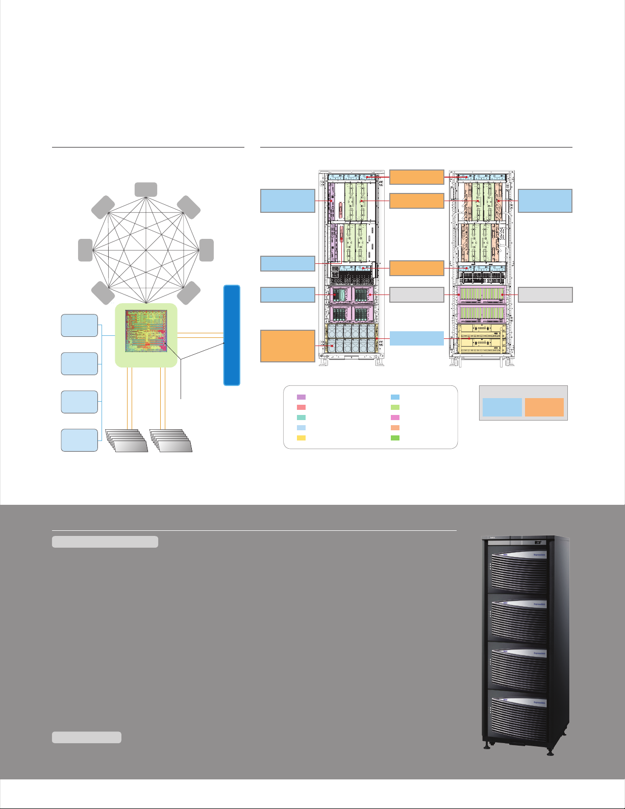
Internal Connections of the
n
Exp ress58 0 0/1000 Ser i es
System Hardware Layout of the Express5800/1000
n
Ser ies Server ( 1 320Xf)
Fan box
Service
Processor *
Clock card *
HDD Bay
Power
Distribution
Unit (PDU)
1
1
Service Processor
Clock card
HDD Bay
Power Distribution Unit
Power Bay
Ce ll ca rd
* R ed un da nt
configuration
available
Fan box
PCI box
* R ed un da nt
configuration
available
Power Bay
Fan box
Cell card
PCI box
Crossbar card
PCI slots
Crossbar
card
PCI slots
Hot Pluggable *
Fully
Redundant
*1 Redundancy is optional
*2 Ability to replace a failed component
without shutting down other partitions
2
N+1
Redundant
Mainframe-class RAS features
Reliability / Availability
• Dual-Core Intel® Itanium® processor:
Error handling of hardware and operating system through Machine Check Architecture (MCA)
• Memory mirroring:
• Partial Chipset degradation:
• Highly Available Center Plane:
no longer requires a system shutdown
• Complete modularization and redundancy:
continuous operation and serviceability
• Clock modularization, redundancy and 16 processor domain segmentation:
Minimizes downtime, and avoids multi partition shutdown due to clock failure
• Diagnostics of the error detection circuits:
• Enhanced error detection of the high-speed interconnect:
Intricate error handling through multi bit error detection and retransmission of error data
• Two independent power sources:
Serviceability
Autonomic reporting of logs with pinpoint prognosis of failed components allow for the realization of
•
mainframe-class platform serviceability
Continuous operation even in the event of a non-correctable error
Avoid multi-partition shutdowns resulting from chipset failures
System restoration after the replacement of a failed crossbar
Improvements in fault resilience,
Substantial strengthening of data integrity
Avoid system shutdown due to failures of the power distribution units
3
Page 4
Supercomputer-class Performan c e
Improved Inter/Intra-Cell memory data transfer
Increased Memory Bandwidth
High-speed/low latency Intra-Cell cache-to-cache data transfer
Very Large Cache (VLC) Architecture
High-speed/low latency Inter-Cell cache-to-cache data transfer
Dedicated Cache Coherency Interface (CCI)
Improved data transfer latency between Cell/Cell and Cell/IO
Crossbar-less configuration
Conventional Superscalar
RISC Processor
Original Source Code Original Source Code
Some level of parallelization is achieved however,
it is not maximized nor efficient
Parallel processing with
EPIC architecture
In the EPIC architecture, parallelization is run at compile time,
allowing for maximum parallelization with minimal scheduling.
Hardware
Partial HW
Parallelization
Intel® Itanium®
processor
supported compiler
Compiler
Sequential
Machine Code
Intel® Itanium® processor
source is parallelized at
compile time
Efficient parallel processing
is made possible due to the
thorough parallelization.
Features for performance improvement
Dual-Core Intel® Itanium® pr ocess o r and high -speed
inter/intra Cell cache-to-cache data transfer
At the heart of the Express5800/1000 series server is the
64 -bi t Dua l-C ore I nte l
®
Itanium® processor, redesigned for
even faster processing of larger data sets.
Th e sys te m has b een e qui pped wi th th e NEC d esi gn ed ch ips et,
3
“A
”, in order to improve performance by utilizing, to its full
ex ten t, th e mas siv e 24M B of ca che m emo ry th at ha s bee n bui lt
into the Dual-Core Intel
®
Itanium® processor
Techn olo gie s to in creas e cac he- to- cac he da ta tr ans fer, s uch
as the VLC architecture and CCI, have been implemented
to m axi miz e the p erf orm anc e for e nte rpr ise m iss ion c rit ica l
[1080Rf]
computing.
High processing power of the Dual-Co re I ntel® Itanium® processor
Du a l-Core, massi ve L3 cach e and EPIC ( E xplici tly Para llel Ins t ructio n Comput ing) architec t ure
The Dual-Core Intel® Itanium® pr oc e ss o r is In tel ’s first p rod uct ion
in t he It ani um
on one processor and also the first member of the Intel
processor family to include Hyper-Threading Technology, which
pr ov i de s f ou r t im e s the n umb er of a ppl ica tio n threa ds pr ovi ded b y
earlier single-core implementations.
With a maximum of 24MB of On-Die L3 cache, the Dual-Core Intel
Itanium
®
pr oc e ss o r fam ily w ith t wo co mpl ete 6 4-b it co re s
®
pr oc e ss o r exc els a t hig h vol ume d ata t ran sac tio ns.
®
Itanium®
®
[1320Xf]
[1160Xf]
EPIC architecture provides a variety of advanced implementations
of parallelism, predication, and speculation, resulting in superior
In str uct ion -Le vel P ara lle lis m (IL P) to h elp a ddr ess t he cu rrent
and future requirements of high-end enterprise and technical
workloads.
4
Page 5

VLC Architecture
CPU
L3
Cache
Memory
Cache
Memory
Cache
Memory
Cache
Memory
Cache
Memory
Cache
Memory
CPU
L3
L3 of other CPU
CPU
L3
L3 of other CPU
L3 of other
CPU on
different FSB
L3 of other CPU
on same FSB
L3 of other CPU on
different FSB
CPU
L3
Increased enterprise
applications
performance through
reduced cache memory
access latency
Very Large Cache (VLC) Architecture
Intel® Itanium® 2 processor
(Madison : L3 9MB)
Latency
Dual-Core Intel
®
Itanium® processor
(Montvale : L3 24MB)
Latency
CPU CPU CPU
Cache
Memory
Cache
Memory
CPU
Cache
Memory
Cache
Memory
Intel® Itanium® 2 processor
(Madison : L3 9MB)
Latency
High-speed
cache-to-cache
transfers
Direct CPU-to-CPU transfers
FSB
Data Size
Data Size
Memory
Dual-Core Intel® Itanium® processor
(Montvale : L3 24MB)
Latency
Split BUS Architecture
Data Size
CPU CPU CPU
Cache
Memory
Cache
Memory
CPU
Cache
Memory
Cache
Memory
chipset
Data transfer controller
Latency
degradation
(approx 3x)
This area increases
due to the increase in
cache size and
higher latency
Overhead from transferring
data through the chipset.
FSB FSBchipset
Higher cache memory
access latency.
Non-uniform
cache-to-cache data
transfer.
Inconsistent
performance.
Data Size
Higher
latency
(approx 3x)
This image does not depict actual numbers
Memory
chipset
Cache
Memory
Cache
Memory
Cache
Memory
Cache
Memory
Cache
Memory
Cache
Memory
L3 of
other CPU on
same FSB
CPU requesting the information
CPU storing the newest information
Memory that is storing location regarding
the memory
TAG memory (Manages cache line
information for all of the CPUs loaded on a
CELL card)
DIR Memory (Manages cache line
information for all of the memory loaded on
a CELL card)
Tag Based Cache Coherency
Directory Based Cache Coherency
Request is broadcasted to all CPU
simultaneously
The Express5800/1000 Series server
implements a dedicated connection (CCI)
for snooping
Access Directory to confirm the location of
the data first, then access the appropriate
cache memory
Memory
CPU
CPU
DIR
TAG
Memory
CPU CPU CPU CPU CPU CPU CPU
Memory
CPU CPU CPU CPU
Memory
Memory
CPU CPU CPU
DIR
CPU CPU CPU CPU
Memory
CPU CPU CPU CPU
DIR
CPU
DIR
Memory
Directory Based Cache Coherency
A3 Chipset
chip
set
chip
set
chip
set
chip
set
chip
set
chip
set
CPU CPU
chip
set
chip
set
chip
set
chip
set
chip
set
chip
set
chip
set
chip
set
CPU
chip
set
chip
set
CPU
TAG
CPU CPU
Memory
DIR
Performance
increase with
the A
3
chipset
TAG TAG TAG
CPU
Hi g h-spee d / low late ncy Intr a -Cell ca che-to -cache d a ta trans fer
The Express5800/1000 series server
im ple men ts th e VLC a rc hit ect ure, wh ich
al low s for l ow la ten cy ca che -to -ca che
da ta tr ans fer b etw een m ult ipl e CPU s
wi thi n a cel l.
In a s pli t BUS a rc h it e ctu re , for a c ach e-
to -c ach e dat a tr ans fer to ta ke pl ac e, th e
da ta mu st be p ass ed th rou gh a ch ips et.
Ho wev er, in the V LC ar chi tec ture,
da ta wi thi n the c ach e mem ory c an
be accessed directly by one another,
bypassing the chipset. This allows
fo r low er la ten cy be twe en th e cac he
me mor y, wh ich r esu lts i n fas ter d ata
transfers.
Dedicate d Cache Coherency Interface (CCI)
Hi g h-spee d / low late ncy Inte r- C ell cach e-to-c a che dat a t ransfe r
Another technology implemented in the Express5800/1000 series
server to improve cache-to-cache data transfer is the Cache
Coherency Interface (CCI). CCI, the inter-Cell counterpart of the
VL C arc hi t ec t ur e, al low s for a l owe r lat enc y cac he- to- cac he da ta
tr ans fer b etw een C ell s.
In for mat ion c ont ain ing t he lo cat ion a nd st ate o f cac hed d ata i s
re qu i re d for t he CP U to ac ces s the s pec ific d ata s tor ed in c ach e
me mor y. By a cce ssi ng th e cac he me mor y acc o rd ing t o thi s
in for mat ion , the C PU is a ble t o ret rie ve th e des ired da ta.
Two main mechanisms exist for cache-to-cache data transfer
be twe en Ce lls , dir ect ory b ase d and TA G bas ed ca che c ohe re ncy.
Th e cac he in for mat ion , des cri bed a bov e, is s tor ed in e xte rna l
me mor y (DI R mem ory ) for t he di rec tor y bas ed, a nd wi thi n the
chipset for the TAG based mechanisms.
In a d ire ct o ry b a se d s yst em, t he requ est or CP U wil l firs t acc ess t he
ex ter n al me mor y to co nfir m the l oca tio n of th e cac hed d ata , and
th en wi ll ac ces s the a pprop ria te ca che m emo ry. On the o the r han d,
in a TA G bas ed sy ste m, th e req ues tor C PU broa dca sts a r equ est t o
al l oth er ca che s imu lta neo usl y via TA G.
Crossbar-less configuration
Im p rove d d ata tran sfer lat ency through di rect at t ached Ce ll config uratio n
Wit hin t he Ex press 580 0/1 000 s eri es se rve r lin eup , the 1 0 80 R f
has been able to lower the data transfer latency by removing the
cr os s ba r a nd d i re ctl y con nec tin g Cel l to Ce ll, a nd Ce ll to P CI bo x.
The benefit of the TAG based mechanism, thus implemented in
the Express5800/1000 series server, is that by accessing the
TAG , unn ece ssa ry in qui rie s to th e cac he me mor y are fi lte re d for a
sm oot her t ran sfe r of da ta. F urt her mor e, th e Exp re ss5 800 /10 00
series server includes a dedicated high-speed cache coherency
in ter fac e (CC I) wh ich i s use d to co nne ct th e Cel ls di rec tly t o
one another without using a crossbar. This interface is used for
broadcasting and other cache coherency transactions to allow for
even faster cache-to-cache data transfer.
Ev en wi th th e cro ss b ar-l ess c onfi gur ati on, v irt ual iza tio n of th e Cel l
ca rd a n d I/ O b ox h a s be e n re tai ned a s not t o dim ini sh co mpu tin g
and I/O resources.
5
Page 6

Mainframe-class RAS Features
Clustering
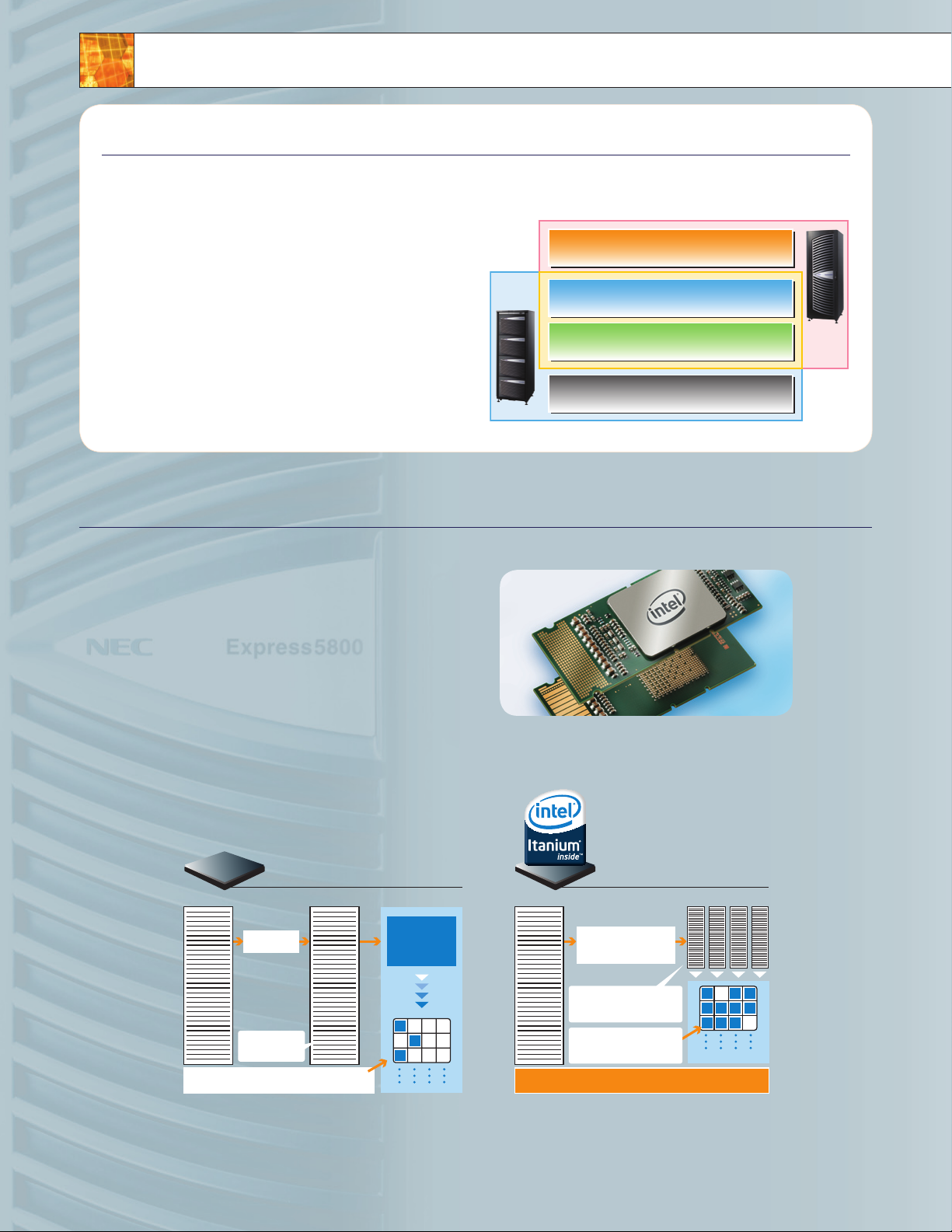
Dependable Server Te chnology
Continuous operations through failures
Redundant components, error prediction and error
correction allows for continuous operation
Minimized spread of failures
Technology to minimize the effects of hardware failures on
the system. Reduction of performance degradation and
multi-node shutdown
Smooth recovery after failures
Ability to replace failed components without
shutting down operations
Improved system availability
Improved reliability and availability as a stand alone server
Mainflame
Level
Conventional
open server
Level
PC Server
Level
Reliability Availability Serviceability
Center
plane
Chipset
Clock
Core I/O
PCI card
Memory
CPU
L3 cache
Power
HDD
No chipset on the center plane
ECC protection of main
data paths Intricate error
detectionof the high-
speed interconnects
Partial chipset degradation/
Dynamic recovery
Hot Pluggable
*
4
Hot Pluggable
*
4
Hot Pluggable
*
4
Hot Pluggable
*
4
Hot Pluggable
*
4
Hot Pluggable
*
4
Duplexed*
1
16 processor domain
segmentation
*
2
Core I/O Relief
ECC protection
SDDC Memory
Memory
Mirroring*
1
Intel® Cache Safe
Technology*
3
N+1 Redundant
Two independent
power sources
Software RAID
Hardware RAID
*1 Available only on the 1320Xf/1160Xf
*2 Available only on the 1320Xf
*3 Intel
®
technology designed to avoid cache based failures
*4 Replacement of failed component without shutting down other partitions.
Application Layer
Operating System
The OS logs the error, and then starts the re covery process
Hardware
CPU and chipset ECC and parity protection
The Firmware and OS aid in the correction of complex platform errors to restore the system
Error details are logged, and then a report flow is defined for the OS
Detects and corrects a wide range of hardware errors for main data structures
Firmware
Seamlessly handles the error
RAS Design P hilosophy
Realization of a mainframe-class continuous operation through the pursuit of
re liabi l ity and av ailabi lity in a si n gle serv er const ruct
Ge ner all y, in o rde r to ac hie ve reli abi lit y a nd a v ai l ab i li t y on an
open server, clustering would be implemented. However,
cl ust eri ng co mes w ith a p ric e ta g. To keep c ost s at a mi nim um,
the Express5800/1000 series servers were designed to
ac hie ve a hi gh le vel o f rel iab ili ty an d ava ila bil ity, but w ith in a
single server.
Th e Exp re s s5 8 00 / 100 0 ser ies s erv er’s po wer ful R AS fe atu res
we re d e ve l op e d th rou gh th e pur sui t of de pen dab le se rve r
technology.
Continuous operations throughout failures; minimize the
sp re a d of f a il u re s; an d smo oth r eco ver y aft er fa ilu re s wer e
go als s et fo rth w hic h lea d to im ple men tat ion o f tec hno log ies
such as memory mirroring, increased redundancy of intricate
co mpo nen ts, a nd mo dul ari za tio n. Th rou gh th ese t ech no log ies
a ma inf ram e lev el of c ont inu ous o per ati on wa s ach iev ed.
The Dual-C ore Intel® Itanium® processor MCA
(Machine C heck Architecture)
Th e f ramewo rk for hardware, firmwa re and OS e rror ha ndling
The Dual-Core Intel® Itanium® processor, designed for high-end
enterprise servers, not only excels in performance, but is also
ab und ant i n RAS f eat ure s. At t he co re o f the p roc ess or’s RA S
feature set, is the error handling framework, called MCA.
MC A pro vi d es a 3 s t ag e e rror ha ndl ing m ech ani sm – ha rdw are,
fir mwa re , a nd o p er a tin g sys tem . In th e firs t sta ge, t he CP U and
chipset attempt to handle errors through ECC (Error Correcting
Co de) a nd pa rit y pro tec tio n. If t he er ro r can n ot be h and led b y
th e har dw a re , it is t hen p ass ed to t he se con d sta ge, w her e the
fir mwa re a t te m pt s t o re sol ve th e iss ue. I n the t hir d sta ge, i f the
error can not be handled by the first two stages, the operating
system runs recovery procedures based on the error report
an d err or l o g th a t wa s rec eiv ed. I n the e ven t of a cr iti cal e rro r,
th e sys tem w ill a uto mat ica lly r ese t, to s ign ific ant ly redu ce th e
possibility of a system failure.
6
Page 7

Memory Mir ro ring
Memory
Image
Unit of degradation
on the Express5800/
1000 Series
Data 0
Data 2
Data 1
Data 3
Data 0
Data 2
Data 1
Data 3
Cell
Controller
Memory
I/F
Memory
Controller
Memory
I/F
Memory
Controller
Memory
I/F
Memory
Controller
Memory
I/F
Memory
Controller
Components covered by
the memory mirroring
CPUCPU CPU CPU
Mirro r
Mirro r
Components covered by
the standard chip sparing
PCIBox
0
0
PCIBox
1
1
0
1
Sub
Unit
Sub
Unit
Crossbar
Controller
A
Sub
Unit
Sub
Unit
Crossbar
Controller
B
Sub
Unit
Sub
Unit
Sub
Unit
Sub
Unit
Sub
Unit
Cell 1
1
Cell 0
0
Partial
degradation
Failure
n specifies the partition number
Sub-units within the chipset
Additional sub-sets exist in
actuality
Not affected
Failure occurs at the sub-unit of
the crossbar controller.
Partition 0 is shutdown so that the
failed component can be isolated.
Partition 0 is rebooted
Continuous operation even in the event of a non-correctable memory error
The Express5800/1000 series server supports high-level memory
RAS features to ensure that the server can rapidly detect memory
er ro r s, r edu ce mu lti -bi t err ors a nd co nti nua lly o per ate e ven i n
the event of memory chip or memory controller failures. Memory
scan, memory chip sparing (SDDC*) and memory scrubbing are
examples of those features.
A me mor y sca n is ru n on al l loa ded m emo ry mo dul es at e ach O S
boot. If the system detects a memory failure, the failed component
is immediately isolated and detached from the system preventing
po ssi ble d own tim e dur ing b usi nes s ope rat ion s.
Chip sparing (SDDC*) memory is a memory system loaded with
se ver al DR AM ch ips t hat c an co rre ct er ro rs at t he ch ip le vel . If
a fa ilu re w e re t o occ ur in t he me mor y, th e err or ca n be co rre ct e d
im med iat ely t o all ow fo r con tin uou s ope rat ion .
Me mor y scr ubb ing c hec ks me mor y con ten t reg ula rly ( eve ry fe w
mi lli sec ond s) du rin g ope rat ion w ith out a ffe cti ng pe rfo rma nce .
Wh en an e rro r is d e te c ted , it is c orrec ted a nd th en re por ted .
Th e scr ubb ing f unc tio n is ef fec tiv e in de tec tin g error s in a ti mel y
ma nne r whi ch ul tim ate ly re sul ts in t he redu cti on of m ult i-b it er ror s.
Memory mirroring takes place continuously, where the same data
is written onto 2 separate memory blocks instead of 1 (available
on ly on t he 11 60X f and 1 320 Xf) . In th e eve nt of a n on- cor rec tab le
er ro r, due t o the f act t hat t he da ta ex ist s on tw o ind epe nde nt
blocks, operations are able to continue without interruption.
This construct allows for continuous operation through all non-
correctablememory errors, not limited to the memory themselves,
bu t als o in th e mem ory i nte rfa ces a nd th e in me mor y con tro lle rs.
* Si ng le D ev ic e Da ta C or rec tion
Partial Ch ipset degradation
Avoid multi-partition shutdowns resulting from chipset failures
In c ert ain i nst anc es wh en mu lti ple s erv er pa rti tio ns sh are a
co mmo n cro ss b ar c o ntrol ler, eff ect s of a si ngl e par tit ion f ail ure
ma y re s ul t i n a mu l ti - par tit ion s hut dow n. To res olv e thi s iss ue, t he
Ex pre ss 5 80 0 /1 0 00 se rie s ser ver s hav e bee n des ign ed to a llo w for
th e par tia l deg rad ati on of c hip set s.
Wit hin e ach o f the L SI ch ips , whi ch ma ke up t he ch ips et, m ult ipl e
LSI sub-units exist. These sub-units are connected to other sub-
un its l oca ted o n sep ara te LS I chi ps. T he co mbi ned s ub- uni ts
to get her m ake u p sin gle p art iti on. I f an er ror w ere to oc cur o n an
LS I sub -un it, t hat s ub- uni t alo ne ca n be de gra dat ed to i sol ate t he
fa ilu re t o a s in g le p a rti tio n, th us prev ent ing t he fa ilu re to s pread t o
other partitions.
Fu rth erm ore , th e d own ed pa rti tio n can a uto mat ica lly reb oot
itself, after isolating the failed subsystem, to resume operations
in a d egr ada ted m ode w ith out t he in ter ven tio n of a sy ste m
administrator. This is made possible, on the Express5800/1000
se rie s ser ver s, by t he re dun dan t pat hs be twe en th e Cel ls an d the
IO.
7
Page 8

Mainframe-class RAS Features
Down
Failure
Crossbar
Controller
(LSI)
Crossbar
Card
Crossbar Controller Mudularization
Only the node that is linked directly to the failed crossba
r
will be temporarily shutdown
The failed crossbar
card can be
replaced without halting
other business
operations.
Cell
Cell
Cell
Cell
Cell
Cell
Cell
Cell
Cell
Cell
Cell
Cell
Failure
Down
Operation 1
Node 1
Operation 2
Node 2
Operation 3
Node 3
Operation 4
Node 4
PCI box PCI box PCI box PCI box PCI boxPCI box
Cell card
CPU CPU
CPU CPU
Memory
Memory
Cell card
CPU CPU
CPU CPU
Memory
Memory
Cell card
CPU CPU
CPU CPU
Memory
Memory
Cell card
CPU CPU
CPU CPU
Memory
Memory
Cell card
CPU CPU
CPU CPU
Memory
Memory
Cell card
CPU CPU
CPU CPU
Memory
Memory
Cell card
CPU CPU
CPU CPU
Memory
Memory
Clock Card
Cooling fan (N+1 redundant)
Power supply (N+1 / 2N redundant)
Service Processor
Clock Card
Crossbar Card
Crossbar Card
Crossbar Card
Crossbar Card
Spare
Cell Card
Redundant Crossbar
Redundant Clock Module
(Redundancy or Segmentation)
Redundant service processor
N+1 redundant cooling fan
N+1 redundant power supply
Quick recovery is possible
with a spare CELL card
1080Rf is crossbar-less
Full redundancy is available on the
1320Xf/1160Xf. Segregation is available
on the 1320Xf
Available on the 1320Xf/1160Xf
2N is included in the 1320Xf, and is offered
as an option on the 1160Xf/1080Rf
* This picture illustrates a 1320Xf
Front Side Back Side
Power
Distribution
Unit
Fan box
Fan box
Crossbar
card
Cell card
PCI Module
HDD Module
PCI Box
Service
Processor
Fan box
Fan box
Clock
card
Cell card
Highly Available Center Plane
Sy s tem re s torati on after t he repl acemen t o f a failed c rossb ar card
no l o nger re quire s a planne d system d owntim e
The Express5800/1000 series server has separated and
mo dul ari zed t he cr oss bar c ont ro lle r whi ch or din ari ly wo uld res ide
on the system center plane. By moving the crossbar controller off
of t he ce nte r pla ne, a r edu cti on in c ent er pl ane f ail ures ha s bee n
realized.
In t he un lik ely e ven t of a cr oss bar f ail ure, on ly th e par tit ion t hat i s
li nke d to th e cro ss b ar wi ll be t emp ora ril y shu tdo wn, a llo win g for
the other partitions to continue operations uninterrupted, including
during the replacement of the crossbar card.
(The 1080Rf has a crossbar-less configuration.)
Complete m odularization and redu ndancy
Improvements in fault resilience, continuous operation and serviceability
Ma jor c omp one nts o f the E xpr ess 580 0/1 000 s eri es se rve rs ha ve
been modularized, allowing for better serviceability and easy
re pl a ce m en t i n th e e ven t of a co mpo nen t fai lure.
Furthermore, to minimize the existence of single point of failure,
many of these modules have redundancy, allowing for continuous
operations (fault resilience).
8
Sa mpl e: Exp ress 580 0/13 20Xf
Page 9

Modulari zation, redundancy and d omain segmentation of the system clock
Express5800/1000 Series
Redundant: Active, Standby
chipset
chipset
Clock
Distribution
Clock
Module
Clock
Module
Clock
Module
Clock
Module
Clock
Module
Clock
Module
Clock
Module
Hot
pluggable
Not hot
pluggable
Redundant Configuration A
Redundant Configuration A
Redundant Configuration B
Express5800/1000 Series
Redundant
Available on the 1320Xf/1160Xf
16 processor Domain Segmentation
Available on the 1320Xf
Redundant Configuration B
*
1
SPOF
Redundant: Active, Standby Redundant: Active, Standby
16 Processor Domain
Segmentation
Clock
Module
Clock
Module
16 Processor
Domain
16 Processor
Domain
chipset
chipset
chipset
chipset
chipset
chipset
chipset
chipset
chipset
chipset
chipset
chipset
chipset
chipset
Replacement of failed
component without
system halt
Minimized spread
of failure
*1: Hot plugging of the redundant oscillator is possible, however the hot plugging of the single clock driver is not possible
Clock
Distribution
Clock
Distribution
Clock
Distribution
Clock
Distribution
Clock
Distribution
Cell card
CPU CPU CPU CPU
Memory
Controller
Memory
Controller
Memory
Controller
Memory
Controller
Crossbar Card
Built-in high-speed error
check for inter-chipset
paths
PCI BOX
I/O
Router
I/O
Router
Cell
Controller
Crossbar
Controller
Crossbar
Controller
Crossbar
Controller
Crossbar
Controller
To
other CELL
controller
Minimizes downtime, and avoids multi-partition shutdown due to clock failure
Th ro ugh m odu lar iza tion an d red und an cy, syst em do wnt ime , due t o
cl ock f ail ures, h ave b een m ini miz ed. T he Ex press 580 0/1 000 s eri es
se rve r has t ake n it on e ste p fur the r. In m any c ase s, wh e n a sy s te m
is said to have a redundant clock, in actuality, only the oscillator
is r ed u nd a nt . I nt e gra l clo ck di str ibu tio n mec han ism s suc h as th e
cl ock d riv er or t he am pli fier a re, m any t ime s, no t re dun dan t. Su ch
a co nst ruc t le ads t o the e xis ten ce of s yst em s ing le po int o f fai lures .
The Express5800/1000 series servers have redundancy in not only
th e osc ill ato r, bu t als o in th e clo ck di str ibu tio n m ec h an i sm s s o tha t
sy ste m dow nti me ca n be mi nim ize d.
Th e 132 0Xf s yst em al low s for t he di vis ion o f the s yst em in to tw o
16 processor segments, where one segment utilizes one system
clock, and the other 16 processor segment utilizes the remaining
sy ste m clo ck. A f ail ure i n a sys tem c loc k the re for e, wi ll no t re sul t
in s hut dow n of th e ent ire s yst em.
Diagnost ics of the error detection circuits
Substantial strengthening of data integrity
Main data paths of the A3 chipset on the Express5800/1000 series
se rve rs ha ve be en pr ote cte d by EC C. Wh en a si ngl e bit e rror is
de tec ted , a har dw a re e rro r cor re cti on is c arr ied o ut. F urt her mor e,
pa ths b etw een t he A
detection, and resending of errored data.
In a ddi tio n to ma int ain ing d ata i nte gri ty th rou gh th ese R AS
features, the Express5800/1000 series server has the ability to
ru n dia gno sti cs on i ts ow n err or de tec tio n circu its . Dur ing e ver y
sy ste m boo t, al l err or de tec tio n circu its a re di agn ose d for p oss ibl e
fa ilu re s . Wit hou t thi s fea tur e, a fa ilu re i n the se ci rcu its c oul d re s ul t
in t he in abi lit y to de tec t err ors d uri ng sy ste m ope rat ion .
3
chipset interfaces support multi-bit error
9
Page 10

Mainframe-class RAS Features
Customer
Environment
Diagnostics Agent
Diagnostics of retry tendency and
confirmation of whether threshold
was exceeded
Service
Processor
Manager
Preventive Maintenance,
Failed Component Replacement
Maintenance Group
The error information summary
is analyzed to determine the
cause of the failure.
The development team may
be contacted for assistance.
Encrypted message
Development Group
The Error information
is sent via email
If required, the detail log is analyzed
further by the development groups
Hard
ware
Diagnostics
Agent
Log
Mail
Log
Mail
Internet
Log
A detailed hardware error log
including transaction history is
collected.
chipset
Without Check Features
Logic Circuits
ECC
Failure
Bad Data
Without Check Features
Logic Circuits
ECC
Data
Data
Failure
Unable to detect error
Circuit
Check
Error Detected
1 bit Error
Error Detection
Circuits
Error Detection
Circuits
Bad data, resulting from a simple error
such as a single bit error, can not be
blocked if a failure exists within the
error detection circuits themselves.
Diagnostics of the error detection
circuits at every system boot
insures data integrity.
Error
Reporting
Error
Reporting
Enhanced e rror detection of the high -speed interconnect
In t ricate e rror ha ndling t h roug h multi- b it erro r detect ion
and resending of errored data
Since higher speed interconnects are implemented to increase
system performance, there are higher probabilities that
in ter fer en c e no i se wi ll ca use e rrors o ccu rri ng al ong t hes e
interconnects. One method of handling these interconnect errors
wo uld b e to di sab le th e err ored in ter con nec t and o per ate i n a
degradated mode.
In a ddi tio n to ab ove m eth od, t he Ex pre s58 00/ 100 0 ser ies s erv ers
ha ve im ple men ted a m eth odo log y pre val ent i n sup ercom put ers ,
where by intricate multi-bit error detection is carried out, and
er ro red d ata i s res ent u pon d ete cti on of a n error. Thi s a ll o ws
the Express5800/1000 series servers to handle the intermittent
er ro r s wh i ch oc cur a lon g the h igh -sp eed i nte rc onn ect s, wi tho ut
impacting the system performance.
Two independent power sources
Av oid sys t em shutd own due to f ailures of the po w er distr ibutio n units
The previous 32 processor and the 16 processor models supported
having two independent power supplies, where the 8 processor
mo del d id no t. Th is fe atu re is n ow av ail abl e on th e new 8 p ro ces sor
sy ste m (10 80R f) so t hat t he sy ste m can c ont inu e ope rat ion s eve n
in t he ev ent o f a fai lur e wit h in th e pow er di str ibu tio n uni t.
Im ple men tat ion o f an Un int err upt ibl e Pow er Su ppl y (UP S) ca n
further increase availability. The two independent power source
fe atu re i s a s ta n da rd fe atu re on t he 13 20X f and i s ava ila ble a s an
op tio nal f eat ure f or 11 60X f and 1 080 Rf.
Autonomi c re porting of error logs with p inpoint prognosis
of failed co mponents
Re a lizati on of a main frame- c lass pla tform se rvicea b ility
Th e Exp re s s5 8 00 / 100 0 ser ies s erv ers a re e qui ppe d wit h a ser vic e
pr oc e ss o r wh i ch p roc ess s erv er ma nag eme nt an d pla tfo rm er ror
handling. The service processor can be considered the core
component which supports the RAS features of the system. One
fe atu re o f t he s e rv i ce proc ess or is i ts ab ili ty to a nal yze d eta il lo gs
(B ID: b uil t-i n dia gno sis ) whi ch ar e col lec ted b y the c hip set i n the
ev ent o f an er ro r. The B ID is a ble t o dia gno se th e loc ati on of t he
er ro r, and w ill p inp oin t the req uir ed FR U (Fi eld R epl ace abl e Uni t)
so that the time required to replace the component and recover the
sy ste m, ca n be mi nim ize d.
In t he ev ent o f a fai lur e, th e Exp re ss5 800 /10 00 se rie s ser ver s
also have the capability to automatically send detailed error logs
to m ain ten anc e per son nel , ena bli ng us t o fur the r les sen t he ti me
required to resolve a system error. Furthermore, to minimize
th e pos sib ili ty of a c rit ica l err or, the di agn ost ics e ngi ne is a ble t o
proactively predict errors rather than just react to errors.
10
Page 11

Flexibility and Operability
�
Intel® Itanium® Processor Family Roadmap
Intel® Itanium® 2
processor 1GHz,
3MB L3
Tukwila*
2002 2003 2004 2006 2007 Future
Intel® Itanium® 2
processor 1.5GHz,
6MB L3
Intel
®
Itanium® 2
processor 1.6GHz,
9MB L3
Dual-Core Intel
®
Itanium® 2
processor 1.6GHz,
24MB L3
Dual-Core Intel
®
Itanium®
processor 1.6GHz,
24MB L3
* Intel codenames
Insufficient computing
resources
Cell card
PCI box
Cell card
PCI box
Cell card
PCI box
Crossbar
Cell card
PCI box
Cell card
PCI box
Cell card
PCI box
Crossbar
Resource pool
Insufficient I/O
resources
Problem resolved by adding
additional I/O resources
Problem resolved by adding
additional computing resources
Pursuit of flexibility and operability in a system
— Fle xible re s ource vi r tualizat i on using floa ting I/O for i m proved o p erabilit y
Investme nt Protection
Smooth migration to future processors
The Express5800/1000 series servers now support the Dual-Core
®
Intel
Itanium® pr oc e ss o rs wi th tw o com ple te 64 -bi t cores o n
each processor. From the beginning of development, state-of-the-
ar t tec hno log ies h ave b een b uil t int o the I tan ium
answer to the stringent levels of throughput, scalability, reliability,
and availability that are required by the server platforms, and
al so pr ov i de d t op - lev el pe rfo rma nce . Wit h the d epl oym ent o f t he
pr es e nt d a y Du a l- C ore sys tem , a smo oth m igr ati on to f utu re mu lti -
core systems can be assured.
®
pr oc e ss o rs to
Resource virtualization through floating I/O
Fl e xible resource manag ement al lows for robust s e rver vir tualiz ation
The Express5800/1000 series employ floating I/O to allow for
th e flex ibl e com bin ati on of C ell c ard s and P CI bo xes ( I/O ). Th e
co mpu tat ion al an d I/O r eso urces c an be v irt ual ize d, al low ing f or
th e flex ibi lit y to re all oca te sy ste m re sou rce s int o the m ost o pti mal
co nfig ura tio n acc ord ing t o ope rat ion o r loa d.
Fu rth erm ore , wi t h the e xis ten ce of a s pare Ce ll ca rd, t he sy ste m
ca n swa p the f ail ed Ce ll ca rd wi th th e spa re i n the e ven t of a fa ilu re,
and reboot the system so that business operation can resume
without loosing valuable computational resources.
Multi OS sup port / Rich application lineup
Windows® op e rating s ystem an d Linux op e rating s ystems s upport e d
Along with the industry’s prevalent Microsoft® Windows® operating
system,the Express5800/1000 series servers also support the
Linux operating system. By dividing the system into multiple
partitions, it is possible to support multiple operating systems
wi thi n a sin gle s erv er.
With the inception of the Itanium
whose main objective is to promote the advancement of
®
Itanium
on the Itanium
-b ase d sol uti ons , app lic ati ons s tre aml ine d to pe rfo rm
®
-b ase d ser ver s, su ch as t he Ex pre ss5 800 /10 00
series servers, have increased considerably.
®
So lut ion s All ian ce (I SA) ,
Superior s tandard chassis configuration
Small footprint and a highly scalable I/O
With the ability to load 32 Dual-Core Intel
(1 320 Xf) i nto a n ind ust ry st and ard 1 9-i nch r ack f oot pri nt, t he
Express5800/1000 series server has proved to have the industries
hi ghe st le vel o f per for man ce pe r uni t are a. Be cau se ad dit ion al
sp ace i s not r eq u ir ed in t he da tac ent er in o rde r to ac com mod ate
®
Itanium® pr oc e ss o rs
the Express5800/1000 series server, it is an ideal candidate for
re pl a ce m en t o r co n sol ida tio n of ol der s yst ems .
Th e 108 0Rf i s a ver y com pac t 8U mo del w hic h can s upp ort u p to 8
in ter n al 3. 5 inc h HDD a nd 16 P CI ca rd s.
11
Page 12

NEC Express5800/1000 series Specifications
Model
1080Rf
1160Xf
1320Xf
CPU
Processor
Du al C ore I ntel® Itanium® processor
Intel® Processor Number
9120N
9140N
9150N
9120N
9140N
9150N
9120N
9140N
9150N
Clock frequency
1.42GHz
1.60GHz
1.60GHz
1.42GHz
1.60GHz
1.60GHz
1.42GHz
1.60GHz
1.60GHz
Maximum Number of CPU(core)
8 (16)
16 (32)
32 (64)
On-chip cache
L1 Cache/core
16 KB ( I) / 1 6K B (D )
L2 Cache/core
1M B (I ) / 25 6K B (D )
L3 Cache/core
6MB
9MB
12MB
6MB
9MB
12MB
6MB
9MB
12MB
L3 Cache/CPU
12MB
18MB
24MB
12MB
18MB
24MB
12MB
18MB
24MB
Maximum Memory Capacity
128GB
512GB
1TB
Maximum Number of I/O slots
163232/64
In te rn al D is k
Drives
Di sk B ay
81616/32
Maximum Capacity
2, 40 0G B (3 00 GB * 8 )
4, 80 0G B (3 00 GB * 1 6)
9, 60 0G B (3 00 GB * 3 2)
LAN Interface
10/100Base-T (For Management console)
Cabinet Type
Ra ck m ou nt ( 8U )
Standalone (37U)
Di me ns io n (W * D * H )
44 1 x 85 7 x 35 1 mm
60 0 x 10 70 x 1 80 0 mm
Weight
110kg
464kg
563.4kg
Power Supply
AC 200-240V / 50Hz-60Hz
ES Tem pe ra tu re /H um id it y
5 – 35 d eg ree C / 2 0 – 80 % RH (o pera ti on ), 5 – 4 5 de gr ee C / 8 - 80 % R H (n on -o pe ra ti on ) wi th ou t co nd en sa ti on
Supported OS
Microsoft® Windows Server® 2008 for Itanium-based Systems
Microsoft
®
Windows Server® 20 03 E nt er pr is e Ed it io n / Da ta ce nt er E di ti on
Red Hat Enterprise Linux
n
* NEC is a registered trademark and Empowered by Innovation a trademark of NEC Corporation and/or one or more of its subsidiaries. All are used under license. * Intel, Intel logo, Itanium and
Itanium inside are trademarks or registered trademarks of Intel Corporation or its subsidiaries in the United States and other countries. * Microsoft and Windows are registered trademarks or
trademarks of the US Microsoft Corporation in the United States and other countries. * Red Hat and Shadow Man logos are registered trademarks or trademarks of Red Hat Inc. in the United States
and other countries. * Linux is a trademark or registered trademark of Linus Torvalds in the United States and other countries. * All other trademarks and registered trademarks are the property of
their respective owners.
Safety notes
Please read carefully before use and observe the cautions and prohibitions in the instruction, installation, planning, operations and other manuals.
Incorrect usage may cause fire, electric shock, or injury.
Company names and product names used in this catalogue are trademarks or registered trademarks of the respective companies.
If this product (including the software) comes under the regulations of Foreign Exchange and Foreign Trade Law as a regulated article or other item, observe the procedures (such as application for
export permission) required by the Japanese government when taking the product out of Japan.
The colors of the products in this catalogue may be slightly different from the actual colors. Specifications are subject to change without prior notice for the purpose of improving the product.
© 2008 NEC Corporation. All rights reserved.
Information in this document is subject to change without notice.
Cat .No.E07H01
 Loading...