

Page 1

EXPRESS5800/120Lg
()
■■■■■■■
■■■■■■■
■■■■■■■
■■■■■■■
■■■■■■■
■■■■■■■
Service Guide
■■■■■■■
■■■■■■■
■■■■■■■
■■■■■■■
■■■■■■■
■■■■■■■
■■■■■■■
■■■■■■■
Page 2

Page 3

Proprietary Notice and Liability Disclaimer
The information disclosed in this document, including all designs and related materials, is
the valuable property of NEC Solutions (America), Inc. and/or its licensors. NEC Solutions
(America), Inc. and/or its licensors, as appropriate, reserve all patent, copyright and other
proprietary rights to this document, including all design, manufacturing, reproduction, use,
and sales rights thereto, except to the extent said rights are expressly granted to others.
The NEC Solutions (America), Inc. product(s) discussed in this document are warranted in
accordance with the terms of the Warranty Statement accompanying each product.
However, actual performance of each product is dependent upon factors such as system
configuration, customer data, and operator control. Since implementation by customers of
each product may vary, the suitability of specific product configurations and applications
must be determined by the customer and is not warranted by NEC Solutions (America), Inc.
To allow for design and specification improvements, the information in this document is
subject to change at any time, without notice. Reproduction of this document or portions
thereof without prior written approval of NEC Solutions (America), Inc. is prohibited.
Trademarks
Windows 2000 is a registered trademark of Microsoft Corporation.
Intel is a registered trademark of Intel Corporation.
Xeon is a trademark of Intel Corporation.
All other product, brand, or trade names used in this publication are the trademarks or registered
trademarks of their respective trademark owners.
PN: 456-01673-000 April 2003
Copyright 2003
NEC Solutions (America), Inc
10850 Gold Center Drive, Suite 200,
Rancho Cordova, CA 95670
All Rights Reserved
Page 4

Page 5

Contents
Proprietary Notice
Using This Guide
Text Conventions.................................................................................................................. x
Related Documents .............................................................................................................. xi
Safety Notices.....................................................................................................................xii
Safety Notices for Users Outside of the U.S.A. and Canada........................................xiii
Care and Handling.............................................................................................................. xiv
1. System Overview
Overview............................................................................................................................ 1-2
System Features .................................................................................................................1-3
System Chassis Features....................................................................................................1-4
Front View....................................................................................................................1-4
Front View (Door Opened)...........................................................................................1-5
Rear View ..................................................................................................................... 1-7
Internal View ................................................................................................................ 1-9
System Board Features................................................................................................1-10
Standard Features.............................................................................................................1-12
Xeon™ Processors......................................................................................................1-13
System Memory..........................................................................................................1-13
PCI Riser Slots............................................................................................................1-13
Video Controller .........................................................................................................1-13
SCSI Controller...........................................................................................................1-13
Network Controller.....................................................................................................1-13
Keyboard and Mouse.................................................................................................. 1-14
RJ-45 Serial Port.........................................................................................................1-14
ACPI ...........................................................................................................................1-14
System Board Management Controller (BMC)..........................................................1-15
Power Supplies................................................................................................................. 1-16
Peripheral Bays................................................................................................................1-16
System Functions.............................................................................................................1-17
Degradation Feature.................................................................................................... 1-17
Remote Power-On Feature (Wake On LAN)..............................................................1-17
AC-LINK Feature.......................................................................................................1-17
Security ............................................................................................................................ 1-18
Security with Mechanical Locks and Monitoring....................................................... 1-18
Software Locks via the System Setup Utility .............................................................1-18
2. Setting Up the System
Overview............................................................................................................................ 2-2
Selecting a Site...................................................................................................................2-2
Unpacking the System........................................................................................................2-3
Making Connections ..........................................................................................................2-3
Connecting the Power Cord...............................................................................................2-5
Using the System................................................................................................................2-5
Opening the Front Door of the Tower Cabinet............................................................. 2-6
Contents iii
Page 6

Powering On Your System............................................................................................2-7
Powering Off the Server System...................................................................................2-8
Forcing a Power Shutdown ...........................................................................................2-8
3. Configuring Your System
Configuring Your System...................................................................................................3-2
BIOS Setup Utility..............................................................................................................3-3
Using the BIOS Setup Utility........................................................................................3-3
BIOS Setup Configuration Settings...............................................................................3-4
Main Menu....................................................................................................................3-5
Primary and Secondary Master and Slave IDE Submenus....................................3-6
Processor Settings Submenu..................................................................................3-6
Advanced Menu ............................................................................................................3-7
PCI Configuration Menu.......................................................................................3-8
Onboard NIC 1 / Onboard NIC 2 Submenu..........................................................3-9
Onboard SCSI Submenu........................................................................................3-9
Onboard Video Submenu ......................................................................................3-9
Peripheral Configuration Submenu .......................................................................3-9
Memory Configuration Submenu........................................................................3-10
Advanced Chipset Control Submenu...................................................................3-10
Security Menu.............................................................................................................3-11
Server Menu................................................................................................................3-12
System Management Submenu............................................................................3-13
Console Redirection Submenu............................................................................3-14
Event Log Submenu............................................................................................3-14
Boot Menu...................................................................................................................3-15
Boot Device Priority Submenu............................................................................3-15
Hard Drives Submenu .........................................................................................3-15
Removable Devices Submenu.............................................................................3-16
Exit Menu....................................................................................................................3-16
SCSISelect Utility.............................................................................................................3-17
Running the SCSISelect Utility...................................................................................3-17
Adaptec SCSI Utility Configuration Settings..............................................................3-18
SCSI Disk Utilities......................................................................................................3-19
Exiting Adaptec SCSI Utility......................................................................................3-20
Configuring the RAID Controller.....................................................................................3-21
Configuring System Board Jumpers.................................................................................3-22
Before You Begin........................................................................................................3-22
Moving System Board Jumpers ..................................................................................3-23
Clearing CMOS...........................................................................................................3-23
Clearing and Changing the Passwords........................................................................3-24
4. Disassembly and Reassembly
General Information ...........................................................................................................4-3
Static Precautions ...............................................................................................................4-3
Equipment Log...................................................................................................................4-3
Tools Recommended for Upgrading Your System.............................................................4-4
Preparing Your System for Disassembly and Reassembly.................................................4-4
Side Access Panel...............................................................................................................4-5
Processor Air Duct..............................................................................................................4-8
Removal.........................................................................................................................4-8
Installation.....................................................................................................................4-9
iv Contents
Page 7

Modifying the System Board...........................................................................................4-10
Replacing the Real-time Clock Battery....................................................................... 4-10
Removing and Installing a Processor..........................................................................4-13
CPU Installation..................................................................................................4-14
CPU Removal......................................................................................................4-19
DIMMs........................................................................................................................4-20
Installing DIMMs................................................................................................4-21
Removing DIMMs..............................................................................................4-23
Hard Disk Drives..............................................................................................................4-25
Installation...................................................................................................................4-25
Removal......................................................................................................................4-28
Auto Rebuild Functionality.........................................................................................4-29
Hot-Swap Power Supply.................................................................................................. 4-30
Installation...................................................................................................................4-30
Removal......................................................................................................................4-33
Non-Hot-Swap Power Supply.......................................................................................... 4-34
Removal......................................................................................................................4-34
Front Cooling Fan Unit.................................................................................................... 4-35
Installation...................................................................................................................4-35
Removal......................................................................................................................4-37
Removable 5.25-inch Media Devices .............................................................................. 4-38
Installation...................................................................................................................4-39
Removal......................................................................................................................4-40
PCI Boards.......................................................................................................................4-41
Installation...................................................................................................................4-42
Removal......................................................................................................................4-44
RAID Controller Board.................................................................................................... 4-45
Using Internal Disks in Disk Array Configuration..................................................... 4-47
Diskette Drive and Carrier Assembly .............................................................................. 4-48
Front Bezel and Front Bezel Hinge (Tower-Based System)............................................4-50
Front Panel.......................................................................................................................4-51
Hot-Swap HDD Bay.........................................................................................................4-53
Hot-Swap SCSI Backplane..............................................................................................4-54
Replacing the Rear Cooling Fan......................................................................................4-56
System Board...................................................................................................................4-58
Power Supply Back Board...............................................................................................4-60
Tower Feet ....................................................................................................................... 4-62
I/O Shield.........................................................................................................................4-63
LED/Switch Assembly..................................................................................................... 4-64
Intrusion Switch Assembly..............................................................................................4-65
5. Problem Solving
Problem Solving.................................................................................................................5-2
Static Precautions...............................................................................................................5-2
Resetting the Server...........................................................................................................5-3
Forced Shutdown ............................................................................................................... 5-4
Troubleshooting Checklists................................................................................................5-5
Initial System Startup....................................................................................................5-5
Running New Application Software.............................................................................5-6
After System Has Been Running Correctly..................................................................5-7
Diagnostic Procedures........................................................................................................5-8
Error Checking.............................................................................................................. 5-8
Troubleshooting Guide .................................................................................................5-8
Contents v
Page 8

Preparing the System for Diagnosing Problems....................................................5-8
Monitoring POST..................................................................................................5-9
Verifying Proper Operation of Key System Indicators.......................................5-10
Confirming Loading of the Operating System....................................................5-10
Specific Problems and Corrective Actions.......................................................................5-11
Power LED Does Not Light........................................................................................5-11
Incorrect or No Beep Code..........................................................................................5-11
No Characters Appear on Screen................................................................................5-12
Characters are Distorted or Incorrect ..........................................................................5-12
System Cooling Fans Do Not Rotate...........................................................................5-12
Diskette Drive Activity LED Does Not Light.............................................................5-13
CD-ROM Drive Activity Light Does Not Light .........................................................5-13
Problems with Application Software...........................................................................5-13
Bootable CD-ROM Is Not Detected............................................................................5-14
Problems with the Network..............................................................................................5-14
Plug and Play Installation Tips.........................................................................................5-14
Error Messages.................................................................................................................5-15
POST Error Codes and Messages................................................................................5-15
POST Error Code Hardware References.....................................................................5-20
Beep Codes..................................................................................................................5-21
How to Identify BIOS and BMC Revision Levels...........................................................5-22
Lamps...............................................................................................................................5-23
LAN ACCESS Lamp ..................................................................................................5-23
STATUS Lamp............................................................................................................5-23
POWER/SLEEP Lamp................................................................................................5-25
DISK ACCESS Lamp.................................................................................................5-25
Access Lamps..............................................................................................................5-25
Hard Disk Drive Lamp................................................................................................5-26
Power Supply Lamps...................................................................................................5-27
DC Power Lamp..........................................................................................................5-27
Power Status Lamp......................................................................................................5-27
AC Power Lamp..........................................................................................................5-27
LAN Connector Lamps...............................................................................................5-28
6. Illustrated Parts Breakdown
Exploded View...................................................................................................................6-2
Field Replaceable Units......................................................................................................6-3
Pentium Processors........................................................................................................6-5
Replaceable Parts...................................................................................................6-5
Hard Disk Drives...........................................................................................................6-5
Replaceable Parts...................................................................................................6-5
DVD Drives...................................................................................................................6-5
Replaceable Parts...................................................................................................6-5
DAT Tape Drives..........................................................................................................6-5
Replaceable Parts...................................................................................................6-5
RAID Controllers and Cache ........................................................................................6-6
Replaceable Parts...................................................................................................6-6
SCSI Controllers............................................................................................................6-6
Replaceable Parts...................................................................................................6-6
Network Controllers......................................................................................................6-6
Replaceable Parts...................................................................................................6-6
Memory Expansion.......................................................................................................6-6
Replaceable Parts...................................................................................................6-6
vi Contents
Page 9

Cable List......................................................................................................................6-7
A. Specifications
System Specifications.......................................................................................................A-2
B. Installing and Configuring Windows® 2000
Overview........................................................................................................................... B-2
Device Drivers ..................................................................................................................B-2
Installation Assumption.................................................................................................... B-3
Installation Preparation ..................................................................................................... B-4
Installing Microsoft Windows
Installation Notes......................................................................................................... B-5
Windows 2000 Installation.......................................................................................... B-5
Installing LAN Adapters...................................................................................................B-7
Driver Installation for the Intel PRO/100+ LAN Adapter ........................................... B-7
Setting Network Driver Details.................................................................................... B-7
Driver Installation for the ATI RAGE XL Display Adapter............................................. B-8
®
2000 Operating System.................................................. B-5
C. IRQ and I/O Port Addresses
Interrupt Requests............................................................................................................. C-2
PIRQ and PCI Device ....................................................................................................... C-2
I/O Port Address .......................................................................................................... C-3
D. Internal Cabling Diagrams
Standard Configuration..................................................................................................... D-2
Disk Array Configuration of Built-in Hard Disks............................................................. D-3
Installing a SCSI File Device............................................................................................ D-4
Glossary
Equipment Log
INDEX
Contents vii
Page 10

Page 11

Using This Guide
Welcome to the EXPRESS5800/120Lg Service Guide. This service guide has all the
information found in the System User’s Guide, including disassembly and reassembly
instructions for all field replaceable units (FRUs). This service guide also contains technical
specifications, and a complete parts list, including an exploded view of the system.
If you have any comments regarding this service guide or if you think something needs to
be changed, please contact us. Limit your comments to issues concerning the
documentation only, and indicate which service guide you are referring to. For all other
service related issues, use your normal feedback channels.
This guide contains the following information:
! Chapter 1, “System Overview” provides an overview of your system and describes your
system’s major system components. See this chapter to familiarize yourself with the
features of your system.
! Chapter 2, “Setting Up Your System” tells you how to select a site, unpack the system,
install the system, make cable connections, and power on your system. This chapter also
familiarizes you with your system’s controls and indicators.
! Chapter 3, “Configuring Your System” tells you how to configure the system and
provides instructions for running the BIOS Setup Utility. This chapter also provides
information on system board jumper settings.
! Chapter 4, “Disassembly and Reassembly” provides you with instructions for upgrading
your system with an additional processor, optional memory, options cards, and
peripheral devices. This chapter also provides the disassembly and reassembly
instructions for all field replaceable units (FRUs).
! Chapter 5, “Problem Solving” contains helpful information for solving problems that
might occur with your system.
! Appendix A, “Specifications” includes hardware information about your system.
! Appendix B, “Installing and Configuring Windows 2000
®
” contains instructions to
install and configure hardware and software used with the Microsoft Windows 2000
Operating System.
! Appendix C, “IRQ and I/O Port Addresses” lists the factory-set interrupt requests (IRQs)
and I/O Port addresses.
! Appendix D, “Internal Cabling Diagrams” includes system standard configuration and
RAID cabling information.
! “Glossary” defines the standard acronyms and technical terms used in this manual.
! “Equipment Log” provides you with a sample equipment log for documenting the
system configuration and future updates you may make to your system.
Using This Guide ix
Page 12
Text Conventions
This guide uses the following text conventions.
Warnings, cautions, and notes have the following meanings:
Warnings alert you to situations that could result in serious personal injury or loss
of life.
Cautions indicate situations that can damage the system hardware or software.
Note: Notes give important information about the material being described.
! Names of keyboard keys are printed as they appear on the keyboard. For example, Ctrl,
Alt, or Enter.
!
WARNING
!
CAUTION
! Text or keystrokes that you enter appear as boldface type. For example, type abc123 and
press ENTER.
! File names are printed in uppercase letters. For example, AUTOEXEC.BAT.
x Using This Guide
Page 13

Related Documents
In addition to this guide, the following system documentation is included with your server
either as electronic files on EXPRESSBUILDER or as paper copy shipped with your server.
! System Release Notes
Release Notes provide you with the latest information about your system. This
information was not available to be included in your user's guide at the time it was
developed and released.
! Getting Started Sheet
The Getting Started Sheet provides several easy-to-follow steps to become familiar with
your server documentation and to complete your installation successfully.
Using This Guide xi
Page 14

Safety Notices
! Caution: To reduce the risk of electric shock which could cause personal injury, follow
all safety notices. The symbols shown are used in your documentation and on your
equipment to indicate safety hazards.
! Warning: Lithium batteries can be dangerous. Improper handling of lithium batteries
may result in an explosion. Dispose of lithium batteries as required by local ordinance or
as normal waste if no local ordinance exists.
! Warning: The detachable power supply cord is intended to serve as the disconnect
device.
! Warning: This equipment has a 3-wire, grounded power cord. To prevent electrical
hazards, do not remove or defeat the ground prong on the power cord. Replace the
power cord if it gets damaged. Contact your dealer for an exact replacement.
! Warning: The DC push-button on/off switch on the front panel does not turn off the
system AC power. Also, +5vdc is present on the system board whenever the AC power
cord is connected between the system and an AC outlet. Before doing the procedures in
this manual, make sure that your system is powered off and unplug the AC power cord
from the back of the chassis. Failure to disconnect power before opening your system
can result in personal injury and equipment damage.
!
In the U.S.A. and Canada, the power cord must be a UL-listed detachable power cord (in
Canada, CSA-certified), type ST or SJT, 16 AWG, 3-conductor, provided with a molded-on
NEMA type 5-15 P plug cap at one end and a molded-on cord connector body at the other
end. The cord length must not exceed 9 feet (2.7 meters).
Outside the U.S.A. and Canada, the plug must be rated for 250 VAC, 10 amp minimum,
and must display an international agency approval marking. The cord must be suitable for
use in the end-user country. Consult your dealer or the local electrical authorities if you are
unsure of the type of power cord to use in your country. The voltage change occurs via a
switch in the power supply.
! Warning: Under no circumstances should the user attempt to disassemble the power
supply. The power supply has no user-replaceable parts. Inside the power supply are
hazardous voltages that can cause serious personal injury. A defective power supply
must be returned to your dealer.
xii Using This Guide
Page 15

Safety Notices for Users Outside of the U.S.A. and Canada
! PELV (Protected Extra-Low Voltage) Integrity: To ensure the extra-low voltage
integrity of the equipment, connect only equipment with mains-protected electricallycompatible circuits to the external ports.
! Remote Earths: To prevent electrical shock, connect all local (individual office)
computers and computer support equipment to the same electrical circuit of the building
wiring. If you are unsure, check the building wiring to avoid remote earth conditions.
! Earth Bonding: For safe operation, only connect the equipment to a building supply
that is in accordance with current wiring regulations in your country. In the U.K., those
regulations are the IEE.
Using This Guide xi ii
Page 16
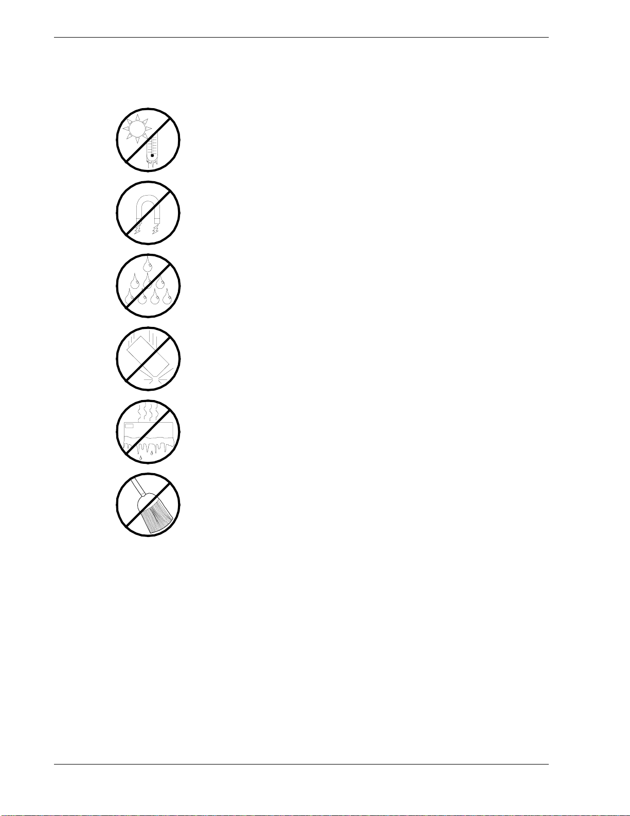
Care and Handling
Use the following guidelines to properly handle and care for your system.
Protect the system from extremely low or high temperatures. Let
the system warm (or cool) to room temperature before using it.
Keep the system away from magnetic forces.
Keep the system dry. Do not wash the system with a wet cloth or
pour fluid into it.
Protect the system from being bumped or dropped.
Check the system for condensation. If condensation exists, allow it
to evaporate before powering on the system.
Keep the system away from dust, sand, and dirt.
xiv Using This Guide
Page 17

System Overview
! Overview
! System Features
! System Chassis Features
! Standard Features
! Power Supplies
! Peripheral Bays
! System Functions
! Security
1
Page 18
Overview
Your server is a modular, multiprocessing server based on the Intel® Xeon
microprocessor family. It is a solid performer and offers the latest technology. The
combination of compute performance, memory capacity, and integrated I/O provides a
high performance environment for many server market applications. These range from
large corporations supporting remote offices to small companies looking to obtain basic
connectivity capability such a file and print services, e-mail, web access, web site
server, etc.
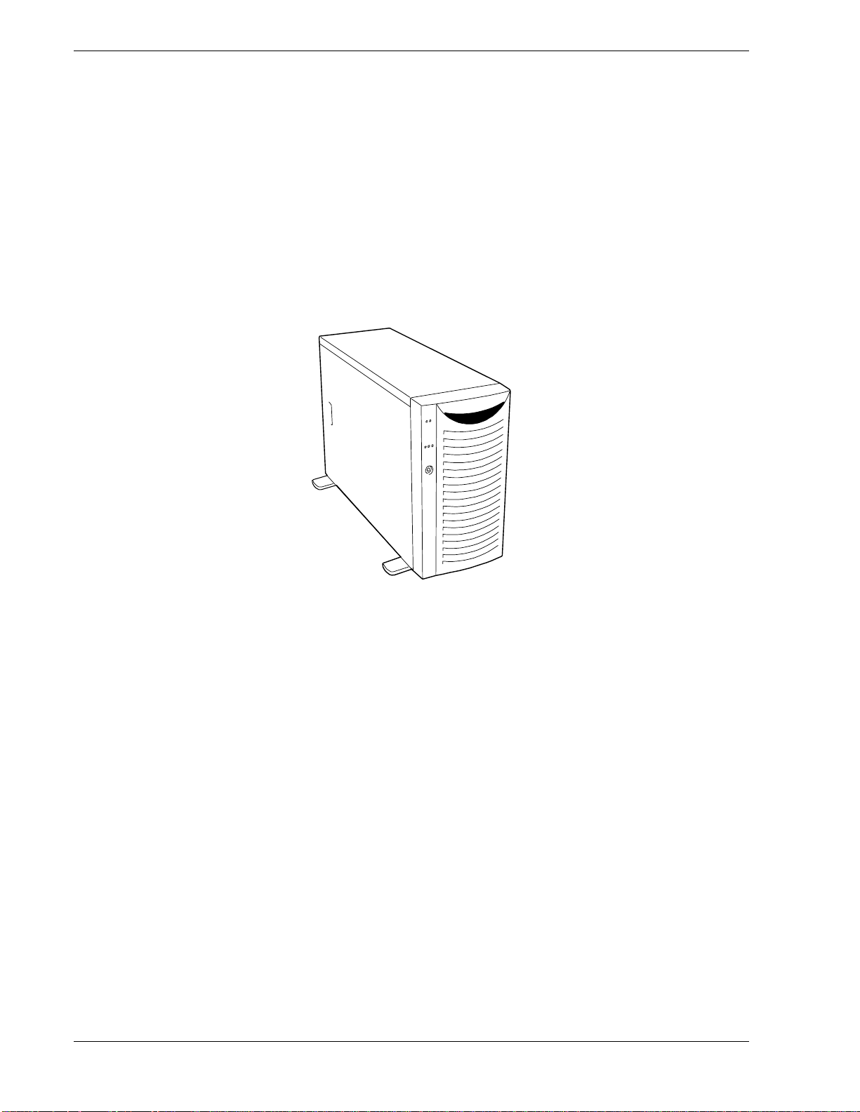
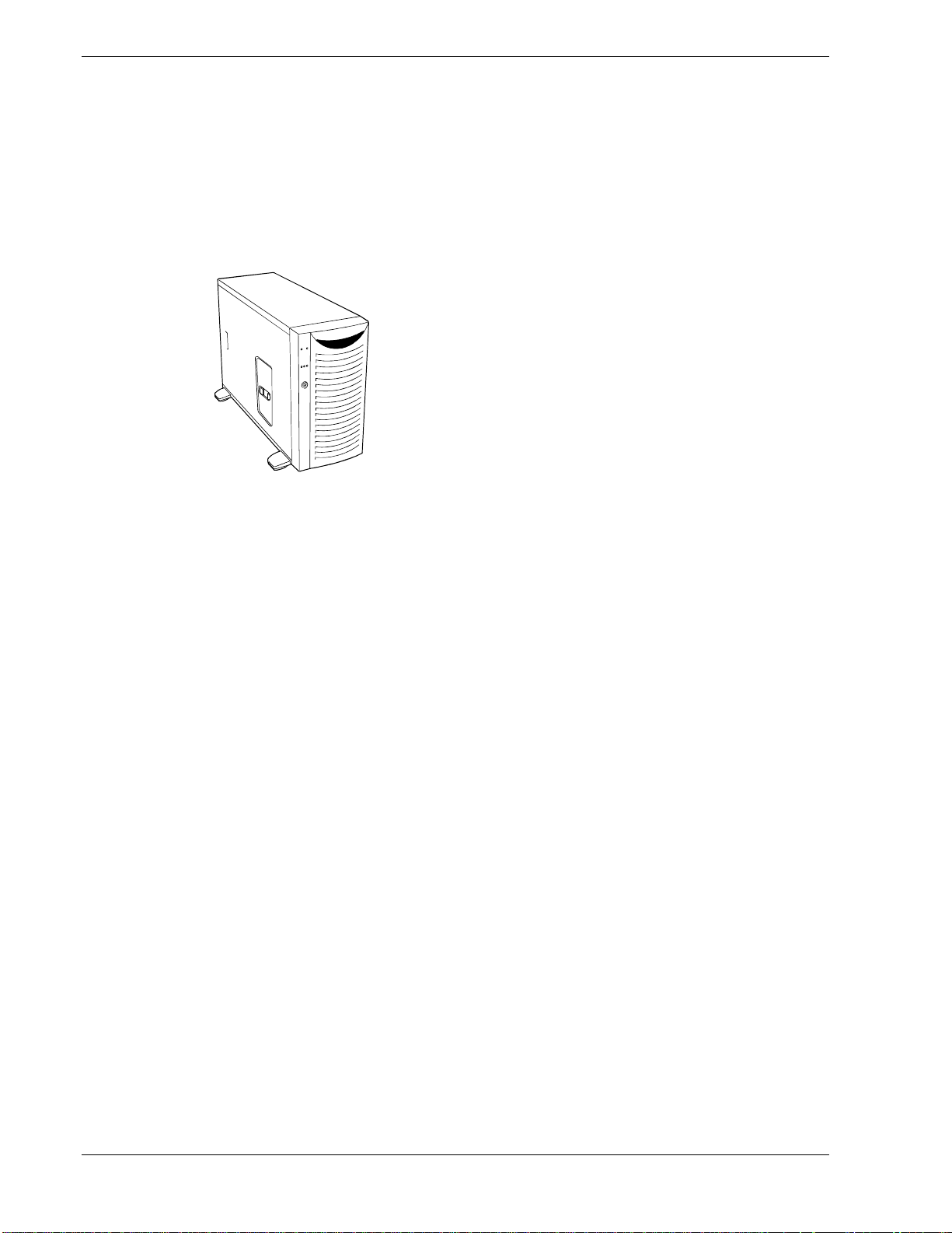
This server is conveniently housed and available as a tower-based system
(see Figure 1-1) or as a rack-mount system (fits into a standard EIA 19-inch rack
assembly).
Figure 1-1 Tower System Front View
Your server may include hot-swap SCSI hard disk drive bays. The hot-swap SCSI hard
disk drive bays hold up to six 1.0-inch SCSI hard disk drives that can be swapped in or
out of the system without powering it down, if RAID is configured in the system.
As application requirements increase, you can expand your server with an additional
processor, additional memory, add-in boards and peripheral devices; tape devices, CDROM, and hard disk drives.
1-2 System Overview
Page 19

System Features
Your system features the following major components:
! Single or dual high-performance Intel™ Xeon™ 1.80GHz or 2.66GHz
processors.
! 256 MB to 4 GB of ECC SDRAM two way interleaved memory, using up to four
DIMMs.
! Six PCI expansion slots for add-in boards (four 64-bit/100MHz PCI slots and
two 32-bit/33MHz PCI slots).
! A maximum of six hot-swap SCSI hard disk drive bays accessible from the front
of the chassis.
! Hot-swap SCSI disk drive backplane; a failed drive can be removed and replaced
with a new drive without system power being turned off (if an optional
Redundant Array of Independent Disks (RAID) controller is installed.)
! High degree of SCSI disk fault tolerance and advanced disk array management
features through the use of RAID technology, if an optional RAID controller is
installed.
! Embedded PC-compatible support (serial, parallel, mouse, keyboard, diskette,
USB, LAN, and video).
! Integrated onboard ATI RAGE XL Video Graphics Array (VGA) controller with
8MB of video memory (VRAM).
! Adaptec SCSI controller providing Ultra-320/160 SCSI interfaces.
! Integrated Network Interface Controller (NIC), a dual channel Gigabit Ethernet
LAN controller supporting 10Base-T/100Base-TX/1000Base-T network systems.
! Dual channel enhanced IDE controller.
! Four slot, 5.25-inch removable media device bay.
! IDE CD-ROM drive and 3 ½-inch diskette drive.
! Three integrated Universal Serial Bus (USB) ports, one located at the front panel
and two located at the rear panel.
! Hardware monitors (temperature, fans, and voltage) and software monitors to
indicate failures.
! Chassis that supports up to two power supply modules. The additional power
supply is needed to provide hot-swappable redundant power (i.e., the system will
continue to operate with a single power supply failure). With two power modules
installed, one power module can be easily removed or installed from the back of
the chassis without turning the system power off.
! Fully lockable front bezel including Server Management software that monitors
the front bezel intrusion switch.
System Overview 1-3
Page 20
System Chassis Features
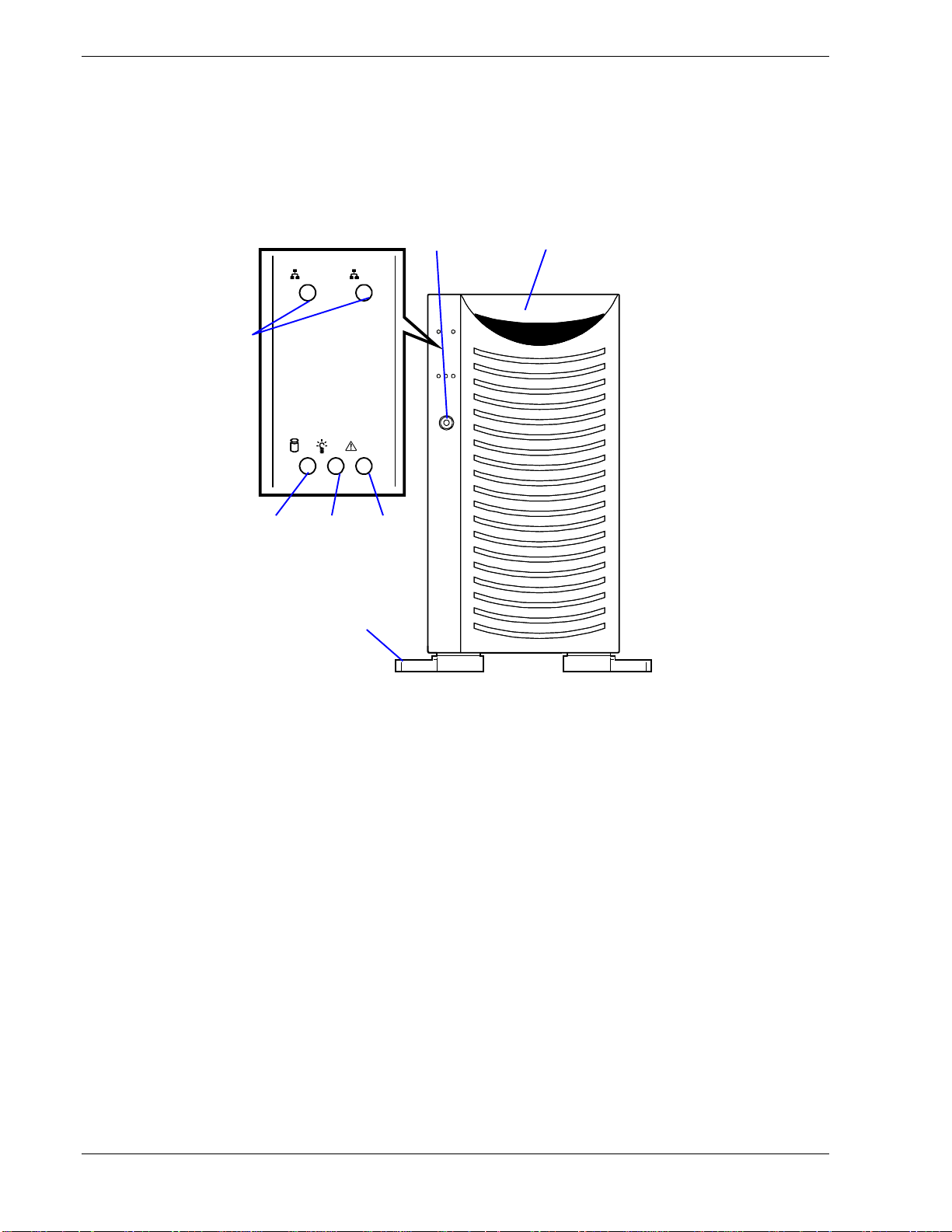
Figure 1-2 shows the system front view features seen with the front door closed.
Front View
4
5 6 7
1 2
3
2
1
1 Front door
Open this door to access the POWER switch, 5.25-inch devices, the CD-ROM drive, or the
floppy disk drive, or to install/remove hard disks to 3.5-inch bays. You can lock the front door
using the provided security key.
2 Key lock
When locked, secures the front door not allowing access to the front system controls.
3 Stabilizers (4)
Use the stabilizers to prevent the server from falling down.
4 LAN ACCESS lamp (green)
Lights in green while the server is connected to the network. Blinking in green indicates the
network activity. Numbers printed near the lamps indicate the LAN port number.
5 DISK ACCESS lamp (green/amber)
Lights in green while the internal hard disk is in access. When any one of the internal hard
disks fails, this lamp lights in amber.
6 POWER/SLEEP lamp (green)
Lights in green when the server is powered on. Off when the server is powered off. Blinks
when the system is placed in the sleep mode.
7 STATUS lamp (green/amber)
Lights in green while the server is in successful operation. When any error is detected, this
lamp lights in amber.
1-4 System Overview
Figure 1-2. Front View (Door closed)
Page 21
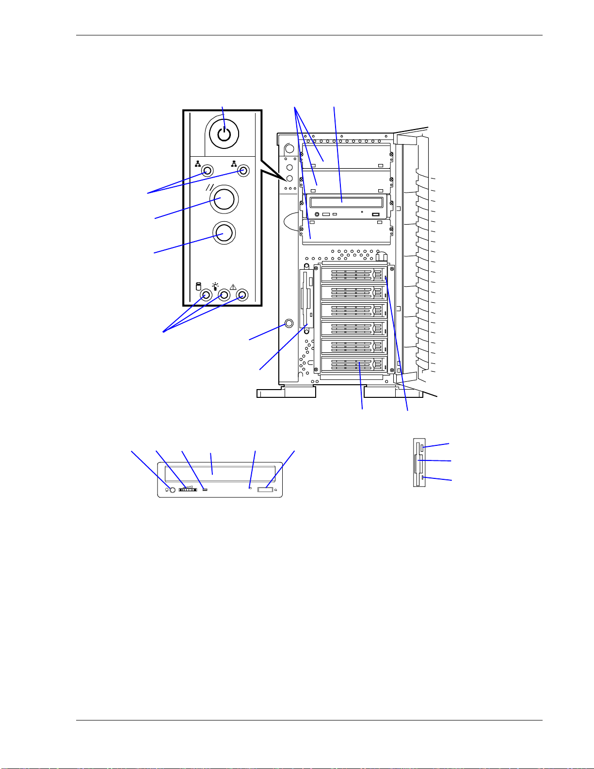
Front View (Door Opened)
Figure 1-3 shows the system front view features seen with the front door opened.
1 2
8
9
10
1 27
8
2-1 2-2 2-3 2-4 2-5 2-6
6
5
CD-ROM Drive Floppy Disk Drive
Figure 1-3. Front View (Door opened)
4 3
5-1
5-2
5-3
System Overview 1-5
Page 22

1 5.25-inch device bay
Backup tape drives may be installed in the 5.25-inch device bay.
2 CD-ROM drive
The CD-ROM drive reads data from the inserted CD-ROM.
2-1 Headphone jack
2-2 Volume control
2-3 Access lamp (lights in amber while being accessed)
2-4 CD-ROM slot
2-5 Emergency hole
2-6 Open/Close button
3 Disk lamp (green/amber)
The disk lamp is lit green if a hard disk installed in the server is accessed. If a hard disk is
defected, the lamp is lit amber. During the rebuild processing, the lamp is lit green or amber
alternately. (This occurs only in the disk array configuration.)
4 3.5-inch hard disk drive bay
The 3.5-inch hard disk drive bay contains up to six hard disks. Hard disks having the
thickness of 1 inch can be inserted into the slots.
The SCSI IDs are defined as follows:
ID0 to ID5 from bottom to top.
5 3.5-inch floppy disk drive
Insert a 3.5-inch floppy disk to the 3.5-inch floppy disk drive to read data from the disk or write
data to the disk.
5-1: Eject button
5-2: Disk inserting section
5-3: Floppy disk access lamp (lit green during accessing)
6 Cover open sensor
The cover open sensor detects the open of the front door.
7 Power switch
The power switch is used to turn on/off the power. If you press the switch once, then the
POWER/SLEEP lamp goes on and the power is turned on. If you press the switch again, the
power is turned off. The system is forcibly shut down when the power switch is pressed
continuously for four seconds or longer.
8Lamps (see the figure on the prev ious page)
9 Reset switch
The reset switch is used to reset the server.
10 Dump switch (NMI switch)
Non-maskable Interrupt switch.
The dump switch is used to collect the event logs having occurred in the server.
Figure 1-3. Front View (Door opened)
1-6 System Overview
Page 23
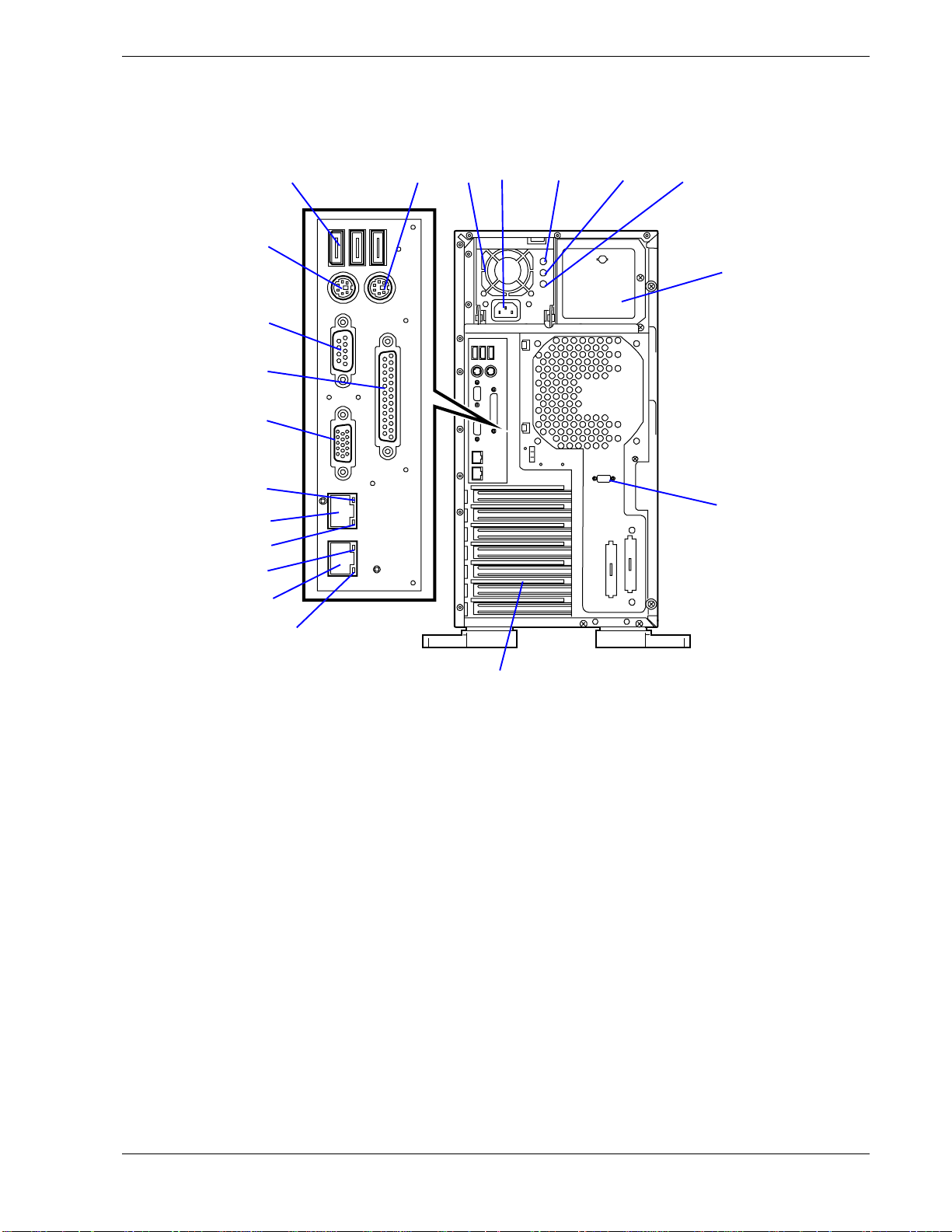
Rear View
Figure 1-4 shows the system rear view features.
11
12
13
14
1
910
2 3 4 5
6
15
16-1
17-1
15
16-2
7
17-2
8
System Overview 1-7
Page 24

1 Power supply
The power unit supplies DC powers to the server.
2 AC inlet
The AC inlet is connected with the power cord.
3 DC power lamp
The AC power lamp blinks green if the power supply receives the AC power through the power
cord. The lamp goes on green when the power of the server is turned on.
4 Power status lamp
The lamp goes on if the power is defected.
5 AC power lamp
If the power cord is plugged to the AC inlet to supply AC power to the power supply unit, this
lamp goes on.
6 Additional power supply slot
An optional power supply may be installed on the slot.
7 Serial port B connector
The serial port B connector is used to connect the server to a device with the serial interface.
The server cannot be directly connected to a leased line through the connector.
8 Additional PCI board slots
Optional PCI boards may be inserted into the slots.
9 Mouse connector
The mouse connector is connected with the mouse coming with the server.
10 USB-1 - USB-3 connectors
The USB-1 to USB-3 connectors are connected with devices accepting the USB interface.
Connector 1 to connector 3 are assigned from right to left.
11 Keyboard connector
The keyboard connector is connected with keyboard coming with the server.
12 Serial port A connector
The serial port A connector is connected with a device having the serial interface.
13 Printer port connector
The printer port connector is connected with a printer with the Centronics interface.
14 Monitor connector
The monitor connector is connected with the display unit.
15 Link/ACT lamp
The Link/ACT lamp shows the LAN access status.
16 LAN connector
The LAN connector is connected with a network system on LAN. The value following the boldfaced number indicates the port number.
16-1 LAN2 supports 1000BASE-T/100BASE-TX/10BASE-T network subsystem.
16-2 LAN1 supports 100BASE-TX/10BASE-T network subsystem.
17 Speed lamp
Indicates the LAN transfer rate.
17-1 1000/100/10 lamp
17-2 100/10 lamp
Figure 1-4. Rear View
1-8 System Overview
Page 25
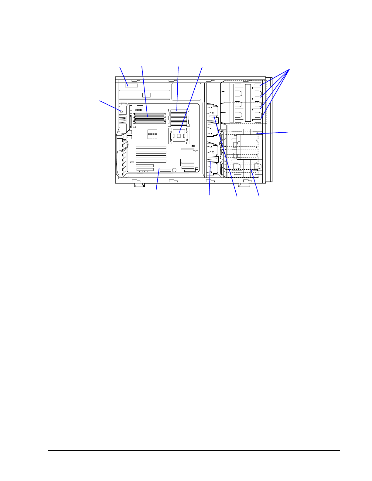
Internal View
Figure 1-5 shows an internal view of your system with the air duct covers removed.
12 3 4
11
10
1 Power supply
2 DIMMs (factory-instal led in slots #1A and #1B.)
3
4CPU2
5 5.25-inch device bays (4 slots)
6 3.5-inch floppy disk drive
7 3.5-inch hard disk drive bay
8 Cooling fan (Fan 5: option)
9 Cooling fan (Fan 3: option)
10 Mother board
11 Cooling fan (Fan 1)
(factory-installed)
CPU1
A standard CD-ROM drive is installed in slot #3. The device bay can include a maximum of
two optional file devices.
The hard disk drive bay can hold up to six 1.0-inch SCSI hard disk drives.
789
5
6
Figure 1-5. Internal View
System Overview 1-9
Page 26
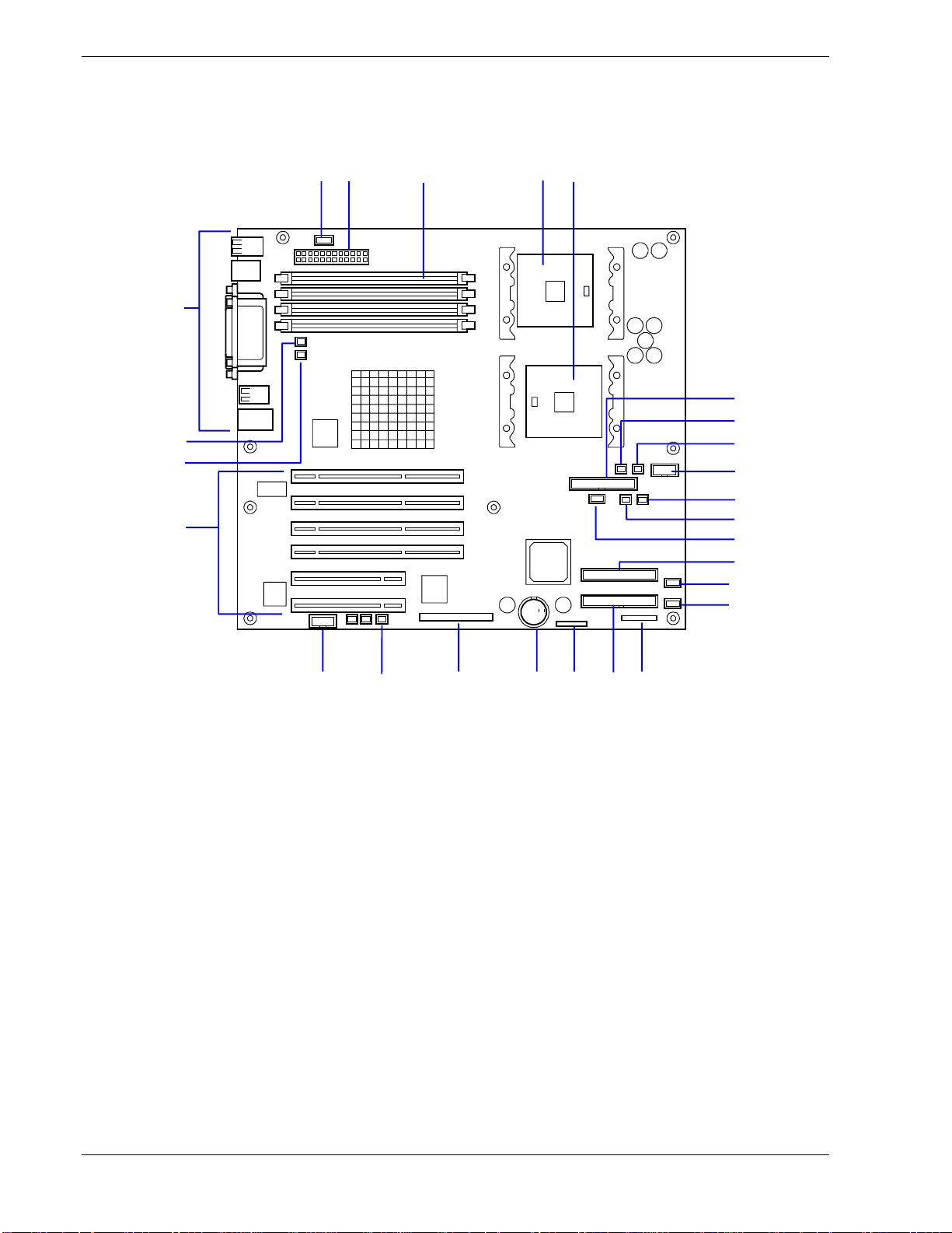
System Board Features
Figure 1-6 shows details of the system board.
26
25
24
23
1 2 3 4 5
10
11
12
13
14
15
6
7
8
9
2122
1617181920
1-10 System Overview
Page 27

1
Power signal connector
2
Power connector
3
DIMM sockets (slots #1A, #1B, #2A, and #2B from top to bottom)
4
CPU1 socket
5
CPU2 socket
6
Floppy disk drive connector
7
Cooling fan connector (Fan 5)
8
Cooling fan connector (not used)
9
Power connector
10
HSBP (B) connector (not used)
11
HSBP (A) connector (not used)
12
USB connector
13
IDE connector (for CD-ROM drive)
14
Cooling fan connector (not used)
15
Cooling fan connector (Fan 3: option)
16
Front panel interface connector
17
IDE connector (not used)
18
Jumper switch for clearing CMOS/p assword
19
Lithium battery
20
Ultra320 (A) connector (for built-in hard disk)
21
DAC LED connector
22
Serial (COM B) connector
23
PCI board slots
(slots PCI #1, PCI #2, PCI #3, PCI #4, PCI #5, and PCI #6 arranged from top to bottom)
PCI #1 to #4: 64-bit/100 MHz
PCI #5, #6: 32-bit/33 MHz
24
Cooling fan connector (Fan 1)
25
Cooling fan connector (Fan 2: option)
26
External connection connector
Figure 1-6. System Board
System Overview 1-11
Page 28
Standard Features
High performance Expandability
! Intel Xeon Processor
N8100-865F: 1.8GHz
N8100-866F: 2.66GHz
! High-speed 1000BASE-T/100BASE-TX/
10BASE-T interface
(1000Mbps/100Mbps/10Mbps supported)
! High-speed disk access
(Ultra320 SCSI)
High-reliability Many Available Features
! Memory monitoring feature (single-bit
error correction/double-bit error detection)
! CPU/memory/cooling fan degradation
feature (logical isolation of a failed device)
! Bus parity error detection
! Temperature detection
! Error notification
! Internal CPU fan monitoring feature
! Internal voltage monitoring feature
! BIOS password feature
! Security feature (security lock)
! Redundant power supplies (1+1)
! Wide variety of optional I/O slots
Four 64-bit, 100 MHz PCI slots
Two 32-bit, 33 MHz PCI slots
! Large memory of up to 4 GB
! Six SCSI hard disk drive bays (hot-
swappable)
! Remote power-on feature
! Up to two Intel Xeon processors
! Two power supplies (Redundancy)
! USB interface (A USB-support driver is
required.)
! Convert to rack-mount type (N8143-56F
Rack Conversion Kit is required.)
! Graphic accelerator "RAGE XL" support
! El Torito Bootable CD-ROM (no emulation
mode) format support
! POWER switch mask
! Software power-off
! Remote power-on feature
! AC-LINK feature
! Intelligent Platform Management Interface
(IPMI)
! Baseboard Management Controller (BMC)
! Remote console feature
Self-diagnosis
! Power On Self-Test (POST)
! Test and Diagnosis
Management Utilities Maintenance Features
! ESMPRO
! Management Workstation Application
( MWA)
Power Saving Feature Easy and Fine Setup
! Sleep feature
(available for Windows 2000)
1-12 System Overview
! Off-line Maintenance Utility
! Memory dump feature using the DUMP
(NMI) switch
! EXPRESSBUILDER (system setup utility)
! SETUP (BIOS setup utility)
! SCSISelect (SCSI device utility)
! Configuration Diskette Creator
Page 29

Xeon™ Processors
Depending on system configuration, each system includes one or two Intel Xeon
1.80GHz or 2.66GHz processors. Each processor plugs into a INT3/FCPGA socket
package. The processor includes a 512K cache. When two processors are installed, both
processors must be of identical bus and core speed.
The processor external interface operates at a maximum of 400MHz. The second-level
cache is located on the substrate of the processor cartridge. The cache includes burst
pipelined synchronous static RAM (BSRAM).
System Memory
The system board contains four 168-pin DIMM sockets. Memory is partitioned as two
banks of registered SDRAM DIMMs (DDR200 compatible) that must be populated in
pairs, each providing 72 bits of buffered two-way interleaved memory (64-bit main
memory plus ECC). Your system may include from 256 MB to 4 GB of memory, using
up to four DIMMs.
System memory begins at address 0 and is continuous (flat addressing) up to the
maximum amount of DRAM installed (exception: system memory is noncontiguous in
the ranges defined as memory holes using configuration registers). The system
supports both base (conventional) and extended memory.
PCI Riser Slots
The server's expansion capabilities meet the needs of file and application servers for
high performance I/O by providing PCI expansion slots.
The system board has four full-length, full height 64-bit/100MHz PCI slots and two 32bit/33MHz PCI slots.
Video Controller
The system board uses an ATI RAGE XL PCI graphics accelerator with 8 MB of video
SDRAM. The embedded SVGA video subsystem supports:
! Resolutions up to 1600 x 1200 under 2D and 1024 x 768 under 3D
! CRT and LCD monitors up to 100 Hz vertical refresh rate.
The system board supports disabling of the onboard video through the BIOS setup
menu or when a plug in video card is installed in any of the PCI slots.
SCSI Controller
The system board includes an embedded Adaptec AIC7901W SCSI controller. The
AIC7901W provides Ultra-320/160 SCSI functions. As implemented on the system
board, the interface attaches to an Ultra-320/160 SCSI backplane that supports up to six
Ultra-320/160 SCA drives.
Network Controller
The system board uses a dual-channel Ethernet Controller and supports 10BaseT/100Base-TX/1000Base-T network subsystems.
System Overview 1-13
Page 30
The Network controller supports the following features:
! 64-bit, 100 MHz PCI-X interface
! Integrated IEEE 802.3 10Base-T, 100Base-TX, and 1000Base-T compatible
PHY
! IEEE 820.3u auto-negotiation support
! Chained memory structure similar to the 82557, 82558, 82559 and 82596
! Full duplex support at 10 Mbps, 100 Mbps, and 1000 Mbps operation
! Low power +3.3 V devices.
On the system board, NIC1 can be used as both a network interface and server
management interface.
Keyboard and Mouse
The keyboard/mouse controller is PS/2-compatible.
RJ-45 Serial Port
The rear RJ-45 serial port is a fully functional serial port that supports any standard
serial device and provides support for serial concentrators. For server applications that
use a serial concentrator to access the server management features of the mother board,
a standard 8-pin CAT-5 cable from the serial concentrator is plugged directly into the
rear RJ-45 serial port. The 8 pins of the RJ-45 connector can be configured to match
either of two pin-out standards used by serial port devices.
ACPI
To accommodate either standard, the J5A2 jumper block located directly behind the
rear RJ-45 serial port must be jumpered appropriately according to the desired standard.
An Advanced Configuration and Power Interface (ACPI) aware operating system can
place the system into a state where the hard drives spin down, the system fans stop, and
all processing is halted. However, in this state the power supply is still on and the
processors are still dissipating some power such that the power supply fan and
processor fans are still running.
Note: ACPI requires an operating system that supports its
feature.
!
CAUTION
Only when the AC power is disconnected is the system completely
off.
The sleep states are defined as follows:
! s0: Normal running state.
1-14 System Overview
Page 31

! s1: Processor sleep state.
No context will be lost in this state and the processor caches will maintain
coherency.
! s4: Hibernate or Save to Disk.
The memory and machine state are saved to disk. Pressing the power button or
other wakeup event restores the system state from the disk and resumes normal
operation. This assumes that no hardware changes have been made to the system
while it was off.
! s5: Soft off.
Only the RTC section of the chipset and the BMC are running in this state.
System Board Management Controller (BMC)
Server management is concentrated in the System Board Management Controller
(BMC). The BMC and associated circuitry are powered from a 5Vdc standby voltage,
which remains active when system power is switched off, but the ac power source is
still on and connected.
The BMC supports the Management Workstation Application (MWA), which allows
remote server management via a modem or direct connection to a manager system.
Events monitored by the manager system include over-temperature and over-voltage
conditions, fan failure, or chassis intrusion.
Information on the Management Workstation Application (MWA) may be found in
Appendix B of this User’s Guide.
One major function of the BMC is to autonomously monitor system management
events, and log their occurrence in the nonvolatile System Event Log (SEL). The events
being monitored include overtemperature and overvoltage conditions, fan failure, or
chassis intrusion. To enable accurate monitoring, the BMC maintains the nonvolatile
Sensor Data Records (SDRs), from which sensor information can be retrieved. The
BMC provides an ISA host interface to SDR sensor information, so that software
running on the server can poll and retrieve the server's current status.
The BMC performs the following:
! Monitors server board temperature and voltage
! Monitors processor presence and controls Fault Resilient Boot (FRB)
! Detects and indicates baseboard fan failure
! Manages the SEL interface
! Manages the SDR Repository interface
! Monitors the SDR/SEL timestamp clock
! Monitors the system management watchdog timer
! Monitors the periodic SMI timer
! Monitors the event receiver
System Overview 1-15
Page 32

! Controls secure mode, including video blanking, diskette write-protect
monitoring, and front panel lock/unlock initiation
! Controls Wake On LAN via Magic Packet support.
Power Supplies
The system contains one auto-sensing 450-watt power supply at an operating frequency
of 50/60 Hz.
A second optional power supply may be added as part of a fault-tolerant hot-swap
design. With two power supplies installed, in the unlikely event of a power supply
failure, the load is transferred to the remaining power supply without interruption to
normal operation. In this case the faulty power supply can be replaced without
powering down the system.
NOTE: The power supplies are not hot-swappable unless there are two power
supplies installed.
The power supplies are designed to comply with existing emission standards and
provide sufficient power for a fully loaded system configuration.
Peripheral Bays
The system supports a variety of standard PC AT-compatible peripheral devices. The
chassis includes these peripheral bays:
! A 3.5-inch front panel bay for installing the standard 3.5-inch floppy disk drive
(supports 720KB and 1.44MB floppy disk media)
! Four 5.25-inch device bays for installing half-height or full-height 5.25-inch
peripheral devices such as an optional tape drives.
! The SCSI hard disk drive bays for installing up to six SCSI hard disk drives.
The SCSI disk drives can be easily installed or removed. The drive carrier allows you
to access to disk drives from the front of the system. If disk drives are provided with
RAID configuration within the system, a disk drive can be swapped with another
without power interruption in the system (hot-swap).
NOTE:
require an 80-pin single connector attachment (SCA) connector on the drives that
you install.
The SCSI hard disk drive bays contain a hot-swap back plane that
1-16 System Overview
Page 33

System Functions
The following subsections describe select system functions.
Degradation Feature
The degradation feature automatically isolates a failed DIMM or processor to assure
continuous operation of the server when the POST (Power On Self-Test, self-diagnosis
program after power on) detects such a DIMM or processor.
Failed DIMMs and processors may be identified on the screen that the POST displays,
or with the BIOS setup utility, "SETUP." They may also be identified on the system
that has the ESMPRO installed.
Remote Power-On Feature (Wake On LAN)
The remote power-on function turns on the server through a network. It sends a special
packet from the management computer to a remote server to turn it on if the server is
off-powered.
To enable this feature, you must select "Enabled" for "Wake on LAN" in the Advanced
Chipset Control of the Advanced menu of the BIOS setup utility, "SETUP." (See
Chapter 4.)
The remote power-on feature is not available in the following cases. Press the POWER
switch once to start the OS, and turn off the server in an appropriate procedure.
! Abnormal previous system shut-down
! No power supply to the server (due to turned-off breaker, disconnected power
cord, power blackout, etc.)
AC-LINK Feature
When the power cord of the server is connected to an uninterruptible power supply
(UPS) unit, the server supports the power linkage feature that enables control over the
power supply from the UPS to the server. The AC-LINK feature can be enabled or
disabled with the Server menu of the BIOS setup utility, "SETUP." (See Chapter 4.)
System Overview 1-17
Page 34

Security
To help prevent unauthorized entry or use of the system, the system includes a full
lockable front panel and Server Management software that monitors the system
intrusion switches.
Security with Mechanical Locks and Monitoring
The front door of the server contains a mechanical lock to prevent access to the front of
the computer chassis.
The computer chassis includes an intrusion switch for the front cover and
intrusion/interlock switches for the left side cover (as viewed from the front). When
any these covers are opened, the switch transmits an alarm signal to the system board,
where server management software processes the signal. The side cover switch also
operates as interlock switch.
Software Locks via the System Setup Utility
The BIOS SETUP Utility provides a number of security features to prevent
unauthorized or accidental access to the system. Once the security measures are
enabled, access to the system is allowed only after the user enters the correct
password(s). For example:
! Enable the keyboard lockout timer so that the server requires a password to
reactivate the keyboard and mouse after a specified time-out period – 2 to 120
minutes.
! Set and enable an administrative password.
! Set and enable a user password
! Set secure mode to prevent keyboard or mouse input and to prevent use of the
front panel reset and power switches.
! Activate a hot-key combination to enter secure mode quickly.
! Disable writing to the floppy disk drive when secure mode is set.
1-18 System Overview
Page 35

Setting Up the System
! Overview
! Selecting a Site
! Unpacking the System
! Making Connections
! Connecting the Power Cord
! Using the System
2
Page 36

Overview
This chapter describes how to select a site, unpack the system, make cable
connections, and power on the system units. Information on front and rear panel
features, switches and LEDs are also included in this chapter.
Selecting a Site
The system operates reliably in a typical office environment.
Choose a site that is:
! Near grounded, three-pronged power outlets.
Note: For the United States and Canada, this means a
NEMA 5-15R outlets for 100-120 VAC or NEMA 6-15R
outlets for 200-240 VAC. For other international sites, this
means three-pronged power outlets applicable for the
electrical code of the region.
Be sure the power service connection is through a properly
grounded outlet.
!
WARNING
!
CAUTION
When two power supplies are installed in the system the
power plug from each of the power supplies must be
plugged into the same common ground power outlets.
! Clean, dust-free, and well ventilated. Front and rear ventilating openings
kept free of obstructions. Away from sources of heat, vibration or
physical shock.
! Isolated from strong electromagnetic fields and electrical noise produced
by electrical devices (such as air conditioners, large fans, large electric
motors, radio and TV transmitters, and high-frequency security devices)
! Spacious enough to provide at least ten inches (25 centimeters) in front of
the system, five inches (13 centimeters) behind the system and three
inches (eight centimeters) on each side of the system for proper cooling,
airflow, and cable clearance.
! Easily accessible for system maintenance and installation of system
upgrades.
2-2 Setting Up the System
Page 37

Unpacking the System
!
WARNING
The non-hot-swap system can weigh up to 40 pounds
(18 kg) and the hot-swap system can weigh up to 77 pounds
(35 kg). If the system contains numerous optional boards
and peripheral devices, it will weigh more. To avoid personal
injury, make sure you have someone help you lift or move
the system.
When you receive your system, inspect the shipping containers prior to
unpacking. If the shipping boxes are damaged, note the damage, and if possible,
photograph it for reference. After removing the contents of the containers, keep
the cartons and the packing materials. If the contents appear damaged when you
unpack the boxes, file a damage claim with the carrier immediately.
Making Connections
If your system normally operates without a video display or keyboard (for
example, as a network server), you must install a video display and keyboard to
configure the system. You may remove them after running the BIOS Setup
Utility. For information on running the BIOS Setup Utility, refer to Chapter 3
"Configuring Your System" of this User’s Guide.
Refer to the previous figure (Rear Features and Controls) and connect your
keyboard, monitor, and mouse. Connect any external peripheral devices such as
a printer or modem by following the instructions included with these devices.
!
CAUTION
Damage to the system may result if the keyboard/mouse
cable is inserted or removed when power is applied to the
system.
Inserting a telephone line connector into a RJ-45 LAN port
may result in personal injury and equipment damage.
The server is provided with connectors for wide variety of peripheral devices on
its front and rear. Figure 2-1 illustrates available peripheral devices for the
server in the standard configuration and locations of the connectors for the
devices.
!
CAUTION
Power off the server and peripheral device before
connection. Connecting a powered peripheral device to the
powered server may cause malfunctions and failures.
Setting Up the System 2-3
Page 38

! Before connecting a third-party peripheral device or interface cable to the
server, consult with your sales agent. Some third-party devices may not
be used with the server.
! The total length of a cable (including the connection cable within a SCSI
device) is limited by the SCSI standard. Ask your service representative
for details. (The internal SCSI cable of the server is 0.1 m long.)
! The LAN connector and the serial port 2 connector of this server have the
same shape. Be careful not to connect a cable to the wrong connector.
Tag all LAN and serial port cables.
A leased line cannot be connected directly to the serial port connectors.
Device with the USB interface
(e.g., terminal adapter)
Keyboard
Device with the serial interface (e.g.,
modem)
Direct connection to
the private telephone
line is prohibited.
Display unit
Hub
(multiport repeater)
Connect appropriat e
Mouse
power source.
3
Printer with the
parallel interface
2-4 Setting Up the System
REAR
Device with the serial interface (e. g., modem )
Direct connection to the private telephone line
is prohibited.
Figure 2-1. Making Connections
Page 39

Connecting the Power Cord
Plug the female end of each AC power cord shipped with your system into the
input receptacle on the rear of each power supply shipped with your system.
Plug the male end of the power cord into NEMA 5-15R outlet for 100-120 VAC
or NEMA 6-15R outlet for 200-240 VAC.
If a power cord supplied with the system is not compatible with the AC wall
outlet in your region, obtain a suitable power cord that meets the following
criteria.
! The power cord must be rated for the available AC voltage and have a
current rating that is at least 125% of the current rating of the system.
! The power cord connector that plugs into the wall outlet must be
terminated in a grounding-type male plug designed for use in your region.
It must have certification marks showing certification by an agency
acceptable in your region.
! The power cord connector that plugs into the system must be an
IEC- type CEE-22 female connector.
! The power cord must be less than 1.8 meters (6.0 feet) long.
When connecting the power cord to a power control unit such as an UPS unit,
confirm that the power control unit is powered OFF. Connecting the power cord
while power is supplied to the power control unit may cause a failure.
A power cord is provided for each power supply shipped with
your system. Do not attempt to modify or use the supplied
AC power cord if it is not the exact type required.
Using the System
The following subsections describe how to use this server system properly and
safely, including an explanation of the server system power on/off sequences,
what the POST program checks in the server, and how to perform a forced
power shutdown.
When using the server system the following precautions should be observed.
! Do not delete the hard disk partition exclusively provided for
maintenance of the server although it may appear on the operating system
(OS). Deleting the hard disk partition may cause malfunction of the
server.
! Make sure you power off the server before connecting or disconnecting
cables between the server and peripheral devices. Connecting or
disconnecting the cables while the server is powered on may cause
malfunction or failures within the server.
!
WARNING
Setting Up the System 2-5
Page 40

! Verify that the access lamp on the diskette drive is unlit before turning off
the server or ejecting the floppy disk. Turning off the server or ejecting
the floppy disk while the access lamp is lit may damage data being stored
on the floppy disk.
! After turning off the server, wait at least 40 seconds before turning it on
again. Cycling the power immediately may cause malfunction or failures
of the server.
! Before relocating the server, turn off the power and unplug the power
cord from the outlet. Moving the server when it is powered may cause
malfunction or failures of the server.
! Some software includes a command to eject the CD-ROM tray or a media
in a device mounted in the 5.25-inch device bay. Make sure that the front
door of the tower-based cabinet is open before running the command.
Running this command with the front door closed may cause the CDROM tray or the media to hit against the front door, resulting in a
possible failure of the CD-ROM.
! Clean the server regularly. Regular cleaning prevents failures of the
server and its components.
! Lightning may cause a momentary voltage drop. To prevent this problem,
an uninterruptible power supply unit is recommended.
! Only use options qualified for the server. A non-qualified option may be
mounted or connected to the server, but it may fail to operate normally or
even cause failures. These types of failures are not covered under
warranty.
Opening the Front Door of the Tower Cabinet
You must open the front door of the tower cabinet to turn the server power on or
off, place the server in sleep mode, mount or dismount a floppy disk, mount or
dismount a hard disk drive, or mount or dismount 5 1/4-inch removable media
devices.
Note: The standard CD-ROM drive and some options for
the 5 1/4-inch devices such as a CD-ROM drive have a
function to eject a tray or media using a software command.
Before issuing a software command to eject a tray or media,
confirm that the front door is open. If the command is
executed while the front door is closed a tray or media may
run into the front door resulting in an error or may cause the
unit to fail.
2-6 Setting Up the System
Page 41

Powering On Your System
Power on your system as follows.
1. Make sure all external devices, such as a video display, keyboard, and
mouse (optional) have been connected, and the power cords are connected.
2. Power on the video display and any other external devices.
Note: If the server power cord(s) is connected to a
power control unit such as an UPS (Uninterruptible Power
Supply) make sure that the power control unit is powered on.
3. Open the front door (tower-based system only) and press the push-button
power on/off switch on the front panel. Verify that the system power-on
LED is lit. If it is not lit, ensure the ac power cord is connected to a
functional ac power source.
After a few seconds your system begins the internal Power-On Self Tests
(POST). POST automatically checks the system board, CPU(s), memory,
keyboard, mouse, and most installed peripheral devices. POST also displays the
start messages of the BIOS setup utility during execution.
The POST check results should be checked in the following cases:
! When the server is being used for the first time.
! When the server appears to fail.
! When the server beeps many times between power-on and OS start-up.
! When an error message appears on the display unit.
Note: For error messages that appear on the display
unit, refer to subsection POST Error Codes and Messages in
Chapter 5 of this Guide.
!
CAUTION
Always allow POST to complete before powering down your
system.
If you have problems powering on your system, refer to Problem Solving in
Chapter 5 of this User’s Guide.
After you have successfully powered on your system, insert the
EXPRESSBUILDER CD-ROM into the CD-ROM device, reboot the system
and follow the screen prompts to run EXPRESSBUILDER.
Setting Up the System 2-7
Page 42

Powering Off the Server System
When server system power is on, pressing the power on/off switch on the front
panel of the server turns the power off.
To turn the server system power off:
1. Shutdown the operating system (OS).
2. Press the power on/off switch on the front panel of the server. The power-on
LED goes out.
3. Power off the peripheral devices.
Note: If the server power cord is connected to a power
control unit such as an UPS (Uninterruptible Power Supply),
refer to the UPS user's guide for proper power-off
procedures.
Forcing a Power Shutdown
A forced power shutdown can be used when the power on/off switch does not
power off the server or the reset functions do not work.
To perform a forced power shutdown:
Press in on the power on/off switch located on the front panel of the
server for at least 4 seconds to force the server power off.
To power on after a forced shutdown, wait 10 seconds and then power on again.
2-8 Setting Up the System
Page 43

Configuring Your System
! Configuring Your System
! BIOS Setup Utility
! SCSISelect Utility
! Configuring the RAID Controller
! Configuring System Board Jumpers
3
Page 44

Configuring Your System
Configuration and setup utilities are used to change your system configuration.
You can configure your system, as well as option boards you may add to your
system, using the BIOS Setup Utility. Several unique system parameters are
configured using the BIOS Setup, which is stored in the system FLASH
memory.
The SCSISelect Utility detects the SCSI host adapters on the system board. Use
this utility if you need to configure the two SCSI controllers in your system or to
perform a SCSI disk format or verify disk operation on the SCSI disk drives.
The Adaptec Configuration Utility is also used to configure any SCSI
removable media devices installed in your system.
If your system has been factory configured, the BIOS Setup or SCSISelect
Utility do not need to be run unless you want to change the password or security
features, add certain types of option boards or devices, or upgrade your system
board.
This chapter also provides information on several system configuration
parameters that are set by jumpers on the system board. However, these
parameters do not usually require change.
Use the EXPRESSBUILDER CD-ROM to create the device driver diskettes.
3-2 Configuring Your System
Page 45

BIOS Setup Utility
The BIOS Setup Utility is used to change system configuration parameters. The
utility is resident in the system FLASH memory and does not require a diskette
or an operating system present to run.
Using the BIOS Setup Utility
You access the BIOS Setup utility when you turn on or reboot your system. To
run the BIOS Setup Utility, perform the following procedure:
1. Power-on or reboot the system. “Press <F2> to enter SETUP” displays.
2. Press F2. The BIOS Setup Utility starts and the Main Menu is displayed.
The menu bar at the top of the Main Menu lists the following selections:
Menu Use
Main Use this menu for basic system configuratio n.
Advanced Use this menu for setting the Advanced Features available on
your system.
Security Use this menu to set User and Supervisor Passwords and the
Backup and Virus-Check reminders.
Server Use this menu for configuring unique Server features.
Boot Use this menu to configure Boot Device priority.
Exit Exits the current menu.
Use the arrow keys to select a menu or an item on a displayed menu. Press
the value keys (listed in the table below) to cycle through the allowable
values for the selected field. Use the Exit menu’s “Save Values” selection to
save the current values on all the menus.
To display a submenu, position the cursor on a selection that has a submenu
and press ENTER. An arrow precedes selections with submenus.
Refer to the following table for information on the keys that you use with
BIOS Setup. These keys are also listed at the bottom of the Setup menu.
Configuring Your System 3-3
Page 46

Key Function in Setup Menu
F1 or Alt-H Get Help about an item.
ESC Exit the current menu and return to the previous menu.
Left or right arrow keys Move between menus.
Up or down arrow keys Move cursor up and down. The cursor moves only to the
settings that you can change.
HOME or END Move cursor to top or bottom of window.
PAGE UP or PAGE DOWN Move cursor to next or previous page.
F5 or - Select the previous value for the field.
F6 or + or SPACE Select the next value for the field.
F9 Load default configuration values for this menu.
F10 Save configuration values and exit.
ENTER Execute command or Select ➨ submenu.
BIOS Setup Configuration Settings
The BIOS Setup Configuration tables show the default settings for the BIOS
Setup Utility and provide a place for you to record any changes you make to
these settings. Recommended values are bold in the following tables.
3-4 Configuring Your System
Page 47

Main Menu
Choices or
Feature
System Time HH:MM:SS Set the System Time.
System Date MM/DD/YYYY Set the System Date.
Display Only Description Your Setting
Floppy A Disabled
1.44/1.25 Mb 3½”
720Kb 3.5”
2.88MB 3.5”
Floppy B
Hard Disk Pre-delay
Primary IDE Master Selects sub-menu
Primary IDE Slave Selects sub-menu
Secondary IDE
Master
Secondary IDE Slave Selects sub-menu
Disabled
1.44 / 1.25 Mb 3½”
720Kb 3.5”
2.88MB 3.5”
Disabled
3 seconds
6 seconds
9 seconds
12 seconds
15 seconds
21 seconds
30 seconds
Selects sub-menu
Hidden if not detected.
Hidden if not detected.
Allows additional time for
slower spin-up drives to come
ready.
Processor Settings
Language
Selects sub-menu
English (US)
French, German
Spanish, Italian
Selects which language BIOS
displays. Note: This feature
immediately changes to the
language BIOS selected.
Configuring Your System 3-5
Page 48

Primary and Secondary Master and Slave IDE Submenus
Choices or
Feature
Display Only Description Your Setting
Type
Multi-Sector Transfer
PI0 Mode Standard
Ultra DMA
Auto
None
Disabled
2 Sectors
4 Sectors
8 Sectors
16 Sectors
FPIO 1
FPIO 2
FPIO 3
FPIO 4
FPIO 3 / DMA 1
FPIO 4 / DMA 2
Mode 2
Processor Settings Submenu
Select Auto if a device is
attached to the IDE channel.
Specifies the number of
sectors that are transferred
per block during multiple
sector transfers. This field is
informational only, for Type
Auto.
Select the method for moving
data to/from the drive. This
field is informational only, for
Type Auto. This field is
updated to display only the
modes supported by the
attached device.
Selects the Ultra DMA mode
used for moving data to/from
the drive. This field is
informative only for Type
Auto.
Choices or
Feature
Processor POST
Speed Setting
Processor Retest
Hyper-Threading Disabled
Processor 1 CPUID
Processor 1 L2 Cache
Size
Processor 2 CPUID CPUID (OFXX)
Processor 2 L2 Cache
Size
Display Only Description Your Setting
Information Only Displays measured processor
Disabled
Enabled
Enabled
CPUID
Not Installed
Disabled
Information Only Displays L2 Cache Size for
Not Installed
Disabled
Information Only Displays L2 Cache Size for
speed.
If yes, BIOS will clear
historical processor status
and retest all processors on
the next boot. After retesting,
BIOS resets this option
automatically to “Disable”.
Specifies whether HyperThreading Technology is
enabled or disabled.
Reports CPUID for Processor
1, if present. If empty, reports
Vacant. If disabled by BMC,
reports Disabled.
Processor 1.
Reports CPUID for Processor
2, if present. If empty, reports
Vacant. If disabled by BMC,
reports Disabled.
Processor 2.
3-6 Configuring Your System
Page 49

Advanced Menu
Choices or
Feature
PCI Configuration Select sub-menu.
Peripheral Configuration Select sub-menu.
Memory Configuration Select sub-menu.
Advanced Chipset
Control
Boot-time Diagnostic
Screen
Reset Configuration
Data
Numlock On
Display Only
Select sub-menu.
Disabled
Enabled
No
Yes
Off
Description Your Setting
Specifies whether POST
messages are displayed.
If this item is set to "Disabled,"
the logo appears during POST.
The Boot-time Diagnostic
Screen is automatically enabled
if redirection is enabled.
Select ‘Yes’ if you want to clear
the System configuration Data
during next boot. Automatically
reset to ‘No’ in next boot.
Sets power on Numlock state.
Configuring Your System 3-7
Page 50

PCI Configuration Menu
Choices or
Feature
Display Only Description Your Setting
Onboard NIC 1
(10/100MB)
Onboard NIC 2
(1.0GB)
Onboard SCSI Select sub-menu.
Onboard Video Select sub-menu.
PCI Slot 1 ROM Disabled
PCI Slot 2 ROM Disabled
PCI Slot 3 ROM Disabled
PCI Slot 4 ROM Disabled
Select sub-menu.
Select sub-menu.
Enabled
Enabled
Enabled
Enabled
Used to enable or disable an
option ROM that may be
present on a PCI add-in card
connected to the full-height
riser card.
Used to enable or disable an
option ROM that may be
present on a PCI add-in card
connected to the full-height
riser card.
Used to enable or disable an
option ROM that may be
present on a PCI add-in card
connected to the full-height
riser card.
Used to enable or disable an
option ROM that may be
present on a PCI add-in card
connected to the low-profile
riser card.
PCI Slot 5 ROM Disabled
Enabled
PCI Slot 6 ROM Disabled
Enabled
Used to enable or disable an
option ROM that may be
present on a PCI add-in card
connected to the low-profile
riser card.
Used to enable or disable an
option ROM that may be
present on a PCI add-in card
connected to the low-profile
riser card.
3-8 Configuring Your System
Page 51

Onboard NIC 1 / Onboard NIC 2 Submenu
Choices or
Feature
Onboard NIC 1
Onboard NIC 2
Onboard NIC 1
ROM
Embedded NIC 2
ROM
Display Only
Enabled
Disabled
Enabled
Disabled
Enabled
Disabled
Enabled
Disabled
Onboard SCSI Submenu
Choices or
Feature
Onboard SCSI
Onboard SCSI
ROM
Display Only
Enabled
Disabled
Enabled
Disabled
Onboard Video Submenu
Choices or
Feature
Onboard Video
Display Only
Enabled
Disabled
Description Your Setting
Enables or disables onboard LAN
controller.
Enables or disables onboard LAN
controller.
Enables or disables onboard LAN
controller expansion ROM.
Enables or disables onboard LAN
controller expansion ROM.
Description Your Setting
Enables or disables onboard SCSI
controller.
Enables or disables onboard SCSI
ROM
Description Your Setting
Enables or disables onboard video
controller.
Peripheral Configuration Submenu
Choices or
Feature
Serial Port A (DB-
9) Address
Serial Port A (DB-
9) IRQ
Serial Port 2 B
(RJ45) Address
Serial Port B
(RJ45) IRQ
Parallel Port
Address
Parallel Port IRQ 5
Parallel Port Mode Normal Selects the parallel port operation
Display Only
Disabled
3F8
2F8
3E8
2E8
4
3
Disabled
3F8
2F8
3E8
2E8
4
3
Disabled
378
278
3BC
7
Description Your Setting
Used to configure the base I/O
address for serial port 1.
Used to configure the interrupt for
serial port 1.
Used to configure the base I/O
address for serial port 2.
Used to configure the interrupt for
serial port 2.
Disables the parallel port or selects
base address for parallel port.
Selects the interrupt (IRQ) for parallel
port.
mode.
Configuring Your System 3-9
Page 52

Bi-Directional
EPP
ECP
EPP Version
ECP Mode DMA
Channel
Legacy USB
Support
PS/2 Mouse
Support
1.7
1.9
0
1
2
3
Disabled
Keyboard Only
Auto
Keyboard and
Mouse
Disabled
Enabled
Memory Configuration Submenu
Selects the version for Enhanced
Parallel Port (EPP) mode.
Selects the DMA channel for
Extended Capabilities Port (ECP)
mode.
Disables or enables support for USB
keyboards and mice. Set to Enable for
use with a non-USB aware operation
system such as DOS.
Specify whether the mouse is enabled
or disabled.
Feature
Extended
Memory Test
DIMM Bank #1
(DIMM1A,
DIMM1B)
DIMM Bank #2
(DIMM2A,
DIMM2B)
Memory
Retest
Choices or
Display Only
1 MB
1 KB
Every-Location
Disabled
Installed
Disabled
Not Installed
Installed
Disabled
Not Installed
Disabled
Enabled
Description Your Setting
Extended memory test options run during
POST.
1MB: Tests every 1-MB memory.
1KB: Tests every 1-KB memory.
Every-Location: Tests every memory location.
Disabled: Initializes memory.
Indicates the current memory status.
"Normal" indicates the normal status, "Error"
indicates a memory error, and "None"
indicates no DIMM installed (view only).
Bank #1 indicates DIMMs in DIMM sockets
#1A and #1B.
(Memory is interleaved so that two DIMMs
are used per bank.)
Indicates the current memory status.
"Normal" indicates the normal status, "Error"
indicates a memory error, and "None"
indicates no DIMM installed (view only).
Bank #2 indicates DIMMs in DIMM sockets
#2A and #2B.
(Memory is interleaved so that two DIMMs
are used per bank.)
Clears memory error information and retests
all DIMMs on the next system boot. This
option will be automatically reset to
[Disabled] on the next system boot.
Advanced Chipset Control Submenu
Choices or
Feature
Wake on Ring
Wake on LAN
3-10 Configuring Your System
Display Only
Disabled
Enabled
Disabled
Enabled
Description Your
Setting
Enables or disables the remote
power-on features via serial port
(modem).
Enables or disables the remote
power-on features via network .
Page 53

Wake on PME Disabled
Wake on RTC
Alarm
Security Menu
Enables or disabl es the remote power-
Enabled
Disabled
Enabled
on features by PCI device (PCI Power
Management Enable wake up ev ent)
installed to the PCI ris er C.
Enables or disabl es the remote poweron features using RTC Alarm features.
Note: Enabling the Supervisor Password field requires a
password for entering Setup. The passwords are not case
sensitive.
Feature
User Password is Installed
Administrator
Password is
Set Admin
Password
Set User
Password
Password On Boot Disabled
Fixed Disk Boot
Sector
Secure Mode
Timer
Security Hot Key
CTRL-ALT-
Secure Mode Boot Disabled
Video Blanking [Disabled]
Power Switch
Inhibit
Diskette Write
Protect
Choices or
Display Only
Not Installed
Installed
Not Installed
Up to 7
alphanumeric
characters
Up to 7
alphanumeric
characters
Enabled
None
Write Protect
1 minute
2 minutes
5 minutes
10 minutes
20 minutes
60 minutes
120 minutes
L
Z
Enabled
Enabled
Disabled
Enabled
[Disabled]
Enabled
Description Your Setting
Indicates whether the user password is set (view
only).
Indicates whether the administrator password is
set (view only).
Press Enter to display the administrator
password entry screen. With the administr ator
password, all SETUP menus are available for
access. This option is available only when you
log into the SETUP utility with the administrator
password.
Press Enter to display the user password entry
screen. With a user password, only certain
menus are access ible. This option is available
only if the Administrator Passwor d is specified.
Specify whether to request a passw ord entry at
boot-up. Administrator passwor d setup is
required.
Prevents data from being written to IDE hard
disks. The server does not support IDE hard
disks.
Set the period from no input from the keyboard or
mouse to the point at which the system enters
into the secure mode. If this item is set to
"Disabled," the system does not enter the secur e
mode.
Specify the hot key to invoke secure mode
features. Press ing the assigned key along wit h
Ctrl and Alt invoke secure mode. This option is
enabled when User Password is set.
Specify whether the system boots in secure
mode. This option is enabled when User
Password is set.
Specify whether to turn off the monitor when
secure mode is ac tivated.
Enables or disables the POWER switch. If
"Enabled" is selected, power-off with the
POWER switch bec omes unavailable after OS
boot-up. (Forced shut down also becomes
unavailable. Forc ed shut down is a feature to
shut down by pressing the POWER switch for at
least four seconds.)
Controls access to the floppy disk drive during
the secure mode.
Configuring Your System 3-11
Page 54

Server Menu
Choices or Display
Feature
System
Management
Console
Redirection
Event Log
Configuration
Assert NMI on
PERR
Assert NMI on
SERR
FRB-2 Policy
BMC IRQ Disabled
AC-Link Stays Off
Temperature
Sensor
POST Error
Pause
Platform Event
Filtering
Boot
Monitoring
Only
Select Submenu
Select Submenu
Select Submenu
Disabled
Enabled
Disabled
Enabled
Disable BSP
Do not Disable BSP
Retry 3 Times
Disable FRB2 Timer
IRQ 5
IRQ 11
Last State
Power On
Disabled
Enabled
Disabled
Enabled
Disabled
Enabled
Disabled
5 minutes
10 minutes
15 minutes
20 minutes
25 minutes
30 minutes
35 minutes
40 minutes
45 minutes
50 minutes
55 minutes
60 minutes
Description
Sets support of PCI PERR.
Sets support of PCI SERR.
Set this item to "Disable BSP."
Sets the BMC IRQ.
Sets the AC-LINK feature.
Determines the mode of operation if a
power loss occurs.
Enables or disables temperature sensor
monitoring feature.
Specifies whether the system waits for
user intervention on critical POST errors.
If no keyboard is connected to the
system, this option is ignored and the
system always continues to bootup.
Disable or enable the event report
function of Baseboard Management
Controller (BMC).
Indicates whether the boot monitoring
function is enabled or disabled and the
timer value on booting.
To use this function, install ESMPRO
Agent. Do not use this function if the
system is booted from OS without
installation of ESMPRO Agent or CDROM. Set this item to "Disabled" if
ARCServe uses the Disaster Recovery
Option.
Your
Setting
3-12 Configuring Your System
Page 55

Server Menu (Continued)
Feature
Boot
Monitoring
Policy
Choices or Display
Only
Retry 3 Times
Retry Service Boot
Always Retest
Description
This item indicates the processing at
the occurrence of timeout during boot
monitoring.
If [Retry 3 times] is selected, the system
is reset after the occurrence of timeout
and OS boot is retried up to three times.
The failure in the third boot causes the
boot to be tried from the service
partition*.
If [Retry Service Boot] is selected, the
system is reset after the occurrence of
timeout and OS boot is retried up to
three times. Then the boot is tried from
the service partition for three times. The
system halts if the system fails to boot
from the service partition.
If [Always Reset] is selected, the
system is reset after the occurrence of
timeout and OS boot is retried
repeatedly.
* If no service partition exists in the
system, BIOS continues to bootup
from the system partition.
Your Setting
System Management Submenu
Choices or
Feature
Board Part Number – Indicates the part number of mother
Board Serial Number – Indicates the serial number of mother
System Part Number – Indicates the system part number. (View
System Serial Number – Indicates the serial number of system.
Chassis Part Number – Indicates the part number of chassis.
Chassis Serial Number – Indicates the serial number of chassis.
BIOS Version – Indicates BIOS version number. (View
BMC Device ID – Indicates the device ID of BMC
BMC Firmware
Revision
BMC Device Revision – Indicates BMC (Baseboard
PIA Revision – Indicates the revision of PIA (Platform
SDR Revision – Indicates the revision of SDR (Sensor
Primary HSBP Revision – Indicates primary HSBP (Hot-Swap
Display
Only
– Indicates BMC (Baseboard
Description Your Setting
board. (View only)
board. (View only)
only)
(View only)
(View only)
(View only)
only)
(Baseboard Management Controller.
(View only)
Management Controller) firmware
revision number. (View only)
Management Controller) device revision
number. (View only)
Information Area). (View only)
Data Record). (View only)
Backplane) revision number. (View
only)
Configuring Your System 3-13
Page 56

Secondary HSBP
Revision
– Indicates secondary HSBP (Hot-Swap
Console Redirection Submenu
Backplane) revision number. (View
only)
Choices or Display
Feature
BIOS
Redirection
Port
ACPI
Redirection
Port
Baud Rate 9600
Flow Control No Flow Control
Terminal
Type
Only
Disabled
Serial Port A (DB-9)
Serial Port B (RJ45)
Disabled
Serial Port A (DB-9)
Serial Port B (RJ45)
19.2k
57.6k
115.2k
CTS/RTS
XON/XOFF
CTS/RTS+CD
VT100+
VT-UTF8
PC ANSI
Event Log Submenu
Choices or
Feature
Clear All Event
Logs
Display Only
No
Yes
Description Your Setting
Specify the serial port to which a
hardware console is connected.
Specify the serial port to which an ACPI
console is connected.
Selects a baud rate for communications
with the connected HW console.
Select a flow control method.
Specify the type of remote console.
Description Your Setting
Clears the DMI event log after a system
reboot.
3-14 Configuring Your System
Page 57

Boot Menu
Choices or Display
Feature
Boot Device
Priority
Hard Disk
Drives
Removable
Devices
ATAPI
CDROM
Drives
Only
Select sub-menu.
Select sub-menu.
Select sub-menu.
Select sub-menu.
Boot Device Priority Submenu
Choices or Display
Feature
1st Boot
Device
2nd Boot
Device
3rd Boot
Device
4th Boot
Device
5thBoot
Device
Only
ATAPI CD-ROM Attempts to boot from an ATAPI CD-ROM
Removable Devices Attempts to boot from a removable media
Hard Drive Attempts to boot from a hard drive device.
IBA 4.1.04 Slot 0118 Attempts to boot from a network devices
IBA GE Slot
0120v1109
Description Your Setting
Description Your Setting
drive.
device.
connected to the LAN port 1.
Attempts to boot from a network devices
connected to the LAN port 2.
Hard Drives Submenu
Item Description
1. Drive #1 (or actual drive name)
2. Other bootable cards
"Other bootable cards" cover all the boot devic es not
reported to the system BIOS through BIOS Boot
Specification mechanisms. It may or may not be
bootable, and may not correspond to any device.
Configuring Your System 3-15
Page 58

Removable Devices Submenu
Item Description
Lists Bootable Removable
devices in the system.
Lists ATAPI CDROM Drives Selects the Boot sequence from available devices.
Select one of the detected devices.
This list includes legacy 1.44-MB floppy drives and 120MB floppy drives.
Exit Menu
You can make the following selections on the Exit Menu. Select an option
using the up or down arrow keys, then press <Enter> to execute the option.
Pressing <Esc> does not exit this menu. You must select one of the items from
the menu or menu bar to exit.
Choices Description
Exit Saving Changes Exit after writing all modified Setup item values to NVRAM.
Exit Discarding Changes Exit leaving NVRAM unmodified. User is prompted if any of
the setup fields were modified.
Load Setup Defaults Load default values for all SETUP items.
Load Custom Defaults Load values of all Setup items from previously saved Custom
Defaults. NOTE: This is hidden if custom defaults are not
valid or present.
Save Custom Defaults Stores Custom Defaults in NVRAM.
Discard Changes Read previous values of all Setup items from NVRAM.
3-16 Configuring Your System
Page 59

SCSISelect Utility
The SCSISelect Utility detects and configures the SCSI controller located on the
system board or an optional SCSI controller board installed in your system. This
utility may be started with a simple key operation while POST is in progress and
requires no specific start-up disk.
The SCSISelect Utility is used mainly to set the transfer rate of connected SCSI
device. Use the SCSISelect Utility to:
! Change default values
! Check and/or change SCSI device settings that may conflict with those of
other devices in the server.
Running the SCSISelect Utility
You access the SCSISelect Utility when you turn on or reboot your system.
To run the utility, perform the following procedure:
1. Power-on or reboot the system.
2. When this message appears on the video monitor:
Press Ctrl-A to run SCSI Utility...
3. Press Ctrl+A to run this utility. The SCSI utility starts. When the Adaptec
SCSI Utility detects more than one AIC-79xx host adapter, it displays a
selection menu listing the bus and device number of each adapter. When the
selection menu appears, select the channel you wish to configure as follows:
Bus : Device : Channel Selected SCSI Adapter
04 : 07 : A* AIC-7901
*Internal SCSI connector.
4. Once you select the adapter, the following screen is displayed:
Menu Description
Configure/View Host
Adapter Settings
SCSI Disk Utilities The utility scans the SCSI bus for SCSI devices, reports a
Configure host adapter and device settings.
description of each device. Run these utilities before
configuring SCSI devices.
5. If you wish to format a disk, verify disk media, or display a list of devices
and their SCSI IDs, select “SCSI Disk Utilities”. If you wish to configure
the adapter or a device, select “Configure/View Host Adapter Settings”.
Configuring Your System 3-17
Page 60

Adaptec SCSI Utility Configuration Settings
The following keys are active for all Adaptec SCSI Utility screens:
Key Action
Arrows Up and down arrows move from one parameter to another within a screen.
ENTER Displays options for a configurable parameter. Selects an option.
ESC Moves back to previous screen or parameter or EXIT if at the Main menu.
F5 Switches between color and monochrome.
F6 Resets to host adapter defaults.
The following table shows the normal settings for the Adaptec SCSI Utility and
provides a place for you to record any changes you make to these settings.
Table 3-1. SCSISelect Utility Setup Configurations
RECOMMENDED SETTING
OPTION
SCSI Bus Interface Definitions
SCSI Controller ID 7
SCSI Controller Parity Enabled
SCSI Controller Termination Enabled
Additional Options
Boot Device Configuration Press ENTER for menu
Master SCSI Controller AIC-7901 at Slot 0004:07:00
SCSI Device Configuration Press ENTER for menu
Sync Transfer Rate (MB/Sec) 320
Packetized Yes
QAS Yes
Initiate Wide Negotiation Yes
Enable Disconnection Yes
Send Start Unit Command Yes
OR DISPLAY ONLY
YOUR
CONFIGURATION
BIOS Multiple LUN Support
Include in BIOS Scan
Advanced Configuration Press ENTER for menu.
Reset SCSI Bus at IC Initialization Enabled
1
No effect if BIOS is disabled.
No
Yes
1
1
3-18 Configuring Your System
Page 61

Table 3-1. SCSISelect Utility Setup Configurations (continued)
RECOMMENDED SETTING
OPTION
Display <Ctrl-A> Messages During BIOS
OR DISPLAY ONLY
Enabled
Initialization
Extended Int13 Translation for DOS
Enabled
Drives >1 GByte
POST Display Mode Verbose
SCSI Controller Int13 Support Enabled
Domain Validation Enabled
Support Removable Disks
Disabled
1
1
1, 2
Under Int13 as Fixed Disks
BIOS Support for Bootable CDROM Enabled
BIOS Support for Bootable CDROM Enabled
1
No effect if BIOS is disabled.
2
Do not remove media from a removable media drive if it is under BIOS control.
1
1
SCSI Disk Utilities
This utility scans the SCSI bus for SCSI devices, reports a description of each
device. Run these utilities before configuring SCSI devices.
YOUR
CONFIGURATION
To enter the utility, select "SCSI Disk Utilities" on the Options menu.
The SCSI ID scan begins displaying the message as shown below.
Scanning SCSI ID : 0 LUN Number : 0
When the SCSI ID scan completes, the screen listing SCSI IDs and associated
devices appears.
Select SCSI Disk and press <Enter>
SCSI ID #0 : No device
SCSI ID #1 : No device
SCSI ID #2 : No device
SCSI ID #3 : No device
SCSI ID #4 : No device
SCSI ID #5 : No device
SCSI ID #6 : No device
SCSI ID #7 : Adaptec AIC-7901
SCSI ID #8 : No device
SCSI ID #9 : No device
SCSI ID #10 : No device
SCSI ID #11 : No device
SCSI ID #12 : No device
SCSI ID #13 : No device
SCSI ID #14 : No device
SCSI ID #15 : No device
Configuring Your System 3-19
Page 62

With this screen you can determine the SCSI IDs for installed options. You can
also view the device information by selecting a device and pressing Enter.
The following sub menu appears.
SCSI ID#4 : xxxxxxxxx
Firmware : xxxx xxx
Capacity: xxGB
Format
Verify Disk Media
The following table lists submenu items and descriptions.
Submenu item Description
Format Formats the selected device.
Verify Disk Media Verifies all the sectors in the selected device. If one
or more bad sectors are found, the sectors are
remapped.
Exiting Adaptec SCSI Utility
To exit the Adaptec SCSI Utility, press ESC until a message prompts you to exit
(if you changed any settings, you are prompted to save the changes before you
exit).
3-20 Configuring Your System
Page 63

Configuring the RAID Controller
RAID (Redundant Array of Independent Devices) options are available for your
system, providing added security and high availability.
If you order a system with a RAID controller, the system is pre-configured at
the factory according to Table 3-2 below.
Table 3-2. RAID Configurations
Number of
Hard Drives
17 1
21 2
35 3
4 or more 5 4 (one standby
RAID Level
Configured
Hard Drives in
Array Description
drive)
If you want to change the RAID level or add additional hard disks to the array,
use the RAID configuration utility. The RAID configuration utility is included
with the RAID controller.
JBOD (RAID 7) Known as Just a Bunch of Drives,
JBOD allows the controller to access the drives
independently. This configuration has no redundancy
and does not use striping.
Mirroring (RAID 1) Drives are paired and mirrored.
All data is 100% duplicated on an equivalent drive
(fully redundant).
Striping with Parity (RAID 5) Data is striped across
several physical drives. Parity protection is used for
data redundancy.
Striping with Parity (RAID 5) with a standby drive
The array consists of three ON-LINE drives and one
STANDBY drive. The standby replacement drive, or
hot spare, is one of the most important features RAID
provides to achieve automatic, non-stop service with a
high degree of fault-tolerance.
If you are adding the RAID controller to an existing system, the RAID
configuration utility allows you to configure your disk array before reinstalling
your network operating system. The RAID controllers support various versions
of RAID technology (referred to as RAID levels). To use any RAID level, you
must configure the RAID controller using the RAID configuration utility prior
to installing your Network Operating System. For an explanation of this utility,
refer to the documentation that was shipped with the RAID controller. It
describes RAID technology and provides tips on making your array perform
well in your specific application. It also covers array hardware preparation,
configuration, and initialization. After completing the steps in the manual, you
can install your Network Operating System.
If you want to remotely configure the array (from a PC client); increase array
capacity online; or monitor statistics on disk and controller activity, you must
install the array manager provided with your RAID subsystem. Increasing array
capacity is covered in the user's guide shipped with the option.
Configuring Your System 3-21
Page 64

Configuring System Board Jumpers
A
Before You Begin
Only a qualified technical person should perform the procedures in this section.
!
CAUTION
Electrostatic discharge (ESD) can damage the system
board. Modify the system board only at an ESD work s tation.
Otherwise, wear an antistatic wrist strap attached to chassis
ground.
The system board jumpers enable you to set specific operating parameters for
your system. A jumper is a small plastic-encased conductor (shorting plug) that
slips over two jumper pins.
Figure 3-1 shows the location of system board jumpers. Referring to Figure 3-1,
jumper A is the CMOS clear configuration jumper. Jumper B shown in Figure
3-1 is the password clear configuration jumper. Table 3-3 lists the factory
default settings for the CMOS and password configuration jumpers.
: Strapped
CMOS CLR: Pin for protecting/
PASSWD CLR: Pin for protecti ng/
CMOS
CLR
PASSWD
CLR
RECOVERY
BOOT
BMC FLASH
EN
B
C
A CMOS Clear
B Password Clear
C Factory Setting (Do not
change)
Figure 3-1. System Board Jumpers
clearing the CMOS
contents (The figure
shows the factory-set.)
clearing the password
3-22 Configuring Your System
Page 65

Table 3-3. Password/CMOS System Board Jumper Summary
Jumper On/Off
Jumper Function
A CMOS clear
(default in bold) What it does at system reset.
Off, Protect
On, Erase
Preserves the contents of CMOS.
Clears CMOS.
B Password disable
C Reserved
Off, Enable
On, Disable
Off, Not Used
Moving System Board Jumpers
!
Before doing the procedures in this section, make sure that
your system is powered off and unplug the AC power cords
from the back of the chassis. Failure to disconnect power
before moving the jumpers can result in personal injury and
equipment damage.
Observe static precautions. Use an antistatic wrist strap.
Clearing CMOS
Clear CMOS as follows.
1. Shut down the OS.
Enables password protection.
Disables the password.
Do Not Change.
CAUTION
2. Press the POWER switch to turn off the power of the server. (The
POWER/SLEEP lamp goes off.)
3. Remove the side cover. Refer to Chapter 4 for information on removing the
side cover.
4. Remove the system power cord from the back of the system.
5. Locate the position of the CMOS jumper on the system board.
See Figure 3-1. To change a jumper setting, use a pair of needle-nose pliers
or your fingers to remove the jumper from its current location. Position the
jumper over the two pins shown at Figure 3-1, A and press it onto the pins.
Be careful not to bend the pins. Also refer to Table 3-3 for system board
jumper setting descriptions.
6. Connect the power cord, power on the system and after POST completes,
power down the system and unplug the power cord.
7. Remove the CMOS jumper to its original position.
8. Replace the side cover, connect the power cord, and power on the system.
9. Press F2 at the prompt to run the BIOS Setup utility, and select “Get Default
Values” at the Exit menu.
Configuring Your System 3-23
Page 66

Clearing and Changing the Passwords
To clear and change the passwords:
1. Shut down the OS.
2. Press the POWER switch to turn off the power of the server. (The
POWER/SLEEP lamp goes off.)
3. Remove the side cover. Refer to Chapter 4 for information on removing the
side cover.
4. Remove the system power cord from the back of the system.
5. Locate the position of the password jumper on the system board.
See Figure 3-1. To change a jumper setting, use a pair of needle-nose pliers
or your fingers to remove the jumper from its current location. Position the
jumper over the two pins shown at Figure 3-1, B and press it onto the pins.
Be careful not to bend the pins. Also refer to Table 3-3 for system board
jumper setting descriptions.
6. Connect the power cord, power on the system and after POST completes,
power down the system and unplug the power cord.
7. Remove the password jumper to its original position.
8. Replace the side cover, connect the power cord, and power on the system.
9. Press F2 at the prompt to run the BIOS Setup utility. Specify a new
password, if desired.
3-24 Configuring Your System
Page 67

4
Disassembly and Reassembly
! General Information
! Static Precautions
! Equipment Log
! Tools Recommended for Upgrading Your System
! Preparing Your System for Disassembly and
Reassembly
! Side Access Panel
! Processor Air Duct
! Modifying the System Board
! Hard Disk Drives
! Hot-Swap Power Supply
! Non-Hot-Swap Power Supply
! Front Cooling Fan Unit
! Removable 5.25-inch Media Devices
! PCI Boards
! RAID Controller Board
! Diskette Drive and Carrier Assembly
! Front Bezel and Front Bezel Hinge (Tower-Based
System)
! Front Panel
! Hot-Swap HDD Bay
Page 68

! Hot-Swap SCSI Backplane
! Replacing the Rear Cooling Fan
! System Board
! Power Supply Back Board
! Tower Feet
! I/O Shield
! LED/Switch Assembly
! Intrusion Switch Assembly
4-2 Disassembly and Reassembly
Page 69

General Information
!
The DC push-button on/off switch on the front panel does
not turn off the system AC power. Also, +5vdc is present on
the system board whenever the AC power cord is connected
between the system and an AC outlet. Before doing the
procedures in this manual, make sure that your system is
powered off and unplug the AC power cord from the back of
the chassis. Failure to disconnect power before opening
your system can result in personal injury and equipment
damage.
Operating your system with the side access panels removed
can damage your system components. For proper cooling
and airflow, always replace the side access panels before
powering on your system.
Avoid burns: If the system has been running, any installed
processor and heat sink on the processor board(s) will be
hot. To avoid the possibility of a burn, be careful when
removing or installing components that are located near
processors.
WARNING
!
CAUTION
WARNING
Contact your sales representative or dealer for a list of approved optional
peripheral devices.
Static Precautions
An electrostatic discharge (ESD) can damage disk drives, option boards, and
other components. You can provide some ESD protection by wearing an
antistatic wrist strap attached to chassis ground when handling system
components.
Electronic devices can be easily damaged by static electricity. To prevent
damage, keep them in their protective packaging when they are not installed in
your system.
Equipment Log
Use the equipment log form located at the end of this manual to record the
model and serial number of your system, all installed options, and any other
pertinent information specific to your system. You will need this information
when configuring your system.
Disassembly and Reassembly 4-3
Page 70

Tools Recommended for Upgrading Your System
Depending on the upgrade, you will need one or more of the following tools:
! Phillips screwdriver (#1 bit and #2 bit)
! Flat-head screwdriver
! Small needle nose pliers
! Pen or pencil
! ESD workstation or antistatic wrist strap (recommended)
Preparing Your System for Disassembly and Reassembly
To prepare your system for installation or removal of system components
perform the following procedure:
1. Observe the safety and ESD precautions listed under General Information
and Static Precautions at the beginning of this chapter.
2. Open the front bezel of your system's cabinet. For rack-mount systems you
must remove the front panels of the system chassis.
3. Shutdown the operating system (OS).
4. Press the power on/off switch on the front panel of the server (see
Front View in Chapter 2). The power-on LED goes out.
5. Power off the peripheral devices.
6. Unplug the system power cord(s) from the AC wall outlet(s).
Note: If the system power cord is connected to a power
control unit such as an UPS (Uninterruptible Power Supply),
refer to the UPS user's guide for proper power-off
procedures.
7. Unplug all the I/O cables connected to the rear panel of your system.
4-4 Disassembly and Reassembly
Page 71

Side Access Panel
To install options in your system, you must remove the access panel on the lefthand side of the system (as viewed from the front). The side access panel on the
right-hand side of the system (as viewed from the front) does not have to be
removed.
For proper cooling and airflow, do not operate the system
with the side access panel removed. Always replace the
panel before powering on the system.
If you are removing the side access panel after the system is
set up, you must first power off the system and all external
devices and then unplug the system power cord(s).
To remove the left side access panel (see Figure 4-1):
!
CAUTION
!
WARNING
1. Prepare your system for upgrade. See Preparing Your System for
Disassembly and Reassembly described earlier in this chapter.
2. The left-hand side access panel is secured to the chassis with two
thumbscrews. Loosen the thumbscrews securing the side access panel.
3. Using the indentation on the side of the panel, slide the side access panel
toward the rear of the system. This unlocks the locking fingers behind the
side access panel.
4. Pull the side access panel out and away from the chassis.
Disassembly and Reassembly 4-5
Page 72

Figure 4-1. Removing the Left-Hand Side Access Panel
To install the left side access panel (see Figure 4-2):
1. Check to make sure that no tools or loose parts have been left inside the
system chassis.
2. Make sure all option boards are firmly seated in their respective slots and
that all interior cables are properly connected.
3. Insert the locking fingers on the top and bottom of the side access panel into
their slots on the chassis. Then slide the side access panel forward as far as it
will go.
Note: Ensure that the side access panel is installed
properly and securely fastened. A cover sensor (intrusion
switch) monitors the left-hand side access panel.
4. Tighten the side access panel thumbscrews.
Note: If your system is already set up, plug the system
back in, reconnect the peripherals, and power on the
peripherals and system.
4-6 Disassembly and Reassembly
Page 73

Figure 4-2. Installing the Left-Hand Side Access Panel
Disassembly and Reassembly 4-7
Page 74

Processor Air Duct
To install or remove the DIMM or a processor, you will need to remove the air
duct.
IMPORTANT: Do not assemble the server without installing the air duct. If the
duct is not installed in the system, reduced cooling efficiency and can affect
performance or cause damage due to overheating.
Removal
Follow these steps to remove the air duct.
1. Prepare your system for upgrade. See Preparing Your System for
Disassembly and Reassembly described earlier in this chapter.
2. Remove the side cover.
3. Hold the left side of the air duct, and push the right end of the tab to release
from the chassis. See Figure 4-3.
4. Remove the duct from the chassis.
Figure 4-3. Removing the Air Duct
4-8 Disassembly and Reassembly
Page 75

Installation
Follow these steps to install the air duct.
1. Holding the internal cables clear, place the air duct into the chassis. See
2. Adjust the air duct until the tab on the right end of the duct is aligned with
Figure 4-4.
the slot on the chassis.
Slot
Figure 4-4. Installing The Air Duct
3. Reinstall the side cover.
Tab
Disassembly and Reassembly 4-9
Page 76

Modifying the System Board
The following sections provide procedures for upgrading and configuring the
system board in your system. Topics covered include:
! Replacing the real-time clock battery
! Removing and installing a processor
! Installing or removing DIMMs.
!
CAUTION
Electrostatic discharge (ESD) can damage add-in boards
and other components; place them on an antistatic surface.
Modify the system board only at an ESD workstation.
Otherwise, wear an antistatic wrist strap attached to chassis
ground.
Replacing the Real-time Clock Battery
You may need to replace the real-time clock (RTC) battery because of its life
span. The battery powers the clock in the absence of power. When the battery
starts to weaken, it loses voltage, and the system settings stored in CMOS RAM
(for example, the date and time) may be wrong.
The 3V battery (Vendor Part #CR2032) is a commodity part available through
many vendors. It is located on your system board (See Figure 4-5). Notice the
plus (+) sign on the battery. This sign will assist you in correctly positioning the
battery on the system board. Contact your sales representative or dealer for a list
of approved devices.
!
CAUTION
Danger of explosion if battery is incorrectly replaced.
Replace only with same or equivalent type recommended by
manufacturer. Dispose of lithium batteries as required by
local ordinance or as normal waste if no local ordinance
exists. Do not expose the component to excessive heat or
fire. Keep all batteries away from children
!
CAUTION
Observe static precautions. Use an antistatic wrist strap.
4-10 Disassembly and Reassembly
Page 77

To replace the RTC battery, perform the following procedures:
1. Observe the safety and ESD precautions listed under General Information
and Static Precautions at the beginning of this chapter.
2. Open the front bezel of your system's cabinet. For rack-mount systems you
must remove the front panels of the system chassis.
3. Shutdown the operating system (OS).
4. Press the power on/off switch on the front panel of the server (see
Front View in Chapter 1). The power-on LED goes out.
5. Power off the peripheral devices.
6. Unplug the system power cord(s) from the AC wall outlet(s).
Note: If the system power cord is connected to a power
control unit such as an UPS (Uninterruptible Power Supply),
refer to the UPS user's guide for proper power-off
procedures.
7. Remove the left-hand side access panel of the system chassis following
procedures previously described in this chapter.
!
CAUTION
For proper cooling and airflow, do not operate the system
with the side access panel removed. Always replace the
panel before powering on the system.
8. Remove the processor air duct. See Processor Air Duct Removal earlier in
this chapter.
9. If present, remove the protective plastic cover located over the top of the
lithium battery (see Figure 4-5).
10. Insert the tip of a small flat-bladed screwdriver, or equivalent, under the
plastic tab on the plastic retainer (see Figure 4-5, A).
11. Gently push down on the screwdriver to lift the battery (see Figure 4-5, B).
12. Remove the battery from its socket (see Figure 4-5, C).
13. Dispose of the battery according to local ordinance.
14. Remove the new lithium battery from its package, and, being careful to
observe the correct polarity (plus sign (+) up) insert it into the battery socket.
15. If applicable, reinstall the plastic cover on the lithium battery socket.
16. Reinstall the air duct.
17. Reinstall the left-hand side access panel on the system chassis.
18. Plug in the system power cord(s), and turn on the system.
Disassembly and Reassembly 4-11
Page 78

19. Run the BIOS Setup to restore the configuration settings to the real-time
clock.
Figure 4-5. Replacing the Real-Time Clock Battery
4-12 Disassembly and Reassembly
Page 79

Removing and Installing a Processor
This subsection provides the procedures for removing and installing a
Xeon processor in your system. The system board has sockets for two
processors. Each Xeon processor plugs into a standard Xeon ZIF socket. The
processor comes with up to 512K cache. The primary processor connector is
shown in the illustration below (see Figure 4-6, C). The secondary processor
connector is shown in the illustration below (Figure 4-6, B).
!
CAUTION
Electrostatic discharge (ESD) can damage components;
place them on an antistatic surface. Modify the system board
using an antistatic wrist strap attached to chassis ground.
C
B
A
A – System board
B –CPU #2
C –CPU #1
Figure 4-6. System Board Xeon Processor Locations
!
WARNING
If the system was running, any processor and heat sink
installed is hot. To avoid the possibility of a burn, let the
components cool for 10 minutes before continuing with these
procedures.
Disassembly and Reassembly 4-13
Page 80

CPU Installation
1. Observe the safety and ESD precautions listed under General Information
and Static Precautions at the beginning of this chapter.
2. Open the front bezel of your system's cabinet.
3. Shutdown the operating system (OS).
4. Press the power on/off switch on the front panel of the server (see
Front View in Chapter 1). The power-on LED goes out.
5. Power off the peripheral devices.
6. Unplug the system power cord(s) from the AC wall outlet(s).
7. Remove the left-hand side access panel of the system chassis following
procedures previously described in this chapter.
Note: If the system power cord is connected to a power
control unit such as an UPS (Uninterruptible Power Supply),
refer to the UPS user's guide for proper power-off
procedures.
!
CAUTION
For proper cooling and airflow, do not operate the system
with the side access panel removed. Always replace the
panel before powering on the system.
8. Remove the processor air duct. See Processor Air Duct Removal earlier in
this chapter.
9. Locate the CPU socket which you are going to install CPU.
10. Raise the locking lever on the socket. See Figure 4-7.
IMPORTANT: Open the lever until it stops. The bar can be opened to
approx. 120 degrees.
4-14 Disassembly and Reassembly
Page 81

Retention
Figure 4-7. Raising the Locking Lever
11. Aligning the pins of the CPU with the socket, insert the CPU slowly and
gently into the socket. See Figure 4-8.
IMPORTANT
among four differ from others to prevent an incorrect insertion. Confirm
the pin mark and pin layout on the socket, and insert the CPU correctly.
Pin mark
: Be aware of CPU direction. Pin layouts on two corners
Figure 4-8. Installing a CPU
12. Push the CPU lightly to the socket, and push down the lever to secure the
CPU. See Figure 4-9.
Disassembly and Reassembly 4-15
Page 82

Figure 4-9. Closing the Locking Lever
13. Very carefully apply the thermal interface material (heat radiation sheet) on
top of the processor so that it is completely covered. See Figure 4-10.
Notes: The thermal material may already be applied to
the heat sink.
The thermal interface material is very fragile, it must be
handled very carefully. If the cooling sheet is damaged, it
must be replaced with a new one. Reuse of the cooling
sheet is not permitted.
Do not stick multiple cooling sheets on a processor, only one
is needed. Keep any remaining cooling sheets as spares.
Figure 4-10. Installing the Thermal Cooling Sheet
14. Install the heat sink on CPU. See Figure 4-11.
NOTE:
4-16 Disassembly and Reassembly
Be aware of direction of heat sink (see figure below).
Page 83

Figure 4-11. Installing the Heatsink
15. Install both heat sink clips as follows:
!
CAUTION
Do not allow the heat sink to rock back and forth while
securing the heat sink clips. If the CPU becomes dislodged
from the socket, catastrophic failure may occur.
Place the heat sink clip on the center tab of the retention module and
rotate the clip towards the heat sink to engage the center tab (1).
Repeat this step with the second clip (2). See Figure 4-12.
While ensuring the heat sink is level and secure with one hand, snap
one end of the clip down over the corresponding tab on the retention
module (3). Then snap the opposite corner clip (4). Snap the
remaining end of the clips down over the corresponding tabs (5) (6).
Be sure the clip is adequately engaged with the tab. Ensure the heat
sink is absolutely level.
2
6
4
3
5
1
Figure 4-12. Securing the Processor Heatsink
Disassembly and Reassembly 4-17
Page 84

16. Ensure the heat sink is level.
NOTES:
! If the heat sink is not level, remove it, and then install it again. The
following probably causes the heat sink not to be level:
– The CPU is not positioned correctly.
– The wire clip is not engaged correctly.
! Do not move the secured heat sink.
17. Reinstall the processor air duct.
18. Reinstall the left-hand side access panel on the system chassis.
19. Plug in the system power cord(s), and turn on the system.
20. Power on the server, start the SETUP utility, and set "Processor Retest" of
"Processor Settings" on the Main menu to "Enable".
21. Verify that POST displays no error messages.
22. If POST displays an error message, take a note on the message and see the
POST error messages listed in Chapter 5.
23. Run the BIOS Setup Utility. Set "Reset Configuration Data" on the
Advanced menu to "Yes". This setting is required to change the hardware
configuration data.
24. When adding a CPU to a server with one CPU installed perform the
procedure below:
For Windows 2000, change the driver of [Computer] in the device manager
to [ACPI multi-processor PC] and then update the system.
4-18 Disassembly and Reassembly
Page 85

CPU Removal
1. Observe the safety and ESD precautions listed under General Information
2. Prepare your system for upgrade. See Preparing Your System for
3. Remove the left-hand side access panel as described earlier in this chapter.
4. Locate the appropriate processor on the CPU board. See Figure 4-6.
5. Remove the heat sink from the top of the processor by inserting a small
and Static Precautions at the beginning of this chapter.
Disassembly and Reassembly described earlier in this chapter.
!
CAUTION
Observe static precautions. Use an antistatic wrist strap.
Hold the processor only by its edges.
screwdriver into the slots on its heat sink clips. Release the clip pressure
points in the order (1-6) shown in Figure 4-13.
5
4
1
Figure 4-13. Removing the Processor Fan Heatsink
2
3
6
6. Swing its processor socket lever up until it is in the unlocked position and
carefully remove the processor. See Figure 4-14.
Figure 4-14. Removing the Processor
7. If you are adding or replacing a processor, refer to Installing a Processor
earlier in this chapter.
Disassembly and Reassembly 4-19
Page 86

DIMMs
8. Reinstall the air duct.
9. Reinstall the left-hand side access panel on the system chassis.
10. Plug in the system power cord(s) and power up the system.
The system board contains four DIMM sockets (Figure 4-15). Each socket can
hold a single 72-bit DIMM module with 256MB, 512MB, or 1GB of memory.
When all four sockets are populated, the system board supports a maximum of 4
GB of memory with 1GB DIMMs.
Memory is partitioned as two banks of SDRAM that must be populated in pairs,
each providing 72 bits of buffered two-way interleaved memory (64-bit main
memory plus ECC). DIMMs will always be installed in sockets 1 and 2.
Note: DIMMs are always added in pairs.
DIMM group #1
DIMM group #2
DIMM #1A
DIMM #1B
DIMM #2A
DIMM #2B
1A DIMM #1-A
1B DIMM #1-B
2A DIMM #2-A
2B DIMM #2-B
DIMM Group #1
DIMM Group #2
Figure 4-15. DIMM Locations on the System Board
4-20 Disassembly and Reassembly
Page 87

Installing DIMMs
1. Observe the safety and ESD precautions listed under General Information
and Static Precautions at the beginning of this chapter.
2. Open the front bezel of your system's cabinet. For tower-based systems see
Opening the Front Bezel of the Tower Cabinet in Chapter 2. For rack-mount
systems you must remove the front panels of the system chassis.
3. Shutdown the operating system (OS).
4. Press the power on/off switch on the front panel of the server (see
Front View in Chapter 1). The power-on LED goes out.
5. Power off the peripheral devices.
6. Unplug the system power cord(s) from the AC wall outlet(s).
control unit such as an UPS (Uninterruptible Power Supply),
refer to the UPS user's guide for proper power-off
procedures.
7. Remove the left-hand side access panel of the system chassis following
procedures previously described in this chapter.
Note: If the system power cord is connected to a power
!
CAUTION
For proper cooling and airflow, do not operate the system
with the side access panel removed. Always replace the
panel before powering on the system.
8. Remove the processor air duct. See Processor Air Duct Removal earlier in
this chapter.
9. If applicable, locate the appropriate DIMM sockets on the system board (see
Figure 4-14).
10. Remove the DIMM connector covers from its socket (see Figure 4-16). Save
the DIMM connector cover for future use.
Note: If you are replacing a DIMM, you must first
remove the DIMM from its socket (see Remov ing DIMMs
later in this chapter).
Disassembly and Reassembly 4-21
Page 88

Figure 4-16. Removing the DIMM Connector Cover
11. Holding a DIMM module only by the edges, remove it from its antistatic
package.
!
CAUTION
Observe static precautions. Use an antistatic wrist strap.
Hold the DIMM only by its edges.
12. Position the DIMM so that the two notches in the bottom edge of the DIMM
align with the keyed socket. See Figure 4-17.
13. Insert the bottom edge of the DIMM into the socket, and press down firmly
on the DIMM until it seats correctly.
14. Gently push the plastic ejector levers on the socket ends to the upright
position to ensure that they are installed correctly.
Figure 4-17. Inserting Memory DIMMs
15. Repeat the steps to install each additional DIMM.
16. Reinstall the processor air duct.
17. Reinstall the left-hand side access panel on the system chassis.
18. Plug in the system power cord(s) and power up the system.
4-22 Disassembly and Reassembly
Page 89

Removing DIMMs
Use extreme care when removing a DIMM. Too much
pressure can damage the socket slot. Apply only enough
pressure on the plastic ejector levers to release the DIMM
1. Observe the safety and ESD precautions listed under General Information
and Static Precautions at the beginning of this chapter.
2. Open the front bezel of your system's cabinet.
3. Shutdown the operating system (OS).
4. Press the power on/off switch on the front panel of the server (see
Front View in Chapter 1). The power-on LED goes out.
5. Power off the peripheral devices.
6. Unplug the system power cord(s) from the AC wall outlet(s).
control unit such as an UPS (Uninterruptible Power Supply),
refer to the UPS user's guide for proper power-off
procedures.
!
CAUTION
Note: If the system power cord is connected to a power
7. Remove the left-hand side access panel of the system chassis following
procedures previously described in this chapter.
!
CAUTION
For proper cooling and airflow, do not operate the system
with the side access panel removed. Always replace the
panel before powering on the system.
8. Remove the processor air duct. See Processor Air Duct Removal earlier in
this chapter.
9. Locate the appropriate DIMM sockets on the system board (see
Figure 4-15).
10. Gently push the plastic ejector levers out and down to eject a DIMM from its
socket. See Figure 4-18.
11. Hold the DIMM only by its edges, being careful not to touch its components
or gold edge connectors. Carefully lift it away from the socket, and store it
in an antistatic package.
Disassembly and Reassembly 4-23
Page 90

Figure 4-18. Removing a DIMM
12. Repeat the above steps to remove the remaining DIMMs.
13. Reinstall the processor air duct.
14. Reinstall the left-hand side access panel on the system chassis.
15. Plug in the system power cord(s) and power up the system.
4-24 Disassembly and Reassembly
Page 91

Hard Disk Drives
Your system supports a variety of SCSI hard disk drives installed in the
system’s hard disk drive bay. Contact your sales representative or dealer for a
list of approved devices.
The 3.5-inch hard disk drive bay on the front of the server contains six slots on
which hard disks can be installed. A hard disk having the thickness of 1 inch can
be installed in each of the slots. The SCSI IDs of the slots are fixed to ID0 to
ID5 from bottom to top.
In the configuration at the shipment, the cable on the 3.5-inch hard disk drive
bay is connected to the Ultra320/160 SCSI (A) connector on the system board.
To provide the disk array configuration, connect the cable on the 3.5-inch hard
disk drive bay to the disk array controller. The SCSI standard of the hard disk
to be added should be the same as that of the existing disks.
A dummy tray is installed in an empty slot of the 3.5-inch hard disk drive bay.
This is intended to improve the cooling effect within the server. Always install
a dummy tray in any slot in which a hard disk is not installed.
IMPORTANT: A specified dummy tray must be used.
Installation
If installing new drives, follow an installation scheme starting with the bottommost drive. Fill the bays bottom-to-top.
NOTE: Hard disks can be installed or removed from the server only by
opening the front bezel. In the disk array configuration, hard disks may be
installed or removed with the power of the server on.
IMPORTANT: In the disk array configuration, hard disks configuring a
specific pack should have the same specification including the capacity.
1. See the section Preparing Your System for Disassembly and Reassembly
2. Release the lock of the front bezel by using the security key to open the front
3. Check the slot in which the hard disk is installed.
4. Remove the dummy tray. See Figure 4-19.
described earlier to prepare (in other than the disk array configuration).
bezel.
Disassembly and Reassembly 4-25
Page 92

Figure 4-19. Removing the Dummy Tray
5. Unlock the lever of the hard disk drive carrier and open the handle. See
Figure 4-20.
Figure 4-20. Unlocking the Drive Carrier
6. Align the drive carrier with the bay guide rail.
7. Slide the drive carrier into the bay until if docks with the SCSI backplane
connector. See Figure 4-21.
IMPORTANT:
! Push the hard disk drive carrier until the hook of the handle hits the
frame.
! Hold the hard disk drive carrier with both hands securely and carefully.
4-26 Disassembly and Reassembly
Page 93

Handle
Figure 4-21. Installing the Hard Disk Drive
8. Close the lever ensuring the drive is secured. The handle is locked when a
distinct click is heard.. See Figure 4-22.
Hook
Frame
Handle
Figure 4-22. Locking the Hard Disk Drive Carrier
9. Close the bezel opened in step 2.
Disassembly and Reassembly 4-27
Page 94

Removal
NOTE: The disk LED of a defective hard disk drive is amber.
1. Prepare your system for upgrade. See Preparing Your System for
Disassembly and Reassembly described earlier in this chapter.
2. Release the lock of the front bezel by using the security key to open the front
bezel. See Figure 4-23.
Figure 4-23. Releasing the Hard Disk Drive Carrier
3. Press the locking tab to release the lock.
4. Grasp the drive carrier handle and pull the handle toward you to disengage
the drive connector from the backplane. See Figure 4-24.
Figure 4-24. Opening the Hard Disk Drive Carrier
5. Hold the drive carrier handle and hard disk securely and remove the hard
disk from the drive bay. See Figure 4-25.
4-28 Disassembly and Reassembly
Page 95

Figure 4-25. Removing a Hard Disk Drive
6. If not replacing the hard disk removed, insert a dummy carrier tray into the
empty slot.
IMPORTANT: To maintain the cooling effect in the server, install the
dummy tray in the vacant slot of the disk bay.
7. Close the bezel opened in step 2 securely.
Auto Rebuild Functionality
If your server includes a disk array controller, the auto rebuild function can be
used to restore data from the defective hard disk drive. The auto rebuild
function can write the data saved from a defective hard disk to the replacement
disk drive thereby recovering the server to the state before the occurrence of the
fault.
The auto rebuild function is valid for disk arrays set to RAID1 or RAID5.
The auto rebuild is automatically started only by the hot-swap of a defective
hard disk (or disk replacement in the power-on state). During the auto rebuild,
the disk lamp on the hard disk is lit green or amber alternatively.
IMPORTANT: Do not turn off the power of the server in
the interval between a fault of a hard disk to the end of the
auto rebuild process.
Wait at least 90 seconds from the time you remove a
defective disk drive to the time you install the replacement
disk drive.
If a hard disk is rebuilding, do not replace another disk. (The
disk lamp on the hard disk being rebuilt is lit green or amber
alternatively.)
Disassembly and Reassembly 4-29
Page 96

Hot-Swap Power Supply
Your server may contain a modular hot-swap power supply like the one shown
in Figure 4-26. The addition of a second hot-swap power supply makes your
system so that it has redundant power and can be operated continuously without
interruption if either of the power supplies malfunction.
Installation
1. Prepare your system for upgrade. See Preparing Your System for
Disassembly and Reassembly describes earlier in this chapter.
2. Loosen a screw securing the blank cover to remove the cover from the
chassis. Remove the cover and save it for future use. See Figure 4-26.
Figure 4-26. Loosening the Blank Cover Retaining Screw
3. Press down the locking tab of the power supply handle and open the handle.
See Figure 4-27.
2
Figure 4-27. Preparing the Power Supply for Installation
1
4-30 Disassembly and Reassembly
Page 97

4. Slide the power supply into the vacant slot until you feel resistance. See
Figure 4-28.
IMPORTANT:
! Make sure that the handle is in full-open position.
! To avoid damaging the power supply unit, do not tilt or twist the unit as
you push it into the connector.
Handle
Hook
Frame
Figure 4-28. Installing the Power Supply
5. Push the power supply handle up. See Figure 4-29.
NOTE: Confirm that the handle is securely hooked.
Figure 4-29. Pushing up the Power Supply Handle
Disassembly and Reassembly 4-31
Page 98

6. Push the power supply handle toward the power supply until the locking tab
A
snaps into place. See Figure 4-30.
Figure 4-30. Securing the Power Supply
7. Connect two power cords to the AC inlets. The AC Power lamps go on and
DC Power lamps blink when the power cords are connected. See
Figure 4-31.
DC Power lamp
Power Status lamp
C Power lamp
Figure 4-31. Connecting the Power Cords
8. Turn on the power of the server. The DC Power lamps on the power supplies
are lit.
4-32 Disassembly and Reassembly
Page 99

Removal
1. Check the Power Status lamps of the power supplies on the rear face and
determine which module needs to be replaced. (If a power supply is
defective, the Power Status lamp is lit amber.)
NOTE:
the power supplies operates normally (with the power lamp of the power
supply being on), the other defective power supply can be replaced while
the system is in operation (or in the power-on status). In this case, skip
step 2 in this procedure.
When the server is equipped with two power supplies and one of
2. Shut down the system and press the POWER switch to turn off the power.
3. Disconnect the power cord from the failed power supply.
4. While pressing down on the locking tab, grasp the handle and carefully pull
the power supply out of the power supply bay. See Figure 4-32.
IMPORTANT: To avoid damaging the power supply unit, do not tilt or
twist the unit as you pull it from the power supply bay. The module
disengaging from its connector causes the initial resistance you will feel.
Use even, steady force to remove the unit.
2
1
Figure 4-32. Removing a Power Supply
5. If you are not going to install a replacement power supply unit, you must
install blank cover in the vacant slot.
IMPORTANT: To maintain the cooling effect in the server, install the
blank cover in the vacant slot of the power supply bay.
6. Install the power supply referring to steps 3 to 8 of the power supply
installation procedure.
Disassembly and Reassembly 4-33
Page 100

Non-Hot-Swap Power Supply
Your server system may contain a single non-hot-swap power supply that is
housed in the rear of the chassis as shown in Figure 4-33.
Removal
1. Prepare your system for disassembly. See Preparing Your System for
Disassembly and Reassembly earlier in this chapter.
2. Remove the left-hand side access panel of the system chassis. See Removing
the Side Access Panel earlier in this chapter.
!
CAUTION
For proper cooling and airflow, do not operate the system
with the side access panel removed. Always replace the
panel before powering on the system.
3. Remove all the power cables from the system board, 5.25-inch devices,
diskette drive, and SCSI backplane.
4. Remove and save the nine screws that secure the power supply to the rear of
the chassis. See Figure 4-33.
A
A
A
Figure 4-33. Removing the Non-Hot-Swap Power Supply
5. Carefully remove the power supply from the chassis.
6. Follow this removal procedure in reverse order to install the replacement
power supply unit.
4-34 Disassembly and Reassembly
 Loading...