

Page 1

TM18U
TM18U
HTM19U
HTM19U
HTM20U
HTM20U
Color TFT-LCD Monitor
User’s Manual
Page 2

CONTENTS
TM18U HTM19U HTM20U
Color TFT-LCD Monitor
OPERATION MANUAL
SAFETY PRECAUTIONS
SUPPLIED ACCESSORIES
PREPARATION
Remote Control
Cable Connection
Stand, Arm, Wall Mount
LOCATION OF USERS CONTROL
REMOTE CONTROL
MONITOR INSTALLATION
STATUS INFORMATION
………………4,5
…………….6
……………………….7
…………………….8
……………….9 ……………22
………………..… 11
……12,13,14
………………15
……10
OSD USAGE
BEFORE CALLING FOR REPAIR SERVICE
SPECIFICATIONS
TM18U/HTM19U
HTM20U
Available PC VGA Mode
FCC STATEMENTS
Appendix
……..….……………16,17,18
………………………19
…………….………20
…………………………………21
………………………23
…………………..…….……24,25V-Chip
Page 3
TM18U HTM19U HTM20U
Color TFT-LCD Monitor
Notes On LCD Monitors
1. The LCD panel used in this monitor is a very high technology product with 3,932,160 (HTM20U is
5,760,000) thin film transistors, giving you fine picture details. Occasionally, a few non-active pixels
may appear on the screen as a fixed point of red, green, blue, white or black. Please note that this
does not indicate a defective panel.
2. Set your resolution to 1280 x 1024 pixels at 60Hz refresh rate for optimum display quality.
(HTM20U is 1600 x 1200, 60Hz)
3. Due to the nature of the LCD screen, an after image of the previous screen may remain after
switching the image when the same image has been displayed for a long time. The monitor will
slowly recover from this.
4. The screen surface is very soft. Do not rub, touch or tap the screen surface with sharp object such
as pen or pencil. This contact may scratch or damage the screen. These damages are not covered
under the warranty.
5. Turn your computer OFF before installing your new monitor.
3
Page 4
SAFETY PRECAUTIONS
Improper use can result in electric shock and/or fire. In order to prevent potential danger,
please observe the following instructions when installing, operating and cleaning the
product. To ensure your safety and prolong the service life of your color
TFT-LCD monitor product, please read the following precautions carefully before
using the product.
All operating instructions must be read and understood before the product is operated.
These safety and operating instructions must be kept in safe place for future reference.
All warnings on the product and in the instructions must be observed closely.
All operating instructions must be followed.
Do not use attachments not recommended by the manufacturer. Use of inadequate
attachments can result in accidents.
This product must be operated on a power source specified on the specification label. If you are
not sure of the type of power supply used in your home, consult your dealer or local power
company. For units designed to operate on batteries or another power source, refer to the
operating instructions.
The power cords must be routed properly to prevent people from stepping on them or objects
from resting on them. Check the cords at the plugs and product.
If you plan to use a 12V DC (HTM20U is 18V DC) power supply unit other than the AC adapter
supplied with the product, make sure the power supply unit provides stable voltage with minimum
fluctuations.
Do not overload AC outlets or extension cords. Overloading can cause fire or electric shock.
Never insert an object into the product through vents or openings. High voltage flows in the
product, and inserting an object can cause electric shock and/or short internal parts. For the
same reason, do not spill water or liquid on the product.
Do not attempt to service the product yourself. Removing covers can expose you to high voltage
and other dangerous conditions. Request a qualified service person to perform servicing.
If any of the following conditions occurs, unplug the power cord from the AC outlet, and request a
qualified service person to perform repairs.
a. When the power cord or plug in damaged.
b. When a liquid was spilled on the product or when objects have fallen into the product.
c. When the product has been exposed to rain or water.
d. When the product does not operate properly as described in the operating instructions.
Do not touch the controls other than those described in the operating instructions.
Improper adjustment of controls not described in the instructions can cause damage,
which often requires extensive adjustment work by a qualified technician.
e. When the product has been dropped or damaged.
f. When the product displays an abnormal condition. Any noticeable abnormality in the
product indicates that the product needs servicing.
In case the product needs replacement parts, make sure that the service person uses
replacement parts specified by the manufacturer, or those with the same characteristics and
performance as the original parts. Use of unauthorized parts can result in fire, electric shock
and/or other danger.
Upon completion of service or repair work, request the service technician to perform safety
checks to ensure that the product is in proper operating condition.
When mounting the product on a wall or ceiling, be sure to install the product according to the
method recommended by the manufacturer.
4
Page 5
SAFETY PRECAUTIONS(Continued)
Unplug the power cord from the AC outlet before cleaning the product. Use a damp cloth to clean
the product. Do not use liquid cleaners or aerosol cleaners.
Unplug the power cord from the AC outlet if you do not use the product for considerably long time.
Do not use the product near water, such as bathtub, washbasin, kitchen sink and laundry tub,
swimming pool and in a wet basement.
Keep the product away from direct rays of the Sun-light.
Do not place the product on an unstable cart, stand, tripod or table. Placing the product on an
unstable base can cause the product to fall, resulting in serious personal injuries as well as
damage to the product. Use only a cart, stand, tripod, bracket or table recommended by the
manufacturer or sold with the product. When mounting the product on a wall, be sure to follow the
manufacturer's instruction. Use only the mounting hardware recommended by the manufacturer.
When relocating the product placed on a cart, it must be moved with the utmost care.
Sudden stops, excessive force and uneven floor surface can cause the product to fall from the cart.
The vents and other openings in the cabinet are designed for ventilation. Do not cover or block
these vents and openings since insufficient ventilation can cause overheating and/or shorten the life
of the product. Do not place the product on a bed, sofa, rug or other similar surface, since they can
block ventilation openings. This product is not designed for built-in installation; do not place the
product in an enclosed place such as a bookcase or rack, unless proper ventilation is provided or
the manufacturer's instructions are followed.
The LCD panel used in this product is made of glass. Therefore, it can break when the product is
dropped or applied with impact. Be careful not to be injured by broken glass pieces in case the LCD
panel breaks.
Keep the product away from heat sources such as radiators, heaters, stoves and other heatgenerating products (including amplifiers).
5
Page 6
SUPPLIED ACCESSORIES
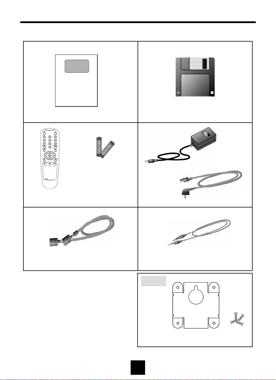
Make sure the following accessories are provided with the product.
TM18U
HTM19U
HTM20U
Color TFT-LCD Monitor
User’s Manual
Manual (*1)
Remote Control (*1)
PC VGA Cable(*1)
Monitor Driver (*1)
DC Adapter (*1)
Size AAA Battery (*2)
AC Cord (*1)
PC Audio Cable (*1)
6
Option
Wall Mount Bracket (*1) / Screws (*4)
Page 7
PREPARATION - Remote Control
Use the remote control by pointing it towards the remote sensor window.
Objects between the remote control and sensor window may prevent proper operation.
!
Cautions regarding use of remote control
Do not expose the remote control to shock. In addition, do not expose the remote control
to liquids, and do not place in an area with high humidity.
Do not install or place the remote control under direct sunlight. The heat may cause
deformation of the unit.
The remote control may not work properly if the remote sensor window of the main unit is
under direct sunlight or strong lighting. In such case, change the angle of the lighting or
LCD TV monitor set, or operate the remote control closer to the remote sensor window.
Batteries for Remote Control
If the remote control fails to operate LCD TV monitor functions, replace the batteries in the
remote control.
1 Open the battery cover.
2 Insert batteries (two Size-AAA batteries, Supplied with product).
Place batteries with their terminals corresponding to the (+) and (-) indications in the
battery compartment.
3 Close the battery cover
!
Cautions regarding batteries
Improper use of batteries can result in a leakage of chemicals and/or explosion. Be sure to
follow the instructions below.
• Place batteries with their terminals corresponding to the (+) and (-) indications.
• Different types of batteries have different characteristics. Do not mix batteries of different
types.
• Do not mix old and new batteries. Mixing old and new batteries can shorten the life of
new batteries and/or cause old batteries to leak chemicals.
• Remove batteries as soon as they are non-operable. Chemicals that leak from batteries
can cause a rash. If chemical leakage is found, wipe with a cloth.
• The batteries supplied with the product may have a shorter life expectancy due to storage
conditions.
• If the remote control is not used for an extended period of time remove batteries from the
remote control
7
Page 8
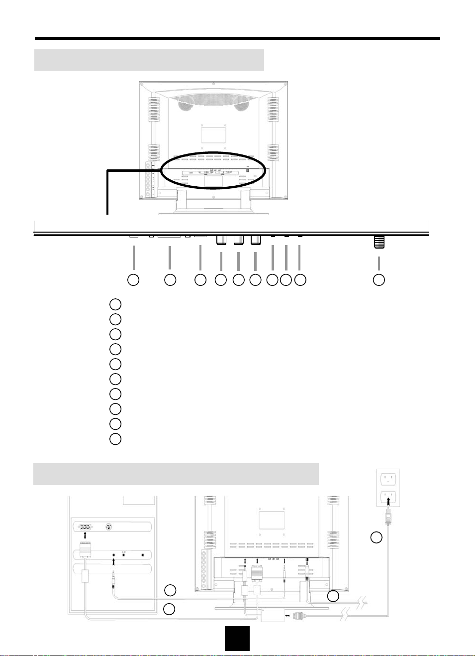
PREPARATION – Cable Connection
Cable Connector Description
1 2 3 4 5 6 7 8 9 10
1
Power Input : DC 12V
2
Analog RGB : PC VGA Cable
3
S-Video
4
Composite Video : Yellow
5
Video Sound (L) : White
6
Video Sound (R) : Red
7
PC Audio Input
8
Headphone Output
9
Line Out : Connect to another speaker set
10
Antenna
VGA, Power, Audio & Antenna Cable Connection
7
2
8
1
10
Page 9
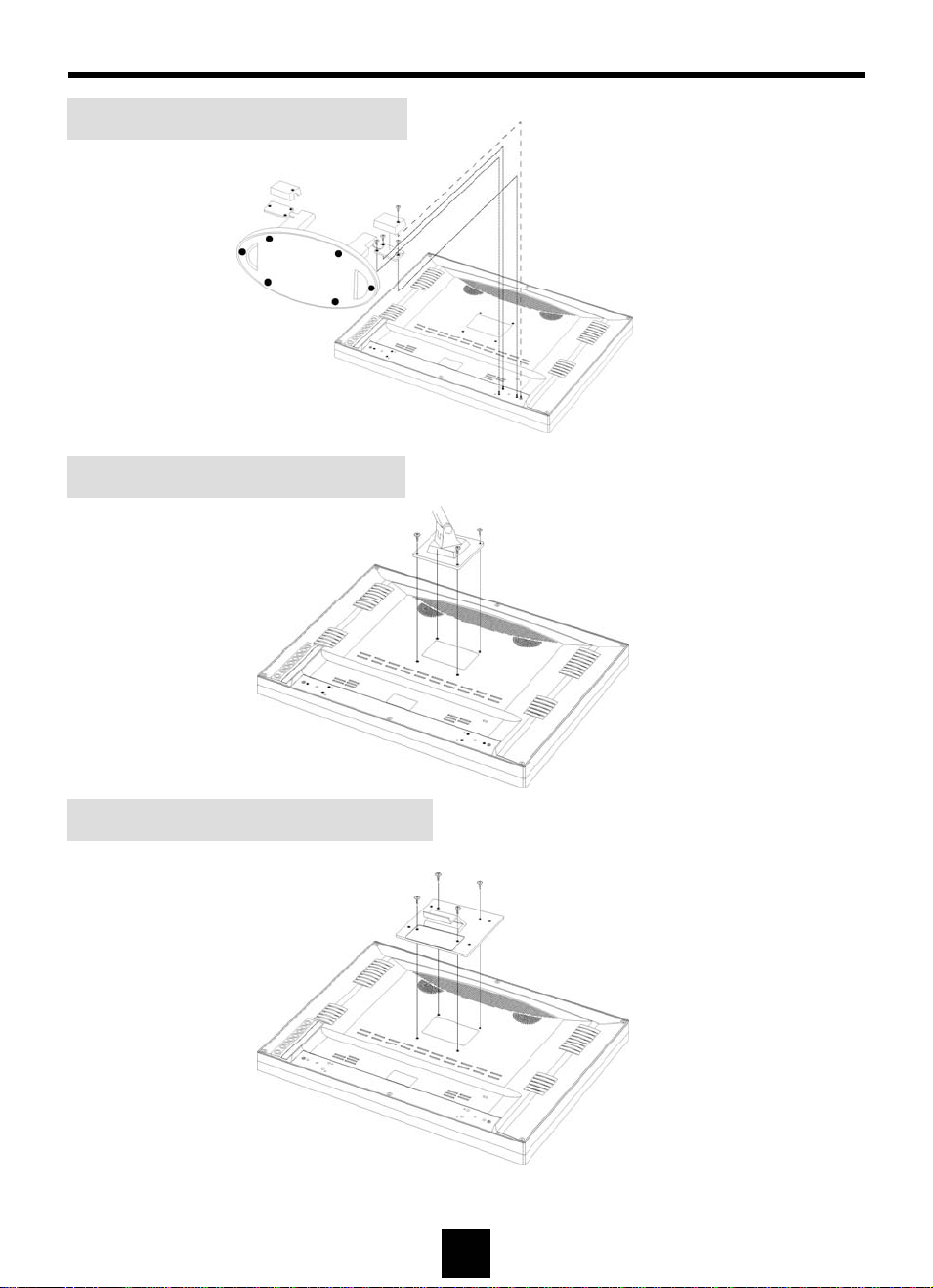
PREPARATION- Stand, Arm, Wall Mount
Stand Installation (Standard)
Arm Installation
Wall Mount Bracket Installation
Note : Arm and wall mount are sold separately
9
Page 10
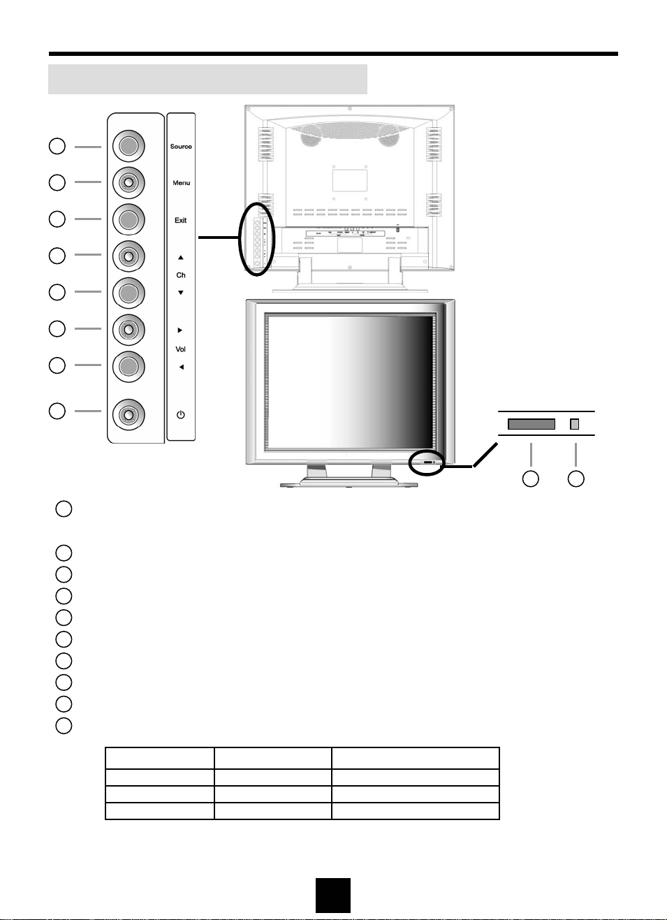
LOCATION OF CONTROL PANEL
Control Panel on the front of main unit
1
2
3
4
5
6
7
8
Back
Front
9 10
1
Signal Source Select : Signal source will be selected in sequence as
the button is pressed.
2
Menu : Display the menu window and used as Sel e ct button.
3
Exit : Return to previous OSD menu or exit from O S D menu window.
4
Channel up / Move up : Channel up or move upward in OSD menu.
5
Channel down / Move down : Channel down or move downward in OSD menu.
6
Increase volume / Move right : Volume up or move rightward in OSD menu.
7
Decrease volume / Move left : Volume down or move left ward in OSD menu.
8
Power On/ Off
9
Remote Control Sensor
10
Power Indicator
Mode LED Display Remark
Power on Green LED
Power off
Orange LED
Dark LED
No Signal (PC mode)
-
-Switch Off
10
Page 11
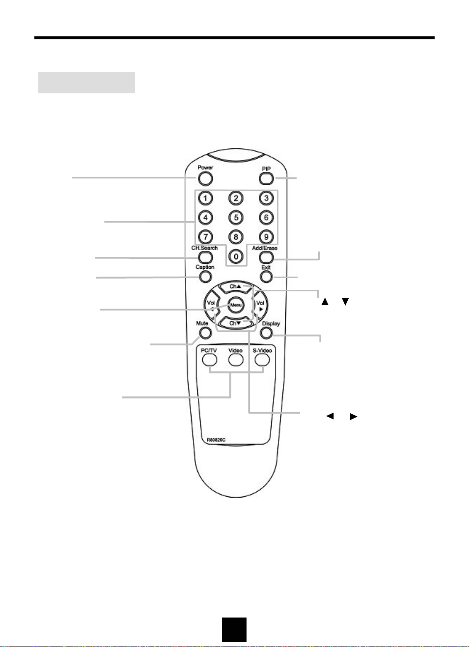
REMOTE CONTROL
Remote Control
Power
Channel Select
Auto Program
Caption
Menu/Selection
Sound Mute
- Press –Sound off
- Press again –Resume Sound
Signal Source Select
PIP
Press – PIP ON
Press again – PIP OFF
Channel Add / Erase
Press – Display Channel Add Menu
Press again - Display Channel Erase Menu
Exit - Exit the OSD menu or move
to previous menu.
Ch ( )/( )
Selects next higher channel.
Selects next lower channel.
Display
Press - Display signal source name.
Vol ( )/ ( )
Increase volume (up)
Decrease volume (down)
11
Page 12
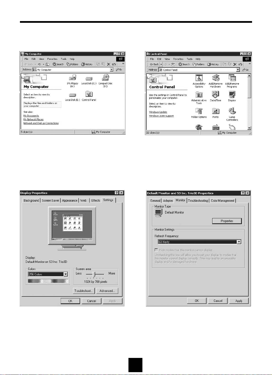
MONITOR INSTALLATION
The instruction below is for Windows 2000.
1 Double click [Control Panel ] icon
from [My Computer] folder
.
2 Double click [Display] icon from
[Control Panel] folder.
3 Select [Settings] in [Display Properties]
window.
4 Click [Advanced...].
5 Select [Monitor] in the window shown
above.
6 Click [Properties].
12
Page 13

MONITOR INSTALLATION(Continued)
8 [Upgrade Device Driver Wizard] will be
appeared. Select the
then click [Next>].
7 Select [Driver] and then click [Update
Driver...]
.
second list and
9 Click [Have Disk...].
10 When drive [A:] appears in default,
click [Browse…] to select CD-ROM drive.
13
Page 14
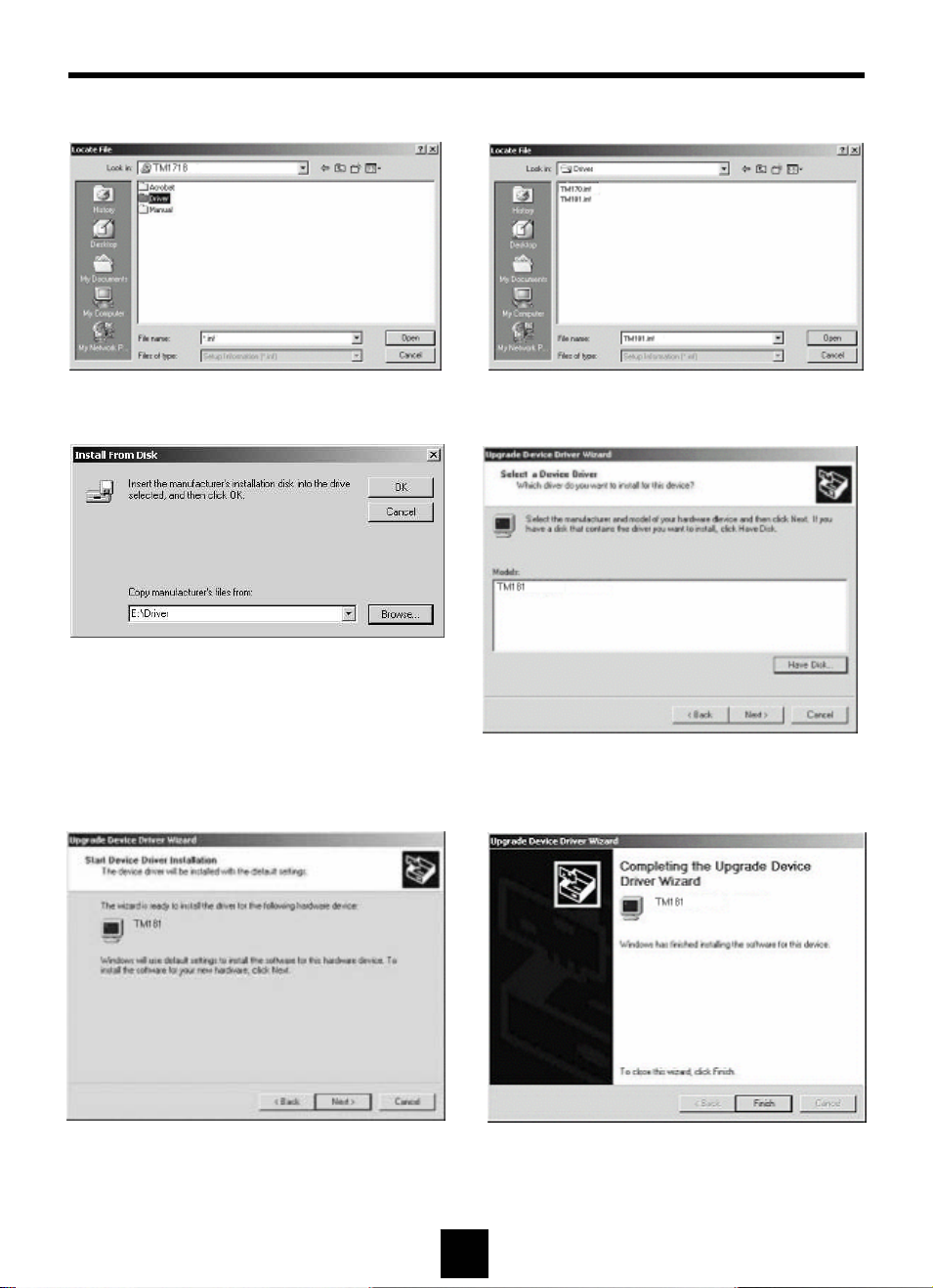
MONITOR INSTALLATION(Continued)
11 Double click the [Driver] folder. 12 Choose the product Inf. file then click [Open].
13 Click [OK] to proceed to the next step.
14 Choose the product Inf. file ,
then click [Next>] to proceed to the next step.
15 Click [Next>] to start installation. 16 Click [Finish].
(Be sure the screen shows correct model name.)
14
Page 15
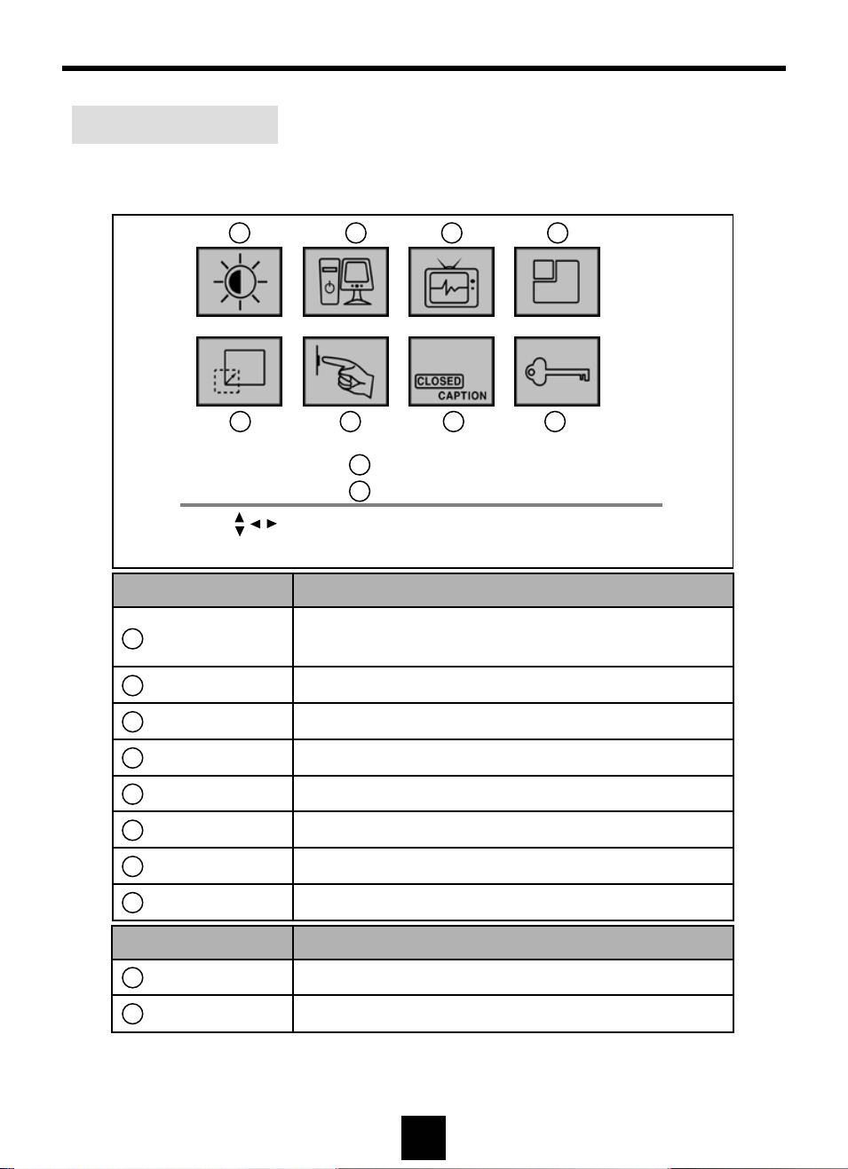
STATUS INFORMATION
Status Infomation
Press “Menu” button on control panel or remote control to activate the OSD menu
window.
1 2 3 4
5 6 7 8
9
Resolution : 1280 x 1024
Frequency : 63.9 KHz 60Hz
10
Move Menu : Select Exit
Menu Icon Menu Items
1
Video
2
PC Auto Adjustment, Frequency, Phase, Position
3
PIP PIP On/Off, Source, Position, Sound
4
TV Manual Store, Auto Store, Fine Tune, Erase, Sort
5
Scaling Normal/Aspect Ratio, Zoom, Pan
6
Setup OSD Languages, OSD Position, OSD Timer, Mute
7
Closed Caption Caption On/Off, Mode, Channel, Field
8
V-chip TV Guidelines, MPAA rating
Brightness, Contrast, Sharpness, Color Control
(Color, Tint, Color System – Video / TV mode only)
Information Description
9
Resolution Number of horizontal & vertical pixels.
10
Frequency Horizontal & vertical frequency.
15
Page 16
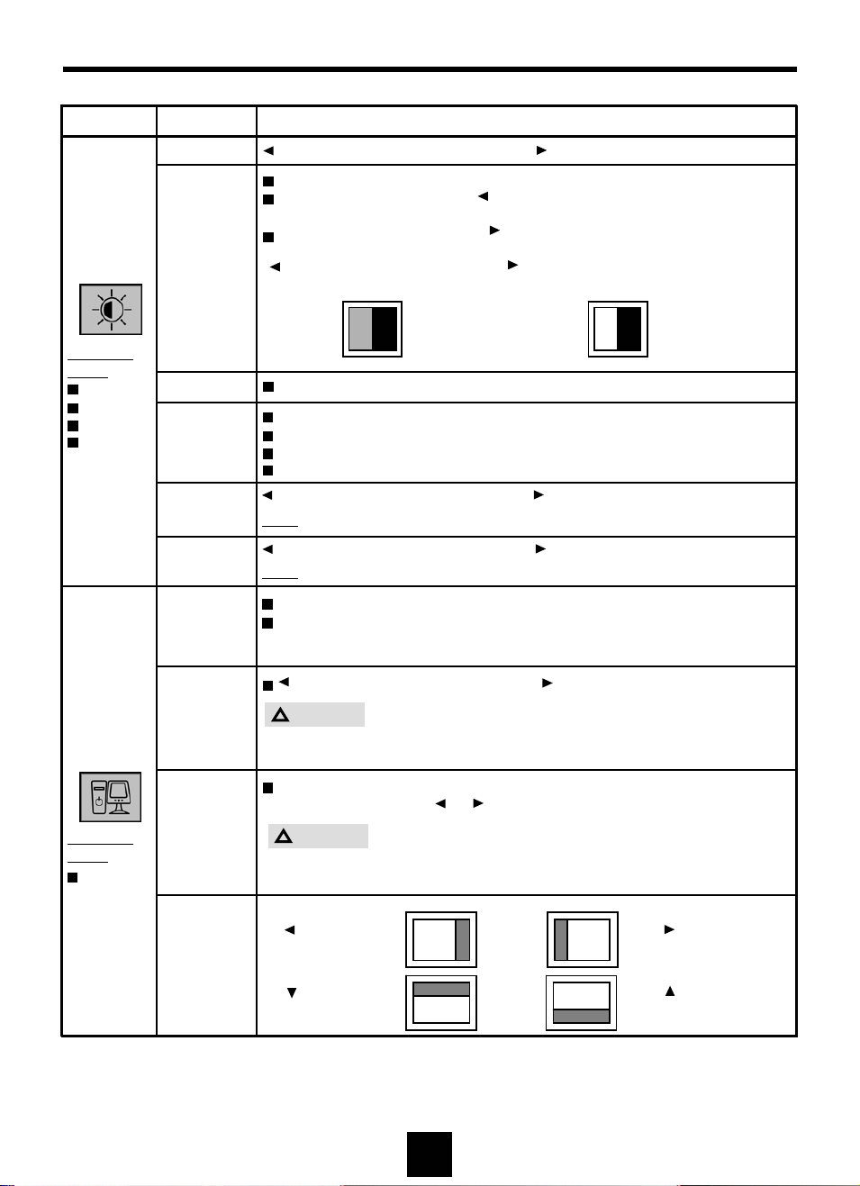
OSD USAGE
Main Menu Sub Menu Operation
Brightness Button : Decrease Brightness Button : Increase Brightness
Contrast is ratio of luminance between black and white.
When contrast is reduced ( button), the luminance of white is
reduced and the display becomes darker.
When contrast is increased ( button), the luminance of white is
increased and the display becomes more clear.
Video
Available
Mode
PC
TV
Video
S-Video
Contrast
Sharpness
Color
Control
Color
Button : Decrease Button : Increase
Contrast Contrast
W BWB
Adjust the clearness of image by controlling its sharpness.
Cold : Greenish white. Felt cold.
Normal : Normal white
Warm : Reddish white. Felt warm.
Custom : Able to adjust the color by controlling Red, Green, and Blue
Button : Lower color intensity Button : Higher color intensity
Note
: Available in Video/TV mode only
PC
Available
Mode
PC
Tint
Auto
Adjustment
Frequency
Phase
Position
Button : Toward green Button : Toward purple
: Available in Video/TV mode only
Note
“Auto Adjustment” performs adjustment of image quality automatically.
Automatically adjusted items are :
1) Clock 2) Phase 3) Position is centered
4) Turning a zoomed picture into its normal shape (100%)
Button:Decrease horizontal size Button:Increase horizontal size.
!
Caution
Perform this adjustment just in the case of having horizontally
unmatched picture after operating the "Auto".
When noise remains on the screen after operating the "Auto Adjust",
adjust it by selecting or button.
!
Caution
Do not make manual adjustment when the picture is in its normal
shape or you will create problem on it..
Button :
Move left
Button :
Move down
deo
Video
Vid
Video
Button :
Move right
Button :
Move up
16
Page 17
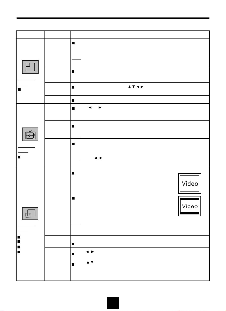
OSD USAGE(Continued)
Main Menu Sub Menu Operation
Select On to activate and Off to deactivate the PIP window.
PIP
Available
Mode
PC
TV
Available
Mode
TV
PIP
Source
Position
Sound Swap the sound source between PIP and PC.
Channel
System
Auto
Prog.
Add/Erase
Note
: The channel(TV mode) and volume of PIP signal source can
be controlled without OSD menu on.
Select a source for PIP display
- Video / S-Video / TV
Move the PIP window with buttons.
Keep pressing the button enable the PIP window move continuously.
Press or button to select a channel system.
Select OK to start auto program.
Note
: To stop auto program, press Exit key.
Select “Add” to add current channel to channel table, and select
“Erase” to delete current channel from channel table.
Note
: Use buttons to select Add or Erase.
Add/Erase button of remote control does the same function.
Normal
Display in full screen.
For example, XGA(1024x768 pixels) will be
displayed like the figure.
Off / On
ANT / CATV
Scaling
Available
Mode
PC
TV
Video
S-Video
Aspect Ra tio
Scaling
Zoom Able to zoom the screen by up to 64 times.
Pan
Display in original aspect ratio of resolution.
For example, XGA(4:3) will be displayed like
the figure in TM18U/HTM19U.
Note
: The resolution of TM18U/HTM19U is 1280x1024(SXGA) which
is 5:4 aspect ratio and HTM20U is 1600x1200(UXGA) which is
4:3 aspect ratio.
Use button to adjust the horizontal position of Zoomed
window.
Use button to adjust the vertical position of Zoomed window
Note: Not possible to move normal screen.Just works in Zoomed
window.
17
Page 18
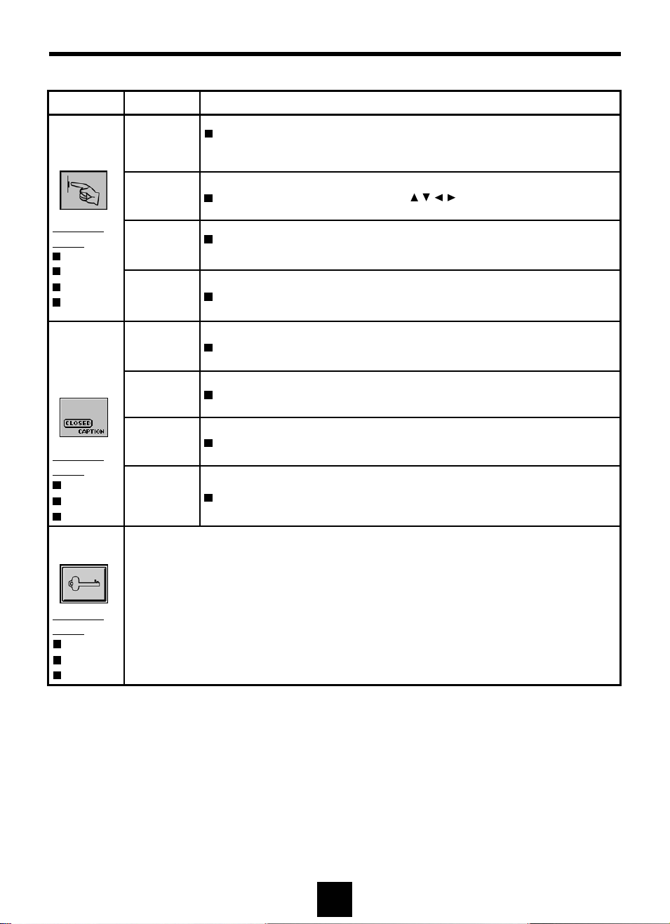
OSD USAGE(Continued)
Main Menu Sub Menu Operation
Setup
Available
Mode
PC
TV
Video
S-Video
Closed
Caption
(US Only)
Available
Mode
TV
Video
S-Video
V-Chip
(US Only)
Language
Position Adjust the OSD position by using buttons.
Timer
Mute Select On to off the sound and Off to resume the sound
Caption Select On to enable caption, and Off to disable caption.
Mode Select Caption or Text mode.
Channel Select “1”or “2”.
Field Select “1”or “2”.
Refer to the Appendix
Select the language of OSD menu
- English / Français / Español / Deutsch
The range of controlling the duration time of the OSD menu is
from 5 sec. up to 50 sec.
Available
Mode
TV
Video
S-Video
18
Page 19
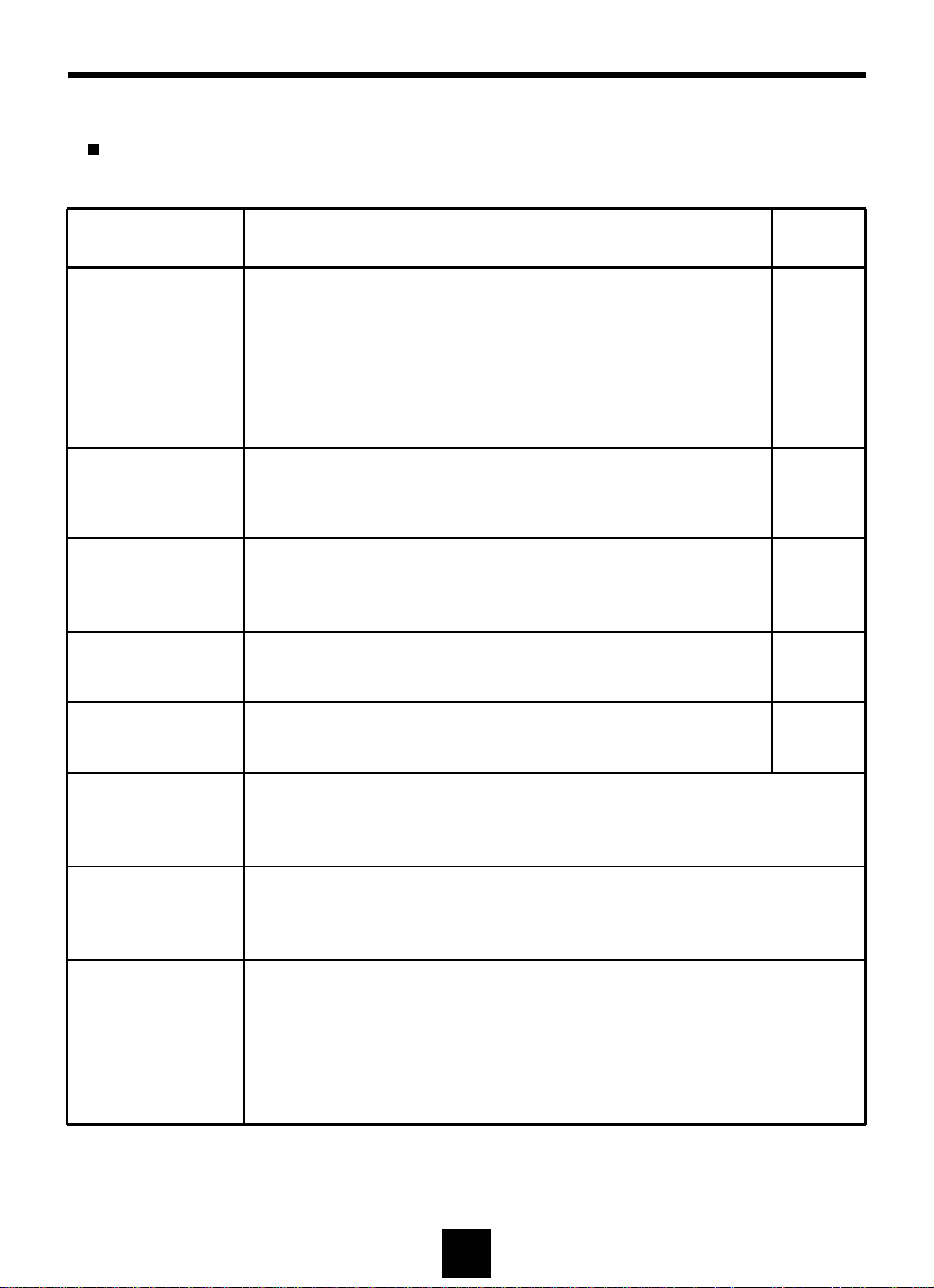
BEFORE CALLING FOR REPAIR SERVICE…
Before calling for repair service, check the following items for possible remedies to the
encountered symptoms.
Problem Check below
There is no
picture or sound
(TV,Video,PC).
There is no
sound (TV,Video
PC).
There is no
picture or sound,
just noise(TV).
Picture is not
clear (TV).
Picture is not
clear (PC).
• Make sure the AC adapter is properly inserted in the
power outlet.
• Make sure the main power button of the main unit is on.
• Make sure the signal cable is free of connections.
• Make sure whether the power of an external input device
is on.
• Make sure the input mode is set to proper mode.
• Make sure the volume is not set to minimum.
• Make sure the sound is not set to mute.
• Make sure the sound cable is free of connections.
• Make sure the antenna cable is properly connected.
• Bad reception can be considered.
• Make sure the antenna cable is properly connected.
• Bad reception can be considered.
• Operate the "Auto Adjustment".
• Adjust the Frequency and the Phase.
Reference
Pages
8
10,11
8
-
10,11
10,11
11
8
8
-
8
-
16
16
The picture is not
sharp (TV).
The picture is
doubled or tripled
(TV).
There are stripes
on the screen or
color fade.
• The reception may be weak.
• The state of broadcast may also be bad.
• Make sure the outside antenna is not connected.
• Make sure the antenna is facing the right direction.
• There may be reflected electric waves from mountains
or buildings.
• Check this unit receiving interference from other devices.
Transmission antennas of radio broadcasting stations and
transmission antennas of amateur radios and cellular
phones may also cause interference.
• Use the unit as far apart as possible from devices that may
cause possible interference.
19
Page 20
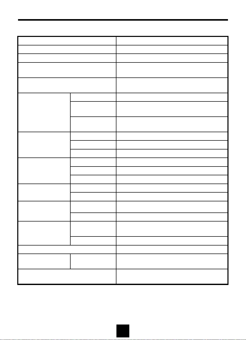
SPECIFICATIONS
TM18U/HTM19U
Resolution 1280 * 1024, SXGA
Color 16,777,216 Colors (Full Color)
Brightness 250 cd/m
Contrast Ratio
Viewing Angle
Panel
PC Signal
(Analog RGB)
Video
TV
Type Amorphous Si TFT-LCD
Actual Display Size
Diagonal Length
H- Frequency 30~80 KHz
V- Frequency 56~75 Hz
Signal Level 0.7Vp-p
Input Signal CVBS / S-VIDEO
Color Signal Type PAL / NTSC /SECAM
Sound Signal Type Stereo
Channel System NTSC M
Sound Signal Type Mono
TM18U : 400 : 1
HTM19U : 500 : 1
TM18U : 160 ° (H) / 160 ° (V)
HTM19U : 170 ° (H) / 170 ° (V)
TM18U : 357.12(H) x 285.696(V) mm
HTM19U : 376.32(H) x 301.056(V) mm
TM18U : 18.0", 457.34 mm
HTM19U : 19.0”, 481.92 mm
2
(nit)
Power Voltage
Input
Output DC 12V
On
Power Consumption
Off-Mode Max. 3 Watt
Speaker 1 Watt x 2
Size W*H*D
Weight (w/o accessories)
AC100~240V, 50/60Hz
TM18U : Max. 45 Watt
HTM19U : Max. 45 Watt
485 x 383 x 57 mm ,
174 mm (Stand Depth)
TM18U : 7.0 Kg
HTM19U : 7.2 Kg
20
Page 21
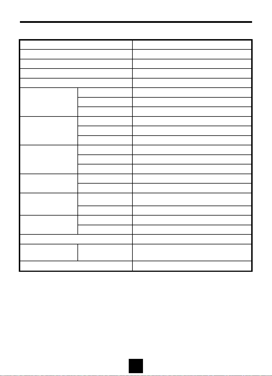
SPECIFICATIONS
HTM20U
Resolution 1600 * 1200, UXGA
Color 16,777,216 Colors (Full Color)
2
Brightness 250 cd/m
Contrast Ratio 350 : 1
Viewing Angle 160 ° (H) / 160 ° (V)
Type Amorphous Si TFT-LCD
Panel
PC Signal
(Analog RGB)
Video
TV
Actual Display Size 408.0(H) x 306.0(V) mm
Diagonal Length 20.1", 510.54 mm
H- Frequency 30~80 KHz
V- Frequency 56~75 Hz (UXGA is for only 60Hz )
Signal Level 0.7Vp-p
Input Signal CVBS / S-VIDEO
Color Signal Type PAL / NTSC /SECAM
Sound Signal Type Stereo
Channel System NTSC M
Sound Signal Type Mono
(nit)
Power Voltage
Input
Output DC 18V
On Max. 65 Watt
Power Consumption
Off-Mode Max. 3 Watt
Speaker 1 Watt x 2
Size W*H*D
Weight (w/o accessories) 8.2 Kg
AC100~240V, 50/60Hz
485 x 383 x 57 mm ,
174 mm (Stand Depth)
21
Page 22
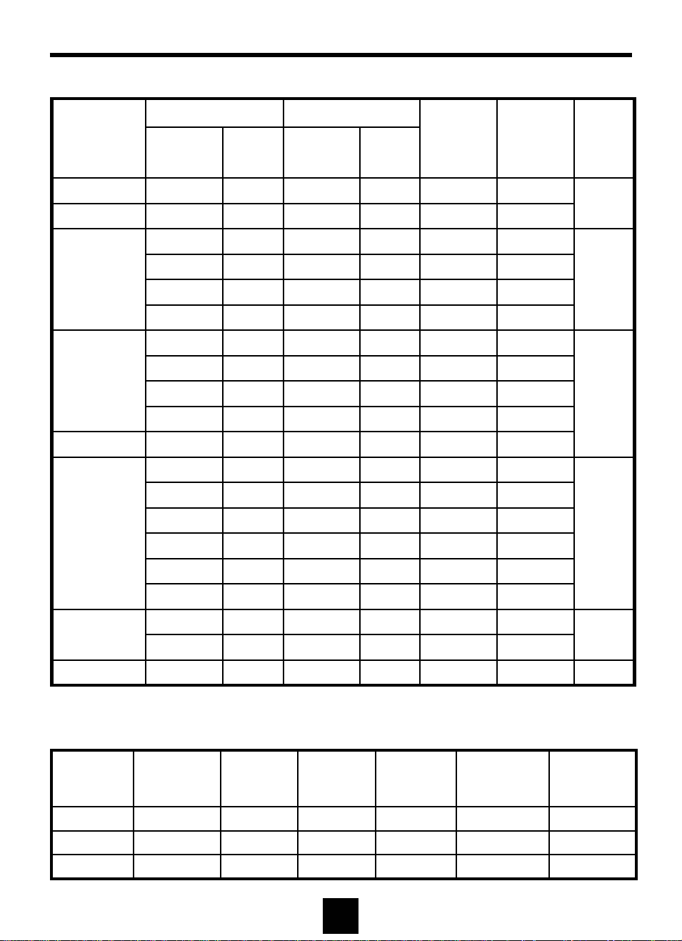
SPECIFICATIONS
Available PC VGA Mode
Vertical Horizontal
Resolution
Frequency
(Hz)
Polarity
Frequency
(KHz)
Polarity
Pixel Rate
(MHz)
Standard
Type
Remark
640 x 350 70.09 N 31.47 N 25.175
720 x 400 70.09 P 31.47 N 28.322
59.94 N 31.47 N 25.175
66.67 N 35.00 N 30.240
640 x 480
72.81 N 37.86 N 31.500
75.00 N 37.50 N 31.500
56.25 N/P 35.16 N/P 36.000
60.32 P 37.88 P 40.000
800 x 600
72.19 P 48.08 P 50.000
75.00 P 46.88 P 49.500
832 x 624 74.55 N 49.73 N 57.283
60.00 N 48.36 N 65.000
60.00 N 48.78 N 64.000 MAC
70.07 N 56.48 N 75.000
1024 x 768
72.10 P 57.52 P 75.000 IBM
74.93 N 60.24 N 80.000
75.03 P 60.02 P 78.750 VESA
IBM
IBM
VESA
MAC
VESA
VESA
VESA
VESA
VESA
VESA
MAC
VESA
VESA
MAC
DOS
VGA
SVGA
XGA
60.02 P 63.98 P 108.000 VESA
75.03 P 79.98 P 135.000 VESA
1600 x 1200 UXGA*
* UXGA (1600 x 1200) mode is possible for HTM20D (20.1”).
60.00 P 75.00 P 162.000
VESA
SXGA1280 x 1024
HDTV Input (From Set Top Box)
Vertical
Mode Resolution
480p 720 x 480
720p 59.94 44.96 74.176
1080i 29.97 33.72 74.176
1280 x 720
1920 x 1080
Frequency
(Hz)
59.94 31.47 27.000 SMPTE 293M
Horizontal
Frequency
(KHz)
Pixel Rate
(MHz)
Standard
Type
SMPTE 296M
SMPTE 274M
Remark
Progressive
Progressive
Interlace
22
Page 23

FCC STATEMENTS
This device complies with Part 15 of the FCC Rules. Operation is subject to the following two
conditions: (1)This Device may not cause harmful interference, and (2) This device must accept
any interference received, including interference that may cause undesired operation.
FCC Class B Radio Frequency Interference Statement
WARNING: (FOR FCC CERTIFIED MODELS)
This equipment has been tested and found to comply with the limits for a Class B digital device,
pursuant to Part 15 of the FCC Rules. These limits are designed to provide reasonable protection
against harmful interference in a residential installation. This equipment generates, uses and can
radiate radio frequency energy, and if not installed and used in accordance with the instructions, may
cause harmful interference to radio communications. However, there is no guarantee that interference
will not occur in a particular installation. If this equipment does cause harmful interference to radio or
television reception, which can be determined by turning the equipment off and on, the user is
encouraged to try to correct the interference by one or more of the following measures:
1. Reorient or relocate the receiving antenna.
2. Increase the separation between the equipment and receiver.
3.Connect the equipment into an outlet on a circuit different from that to which the receiver is
connected.
4. Consult the dealer or an experienced radio/TV technician for help.
NOTICE
1. The changes or modifications not expressly approved by the party responsible for compliance could
void the user's authority to operate the equipment.
2. Shielded interface cables and AC power cord, if any, must be used in order to comply with the
emission limits.
3. The manuf
modification to this equipment. It is the responsibilities of the user to correct such interference.
acturer is not responsible for any radio or TV interference caused by unauthorized
23
Page 24
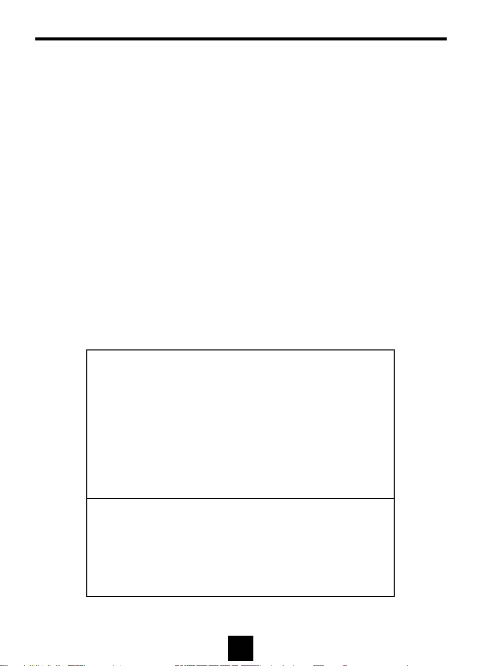
Appendix
V - Chip (US only)
1. Function of V-Chip
The V - Chip can block certain rated television shows off television (if chosen) so children cannot
watch programs that their parents do not approve. The chip in each television will decode
program-rating information which is transmitted along with the television signal. It will then
compare the rating codes with values preset by the viewer, which is meant to be the parents. If
the rating codes are higher than the preset values, the television signal will be blocked, and a
blank screen will be displayed.
2. Setting V-Chip
This product has V-Chip feature and you can set it up via OSD.
1. Select V -Chip on OSD, then enter 4 digits of pin number(Initial pin number is “0000”).
If you enter an incorrect pin number “Incorrect” message will be displayed for 3 seconds.
2. Use arrow keys to change or to activate the highlighted function.
3. Setting up TV Guidelines
Use arrow buttons to move around the matrix and press Menu button to change the
value from "U" to "B" or "B" to "U“.
All FV V S L D
BTV-Y
TV-Y7 B B
TV-G U
TV-PGU UUUU
TV-14 U U U U
TV-MA U U U U
TP-Y : Young Children
TV-Y7: Children 7 and over
TV-G: General Audience
TV-PG: Parent Guidance
TV-14: Viewers 14 and over
TV-MA: Mature Audience
FV : Fantasy Violence
V : Violence
S : Sexual Situation
L : Coarse Language
D : Suggestive Dialog
U : Unblock
B : Block
24
Page 25
Appendix
4. Setting up MPAA rating
Use arrow buttons to move around the matrix and press Menu button to change the value
from "U" to "B" or "B" to "U".
(MPAA : Motion Picture Association of America (movie rating organization))
G U General Audience
PG U Parental Guidance Suggested
PG-13 U Parents Strongly Cautioned
R U Restricted Under 17 Requires
NC-17 U No Children Under 17 Admitted
X U Adult Only
MR U Not Rated
5. Entering a new pin number
- Use numeric keys to enter a new pin number. Pin number confirm menu appears.
- Again, use numeric keys to enter the pin number you entered at the previous step. If the
two pin numbers do not match, "Incorrect" message will be displayed for 3 seconds.
6. Blocking Screen
- If the incoming signal’s rating is higher than the one specified, the screen will be
blanked and "Excessive rating" message will be appeared.
25
 Loading...