

Page 1

®
NCT
100T
®
NCT
990T
®
NCT
Controls for Lathes
Operator`s Manual
Valid from software version x.057
2000T
Page 2

Produced and developed by NCT Automation kft.
H1148 Budapest Fogarasi út 7
: Letters: H1631 Bp. pf.: 26
F Phone: (+36 1) 467 63 00
F Fax:(+36 1) 363 6605
E-mail: [email protected]
Home Page: www.nct.hu
Page 3

Contents
Introduction ............................................................ 7
1 Operator’s Panel ....................................................... 8
1.1 The NC Control Panel: Display Unit and Data Input Keyboard ................. 8
1.1.1 Data Input Keyboard ............................................. 10
1.1.2 Information Displayed in General Displaying Area and the Status Bar ........ 11
1.1.3 Indication of Ready Status of Control ................................ 13
1.2 Machine Control Board .............................................. 13
2 General Operating Knowledge ........................................... 17
2.1 Screen Menu ...................................................... 17
2.2 Action Menu ...................................................... 19
2.3 Data Input ........................................................ 19
3 General Displaying Areas and Actions Executed on Them ..................... 21
3.1 POSITION Screens ................................................. 22
3.2 CHECK Screens.................................................... 24
3.2.1 PROGRAM TEXT Screen, Listing of Running Program .................. 24
3.2.2 FUNCTION Screen, Subprogram and Macro Levels ..................... 24
3.2.3 LAST and ACTIVE screens. G Codes and Compensations................. 25
3.2.4 OPERATOR’S PANEL Screen ..................................... 26
3.2.5 MESSAGES Screen ............................................. 29
3.3 PROGRAM Screens ................................................. 30
3.3.1 DIRECTORY Screen ............................................ 30
3.3.2 VIEW Screen .................................................. 32
3.3.3 EDIT Screen ................................................... 33
3.3.4 BLOCK INPUT ................................................ 34
3.4 OFFSETS Screens .................................................. 35
3.4.1 WORK OFFSETS Screen ......................................... 35
3.4.2 TOOL OFFSETS Screen.......................................... 36
3.4.3 WORK OFFSET MEASURE Screen ................................ 39
3.4.4 TOOL LENGTH OFFSET MEASURE Screen ......................... 40
3.4.5 RELATIVE POSITION OFFSETS Screen ............................ 41
3.5 GRAPHIC POSITION Screens ........................................ 42
3.5.1 GRAPHIC PARAMETERS Screen .................................. 42
3.5.2 DRAW Screen.................................................. 44
3.6 SETTING Screens .................................................. 46
3.6.1 Screen of LOCAL MACRO VARIABLES ............................ 46
3.6.2 Screen of COMMON MACRO VARIABLES #100–#199 ................. 47
3.6.3 Screen of COMMON MACRO VARIABLES #500–#599 ................. 48
3.6.4 TIMER AND COUNTER Screen ................................... 49
3.6.5 TOOL POT TABLE Screen ....................................... 49
3.6.6 PLC TABLE Screen ............................................. 51
3.6.7 USER’S PARAMETERS Screen (User’s Params) ....................... 52
3.6.8 SECURITY PANEL Screen ....................................... 53
4 Editing Part Programs ................................................. 56
Page 4

4.1 Structure of Part Program ............................................ 56
4.2 Division of EDIT Screen during Editing.................................. 57
4.3 Basic Editing Functions: Typing, Cursor Moving, Delete, Insert, Select .......... 59
4.4 Editor Action Menu................................................. 62
4.5 File Actions: Save, Save as ........................................... 62
4.6 Edit Actions: Undo, Cut, Copy, Paste, Find and Replace ..................... 62
4.7 Insert Actions ..................................................... 64
4.8 Actions of Window ................................................ 64
4.9 Help ............................................................ 65
5 Switching Over Operation Modes ........................................ 66
6 Manual Operation Modes .............................................. 67
6.1 Manual Reference Point Return Mode ................................... 67
6.2 Jog Mode ........................................................ 69
6.3 Incremental Jog Mode ............................................... 71
6.4 Manual Handle Mode ............................................... 73
7 Actions Executed in Manual Operation Modes ............................. 75
7.1 Single Block Operation .............................................. 75
7.2 Work Zero Point Offset and Tool Length Offset Measurement . . .............. 75
7.2.1 Work Zero Point Offset Measurement ............................... 76
7.2.2 Tool Length Offset Measurement inside the Machine .................... 79
7.2.3 Automatic Tool Length Offset Measurement .......................... 81
7.2.4 Calibrating Tool Offset Sensor ..................................... 82
8 Modes of Automatic Operation .......................................... 85
8.1 Automatic Mode ................................................... 85
8.1.1 Program Execution in DNC ....................................... 85
8.2 Edit Mode ........................................................ 87
8.3 Manual Data Input Mode............................................. 88
9 Override Switches ..................................................... 90
9.1 Feedrate Override Switch ............................................ 90
9.2 Rapid Traverse Override Switch ....................................... 91
9.3 Spindle Speed Override Switch ........................................ 91
10 Program Execution Start and Stop ...................................... 93
10.1 Starting Program Execution.......................................... 93
10.2 Feed Stop ....................................................... 93
10.3 RESET ......................................................... 93
10.4 Programmed Stop: M00 ............................................ 94
10.5 Conditional Stop: M01 ............................................. 94
10.6 End of Program: M02, M30.......................................... 95
11 Intervention in the Course of Program Execution .......................... 96
11.1 Conditional Block Skip ............................................. 96
11.2 Increasing Feedrate by Means of Rapid Traverse Jog Button . ................ 96
11.3 Intervention by Means of Manual Handle in Automatic Operation ............. 97
12 Debugging the Part Program ........................................... 99
Page 5

12.1 Single Block Execution.............................................. 99
12.2 Dry Run (All Feedrates at High Speed).................................. 99
12.3 Machine Lock Function ............................................ 100
12.4 Other Locking Possibilities .......................................... 100
12.5 Test Run........................................................ 101
13 Interruption and Restart of Automatic Operation ......................... 102
13.1 Interruption of Automatic Operation................................... 102
13.2 Restart of the Automatic Operation. Modal Information. ................... 102
13.3 Unconditional Restart of Automatic Operation ........................... 104
13.4 Automatic Operation Restart with BLOCK RESTART Condition . . .......... 109
13.4.1 Return to the Block Start Position by Means of Manual Operation......... 109
13.4.2 Return to Block Start Position in Automatic Mode .................... 109
13.4.3 Cases of Return by Means of BLOCK RESTART Condition ............. 110
13.5 Automatic Mode Restart with BLOCK RETURN Condition ................ 113
13.5.1 Return to the Interruption Point by Means of Manual Operation .......... 113
13.5.2 Return to the Interruption Point in Automatic Operation . ............... 113
13.5.3 Cases of Return by Means of Condition BLOCK RETURN.............. 114
13.6 Automatic Operation Start after Block Search ........................... 117
13.6.1 Pointing at the Desired Block. Entering the Repetition Count. ............ 117
13.6.2 Command SEARCH ........................................... 118
13.6.3 Command GOTO ............................................. 120
13.6.4 Search for INTERRUPTED Block ................................ 120
14 Listing of Messages and their Codes ..................................... 122
14.1 Local Message ................................................... 122
14.2 Global Messages.................................................. 122
14.3 Listing of Global Messages.......................................... 124
Notes ................................................................ 143
Alphabetical index ..................................................... 144
March 18, 2003
Page 6

© Copyright NCT March 18, 2003
The Publisher reserves all rights for the contents of this Manual. No reprinting, even in
extracts, is permissible unless our written
consent is obtained. The text of this Manual
has been compiled and checked with utmost
care, yet we assume no liability for possible
errors or spurious data and for consequential losses or damages.
Page 7

Introduction
Introduction
Dear User,
Thank you for having opted for one of our NCT100T, NCT990T, or NCT2000T control
systems. It is hoped sincerely that you will be always satisfied in your work with its facilities.
It should be remembered that the skill of operating the machine can only be learnt in the
possession of the part programming fundamentals. Similarly, no programming is feasible unless
the skills of machine operation are acquired.
THE MACHINE CANNOT BE MANIPULATED OR OPERATED IN SAFETY UNLESS
YOU CAN INTERPRET THE PART PROGRAM AND CHECK IT FOR CORRECT-
NESS!
THE OPERATOR OF THE MACHINE MUST ALWAYS FORESEE ALL CONSE-
QUENCES OF HIS/HER INTERVENTIONS!
Conditions of Operation and Storage
The control system may be operated at an ambient temperature between +10 and +50/C; It
must not be turned on at any other temperature. The programs in the memory cannot be
warranted for preservation if the control is stored at a temperature below +10/C. The storage
temperature range is -10 to +50/C.
The control unit is cooled by one or two built-in fans. The fan with a filter, mounted on top of
the electronic section, should produce a slight over-pressure inside the cabinet. It should be
made sure that the external and the built-in fans are not working against each other. The
cleanliness of the filter of the external fan, or if necessary, a replacement thereof is a basic
condition for the faultless operation of the control system. It is forbidden to open the door of
the cabinet of electronic section (or to disassemble the unit) for aeration or any other purpose
while the control system is under power. It is also forbidden and involves the loss of the
warranty to remove, repair or subsequently adjust the PC boards of the control system. The
only exceptions are the replacements of the 1.6 and 6.3 fuses on the front panel of the PC
board of the power supply, and setting the brightness control of the screen. Replacement of
fuses can only be done if the tool machine is in power-off status.
7
Page 8
1 Operator’s Panel
1 Operator’s Panel
1.1 The NC Control Panel: Display Unit and Data Input Keyboard
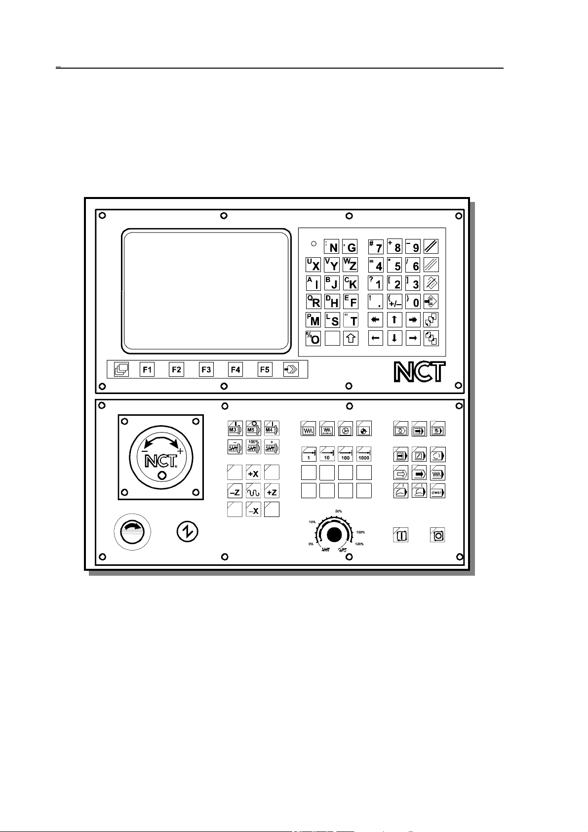
The NC control panel employs the display unit (monitor), the softkeys beneath, and the
data input keyboard.
The NCT100T, NCT990T and the NCT 2000T control panels are available in different
versions. The monitor can be 9" monochrome, or 15" color.
Operator’s panel with 9" monochrome monitor and with optional Machine control
board
8
Page 9
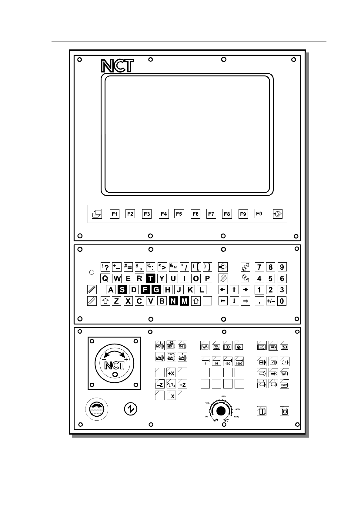
1 Operator’s Panel
Operator’s panel with 15" color monitor and with optional Machine control board
9
Page 10

1 Operator’s Panel
1.1.1 Data Input Keyboard
In case of a 9" monitor directly beneath the screen are five softkeys, in case of a 15" monitor
ten softkeys built together with the screen. In both cases the meaning of these softkeys can be
read in the menu bars found in the bottom line of screen, therefore their meanings may alter.
However it is likely, that in some right-side menu bar there are no captions. This can only
mean, that in that situation the softkeys have no function at all.
To the left of the first softkey is the
screen menu key , while to the right of the last softkey is the
action menu key . The meaning of these keys is permanent and serve for changing
the meaning of softkeys.
The data- input keyboard may be found beneath or to the right of the monitor. The LED “NC
ready” is placed on the data- input keyboard.
The main key groups found on data input keyboard are as follows::
Delete keys:
RESET for deleting global and
CANCEL for deleting local messages.
Alphabetical keys:
On the panel the letters of English alphabets, the space key without a caption as well as key
SHIFT can be found. In case key SHIFT is held down, and at the same time a letter key
is pressed, the symbol indicated at the top left corner of the key appears.
Numeric input keys:
The numeric input keys (digits, decimal point, sign reverser) are beside the letters in a
separate block that gathers up 3x4 keys.
Scrolling and editing keys:
Arrow keys and move the cursor on characters within a word.
When editing part programs (using EDIT screen) their meanings are:
: Enter (Line Feed s)
: Backspace
Arrow keys and naturally move the cursor in the indicated direction on the
address chain.
Arrow keys and move the cursor from one block to another in the
indicated direction.
10
Page 11

1 Operator’s Panel
Keys PgUp and
PgDn are used for turning pages within the text.
Keys INS and
DEL serve for inserting and deleting characters.
The above listed units (monitor and keyboard) constitute the permanent part of NC and are
transported together with the control in any case of configuration.
The NC keyboard is fitted with repeater-type keys. This means
) that a depressed key produces an immediate effect,
) that a held-down key produces an effect again after a programmed delay (Typematic Delay),
) that, with the key held down permanently, the appropriate code will be entered into t he
CPU of the system over and over again at a programmed rate (Typematic Rate).
The delay (TD) and the rate (TR) can be set with the help of parameter 1121 TYPEMATIC
(for details see Parameters).
1.1.2 Information Displayed in General Displaying Area and the Status Bar
Information seen in general displaying area can be divided into 3 parts:
– in the bottom line are the fields of current captions of softkeys,
– above - in the middle of screen - is the general displaying area,
– while the top three lines form the status bar.
The Status Bar
The top three lines give a general outlook on the present status of control and machine tool.
The content of this displaying area is permanent, no matter which general screening area is
selected.
In the first line there are eight status fields. Each status field can only display logically
connecting states. In case there are more states to be displayed in one status field (for there are
simultaneously more state conditions), the last one in the list below is shown.
1 State of First Operation Mode Group
– MDI: manual data input mode
– AUTM: automatic mode, program execution from memory
– AUTD: automatic mode, program execution from external device
– EDIT: edit mode
2 State of Second Operation Mode Group
– JOG: jog mode
– INCR: incremental jog mode
– HNDL: manual handle feed mode
– REF: manual reference point return mode
– SBEX: execution of a single block
11
Page 12

1 Operator’s Panel
3 Functional State of Automatic and Manual Data Input
– NSCH: block search
– INTD: automatic execution interrupted
– STRT: start state
– STOP: stop state
4 Program Manipulation State
– LOAD: loading program from external device
– SAVE: saving program to external device
– SORT: sorting programs in directory is in progress
– EDIT: long-lasting edit operation
– WFTG: waiting for trigger
– TRGD: triggered
– Exch: change between general displaying areas is in progress
– BURN: burning into FLASH
5 Interpolator State
– MOV: either axis moves (interpolator started)
– DWL: waiting specified by dwell G4
– POS: waiting for in position signal
– 1: increment size is 1 increment
– 10: increment size is 10 increment
– 100: increment size is 100 increment
– 1000: increment size is 1000 increment
– feedrate: feedrate value from table
– DRUN:dry run
– HOLD: feed hold state
6 PLC State
– FIN: execution of a PLC function is in progress
7 Message Line State
– #*®!: # mirror, * scaling, ® active rotation, and ! the common offset is not zero
– OPRM: operator’s message in message line
– PLC: PLC message in message line
– ALRM: alarm message in message line
– ! !: access forbidden
– º»: conflicting state
8 General NC State
– REF: no reference point on an axis
– TEST:test mode
– LOCK: machine lock state
– EMG: emergency stop state
– KYBD: no connection to keyboard
In the second line is the message field. In this field the global messages, i.e. messages
independent of the general displaying area, alarm messages of NC, PLC and macros as well as
12
Page 13

1 Operator’s Panel
the operator’s messages of PLC are displayed. The date and time display can also be found in
this line.
In the third line the name of the active general displaying area and behind the number of
programs indicated for running can be read. In case of manual data input mode, the number
of programs belonging to the manual data input can be seen here, otherwise the number of
programs indicated for automatic mode is displayed.
1.1.3 Indication of Ready Status of Control
The light of the LED "NC ready" indicates the power-on and functional ready condition of the
control system.
The LED will turn dark
– upon power-off of the control system,
– if the control breaks down,
– if the monitoring program (watchdog) of the control detects a malfunctioning or a fatal
error.
If the LED is dark, the control is out of service!
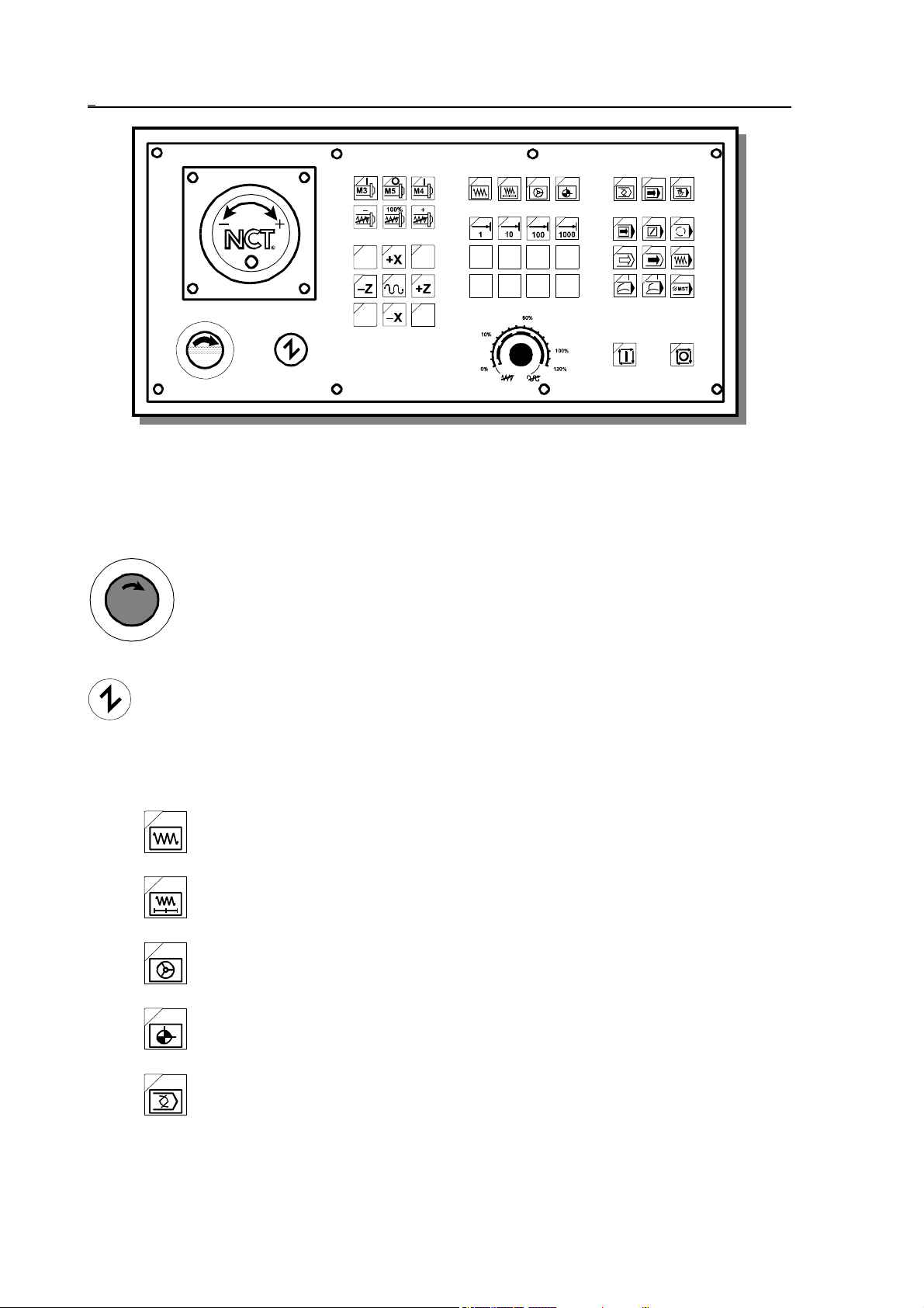
1.2 Machine Control Board
The operation mode and functional state of the machine must be capable of being changed and
the machining must be capable of being started and stopped. The buttons and switches
influencing the function of the machine are called machine control items. The machine control
items can be operated
– partly after selecting the appropriate general displaying area by means of softkeys on NC
keyboard, or
– by means of buttons, switches installed separately.
A summary of the state of control items, the active mode ect. appears if the CONTROL
PANEL screen is selected.
The machine control panel must contain primarily those operating items, that cannot be
accessed from the data input keyboard by means of softkeys (e.g. START, STOP), or their
access is hard. Certain items of the machine keyboard can make the intervention from data
input keyboard through softkeys unnecessary. Of course the developed machine keyboard can
also activate all, from data input keyboard through softkeys attainable machine control items.
The case, whether an operating item is to be accessed from softkeys or only from machine
control panel is determined by the machine tool builder as a function of the developed machine
keyboard, so for details turn to him for an information material.
13
Page 14
1 Operator’s Panel
Optional machine control board
Bel
ow the operating items of machine control board delivered by NCT are described. The lighting
state of LED in the top left corner of buttons shows, that the function indicated by the key is
active.
Emergency stop. By its depressing the NC registers the emergency stop state,
shuts down all movements, and cut s its outputs off the machine. It can be
undone by rotating the head of the button in the direction of the arrow. For
more details of its functioning turn to the machine tool builder for an
information material.
Machine on button. By affecting it, if the machine is not in emergency stop state (e.g.
the emergency stop is not in held down state) the control and the machine link. Other
parts of the machine, e.g., hydraulics, etc. come into effect. For more details about the
power-on process of the machine turn to the machine tool builder.
Operation mode selectors:
Jog
Incremental jog
Manual handle
14
Manual reference point return
Edit
Page 15
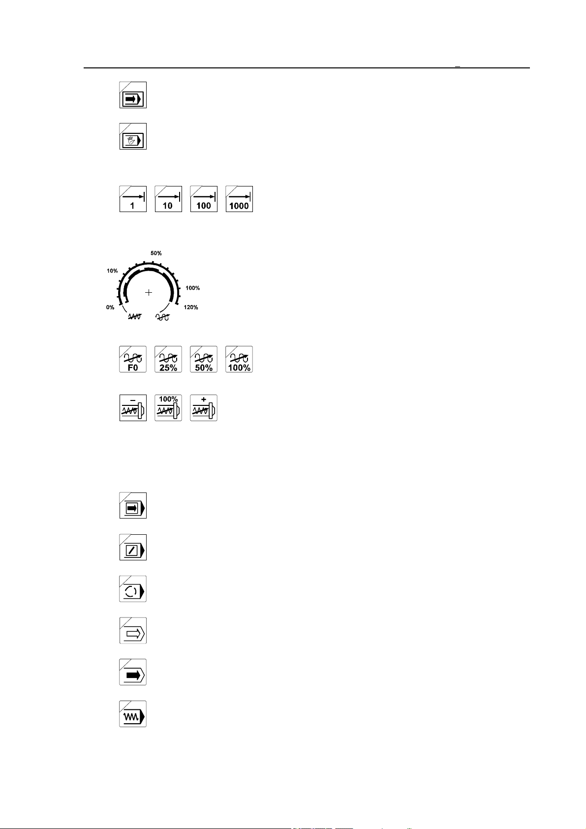
Automatic
Manual data input
Increment selectors:
Override switches:
1 Operator’s Panel
Selecting 1, 10, 100, 1000 increment size.
Feedrate override switch. By affecting it the programmed feedrate
can be changed in the 0-120% range.
Rapid traverse override value can be influenced by four
optionally supplied buttons.
Spindle speed override buttons. By affecting <–> the pro-
grammed revolution is reduced, by affecting <+> it is increased
by 10% in the 50-150% range. As the effect of button 100% the
programmed revolution is acknowledged.
Switches modifying the conditions of program execution:
Single block execution
Conditional block skip
Conditional stop
Program test
Machine lock
Dry run
15
Page 16
1 Operator’s Panel
Block restart
Block return
Function lock
Movement, start and stop buttons
Start button. Details of its functioning are discussed in the forthcoming
chapters of the Manual.
Stop button. Details of its functioning are discussed in the forthcoming
chapters of the Manual.
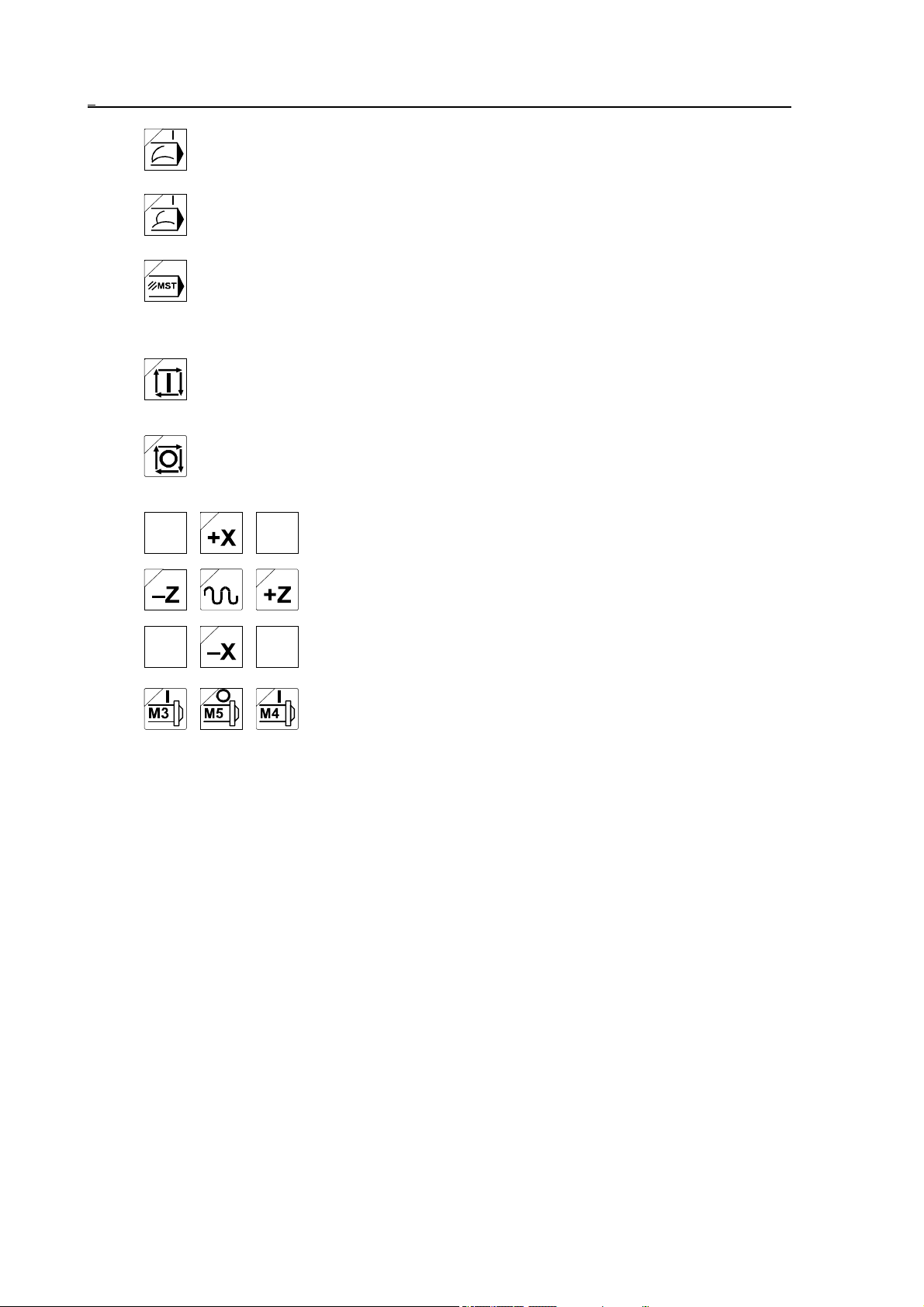
Jog buttons. Operators of jogging and incrementing. In case of
running to reference point they serve for selecting axes. The
arrangement of buttons can vary for machine types.
Spindle start and stop buttons. By affecting them the spindle
starts to spin in CW direction (M3), or in CCW direction (M4),
as well as stops to spin (M5).
Apart from these buttons the machine control panel contains 8 optionally used buttons
equipped with LEDs (with 4 optional rapid traverse override buttons among them), about
which the machine tool builder decides, what function he chooses to build in. Also, a manual
handle can be attached to the machine control panel.
16
Page 17
2 General Operating Knowledge
2 General Operating Knowledge
2.1 Screen Menu
After turning the power on among the captions interpreting the softkeys the screen menu is
active. On a color screen the default background color of the menu bar of the screen menu is
light grey. In order to switch over from another menu to this, the screen menu key
must be pressed. The different screens can be selected in the screen menu by pressing the
softkey with the appropriate caption. Actions (e.g., Data input) cannot be initiated from the
screen menu, this menu is only for to switch over between screens. The screen menu is of two
levels, in the first level the following screen menus can be found:
Position
If the appropriate screen within the screen menu is active, the caption of the menu field is
highlighted, otherwise the caption is dark (black). After turning the power on the ABSOLUTE
POSITION screen is active, this is why the Position (Positn) is highlighted. In order to switch
over to another screen menu simply the softkey of the desired screen menu must be pressed.
The last softkey of the first level of screen menu (beside the action menu key ) is the
Page. With this softkey can the next screen be switched over within the screen menu without
activating the menu by pushing the softkey of the active screen menu.
The control memorizes the screen within the screen menu, and when returning to the screen
menu it offers the same screen. For example: On the POSITION screen menu the MACHINE
POSITION is displayed by means of Page than after selecting the OPERATOR’S PANEL
screen menu the POSITION screen menu is returned, in this case the MACHINE POSITION
screen appears (the name of the screen can always be seen in the third line).
Should the control contain five softkeys (9" monitor), it can only display five menu fields at a
time. In this case the first level of the screen menu is as follows:
Position
Check2Program
1
Check
1
3
Program3Offsets
2
Offsets4Graphic
s5
Page
4
Setting6Service
5
Page
789
10
Note, that the fifth softkey is the Page!
The part containing the further screen menus can be displayed by pressing screen menu key
:
Graphics1Setting
Here the caption of neither screen menu is highlighted, for the POSITION screen menu is
active, but presently it is not shown. As the last screen menu is the SERVICE, by pressing
screen menu key again the previous part of the screen menu is returned. If there were
Service
2
Page
34
5
17
Page 18
2 General Operating Knowledge
further items after Service screen menu, those would be shown by pressing the screen menu
key , until the first part of screen menu is returned.
The number seen in the bottom right corner of menu field indicates the softkey number of the
appropriate menu field and not the line number of the menu within the screen menu (for more
see parameter SFNUMB ).
By pressing the softkey of the active screen menu, its menu appears. On the basis of the
previous example the following menu appears by pressing the Position softkey:
Absolute1Relative2Machine3End
Overall
4
5
The Position menu consists of five items, therefore starting with the sixth menu field the
forthcoming ones stay blank (for those have no meanings at all).
Suppose, that the second - and last - level of the screen menu is in effect. Here by pressing the
softkeys the caption of the appropriate menu field becomes highlighted and the selected screen
appears immediately. On the second level there is no Page softkey, because there the desired
screen can instantly be selected. If there is not enough room for the screens forming a screen
menu in the menu bar, the subsequent parts can be brought in by pressing the screen menu key
. If the last menu item of the screen menu is already in the menu bar, then by pressing
screen menu key the first level of the screen menu is returned.
The following menu items (screens) can be selected from the screen menus:
Position
Absolute1Relative2Machine3End
Overall5Cartesia
4
n6
7890
Check
Text
Function2Last
1
Active4Oprtr`s
3
panel 5
Message
6
7890
Program
Director
y1
View
2
Offsets
Work
offsets 1
Tool
offsets 2
Graphics
Graphic
Draw
param 1
18
Edit
3
W. offs.
measur 3
Block
input 4
T. leng.
measur 4
FEW
5 6 7 890
Rel. pos
offsets 5 6 7 8 9 0
2 3 45
6
7890
Page 19
Setting
#1-
#33 1
Service
#100#199 2
#500#599 3
Timer /
counter 4
Tool pot 5PLC ta-
ble 6
User’s
params7
2 General Operating Knowledge
Security
8 9 0
Param 1PLC
2
Test
I/O 3
Logic
anal 4
Test
mes 5
Scope
Errors 7Version
6
890
Summary: The screen menus are in two levels. The first level has eight screen menus. On the
first level the screens can be switched over within the active menu field by means of
Page softkey. If all menu items do not have enough room on the screen, the screen
menu key turns a page. If the last menu item is shown in the menu bar, then by
pressing screen menu key again, the first part of the first level is returned.
2.2 Action Menu
If some kind of action e.g., data input is to be done on different screens, the action menu
belonging to the screen can be switched over in the menu bar by pressing action menu key
. As could the screen menu, the action menu can also have maximum two levels, but in
some cases there are menu items already on the first level, that result in direct action.
The default background color of the action menu is orange. The active state of menu field may
also be indicated apart from the highlighted (white) or dark (black) colors of the caption by the
depressed state of menu field. If an action cannot be activated in the given control state, the
background color of menu field changes to the color of the screen menu and the menu field
serves no longer as a start button and is only surrounded by a frame.
If all action menu items belonging to the given screen do not have enough room in the menu
bar, then - as in case of screen menu - it is possible to turn the page within the menu by means
of action menu key . If the last menu is already on screen, then by pressing action
menu key the first part of the first level of the action menu is returned.
The action menu is determined by the active screen.
2.3 Data Input
On the different screens data input can be initiated. Data input must be started by pressing
action menu key The data input line is on the bottom of screen, above the softkeys is
the data input line, where the control gathers the entered data.
Numbers are entered according to the following rules:
– The number entered gives value to the address defined in the data input line.
– It is not mandatory to enter the left-hand (insignificant) zeros.
19
Page 20
2 General Operating Knowledge
– The digit entered is interpreted as an integer or as a decimal digit before or after the decimal
point has been pressed, respectively.
– It is not necessary to enter the right-hand insignificant zeros behind the decimal point or the
decimal point (in the case of an integer value).
– The data input can be started with decimal point when the integer part of a number is zero.
– Key and incremental operator I (provided they are permissible for the given address
character) may be hit several times during the input of the number, any time before the
use of arrow keys terminating the numeric input. The default is a positive absolute
value. The incremental data input and the sign will be indicated in the first and second
positions of the location in front of the number, respectively.
– The control system displays DATA error message during data input whenever a formal error
is committed in the number to be specified for the given address (exceeding the number
of integer or decimal digits, illegal use of the incremental operator or one of keys
or .
– A numeric input in progress can be cleared any time by key <DEL> before termina-
tion. In this case the condition preceding the commencement of numeric input is
restored.
The effects of keys and terminating a numeric input differ from each other in that
forward or backward stepping in the address chain will be performed upon depression of
or , respectively. Keys and can be used for stepping the address chain (in
the absence of a numeric input) as well as for the termination of a numeric input.
20
Page 21

3 General Displaying Areas and Actions Executed on Them
3 General Displaying Areas and Actions Executed on Them
Each general displaying area is accessible any time, independent of the current operation mode
or other states of control.
However actions belonging to the given display cannot be executed any time, the execution
can depend on the mode or other states of control. For example editing of parameters can only
be done in EDIT mode, although the list of parameters can be seen any time, in AUTOMATIC
mode even during machining . If execution of an action is impossible in the given control
mode, it is indicated by two arrows pointing at each other º» (conflicting state) in the status
field of the seventh message line.
It is quite another matter, that the action may be able to be executed in any control mode, still
the action will not be effective immediately. For example the tool offset value can be changed
any time, even during milling, yet the machining must be interr upted (create INTD state) and
restarted for the control to register the new offset value.
21
Page 22
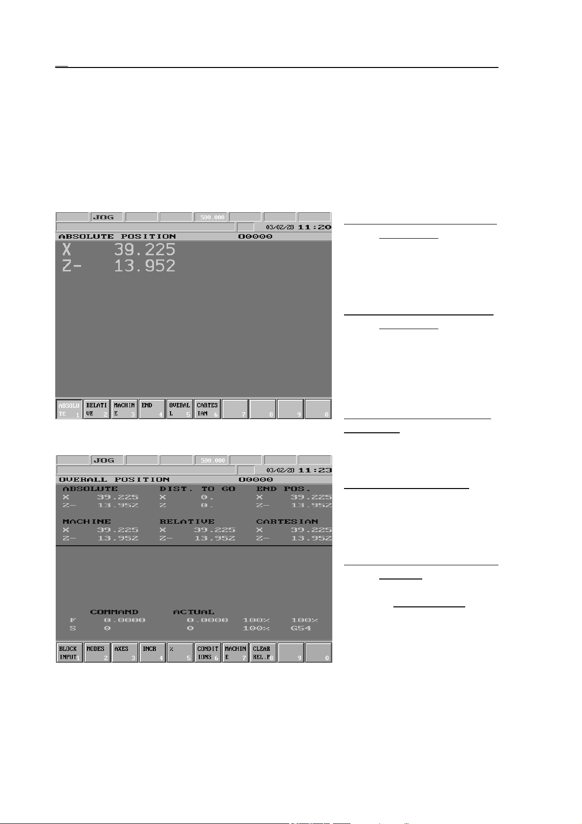
3.1 POSITION Screens
3.1 POSITION Screens
There can be five types of POSITION screens. The first four screens displays the selected
position with big-size characters, meanwhile on the fifth screen all position displays as well as
in case of six or fewer axes the feed and revolution values are also displayed with normal
characters. In case of an oriented spindle when the loop is closed (state M19) the screen shows
the angle position of the spindle instead of the revolution. If the spindle can be programmed as
axis C, the line starts with C in place of S. In the line of feed display the current coordinate
system number can also be read.
ABSOLUTE POSITION Scre-
en (Absolt): In the
selected coordinate
system in respect of the
appropriate offsets and
compensations.
RELATIVE POSITION Scre-
en (Relatv): After refer-
ence point has been returned it corresponds to
absolute position. It can
be overwritten or zeroed
in an optional state.
in the G53 coordinate system in respect of length offsets.
MACHINE POSITION Screen (Mach): Position measured
END POSITION Screen: End
position of the block in
the current coordinate
system in respect of
length offsets.
OVERALL POSITION Screen
(Overll): Beside the
previous four displays
the distance to go also
gets to be displayed. It
shows how much is left
of the current movement.
By this display (in case of
six or fewer axes) the
programmed and current
feed and revolution can
also be seen.
22
Page 23

3.1 POSITION Screens
CARTESIAN POSITION Screen: In the state of polar coordinate interpolation on (G12.1) it
indicates the tool position in the programmed Cart esian coordinate system. In the state
of polar coordinate interpolation off (G13.1) positions indicated here are the same as
on the screen ABSOLUTE.
The first three screens also have a setting function; The position display selected the last time
will be beside distance to go and end position by general displaying areas (except for offsets),
where the position display can be seen on the top of general displaying area.
Actions of POSITION Screens
Actions of POSITION screens correspond to that of the OPERATOR’S PANEL screen (see
the chapter 3.2.4).
23
Page 24

3.2 CHECK Screens
3.2 CHECK Screens
This screen serves for displaying running programs and their states.
3.2.1 PROGRAM TEXT Screen, Listing of Running Program
In the lower part of general displaying area the list of the running program can be seen. One
block on the list is highlighted;
This is the block under execution. In the middle part of general displaying areas of feed and
revolution can be seen (provided
the number of displayed axes is
not more than six). The position
display is in the upper part of
general displaying area. In the
first column the current tool position in agreement with the selected POSITION screen (see
the chapter 3.1), in the middle
column the distance to go position, while in the right one t he end position can be seen.
3.2.2 FUNCTION Screen, Subprogram and Macro Levels
In the right-side subprogram
field of general displaying area
the active subprogram(s) can be
seen. Directly after the number
of the subprogram stands the
repetition number. The fields on
the bottom of general displaying
area show information on the
revolution state of spindle (M3,
M4, M5, M19), of the gear
range (M11, M12, M113,
M14,...), of the current tool
(Tnnnn), of auxiliary functions
(A, B and C), as well as of
further (in PLC program
defined) M codes.
The first column shows the position in agreement with the selected POSITION screen (see the
chapter 3.2), while the second one shows the distance to go position.
24
Page 25
3.2 CHECK Screens
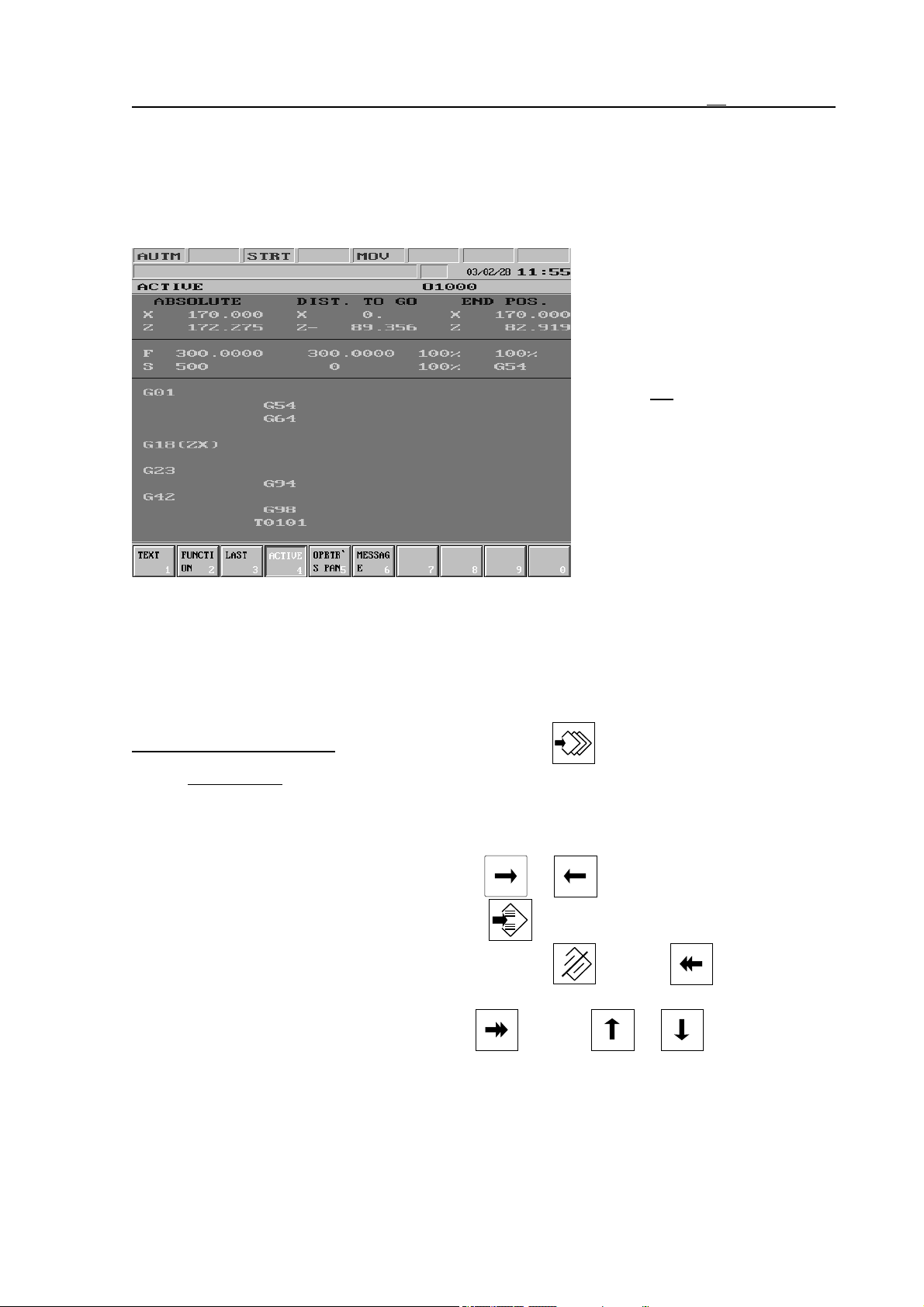
3.2.3 LAST and ACTIVE screens. G Codes and Compensations.
On the LAST and ACTIVE screens the active G codes and compensations under block
display (LAST) and program execution (ACTIVE) can be seen. The LAST screen corresponds
to the values of #4000..., #4100... macro variables, while the ACTIVE screen to that of
#4200..., #4300... .
The current tool position is
displayed on the upper part of
general displaying area. In the
first column the position in
agreement with the selected
POSITION screen (see the
chapter 3.1), in the middle
column the distance to go
position, while in the right one
the end position can be seen.
If less than seven axes are to be
displayed information on feed
and spindle revolution appears in
the middle part of general
displaying area.
In the lower part of general
displaying area starting from the left, downwards the G codes and the tool number with the
compensation number can be seen.
Of the G codes only those, different from default setting are displayed.
Actions of sreens PROGRAM TEXT, FUNCTION, LAST and ACTIVE.
Block Input action menu: Pushing action menu button and selecting action menu
Block Input, it is possible to input and execute a program block or to modify an old
one. Block Input and execution is only available in modes jog (JOG), incremental jog
(INCR) or handle (HNDL).
The block demanded can be edited by the alphanumerical keys. In the line has been
edited cursor can be moved by the keys or if something is to be over-
written or deleted. For insertion use key INS. By pushing it INSERT and
OVERWRITE state can be toggled. Use buttons DEL, or (Backspace)
for deletion.
Block input can be terminated by keys (Enter), or . Then in status
field 2 the title (SBEX) (single block execution) appears. Using START button the
single block is executed. With RESET key single block exetution can be cancelled
(even before pushing START) and the block can be edited again. Single block in buffer
is saved and can be recalled until turning the control off.
25
Page 26
3.2 CHECK Screens
Action I can be used for input of incremental operator. Action Block Delete clears the
whole block in buffer.
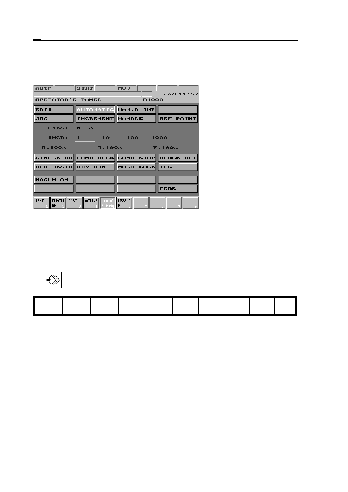
3.2.4 OPERATOR’S PANEL Screen
The general display area of OPERATOR’S PANEL shows a
view on the state of the most
essential machine control items.
The controllability of different
item groups from softkeys is
permitted by the PLC program.
The illustration shows the general displaying area of the control panel.
In the topmost button group the
state of operation mode switches
can be seen. Below it the state of
axis selecting switch is shown.
This is followed by the incre-
ment selecting switch, than in
the third line the percent switches are displayed.
The button group in the middle reflects the state of condition switches and the one below that
of PLC switches.
Actions of OPERATOR’S PANEL Screen
The following actions can be activated on Operator’s Panel screen by pressing action menu
key :
Modes
1
Axes
2
Incr
%
3
Conditio
4
ns 5
Mach6Clear
rel.pnt.7 8 9 0
The first six keys are menu keys, i.e. by pressing the appropriate softkey the action keys
belonging to the given menu become visible. On the menu field of action keys, if the appropriate softkey is pressed and the control accepts it the key stays depressed. The seventh CLEAR
RELPNT is an action key, i.e. its pressing results in an immediate effect.
The controllability of each action menu from softkeys is permitted or prohibited by the PLC
program. If an action cannot be controlled from softkeys, it can be accessed from an external
control device. Instruction regarding this can be found in the enclosed manual of the machine.
26
Page 27
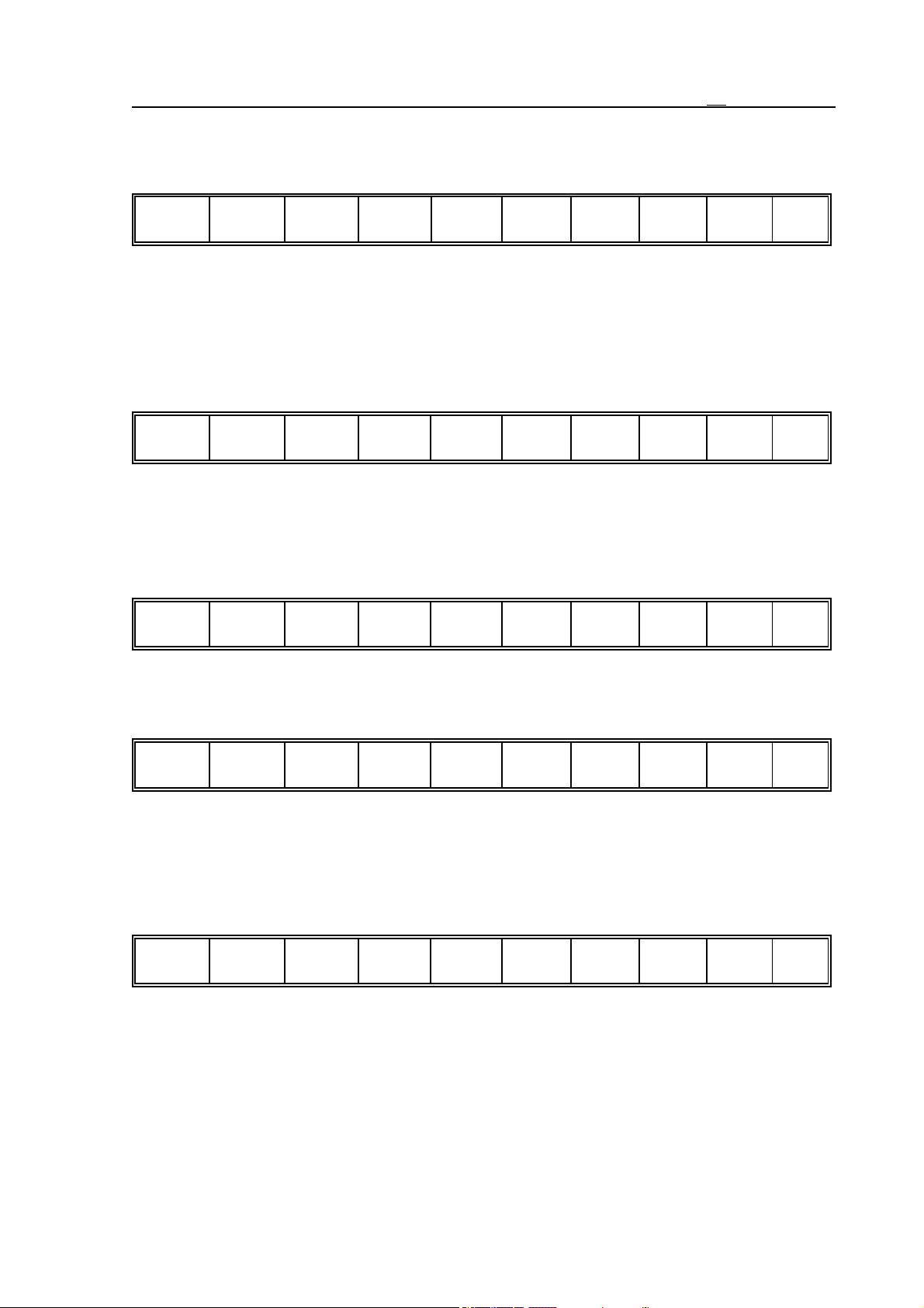
Operation Modes Actions (Modes)
The following modes can be selected:
3.2 CHECK Screens
Edit
1
Auto
2
Mdi
Jog
3
4
Incr
Handle
5
6
Ref
7890
Axes Actions
In the menu bar all axes of the machine tool are listed. Here t he axis, with which an action
must be done, can be selected. This action is necessary for example if an axis is to be moved by
means of a manual handle. The axis to be moved must be selected by the use of the appropriate
softkey In this case a highlighted frame surrounds the letter indicating the selected one in the
Axis line of general displaying area.
X
Y
1
Z
2
B
3
4567890
Increment Actions (Incr)
In the menu bar the eligible increment sizes are listed. If one is selected, it is surrounded by a
highlighted frame. The selected increment has function in the Incremental feed (INCR) and
Manual handle feed (HNDL) modes. The values seen in the menu bar are in increments.
1
10
1
2
100
3
1000
4567890
% Actions
The rapid traverse, spindle and feedrate switches can be modified by pressing softkeys.
R-
R+
1
S-
2
S+
3
F-
4
F+
5
67890
The current position of switches can be seen in the middle of general displaying area at
addresses G, S and F.
Conditions Actions
The following states can be switched on or off:
Single
block 1
Cond.
block 2
Cond.
stop 3
Block
return 4
Block
restart 5
Dry run6Machin
e lock 7
Test
890
Machine Actions (Mach)
Maximum eight optionally used softkeys. Their captions are determined by the PLC program,
about their operation and usage instructions can be read in the enclosed manual of the machine.
Provided the :197 module of PLC program does not contain the caption of keys, the PLC1,
PLC2 ... PLC8 is set automatically.
27
Page 28

3.2 CHECK Screens
Clear Relative Position Actions (Clear Relpnt)
The relative coordinate displays can be zeroed by means of action keys. Relative position
setting by axes is discussed in the chapter 3.4.5.
3.2.5 MESSAGES Screen
In this general displaying area the momentary messages in wait ing state can be seen. As in the
2nd field of the status bar only the active message (waiting for intervention) can be read, this
general displaying area shows, whether there are any other messages at the moment apart from
those seen in status bar, that due to this cannot be displayed.
28
Page 29
3.3 PROGRAM Screens
3.3 PROGRAM Screens
Screens of actions executed on part programs.
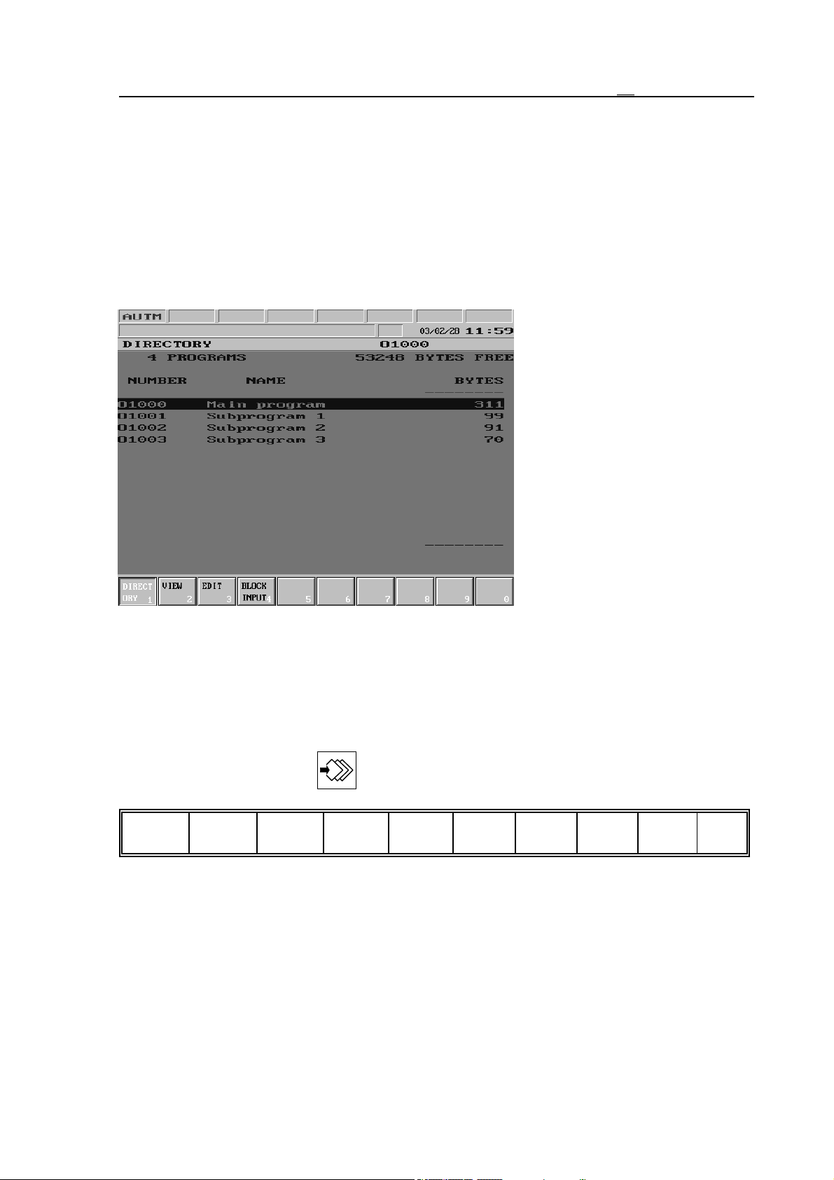
3.3.1 DIRECTORY Screen
In the top line of general displaying area the number of programs in memory and the free
memory in bytes can be seen.
The programs in memory are listed in the middle part. The control records the programs
according to their code; These
numbers can be read in the first
column. In the middle column
may be the name of program (it
is not obligatory to name the
program, therefore this column
may be here and there blank).
The last column contains the
program length in bytes. If above
or below the last column arrows
can be seen, this means, that the
entire list does not have enough
room in the general displaying
area and in the direction of the
arrow further programs can be
found.
On the list a highlighting bar can
be moved by means of arrow
keys. This highlighting bar enables to select the program with which an action needs to be
done.
Actions of DIRECTORY Screen
The following actions and action menus can be activated to the DIRECTORY screen by means
of pressing action menu key :
New
Search2Delete3Load
1
4
Save
5
Run
Restore7Sort
6
Protect
8
90
29
Page 30
3.3 PROGRAM Screens
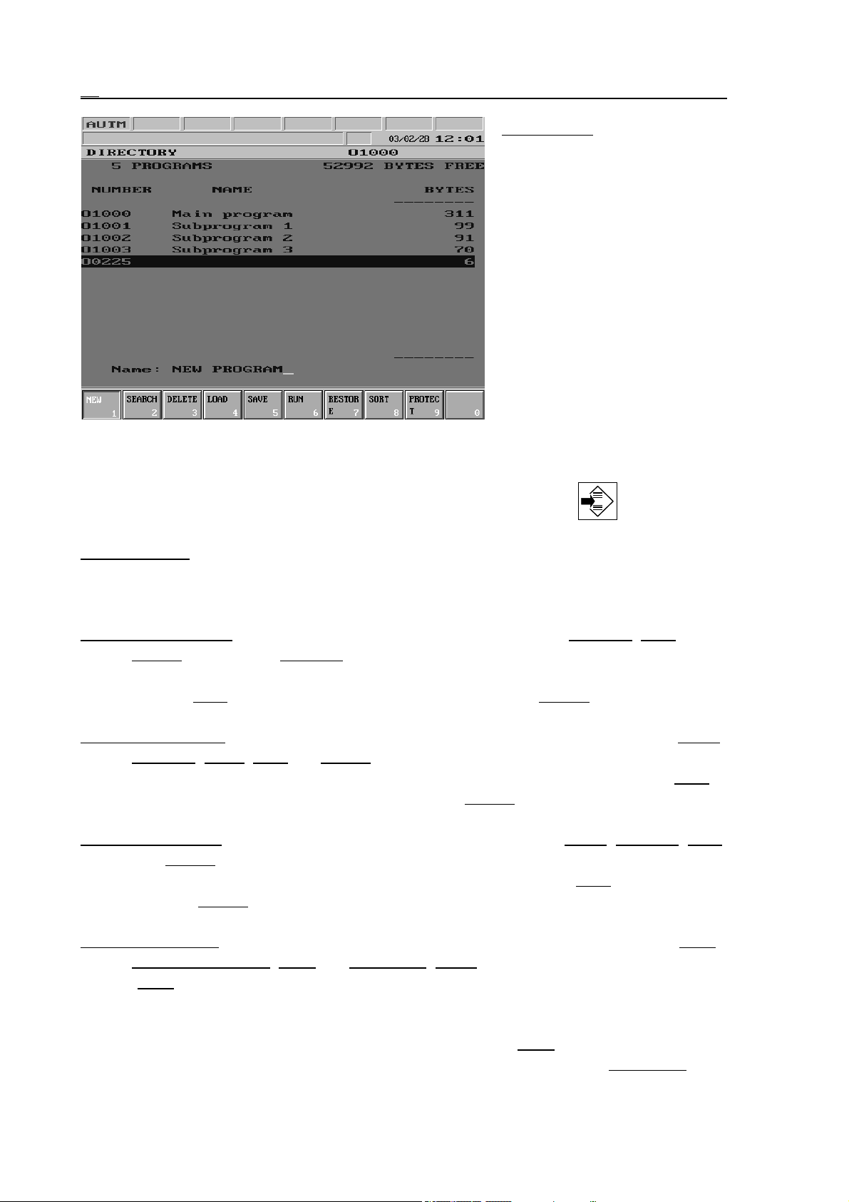
New Action: When pressing the
softkey a window opens
in the bottom left part of
general displaying area,
where the program number can be typed in. The
input can be terminated
by any arrow key. In this
case a new program occurs with the number
entered, or an error message is displayed, if there
is already a program with
the same number or if
there is no room in the
memory.
If the program number input is terminated by the arrow pointing to the right, the name of the
program can also be specified here. When typing a name, switch-over between normal and
capital letters can be done by means of page keys, while by pressing INS , and ', :, " or !
accented or special characters can be entered.
Search Action: After pressing the softkey a program number can be entered into the window
in the bottom left corner of general displaying area. By terminating number input by
means of any arrow key the highlighting bar goes to the registered program, or an error
message is displayed, if there is no program with the entered number in the memory.
Delete Action Menu: By pressing the key another three actions occur: Ramdisc, Exec,
Cancel. By means of Ramdisc key it can be decided, whether the programs in memory
or the programs of NCT90RD unit connected to the control are to be deleted. As the
effect of Exec the action is executed, while with the help of Cancel the action can be
canceled; in this case the first level of the action menu is displayed.
Load Action Menu: By pressing the key the following actions appear in the menu bar: Serial,
Ramdisc, Prom, Exec and Cancel. By means of the first three switches it can be set,
from where is the program to be loaded in the control memory. As the effect of Exec
the loading process starts, while with the help of Cancel the first level of action menu
can be displayed.
SSave Action Menu:
By pressing the key the following actions appear: Serial, Ramdisc, Exec
and Cancel. By means of the first two switches it can be set, where to is/are the
selected program(s) to be saved. The saving process starts as the Exec key is affected,
while the Cancel key displays the first level of action menu, this way canceling the
action.
Run Action Menu: By pressing the key the following softkeys appear in the menu bar: Auto,
Manual data input, DNC and DNC NCT, Table. By means of the first softkey
(Auto) the program can be selected for automatic operation. The key is ineffective, if
the control is in automatic mode and state INTD, STRT or STOP is in effect. With the
help of the second action key the program of manual data input mode can be selected.
The last two action keys determine the DNC mode. The DNC key switches over the
control to simple DNC mode without protocol, while with the help of DNC NCT key
30
Page 31
3.3 PROGRAM Screens
DNC contact working on the basis of DNC protocol can be implemented. The Chart
action is only effective in Edit mode. By pressing it, provided program No. T (tool pot
table) or P (PLC table) is highlighted, the file containing the selected chart is loaded to
the appropriate chart. See the chapter 3.6.5 “TOOL POT TABLE” and the chapter
3.6.6 “PLC TABLE”. Using key DNC FEW programs can be executed from PC
optionally integrated into the control.
Restore Action Menu: When pressing the softkey the deleted files, that are still in the control
memory and can be totally undeleted are displayed in the general displaying area. By
moving the highlighting bar to the appropriate program the selected file can be reapplied with the help of Exec action.
Sort Action Menu: The sorting of programs found in directory in the - by softkeys - selected
aspect can be implemented. Within the sort action menu the following softkeys exist:
Incrsg (increasing), Decrsg (decreasing). the sorting direction, as well as Selected
(selected), Type, Size (byte) and Number for selecting the sorting aspect. As the
effect of Exec
the action is executed.
Protected Action: As the effect of the action the protected attribute of the selected file(s) can
be switched on or off.
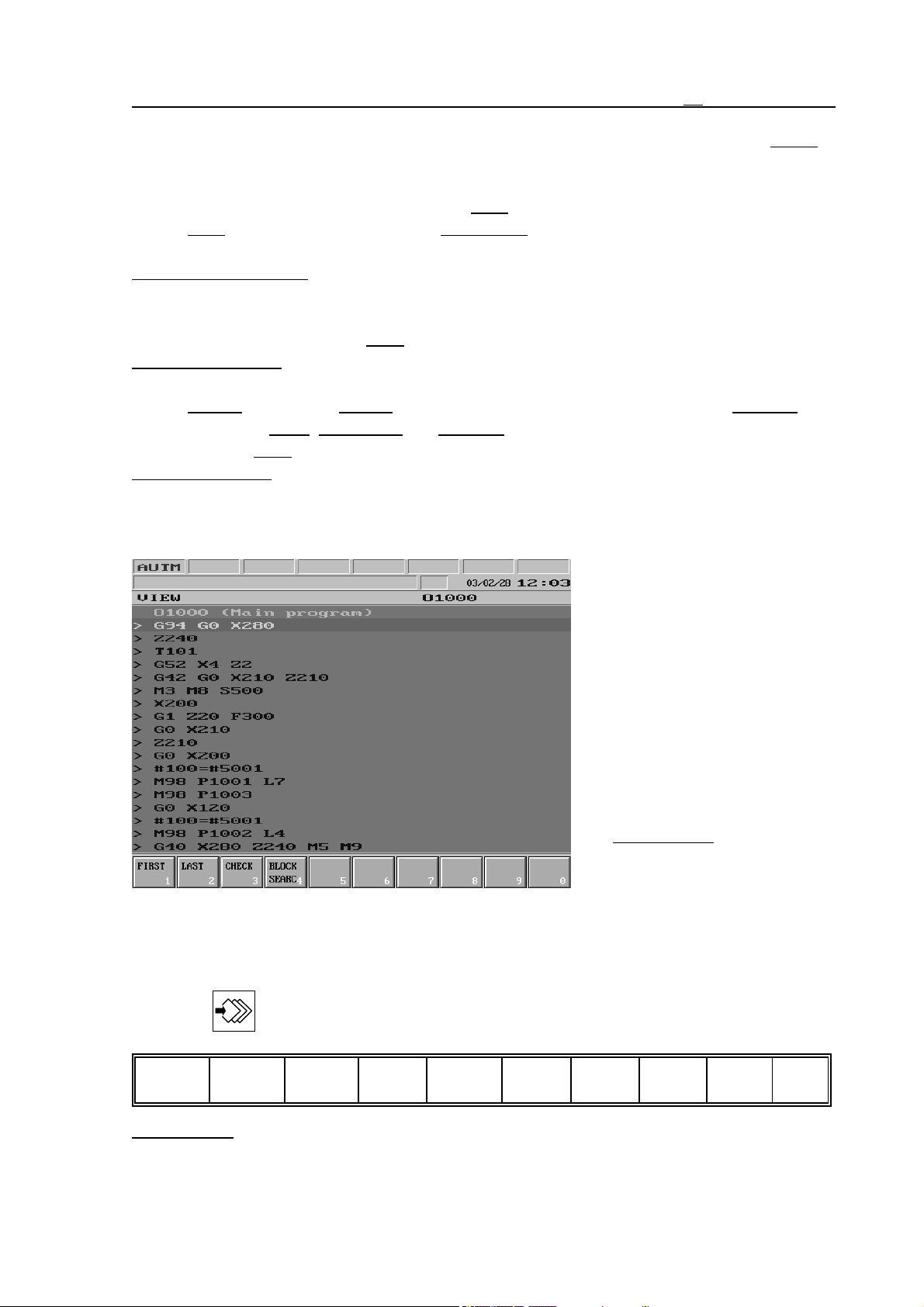
3.3.2 VIEW Screen
In the general displaying area the
list of the program selected on
DIRECTORY screen, can be
seen. The number and name of
the program can always be seen
in the topmost line. A highlighting bar can be moved on the
program, which highlights one
block at a t ime. The highlighting
bar can be moved by arrow and
page keys.
The highlighting bar has function
by Block search actions. There
the bar is also a means of
selecting the block from which
the machining is to be continued.
Actions of VIEW Screen
On the VIEW screen the following actions and action menus are at disposal, after the action
menu key is pressed:
First
Last
1
First Action:
gram.
Check3Block
2
search 4 5 6 7 8 9 0
When pressing the key the highlighting bar goes to the first block of the pro-
31
Page 32
3.3 PROGRAM Screens
Last Action: When pressing the key the highlighting bar goes to the last block of the program.
Check Action: When pressing the key control brings the highlighting bar to the last block of
the program, meanwhile it reads the entire program and examines its check sum. This
way it checks if the program in memory is damaged (the program can be damaged for
example due to storage or operation in too low temperature).
Block Search Action Menu: When pressing the key the following actions occur: First, Last,
Exec, Go, Interrupted and Cancel. For description of the search actions see the
chapter 13.6 “Automatic Operation Start after Block Search” on the page 117.
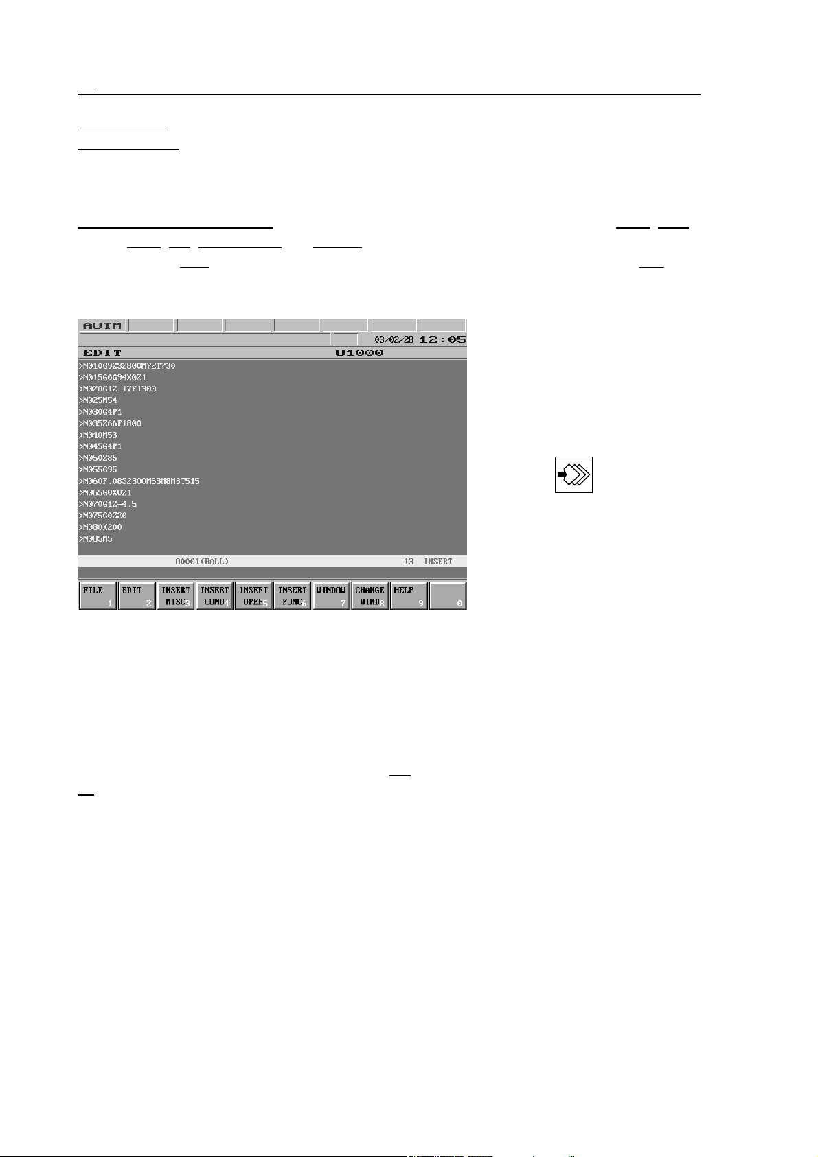
3.3.3 EDIT Screen
In the general displaying area the
list of an editable program can
be seen. The number and name
of a program can always be read
in the first line of the area.
It is possible to write or modify
the program by pressing action
menu key . Modification
of protected programs is not
possible. If EDIT mode is active
and no program execution is
interrupted (INTD), the selected
main program is displayed on
Directory screen, while if execu-
tion is interrupted it is the
program, in which the line under execution can be found. In case the control is not in EDIT
mode, or the second window is opened, the program selected on Directory general displaying
area is displayed. If execution is not in INTD state modification of running program is not
permitted.
Actions of EDIT Screen
For description of EDIT screen see the chapter 4.4 “Actions of EDIT Screen” on the page
.
62
32
Page 33
3.3 PROGRAM Screens
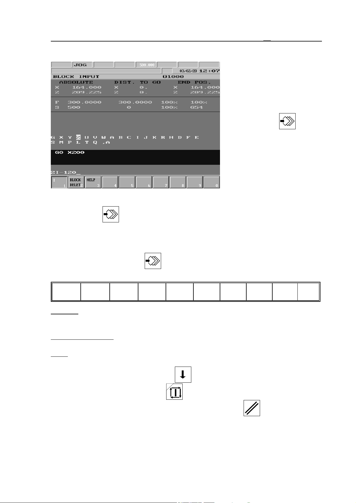
3.3.4 BLOCK INPUT Screen
In the upper part of general
displaying area the current position can be seen. It is possible to
enter single block as well as to
re-execute or to modify a block
entered earlier on by pressing
action menu key . A sing-
le block is to be entered similarly
to that of a program block, however in the address chain of the
single block the address letters,
of which the entering would be
here senseless are automatically
not specified. Entering single
block is only possible in jog
(JOG), incremental jog (INCR), or manual handle feed (HNDL) mode, otherwise by pressing
action menu key the address chain does not even show up.
Actions of BLOCK INPUT Screen
After pressing action menu key the following actions are available to the BLOCK
INPUT screen:
I
Block
1
delete 2
Help
34567890
I Action: The key makes it possible to switch the I (incremental) operator on and off on the
current address letter. When executing a letter I shows up directly after the coordinate
address.
Block Delete Action: The key serves for deleting a block in the single block buffer (that has
been written in earlier on).
Help: if the cursor stands on a G function and softkey Help is pressed, than the illustration of
the G code execution is drawn on screen.
The single block is to be terminated by key . In this case caption SBEX occurs in the 2
nd
field of status bar. By affecting START button the single block is executed. The
execution of a single block can be interrupted by means of RESET key (even before
pressing the START button), this way the previous block can be re-edited. The block in the
buffer is kept until the power is turned off.
33
Page 34
3.4 OFFSETS Screens
3.4 OFFSETS Screens
Screens of actions executed on zero point and offset registers.
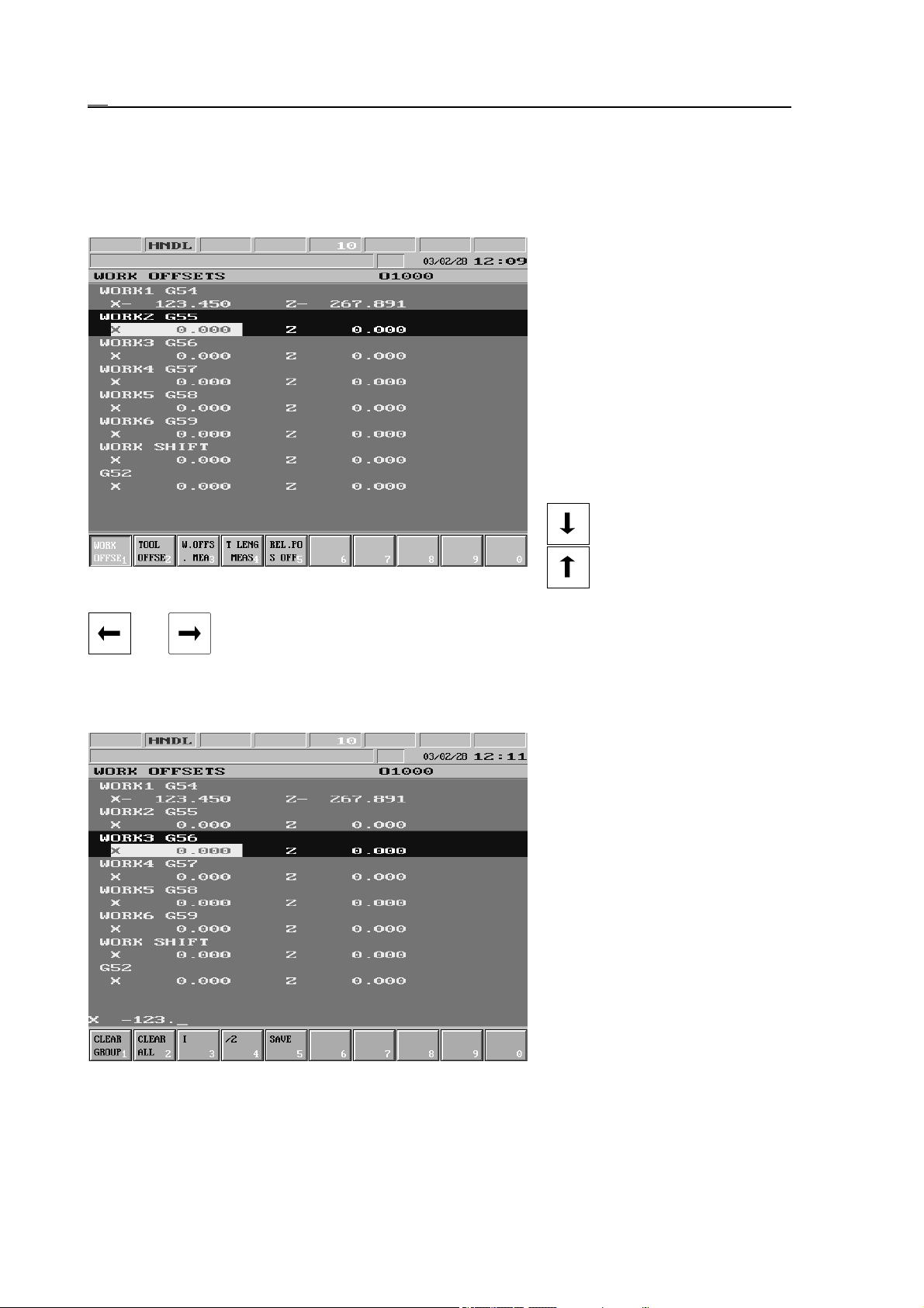
3.4.1 WORK OFFSETS Screen
In the general displaying area are
offset values of G54, ..., G58,
common zero point offsets, as
well as of offsets programmed
by means of commands G52 and
G92. The coordinate values
belonging to one zero point form
a group. Along the groups the
highlighting bar can be moved
forward (in the direction of
increasing coordinate system
numbers) with the help of key
and backward with key
. Within the highlighting
bar indicating the coordinate system the inverse bar on axis addresses can be moved with keys
and . This bar makes it possible to select the wished axis within the coordinate
system.
Actions of WORK OFFSETS Screen
Actions executed on WORK
OFFSETS screen overwrite off-
set registers immediately, how-
ever this is registered by the pro-
gram under execution only in
case the program has been start-
ed from the beginning or the
program execution is interrupted
(INTD state) and afterwards re-
started. So the current
coordinate system is overwritten
in vain, the modified value will
not be registered till the modified
coordinate system is not used by
the system. It also follows, that
hasty overwrite of the coordinate system will not cause immediate problem during program execution, its effect may only be
perceptible in case of the next running of program, so when overwriting it be extremely
cautious. To the WORK OFFSETS screen the following actions and action menus can be
34
Page 35
activated by pressing action menu key :
3.4 OFFSETS Screens
Clear
group 1
Clear
all 2
I
/2
3
4
Save
567890
Clear Group Action Menu: When pressing the key the question CLEAR G5x? (G5x
according to current coordinate system) appears in the bottom left part of general
displaying area, together with Exec and Cancel actions in menu bar, the meaning of
which is the usual.
Clear All Action Menu: When pressing the key the question CLEAR ALL? Occurs in the
bottom left part of general displaying area, together with Exec and Cancel actions in
menu bar, the meaning of which is the usual.
I Action: The key enables switching of I (incremental) operator on and off on the current
address letter. During the execution letter I appears directly after the coordinate
address. The value entered will be added to the original offset value.
/2 Action: It halves value written on the current address letter. After execution half of the
value in the coordinate address can be seen.
Save Action: When pressing the key the program number can be entered into the bottom data
input line. In case the input is terminated by any of the keys or , the
program can also be named there. As the effect of keys and the offset
values are saved in the appropriate macro variable. If in such way saved offset values
need to be reset, the program must be selected for automatic execution and executed in
automatic operation.
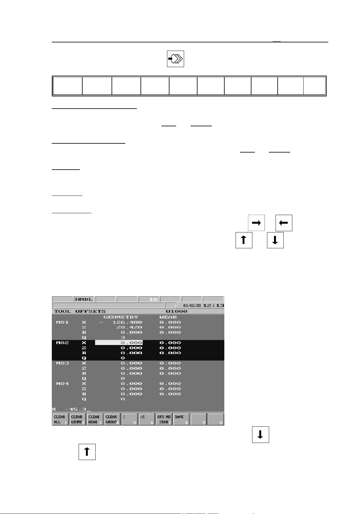
3.4.2 TOOL OFFSETS Screen
In the general displaying area the
values of tool offsets in X, Z
(optionally Y) directions as well
as the tool nose radius compensation value and the imaginary
tool nose number at address Q
can be seen. The offset registers
with identical number form a
group. The real offset value is
specified by the signed sum of
geometry and wear values.
Along the groups the highlighting bar can be moved forward
(in the direction of increasing
register numbers) with the help
of key , while backward
with key . Within the highlighting bar indicating a group an inverse bar can be moved by
35
Page 36
3.4 OFFSETS Screens
keys and . This bar selects the offset register to be modified.
Actions of TOOL OFFSETS Screen
Actions executed on TOOL OFFSETS screen overwrite offset registers instantly, however it is
registered by the program under execution only if the program has been started from the
beginning or the program execution is interrupted (INTD state) and restarted. So the current
offset is overwritten in vain, the modified value will not be registered till the modified values
are not called by the system. It also follows, that hasty overwrite of offsets during program
execution will not cause an immediate problem, its effect may only be perceptible in case of the
next running of the program, so when modifying be extremely cautious.
The following actions and action menus can be activated to the TOOL OFFSETS screen by
pressing action menu key :
Clear all1 Clear
geomtry2
Clear
wear 3
Clear
group 4
I
/2
5
Ofs No
6
search 7
Save
890
Clear All Action Menu: When pressing the key the question CLEAR ALL? can be read in
the bottom left part of general displaying area, together with Exec and Cancel actions
in menu bar, the meaning of which is the usual.
Clear Geometry Action Menu: When pressing the key the question CLEAR ALL
GEOMETRIES? can be seen in the bottom left part of general displaying area,
together with Exec and Cancel actions in menu bar, the meaning of which is the usual.
Clear Wear Action Menu: When pressing the key the question CLEAR ALL WEARS? can
be seen in the bottom left part of general displaying area, together with Exec and
Cancel actions in menu bar, the meaning of which is the usual.
Clear Group Action Menu: When pressing the key the question CLEAR THIS GROUP?
can be seen in the bottom left part of general displaying area, together with Exec and
Cancel actions in menu bar, the meaning of which is the usual.
I Action:
The key enables switching of I (incremental) operator on and off on the current
address letter. During the execution letter I appears directly after the coordinate
address. The value entered will be added to the original offset.
/2 Action: It halves value written on the current address letter. After execution half of the
value in the coordinate address can be seen.
Offset Number Search Action:
When pressing address N occurs in bottom data input line.
After the value has been entered and terminated (by any of the arrow keys) it searches
for the entered offset group in the memory.
Save Action: When pressing the key an O program number can be entered into the bottom
36
data input line. In case the input is terminated by any of the keys or , the
program can also be named there. As the effect of keys and the offset
values are saved in the appropriate macro variable. If in such way saved offset values
need to be reset, the program must be selected for automatic execution and executed in
automatic operation.
Page 37
3.4 OFFSETS Screens
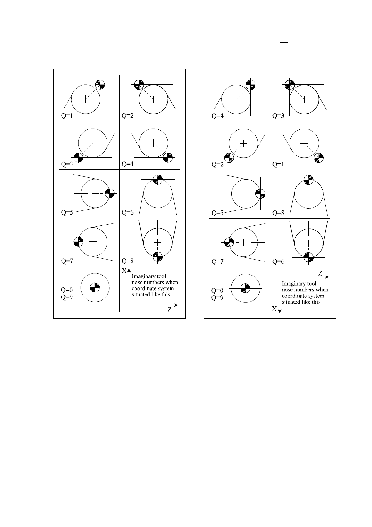
On the figures below the interpretation of the imaginary tool nose number (Q) can be seen.
37
Page 38
3.4 OFFSETS Screens
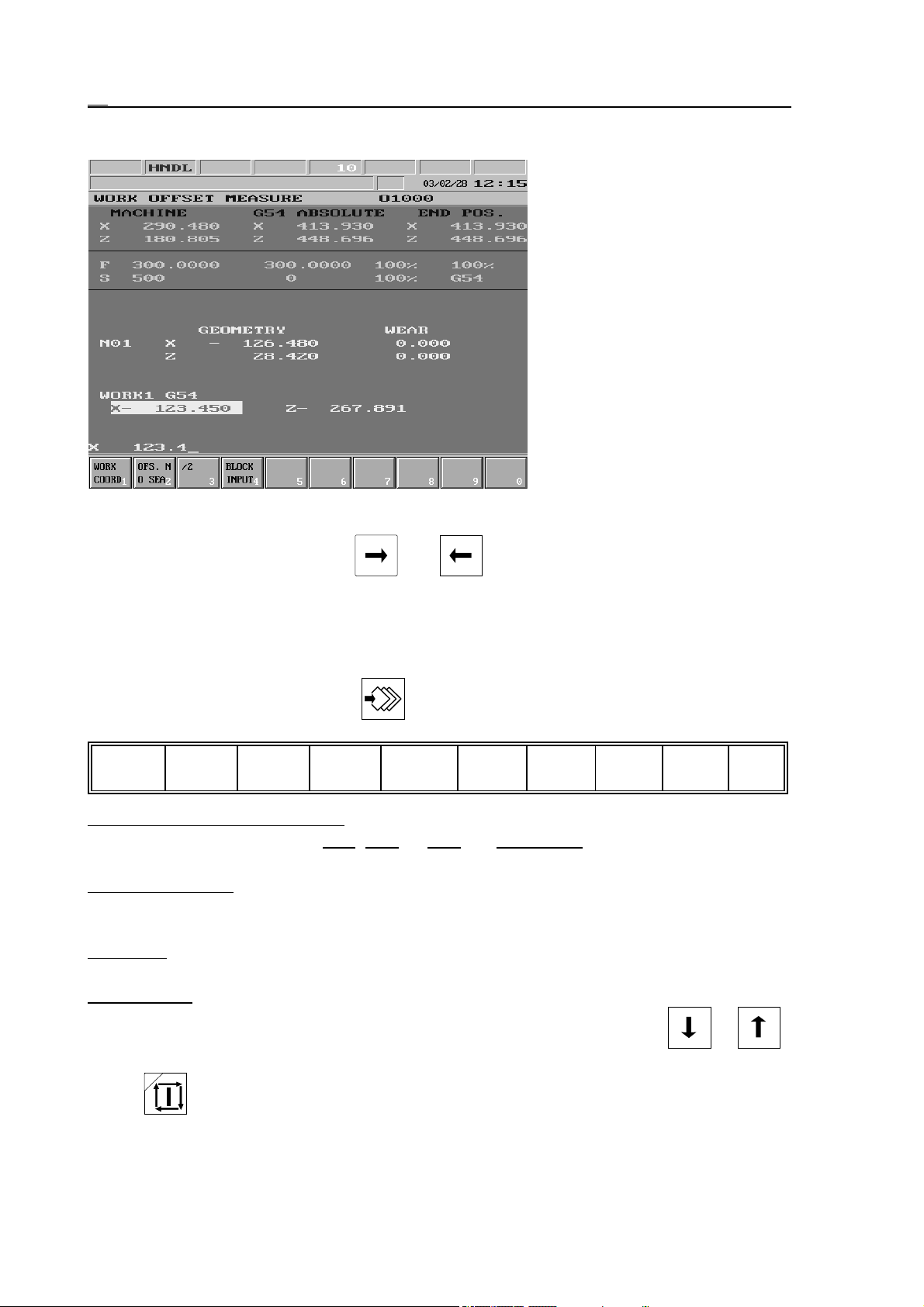
3.4.3 WORK OFFSET MEASURE Screen
In the upper part of general
displaying area the current tool
position can be seen. The first
column always shows the
machine position, the middle
column the posit ion in the
selected coordinate system,
while the last one the distance to
go position. The following information can be seen in the lower
part of general displaying area
going downwards. In line Nnn
the length offset values of the
indicated offset group can be
seen for each axis. In the next
line stands the number of the se-
lected coordinate system, and below its offset registers. Along the offset registers highlighting
bar can be moved by means of keys and . This highlighting bar enables to select
the offset register to be modified.
Actions of WORK OFFSET MEASURE Screen
The following actions and action menus can be activated to the WORK OFFSET MEASURE
screen by pressing action menu key :
Work
coordnt1
Work Coordinate Action Menu:
Ofs No
search 2
/2
Single
3
block 4 5 6 7 8 9 0
appear in the menu bar: G54
When pressing the key the eligible coordinate systems
, G55, ... G59 and Work shift. After pressing the
appropriate softkey the system returns to first level of action menu.
Offset No. Search: When pressing the key letter N appears in spite of the axis address. At this
point the number of offset the register can be entered. After entering the offset number
the desired length offset register can be seen in general displaying area.
/2 Action: It halves value written on the current address letter. During execution half of the
value in the coordinate address can be seen in input field.
Single Block: By pressing the key a single block can be entered in the bottom, data input line
38
by the use of the alphanumeric keyboard. After closing block edit (key or )
caption SBEX appears in the 2nd field of status bar. The block is executed with START
.
Page 39
3.4 OFFSETS Screens
For detailed description of work offset measure see the chapter 7.2.1 “Work Offset Mea-
sure” on the page 76.
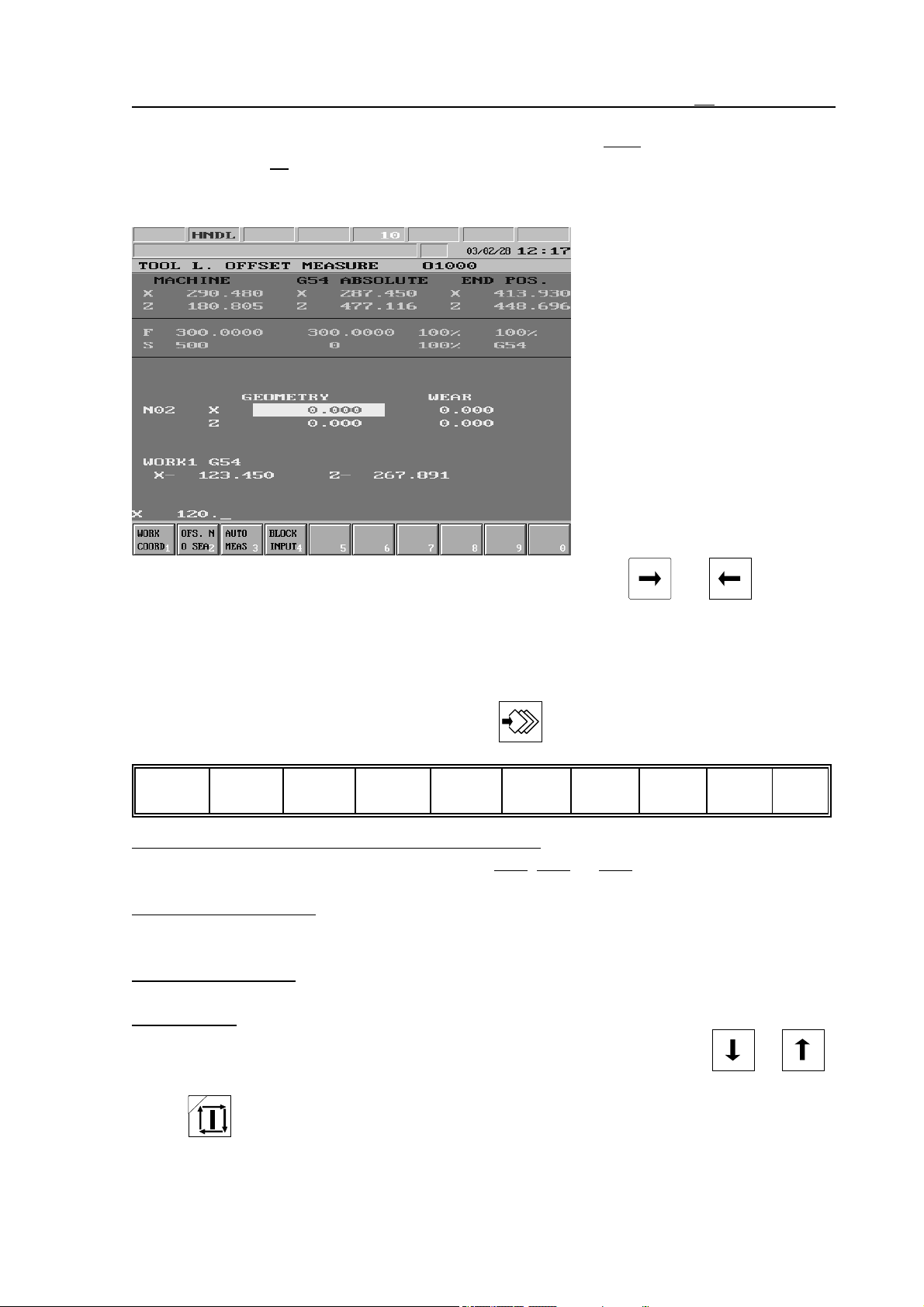
3.4.4 TOOL LENGTH OFFSET MEASURE Screen
In the upper part of general
displaying area the position display can be seen. The following
information can be seen in the
lower part of general displaying
area going downwards. In line
Nnn the length offset values of
the indicated offset group can be
seen for each axis. In the next
line stands the number of the
selected coordinate system, and
below its offset registers. A
highlighting bar can be moved
along the axis addresses of length offset register by means of
keys and .
Actions of TOOL LENGTH OFFSET MEASURE Screen
The following actions and action menus can be activated to the TOOL LENGTH OFFSET
MEASURE screen by pressing action menu key :
Work
coordnt1
Work Coordinate System Action Menu (Work cld):
Ofs No
search 2
Auto
meas 3
Single
block 4 5 6 7 8 9 0
When pressing the key the eligible coordinate systems appear in the menu bar: G54, G55, ... G59. After pressing the
appropriate softkey the system returns to first level of action menu.
Offset Number Search: When pressing the key the letter N appears in spite of the axis
address. At this point the number of the offset register can be entered. After entering
the offset index the desired length offset register can be seen.
Automatic Measure: The function can only be used provided the machine is mounted with a
tool length sensor.
Single Block: By pressing the key a single block can be entered in the bottom, data input line
by the use of the alphanumeric keyboard. After closing block edit (key or )
caption SBEX appears in the 2nd field of status bar. The block is executed with START
.
39
Page 40
3.4 OFFSETS Screens
For detailed description of work offset measure see the chapter 7.2.2 “Tool Length Offset
Measure inside the Machine” on the page 79.
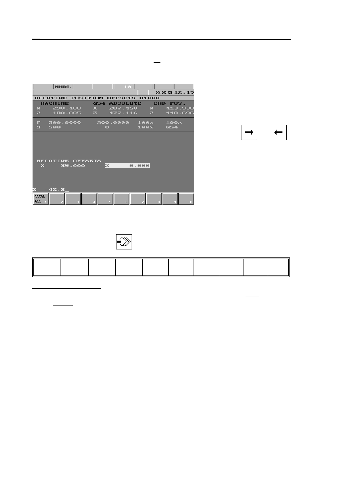
3.4.5 RELATIVE POSITION OFFSETS Screen
In the general displaying area
below the current tool position
are the values of relative position
offsets. An inverse bar can be
moved on axis addresses by
means of keys and .
This bar enables to select the
offset register to be modified.
Modification of registers does
not have the slightest effect on
program execution, this display
is only for the operator.
Actions of RELATIVE POSITION OFFSETS Screen
The following action menu can be activated to the RELATIVE POSITION OFFSETS screen
by means of action menu key :
Clear all
1234567890
Clear All Action Menu: When pressing the key the question CLEAR ALL OFFSETS?
appear in the bottom left part of general displaying area, together with Exec
Cancel
actions in menu bar, the meaning of which is the usual.
and
40
Page 41
3.5 GRAPHIC POSITION Screens
3.5 GRAPHIC POSITION Screens
In automatic operation mode the graphic position display shows the path of the imaginary tool
nose. In the case of graphic position display the tool nose path stored in a buffer is drawn on
the screen. As the buffer (which is a part of the control memory) is finite, it is possible, that in
case of complex and long programs the entire path might not be stored.
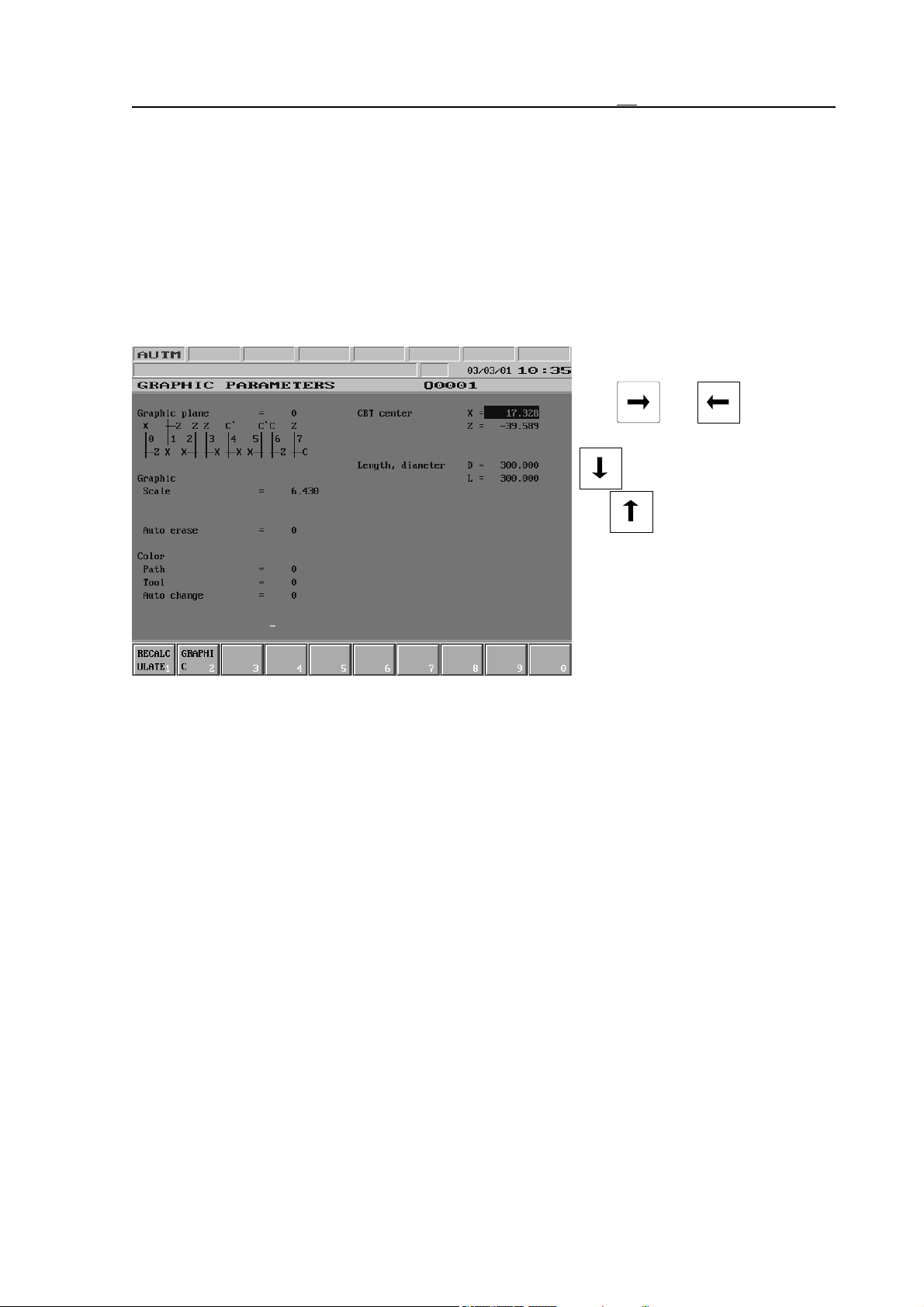
3.5.1 GRAPHIC PARAMETERS Screen
In the general displaying area the parameters of graphic position display can be seen in two
columns. The highlighting bar can
be moved between columns with
keys and , while
downwards by means of key
and upwards by means of
key .
The number entered for graphic
plane sets the coordinate system
(axis arrangement) of the graphic
position display. One of 8
arrangements can be chosen.
Diagrams seen on SETTINGS
screen show the direction of axes in each case; The axis name is drawn to the positive direction
and the axis line positions correspond to their start positions on the screen.
With the help of work size the size of the rectangular solid, which contains the work must be
given. The specified sizes are diametric and length values, i.e., they are positive in all cases
(The work position can be influenced when selecting the graphic plane). Should the given
sizes be correct (the work sizes are positive values), then the screen center and the graphic
scale are calculated automatically.
The screen center is calculated from the work sizes and axis arrangement automatically,
However definition of the screen center does not change sizes. The point defined as screen
center will always be in the center of the screen at the start of graphic position display.
The graphic scale defines the size of drawing displayed on the screen. If the scale is 1, then 1
raster equals to 1 mm. The graphic scale is always calculated from the work size and graphic
plane, when those are changed. In case of automatic scale defining the work size is taken into
account enlarged by 10%, due to which a little margin appears round the drawing displayed on
the screen. The drawing area can always be halved or doubled by means of page buttons up
and down. Naturally in this case the diagram is re-drawn. In case of graphic position display
the graphic scale occurs on the right side of the screen in form of a scale. A scale unit is 60
rasters long, thus in case the graphic scale is 1, number 60 000 displayed above indicates that
the length of a scale unit is 60 mm.
41
Page 42
3.5 GRAPHIC POSITION Screens
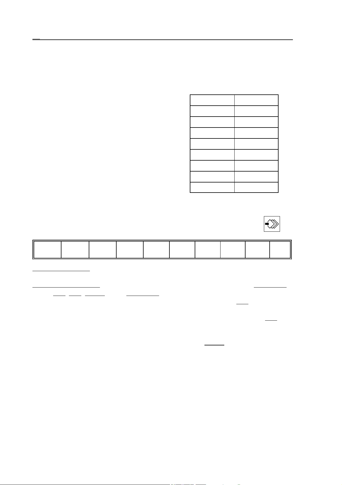
In case the value of the auto erase is other than zero, when starting the automatic program
execution both the drawing area and the buffer are cleared.
If the value of the path color is 0 rapid traverse is drawn with red, feed with green, while
thread cutting with yellow color. If the value is not zero, the rapid traverse movements are not
drawn.
In case the value of tool color is other than 0 the
movements are drawn with the appropriate tool
color (current T in the course of movement ). The
color code is the lower three bytes of the addition
of the tool number and the tool color.
If the value of auto change color is not 0 the drawing starts with the color code specified here, and
afterwards every tool change (T change) adds to
the color code.
Color Code
grey 0
blue 1
green 2
gentian 3
red 4
purple 5
yellow 6
white 7
Actions of GRAPHIC PARAMETERS Screen
The following action can be activated to the screen by pressing action menu button :
Recalc1Graphic
234567890
Recalculate Action: When pressing the softkey the position of screen center and the graphic
scale are recalculated from the work size according to the selected plane.
Graphic Action Menu:
G40
, G53, Dotted. Using Auto Erase the item with the same title in graphic parame-
After pushing the softkey the following actions appear: Auto Erase,
ters table can be set or reset. Its effect detailed above. The softkey G40 can only be
used in case of running in TEST mode. In its switched-on state the drawing appears on
the screen without tool radius compensation. In the pushed in state of button G53
drawing is done in machine coordinate system instead of the actual work coordinate
system, that is if more coordinate systems are used in the same program the tool path
can be seen separetely. In the pushed in state of button Dotted the separate points are
not connected together with lines. It is useful when the program consists of small
minute lines.
42
Page 43
3.5 GRAPHIC POSITION Screens
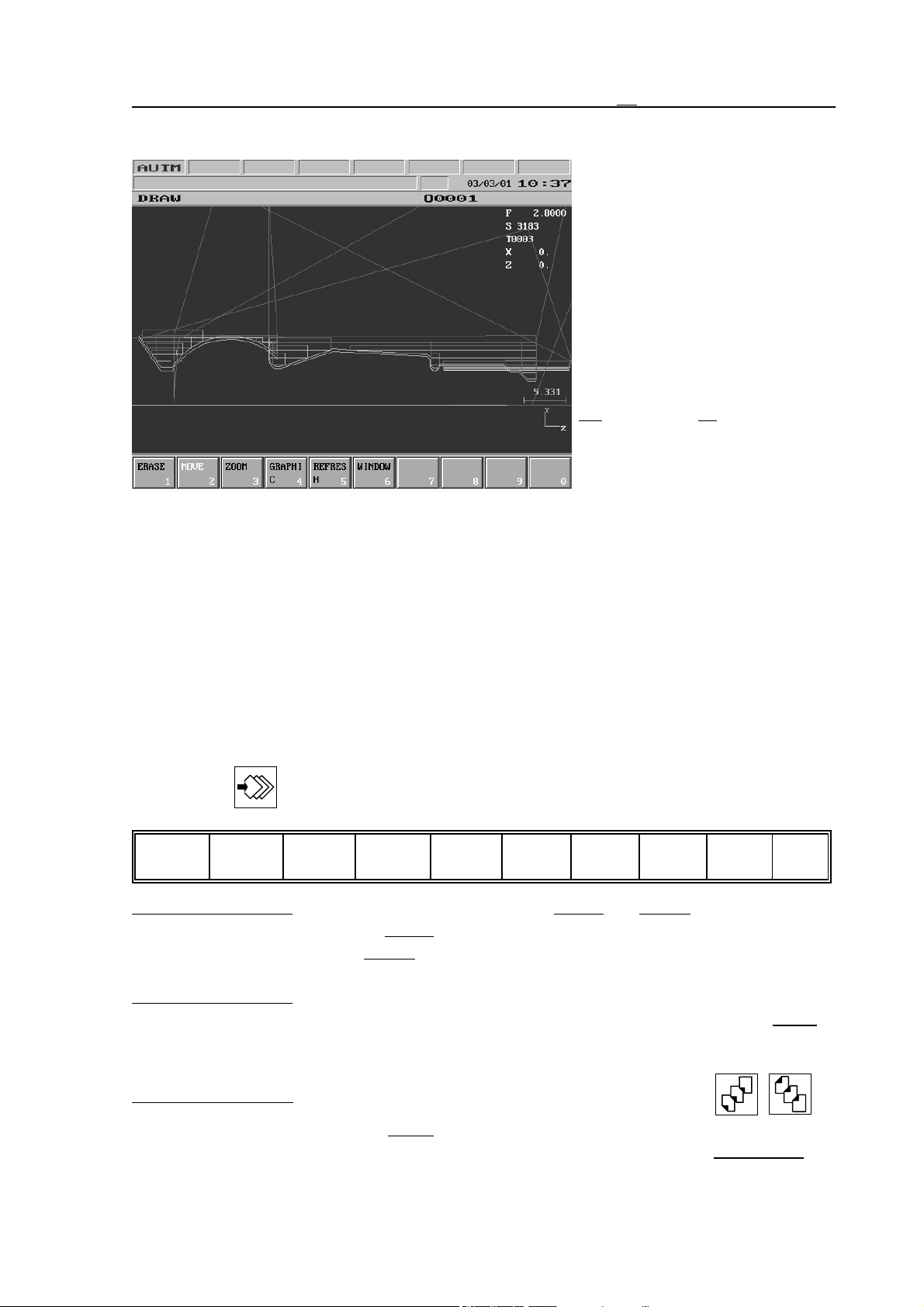
3.5.2 DRAW Screen
In the drawing area in the middle
of screen the current tool center is
shown by a cross. The following
information can be read in the top
right corner of the screen: Current
feed, spindle revolution and the
number of the current tool. Fur-
ther on in the column the position
display of axes can be seen as se-
lected on the POSITION DIS-
PLAYS screen. (see the chapter
on the page 22). In the bottom
3.1
right corner the scale, below it the
diagram symbolizing the position
of the coordinate system are
shown.
In case of automatic execution the cross indicates the current tool position. A dot is also put to
the center of the cross. The drawing depends on the speed of movement; as the points are
drawn only a few times per second, in case of fast movement the drawn tool path will be not a
continuous line, but a dotted one.
L Note: the size of the cross is defined by parameter 0561 CROSS DOT. The value entered
at the parameter specifies the length of the leg of the cross in raster. The value cannot
be greater than 7.
Actions of DRAW Screen
The following actions and action menus can be activated to the draw screen by pressing action
menu button :
Erase
Erase Action Menu:
Move
1
Zoom3Graphic4Refresh5Window
2
67890
When pressing the softkey actions Image and Buffer appear in the
menu bar. As the effect of Image action the tool path that has been drawn till now is
erased from the screen. Buffer action erases the drawing not only from the screen but
also eliminates the movement data stored in the buffer.
Move Action Menu: The softkey is always highlighted. If the drawing is to be moved in the
plane of the screen use the appropriate cursor keys. When pressing the softkey Move
four arrows appear on softkeys for each movement direction. The arrows indicate the
directions in which the drawing can be moved the same way as with the cursor buttons.
Zoom Action Menu: The drawing always can be zoomed by the paging keys: , .
When pressing the softkey Zoom actions appear for zooming up and down. The
actions refer to the page keys in the bottom left corner of the softkeys: Up (PgUp),
43
Page 44

3.5 GRAPHIC POSITION Screens
Down (PgDn). By means of softkeys, as well as the page keys the drawing area can be
halved or doubled. As the effect of Full Sceen action the centre of the screen
automatically adjusted to the middle of the tool path and scaling is set that the tool path
covers the whole screen.
Graphic Action Menu: After pushing the softkey the following actions appear: Auto Erase,
G40, G53, Dotted. Using Auto Erase the item with the same title in graphic parame-
ters table can be set or reset. Its effect detailed above. The softkey G40 can only be
used in case of running in TEST mode. In its switched-on state the drawing appears on
the screen without tool radius compensation. In the pushed in state of button G53
drawing is done in machine coordinate system instead of the actual work coordinate
system, that is if more coordinate systems are used in the same program the tool path
can be seen separetely. In the pushed in state of button Dotted the separate points are
not connected together with lines. It is useful when the program consists of small
minute lines.
Refresh action: The operation clears the screen and draws the tool path again.
Window Action menu: After using this key a frame appears on the screen. This frame can be
shrinked onto a detail of tool path with function keys appearing on soft keys or cursor
and paging keys the way as they are used in Move and Zoom operations. After paging
out of this action group the detail assigned by the frame is drawn onto the screen.
44
Page 45
3.6 SETTING Screens
3.6 SETTING Screens
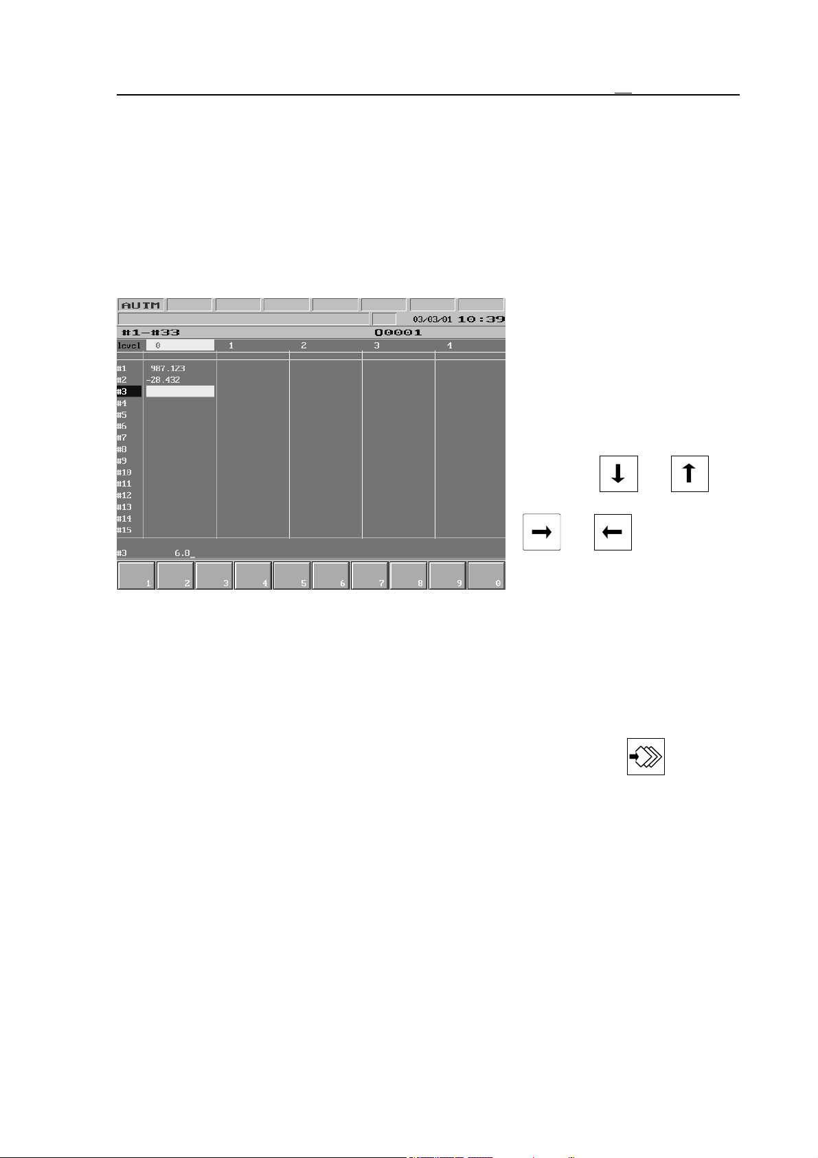
The following screens can be found in this menu; LOCAL MACRO VARIABLES #1–#33,
COMMON MACRO VARIABLES #100–#199 and #500–#599, TIMER and COUNTER,
TOOL POSITION TABLE, PLC TABLE, TOOL WEAR TABLE, USER’S PARAMETERS
and SECURITY SETTINGS. Contents of variables, timers, counters and tables are preserved
upon power-off.
3.6.1 Screen of LOCAL MACRO VARIABLES #1–#33
In the general displaying area the
local macro variables and their
values can be seen. In the five
columns the main program and
variables of the four possible
macro levels are listed. A
highlighting bar can be moved
along the variables by means of
arrow keys and ,
while with the help of arrows
and the columns
can be switched over.
Only those variables can be
edited, of which the macro level
is already open. At first only level 0 can be edited, but in case a macro call occurred during
program execution, this enables the editing of a further level. Till a macro level is not open,
editing is unnecessary, for values are given to the variables suitable for the address chain in
time of macro call, while the others are vacated.
Actions of LOCAL MACRO VARIABLES #1–#33 Screen
No action menu can be activated to this screen, by pressing action menu key a blank
action menu is displayed.
It is possible to give value directly to the macro variable by entering a number.
If a vacant value is to be specified, #0 must be entered.
Values can be specified indirectly to the macro variables. This means, that in spite of giving a
value, the variable containing the value must be entered. This way only variables #1–#33,
#100–#199 and #500–#599 can be specified. The local variables represent the values of the
current level.
45
Page 46
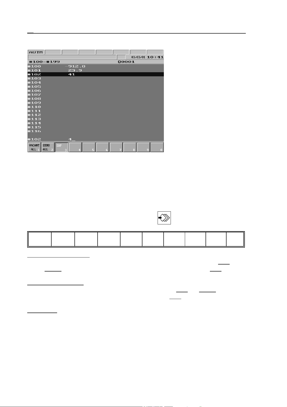
3.6 SETTING Screens
3.6.2 Screen of COMMON MACRO VARIABLES #100–#199
In the general displaying area
common macro variables
#100–#199 and their values can
be seen. Variables #120–#199
are vacated upon power-off and
when resetting automatic mode
(RESET) Variables #100–#119
are also vacated in case of value
1 of parameter CLCV, otherwise
their values are preserved.
A highlighting bar can be moved
along the macro variables by
means of arrow keys up and
down. This highlighting bar
shows the variables to be edited.
A new value can be given to the
variables in the bottom line. By terminating data input the new value is written in the variable.
Values can also be given to macro variables indirectly; By entering the code of another macro
variable (e.g.: #540) it registers the value of that variable. By entering #0 the macro variable is
vacated.
Actions of COMMON MACRO VARIABLES #100–#199 Screen
The following actions and action menus can be activated to the screen of COMMON MACRO
VARIABLES #100–#199 by pressing action menu key :
Vacant
all 1
Vacant All Action Menu:
Zero
all 2
Exp
34567890
When pressing the key the question CLEAR VACANT ALL?
can be seen in the bottom left part of general displaying area, together with Exec and
Cancel actions n the menu bar, the meaning of which is the usual. With Exec in effect
all macro variables are vacated (#0).
Zero All Action Menu: When pressing the key the question ZERO ALL? can be seen in the
bottom left part of general displaying area, together with Exec and Cancel actions in
the menu bar, the meaning of which is the usual. With Exec in effect all macro variables
are zeroed (0).
Exp Action: When pressing the key the exponent of the variable can be entered.
46
Page 47
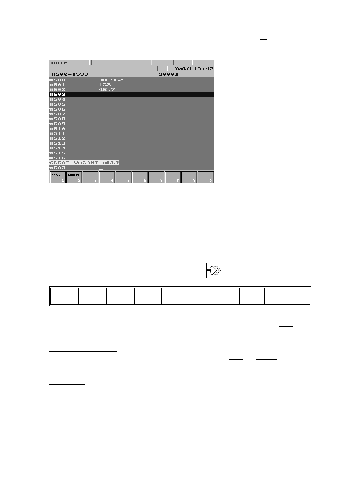
3.6 SETTING Screens
3.6.3 Screen of COMMON MACRO VARIABLES #500–#599
In the general displaying area
common macro variables
#500–#599 and their values can
be seen. These variables are not
vacated upon power-off or when
restoring automatic mode
(RESET), on the other hand by
switching to parameters, when
saving parameters they are saved
to the external device, and when
loading parameters the original
values are overwritten.
A highlighting bar can be moved
along the macro variables by
means of arrow keys up and
down. This highlighting bar
shows the variables to be edited. A new value can be given to the variable in the bottom line of
general displaying area. By terminating data input the new value is written in the variable.
Values can also be given to macro variables indirectly; By entering the code of another macro
variable (e.g.: #124) it registers the value of that variable. By entering #0 the macro variable is
vacated.
Actions of COMMON MACRO VARIABLES #500–#599 Screen
The following actions and action menus can be activated to the screen of COMMON MACRO
VARIABLES #500–#599 by pressing action menu key :
Vacant
all 1
Vacant All Action Menu:
Zero
all 2
Exp
34567890
When pressing the key the question CLEAR VACANT ALL?
can be seen in the bottom left part of general displaying area, together with Exec and
Cancel actions in the menu bars, the meaning of which is the usual. With Exec in effect
all macro variables are vacated (#0).
Zero All Action Menu: When pressing the key the question ZERO ALL? can be seen in the
bottom left part of general displaying area, together with Exec and Cancel actions n
the menu bar, the meaning of which is the usual. With Exec in effect all macro variables
are zeroed (0).
Exp Action: When pressing the key the exponent of the variable can be entered.
47
Page 48
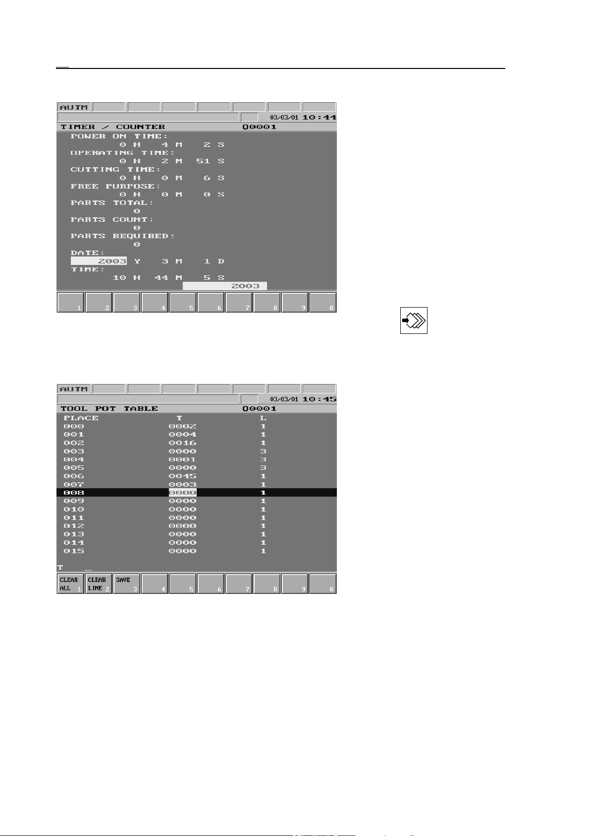
3.6 SETTING Screens
3.6.4 TIMER AND COUNTER Screen
In the general displaying area the
different timers and counters can
be seen. The highlighting bar can
be moved to the timer or counter
to be modified by means of
arrow keys. Apart from the
operating time the values are
free to overwrite.
Actions of TIMER AND
COUNTER Screen
No action can be activated to
this screen, a blank action menu
is displayed by pressing action
menu key , however the
values of timers and counters can be overwritten only in this state.
3.6.5 TOOL POT TABLE Screen
In the general displaying area the
tool pot table can be seen. The
values of the table are preserved
upon power-off.
In case not a local coded tool
handle, but a random access
magazine handle is to be used, a
tool pot table is needed, in which
the pot number of the magazine
and number of the tool found in
it can be selected.
Note
Local coded tool handle means,
that reference to the tool is
made at address T by the pot
number of the magazine, in
which the desired tool can be found.
If tool reference is not local coded, a table is needed, which shows, which tool number can be
found in which pot of the magazine.
Random access magazine handle means, that the position of tools in the magazine is not
fixed. The returning tool (taken from the spindle) is not taken back into the position it was
taken out, but into the nearest vacant position in magazine, in the simplest case in place of
the selected (new) tool.
48
Page 49

3.6 SETTING Screens
The length of the tool pot table can be set in parameter MAGAZINE No. 0061. In parameter
MAGAZINE the number of tool pots in the magazine is to be entered. Line 0 of table shows
the code of the tool in spindle, i.e., the spindle is pot No. 0.
In the first column of the table the number of tool position or pot, in the second column the
under address T the number of the tool in pot, while in the third one under address L the width
code of the tool can be found.
Usage of width code
In case of fix access magazine handle, i.e., the tool taken out is taken back into from where it
was taken, the tool width, i.e., how many pots are being occupied is of no interest.
In case of a random access magazine handle position may also have to be ensured for tools,
that are more-than-one tool pot wide. Therefore tool positions, in which extra wide tools can
be placed, should have to be selected. This is why a width code must be given to each tool in
the tool pot table.
This is needed, for in case of a random access magazine handle the returning tool can be taken
to the place of the selected one, should the two tools have the same width code. If however the
width of the two tools differ, the returning tool cannot be taken back in place of the selected
one. In this case the - to the replacement - nearest vacant position, of which the width equals
to that of the returning tool must be searched for.
The following width codes can be entered to the table (under address L):
1 (normal size),
3, 5 or 7.
The tool that has a width of 3 occupies both to the left and to the right 1-1, that of the width of
5 occupies 2-2, while that of the width of 7 reserves 3-3 positions in the magazine. This way
special pots can be selected in the magazine, into which the extra wide tools are placed.
In case of extra wide tools to the pot number, into which the tool is taken also the tool number
and the tool width code must be entered. As for the 1, 2 or 3 pot numbers before and after it,
to the tool number 0, while to the width the appropriate width code is to be entered. If a tool is
taken from the magazine to the spindle in line 0 the tool number and the tool width also has to
be entered, and the tool number is to be deleted in the line, from which the tool was taken.
However the width code must be preserved in the table, for to show the returning tool, that the
pots are reserved for extra wide tools.
For more information on handling the tool pot table turn to the machine tool builder.
Actions of TOOL POT TABLE Screen
The following actions are activated by pressing action menu key :
Clear
all 1
Clear
line 2
Save
34567890
Clear All Action Menu: When pressing the key the question CLEAR ALL? can be seen in
the bottom left part of general displaying area, together with Exec
in the menu bar, the meaning of which is the usual. With Exec
and Cancel actions
in effect the entire table
is cleared.
Clear Line Action Menu: When pressing the key the question CLEAR THIS LINE? can be
seen in the bottom left part of general displaying area, together with Exec and Cancel
49
Page 50
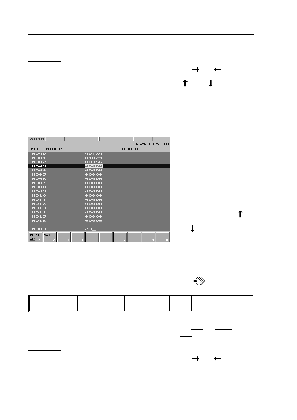
3.6 SETTING Screens
actions in the menu bar, the meaning of which is the usual. With Exec in effect the
selected line is cleared.
Save Action: When pressing the key the program number can be entered into the bottom data
input line. In case the input is terminated by any of the keys or , the
program can also be named there. As the effect of keys and values are
saved in the appropriate macro variable. It is registered in the directory not under
program number O, but under address T. Restoring values of the table is discussed in
the chapter 3.3.1 on the page 30 “DIRECTORY Screen” Run act ion menu Table
action.
3.6.6 PLC TABLE Screen
In the general displaying area the
PLC table can be seen. Its length
is specified in parameter 0062
PLC_TAB. The table can be
optionally used by the machine
tool builder.
The contents of the table are
preserved upon power-off.
The highlighting bar can be
moved along the items of table
by means of arrow keys
and .
The items of the table can be
overwritten.
For information on usage of the table turn to the machine tool builder.
Actions of PLC TABLE Screen
The following actions can be activated by pressing action menu key :
Clear
all 1
Save
234567890
Clear All Action Menu: When pressing the key the question CLEAR ALL? can be seen in
the bottom left part of general displaying area, together with Exec and Cancel actions
n the menu bar, the meaning of which is the usual. With Exec in effect the entire table
is cleared..
Save Action: When pressing the key the program number can be entered into the bottom data
input line. In case the input is terminated by any of the keys or the
50
Page 51
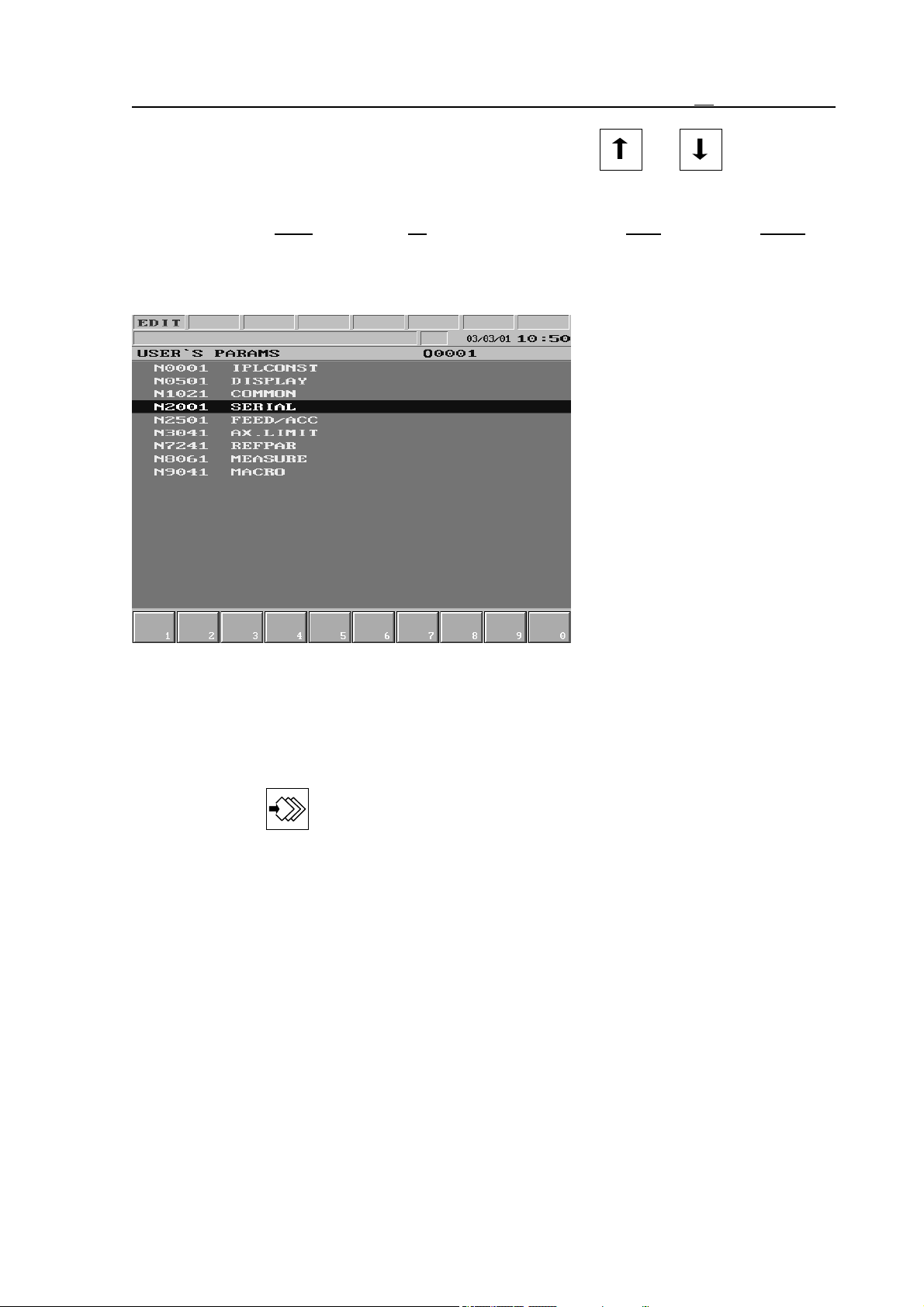
program can also be named there. As the effect of keys and values are
saved in the appropriate macro variable. It is registered in the directory not under
program number O, but under address T. Restoring values of the table is discussed in
the chapter 3.3.1 on the page 30 “DIRECTORY Screen” Run action menu Table
action.
3.6.7 USER’S PARAMETERS Screen (User’s Params)
area.
3.6 SETTING Screens
In the general displaying area a
restricted part - that can also be
set by the user - of the parameters can be seen. The highlighting bar can be moved along the
groups seen in general displaying
area by means of arrow keys up
and down. The selected group
can be opened with the help of
arrow key right, while with
arrow key left the previous level
can be displayed. If the
highlighting bar stands on a parameter, a new value can be
given to the parameter in the
bottom line of general displaying
Actions of USER’S PARAMETERS Screen
No action menu can be activated to this screen, a blank action menu is displayed by pressing
action menu key , however the values of parameters can be changed only in this state.
Editing of parameters is only permitted in EDIT mode.
51
Page 52
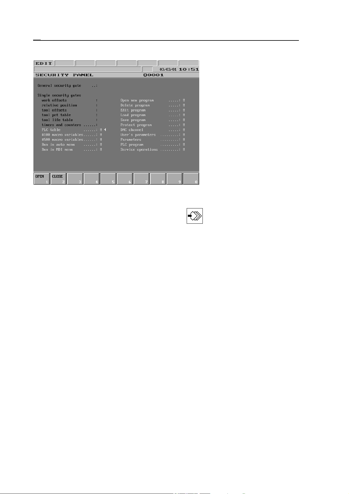
3.6 SETTING Screens
3.6.8 SECURITY PANEL Screen
The control provides wide-range
data security service. The picture
shows the SECURITY PANEL
screen. When the general
security gate is open the other
security gates have no significant
role, thus all actions listed on
the screen can be executed even
if the symbol . is displayed
beside the action.
If however the general security
gate is locked, i.e., the symbol
is seen beside the caption the ac-
tions, beside the name of which
lock symbol . is displayed,
cannot be executed. If e.g. pa-
rameters are to be edited and this action is locked display . in the 7th field of status bar warns
.
us t hat this action is closed in case action menu button is pressed on parameters screen.
The general security gate, the DNC channel, the parameters, the PLC program and the
service operations have
generated code, or
PLC key,
that means that in case of opening, either as an answer to the digits displayed by the control
another number generated from those digits must be given, or the security gate can be opened
in the open (enable) state of the key switch mounted on the machine.
The other functions have
fix code, or
PLC key,
that means that these functions are opened either with a code given in the below table or in the
open (enable) state of the key switch mounted on the machine.
52
Page 53
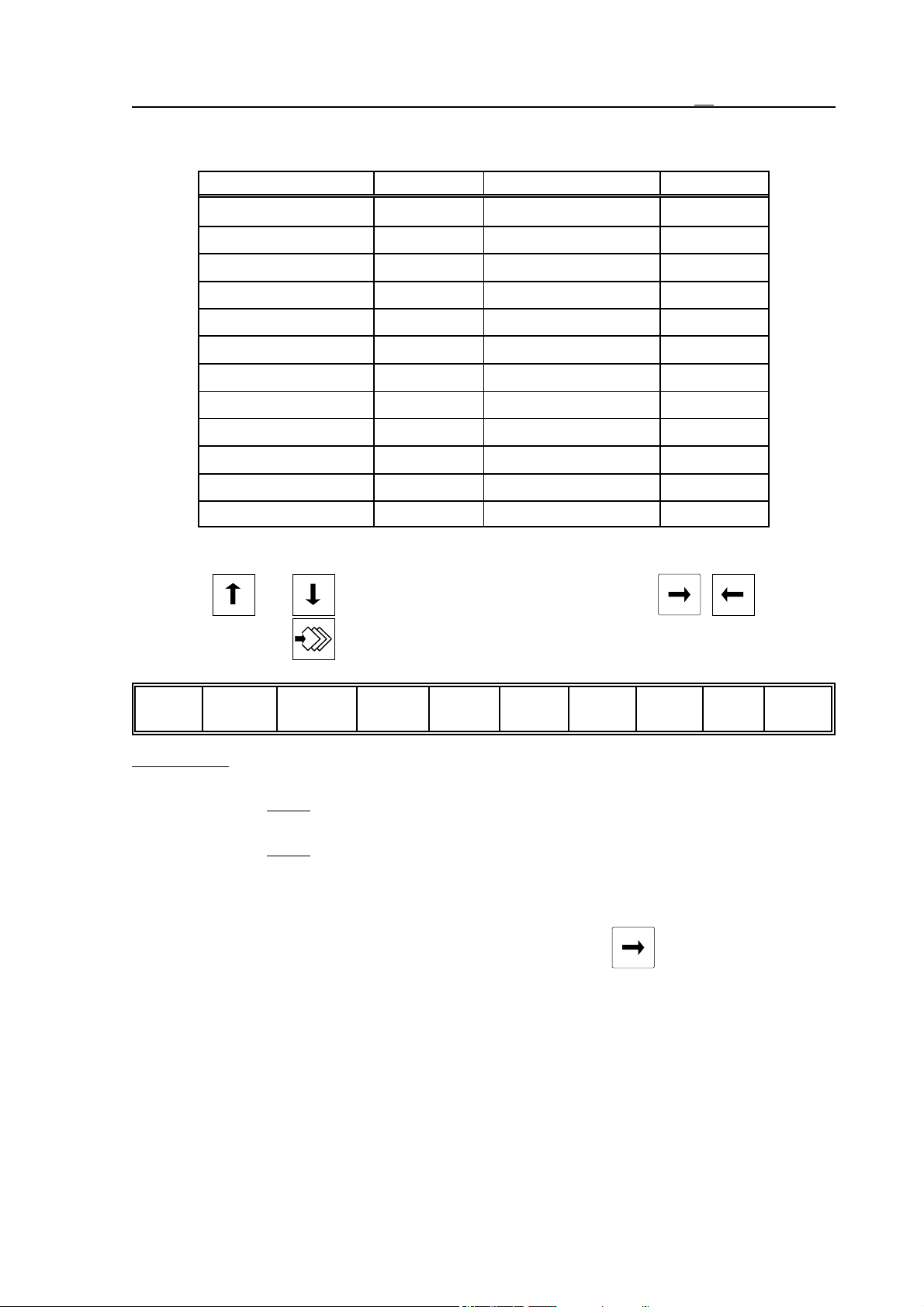
The below table contains the codes of the appropriate functions:
Function Code Function Code
3.6 SETTING Screens
General Security Gate
work offsets
relative position
tool offsets
tool pot table
tool life table
timers and counters
PLC table
#100 macro variables
#500 macro variables
run in auto menu
run in MDI menu
Generated
15962
15962
15962
15962
15962
7895123
15962
95148
95148
456852
357159
open new program
delete program
edit program
load program
save program
protect program
DNC channel
user’s parameters
parameters
PLC program
service operations
95148
95148
95148
95148
95148
7895123
Generated
7895123
Generated
Generated
Generated
Symbol = (cursor) can be moved to the desired data security service within a column by means
of buttons and . If columns are to be switched use buttons , .
If action menu button is pressed the following actions are offered:
Open1Close
234567890
Open action: If a locked function is to be opened and security key is at disposal move symbol
= (cursor) to the function. Turn the data security key to enable position on the machine
than press Open
button.
If no data security key is on the machine move symbol = to the function to be enabled
than press Open button.
In this case, provided the function to be opened has fix code, message
Code: _ _ _ _ _ _ _ _
appears in the bottom line. After entering the appropriate fix code taken from the above
table the data input can be closed with the help of button and the function is
enabled.
If the function has generated code, the following message is displayed in the bottom
line:
nnnnnnnn code: _ _ _ _ _ _ _ _
where nnn is an eight-digit number. Start Decoder program on PC and enter the digits
seen on control screen. The key code (a 5 digit number) generated by Decoder
program must be entered from numeric keyboard to control. After the appropriate code
53
Page 54

3.6 SETTING Screens
is entered the data input can be closed by means of button and the function is
enabled.
Close action: If a function is to be locked move symbol = (cursor) to the function. Press Close
button. The selected function is locked independent of the state of the general security
gate.
54
Page 55
4 Editing part programs
4 Editing Part Programs
4.1 Structure of Part Program
The part program is made up of blocks. A block consists of words.
Word: Address and Data
A word is formed by two components: Address and data (e.g., X127.064 or Z#103). The
address may comprise one or more characters (X, Z in the example), while the data may be:
SQ a number that may have integer and decimal number as well (127.064 in the example)
SQ expression (#103 in the example) that may contain arithmetic or logic operations on
variables and numbers.
Some addresses may be given a sign or operator I, independent of the data being number or
expression.
Words can be separated by means of space key for the sake of lucidity, although its use is not
obligatory.
Should a word (a string between two spaces) exceed the length of the given line while typing
the editor displays the whole word in a new line.
Block
A block consists of words. The blocks in memory are separated by character s (Line Feed).
During program editing termination of a block is performed by pressing <ENTER> key
due to which line feed occurs and at the same time character s is adjusted to the end of the
terminated block automatically. As the effect of the key the cursor goes to the beginning of
next line.
The start of a new block (character s) is indicated by character > in the first column of screen.
In case the block does not have enough room in a line the first column of the following line is
left empty and the first character is put in the second column.
Block number can be written at the beginning of blocks at address N. The application of block
numbers in blocks is not compulsory.
Block numbering can be automatized. If value of parameter 0567 N STEP is other than 0, the
block number is increased by the value given at the parameter for each push of the <ENTER>
key and this is automatically inserted to the beginning of the new block at address N. If
for example the value of parameter is 10 the block numbers are increased by ten: N10, N20,
N30, ...
Comments starting by character "(" and ending by character ")" can also be written in the
blocks.
Program number and program name
The program number and program name are used to identify the program. Usage of program
number is mandatory, that of a program name is not. The program number is the exclusive
identifier of the program in the directory, while the program name plays only informatory roles.
The address of program number: O. The address must always be followed by 4 digits, i.e., the
leading zeros must also be filled in.
The program name is an arbitrary string between opening and closing brackets "(" and ")". The
program number and the program name are separated from the rest of program blocks in
memory by character s.
55
Page 56

4 Editing part programs
Beginning and end of program
The program begins and ends with character %.
As a new program is loaded with the help of NEW action on DIRECTORY screen string
%Onnnns%
is formed automatically.
In the course of editing a part program on the CNC the opening and closing % characters
and the program number (Onnnn) do not appear in the program list and edit field therefore
they can not be altered.
If one edits a part program on an external device e.g., on a PC the opening and closing %
characters and the program number (Onnnn) must be typed in.
Program format in memory
The program in memory is a set of ASCII characters. Its format is:
%O1234(PROGRAM’S NAME)s/1 N12345 G1 X0 Y...sG2 Z5....s.....s.....sG0
G40...M 2%
In the above string:
s represents Line Feed character,
% stands for the beginning and end of program.
Program format in case of communicating with an external device.
The above program format is applicable also in case of communicating with an external device.
56
Page 57
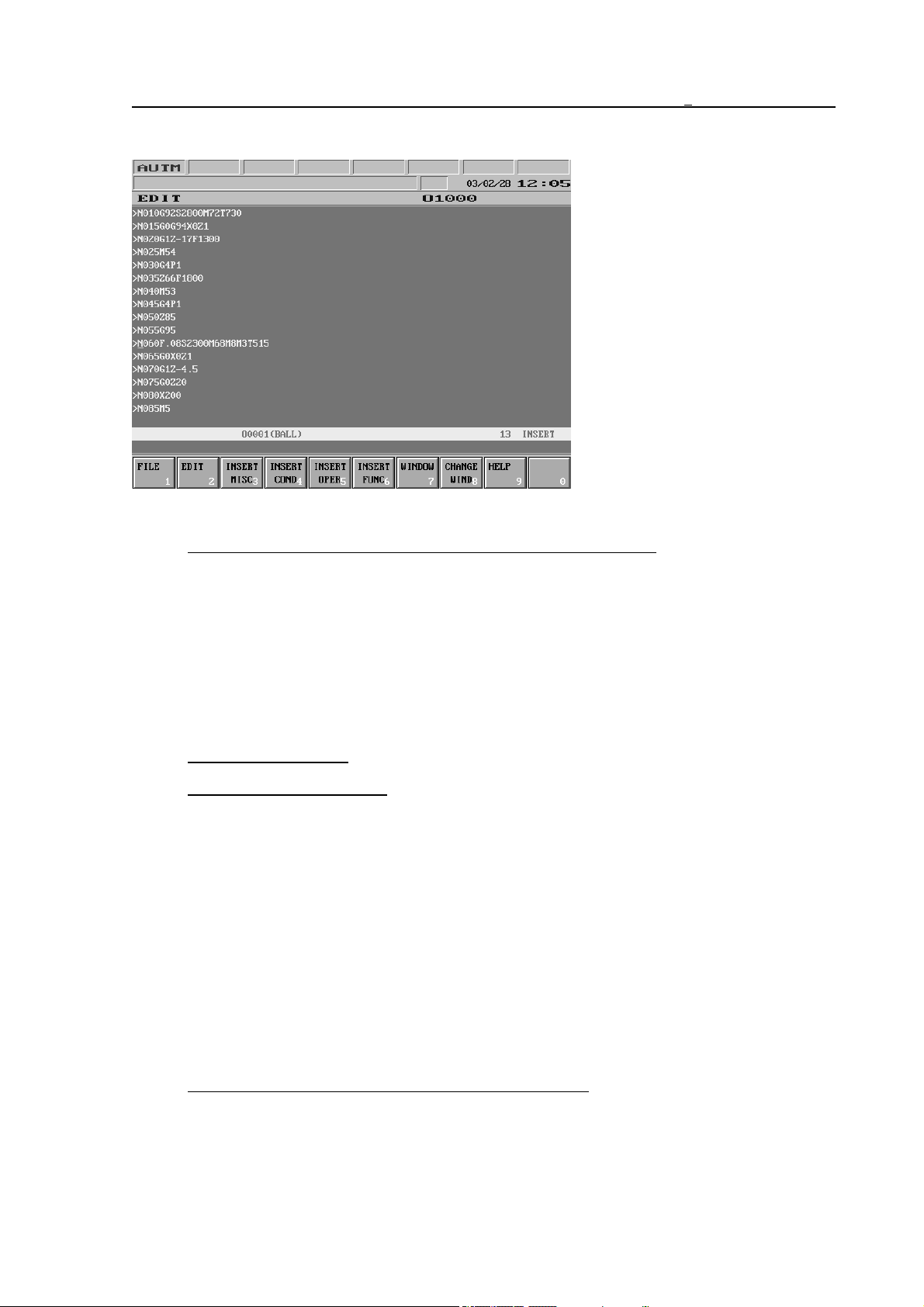
4 Editing part programs
4.2 Division of EDIT Screen during Editing
19 lines are kept for editing in
the middle of screen. The
division of these is as follows:
Lines ranging from No. 1 to No. 16: program list and edit field.
In the first column only character > representing a new block, i.e., code s may appear. The
first character of the block occurs in the second column. Otherwise if a new line must be
opened on screen for the block does not have enough room in one line, the first column
remains empty.
The text runs from the 2nd column to the 80th column and in case there are more than 79
characters in one line the text goes on in the next line.
If the last character of the word is over the 79th column the whole word occurs in the
following line starting from the 2nd column.
Line No. 17 is empty.
Line No. 18 is a status bar.
Texts written here are highlighted.
The structure of the line is as follows:
* message * window1 * window2 * line number * operation mode *
message: error messages are displayed here.
Window1: the number of program (Onnnn) edited is shown here as well as its name of which is
displayed as much as possible. In case two windows are applied the number and name of the
opened program in the upper window are displayed.
Window2: the number of program (Onnnn) being in the second, lower window is shown here
as well as its name.
Line number: number of logic lines (blocks, characters s).
Operation mode: INSERT or OVERWRITE.
The program number of the active window is highlighted.
Line No. 19.: editor error message and data input line.
This is the field for the display of error messages sent by the editor and for data input in the
course of different actions (e.g., search).
57
Page 58
4 Editing part programs
4.3 Basic Editing Functions: Typing, Cursor Moving, Delete, Insert, Select
The editing gets started as the effect of action menu key .
Basic editing functions are implemented with the help of the fo llowing keys:
– characters: <A>, <B>, ... <Z>. By their use capital letters can be typed in.
– Shift button: . In case the key is kept pressed down and another key is pushed
meanwhile, the second character indicated on the key is entered. Should letter keys be
pushed and no secondary character shown on it, small letters are typed
– digit keys: <0>, <1>, ...<9>
– space:
– decimal point:
– minus character <–> (does not switch sign during program editing):
– move cursor up, down: ,
– move cursor right, left: ,
– new line (s): (Enter)
– go backwards and delete: (Backspace)
– delete: (DEL)
– insert: (INS)
– page up: (PgUp)
– page down: (PgDn)
Typing
Characters, signs and the space can be entered uninterruptedly by pressing down the
appropriate key or keys. The place of input is where the cursor points at.
Word wrap
Should a word (a string between two spaces) exceed the length of the given line while typing
the editor displays the whole word in a new line.
New block
During program editing termination of a block is performed by pressing <ENTER> key
due to which line feed occurs and at the same time character s is adjusted to the end of the
terminated block automatically. As the effect of the key the cursor goes to the beginning of the
next line and the input of a new block can be initiated.
58
Page 59
4 Editing part programs
If value of parameter 0567 N STEP is other than 0, the block number is increased by the value
given at the parameter for each push of the <ENTER> key and this is automatically
inserted to the beginning of the new block at address N.
If for example the value of parameter is 10 the block numbers are increased by ten: N10, N20,
N30, ...
Moving the cursor
As the effect of right key the cursor goes to the next character. Should the line (last
character or space) on the screen end earlier than the right verge of screen, the cursor goes to
the first character of the following line, if there is. If the text ends there the cursor stands still.
As the effect of left key the cursor goes to the previous character. Should it be on the
left verge of the screen, the cursor goes to the finishing character of the previous line,
independent of where the previous line ends. If the text starts there the cursor stands still.
As the effect of down key the cursor goes to the following line. Should there neither be
character nor space in that column of the next line it goes to the last character of the line. If
there is no text in the succeeding line what so ever the cursor stands still.
As the effect of up key the cursor goes to the previous line. Should there neither be
character nor space in that column of the last line it goes to the last value character of the line.
If there is no text in the previous line what so ever the cursor stands still.
As the effect of the page down key the cursor goes to the following page, so that a
whole block is seen on the bottom of screen and it appears after the last character of the block.
.
As the effect of the page up key the cursor goes to the previous page so that the first
line of the screen always shows the beginning of a block (code s) and it appears on the first
character. In case no more paging can be done, it goes to the first character of the text.
Delete
When pressing key <DEL> the character on which the cursor stands is deleted, while
the characters behind step forward. If due to this, the word in the next line has now enough
room in this line, it also steps forward.
In case a space separating two words is deleted, the word drawn together is written in one.
Should the space be at the end of a line, i.e., the two words be in other lines (and the block not
finished yet, i.e., the following character not being s) the word is written in one and occurs
together with the cursor in the succeeding line.
If characters are deleted from a word at the beginning of the line and the shortened word can
already be displayed in the previous line the word together with the cursor occurs there. If
when pressing delete key the cursor stands after the last character of a logic line (block)
linefeed character s is deleted and the two blocks are drawn together.
59
Page 60
4 Editing part programs
As the effect of backspace key the character before the cursor is deleted and the
characters behind step forward. Regarding logic lines (blocks) the same rearrangements are in
force as those referring to delete key .
Insert
When opening, the editor accepts insert mode indicated by caption INSERT on the right side
of the 18th line of screen.. After pressing key <INS> the caption and the mode change to
OVERWRITE. Afterwards by pressing key repeatedly the state changes to its reverse.
In insert state the new character is written in the position preceding the cursor. Regarding the
new word formed due to the insert the same rearrangements (word wrap) are in force as those
referring to deleting.
Select
Selection is implemented by the simultaneous pressing of key <SHIFT> and cursor
moving keys , , , . The selected text is shifted
one character right by means of keys and ,
one character left by means of keys and ,
one line down by means of keys and ,
one line up by means of keys and .
Selection is deleted with the help of cursor moving keys of the contrary direction.
Deleting the selected text
The selected text is deleted by means of key del .
Value range test
The editor does not make any sort of value range or other syntactic test.
60
Page 61
4 Editing part programs
4.4 Editor Action Menu
The following actions as well as action groups are available for edit ing, when action menu key
is pressed:
File
1
Edit
Insert
2
misc 3
Insert
cond 4
Insert
operat 5
Insert
funct 6
Window7Change
wind 8
Help
90
4.5 File Actions: Save, Save as
File
Edit
1
Insert
2
misc 3
Insert
cond 4
Insert
operat 5
Insert
funct 6
Window7Change
wind 8
Help
90
The following actions are accessible by selecting File action group F1.
Save
123
Save
4
as... 5 6 7 8 9 0
Save Action: The edited program is saved while exiting from EDIT screen (by the use of key
) as well as periodically in the course of editing. This action must be applied when
for the sake of security an important part of the program is to be saved.
Save as Action: In case a program is to be saved with another number in the bottom data
input line message
FILE NAME: Onnnn_
appears when pressing the key. Program number O can be overwritten and the action
can be terminated by means of key <ENTER> . Should the program with the
entered number be an already existing one in the memory, message
FILE NAME: Onnnn_ EXISTING FILE. OVERWRITE? Y/N
is displayed. By pressing key <Y> the program is overwritten, while with key <N>
another program number may be given.
4.6 Edit Actions: Undo, Cut, Copy, Paste, Find and Replace
File
Edit
1
Insert
2
misc 3
Insert
cond 4
Insert
operat 5
Insert
funct 6
Window7Change
wind 8
Help
90
The following actions are accessible by selecting Edit action group F2.
Undo
1
Cut
2
Copy
3
Paste
Select
all 5
4
Find/
replac 6
Find
next 7
Find
previ 8
Replace
90
Undo Action: In case an action whether it is typing or deleting is executed within a block, by
the use of this key the previous state can be restored. If the result of editing can be
undone, the caption of the key is light, otherwise it is dark. The deleting can be undone
as far as character s closing the block is not deleted.
Cut Action: By pressing the key the block selected earlier on is deleted from the text and put
to the clipboard.
61
Page 62
4 Editing part programs
Copy Action: By pressing the key the text selected earlier on is put to the clipboard and the
original text remains at its position.
Paste Action: By pressing the key the content of the clipboard is inserted starting from the
position next to the cursor. In case the clipboard is empty, the caption of the key is
dark, otherwise it is light.
Select All Action: By pressing the key the entire program is selected.
Find/Replace Action: By pressing the key it remains pressed down. Captions
FIND: <empty> REPLACE: <empty>
appear in the bottom data input line. Afterwards the text to be searched for can be
typed in the field after caption FIND. In case the text typed in is to be changed to
another one the cursor goes to the field next to caption REPLACE on the right side of
the screen as the effect of key <ENTER> where the desired text can be written
in. By the repeated pressing of key <ENTER> the cursor swings between
captions FIND and REPLACE, therefore each text may be modified additionally. The
maximum length of the text to be found or replaced is 30 characters.
In case a text is selected before pressing Find/Replace key the selected text is
displayed automatically after caption FIND.
By a repeated push the Find/Replace key is unpressed and the cursor goes back to its
original position in the selected text. By the repeated pressing of Find/Replace key the
text written in earlier on is restored in the bottom data input line after captions FIND
and REPLACE.
Find Next Action: In the pressed-down state of Find/Replace key as the effect of Find Next
key search for the text given in FIND field is executed forwards from the position in
which the cursor stood before the pressing of Find/Replace key. The found string can
be seen in inverse mode in accordance with the selection. After the unpressing of
Find/Replace key the cursor glitters in the first character position of the found text and
the selection disappears. Should the string be not found the caption NOT EXISTING is
displayed in the message field. The message is cleared by the repeated press of
Find/Replace key, Find Previous key or the Cancel key as well as Find Next
key provided the text in FIND field is in the meantime changed and found.
Find Previous Action: In the pressed-down state of Find/Replace key as the effect of Find
Previous key search for the text given in FIND field is executed backwards from the
position in which the cursor stood before the pressing of Find/Replace key. The found
string can be seen in inverse mode in accordance with the selection. After the
unpressing of Find/Replace key the cursor glitters in the first character position of the
found text and the selection disappears. Should the string be not found the caption
NOT EXISTING is displayed in the message field in the 18th line. The message is
cleared by the repeated pressing of Find/Replace key, Find Next key or Cancel key
as well as Find Previous key provided the text in FIND field is in the meantime
changed and found.
Replace Action: After a successful search for the next or last string in the pressed-down state
of Find/Replace key, when the found text is inversed Replace key may be pressed. In
this case the string after the caption REPLACE is inserted in the text in place of the
62
Page 63
found string. If no text is given after the caption REPLACE, Replace action is
equivalent to the deleting of the found text. Undo action can also be applied after
Replace action.
4.7 Insert Actions
4 Editing part programs
File
1
Edit
Insert
2
misc 3
Insert
cond 4
Insert
operat 5
Insert
funct 6
Window7Change
wind 8
The following actions are accessible by selecting action groups F3, ..., F6:
Insert Miscellaneous Action Group:
Number1Date/time2WHILE3DO
END5BPRNT6DPRNT7POPEN8PCLOS9SETV
4
Insert Condition Action Group:
IF
LT
1
<2
LE
<= 3
EQ
=4
NE
!= 5
GE
>= 6
GT
GOTO8THEN
>7
Insert Operation Action Group:
ABS
1
BIN
2
BCD
3
FIX
4
FUP
5
NOT
OR
6
XOR8AND9MOD
7
Insert Function Action Group:
Help
90
N0
90
0
SIN
1
COS
2
TAN
3
EXP
ASIN5ACOS6ATAN7LN
4
SQRT
8
90
Number Action: The line number seen in the status line is multiplied by the value of parameter
0567 N STEP and the block number (Nnnnnn) resulted is inserted after the position
indicated by the cursor.
Date/Time Action: By pressing the key the date and time are inserted in the text as seen in the
top right corner of the screen.
By selecting further actions of the four action groups executing insertion, the string
corresponding to the caption of the key is inserted in the text.
4.8 Actions of Window
File
1
Edit
Insert
2
misc 3
Insert
cond 4
Insert
operat 5
Insert
funct 6
Window7Change
wind 8
Help
90
Window Action: By pressing the key it remains pressed down and the edit field of the screen
is divided horizontally into two windows. In both windows the program selected for
editing can be seen, making thereby possible the editing of two different parts of the
same program. In case another program is to be presented in a window the edit ing
must be exited and the program to be loaded must be selected on the DIRECTORY
63
Page 64
4 Editing part programs
screen. By returning to the EDIT screen the other program can be seen in the window
active when exiting. The active window as well as the program numbers shown in the
windows are indicated in the 18th status line. The cursor is seen in the active window,
and this is also the place where editing actions may be executed.
By a repeated push the Window key is unpressed, the screen is switched back to single
window form and the program, the window of which was active at the time of the
pressing of Window key, can be continued to be edited.
Change Window Action: Applied when two windows are present at a time. As its effect the
cursor goes to the other window. Henceforward the other window is active and editing
actions can be realized there.
4.9 Help
File
1
Edit
Insert
2
misc 3
Insert
cond 4
Insert
operat 5
Insert
funct 6
Window7Change
wind 8
Help
90
Help Action: The pressing of the key is only effective if the cursor is moved to the letter G of
a G code (e.g., G02) or if previously a G code interpretable by the help function is
selected in the text by means of shift and cursor moving keys, i.e., according to the
rules of selection. The key remains pressed down. By the repeated push of the key the
help is closed.
64
Page 65
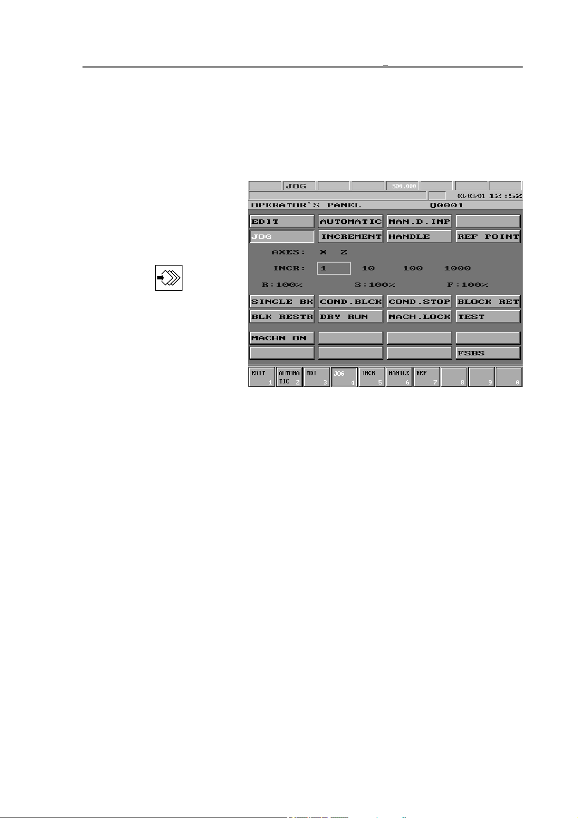
5 Switching Over Operation Modes
5 Switching Over Operation Modes
With the help of the data input keyboard the state of operation modes, switches, etc.,
displayed on the OPERATOR’S PANEL screen can be changed by means of softkeys after
action menu key has been pressed. The above switches are available not only on the OPERATOR’S PANEL screen, but also on POSITION screens. These are discussed in details in the
chapters of the appropriate screen.
When switching over an operation mode, at first one of the
below screens (functions) must
be selected: OPERATOR’S
PANEL, or POSITION.
Afterwards by pressing the ac-
tion menu key
MODES action menu needs to
be selected. In this case the captions of different operation
modes appear on the menu bar.
The desired operation mode can
be displayed by pressing the appropriate softkey.
If the machine is mounted with
NCT machine control board the operating modes can be selected directly from the
pushbuttons.
F1
LNote:
In the different computers the operation mode selection can function contrary to the abovementioned process. For example operation mode selector switches can be equipped to the
machine and the operation modes can be switched over directly by the use of these. It is
possible, that in this case operation modes cannot be selected by means of softkeys at all. For
details turn to the machine tool builder for an information material.
65
Page 66
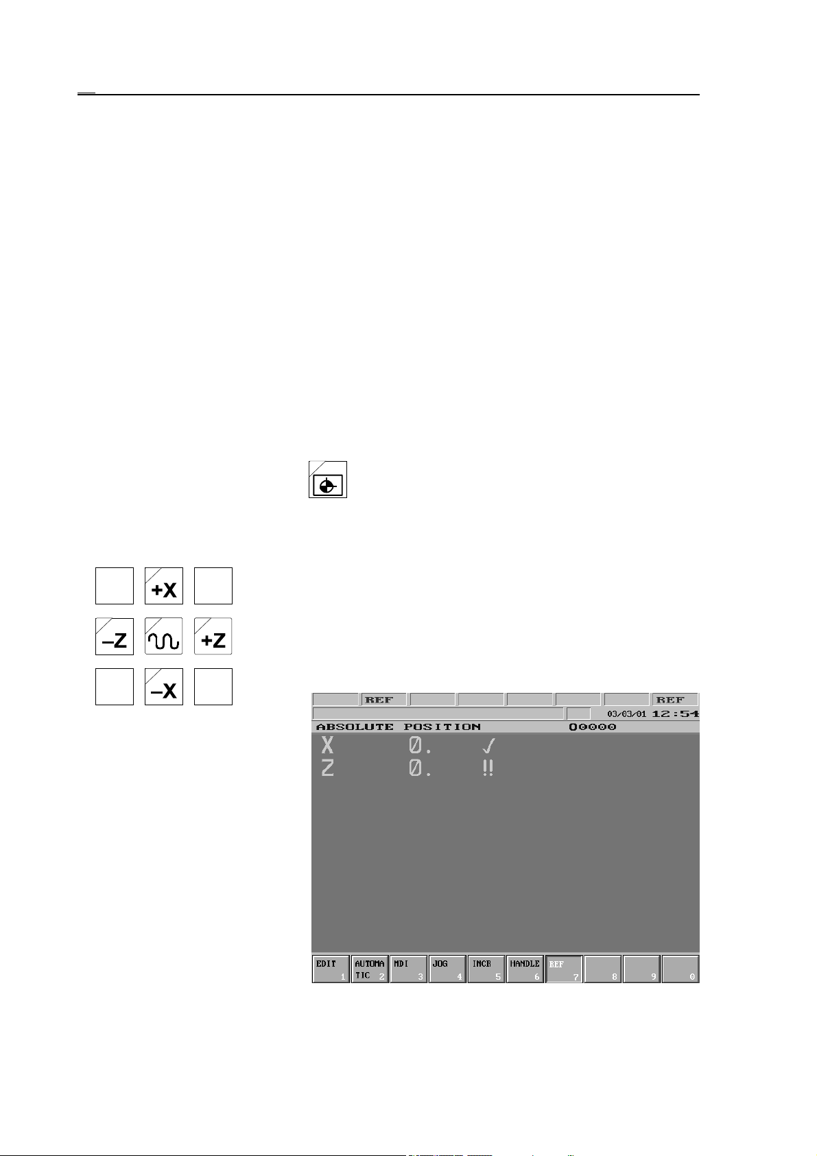
6.1 Manual Reference Point Return Mode
6 Manual Operation Modes
The manual operation modes are as follows:
Manual reference point return
Manual handle feed
Incremental jog
Jog
6.1 Manual Reference Point Return Mode
Reference point can be returned only upon power-on state of the machine, i.e. when there is no
EMG (emergency stop) state in the rightmost field (general NC state) of status bar. If one of
the axes has not been returned to the reference point, in case of that axis no absolute positioning (G90) can be programmed. The parametric overtravel also functions only after the
reference point return. The reference point return mode is indicated by caption REF in the 2
field of the status bar.
If the machine is mounted with NCT machine control board the reference point return mode
can be switched on by pressing the button.
nd
Axis Selection
After selecting the operation mode by pressing and holding down the
appropriate axis’s button returning to the reference point on the
selected axis is beginning. If the axis direction button is not held down
any longer the movement stops, if it is pressed again the process is
continued. More axes’ jog buttons can be pressed at a time, therefore
return to reference point can be made simultaneously on several axes.
On the
selected axis the direction of
movement depends on the
parameter and independent of
whether key of direction + or
key of direction ! is being
pressed. Generally on the control
panels +X, !X, +Z, !Z are
equipped. This way the movement on axes X, Z can be
directly started.
If the ABSOLUTE POSITION
screen is used during reference
point return, on the axes, on
which return to reference point
has already occurred, symbol
%is
displayed beside the position, while on the ones, on which no return to reference point
66
Page 67

6.1 Manual Reference Point Return Mode
happened yet, symbol !! can be seen beside the position. In case the reference point has been
returned on all axes REF, i.e., the caption indicating lack of reference position is cleared from
the general NC state field.
LNote:
By different machine tools return to the reference point may function contrary to the abovementioned process. It is common, that after displaying the operation mode and pressing
START button the jog buttons are to be held down for a short time, after that the process goes
on automatically. In this case the process can be stopped by pressing STOP button. For
details turn to the machine tool builder for an information material.
Types of Reference Point Return
There may be four types of reference point return. The types are determined by the machine
tool builder axis by axis in different parameters, in function of the adapted path measuring
system.
1. Reference point setting by return to switch, then standing on zero-pulse
The selected axis runs to the reference point switch at high speed, then stops. It comes off the
switch at low speed either in the direction of the running on or in the opposite one, and
searches for the first zero-pulse, and registers this position reference point.
2. Reference point return with distance coded measuring system
The selected axis searches for two neighboring zero-pulses at low speed. It detects the
absolute position of the axis by measuring the distance between the two zero-pulses.
3. Reference point return on grid
The selected axis searches for the zero-pulse at low speed and registers it as reference point.
4. Floating reference point
By pressing the appropriate jog button no movement is made, but the momentary position of
the slide is registered as reference point.
67
Page 68
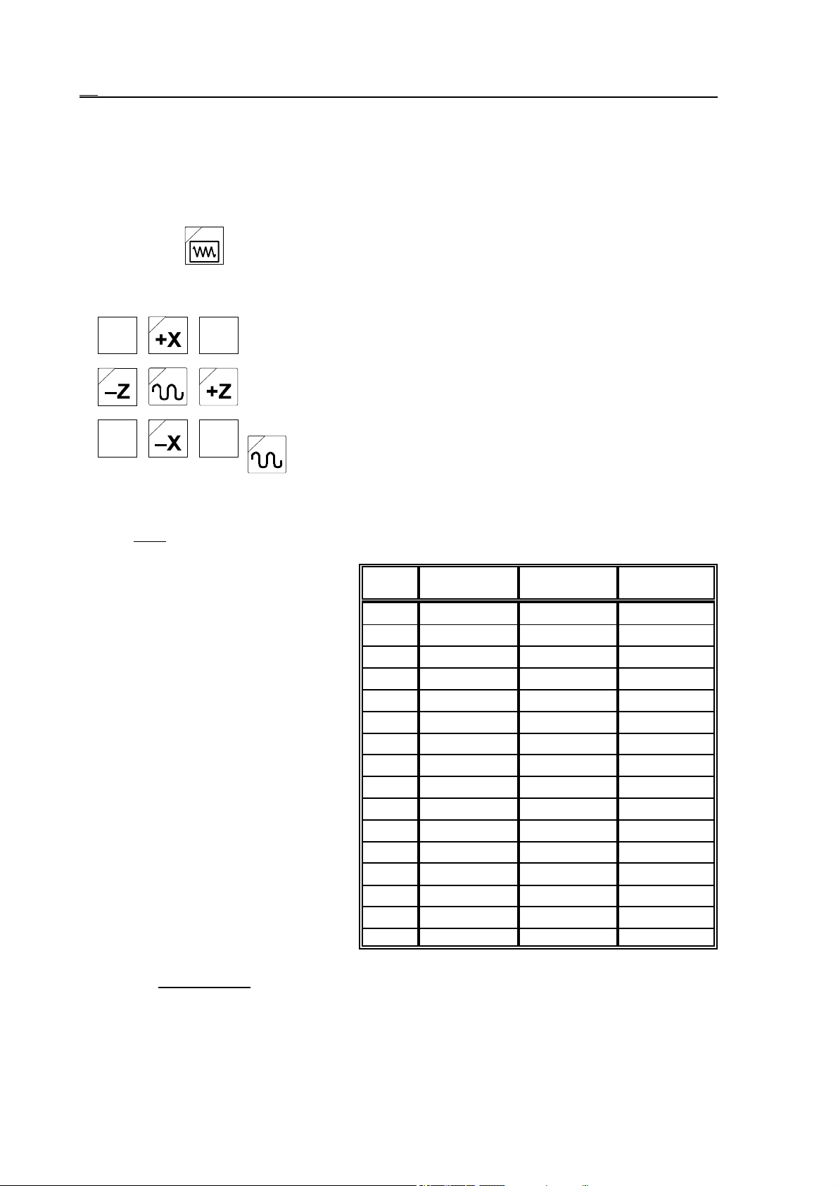
6.2 Jog Mode
6.2 Jog Mode
Jogging can only be done upon power-on state of the machine, i.e. when there is no EMG
(emergency stop) state in the rightmost field (general NC state) of status bar. After selecting
the operation mode in the 2nd field of status bar caption JOG appears.
If the machine is mounted with NCT machine control board the jog mode can be switched on
by pressing the button.
Axis Selection
The movement on axes X, Z can be directly started by pressing and
holding down the appropriate jog button.
More axes’ jog buttons can be pressed at a time, therefore more axes
can be jogged simultaneously.
In case only jog buttons are held down the appropriate axis is jogged
at feedrate. If together with the jog buttons the rapid traverse key
is pressed, the selected axes move at rapid traverse rate.
Feedrate Selection
Rate of feed jogging:
– the modal value F, if the value of parameter 1372 JOGFEED is 0.
– If the value of parameter 1372
JOGFEED is 1 the rate of
jogging is independent of
the modal value F. In this
case the rate is taken into
account on the basis of the
state of feedrate override
switch in accordance with
the table beside.
In this case the valid feedrate values can be seen in the 5
th
(interpolator) field of status bar.
%G21
mm/min
0000
1 2 0.08 0.4
2 3.2 0.12 0.64
55 0.2 1
10 7.9 0.3 1.58
20 12.6 0.5 2.52
30 20 0.8 4.0
40 32 1.2 6.4
50 50 2 10
60 79 3 15.8
70 126 5 25.2
80 200 8 40
90 320 12 64
100 500 20 100
110 790 30 158
120 1260 50 252
G20
in/min
rotating axis
°/min
The rate of rapid traverse jogging is at parameters axis by axis fixed value. Generally the rate
differs from (less than) that of G00 rapid traverse rate positioning (by the way it is also fixed at
parameters axis by axis).
68
Page 69

6.2 Jog Mode
L
Note:
The above discussed cases are the basic cases of jog mode. By different machines functions
contrary to these may be created by the machine tool builder. It is common, for example, if
pressing of a jog button is followed by the pressing of the START button, than the jog button
is not to be held down any longer. This way the movement on the selected axis is carried on
until the STOP button is pressed. For details turn to the machine tool builder for an information material.
69
Page 70
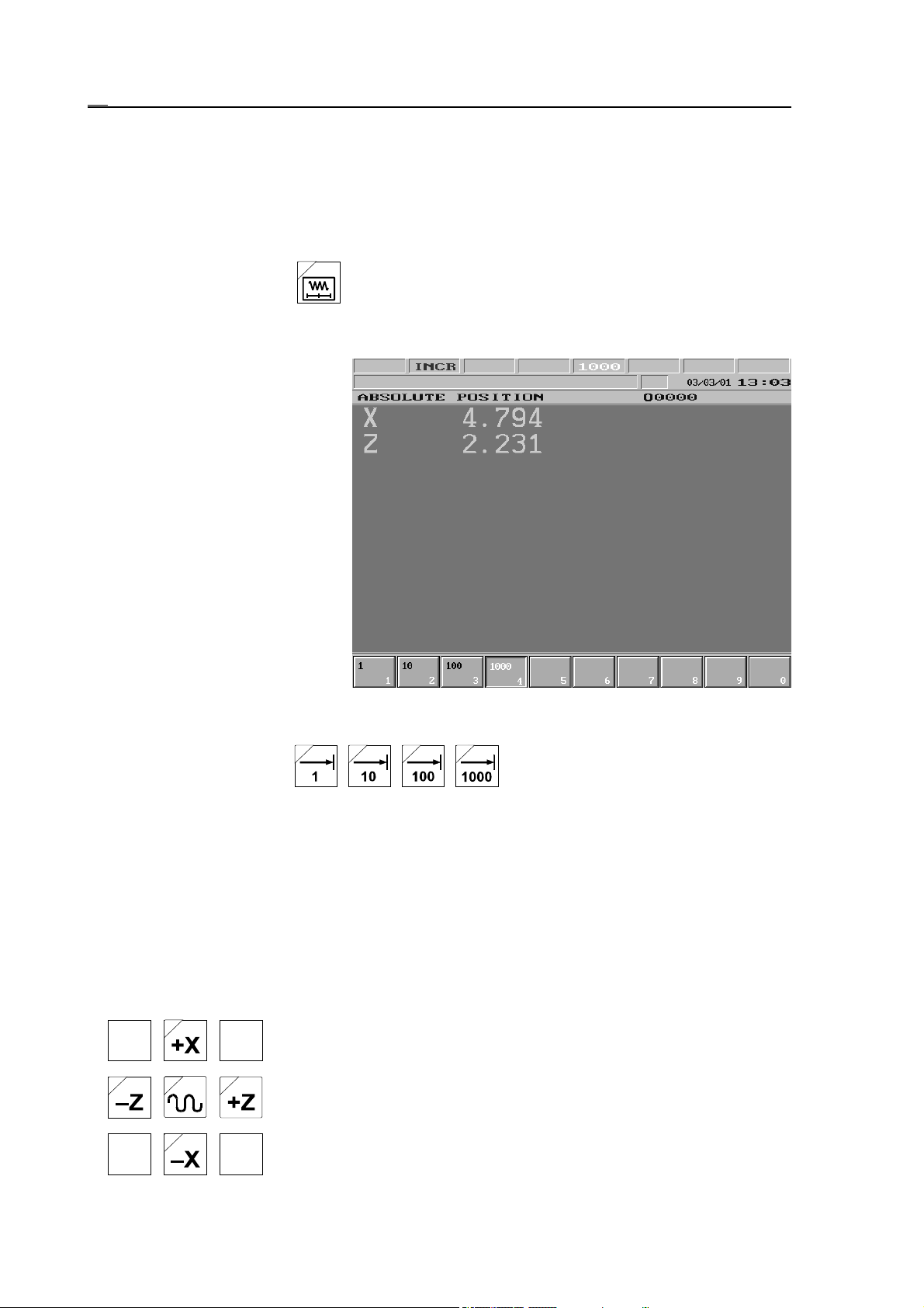
6.3 Incremental Jog Mode
6.3 Incremental Jog Mode
Incremental jogging can only be done upon power-on state of the machine, i.e. when there is
no EMG (emergency stop) state in t he rightmost field (general NC state) of status bar. After
selecting the operation mode in the 2nd field of status bar caption INCR appears.
If the machine is mounted with NCT machine control board the incremental jog mode can be
switched on by pressing the button.
Increment Selection
After selecting the operation
mode an increment size must be
selected. This can be done on the
OPERATOR’S PANEL or
POSITION screen. After
pressing the F3 action menu key
INCREMENT, the desired
increment size can be selected
with the help of softkeys. The
selected increment size can be
seen in the 5th (interpolator)
field of status bar. The increment
size means the number of
increments the selected axis
moves by pressing the axis
direction button once.
If the machine is mounted with NCT machine control board the increment size can also be
selected directly by buttons , , , .
The increment size stepped by the control (1, 10, 100, 1000 increments) is always interpreted
in the output system of the machine (metric or inch). The output increment system is determined by the measuring system adapted to the machine. If, for example, in case of a machine of
metric system (the output increment system is metric), the resolution is 0.001mm, the control
is set to G20 (inch input programming) state and 1000 increment size is selected, on the
position display of distance to go 0.0394 will be displayed as distance, which is 1 mm
increment size in inch.
If data input and position display is done in diameter on axis X, the selected incremental step
will be done in diameter too.
Axis Selection
After setting the increment size by pressing axis jog buttons the step
is started on the selected axis and in the selected direction.
70
Page 71

6.3 Incremental Jog Mode
L
Warning!
If in case of greater increment sizes the jog button is left hold for a short time, the movement
stops and the desired distance is not stepped by the control, this way preventing it from
possible collisions!
71
Page 72
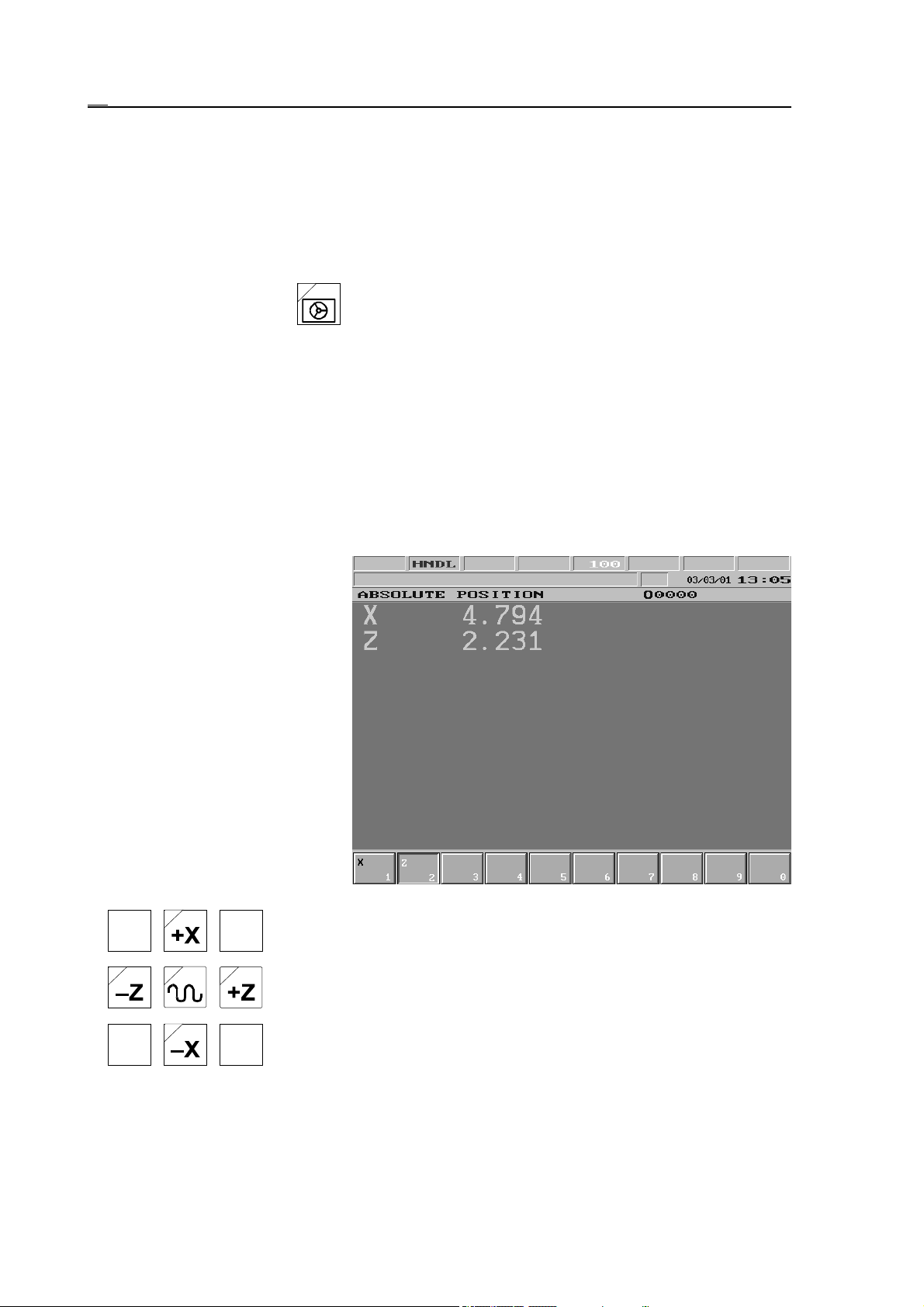
6.4 Manual Handle Mode
6.4 Manual Handle Mode
Moving by the use of manual handle can only be done upon power-on state of the machine, i.e.
when there is no EMG (emergency stop) state in the rightmost field (general NC stat e) of
status bar. After selecting the operation mode in the 2nd field of status bar caption HNDL
appears.
If the machine is mounted with NCT machine control board the manual handle mode can be
switched on by pressing the button.
Increment Selection
After selecting the operation mode an increment size must be selected. The selection and
interpretation of increment size correspond to the ones discussed in the case of incremental jog
mode. The increment size in manual handle mode shows the number of increments the slide
moves by rotating the manual handle one unit of division.
Axis Selection
The axis to be moved by the
manual handle can be selected
on the OPERATOR’S PANEL
or POSITION CHECK screen.
After pressing the action menu
key F2 AXES than the axis to be
moved can be selected by means
of softkeys.
If the machine is mounted with NCT machine control board the axis
can also be selected by the jog buttons X, Z. In this case after selecting the appropriate axis the lamps of both directions (e.g., +X and
–X) are alight.
72
Page 73

6.4 Manual Handle Mode
Speed
In case of moving by the use of the manual handle the speed of the axis depends upon the
selected increment size and upon the speed of the rotation of the handle. The movement is
started by acceleration and finished by deceleration. The pulse number rotated is always
executed, if parameter 1373 HNDLFEED is 0 therefore, if the selected axis cannot follow the
pulses coming from the manual handle those are buffered and are moved after the rotation has
been stopped. Adjust parameter 1373 HNDLFEED=1 to avoid such undesired pulse buffering.
In this case the division on the handle may differ from the movement actually done.
L
Note:
The above discussed case is the basic case of manual handle mode. By different machines
functions contrary to these may be created by the machine tool builder. If, for example, an
external manual handle is equipped, the increment and direction selection may be done with
the help of a dial. For details turn to the machine tool builder for an information material.
73
Page 74

7 Actions Executed in Manual Operation Modes
7 Actions Executed in Manual Operation Modes
7.1 Single Block Operation
A single block can be entered by selecting BLOCK INPUT screen of the PROGRAM screen
menu and pressing the action menu key. This action can be used only in jog, incremental jog
and manual handle modes. The data input is discussed in the chapter 3.3.4 “SINGLE
BLOCK Screen” on the page 34.
Only a program block not referring to previous or following blocks can be entered, i.e., for
example a block containing tool nose radius compensation cannot be entered. There are no
further restrictions, e.g. canned cycles, subprograms or macros can be started by means of
single block operation.
After terminating single block input caption SBEX appears in the 2nd field of status bar. With
the START button in effect the single block is executed.
7.2 Work Zero Point Offset and Tool Length Offset Measurement
In the course of measuring work offsets and tool length offsets by touching the workpiece
surface, of which the sizes are known, manual moving of axes is needed. It follows, that it is
practical to use manual operation modes in case of both activities. If, when measuring, switchover of spindle revolution or a new tool is needed, it can be executed by means of single block
input wit hout changing operation modes.
L
Warning!
Work offset and tool length offset measurement can be executed only after reference
point return.
74
Page 75
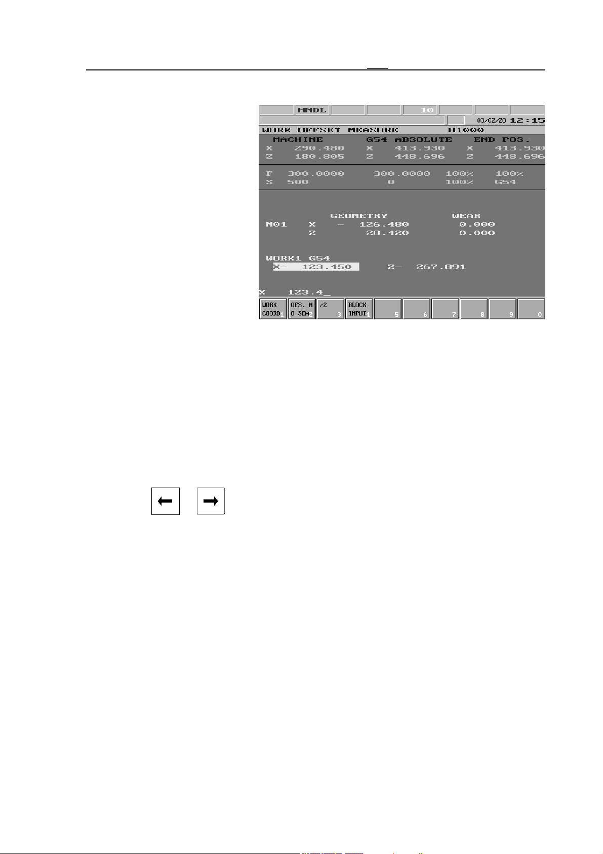
7.2.1 Work Zero Point Offset Measurement
7.2.1 Work Zero Point Offset Measurement
If work offset is to be measured
inside the machine, select
F3
W.
OFFS MEASURE (work offset
measurement) screen of OFFSETS screen menu and press
the action menu key.
The coordinate system to be
measured can be selected after
pressing softkey F1 WORK
COORDNT. (Work coordinate
system), than the appropriate
softkey F1 G54, F2 G55, ... The
selected coordinate system is not
changed to (as after the execution of the appropriate command G54, G55, ...), but is only
taken into account in the course of measuring.
Basically there may be two kinds of tool length offsets. One possibility is that the t ool length
offset equals to the X- and Z-direction tool overhang. Another one is that the tool length is
actually a coordinate offset in the direction of tool length. The control enables the operator to
take the size of a tool which is known, into account when measuring the offsets.
The length offset storage to which the coordinate system is to be measured, can be selected.
In order to do this the action key F3 OFS NO SEARCH (offset number search) must be
pressed. The offset register number, which is to be used in the course of measuring, shall be
entered under address N in the bottom data input line, than the data input must be terminated
by either key or .
75
Page 76
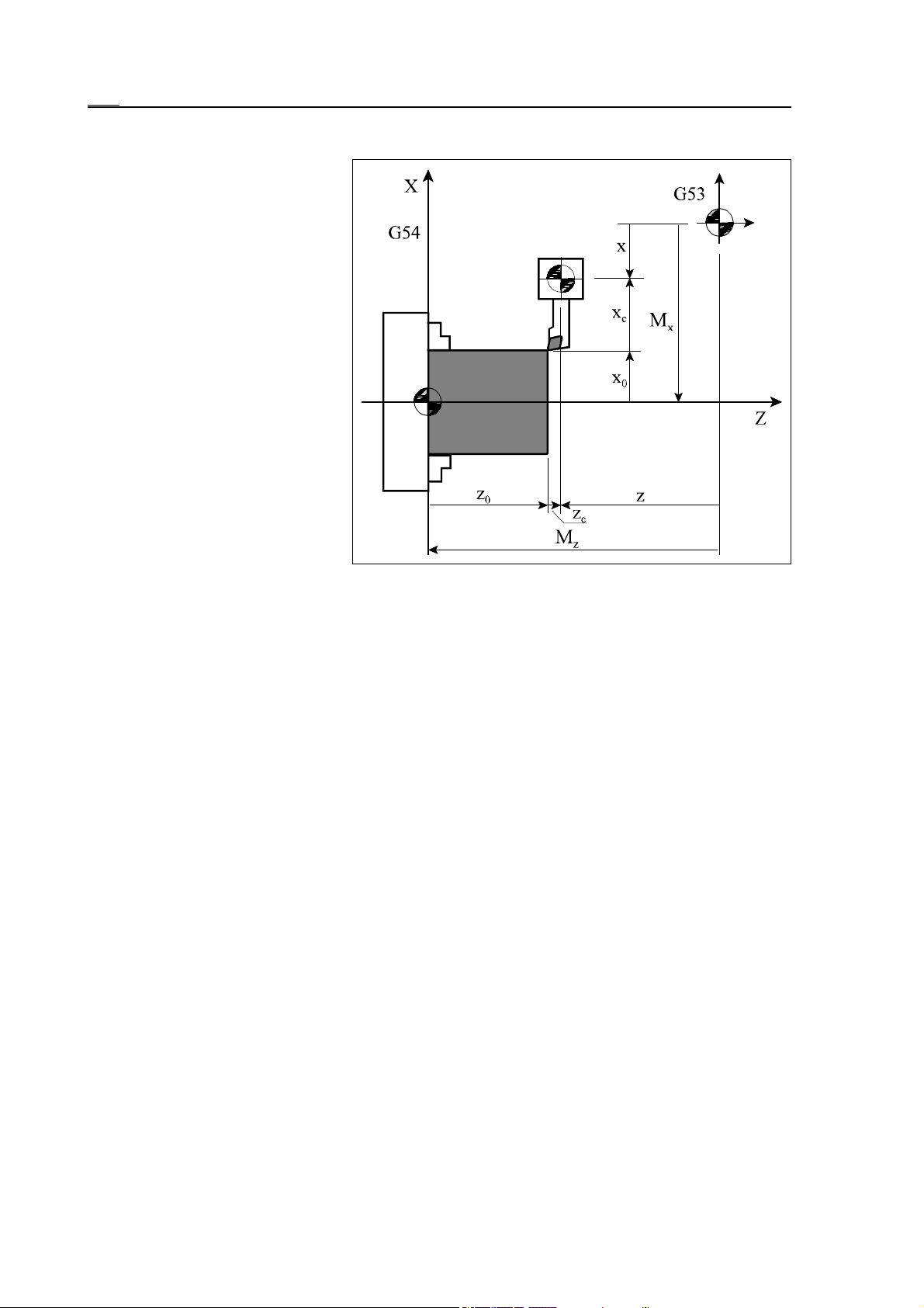
7.2.1 Work Zero Point Offset Measurement
Work Zero Point Offset Measurement, if Tool Length Equals to Tool Overhang
If tool length equals to the Xand Z-direction tool overhang
(because for example tool offset
measuring was executed on an
external measuring device) the
work offset (work zero point)
must always be measured. This
can be done by taking a cut with
a tool previously measured, in
X- and Z-direction on the
workpiece in the spindle, than
measuring the diameter and
length of workpiece on the place
where the cut was taken and entering the sizes to control. The
control takes the tool overhang
into account automatically when
calculating the work zero point
offsets, if prior thereto the tool
offset group containing its size
was selected.
The offset value can be calculated from the following equation:
Mx = x – xc – x
Mz = z – zc – z
0
0
where
– Mx, Mz: value of work zero point offset
– x, z: reference position of tool holder in machine coordinate system (excluding length offset)
– xc, zc: X- and Z-direction tool length offset
– x0, z0: data entered to coordinate Z in the course of measuring, the measured size of the
workpiece.
L
76
Note:
Values x and z of the above equation differ to position seen on position display G53, if
tool length has been called (Tnnmm). In values "x, z" the called length offset is never
taken into account. Therefore before measuring it is useful to delete tool length by
means of command Tnn00, however this only makes position display more understandable.
Page 77
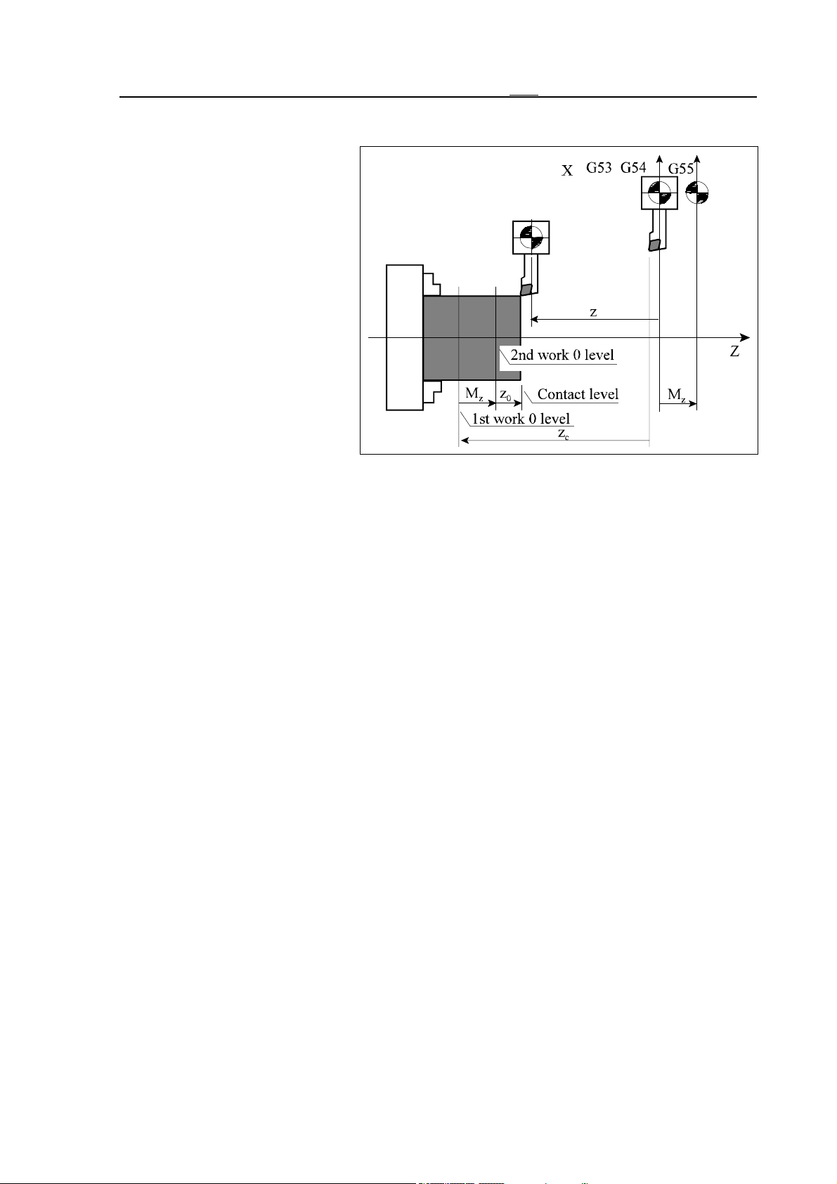
7.2.1 Work Zero Point Offset Measurement
Work Zero Point Offset Measurement, if Tool Length Equals to Coordinate Shift
If tool lengths are measured so
that they also contain the offsets
of the work zero point (see tool
length measurement) work offsets do not have to be measured.
An exception to this if the offset
needs to be compensated, as well
as if another work coordinate
system is to be used. This is
needed, for the tool length is
calculated in relation to a given
work coordinate system.
The process corresponds to the
above discussed one. The control
calculates the offset amount with
the help of the above-mentioned
equation:
Mx = x – xc – x
Mz = z – zc – z
0
0
However this time the offset of the new coordinate system (G55) is shifted in relation to the
previous one (G54), as seen on the diagram beside.
77
Page 78
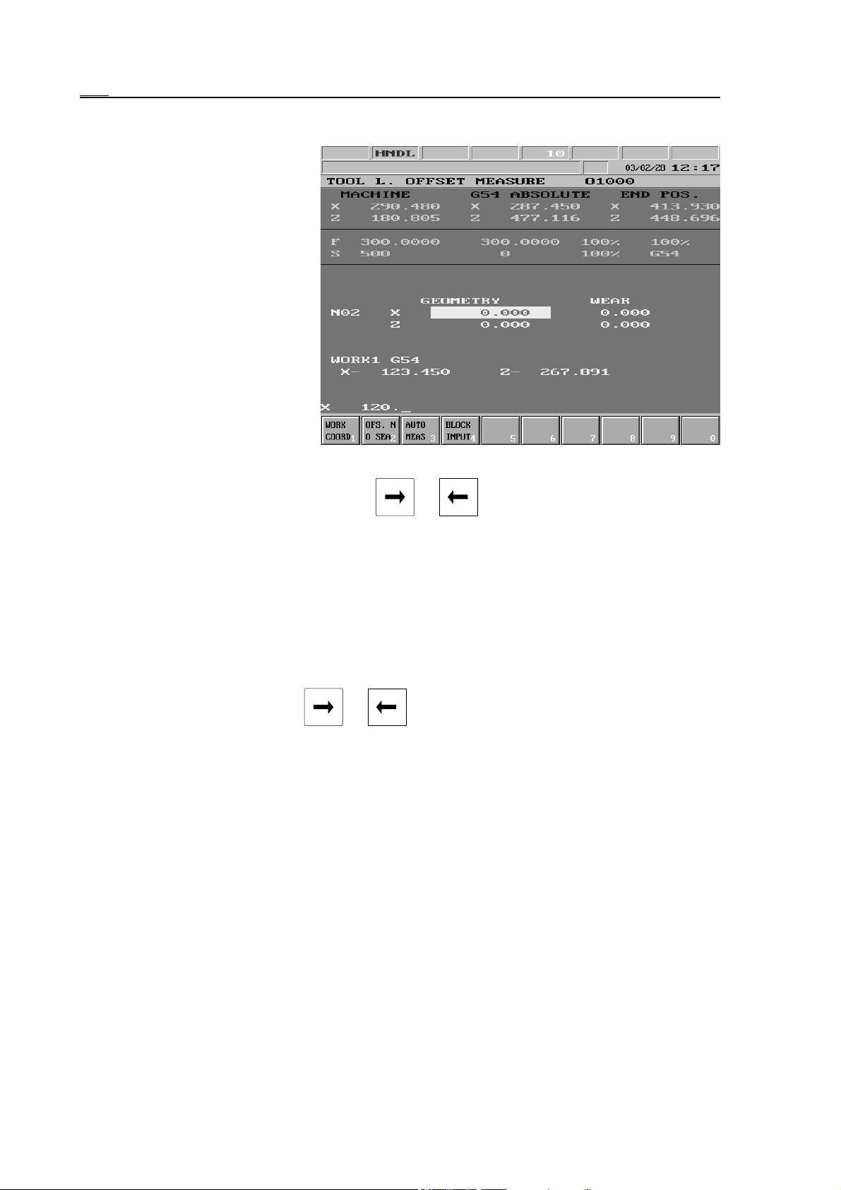
7.2.2 Tool Length Offset Measurement inside the Machine
7.2.2 Tool Length Offset Measurement inside the Machine
Tool length can be measured
also inside the machine. For
this softkey
F4
T. LENG MEASUR (tool length measurement)
of F5 OFFSETS action menu
must be selected.
Select the tool length offset
register, in which the tool length
to be stored. In order to do this
softkey F3 OFS NO SEARCH
(offset number search) must be
pressed. The offset register number, which is to be used in the
course of measurement, shall be
entered under address N in the
bottom data input line, than the
data input must be terminated by either key or .
The coordinate system, to which the tools are to be related to, needs to be selected after
pressing softkey F1 WORK COORDNT. (Work coordinate system), than the appropriate
softkey F1 G54, F2 G55 , ... The selected coordinate system is not changed to (as after the
execution of the appropriate command G54, G55, ...), but is only taken into account in the
course of measurement.
After taking cuts on X and Z axes, measuring the diameter X and length Z of workpiece cut,
the values are to be specified in the lower data input line on address X and Z. The data input
must be terminated by either key or .
The control calculates the tool length offset automatically by taking the current axis position
into account.
78
Page 79
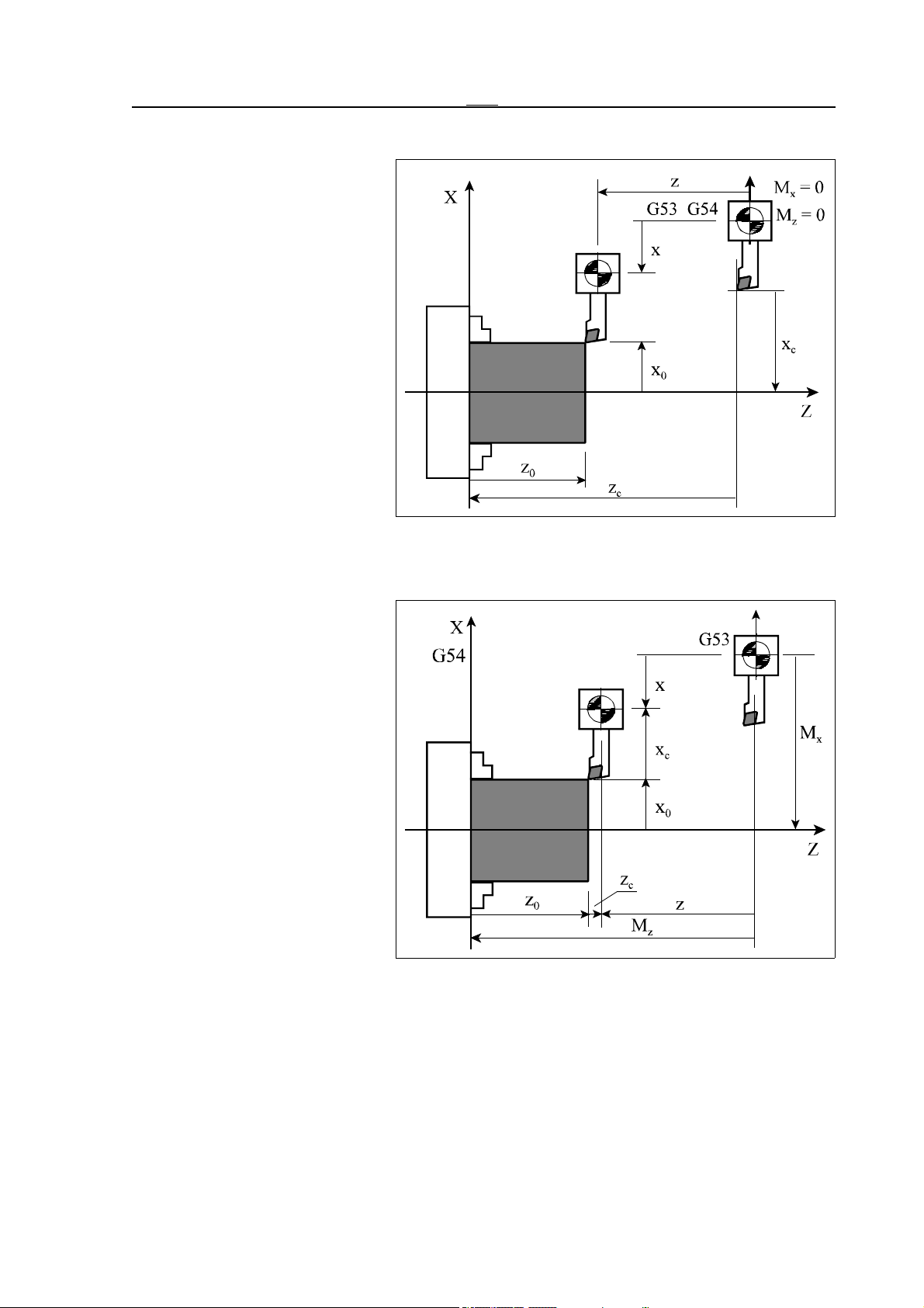
7.2.2 Tool Length Offset Measurement inside the Machine
If No Work Zero Point Offset Measurement had Taken Place Previously
If no work zero point offset had
taken place previously, the appropriate work offset of the selected coordinate system is zero
(Mx=0, Mz=0). The coordinate
values measured after cutting
and entered to control at addresses X and Z: x0, z0. The control calculates the tool length
with the help of the relation, discussed for work zero point offsets. The tool length offsets resulted contain the X- and Z-direction work zero point offsets,
as seen on the diagram.
= x – x0 – M
x
c
zc = z – z0 – M
x
z
If Work Zero Point Offset Measurement had Taken Place Previously
After entering the coordinates
the tool length is calculated with
the help of the following equation:
xc = x – x0 – M
zc = z – z0 – M
x
z
where
– xc zc: length offset calculated
by the control
– x, z: reference position of the
tool holder in the
machine coordinate system(excluding length
offset)
– x0, z0: data entered to coordi-
nates X and Z, the
known size of the
workpiece
– Mx, Mz: Work zero point offset value in the selected coordinate system.
In this case the tool length equals to the tool overhang, as seen on the diagram.
L
Note:
Values x and z of the above equation differ to position seen on position display G53, if tool
length compensation has been called (Tnnmm). In values "x, z" the called length offset is
never taken into account. Therefore before measuring it is useful to delete tool length by
means of command Tnn00, however this only makes position display more understandable.
79
Page 80
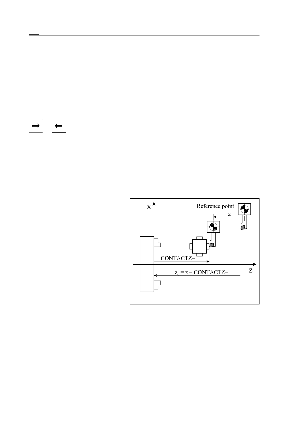
7.2.3 Automatic Tool Length Offset Measurement
7.2.3 Automatic Tool Length Offset Measurement
Tool length offsets can also be measured automatically, provided the machine is mounted
with a tool offset sensor. Select screen F4 T LENG MEASURE (tool length measurement) in
screen menu of F5 OFFSETS.
Switch control to JOG mode, than change the tool to be measured.
Move the tool tip near to the tool sensor by the use of jog buttons.
The length offset register in which the size of the tool is to be stored must be specified after
F3
the action menu button is pressed. Press softkey
OFS NO SEARCH (offset number search).
The number of the offset register to be used for the tool measurement must be written at
address N in the data input line than the data input must be terminated by means of button
or . In case parameter 1353 OFFSNL is set to 1 the cursor moves automatically to
the offset register the number of which corresponds to the number of tool activated.
Press softkey F3 AUTO MEAS after the action menu is pressed.
Touch the tool sensor by moving axis with the appropriate jog button. In this case the speed
of movement is always the value defined at parameter 8022 G37FD independent of the
override switch state. Even 0% state of the override switch is ineffective, the jog button must
be released in order to stop.
As the tool tip touches the appropriate button of the tool offset sensor, the movement stops
and only movement in the contrary direction is possible. The control calculates the tool length
offset value automatically at the moment when the sensor has been pressed.
The tool offset sensor enables
measurement in all four directions
(X+, X–, Z+, Z–). It has buttons in all
four directions, their posit ions must be
calibrated and stored at parameters
previously. The parameters are:
8081 CONTACTX+,
8082 CONTACTX–,
8083 CONTACTZ+,
8084 CONTACTZ–.
The control subtracts value of the appropriate CONTACT parameter from
the current position related to the reference point and the difference is referred to as tool length offset at the
moment of touch. On the diagram the
position of the Z– button of the sensor is defined to chuck’s plane. The control calculates the
z-direction length offset with the help of the equation below:
zk = z – CONTACTZ–
where: zc: the calculated tool length offset
z: position of the tool holder base point according to the reference point
CONTACTZ–: position of Z– button of sensor registered at parameter
Warning!
The work zero point offset must always be measured after the use of automatic length offset!
80
Page 81

7.2.4 Calibrating Tool Offset Sensor
7.2.4 Calibrating Tool Offset Sensor
The tool offset sensor calibration means the definition and storage of button positions at parameters CONTACT. The sensor can be calibrated in two ways.
The first possibility is that the button positions of the sensor are defined in a coordinate system
set by the user, e.g., a coordinate system fixed to the chuck. In this case the values of tool
length offsets contain the zero point offset according to the reference point.
The other possibility is that the but t on positions of the senso r are defined according to the
reference point. In this case the tool length offset value equals to the tool overhang.
Warning!
Parameters 8081 CONTACTX+ and 8082 CONTACTX– must always be specified in radius
independent of the default interpretation being in diameter or radius in the control. All
CONTACT parameters must be defined in the double of output increment system, i.e. for
example in case of metric machine and INCRSYSTB=1 it is in :m without decimal point.
Before the start of the calibration clear all tool length offsets, work zero point offsets as well
as all CONTACT parameters.
81
Page 82
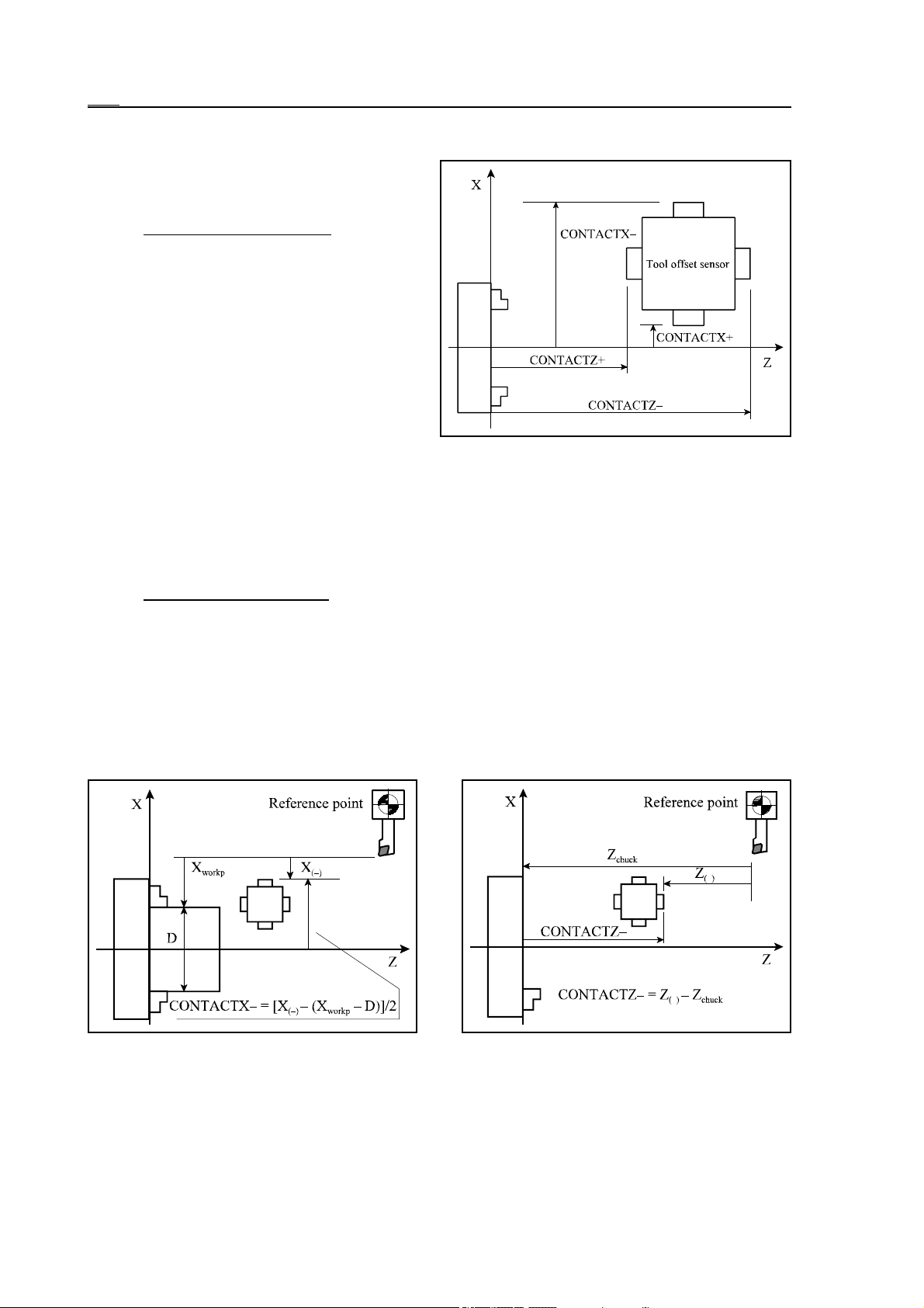
7.2.4 Calibrating Tool Offset Sensor
Calibrating the Sensor to the Coordinate System of Chuck
The enclosed diagram beside shows the interpretation of CONTACT parameters.
Calibrating in X direction
Turn an optional workpiece, leave the
workpiece in Z direction and read the machine position of X axis, indicated with
on the diagram below.
X
workp
Measure the workpiece diameter indicated
with D on the figure.
Execute an automatic tool length measure as
discussed in the previous chapter in X–
direction. Read the selected X offset register
value indicated with X
on the diagram.
(–)
Calculate and enter the value of parameter CONTACTX– with the help of the following
equation:
CONTACTX– = [X
(–)
– (X
workp
– D)]/2
In the above equation X position display is supposed to be in diameter.
The position of X+ button can also be defined by means of the above procedure
Calibrating in Z direction
Define the position of tool tip according to the chuck indicated with Z
on the diagram
chuck
below.
Execute an automatic tool length measurement as discussed in the previous chapter in Z–
direction. Read the selected Z offset register value indicated with Z
on the diagram. Calculate
(–)
and enter the value of parameter CONTACTZ– with the help of the following equation:
CONTACTZ– = Z
(–)
– Z
chuck
The position of Z+ button can also be defined by means of the above procedure.
82
Page 83
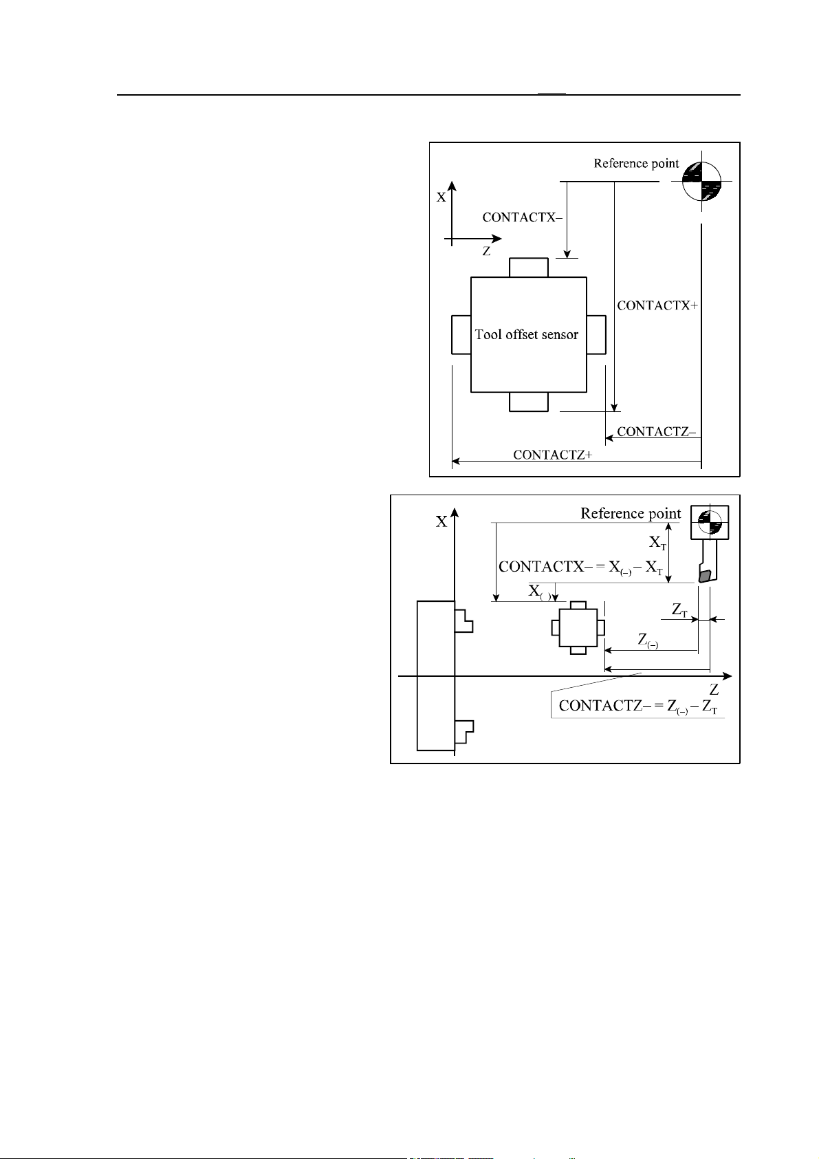
Calibrating the Sensor to Reference Point
The figure beside shows the interpretation of
CONTACT parameters.
Let us examine the following example.
Place a tool, the overhang of which is known
in the tool holder. The tool overhang is
indicated with XT, ZT on the diagram below.
Execute an automatic tool length measurement as discussed in the previous chapter.
On the diagram it is in directions X–, Z–.
Read the selected X, as well as Z offset register values indicated with X
(–)
, Z
on the
(–)
diagram. Calculate and enter the values of
the CONTACT parameter with the help of
the following equation:
CONTACTX– = X
CONTACTZ– = Z
(–)
(–)
– X
– Z
T
T
7.2.4 Calibrating Tool Offset Sensor
The procedure can also be applied for
the other buttons.
83
Page 84
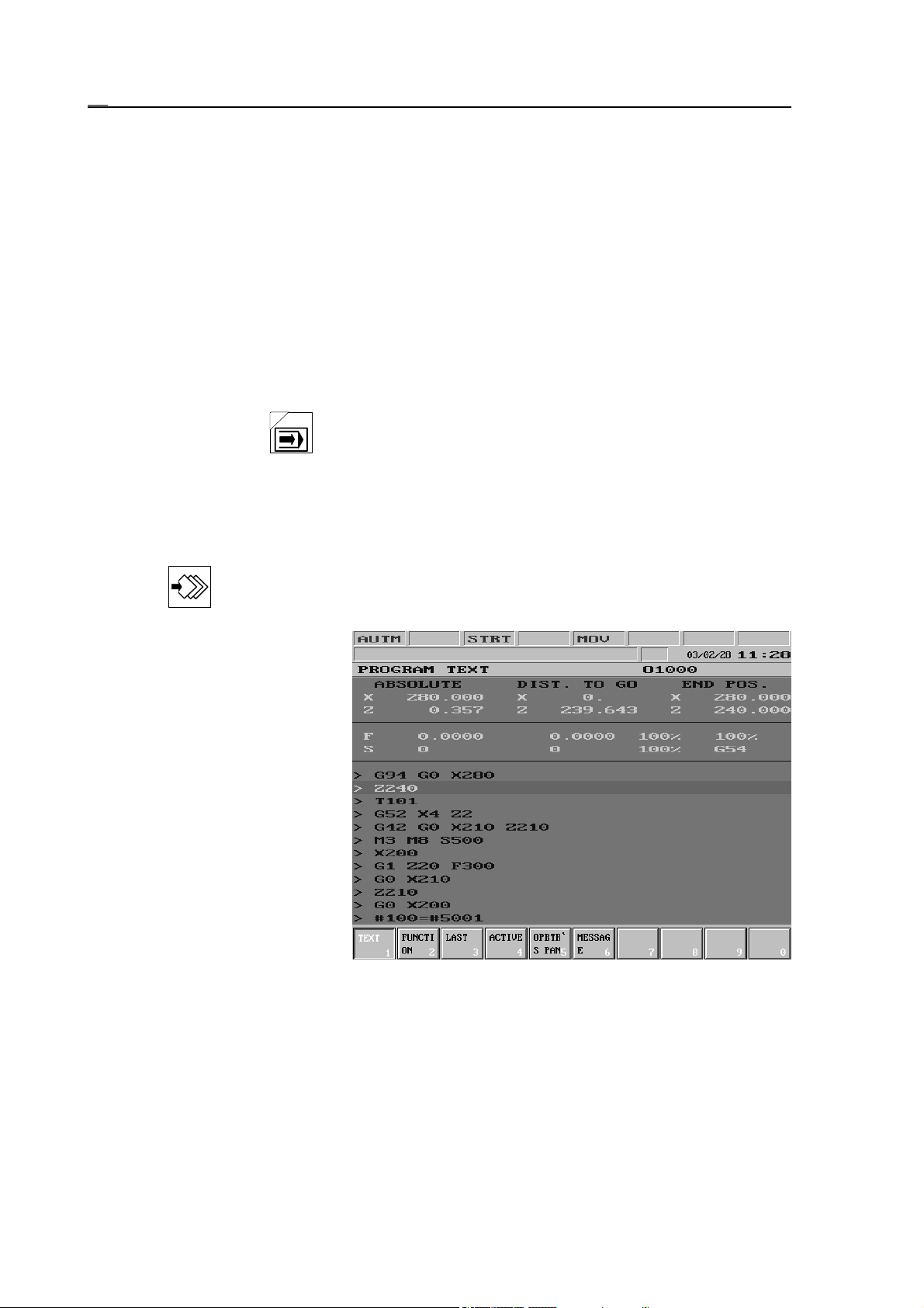
8.1 Automatic Mode
8 Modes of Automatic Operation
The modes of automatic operation are:
Automatic
Edit
Manual Data Input
8.1 Automatic Mode
Program execution in automatic mode can only be done upon power-on state of the machine,
i.e. when there is no EMG (emergency stop) state in the rightmost field (general NC stat e) of
status bar.
If the machine is mounted with NCT machine control board the automatic mode can be
switched on by pressing button.
The automatic mode is the operation mode, executing part programs. The part program to be
executed can be in the memory of control, as well as in external device, e.g., in a computer.
Whether the program to be executed is to be loaded from the memory or from an external
device, can be determined, after selecting DIRECTORY screen. After pressing the action
menu key RUN action menu must be selected. Afterwards the process corresponds to
what have been discussed in chapter Program directory actions.
If the program is executed from
the memory, caption AUTM can
be seen in the first field of status
bar (first operation mode state),
while in case of an external device it is the caption AUTD
(DNC). The number of the
program, selected for automatic
execution appears at the end of
line containing the name of the
current general displaying area.
8.1.1 Program Execution in DNC
DNC connection is realized through RS-232C serial interface. Keep an eye on setting the same
parameters (baud rate, number of stop bits ect.) on both the transmitter and the receiver side.
There may be three kinds of DNC connection.
Simple connection is realized between control and external device upon selection of action
DNC of RUN menu. The connection has no protocol, the data can be sent by any serial port
driver.
In case of selecting action DNC NCT, program dnc-plus.exe (product of NCT Kft) needs to be
84
Page 85

8.1 Automatic Mode
executed on the transmitter side. Program dnc-plus.exe can be executed on IBM PC or on a
compatible computer. It ensures connection between transmitter and receiver with protocol. Its
advantage over simple DNC connection is that it calculates the checksum by each program
block and sends it to control. If the receiver detects an error, it asks for repetition and the
transmitter sends the block again. Of this, the operator notices nothing what so ever, for it
proceeds automatically. Contrary to simple DNC connection this method makes data transfer
very safe, the possibility of mistaking (i.e., control receives false command due to error in data
transfer channel) is minimal.
If the option FEW (Floppy Ethernet Winchester) is integrated into the control that is really an
integrated PC (Personal Computer), then also action DNC FEW can be selected. Then
program execution happens from the PC.
The programs sent in DNC must meet the following requirements:
– no divergence command can be used in main program (i.e. in the program, which is
transmitted from external device), such as GOTO or M99 Pnnnn,
– subprogram or macro call is possible with the restriction that the subprogram or macro
program must be in the control memory, it cannot be on external device.
Machining Start and Stop
The machining starts with the START button and stops with the STOP button in effect. If no
program is selected for execution in automatic mode, and control is not in DNC state, the error
message NOT EXISTING PROGRAM is displayed when starting automatic mode.
85
Page 86
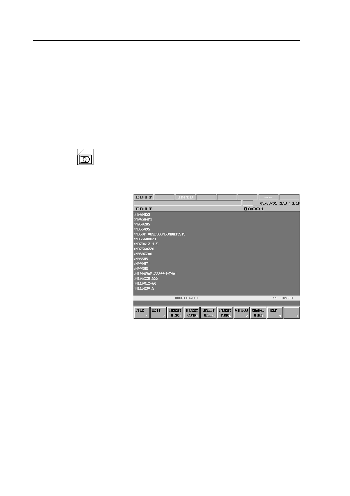
8.2 Edit Mode
8.2 Edit Mode
In case there is no PLC program or PLC program or parameter area is damaged in control, edit
mode is activated after turning the power on. .
Edit mode is indicated by caption EDIT in the leftmost field of the status bar. The following
actions can only be executed in edit mode:
– editing, as well as loading or saving through serial input the parameter area,
– loading PLC program to control,
– editing programs selected for execution in automatic mode and interrupted during execu-
tion, as well as editing sub-programs and macros called from this main program, on
condition that those are under processing.
If the machine is mounted with NCT machine control board the edit mode can be switched on
by pressing the button.
Editing Programs under Automatic Execution
Programs (main programs and
sub-programs under automatic
execution are indicated by exclamation mark ! standing before
their names on DIRECTORY
screen. These programs can be
edited with the following restrictions.
If automatic mode is interrupted
during execution, switch-over to
edit mode is done and the screen
EDIT is displayed, the control
always displays the currently
interrupted program, independent of the highlighted program in
the list of the directory (indicating the background editing). Editing can be done, beginning with the block after the interrupted program block. The control disqualifies editing of the interrupted block and of previous
blocks. If editing of such a block is selected by means of cursor, two arrows 67, pointing at
each other indicate in the 7th status field, that this block cannot be edited.
The same situation occurs, if execution of a subprogram or macro is interrupted. In this case
the subprogram or macro can be modified by opening edit mode with the above restrictions.
86
Page 87
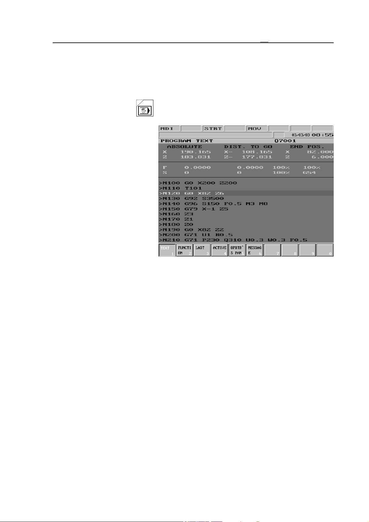
8.3 Manual Data Input Mode
8.3 Manual Data Input Mode
Program execution in manual data input mode can only be done upon power-on state of the
machine, i.e. when there is no EMG (emergency stop) state in the right most field (general NC
state) of status bar.
If the machine is mounted with NCT machine control board the manual data input mode can be
switched on by pressing the button.
In manual data input mode all
part programs in control memory, that is not selected for automatic execution can be executed.
The program to be executed can
be selected after displaying the
DIRECTORY screen. After
pressing the action menu key
action menu RUN must be
selected. Than the process corresponds to what have been discussed in chapter “Program directory actions”.
By opening the operation mode
caption MDI appears in the
leftmost field of status bar. The
program starts by the use of the START button, while with the STOP button the execution can
be stopped. By pressing START button error message
NOT EXISTING PROGRAM
is displayed if no program is selected for execution in manual data input mode.
Differences between Automatic and Manual Data Input modes
– In manual data input mode only programs in memory can be executed, therefore in this case
DNC transfer is not possible!
– In manual data input mode the program cannot be continued from the interruption point
(contrary to automatic mode). This means that the program is always executed from
the beginning when the operation mode is activated.
– In program selected for manual data input mode block number cannot be searched for.
Among others the manual data input mode can be used for simplifying interventions frequently
occurring while machining. In this case there is no need to enter and execute one or more
blocks by means of single block input, but the process needed is written down in a program.
Switching over from aut omatic to manual data input and starting the process by interrupting
automatic mode can be done any time. For example in the case of tool break a program, which
stops spindle and switches off coolant, takes out the tool and stands to a position the
intervention from which is easy, can be started in manual data input mode. Another way to use
it is when a size needs to be checked on the work during machining, the automatic mode can
be interrupted and a measuring cycle started in manual data input mode. After the needed
process is done the automatic mode can be returned and the machining continued.
87
Page 88

8.3 Manual Data Input Mode
In manual data input mode, during program execution, the operation of the following functions
corresponds to that in automatic mode:
– Single block execution
– Conditional STOP
– Conditional block
– Dry run
– Locking possibilities.
88
Page 89
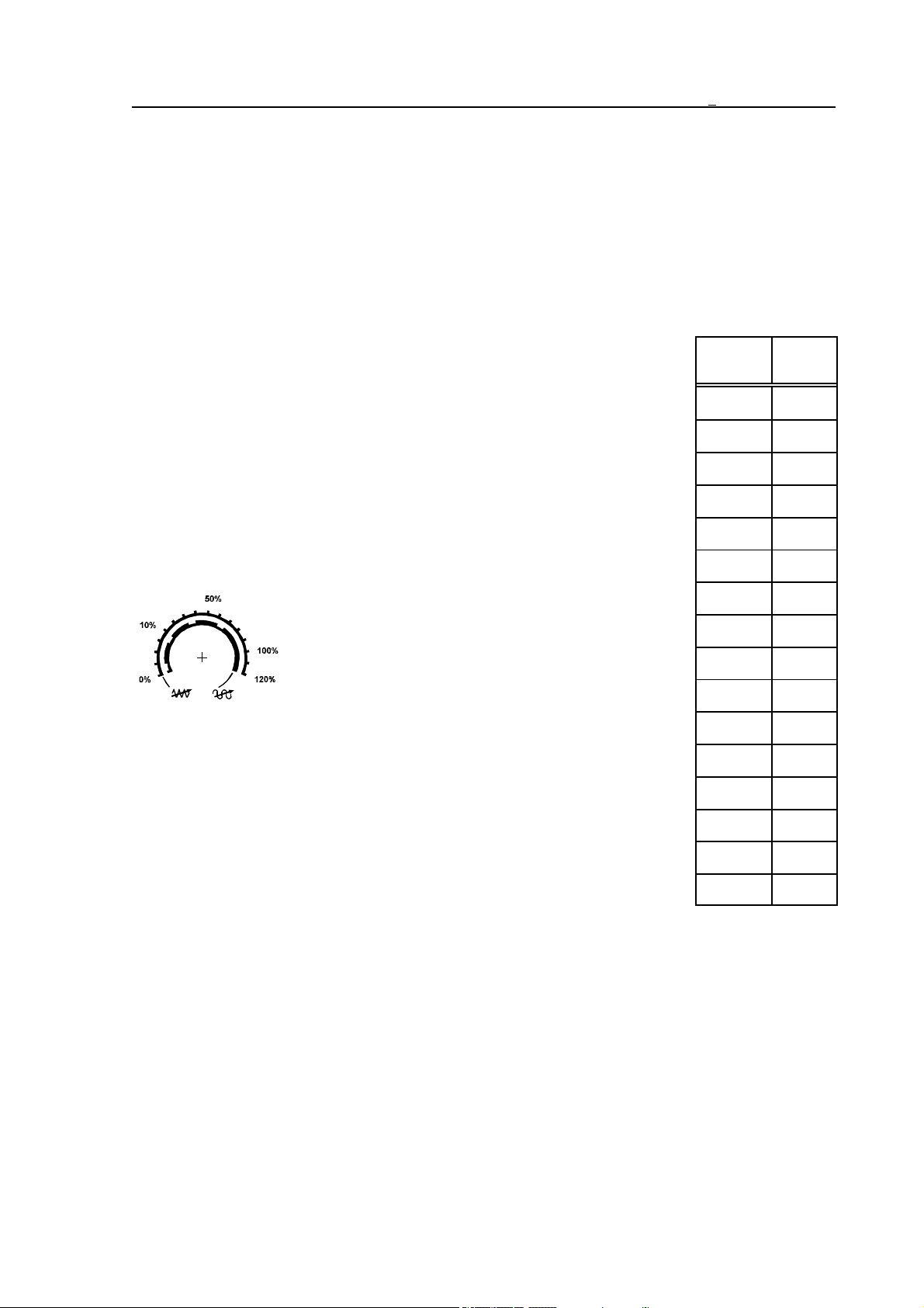
9 Override Switches
The control can operate three override switches:
– the feedrate,
– the rapid traverse, and
– the spindle speed
override switches.
9.1 Feedrate Override Switch
9 Override Switches
The feedrate override switch has 16 positions. The feedrate switch
determines, by how many percent of the programmed feedrate (F) should
switch
state
the axes be moved. The diagram beside shows the position of the switch
and the percentage belonging to the position. Position 0% stops the
movement of not only the feed, but also of rapid traverse movements.
In basic configuration feedrate override switch can be selected on
OPERATOR’S PANEL or POSITION screen. After pressing the action
menu key, action F4 % must be selected. This way the percentage can be
decreased (by means of softkey F–), as well as increased (by means of
softkey F+).
The NCT machine control board is mounted with a
16-position rotary switch. In this case in place of
the above mentioned override adjustment with
softkeys this feedrate switch can be used.
The feedrate switch position is interpreted in jog
mode on the basis of parameter adjustment. If the
value of parameter 1372 JOGFEED is 0, the speed of jog is the modal
value F. If the value of parameter 1372 JOGFEED is 1, the control
registers the speed fixed in table on the basis of feedrate switch position.
(See table of jog mode.)
In the following cases the feedrate switch is ineffective:
– G63, i.e. state of override disabled,
– at the values of variable #3004 listed in programmer’s manual, and
– during thread cutting G33, G34, G76, G78 and tapping cycles G84.1,
G84.
In these cases the control always supposes 100% independent of switch position.
%
10
21
32
45
510
620
730
840
950
10 60
11 70
12 80
13 90
14 100
15 110
16 120
89
Page 90
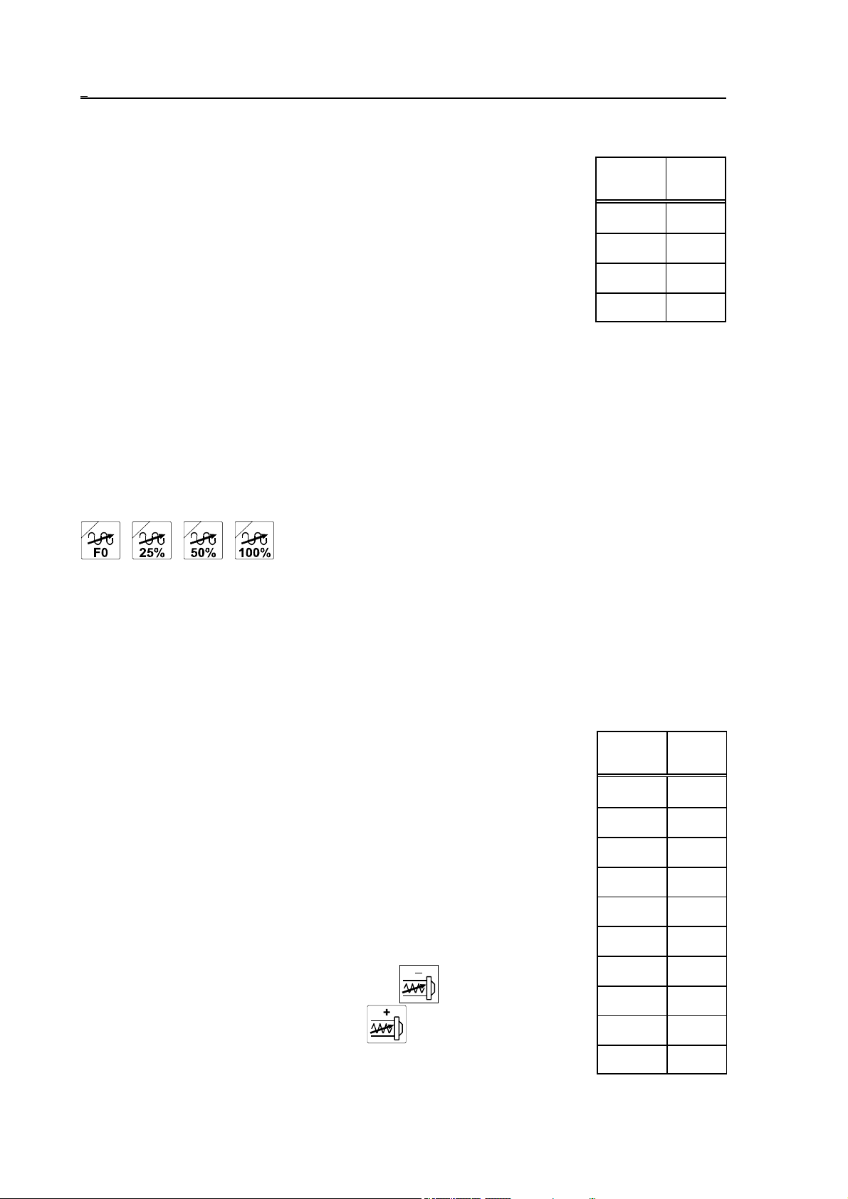
9 Override Switches
9.2 Rapid Traverse Override Switch
The rapid traverse override switch determines, by how many percent of
the rapid traverse rate defined in the parameter should the axes be
moved. The diagram beside contains the switch positions and the
percentages belonging to the positions.
switch
state
1F0
%
F0 is a percentage fixed at parameter 1204 RAPOVER. Its practical
225
value is 10% or less.
350
If the value of parameter 1204 RAPOVER is 0 the rapid traverse
override values (depending on the PLC program) are the same discussed
4 100
earlier at feedrate override in the range of 0, 1, 2, 5, 10, 20, ..., 100%.
Consult with the machine tool builder on details.
Feedrate override switch position 0% stops the rapid traverse movements as well, so there is
no need to have a rapid traverse position 0%.
In basic configuration, rapid traverse rate override switch can be selected on OPERATOR’S
F4
PANEL or POSITION screens. After pressing the action menu key, action
% must be
selected. This way with the help of softkeys R–, R+ the percentage can be decreased (by means
of softkey R–), as well as increased (by means of softkey R+).
If the machine is mounted with NCT machine control board the
rapid traverse override value can be selected with four buttons
optionally.
L
Note:
The control can also take over % value of rapid traverse rate from feedrate override switch.
For details turn to the machine tool builder for an information material.
9.3 Spindle Speed Override Switch
The spindle speed override switch has 11 positions. The switch determines, by how many percent of the programmed spindle revolution (S)
should the spindle be rotated. The diagram beside contains the switch
positions and the percentages belonging to the positions.
In basic configuration, spindle speed override switch can be selected on
OPERATOR’S PANEL or POSITION screens. After pressing the
action menu key, action F4 % must be selected. This way with the help
of softkeys S–, S+ the percentage can be decreased (by means of
softkey S–), as well as increased (by means of softkey S+).
Three buttons are mounted on the NCT machine control board. In this
case in place of the above mentioned override adjustment with softkeys
the three buttons can be used. With the button in effect the value
is decreased, while by pressing the button it is increased. By
90
switch
state
150
260
370
480
590
6 100
7 110
8 120
9 130
10 140
%
Page 91

9 Override Switches
pressing the button the control restores the programmed 100% rate.
During thread cutting G33, G34, G76, G78 and tapping cycles G84.1, G84 the spindle speed
override switch is ineffective. The control registers 100% independent of the switch position.
91
Page 92
10 Program Execution Start and Stop
10 Program Execution Start and Stop
The program execution is started by the use of the START button.
The program execution can be stopped by means of the following functions and keys:
– with the STOP button,
– with the RESET key,
– at the end of block execution in the single block mode ,
– after executing programmed stop command M00,
– as the effect of conditional stop command M01, if optional stop switch is on,
– after executing program end commands M02, M30.
10.1 Starting Program Execution
In the following cases the program execution is started by pressing START button :
– in jog, incremental jog or manual handle feed mode, after single block has been entered and
terminated,
– in automatic mode, if program is selected for execution from memory or DNC,
– in manual data input mode, if program is selected for execution.
Error message
NOT EXISTING PROGRAM
is displayed by pressing START button, if no program is selected for execution. START state
is indicated by caption STRT in the 3rd field of status bar.
10.2 Feed Stop
During program execution by pressing STOP button START state is cancelled. The
axes decelerate and stop. The execution of functions (M, S, T, B) in the given block is
continued till the end of block. STOP state is indicated by caption STOP in the 3rd field of the
status bar.
In the following cases the STOP button is ineffective:
– G63, i.e. state of override inhibit,
– values of variable #3004 listed in programmer’s manual, and
– during thread cutting G33, G34 and tapping cycles G84.1, G84.
10.3 RESET
If reset key is pressed during program execution, START or STOP state is canceled.
The axes decelerate and stop, even if control executes operation, where the use of feedrate
override switches and STOP button is ineffective (e.g.: G33, G34, G76, G78, G84.1, G84).
92
Page 93
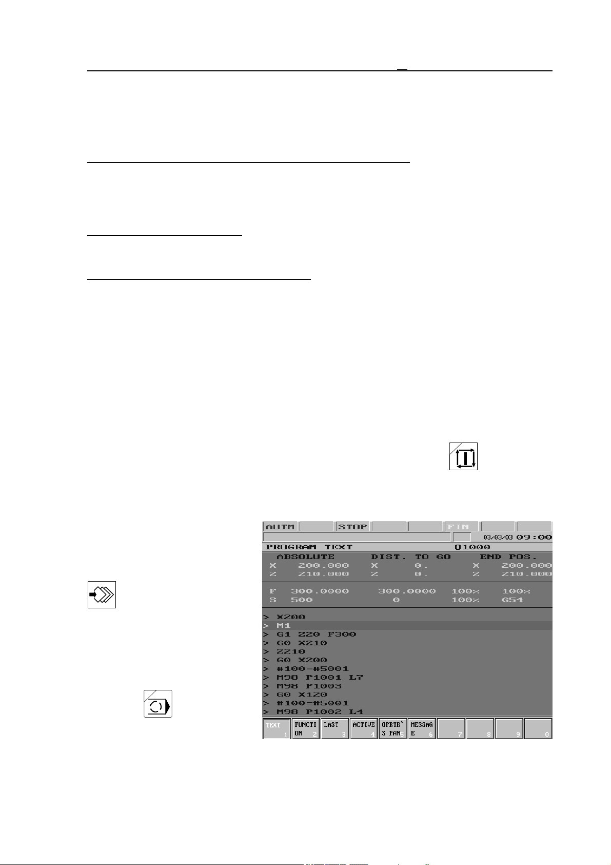
10 Program Execution Start and Stop
At the same time some global messages are also cleared from the message field of the status
bar.
The PLC program (generally) stops spindle rotation and suspends operation under execution.
Besides RESET key has other effects in the different modes as well.
In Automatic Operation in Case There is No INTD State Yet: If RESET key is pressed in
automatic operation and there is no INTD (interrupted) state yet, caption INTD is
displayed in the 3rd field of status bar. This means, that automatic operation is interrupted. Afterwards program execution can be continued from the block, which has
been interrupted.
In Manual Data Input Mode: If RESET key is pressed in manual data input mode, program
execution is interrupted and it cannot be restarted from the interruption point, only
from the beginning.
In Case of the Execution of a Single Block: If RESET key is pressed during the execution of
a single block the block is cleared from the buffer. If the same block needs to be
executed again, the single block input must be terminated once more.
In case automatic mode is being selected, INTD state is in effect, no message is being
displayed in global message line and RESET key is pressed, INTD state is cancelled and the
program executor goes to the first line of the program selected for automatic execution, i.e.
machining begins from the beginning by pressing START button. INTD state is cleared and
control registers default status fixed at parameters.
10.4 Programmed Stop: M00
If control goes to code M00 during program execution, it executes block containing code
M00, than STOP state is assumed and the machining stops. With START button the
machining is continued.
10.5 Conditional Stop: M01
Conditional stop state can be
selected on OPERATOR’S
PANEL or POSITION screens.
After pressing the action menu
key F5 CONDITIONS
action menu must be selected,
than switch COND. STOP (conditional stop) needs to be
pressed.
If NCT machine control board is
used select button.
If control runs to code M01
during program execution, it
93
Page 94
10 Program Execution Start and Stop
executes block containing code M01 if switch COND. STOP is on, than STOP state is
assumed and the machining stops. With START button the machining is continued.
Nothing happens if switch COND. STOP is off.
10.6 End of Program: M02, M30
Codes M02, M30 indicate the end of main program. By its use the machining stops, START
state is canceled. In the course of program execution from memory listing goes to first block of
main program, from where the machining can be started from the beginning by the use of
START button .
Even if program end code is not entered to the end of main program, with symbol % in effect
the above process is affected, except for PLC actions belonging to the codes M02, M30, for
example spindle stop and coolant off are not executed.
94
Page 95
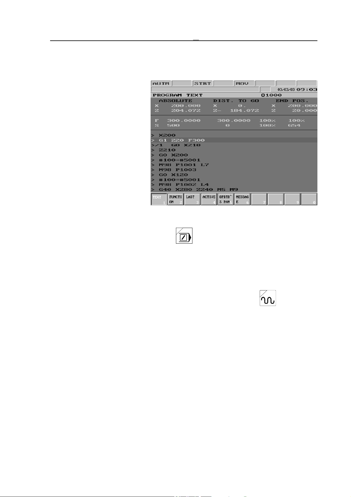
11 Intervention in the Course of Program Execution
11 Intervention in the Course of Program Execution
11.1 Conditional Block Skip
If at the beginning of block conditional block skip /n is programmed (n means the number
of the conditional block switch),
than
– if switch No. n is on, it skips
block,
– if switch No. n is off, it exe-
cutes block.
The conditional block switch
No. 1 can be reached on
OPERATOR’S PANEL or
POSITION screens. After
pressing the action menu key,
F5
CONDITIONS action menu
must be selected, than switch
COND. BLOCK (conditional block) needs to be pressed.
If NCT machine control board is used select button.
The control can handle another 8 conditional block switches (altogether 9). These switches can
be optionally used.
11.2 Increasing Feedrate by Means of Rapid Traverse Jog Button
If axes are moved during program execution and rapid traverse jog button is pressed,
the control increases feedrate, if rapid traverse jog button is released, it resets the programmed
feedrate.
The measure of acceleration is determined by the value fixed at parameter 1371 FMULT. The
programmed value is multiplied by the number fixed at parameter, and the result is activated as
feedrate. If the value of parameter is 1 the feedrate remains unchanged when pressing rapid
traverse button, if the value is e.g. 2 it is doubled.
95
Page 96
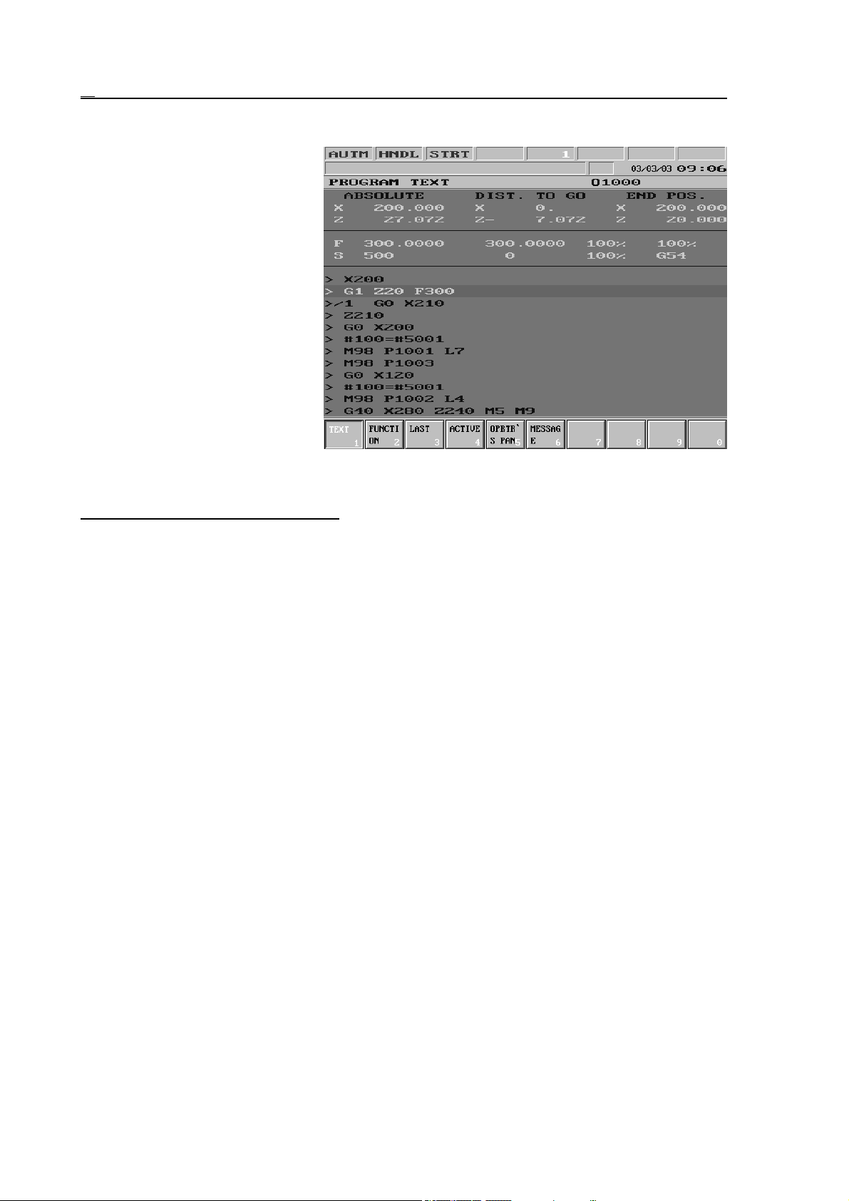
11 Intervention in the Course of Program Execution
11.3 Intervention by Means of Manual Handle in Automatic Operation
The manual handle operation can
also be turned on parallel to the
automatic operation. In this case
in the leftmost field of status bar
caption AUTM or AUTD
indicating automatic operation
can be seen, depending on where
the program execution takes
place from. At the same time in
the 2nd field of status bar caption
HNDL appears, indicating the
manual handle operation.
By the use of the manual handle
a movement can be overlapped
to the movement of axes defined
in the program. The tool path
formed will differ from the one defined in the program.
The rules of operation are as follows:
– The rules of selecting axis and increment correspond to the ones discussed by manual handle
mode.
– The speed of intervention coming from the manual handle is added algebraically to the speed
resulting from interpolation, however the speed realized cannot be over the maximum
feedrate permitted, that is registered on the given axis.
If e.g. the maximum feedrate is 2000 mm/min and the selected axis is moved in
direction + by 400 mm/min, the speed coming from manual handle can be 1600
mm/min in direction +, or 2400 mm/min in direction –.
If the speed realized is over the maximum speed permitted, the control throws away the
useless pulses, in contrast to the normal manual handle mode.
– Movement is made even in feedrate override state 0%.
– As the effect of intervention by means of manual handle the direction can be reversed.
– Movement is not made in the following cases:
State G00, or other states of rapid traverse movement, as, e.g., positioning phase of
canned cycle, G28, G53, etc. even if no movement command is programmed on the
given axis.
STOP state.
96
Page 97
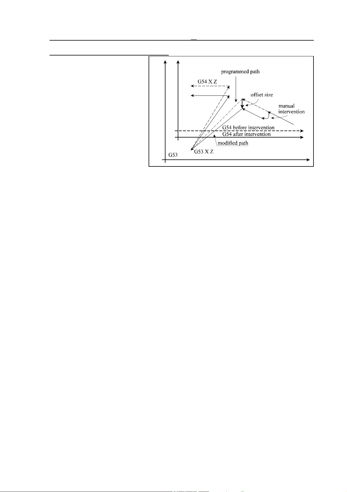
11 Intervention in the Course of Program Execution
Effect of intervention to coordinate system
– The manual handle pulses are
also added to the offset
on the appropriate axis in
the common work zero
point offset registers.
This way all the works
and local coordinate systems are being shifted.
– Naturally this does not influ-
ence the machine coordinate system. In case of
G53 or G28 the axis always moves to the appropriate position.
– The value rotated by manual
handle cannot be seen on
the display showing the current position in compliance with the above discussed.
If one of the common work zero point offsets is other than zero an exclamation mark ! can be
seen in the 7th status field.
97
Page 98
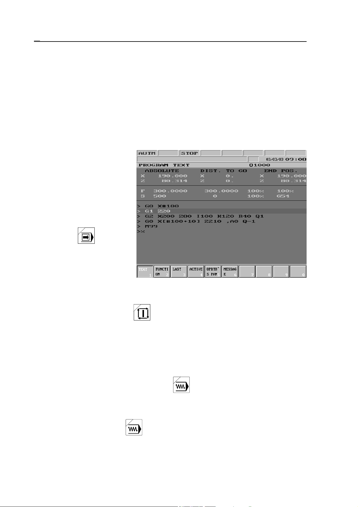
12 Debugging Part Program
12 Debugging the Part Program
The following functions help the testing, debugging of the part program:
– single block execution,
– dry run,
– locking possibilities and
– test run.
These functions are not operation modes, but conditions influencing the program execution in
automatic mode.
12.1 Single Block Execution
Single block execution can be
selected on OPERATOR’S
PANEL or POSITION screens.
After pressing the action menu
key, F5 CONDITIONS action
menu must be selected, than
softkey SINGLE BLOCK needs
to be pressed.
If NCT machine control board is
used select the button.
Single block execution can be
done in automatic and manual
data input modes. The control
stops (STOP state) after the execution of each block.
An exception to that when thread cutting blocks G33 follow each other or suppression of
single block execution has been programmed by giving value #3003=1. The machining
continues with the START button .
12.2 Dry Run (All Feedrates at High Speed)
Switch DRY RUN can be reached on OPERATOR’S PANEL or POSITION screens. After
pressing the action menu key, F5 CONDITIONS action menu must be selected, than softkey
DRY RUN needs to be pressed.
If NCT machine control board is used select the button.
When the switch is on all feeds move at high speed, fixed at parameter. It executes every
movement at feedrate interpreted in dimension per minute, independent of whether state G94
or G95 is programmed .
Generally the DRY RUN button can be activated only in one of the manual modes
provided the axes are in stopped state. For details turn to the machine tool builder for an
information material.
98
Page 99
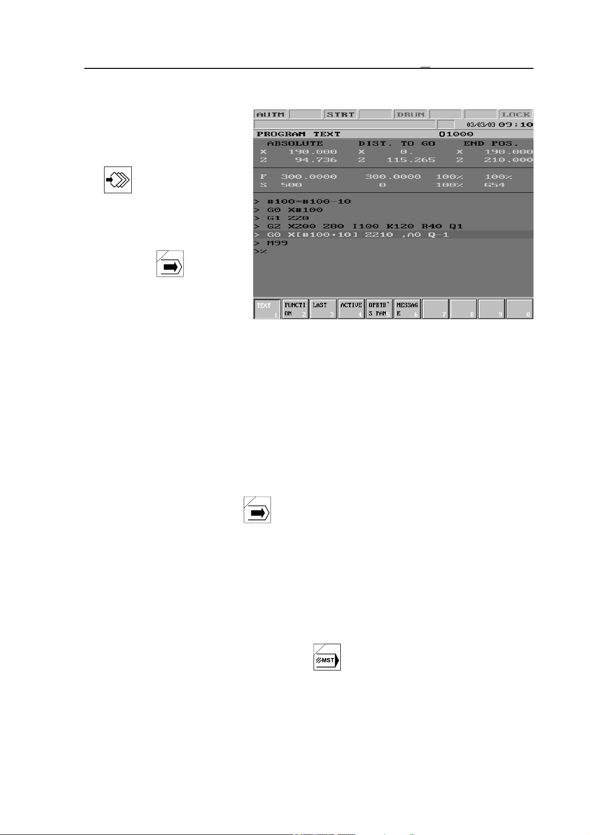
12 Debugging Part Program
12.3 Machine Lock Function
Switch MACHINE LOCK can
be reached on OPERATOR’S
PANEL or POSITION screens.
After pressing the action menu
key F5 CONDITIONS
action menu must be selected,
than softkey MACHINE LOCK
needs to be pressed.
If NCT machine control board is
used select the button.
The locked state of the machine
is indicated by caption LOCK in
the 8th field (general NC state)
of the status bar.
If the switch is on:
– the interpolator does not give out any command to the position control loop on either axis,
as well as
– no function is executed by the PLC at all.
Functions machine lock and dry run can be combined, i.e., both can be switched on at the same
time. The POSITION screen and the GRAPHIC POSITION screen show the path already
drawn. If switch dry run is on, the speed is high, if it is off, the speed is the programmed
feedrate.
If machine lock is switched off, the momentary axis positions can be seen again on the
POSITION screen of control.
L
Note:
Generally key MACHINE LOCK can be switched in one of the manual modes in case
the axes are in STOP state For more turn to the machine tool builder for an information
material.
12.4 Other Locking Possibilities
Other locking possibilities may be at disposal optionally. These are as follows:
Function Lock
This means, that the control does not execute any function sent to PLC (M, S, T, B ect.)
If NCT machine control board is used select the button.
Axis Lock
The axes can be locked separately. In this case the locked axis (axes) does (do) not move,
while the others do.
99
Page 100
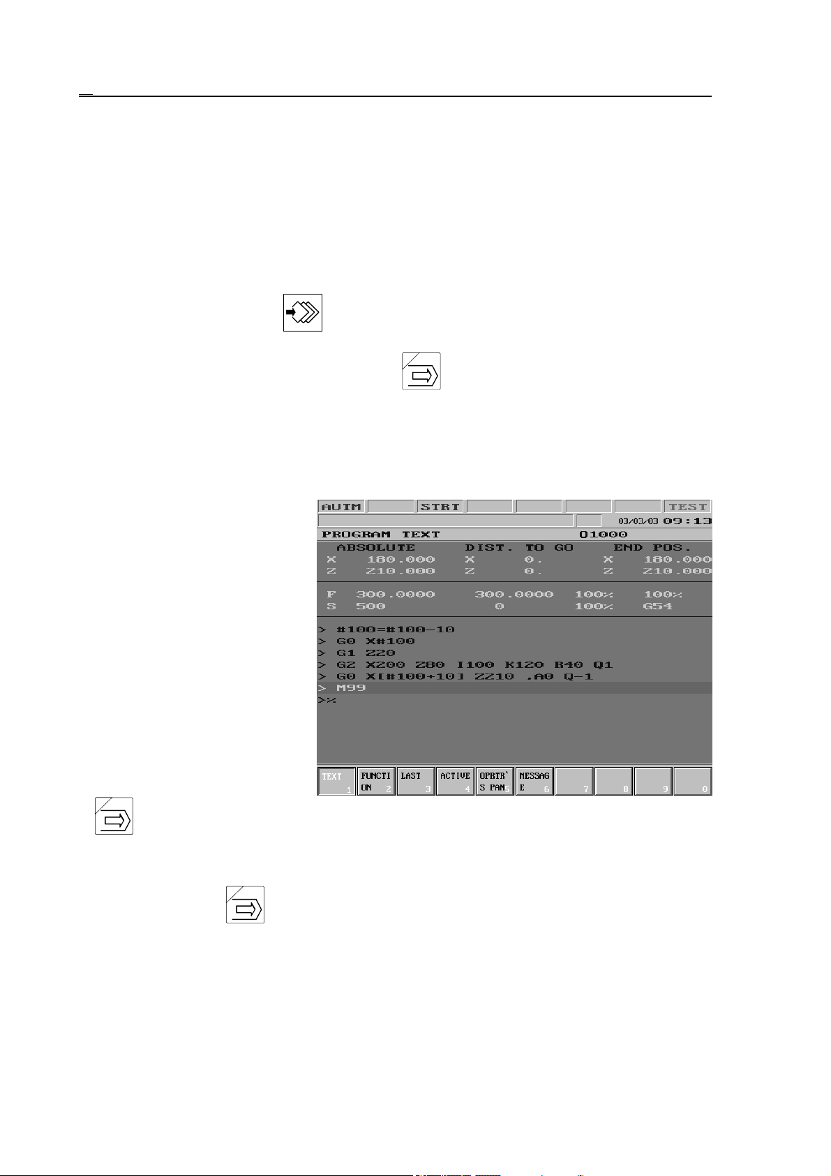
12 Debugging Part Program
The different function and axis locking possibilities can be co mbined optionally. An axis, e.g. Z
axis and the functions can be locked simultaneously.
L
Note:
About the different locking possibilities turn to the machine tool builder for an information
material.
12.5 Test Run
Softkey TEST can be reached on OPERATOR’S PANEL or POSITION screens. After
pressing the action menu key F5 CONDITIONS action menu must be selected, than
softkey TEST needs to be pressed.
If NCT machine control board is used select the button.
The TEST state is indicated by caption TEST in the 8th field of the status bar.
When the key is activated:
– the interpolator does not command any movement on any axis towards the position control
loop, and
– no function is executed by the PLC.
The TEST state can be applied for
the syntactic and graphic test of
programs. The program execution
(the interpolation) is much faster
than it is in case of the simultaneous switched on state of
MACH LOCK and DRY RUN.
The position display and the
graphic position display show the
path done.
If button TEST is
inactivated, than the current axis positions can be seen again in the position display of control.
L
Note:
Generally the TEST button can be switched in one of the manual modes in case the
axes are in stopped state. For more turn to the machine tool builder for an information
material.
100
 Loading...