

Page 1
Cirrus LT Plus
User Guide
TZ-251G
Computing Innovations.
v1.2 May 16, 2016
Page 2

Contents
Icon Glossary .............................................................................................................................................5
Safety Instructions ...................................................................................................................................6
Battery Safety and Tips ........................................................................................................................... 7
Introduction ..............................................................................................................................................8
Chapter 1: Before you start .....................................................................................................................9
Package contents .............................................................................................................................................9
Components ....................................................................................................................................................10
Front view ................................................................................................................................................11
Right View ................................................................................................................................................ 11
Left view ................................................................................................................................................... 11
Bottom view .............................................................................................................................................12
Notebook LEDs ........................................................................................................................................12
Docking station rear view ......................................................................................................................13
Docking station LEDs ............................................................................................................................13
Laptop and docking station LED status light indicators .................................................................14
Chapter 2: Getting started .....................................................................................................................15
Powering up your notebook ........................................................................................................................15
Connecting the AC adapter ...................................................................................................................15
Removable battery installation ............................................................................................................16
Optional dual battery support .............................................................................................................. 18
Installing/Removing the SIM card ............................................................................................................19
Installing the SIM card .......................................................................................................................... 19
Removing the SIM card .........................................................................................................................22
Starting your notebook ................................................................................................................................ 26
Opening the display panel .....................................................................................................................26
Turning on your notebook .....................................................................................................................27
Using the keyboard ........................................................................................................................................27
Function keys ...........................................................................................................................................27
Touchpad ........................................................................................................................................................ 28
Point ..........................................................................................................................................................28
Click ...........................................................................................................................................................28
Double-click .............................................................................................................................................28
Drag ...........................................................................................................................................................28
Using the fingerprint reader ....................................................................................................................... 29
Chapter 3: Making connections ............................................................................................................30
Connecting external display devices ........................................................................................................ 30
Connecting a projector or display monitor .........................................................................................30
Connecting USB devices ..............................................................................................................................31
Connecting to a mouse and keyboard .......................................................................................................32
Connecting headphones ...............................................................................................................................33
Audio subsystem ......................................................................................................................................33
Connecting an external microphone ........................................................................................................ 34
Connecting to the docking station .............................................................................................................35
Connecting the docking station ............................................................................................................35
Disconnecting from the docking station..............................................................................................39
Page 3

USB port functionality while notebook is docked ............................................................................. 40
Hotdocking .............................................................................................................................................. 40
Configuring the audio for remote hosts ....................................................................................................41
Connecting to the Teradici host PC......................................................................................................41
Connecting to VMHost ......................................................................................................................... 42
Docking station audio subsystem ........................................................................................................ 44
Installing a SFP module .............................................................................................................................. 45
Chapter 4: Navigating the OnScreen Menu ........................................................................................47
OnScreen Menu (OSM) structure ............................................................................................................. 47
Main Menu ..................................................................................................................................................... 48
Network .......................................................................................................................................................... 49
Ethernet ................................................................................................................................................... 49
WiFi ...........................................................................................................................................................50
4G ...............................................................................................................................................................62
SSL VPN .................................................................................................................................................. 64
Web Portal ................................................................................................................................................76
Display Settings .............................................................................................................................................78
Native Display Off ..................................................................................................................................79
Brightness ................................................................................................................................................ 80
Status Bar ................................................................................................................................................ 80
Display Options .......................................................................................................................................82
Power Management ..................................................................................................................................... 88
Setting the duration of the OnScreen Menu (OSM) Timeout .........................................................89
How the Cirrus LT Plus power management modes are all related ..............................................91
Low power mode .....................................................................................................................................95
Timing preferences .................................................................................................................................99
Device Manager ............................................................................................................................................102
Speakers ...................................................................................................................................................102
On Lid Close ............................................................................................................................................102
Touchpad/Keyboard settings ...............................................................................................................104
Webcam ...................................................................................................................................................107
Administrator ............................................................................................................................................... 108
Admin login .............................................................................................................................................108
Administrator settings ..........................................................................................................................109
Allow saving WiFi pwassword ............................................................................................................109
Allow web portal ....................................................................................................................................110
Change admin credentials ....................................................................................................................110
Change user credentials ........................................................................................................................ 111
System info ..............................................................................................................................................112
Restore factory defaults ........................................................................................................................112
Admin log off ........................................................................................................................................... 112
Chapter 5: Opening and configuring the Teradici Firmware menu .............................................113
Assigning a Static IP Address ..................................................................................................................... 115
Chapter 6: Making remote connections ............................................................................................ 116
Connecting to remote machines with Teradici host cards ..................................................................116
Page 4

Important Teradici host software settings ........................................................................................ 117
Chapter 7: Using the Cirrus Web Portal .............................................................................................118
Admin password recovery ..........................................................................................................................118
Updating the NCS Firmware ......................................................................................................................120
Chapter 8: Accessing the Cirrus Management Console ..................................................................124
Installing the Cirrus Management Console............................................................................................124
Logging onto the Cirrus Management Console .....................................................................................127
Chapter 9: How to load and unload certificates on the Cirrus LT Plus ....................................... 129
Loading a certificate .....................................................................................................................................129
Unloading a certificate ................................................................................................................................136
Chapter 10: Configuring advanced WiFi roaming ............................................................................138
Enabling/disabling Enhanced Roaming via the OSM Main Menu ...................................................138
Enabling Enhanced Roaming ...............................................................................................................138
Disabling Enhanced Roaming ..............................................................................................................140
Checking WiFi channels that are being scanned/used via the OSM Main Menu .........................142
Configuring Enhanced Roaming via the Management Console (MC) .............................................143
Chapter 11: Troubleshooting ................................................................................................................150
General troubleshooting tips .....................................................................................................................150
Conflicts between Teradici and NCS Firmware ....................................................................................153
Chapter 12: Wake-on-LAN (WOL) ....................................................................................................... 154
NCS help ...................................................................................................................................................155
Appendix: Specifications .......................................................................................................................156
Appendix: Regulatory and legal information ....................................................................................157
FCC compliance information .....................................................................................................................157
Notice ..............................................................................................................................................................158
Warranty provisions .....................................................................................................................................158
Warning statement .......................................................................................................................................159
FCC Test Report ............................................................................................................................................160
Page 5
Icon Glossary
2
Cirrus LT Plus User Manual v1.2
5
Page 6

Safety Instructions
DO NOT block the opening vents provided for ventilation. Blocking these vents may cause
the computer processor to overheat.
• DO NOT place your notebook on an unstable or uneven surface.
• DO NOT place or drop heavy objects on your notebook.
• DO NOT apply heavy pressure on your notebook.
• DO NOT press or touch the display panel.
• DO NOT use your notebook under harsh conditions.
• DO NOT subject your notebook to magnetic fields.
• DO NOT use or store your notebook in extreme temperatures.
• DO NOT place your notebook near fire or other sources of heat.
• DO NOT expose to dust or corrosive materials.
• DO NOT spray water or any other cleaning fluids directly on the display panel.
• DO NOT expose your notebook to rain or moisture.
• DO NOT tamper with the battery. Keep this away from children.
• DO NOT slam your notebook shut and never pick up or hold your notebook by the
display.
• DO NOT expose your notebook to sudden changes in temperature or humidity. Keep
your notebook away from air conditioners and heating vents.
• DO NOT check your notebook in as baggage. If you are traveling, carry it on instead.
6 Cirrus LT Plus User Manual v1.2
Page 7

Battery Safety and Tips
There is a risk of explosion if the battery is replaced with an incorrect battery. Dispose of
used battery according to the instructions.
• Do not disassemble, heat, or incinerate.
• Dispose of used battery according to the manufacturer’s instructions.
Do not dispose of battery in a fire. It may explode. Check with local authorities for
disposal instructions.
• Keep away from children.
• Store unused battery in a normal room temperature range.
• To optimize battery life, make sure to let the battery drain before plugging it in to
charge.
• Leaving the notebook constantly plugged in will result in a deteriorating battery
life.
• This product is intended to be supplied by a Listed Information Technology Equip-
ment AC adapter rated 19 VDC, 3.42A.
Cirrus LT Plus User Manual v1.2
7
Page 8

Introduction
The Cirrus LT Plus is a zero client notebook that allows you to securely connect to any
kind of network, remote host, or virtual machine. The Cirrus LT Plus has no local storage,
so there is no vulnerability to viruses or malware, and no files or information will be compromised if the notebook is lost or stolen.
The Cirrus LT Plus is based on Teradici’s high performance TERA2321 processor, which
uses the PCoIP protocol. PCoIP compresses, encrypts, and encodes the entire computing experience at the data center and transmits it as pixels across the IP network to a zero
client. Remote users have effortless access to a fully functional, even HD, computing experience-- and now secure computing functionality is available for the first time on a zero
client laptop.
Compact, lightweight, and engineered for high performance, Cirrus LT Plus using PCoIP
technology is optimized for VMWare Horizon View for a highly efficient IT administrative
experience and low cost of ownership. Cirrus LT supports copper, fiber, and WiFi. It delivers state of the security using AES 128/256 bit encryption/decryption and Suite B ciphers.
The Cirrus LT Plus breaks the last security barrier and sets a new performance standard
for computing practicality.
Since the Firmware may be updated at a later date, screenshots contained in
this document of the NCS GUI may be subject to changes without notice.
8 Cirrus LT Plus User Manual v1.2
Page 9

Chapter 1: Before you start
Package contents
• Cirrus LT Plus notebook
• Lithium-ion battery
• 65 Watt power adapter
• Cirrus LT Plus Quick Start Guide
• SIM card insertion tool
Cirrus LT Plus User Manual v1.2 - Chapter 1
9
Page 10
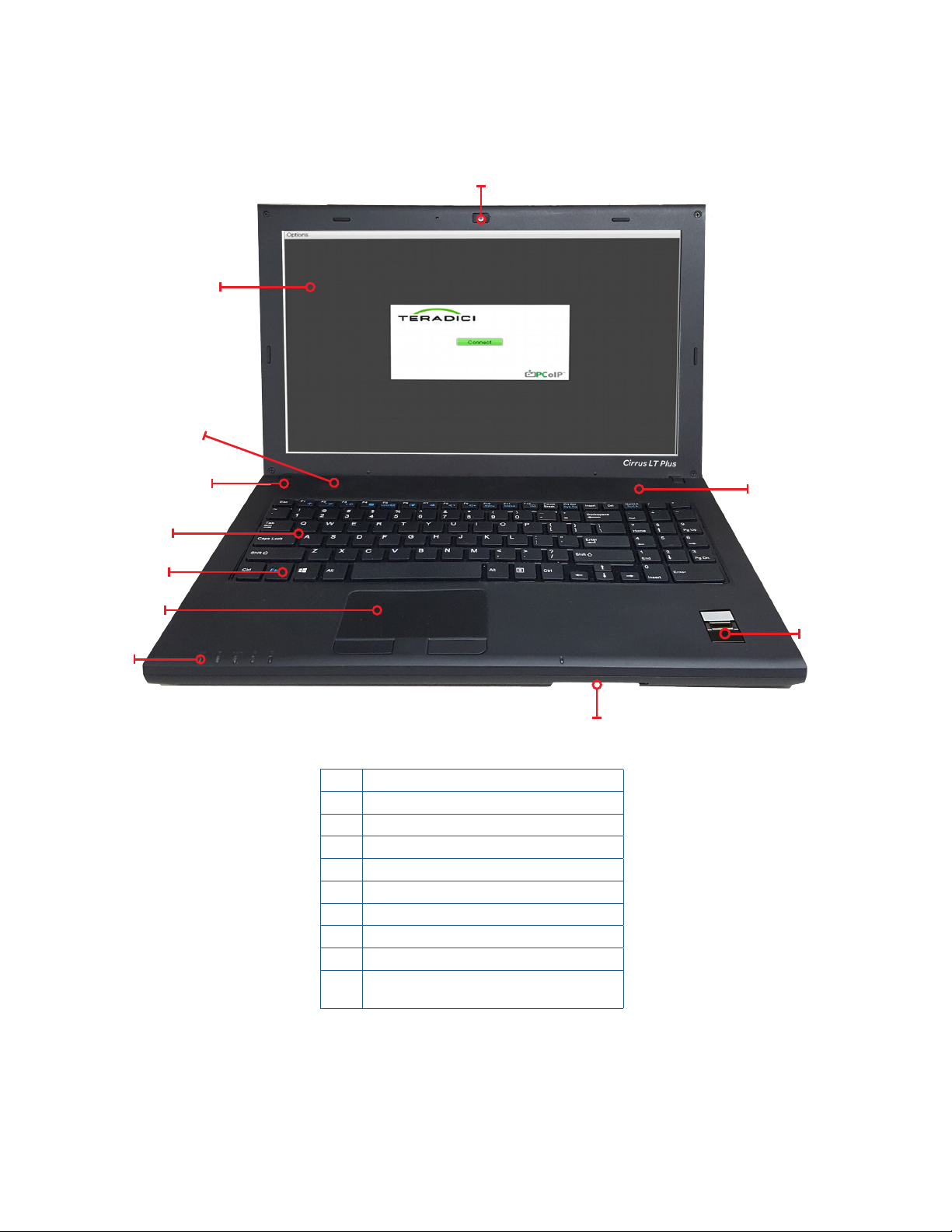
Components
2
3
1
4
5
6
7
8
10
1 Optional built-in PC webcam
2 LCD screen
3 Speakers
4 Power button/LED
5 Keyboard
6 Function (Fn) key
7 Touchpad & buttons
8 LED indicators
9 Optional fingerprint reader
10 Smart card reader (CAC) or optional
internal proximity card reader
3
9
10 Cirrus LT Plus User Manual v1.2 - Chapter 1
Page 11
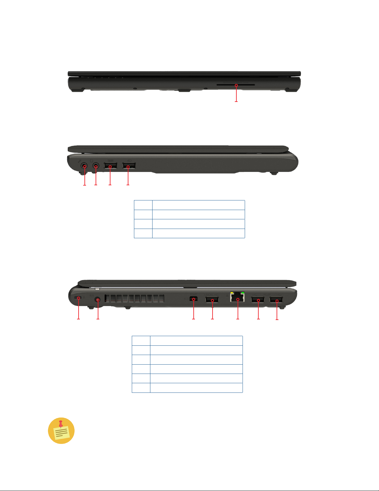
Front view
Right View
Smart card reader
2
1
Left view
1
2
4
3
1 Microphone jack
2 Headphnes/headset jack
3 Dedicated keyboard USB port
4 Dedicated mouse USB port
3
4
1 Security key lock
2 DC-in jack
3 Mini DisplayPort
4 Charging USB port*
5 RJ-45 LAN jack
6 PCoIP USB ports
5
6
6
*This port is labeled “Local” on the notebook, but it functions as a USB
charging port for certain devices. Devices plugged into this port will not be
seen in the remote session.
Cirrus LT Plus User Manual v1.2 - Chapter 1
11
Page 12
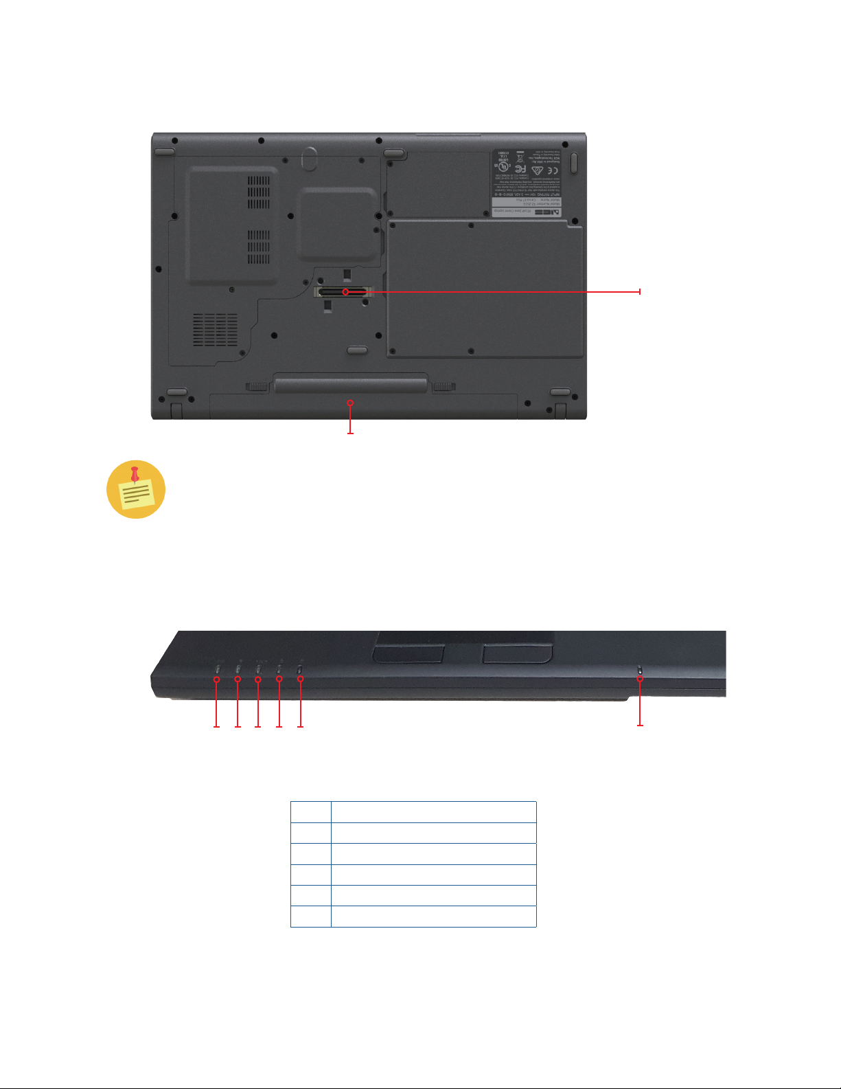
Bottom view
The docking station port may be covered with a rubber cover to keep dust
and debris out of the connector when not in the dock
Docking
station
connector
Battery
Notebook LEDs
1
2
4
3
5
1 Battery
2 WiFi
3 PCoIP
4 Caps Lock
5 Num Lock
6 Proximity card
6
12 Cirrus LT Plus User Manual v1.2 - Chapter 1
Page 13
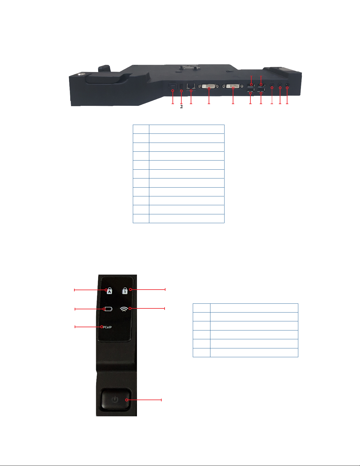
Docking station rear view
1 Fiber SFP port
2 Charging USB port
3 RJ-45 LAN jack
4 DVI-1 port
5 DVI-2 port
6 PCoIP USB 2.0 ports
7 Dedicated mouse USB port
8 Dedicated keyboard USB port
9 Speaker/line out
10 Microphone
11 DC-in jack
7
6
3 4
2
1
5 6 8 9 10 11
Docking station LEDs
1
2
3
4
5
6
1 CapsLock
2 Battery
3 PCoIP Session Status
4 NumLock
5 WiFi Status LED
6 Power/Connect Button
Cirrus LT Plus User Manual v1.2 - Chapter 1
13
Page 14

Laptop and docking station LED status light indicators
Green LED – Normal Operation – unit is powered on
Amber LED – Wake On LAN is enabled/unit is OFF
Power LED
Battery LED
Wireless LED
PCoIP LED
Caps Lock LED
NumLock LED
No LED – unit is off (Wake on LAN is disabled)
Blinking Green LED – Host PC is in low power (sleep state)
Blinking Green and Amber - unit is in the process of upgrading BIOS (DO NOT
TURN OFF)
Green LED – Battery is full or AC adapter is plugged IN
Blinking Green LED – Battery is charging
Blinking Amber LED - Low Battery, Battery is under 10% charge, or battery is
not present
Amber LED – charging error
NO LED – normal operation, battery discharging
Green LED – Wireless is enabled/ this can be on when not connected to a
wireless LAN.
NO LED – Wireless is disabled
Green LED – Connected to a remote host
NO LED – no connection present
Green LED – CAPS LOCK Enabled
NO LED – CAPS LOCK Disabled
Green LED – NumLock Enabled
NO LED – NumLock Disabled
14 Cirrus LT Plus User Manual v1.2 - Chapter 1
Page 15

Chapter 2: Getting started
This chapter will guide you on how to use your notebook.
It covers the following sections:
• Powering up your notebook
• Battery installation
• Installing/uninstalling a SIM card
• Opening the display panel
• Starting your notebook
• Using the keyboard
• Using the touchpad
• Navigating the OnScreen Menu (OSM)
Powering up your notebook
Your notebook can be powered up using the AC adapter, a removable lithium-ion
battery, or an optional factory installed dual battery configuration.
Connecting the AC adapter
The AC adapter powers up your notebook and charges the battery.
• Connect the AC adapter to the DC-in jack of your notebook.
• Connect the AC adapter to the power cord.
• Plug the power cord to an electrical outlet.
Cirrus LT Plus User Manual v1.2 - Chapter 2
15
Page 16
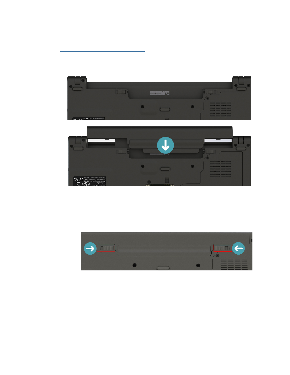
Removable battery installation
Installing the removable battery
To install the battery, follow the steps below:
1. Align and slide the battery into the battery compartment.
2. Push the battery into the compartment until the battery locks into place,
and make sure the latches are locked into position. The left latch will
automatically go into the locked position when you push the battery in
place, but you must manually lock the right latch, as shown.
16 Cirrus LT Plus User Manual v1.2 - Chapter 2
Page 17

Charging the removable battery
The removable lithium-ion battery is not fully charged upon purchase. To
charge the battery, follow the steps below:
1. Install the battery to your notebook. See procedure above.
2. Connect the AC adapter to the DC-in jack of your notebook.
3. Connect the AC adapter to the power cord.
4. Plug the power cord into an electrical outlet.
Charging the removable battery while the Cirrus LT Plus is powered off will
shorten the charging time to two hours. If the Cirrus LT Plus is on, it will take
approximately eight hours to charge the unit.
Using battery power
Install the charged battery in the battery compartment by removing the AC
adapter (if plugged in). Your notebook will automatically use the battery power.
Recalibrating the battery
If you notice your removable battery pack is not lasting as long over time, you
may need to recalibrate it. Over time, the 100% charge level can get skewed so
it may only charge to actually 85% or lower. You can fix this by removing the
battery from the notebook, then putting it back in. This will reset its circuitry to
start relearning where the 100% charge level is again.
Cirrus LT Plus User Manual v1.2 - Chapter 2
17
Page 18

Optional dual battery support
Your Cirrus LT Plus may be equipped with a secondary internal Lithium Polymer battery. This is a factory installed option and isn’t intended to be serviced or
removed by the customer.
Install the removable battery as indicated above.
Charging both the removable and internal batteries while the Cirrus LT Plus is
powered off will shorten the charging time to two hours. If the Cirrus LT Plus is
on, it will take approximately five hours to charge the unit.
If your Cirrus LT Plus is equipped with dual batteries, the external battery can
be changed without powering down, since the internal battery keeps the laptop
running.
18 Cirrus LT Plus User Manual v1.2 - Chapter 2
Page 19
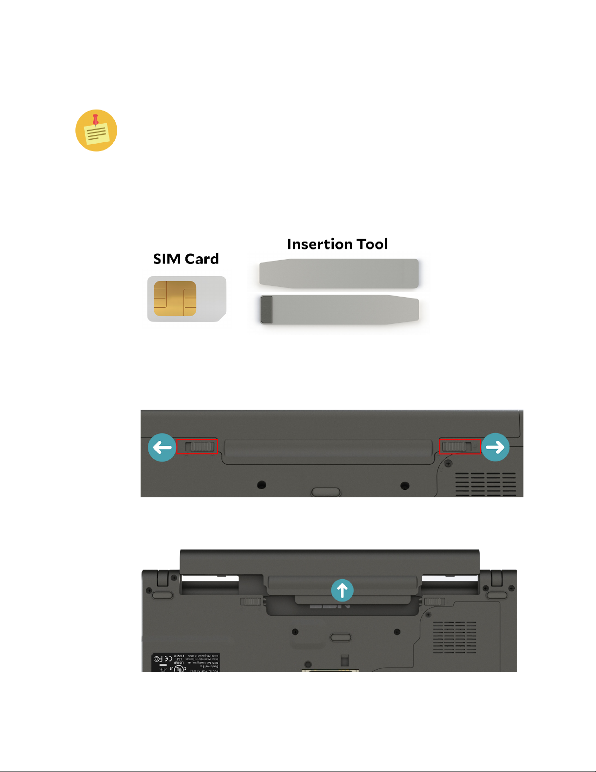
Installing/Removing the SIM card
For instructions on how to configure 4G functionality via the OnScreen
Menu, refer to Chapter 4.
Installing the SIM card
To install the SIM card into your Cirrus LT Plus, follow the steps below:
1. Make sure you have your SIM card and the insertion tool included with your
Cirrus LT Plus on hand.
2. Remove the Cirrus LT Plus’ external battery from the notebook bottom by
sliding the tabs to the unlocked position.
3. Remove the battery.
Cirrus LT Plus User Manual v1.2 - Chapter 2
19
Page 20
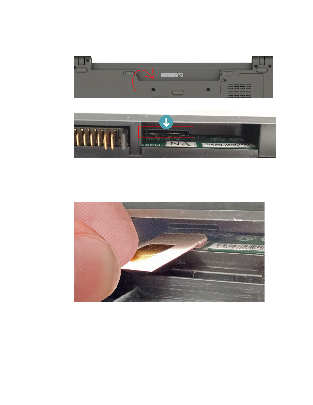
4. Locate the SIM card slot located inside the notebook battery compartment, as
highlighted below.
5. Using your fingers, carefully line the SIM card (with the chip side facing up
and the clipped corner facing away from you with the slot.
20 Cirrus LT Plus User Manual v1.2 - Chapter 2
Page 21
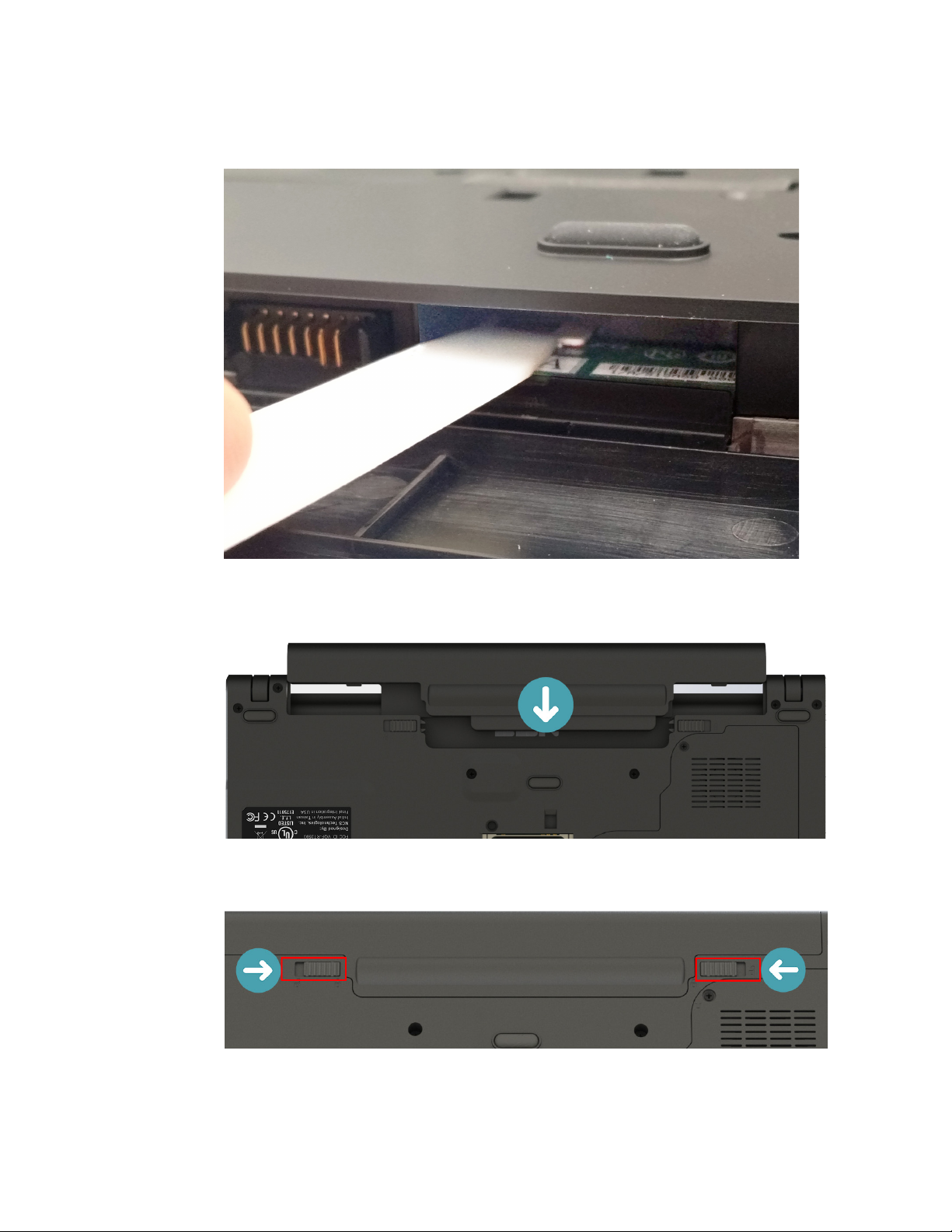
6. Use the insertion tool to gently push the SIM card into the slot until you hear
it click into place.
7. Reinstall the external battery.
8. Slide tabs to locked position.
Cirrus LT Plus User Manual v1.2 - Chapter 2
21
Page 22
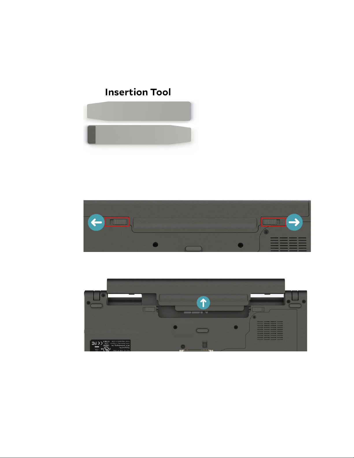
Removing the SIM card
To remove your SIM card from the Cirrus LT Plus, follow the steps below:
1. Make sure you have the insertion tool included with your Cirrus LT Plus
packaging.
2. Remove the Cirrus LT Plus’ external battery from the notebook bottom by
sliding the tabs to the unlocked position.
3. Remove the battery.
22 Cirrus LT Plus User Manual v1.2 - Chapter 2
Page 23
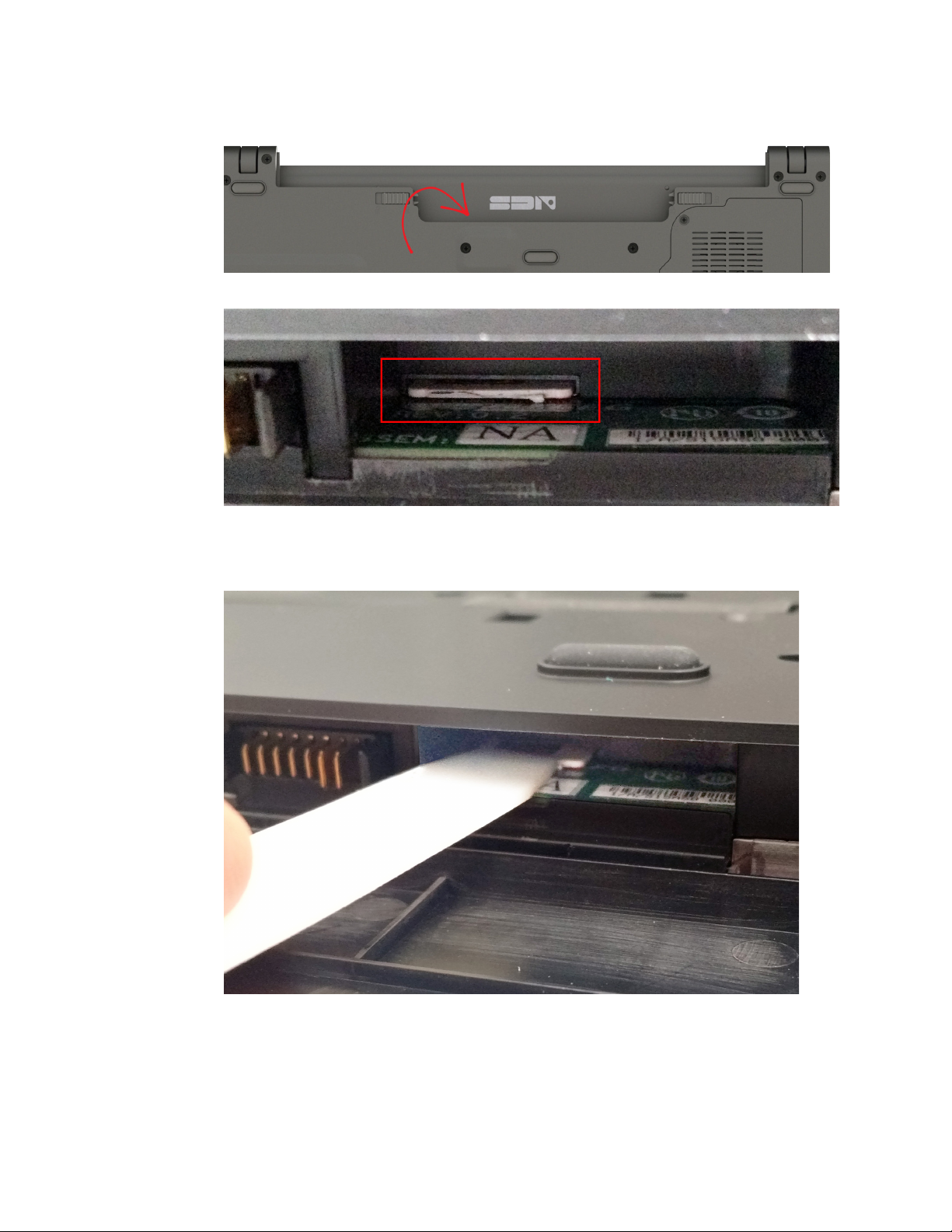
4. Find the SIM card slot located inside the notebook battery compartment.
5. Use the included removal tool to push-to-eject the SIM card.
Cirrus LT Plus User Manual v1.2 - Chapter 2
23
Page 24
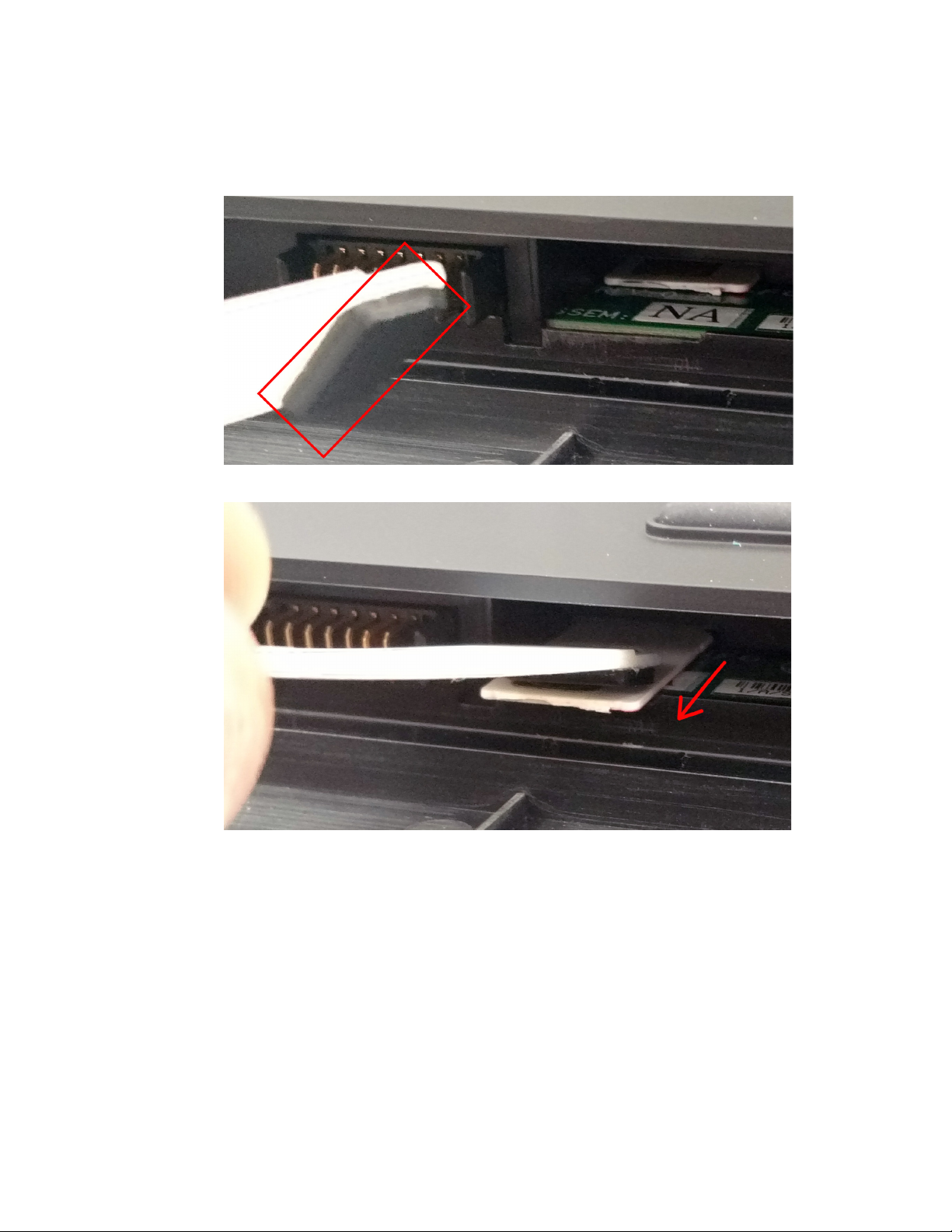
6. Now use the opposite end of included removal tool (with the black rubber pad
tip, as shown below) to grip the SIM card and fully remove it from its enclosure.
24 Cirrus LT Plus User Manual v1.2 - Chapter 2
Page 25
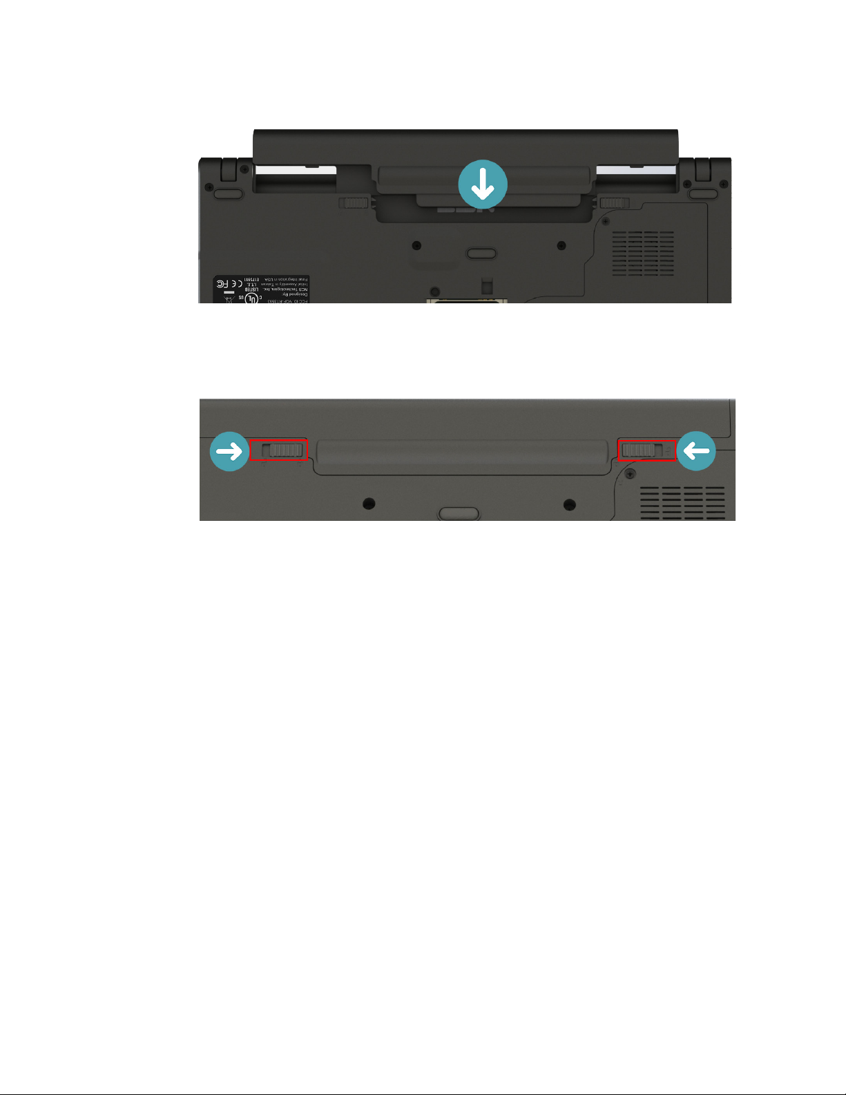
7. Reinstall the external battery.
8. Slide tabs to locked position.
Cirrus LT Plus User Manual v1.2 - Chapter 2
25
Page 26
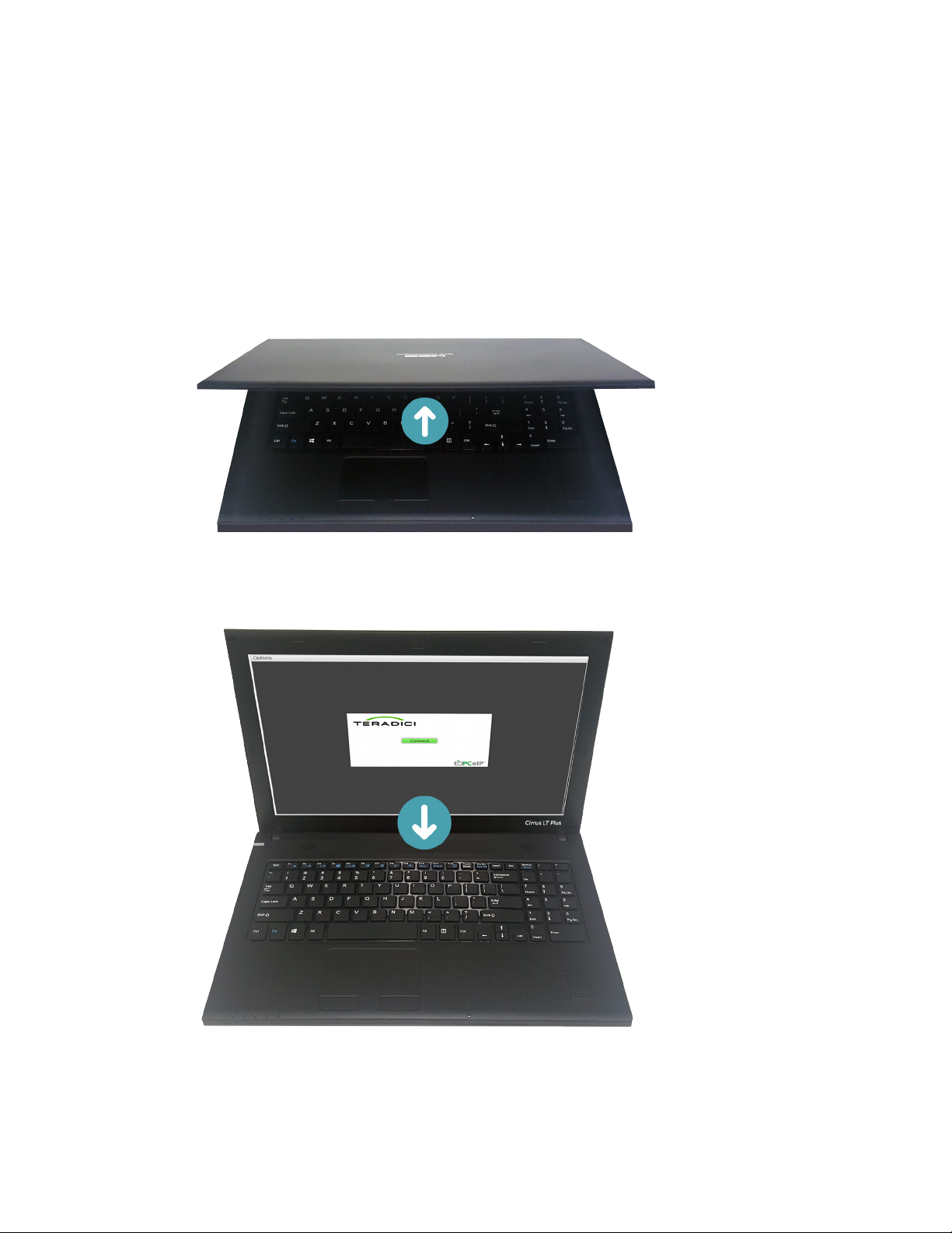
Starting your notebook
Opening the display panel
The notebook lid is secured with small magnets while closed and is easily
opened.
• To open, simply lift the cover lid up to the upright position.
• To close, carefully place the cover lid down. Do not slam it shut.
26 Cirrus LT Plus User Manual v1.2 - Chapter 2
Page 27
Turning on your notebook
• Press the Power button until the Power LED lights up.
To force a hard shut down, press and hold the Power button for more than
four seconds.
Using the keyboard
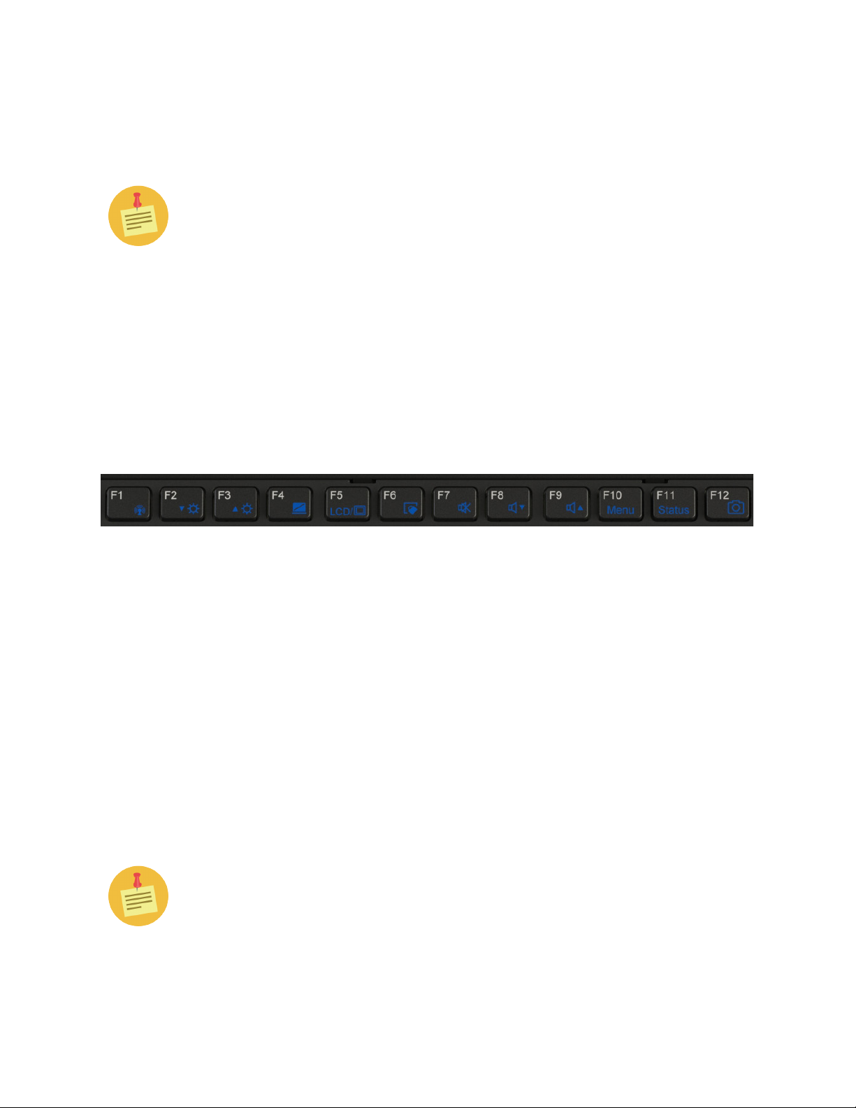
Function keys
The function keys allow you perform certain tasks on your notebook. Below is a
list of the function keys and their actions:
Fn-F1: Turns WiFi on and off
Fn-F2: Decreases screen brightness
Fn-F3: Increases screen brightness
Fn-F4: Turns Native Display on and off
Fn-F5: Toggles between various available display modes
Fn-F6: Enables and disables the touchpad
Fn-F7: Turns sound on and off
Fn-F8: Decreases volume
Fn-F9: Increases volume
Fn-F10: Brings up OnScreen Menu (OSM)
Fn-F11: Turns status bar on and off
Fn-F12: Enables or disables webcam (webcam optional)
Wherever Fn-F10 is used from here on out in the document you can also use
SHIFT-F10 when using an external USB keyboard.
Cirrus LT Plus User Manual v1.2 - Chapter 2
27
Page 28

Touchpad
The touchpad is a cursor-pointing device. You can point, select, or drag items or objects on the screen. For more details on configuring the touchpad, see Device Man-
ager Section in Chapter 4.
Point
Slide your finger on the touchpad to point the cursor to an item or object on the
screen.
Click
To left-click, move the cursor to the item or object on the screen, then lightly tap
the touchpad or press the left button (by default this tapping feature is disabled
in NCS Firmware to prevent unwanted cursor movements while typing. Refer
to Chapter 4’s Device Manager section to enable this feature.).
To right-click, move the cursor to the item or object on the screen, then press
the right button.
Double-click
To double-click, move the cursor to the item or object on the screen, then tap
the touchpad twice or press the left button twice (by default this tapping feature
is disabled in NCS Firmware to prevent unwanted cursor movements while typing. Refer to Chapter 4’s Device Manager section to enable this feature.).
Drag
To drag an item or object, press and hold the left button then slide your finger on
the touchpad to move the item or object.
The Cirrus LT Plus does not support advanced touchpad features such as
scrolling, pinching, and multi-touch.
28 Cirrus LT Plus User Manual v1.2 - Chapter 2
Page 29
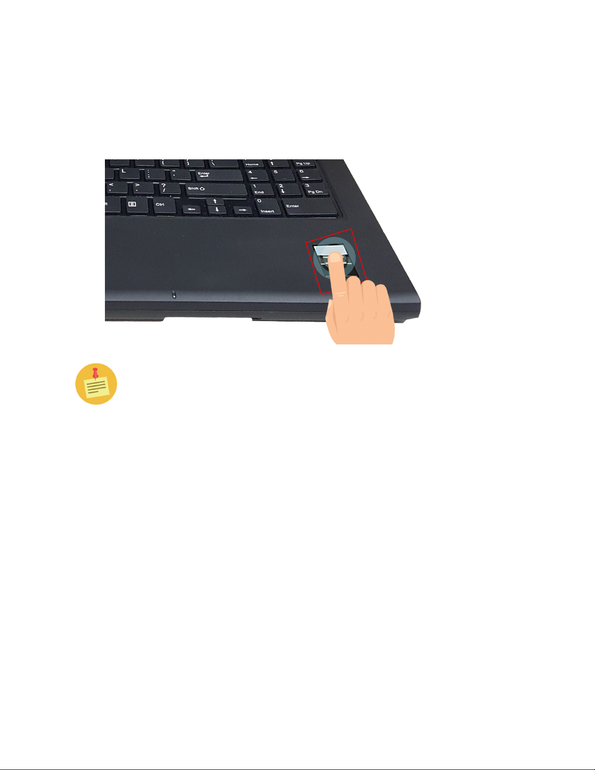
Using the fingerprint reader
Shown below is the optional scanning fingerprint reader. There is also an option for
a swipe fingerprint reader or for no fingerprint reader at all.
You will need to load your appropriate drivers on your virtual machine or
remote host to support this device. Drivers can be downloaded from our
NCS website at http://www.ncst.com/content/downloads-0
Cirrus LT Plus User Manual v1.2 - Chapter 2
29
Page 30

Chapter 3: Making connections
This chapter will guide you on installing peripheral devices to maximize the use of your
notebook. It covers the following sections:
• Connecting External Display Devices
• Connecting USB Devices
• Connecting Headphones
• Connecting External Microphone
Connecting external display devices
You can connect your notebook to other display devices, such as a projector or another display monitor.
Your notebook is equipped with a mini DisplayPort which provides digital video
signals.
The DisplayPort cable is not included in the package. It is sold separately or
it may come with your external display device.
The Cirrus LT Plus is designed to support both passive and active mini DP
to DVI adapters. The Cirrus LT Plus is compatible with most new adapters
but there are a few older adapters that will not work. NCS sells a variety of
adapters for most modern LCDs out in the market today, i.e. Mini DP to DP,
Mini DP to DVI, Mini DP to VGA, etc. You may purchase these mini DP
adapters from NCS to ensure complete compatibility for your Cirrus LT
Plus. Additionally, due to the nature of converting mini DP to VGA, all of
these adapters are considered active adapters.
Connecting a projector or display monitor
30 Cirrus LT Plus User Manual v1.2 - Chapter 3
Page 31
1. Connect one end of a DisplayPort cable to the mini DisplayPort of your
notebook.
2. Connect the other end to a projector or display monitor.
Connecting USB devices
You can connect your notebook to other USB devices, such as a mouse, keyboard,
digital camera, printer, or an external hard disk drive. Connect one end of a USB cable to the USB port of your notebook, then connect the other end to the USB device.
The USB cable is not included in the package. It is sold separately or it may
come with your USB device.
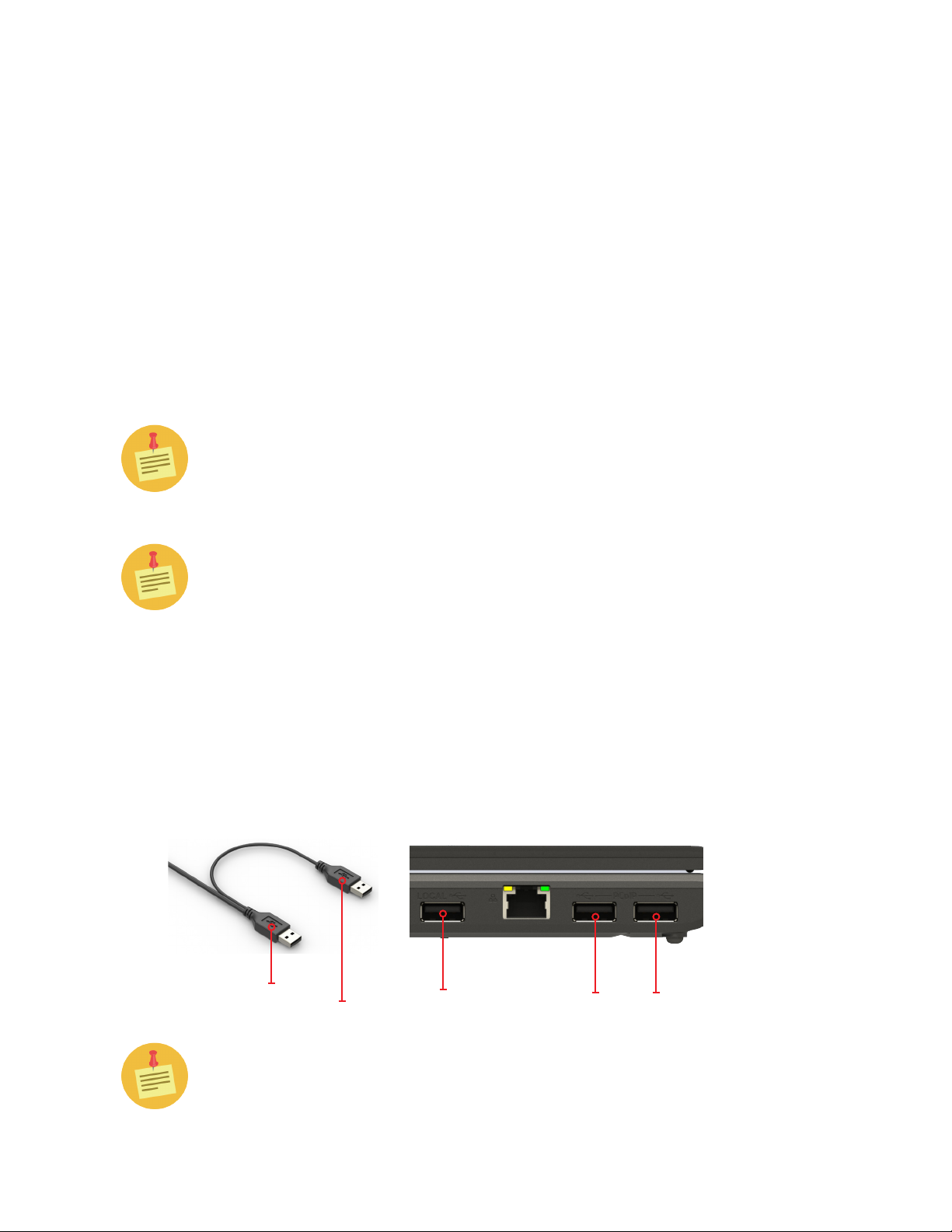
USB devices (including, but not limited to, printers, optical drives, and hard
drives) that do not have their own power sources are not officially supported. Most of these devices tend to draw too much power from the USB port.
You can still connect these devices to the Cirrus LT Plus. If the device only
has one USB port, use one of the two PCoIP USB ports on the left side of the
notebook. If the device has two USB ports (one for enumeration and one for
auxiliary power), use one PCoIP USB port for the enumeration plug and the
charging USB port (also located on the left side of the notebook) for the
auxiliary power plug. Refer to the image below. As a reminder, these USB
devices that are plugged in may need drivers to be loaded on the remote
session.
Enumeration
Plug
Auxiliary
Plug
Charging
USB Port
The aforementioned ports are located on the left side of the notebook.
Cirrus LT Plus User Manual v1.2 - Chapter 3
PCoIP USB Ports
31
Page 32

Connecting to a mouse and keyboard
Using a mouse in the dedicated mouse port ensures full functionality when connected to a remote host and when you pull up the OnScreen Menu. The same applies for the dedicated keyboard port.
To connect to an external mouse:
• Plug the mouse into the USB port with the picture of a mouse over it.
To connect to an external keyboard:
• Plug the keyboard into the USB port with the picture of the keyboard over it.
The mouse and keyboard are not included in the package. They are sold
separately.
When using an external keyboard in the dedicated USB keyboard port you
can press SHIFT-F10 to bring up the Cirrus LT Plus OnScreen Menu.
Certain special multifunction or Bluetooth combo mouse and keyboards will work
in the dedicated keyboard port. Not all of these special devices have been tested. As
a general rule, you can try different keyboards without harming the Cirrus LT Plus.
Special keyboards should be plugged into the dedicated USB keyboard port on the
right hand side for compatibility. Combo Bluetooth keyboard and mouse dongles
should be plugged into the dedicated USB keyboard port.
If for some reason these special keyboards do not work in the dedicated keyboard
port, try them on the PCoIP USB ports on the left hand side of the notebook. You
may need to load drivers once the device is detected in the remote OS. Please contact NCS Help Desk if you identify a USB keyboard that does not work correctly
in the dedicated USB keyboard port. We are always looking to make our products
compatible with the latest peripherals.
32 Cirrus LT Plus User Manual v1.2 - Chapter 3
Page 33
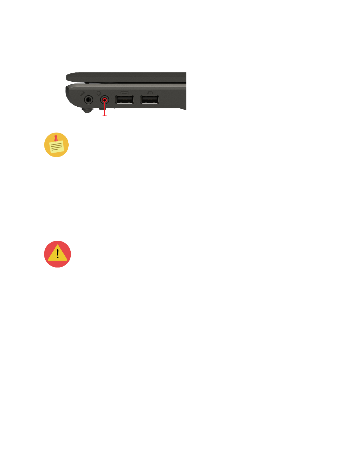
Connecting headphones
Headphones/headset port
The headphones/headset port is located on the right side of the notebook.
You can connect either headphones or external speakers to the Cirrus LT Plus
Notebook via its headphones/headset port (see above). This headphone/headset
port also supports combo headsets (headphone/mic) which come with a single plug
(seen, for example on the iPhone® headphone), as well as CTIA and OMTP Headsets.
Headsets are not compatible with the headphone port on the docking
station or with the microphone jacks on the notebook or the docking station.
Audio subsystem
By default, audio will be output to the Cirrus LT Plus’ built-in speakers when
the headphones/headset port is not used. If a webcam is installed, the webcam
microphone can be used for applications like Skype.
When a headset (e.g. an Apple® headset) is plugged in, audio will be output to
this headset. Also, the headset microphone will get priority if a dedicated microphone is also connected to the Cirrus LT Plus microphone jack.
Cirrus LT Plus User Manual v1.2 - Chapter 3
33
Page 34

Connecting an external microphone
You can connect your notebook to an external microphone by plugging the audio
jack of the microphone to the microphone jack of your notebook.
If you want to use the docking station microphone jack while on a virtual
machine, you must install a driver. You can download this driver at http://
www.ncst.com/content/downloads-0
If you have a USB headphone and microphone device, plug these into the
PCoIP USB ports.
34 Cirrus LT Plus User Manual v1.2 - Chapter 3
Page 35
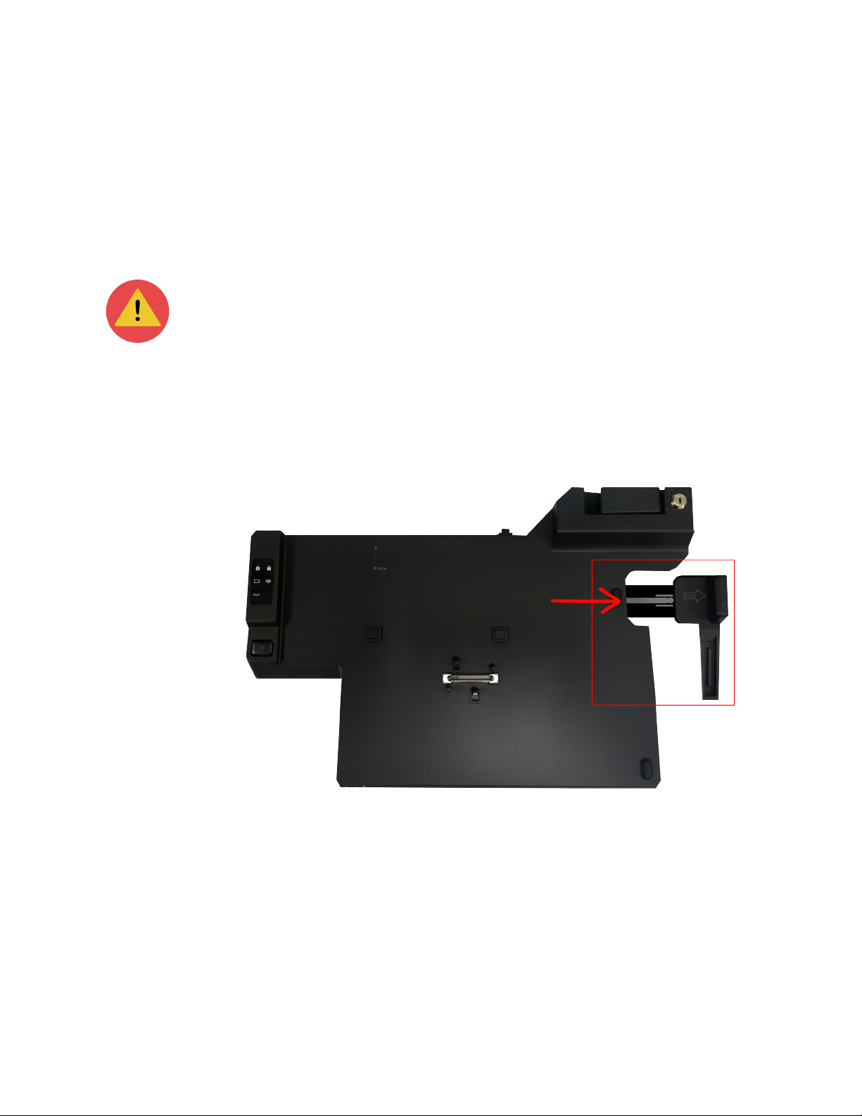
Connecting to the docking station
You can connect your notebook to a docking station. The docking station has many
of the same ports as the notebook, but also features two DVI-D ports and a Fiber
SFP port.
The notebook and docking station use different AC adapters. You must
connect the 90 Watt AC Adapter (19V, 4.74A) to the docking station in order
for the Cirrus LT Plus to function correctly while in the docking station.
Connecting the docking station
To connect your notebook to the docking station:
1. Pull out the extender on the right side of the docking station.
Cirrus LT Plus User Manual v1.2 - Chapter 3
35
Page 36
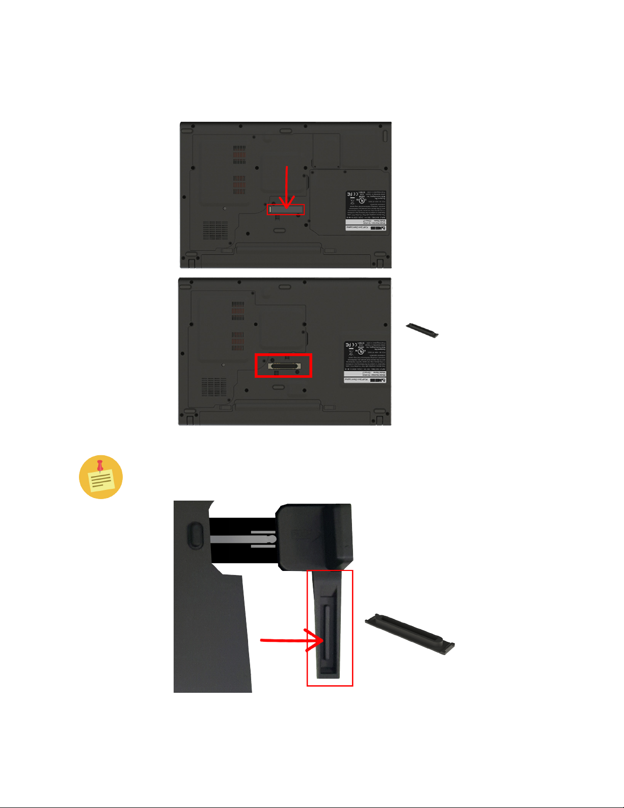
2. Ensure the notebook docking station port cover (highlighted below) is
removed before you try to dock the notebook onto the docking station.
There is also a handy storage location for this port cover located on the
docking station lever. See the highlighted area shown below.
36 Cirrus LT Plus User Manual v1.2 - Chapter 3
Page 37
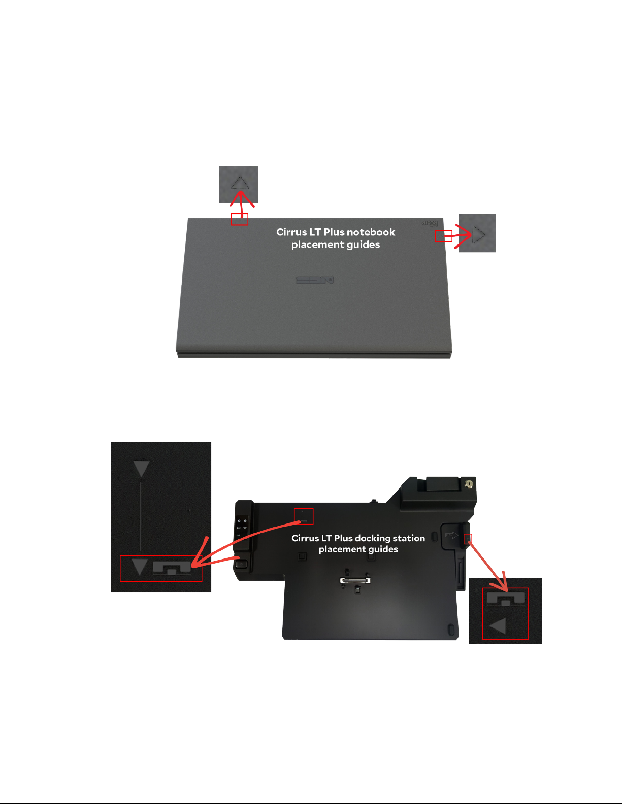
3. Note the following highlighted guides below on both the notebook and
the docking station for correct placement when connecting the notebook
to the docking station.
• There are two small triangle guides on the notebook lid.
• There are also two guides on the docking station.
Cirrus LT Plus User Manual v1.2 - Chapter 3
37
Page 38
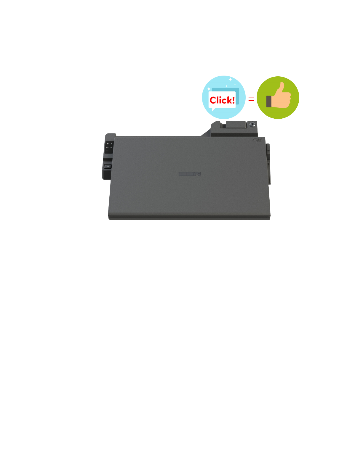
4. Line these up, and then firmly press down on the lid of the notebook. You
should hear a click, and then the notebook is properly docked into the
docking station.
38 Cirrus LT Plus User Manual v1.2 - Chapter 3
Page 39
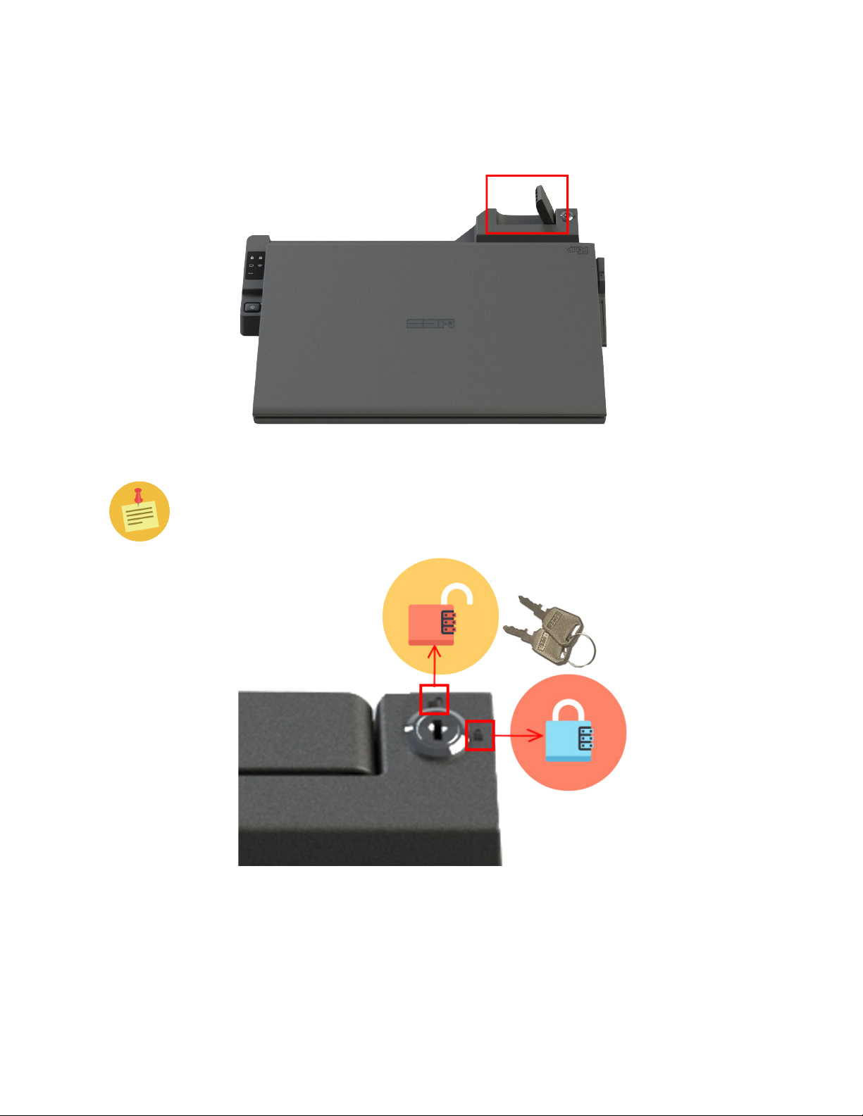
Disconnecting from the docking station
To disconnect your notebook from the docking station:
1. Pull up the black lever on the top right side of the docking station.
If the black lever won’t lift up, you will need to unlock the docking station
with the included keys (shown below) to remove the notebook. The release
lever will not lift up if locked.
2. Lift the notebook out of the docking station.
Cirrus LT Plus User Manual v1.2 - Chapter 3
39
Page 40
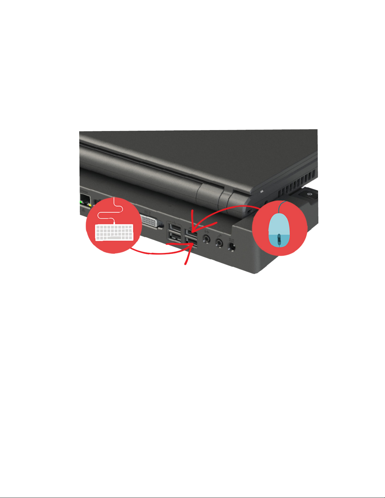
USB port functionality while notebook is docked
While the Cirrus LT Plus is docked with the docking station, the notebook’s
dedicated USB keyboard and mouse ports will not work; only the corresponding ports of the docking station remain active (highlighted below) while docked.
These ports are labeled with an icon of a mouse and a keyboard. However, the
two PCoIP and charging ports on the notebook will still work giving you a total
of 6 working USB Ports when using the docking station and two charging USB
ports.
Hotdocking
Hot-docking (placing the Cirrus LT Plus on the docking station while the Cirrus
LT Plus has power) is now fully supported.
40 Cirrus LT Plus User Manual v1.2 - Chapter 3
Page 41
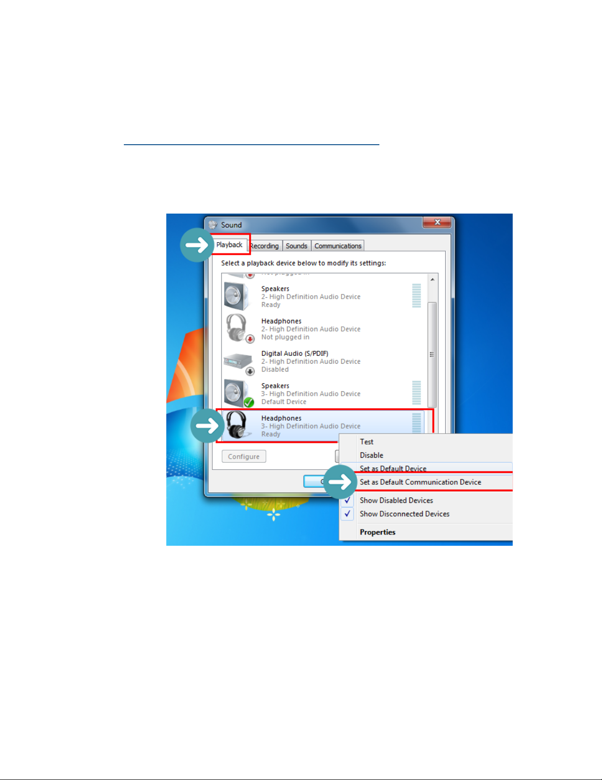
Configuring the audio for remote hosts
Connecting to the Teradici host PC
Headset port or built-in speaker configuration:
1. Open the Control Panel > Sound > Playback tab.
2. In the Playback tab, select Headphones: 3-High Definition Audio Device
as the Default Communication Device.
Cirrus LT Plus User Manual v1.2 - Chapter 3
41
Page 42
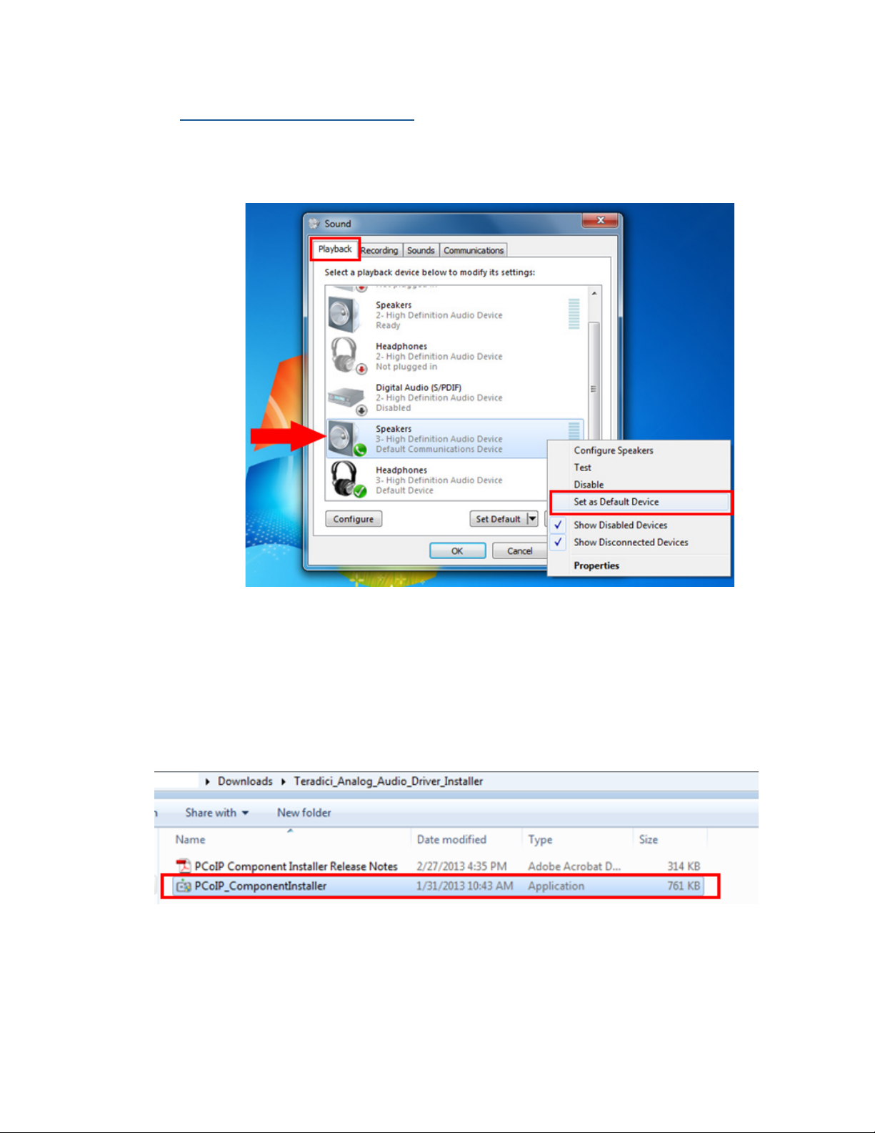
Docking station line out port:
1. Open the Control Panel > Sound > Playback tab.
2. In the Playback tab, select Headphones: 3-High Definition Audio Device
as the Default Device.
Connecting to VMHost
1. Download and install the latest PCoIP Audio Driver provided by Teradici
(PCoIP_ComponentInstaller.exe).
42 Cirrus LT Plus User Manual v1.2 - Chapter 3
Page 43
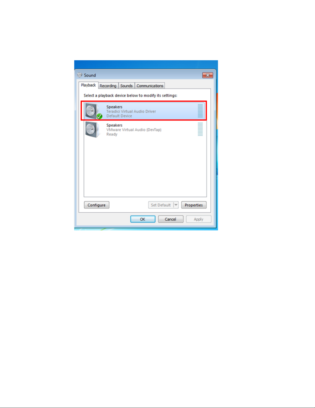
2. Open the Control Panel > Sound > Playback tab.
3. Ensure that the Teradici Virtual Audio Driver is selected as the default driver.
The Speakers setting will work for both the Headset Port and Dock Line-out
Port.
Cirrus LT Plus User Manual v1.2 - Chapter 3
43
Page 44
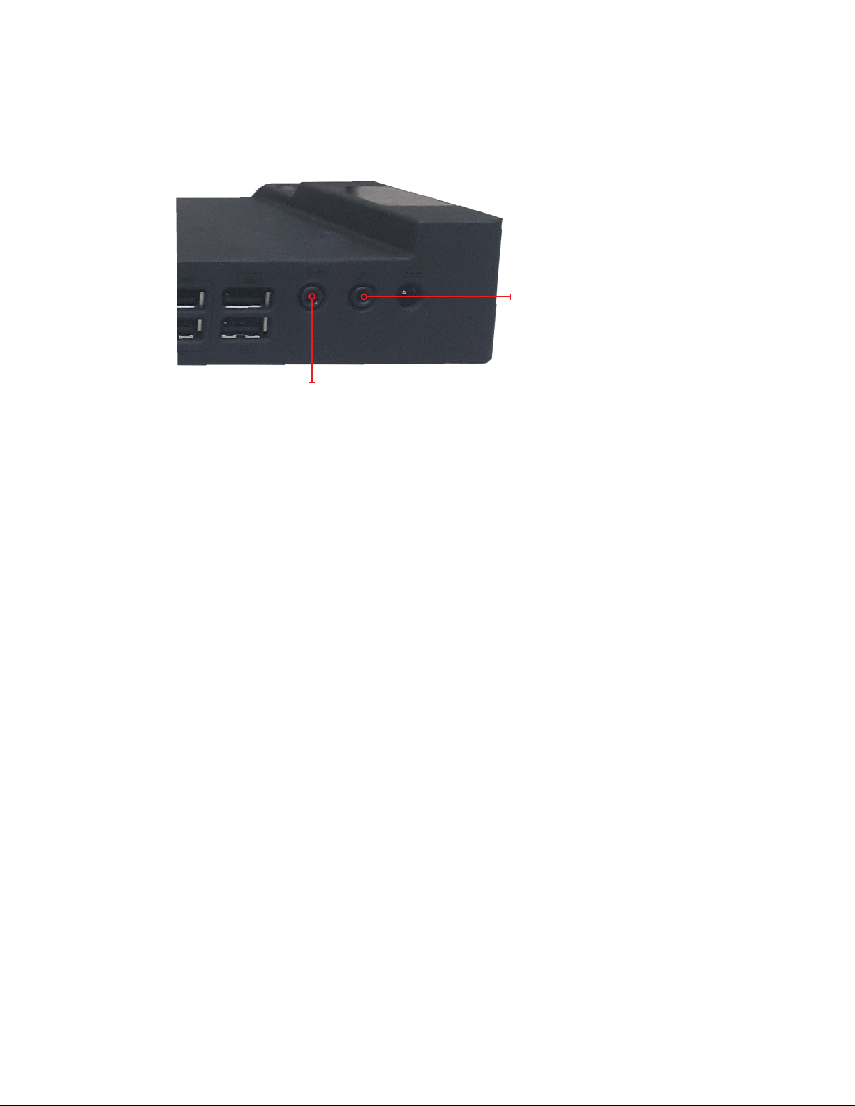
Docking station audio subsystem
The Cirrus LT Plus docking station has a line-out port (located on the rear right
side) which is intended to be connected to desktop speakers (see below).
Microphone jack
Speaker jack
The docking station microphone jack is a replica of Cirrus LT Plus microphone
jack to support traditional analog microphones only.
Priority of the audio plugs while docked are as follows:
• By default, audio will be output to the built-in speakers when Headset/Line-out
port is not used. If a webcam is installed, the webcam mic can be used for applications like Skype.
• When the line-out port on the docking station is connected to an external speaker, this port will get priority and internal speakers will not produce sound. Similarly, docking station microphone port will get priority when used over the ports
on the Cirrus LT Plus.
• When the docking station ports are not used, the Cirrus LT Plus audio ports and
speakers will have priority.
44 Cirrus LT Plus User Manual v1.2 - Chapter 3
Page 45
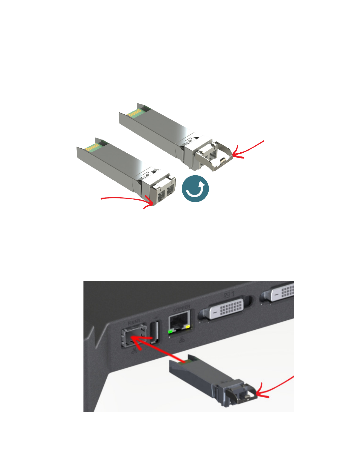
Installing a SFP module
The SFP module goes into the Fiber SFP port on the docking station and allows you
to use fiber optic cable for more secure networking. You will need to pull the tab
lever out prior to installation, as shown below.
To install the SFP module:
1. Place the SFP module into the Fiber SFP port (refer to Chapter 1, rear view
port #1 for exact location). Make sure the side with the green tab is facing up,
and the tab lever is pulled out, as shown below.
Cirrus LT Plus User Manual v1.2 - Chapter 3
45
Page 46
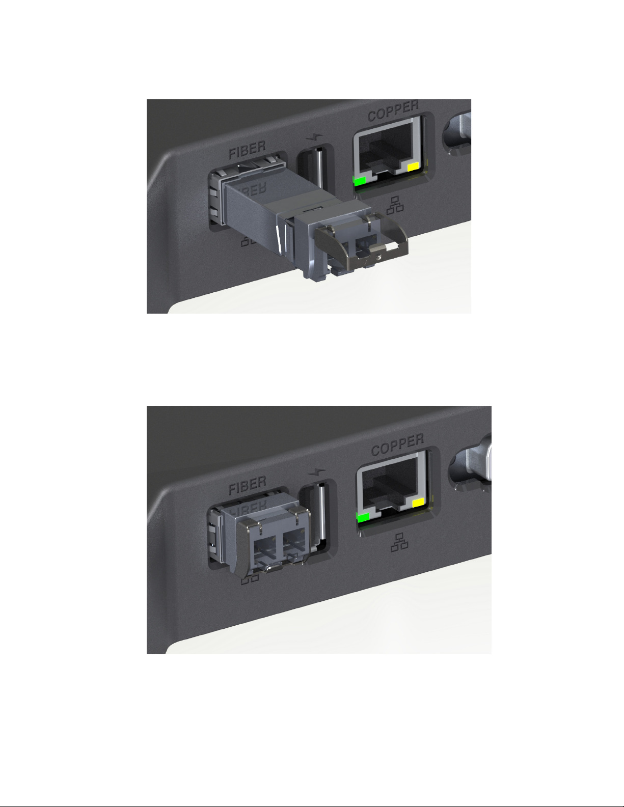
2. Push the module all the way into the port.
3. You will know the module is securely installed when you hear a click as you
push it into place. Pull the lever down back into place, as shown below.
46 Cirrus LT Plus User Manual v1.2 - Chapter 3
Page 47

Chapter 4: Navigating the OnScreen Menu
Use the OnScreen Menu (OSM) to configure various parameters on your Cirrus LT Plus.
To invoke the OSM you press Fn-F10. You can navigate through the OSM with the touchpad or with an external mouse connected to the dedicated USB Mouse Port located on the
right side of your notebook.
When using an external USB keyboard that is connected to the dedicated USB keyboard
port (on the right side of the notebook) you can also invoke the OSM by pressing SHIFTF10. This is handy when using the notebook with the lid closed. Since most external keyboards do not have a function key, pressing SHIFT-F10 will bring up the OSM for your
convenience.
OnScreen Menu (OSM) structure
The OnScreen Menu (OSM) is based on a tree structure moving from left to right
as you drill deeper into the menu system. Each level of the tree will have a title and
various options to choose from; either click an option to move down the tree or to
make a selection with the mouse pointer. You can also click any option higher in the
tree structure to select that menu. Finally, to exit the OSM either click the X on the
bottom left corner of the menu or press Fn-F10 again.
When you open the OSM, a second cursor will appear. This cursor operates
within the OSM only. When you close the OSM, the cursor will disappear.
As you are clicking through the settings in the OSM, you will not have to
“confirm” any changes except in critical situations such as shutting down
the notebook or changing your password. All other changes will save automatically.
Cirrus LT Plus User Manual v1.2 - Chapter 4
47
Page 48
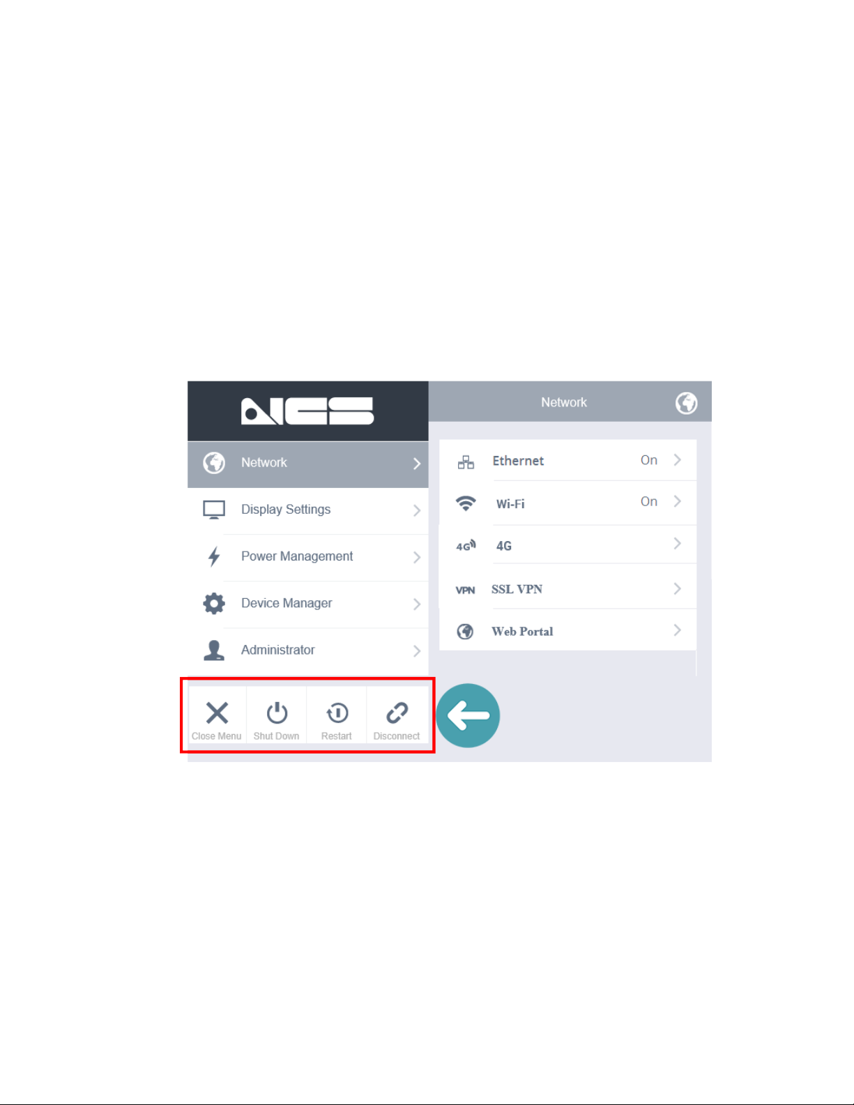
Main Menu
The main menu has the following items:
• Network: For changing network connectivity settings
• Display: For changing the display options and modes
• Power Management: For configuring OSM, Low Power Mode, and Sleep Timing
Preferences
• Device Manager: For configuring speaker volume, webcam, and touchpad
settings
• Administrator: For configuring authentication credentials of local and
administrator accounts and other administrator settings
The bottom left of the main menu (highlighted above) also allows you to close
the menu, shut down the system, restart the system, and connect/disconnect
from the remote session.
48 Cirrus LT Plus User Manual v1.2 - Chapter 4
Page 49
Network
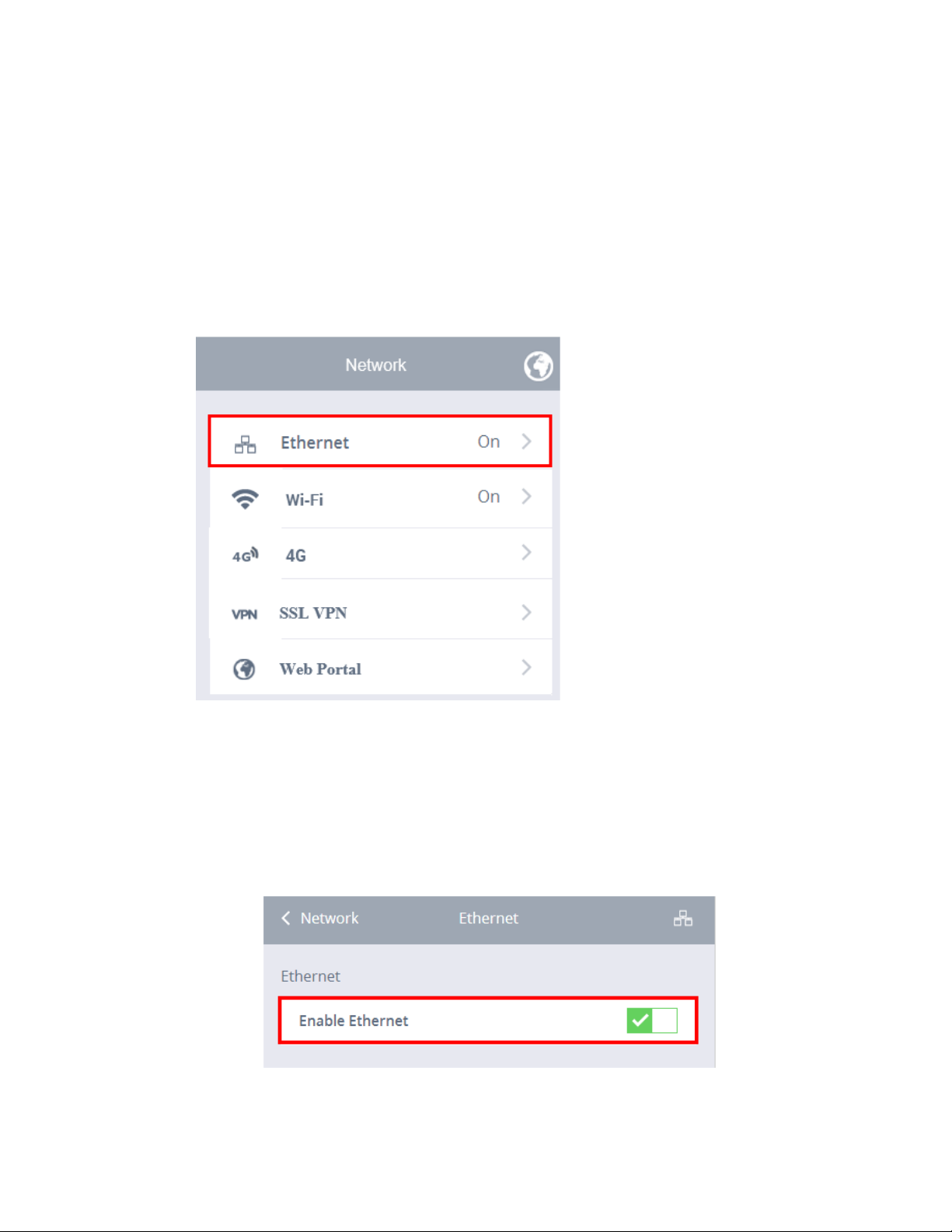
This network submenu lets you configure wired and wireless settings and allows
you to enable and disable both Ethernet and WiFi connections.
Ethernet
To enable the Ethernet:
1. Click the Network submenu.
2. Select Ethernet.
3. Click the Enable Ethernet selection box. A green check mark signifies that
Ethernet has been enabled, as shown below.
Cirrus LT Plus User Manual v1.2 - Chapter 4
49
Page 50
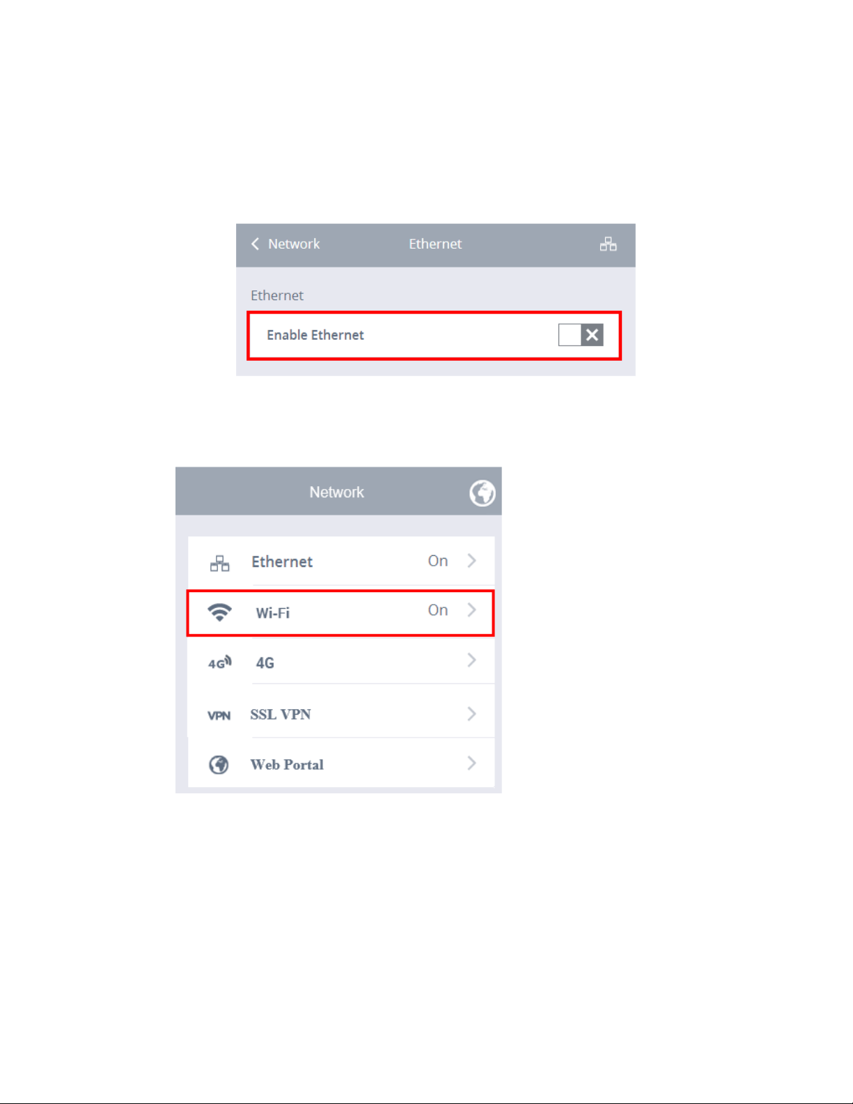
To disable the Ethernet:
1. Click the Network submenu.
2. Select Ethernet.
3. Click the Enable Ethernet selection box. A gray “X” signifies that Ethernet
has been disabled.
WiFi
All wireless configuration is done in these menus. You can enable or disable
wireless entirely. If you want to auto connect to the same set of wireless LANs
(WLANs) you can save those for auto connection at a later time (this can also be
disabled in the Administrator menu). Once connected to a WLAN, you can see
signal strength and the IP Address obtained.
50 Cirrus LT Plus User Manual v1.2 - Chapter 4
Page 51
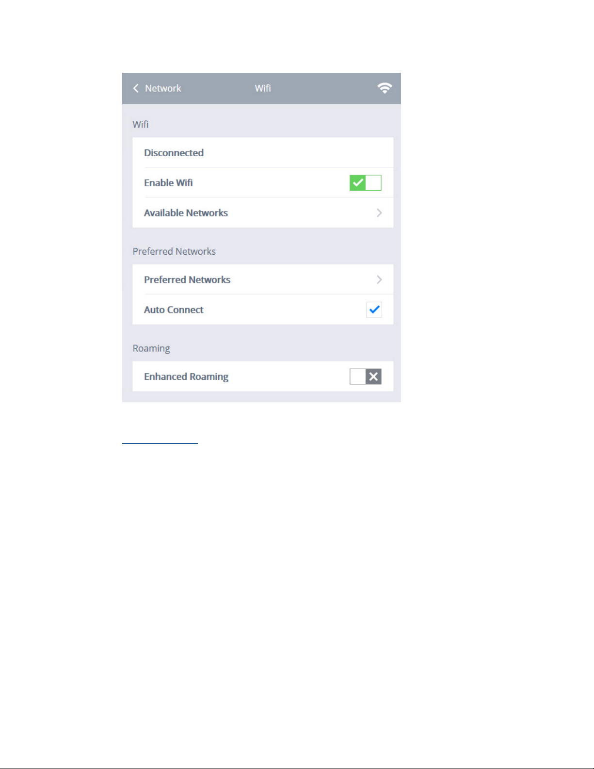
Disconnected
This tells you if WiFi is connected or disconnected.
Cirrus LT Plus User Manual v1.2 - Chapter 4
51
Page 52
Enabling and Disabling Wireless
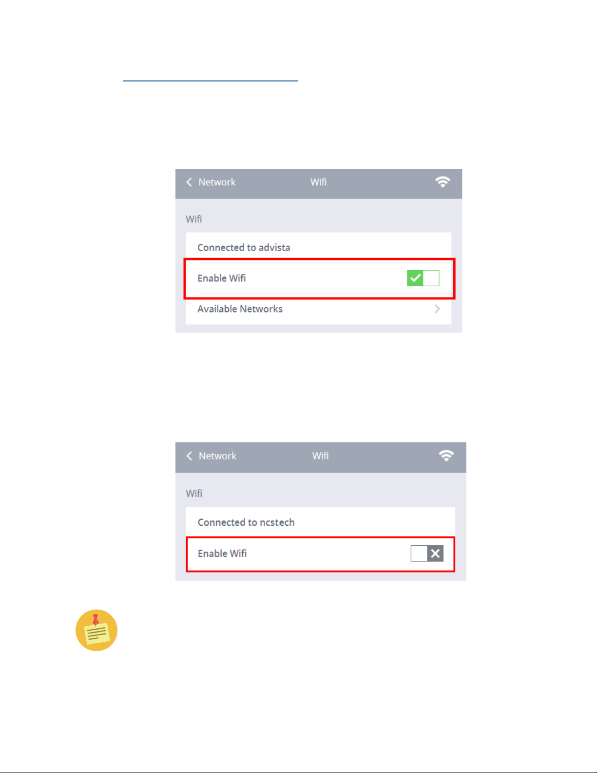
To enable wireless:
1. Click the Network submenu.
2. Select WiFi.
3. Click the Enable WiFi selection box. A green check mark signifies that
WiFi has been enabled.
To disable wireless:
1. Click the Network submenu.
2. Select WiFi.
3. Click the Enable WiFi selection box.. A gray “X” signifies that WiFi has
been disabled.
If both a wired and a wireless network are present, wired will take priority
based on its better performance over WiFi.
52 Cirrus LT Plus User Manual v1.2 - Chapter 4
Page 53
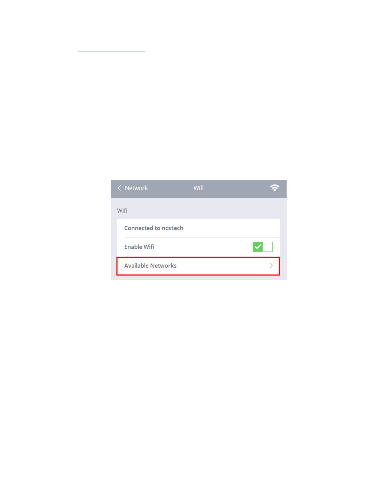
Available Networks
You can see all the available WiFi networks with this option. You can click
on the WLAN you would like to connect to and then enter the password for
the WLAN. Remember to check the Save Connection check box if you would
like to save this information for future convenience (you can disable this feature in the Administrator Menu). Available wireless networks are sorted by
signal strength. WLANs that have higher signal strength are at the top of the
list, while low signal strength WLANs can be found at the bottom of the list.
To see Available Networks:
1. Click the Network submenu.
2. Select WiFi.
3. Click Available Networks.
Cirrus LT Plus User Manual v1.2 - Chapter 4
53
Page 54

4. Choose the network you wish to connect to.
Networks that do not broadcast their SSID will be placed at the bottom of
the list and labeled as “Join Other Network.” You will then have to provide
the SSID, password, and security protocol.
54 Cirrus LT Plus User Manual v1.2 - Chapter 4
Page 55
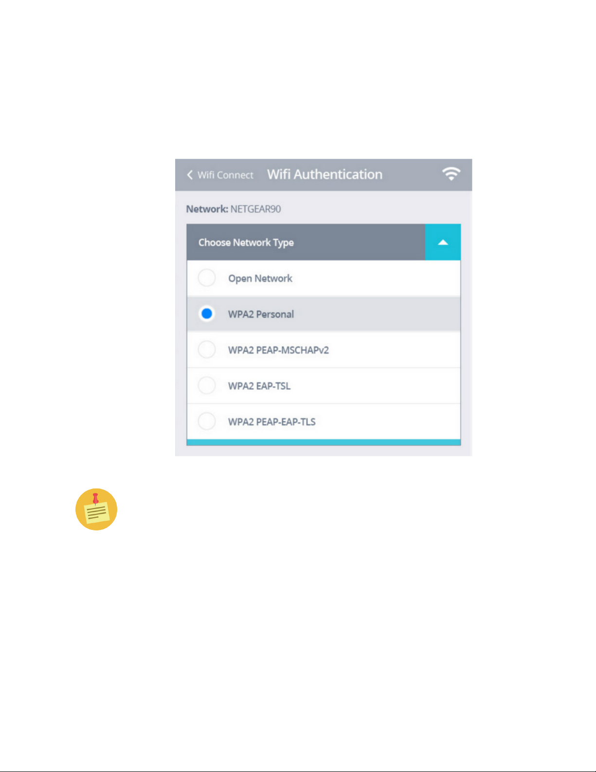
5. Choose the Network Type from the top drop down list.
When selecting a network from the available networks list, the OSM
will automatically detect the proper network type. You only need to
select the network type of hidden networks.
When making wireless connections the Cirrus LT Plus only supports WPA2
and higher levels of security. This system does not support WEP due to its
many security flaws.
Cirrus LT Plus User Manual v1.2 - Chapter 4
55
Page 56
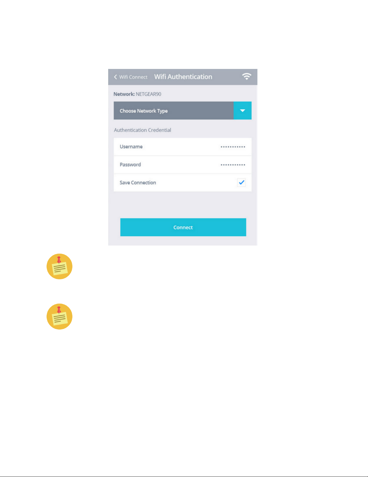
6. Type in your authentication credentials, and click Connect, as shown
below.
IMPORTANT: The maximum password length is 64 characters.
IMPORTANT: you cannot use certain characters in the wireless network
name (SSID) and you cannot use certain characters in your password. See
below for a list of supported and unusable characters:
Supported SSID Characters: letters, numbers, space, symbols including:
~ ` ! @ $ % ^ * ( ) - _ = [ { ] } | ; : ’ , < . > / ?
Symbols printed on the English keyboard that are not supported in SSID
are:
& # + \ “
56 Cirrus LT Plus User Manual v1.2 - Chapter 4
Page 57
Supported Password Characters: letters, numbers, space, symbols including:
` ~ ! @ # $ % ^ & * ( ) - _ = + [ { ] } | ; : ’ , < . > / ?
Symbols printed on English keyboard that are not supported in password are:
\ “
Unicode and non-english letters haven’t been tested, and will probably not be
supported.
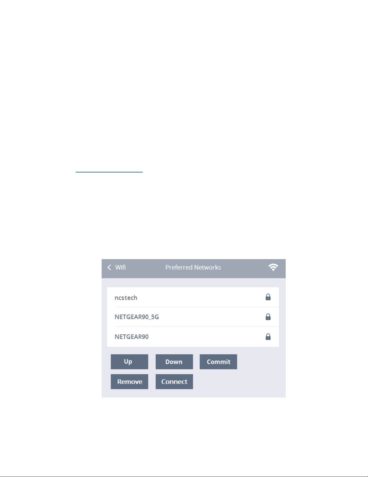
Preferred Networks
Your preferred wireless networks are shown in this list. You can remove or connect to one of these networks by clicking on the chosen network and then either
clicking Remove or Connect.
To see your preferred networks:
1. Click the Network submenu.
2. Select WiFi.
3. Click Preferred Networks.
Cirrus LT Plus User Manual v1.2 - Chapter 4
57
Page 58
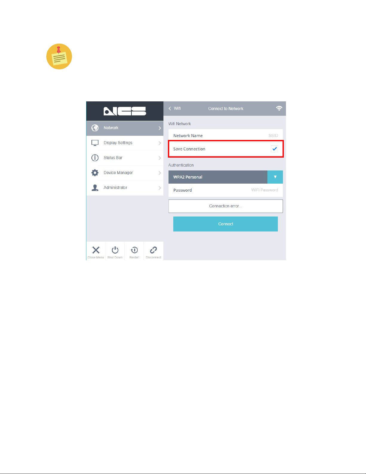
If for some reason this section is always blank, you need to enable “Allow
Saving WiFi Password” in the System Admin Section. This will add a new
check box when signing onto WiFi networks labeled “Save”. By checking this
check box you will be adding this WiFi network as a preferred network. If
you would also like to auto connect to that network, you must select the auto
connect check box in the WiFi Networking Menu.
58 Cirrus LT Plus User Manual v1.2 - Chapter 4
Page 59
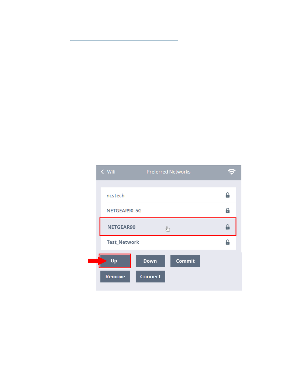
Prioritizing Your Preferred Networks
Your preferred wireless networks are shown in this list. You can move them
up and down in order to prioritize them.
To prioritize your preferred networks:
1. Click the Network submenu.
2. Select WiFi.
3. Click Preferred Networks.
4. Use the mouse cursor (shown below) to select the Network you wish to
move up or down the list. Once you click on the Network, the selected
row will be highlighted in grey. Click the Up or Down button the number of times it will take to move the highlighted server to the desired
position on the list.
5. In the example below, ‘NETGEAR90’ (now in 3rd position) is to be
moved to first on the list. Select it and then click the Up button two
times.
Cirrus LT Plus User Manual v1.2 - Chapter 4
59
Page 60
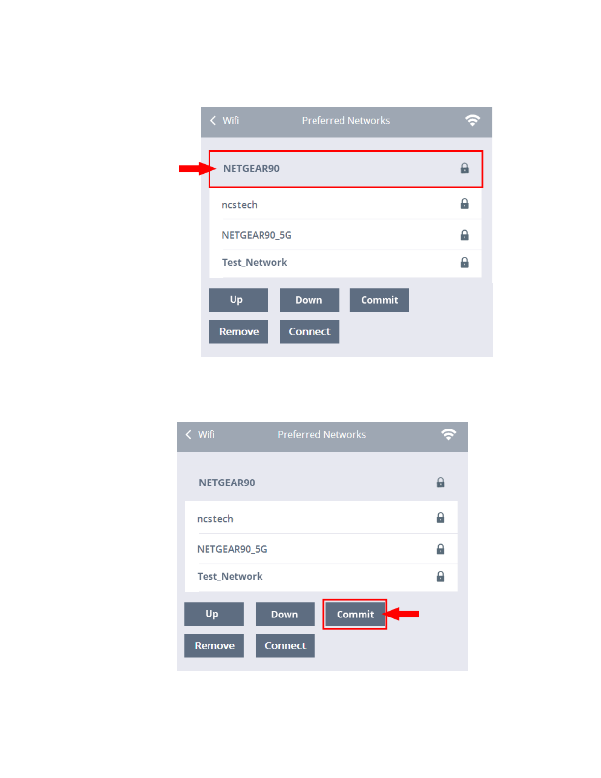
6. Note that ‘NETGEAR90’ is now in 1st position. You can select other
Networks to be moved up or down the list as needed.
7. Once you are done prioritizing your preferred networks, click the Com-
mit button to finalize the changes.
60 Cirrus LT Plus User Manual v1.2 - Chapter 4
Page 61
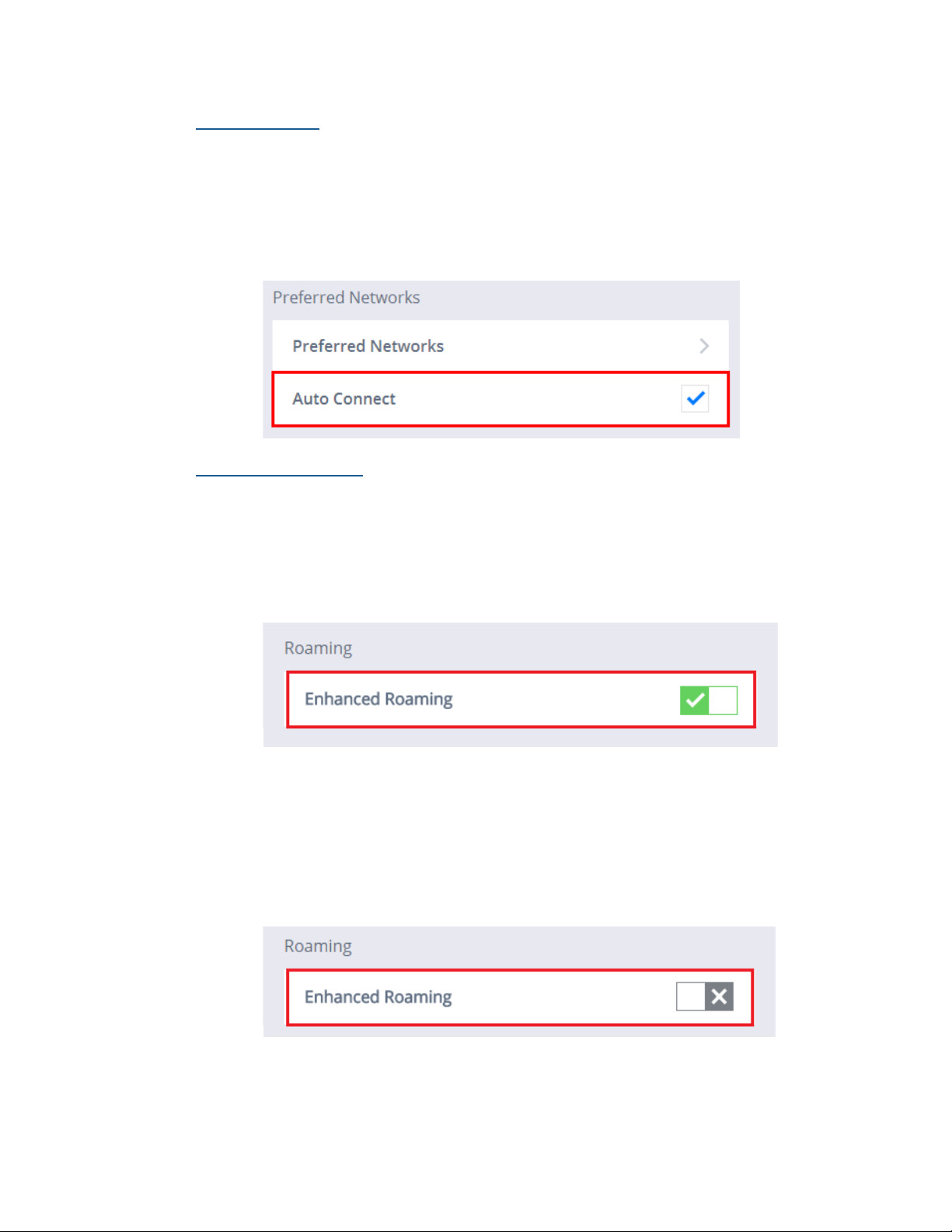
Auto Connect
To enable an automatic connection:
1. Click the Network submenu.
2. Select WiFi.
3. Click the box next to Auto Connection. A blue check mark indicates that
an automatic connection has been enabled.
Enhanced Roaming
To enable Enhanced Roaming:
1. Click the Network submenu.
2. Select WiFi.
3. Click the Enable Enhanced Roaming selection box. A green check mark
signifies that WiFi has been enabled.
To disable Enhanced Roaming:
1. Click the Network submenu.
2. Select WiFi.
3. Click the Enable Enhanced Roaming selection box. A gray “X” signifies
that WiFi has been disabled.
Cirrus LT Plus User Manual v1.2 - Chapter 4
61
Page 62
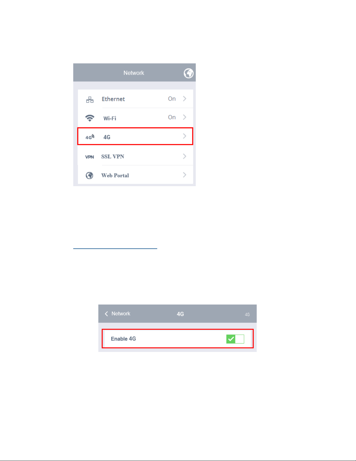
4G
Before you can connect your Cirrus LT Plus via 4G, a SIM card must be installed
into the notebook. Refer to Chapter 2 for more information on how to install a
SIM card.
Enabling and disabling 4G
To enable 4G:
1. Click the Network submenu.
2. Select 4G.
3. Click the Enable 4G selection box. A green check mark signifies that 4G
has been enabled.
62 Cirrus LT Plus User Manual v1.2 - Chapter 4
Page 63
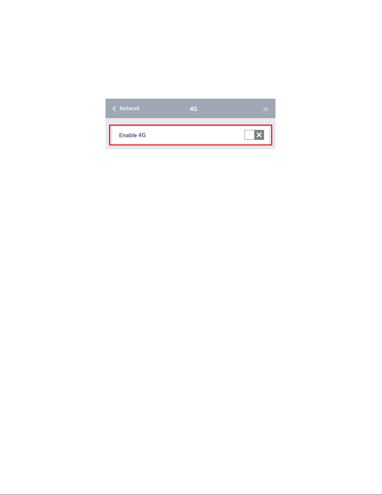
To disable 4G:
1. Click the Network submenu.
2. Select 4G.
3. Click the Enable 4G selection box. A gray “X” signifies that 4G has been
turned off, as shown below.
Cirrus LT Plus User Manual v1.2 - Chapter 4
63
Page 64
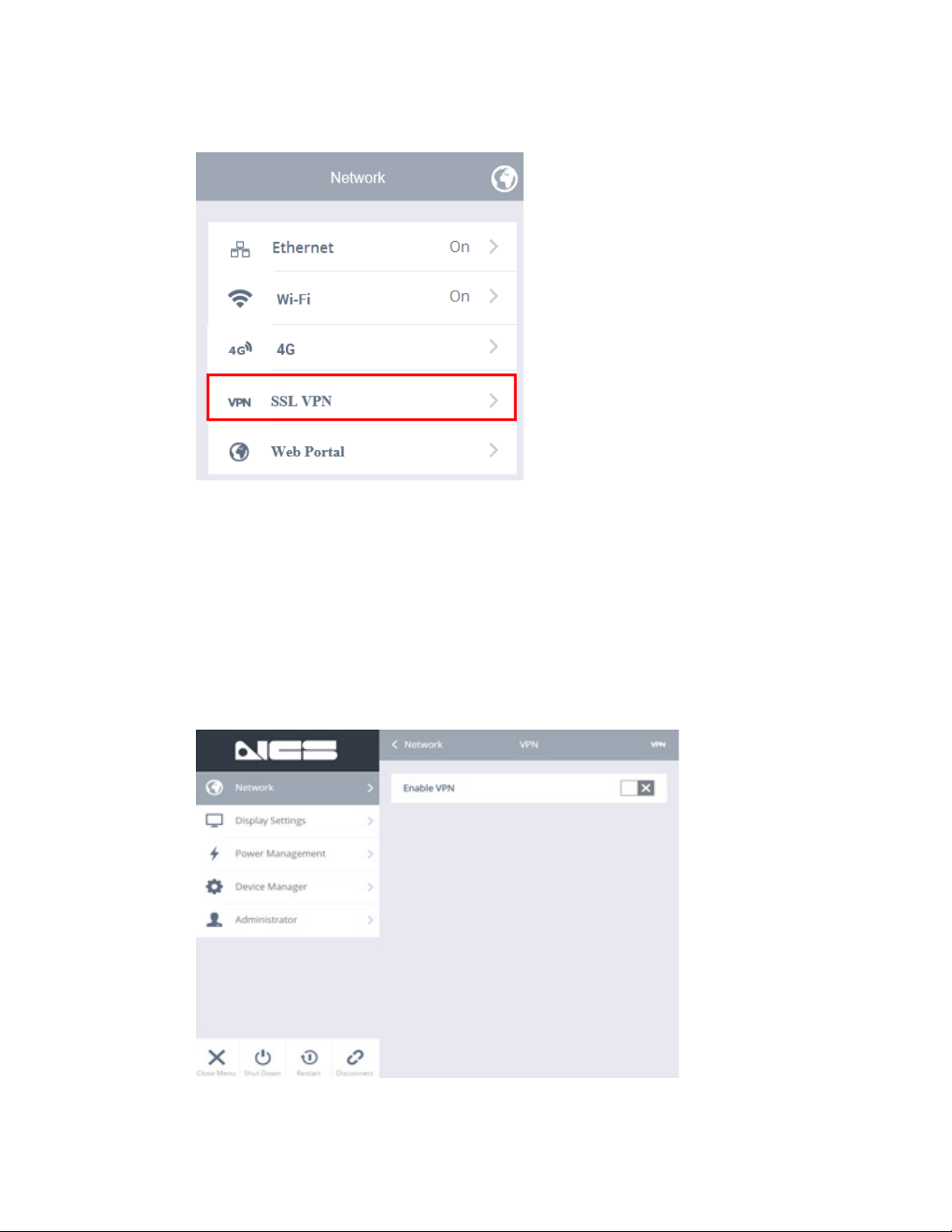
SSL VPN
Enabling SSL VPN will put your Cirrus LT Plus into a special VPN mode, allowing you to connect back to your office’s network through a VPN server. It is im-
portant to note that while in “VPN MODE” the Cirrus LT Plus will be only able
to make remote connections via VPN. Normal connections that do not require
a VPN will not be possible. To connect again to remote connections that do
not require VPN (e.g. when you are at your corporate office), you will need to
DISABLE this feature. Cirrus LT Plus currently only supports Cisco and Juniper
VPN connections.
64 Cirrus LT Plus User Manual v1.2 - Chapter 4
Page 65
Enabling and Disabling SSL VPN
Enabling SSL VPN
To enable SSL VPN:
1. Click the Network submenu.
2. Select SSL VPN.
3. Click the Enable VPN selection box.
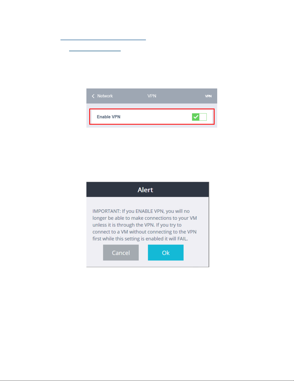
4. An alert (shown below) will then appear. It states that while Enable
VPN is active, the Cirrus LT Plus can only make remote connections
via VPN. Normal connections that don’t need VPN (e.g. when you are
at your corporate office) won’t be possible. To allow remote connections that don’t require VPN, turn off Enable VPN mode.
Cirrus LT Plus User Manual v1.2 - Chapter 4
65
Page 66
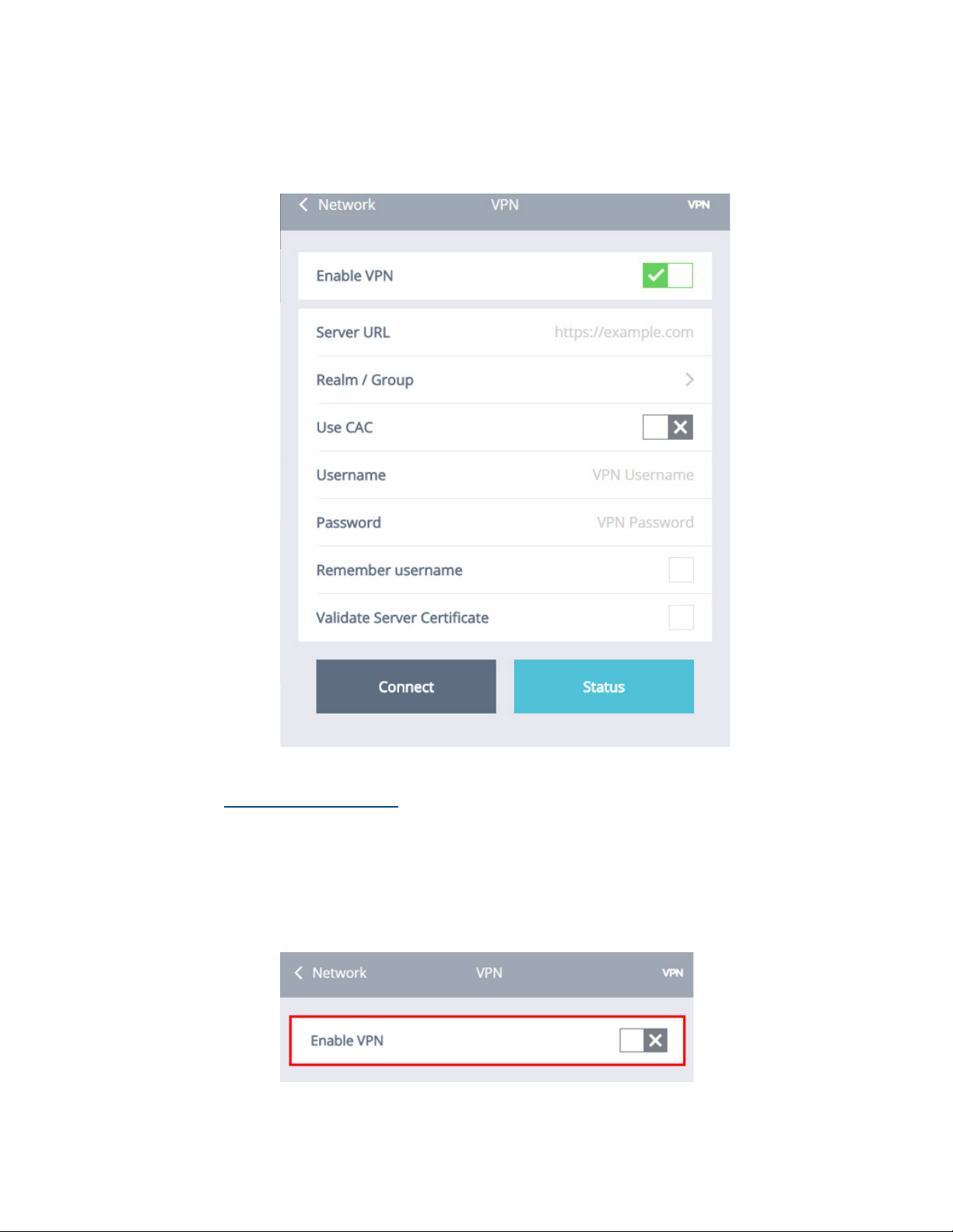
5. Click ‘OK’. The green check mark signifies that VPN has been enabled.
6. Once Enable VPN is turned on, the Network > SSL VPN submenu will
look like this.
Disabling SSL VPN
To disable SSL VPN:
1. Click the Network submenu.
2. Select SSL VPN.
3. Click the Enable VPN selection box. A gray “X” signifies that VPN has
been turned off, as shown below.
66 Cirrus LT Plus User Manual v1.2 - Chapter 4
Page 67
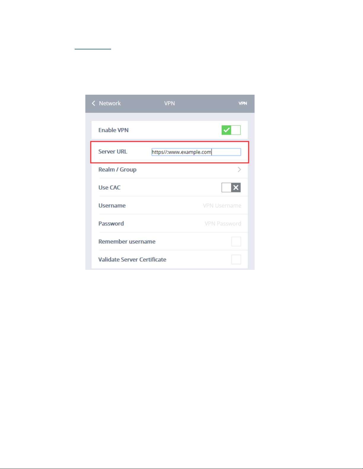
Server URL
In order to connect to a VPN Server, type in its URL or IP Address in the
Server URL field (as shown below), then click the Connect button. For convenience, once a VPN server address is entered it will remain in this field until
changed. Only one VPN server can be stored at this time.
Cirrus LT Plus User Manual v1.2 - Chapter 4
67
Page 68
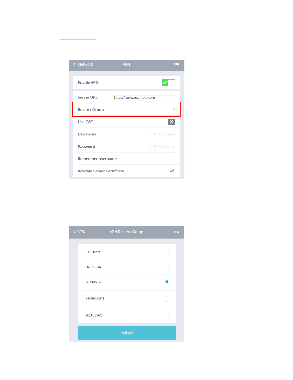
Realm/Group
Once a VPN connection is made, the Cirrus LT Plus will poll the VPN server
for any stored realms or groups.
Clicking on Realm/Group will take you to another screen (shown below) that
lists the reported realms/groups on the VPN server. Select your realm/group
as per instructions from your system administrator. If you don’t see the correct realm/group on the list, click the Refresh button.
68 Cirrus LT Plus User Manual v1.2 - Chapter 4
Page 69

2nd Factor Authentication
Two factor authentication is becoming more and more popular to further
secure remote connections. Cirrus LT Plus supports a number of 2nd factor authentication methods. If you are using any of the following 2nd factor
authentication methods, the Cirrus LT Plus will ask you additional questions
after you initially submit your logon credentials.
Currently supported 2nd factor authentication methods include:
• DuoSecurity - https://www.duosecurity.com/
• Entrust Grid Cards (with Juniper VPN only) - http://www.entrust.com/
gridcard/
• CAC Cards
Cirrus LT Plus User Manual v1.2 - Chapter 4
69
Page 70
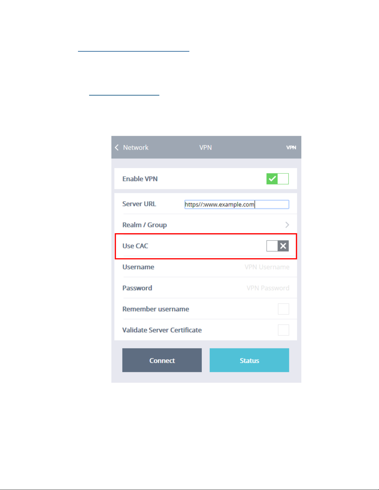
Enabling and Disabling Use CAC
If you are required to use your CAC card to make your VPN connection you
need to enable this feature.
Enabling Use CAC
To enable Use CAC:
1. Click the Network submenu.
2. Select Use CAC.
70 Cirrus LT Plus User Manual v1.2 - Chapter 4
Page 71
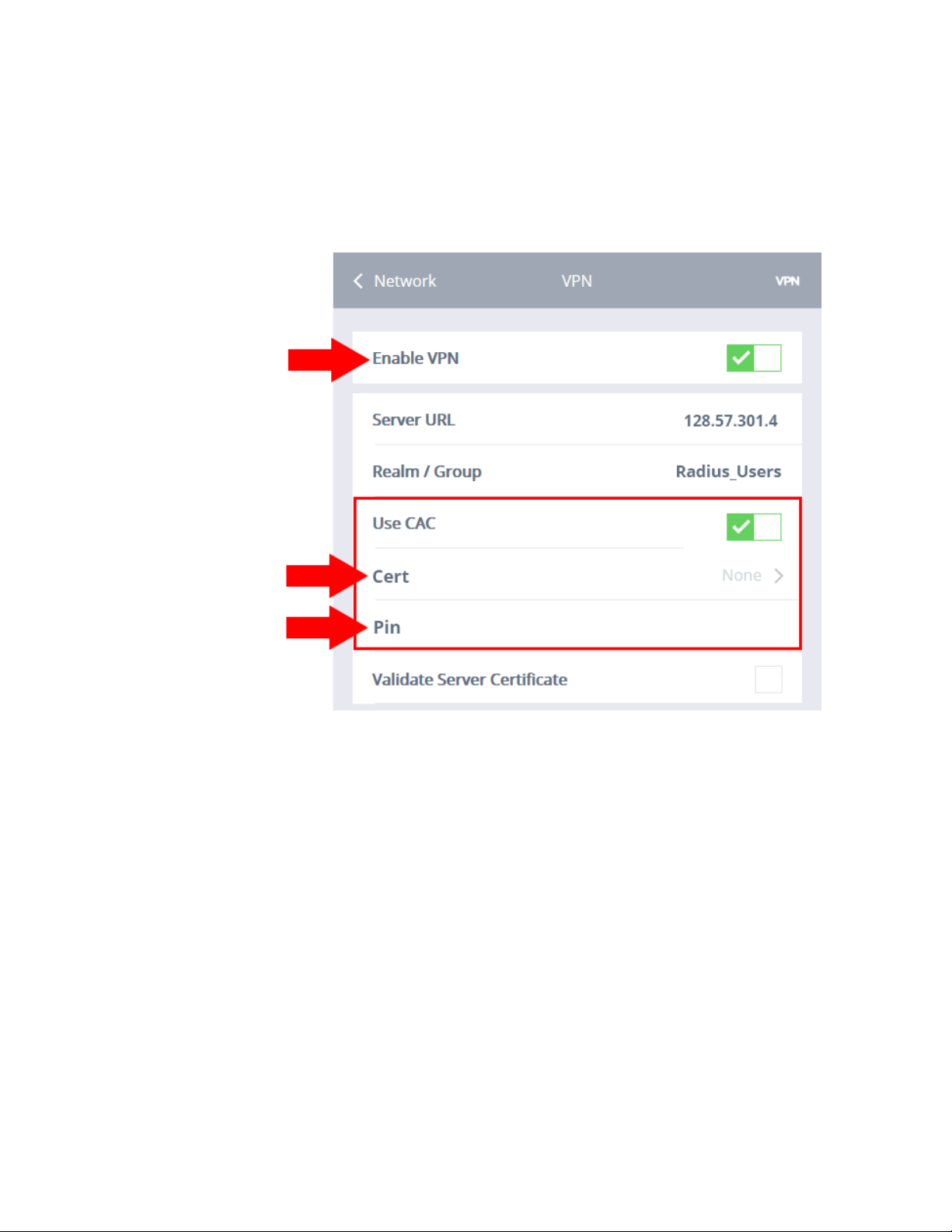
3. Click the Use CAC selection box. A green check mark signifies that Use
CAC has been enabled.
4. When Use CAC is enabled, the highlighted portion (shown below) of
the Network > SSL VPN submenu will display additional fields named
Certificate and Pin.
Cirrus LT Plus User Manual v1.2 - Chapter 4
71
Page 72
Cert
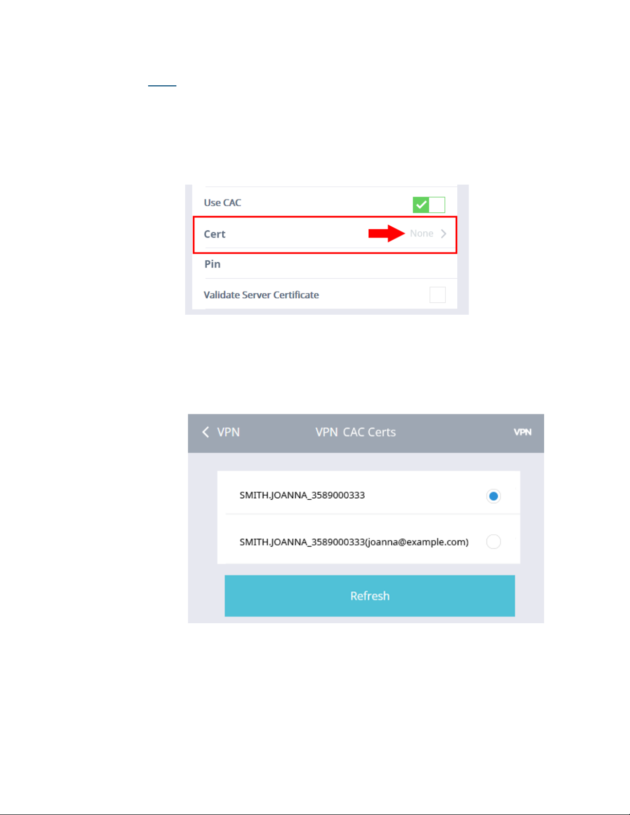
1. Since there can be many different certificates on a CAC card, you will
need to tell Cirrus LT Plus which certificate to use to connect to the
VPN. If you are unsure which certificate to use, you can ask your system administrator. To view a list of certificates to choose from, click on
Cert, as shown below.
2. Once you click on Cert, it will take you to another screen (shown below) that lists the available certificates for you on the CAC card. Select
the Certificate as per instructions from your system administrator. If
you don’t see the correct Certificate on the list, click the Refresh button.
72 Cirrus LT Plus User Manual v1.2 - Chapter 4
Page 73
Pin
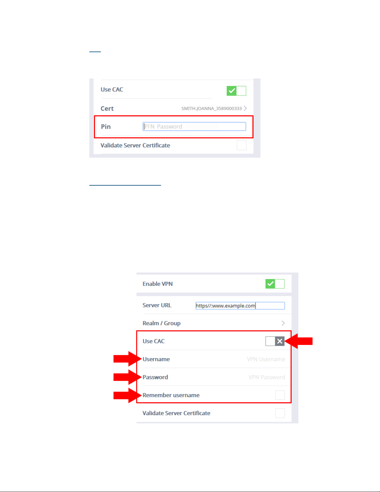
Once you have selected a certificate, return to the Network > SSL VPN submenu and enter the PIN number in the field labeled Pin, as shown below.
Disabling Use CAC
To disable Use CAC:
1. Click the Network submenu.
2. Select SSL VPN.
3. Click the Use CAC selection box. A gray “X” signifies that Use CAC has
been turned off, as shown below.
4. When Use CAC is disabled, the highlighted portion (shown below) of
the Network > SSL VPN submenu will display fields named User Name,
Password, and Remember username.
Cirrus LT Plus User Manual v1.2 - Chapter 4
73
Page 74
Username/Password and Remember Password
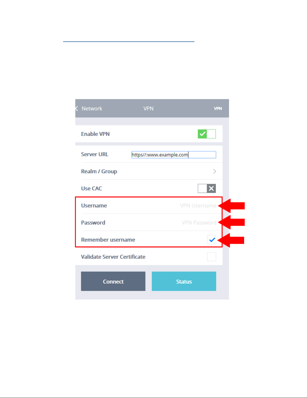
Here is where you will enter your logon credentials. These fields can change
depending on your connection method. For example, if you are using CAC
you will be asked for a PIN instead.
If you would like the GUI to retain your username for convenience, check
the Remember username to enable this feature.
74 Cirrus LT Plus User Manual v1.2 - Chapter 4
Page 75
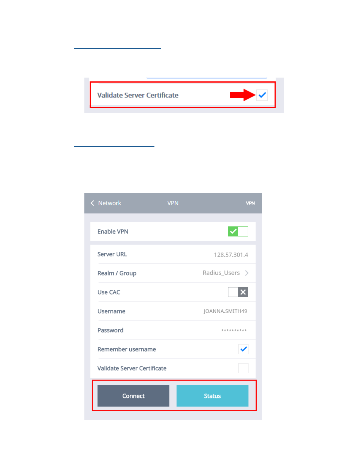
Validate Server Certificate
If your VPN requires the client to validate a server certificate, enable this
feature.
Connect/Status Buttons
Once you are done configuring the SSL VPN setup, click the Connect button
to connect to your VPN Server. Clicking the Status button gives you more
information about your current VPN connection, which may be useful for
troubleshooting and/or admins.
Cirrus LT Plus User Manual v1.2 - Chapter 4
75
Page 76
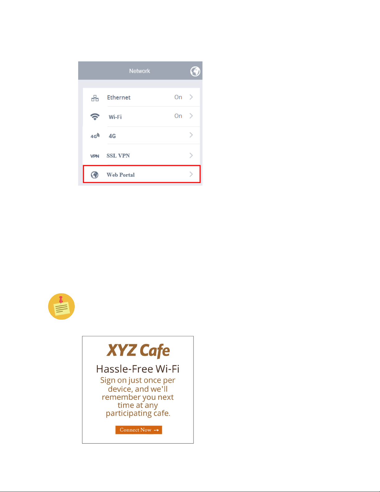
Web Portal
Some public WiFi networks will require you to confirm or authenticate to the
WiFi network via a web page. If this is the case you need to enable the Web
Portal (also known as a Captive Portal) feature under the administrator settings
in order for another window to pop up for you to interact with that WiFi network’s web interface. To connect to a Public WiFi Open Network, you are often
presented with a web page to accept a usage agreement, like the example shown
below. In these cases, Cirrus LT Plus supports most of these types of authentication web pages.
The Cirrus LT Plus’ Network Settings are set to ‘Web Portal’ by default. If
for added security you want to disable this feature, you can in the Administrator submenu, described later in Chapter 4, under the “Administrator”
section.
76 Cirrus LT Plus User Manual v1.2 - Chapter 4
Page 77
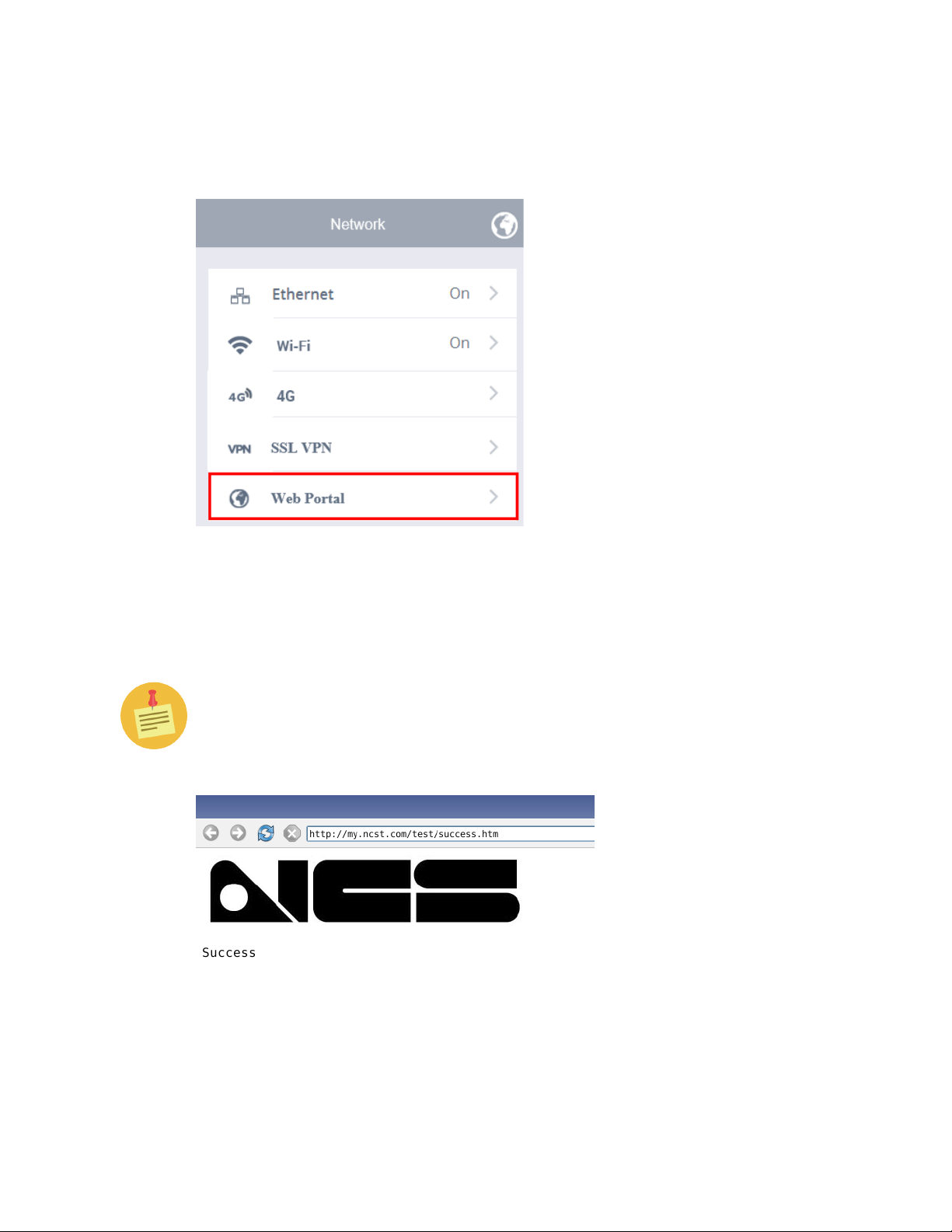
• Ensure you have connected to the open WiFi network and have been assigned
an IP address. Once this is done, click on the Web Portal selection in the Network
Menu.
• If for some reason the network you are on does not have a web portal, Cirrus
LT Plus will take you to a default web page on ncst.com to confirm everything is
working properly and you should be able to do a remote session.
You may need to click REFRESH on the Web Portal to display the web page.
If for added security you want to disable this feature, you can in the Administrator submenu, described later in Chapter 4, under the “Administrator”
section.
NCS strives to support many different types of web portal pages, but unfortunately incompatibilities will arise. In these cases, please enter a support ticket
on NCS’s Support Page with the web page or location that you were not able to
connect to and we will investigate why Cirrus LT Plus was unable to connect.
Cirrus LT Plus User Manual v1.2 - Chapter 4
77
Page 78
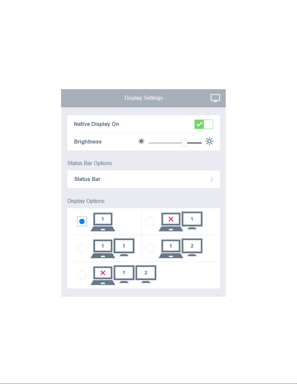
Display Settings
In the Display Settings Menu, you can select the display configuration of the
notebook and adjust display brightness. You may want to disable the native LCD,
if you are using a docking station or miniDP port for video.
78 Cirrus LT Plus User Manual v1.2 - Chapter 4
Page 79
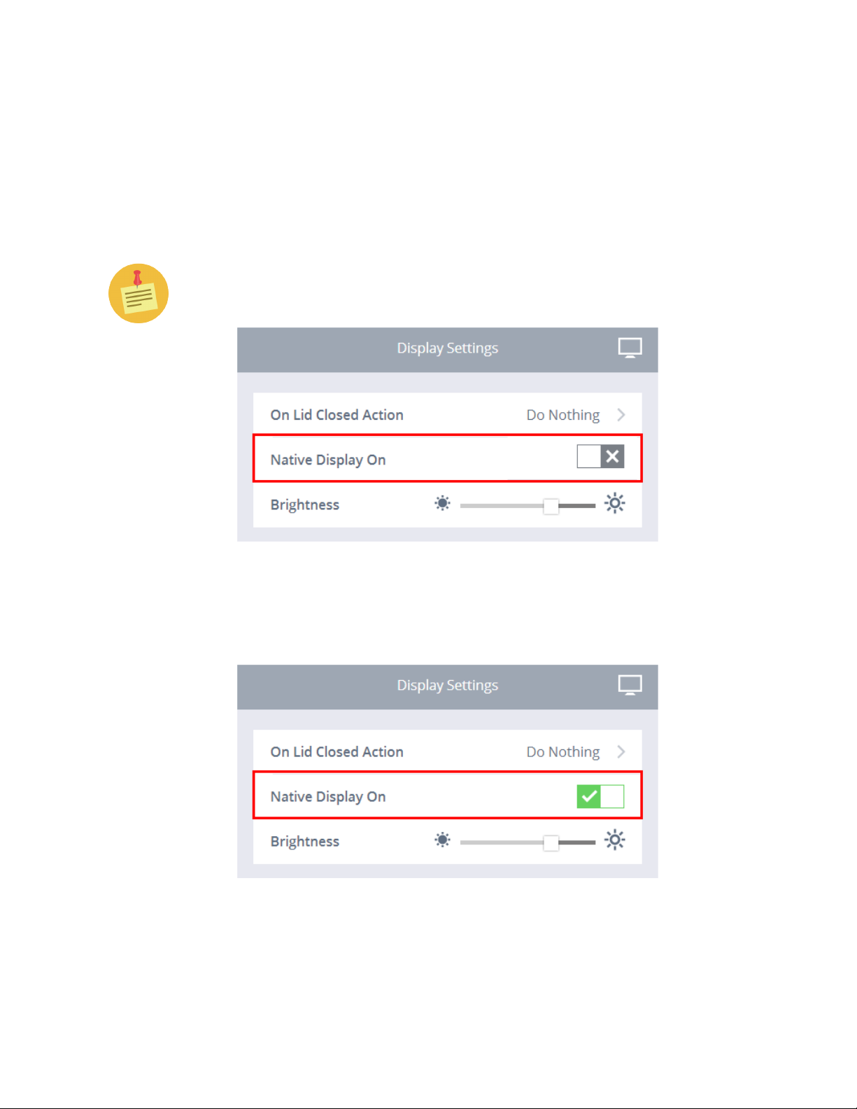
Native Display Off
This feature allows you to turn off the Native Display.
To turn off the Native Display:
1. Click the Display Settings submenu.
2. Click the box next to Native Display On. The Native Display will then
turn off.
You can also toggle the Native Display on and off by pressing Fn-F4.
To turn on the Native Display:
1. To turn on the Native Display select the green check mark, as shown below. Fn-F4 will also toggle the display on/off.
Cirrus LT Plus User Manual v1.2 - Chapter 4
79
Page 80
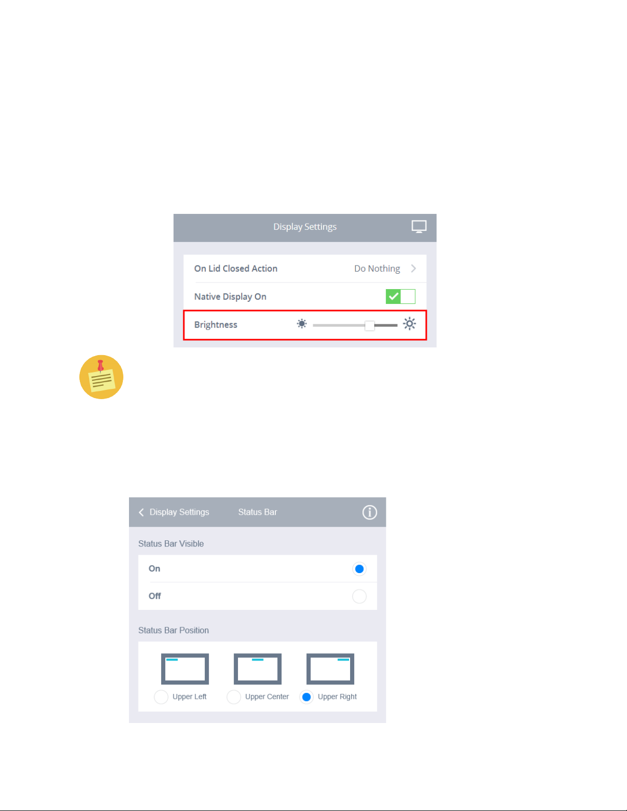
Brightness
To increase or decrease screen brightness:
1. Click the Display Settings submenu.
2. Toggle the Brightness slide left or right until you reach your desired
screen brightness. Moving the slide to the right will increase the brightness, and moving the slide to the left will decrease the brightness. Alternatively, you can decrease screen brightness by pressing Fn-F2 or increase it by pressing Fn-F3.
Lowering the screen brightness can save battery life!
Status Bar
The status bar submenu allows you to control the visibility and position of the
status bar.
80 Cirrus LT Plus User Manual v1.2 - Chapter 4
Page 81
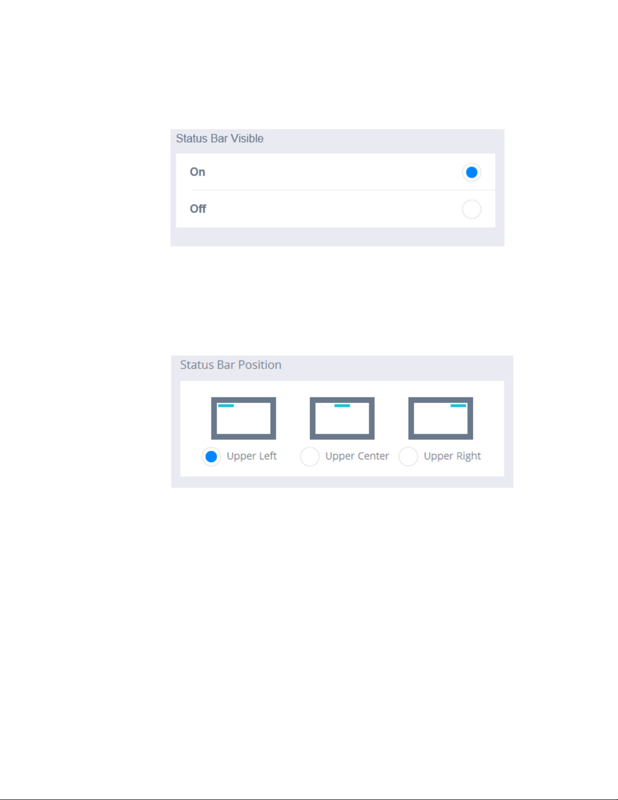
To change the status bar visibility:
1. Click the Status Bar submenu.
2. Under the Status Bar Visible section, choose On or Off.
To change the status bar position:
1. Click the Status Bar submenu.
2. Under the Status Bar Position section, choose Upper Left, Upper Center,
or Upper Right.
Cirrus LT Plus User Manual v1.2 - Chapter 4
81
Page 82
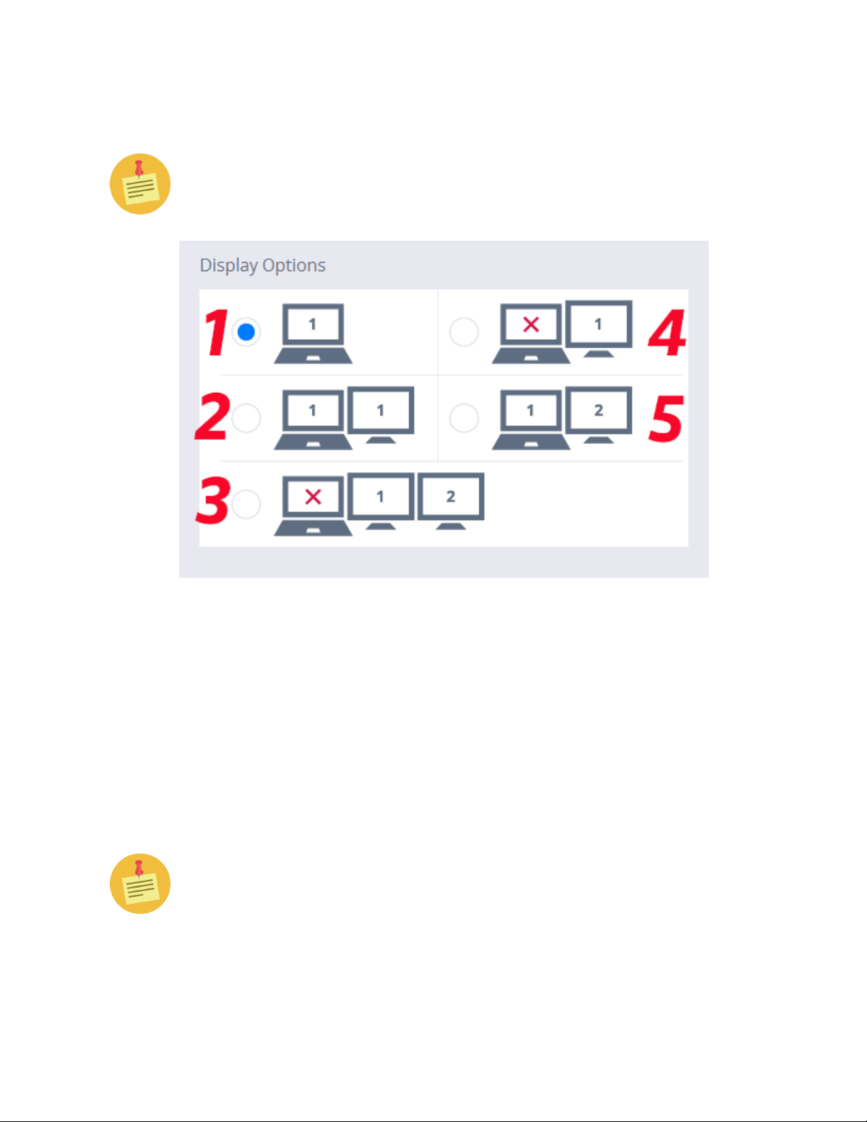
Display Options
IMPORTANT – These settings are to enable the ports to support the following display modes. Further configuration is done with the Teradici Firmware.
The image above corresponds to the numbered configurations below.
Here are the following display configurations you can select:
1. Use Native LCD Display Only
2. Clone Native LCD on Display 1 of docking station
3. Turn off Native LCD; Use Display 1 of docking station, and Display 2 of
the Mini DP port or docking station
4. Use Display 1 on docking station only
5. Use LCD and Display2 of the Mini DP port or docking station
The OSM will only appear on the native display and displays connected to
DVI-1 on the docking station. It cannot be shown on a display attached to
the mini DP Port.
82 Cirrus LT Plus User Manual v1.2 - Chapter 4
Page 83
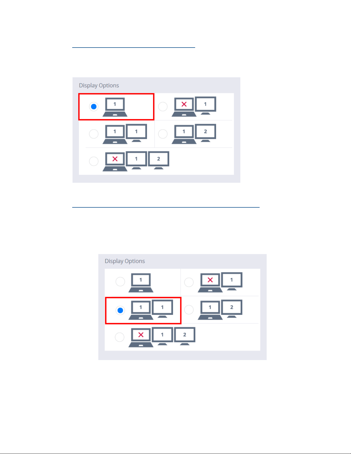
Option 1: Use Native LCD Display Only
This is the Cirrus LT Plus’ default setting and allows sole use of the Cirrus LT
Plus’ notebook display.
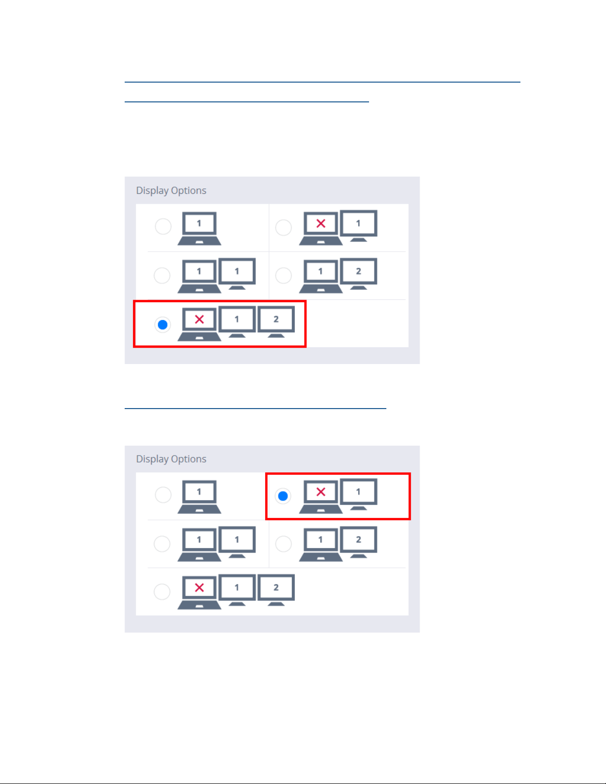
Option 2: Clone Native LCD on Display 1 of docking station
1. In order to Clone your display with a docking station you will need to
connect your laptop into the docking station and then connect an external display to PCoIP1/Local (DVI1) Port. You then select the following
option in the OnScreen Menu, as shown below:
2. This cloning method will duplicate the same display resolution of the
Cirrus LT Plus LCD and is locked to this resolution.
Cirrus LT Plus User Manual v1.2 - Chapter 4
83
Page 84
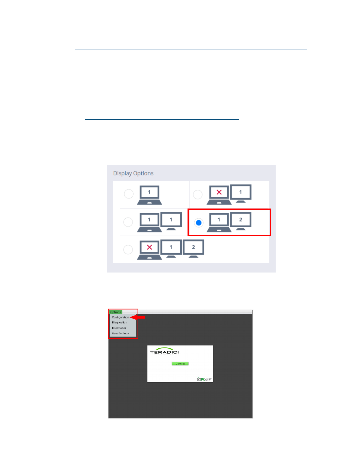
Option 3: Turn off Native LCD; Use Display 1 of docking station, and Dis-
play 2 of the Mini DP port or docking station
This option allows you to close the notebook lid and use Display 2, or have one
display plugged into the docking station and a second mini DP Port for another
screen for an extended desktop.
Option 4: Use Display 1 on docking station Only
Choose this option if you wish to use Display 1 on the docking station only.
84 Cirrus LT Plus User Manual v1.2 - Chapter 4
Page 85
Option 5: Use LCD and Display2 of the Mini DP port or docking station
By default, this option will extend the primary display to Display2. To change
the resolution of Display2 in this configuration, you should alter the settings
present in the Operating System during your session. If you are not using a docking station, you may also use this mode to clone your display and to make mini
DP the primary display by following the steps below.
Cloning displays without a docking station
1. In order to clone two displays without the use of a docking station you
must first attach a display to the mini DP port on the notebook. In the
OSM Menu, navigate to Display Settings and select the following op-
tion, as shown below.
2. Access the Teradici Firmware Configuration Menu, and click Options >
Configuration.
Cirrus LT Plus User Manual v1.2 - Chapter 4
85
Page 86
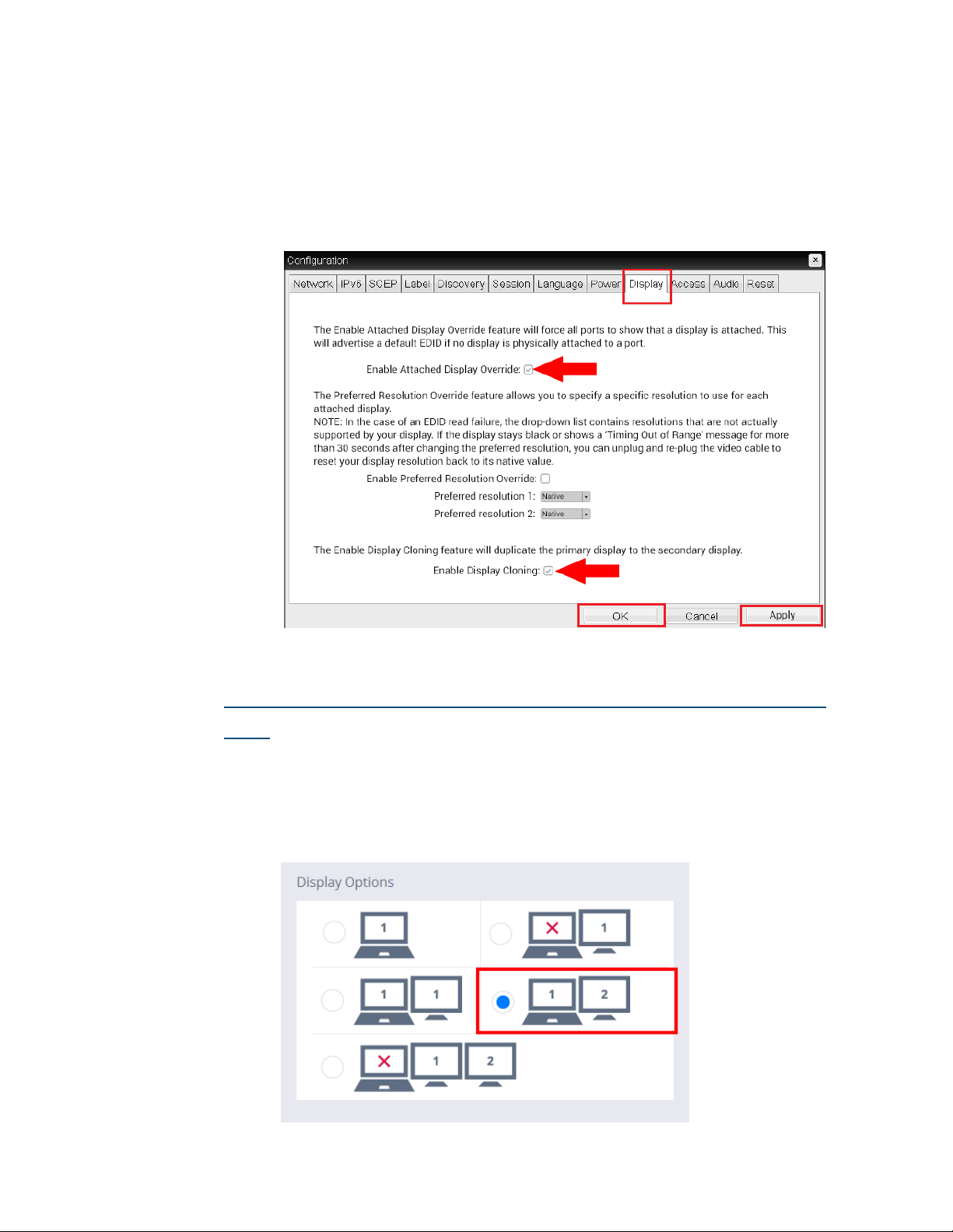
3. Navigate to the Display Tab (shown below) and check the following
boxes:
• Enable Attached Display Override
• Enable Display Cloning
4. Next, Click Apply and then OK.
How to make mini DP the Primary Display (without docking station)
1. In order to make the mini DP the primary display without the use of a
docking station you must first attach a display to the mini DP port on
the notebook. In the OSM Menu, navigate to Display Settings and select
the following option, as shown below.
86 Cirrus LT Plus User Manual v1.2 - Chapter 4
Page 87
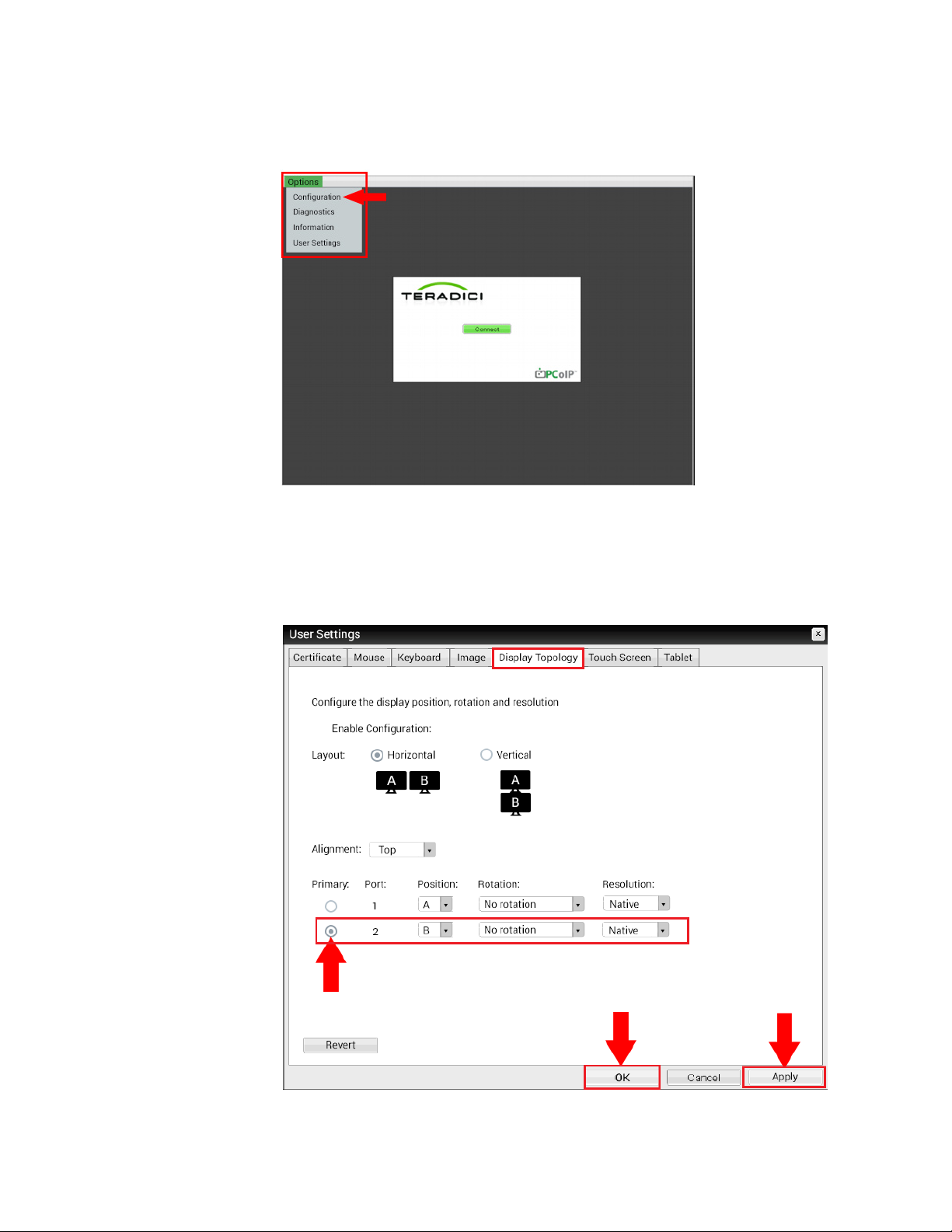
2. Access the Teradici Firmware Configuration Menu, and click Options >
User Settings.
3. Navigate to the Display Topology tab. Check the Primary Port #2.
4. Click ‘Apply’ and then ‘OK’ to close the Teradici Firmware, as shown
below.
Cirrus LT Plus User Manual v1.2 - Chapter 4
87
Page 88
Power Management
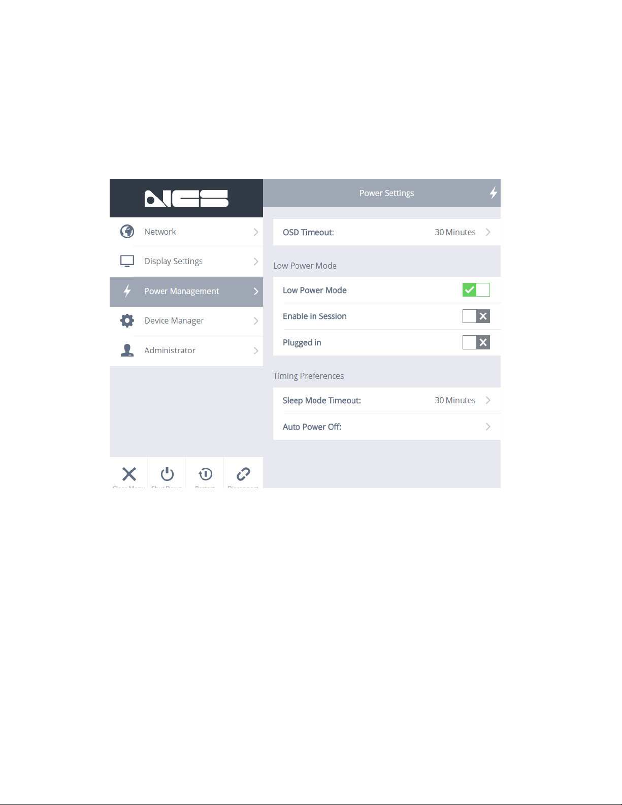
The Power Management Section allows you to customize the Cirrus LT Plus’ OnScreen Menu (OSM) Timeout, determine when Low Power Mode should be enabled, and to choose when Sleep Mode should be enabled.
88 Cirrus LT Plus User Manual v1.2 - Chapter 4
Page 89
Setting the duration of the OnScreen Menu (OSM) Timeout
There are two ways to set the OSM Timeout interval. The first way can be set
within the OSM itself, under Power Management > Power Settings > OSM Time-
out. The second way is via Teradici’s Firmware Menu.
Via the OSM Power Management > Power Settings > OSM Timeout
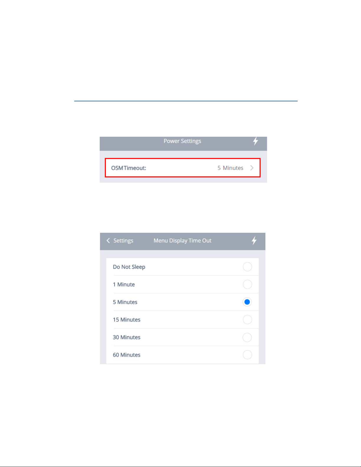
To change the timeout duration via the OnScreen Menu Timeout:
1. Click the Power Management submenu, and then click the OSM Timeout
bar, as shown below.
2. The Menu Display Time Out Section will appear, as shown below. You
may choose between Do Not Sleep, 1 Minute, 5 Minutes, 15 Minutes, 30
Minutes, or 60 Minutes (5 Minutes is the default setting).
3. Select the desired interval and click on ‘Settings’ to return to the Power
Savings Menu.
Cirrus LT Plus User Manual v1.2 - Chapter 4
89
Page 90
Via Teradici’s Firmware Menu
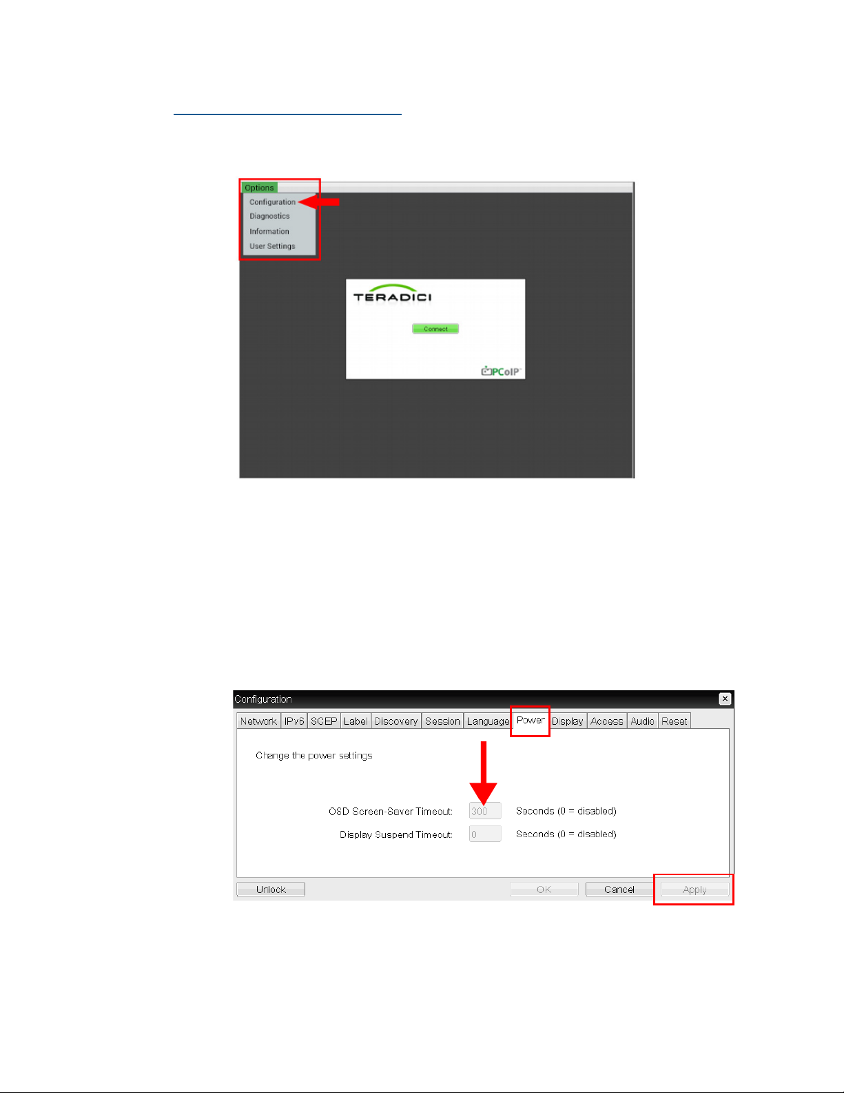
To change the timeout duration via the Teradici Power Menu:
1. From the Teradici main window, select Options > Configuration.
2. Click on the Power Tab.
3. Enter the new duration of the OSM Screen-Saver Timeout in seconds, not
minutes. For example, if you wanted to set the duration to 10 minutes,
you would enter 600 seconds (Teradici’s Firmware OSM Screen-Saver
Timeout default is set to 300 seconds, or 5 minutes). If you enter ‘0’ Seconds, the OSM Screen-Saver Timeout will only be disabled in the Teradi-
ci Firmware.
4. Click the ‘Apply’ button when you are done.
90 Cirrus LT Plus User Manual v1.2 - Chapter 4
Page 91

How the Cirrus LT Plus power management modes are all related
No matter how you customize the Cirrus LT Plus’ Power Management Modes
via the OnScreen Menu Timeout and the Teradici OSD Timeout, the Cirrus LT
Plus follows a pre-determined ‘chain of events’ in certain situations. Familiarizing yourself with these ‘chain of events’ can help you keep the Cirrus LT Plus
Power Management Modes at their optimal settings.
Chain of events
1. After a certain amount of user inactivity the LCD will turn off to conserve
power. This is controlled via the OnScreen Menu Timeout AND/OR the
Teradici OSD Timeout.
If the OSM ‘Menu Display Timeout’ Menu and the Teradici ‘OSM Screen
Saver Timeout’ Menu are set to different intervals, the Cirrus LT Plus will
automatically use the lowest selected interval.
2. Next, if the Low Power modes are enabled, the Sleep mode will activate
after the duration specified.
3. Auto Power Off is the lowest setting available. When Auto Power Off is
configured, the machine will shut off completely after the duration of
this setting has elapsed. However, this duration doesn’t start until after
the machine has entered a lower power mode/gone to sleep. If Wake-on-
LAN is also enabled, it will draw some power to keep the Ethernet port
active. In this Wake-on-LAN mode the Power LED will be solid amber,
otherwise all LEDs will be off.
Teradici has an auto-power off function of their own. It cannot be controlled
in the local firmware options, but can be set in both their management
console and their web portal for clients. This overrides all other settings - if
it’s set to 60 seconds, the device will turn off in 60 seconds after inactivity
regardless of other settings in place.
Cirrus LT Plus User Manual v1.2 - Chapter 4
91
Page 92

How the Cirrus LT Plus detects inactivity
Cirrus LT Plus only detects inactivity by the LCD turning off (not by user inactivity).
There are two ways that the LCD will turn off due to inactivity.
1. If the OSM ‘Menu Display Timeout’ Menu is set to a value of X minutes,
and the OSM is left open and there is no mouse or keyboard activity for a
duration greater than X, the LCD will turn off.
2. If the Teradici ‘OSM Screen Saver Timeout’ Menu is set to X seconds, and
there is no mouse or keyboard activity for a duration greater than X seconds the LCD will turn off.
More about the OnScreen Menu’s ‘Do Not Sleep’ option
If ‘Do Not Sleep’ is enabled AND the Teradici OSD Timeout Menu
is enabled
Setting the OnScreen Menu (OSM) Timeout’ to Do Not Sleep (as shown be-
low) may disable the other power management features (Sleep Mode Timeout
and Auto Power Off).
92 Cirrus LT Plus User Manual v1.2 - Chapter 4
Page 93
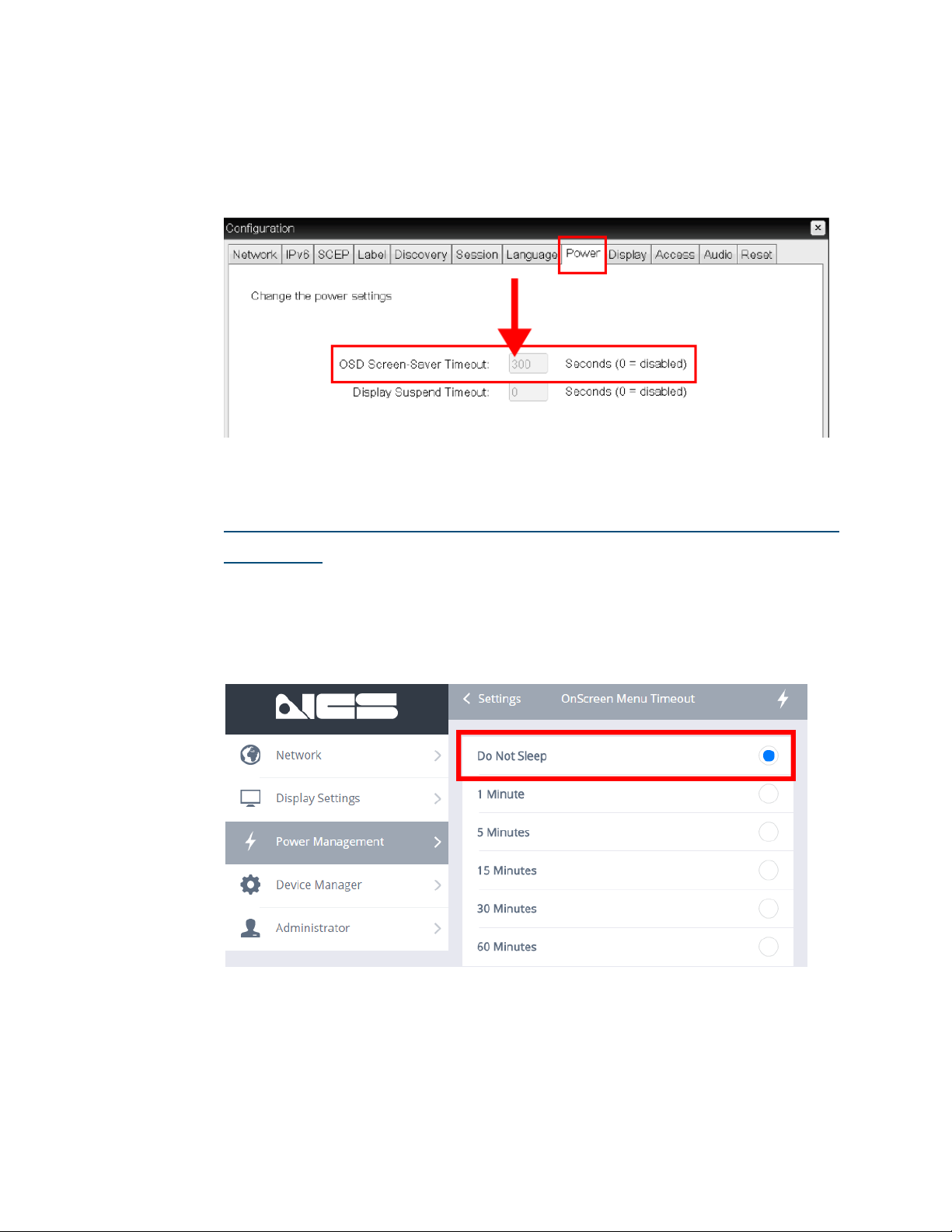
However, if the OSM Timeout is set to Do Not Sleep, but the Teradici OSD
Timeout Menu is enabled (as shown below, the ‘OSD Screen Saver Timeout’
is set to any value that is not 0), the other Power Management features (Sleep
Mode Timeout and Auto Power Off) will not change.
If ‘Do Not Sleep’ is enabled AND the Teradici OSD Timeout Menu
is disabled
If for some reason both the OnScreen Menu Timeout AND the Teradici OSD
Timeout values are disabled (as shown below), this will disable all Cirrus LT
Plus Power Management features (including Sleep Mode Timeout and Auto
Power Off) even if they are set to ‘enabled’.
Cirrus LT Plus User Manual v1.2 - Chapter 4
93
Page 94
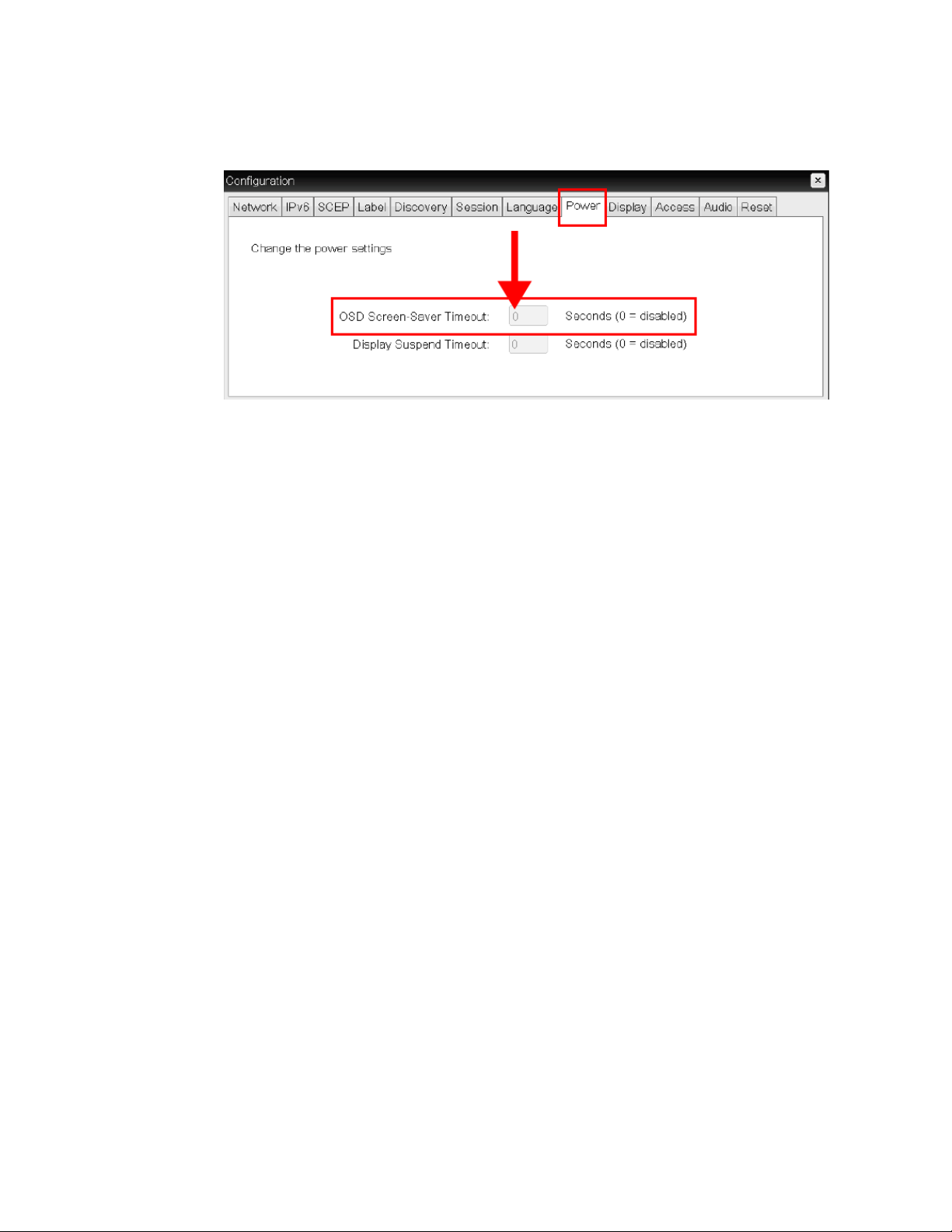
Below is a screenshot of the Teradici OSD Timeout when it is disabled (because the value is set to 0).
As stated before, when OSM’s ‘Do Not Sleep’ is enabled AND the Teradici
OSD Timeout Menu is turned off, all of Cirrus LT Plus Power Management
features will be disabled and the Cirrus LT Plus may not run optimally. En-
suring that the OnScreen Menu Timeout AND the Teradici OSD Timeout
value are both enabled will save energy and automatically turn off the LCD
when it is supposed to.
94 Cirrus LT Plus User Manual v1.2 - Chapter 4
Page 95
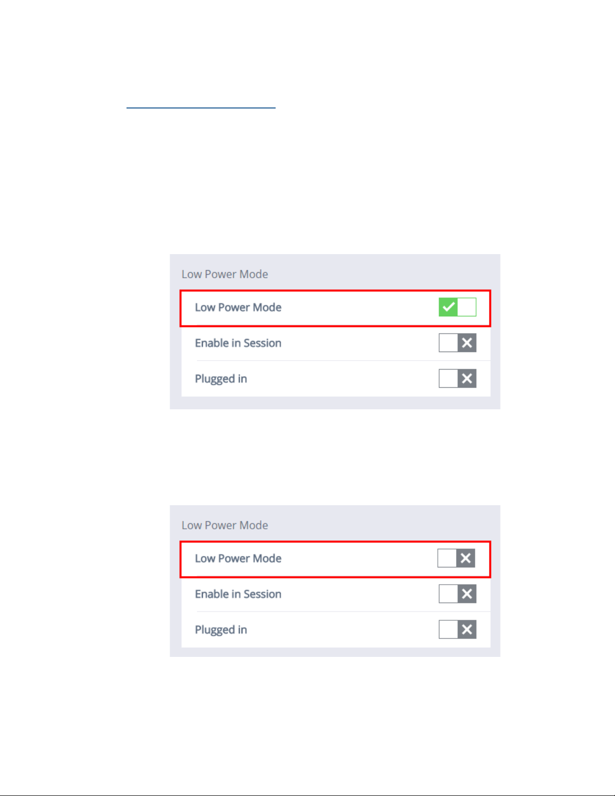
Low power mode
Enabling Low Power Mode
Turning on Low Power Mode will enable the two low power modes (Sleep Mode
and Auto Power Off). If Low Power Mode is turned off, Sleep Mode and Auto
Power Off will turn off and the unit will not enter sleep mode.
To turn on Low Power Mode:
1. Click the Power Management submenu.
2. Click the box next to Low Power Mode. When the green ‘check mark’ is
selected, Low Power Mode will then be enabled.
To turn off Low Power Mode:
1. Click the Power Management submenu.
2. Click the box next to Low Power Mode. When the gray ‘x’ is selected, Low
Power Mode will be disabled.
Cirrus LT Plus User Manual v1.2 - Chapter 4
95
Page 96
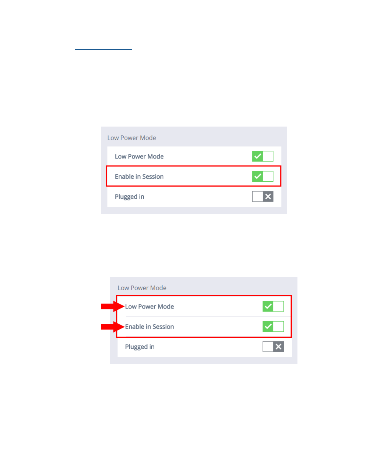
Enable in Session
Enabling this mode will put the unit to sleep within the selected amount of time
of inactivity even if in a remote session.
To Enable In Session Mode:
1. Click the Power Management submenu.
2. Click the box next to Enable In Session. When the green ‘check mark’ is
selected, Enable In Session Mode will then be turned on.
If Enabling In Session and Low Power Mode are both turned on:
1. When Enable In Session and Low Power Mode are enabled simultaneous-
ly (as shown below),the low power modes Sleep Mode and Auto Power Off
will work even while connected to a remote host.
96 Cirrus LT Plus User Manual v1.2 - Chapter 4
Page 97
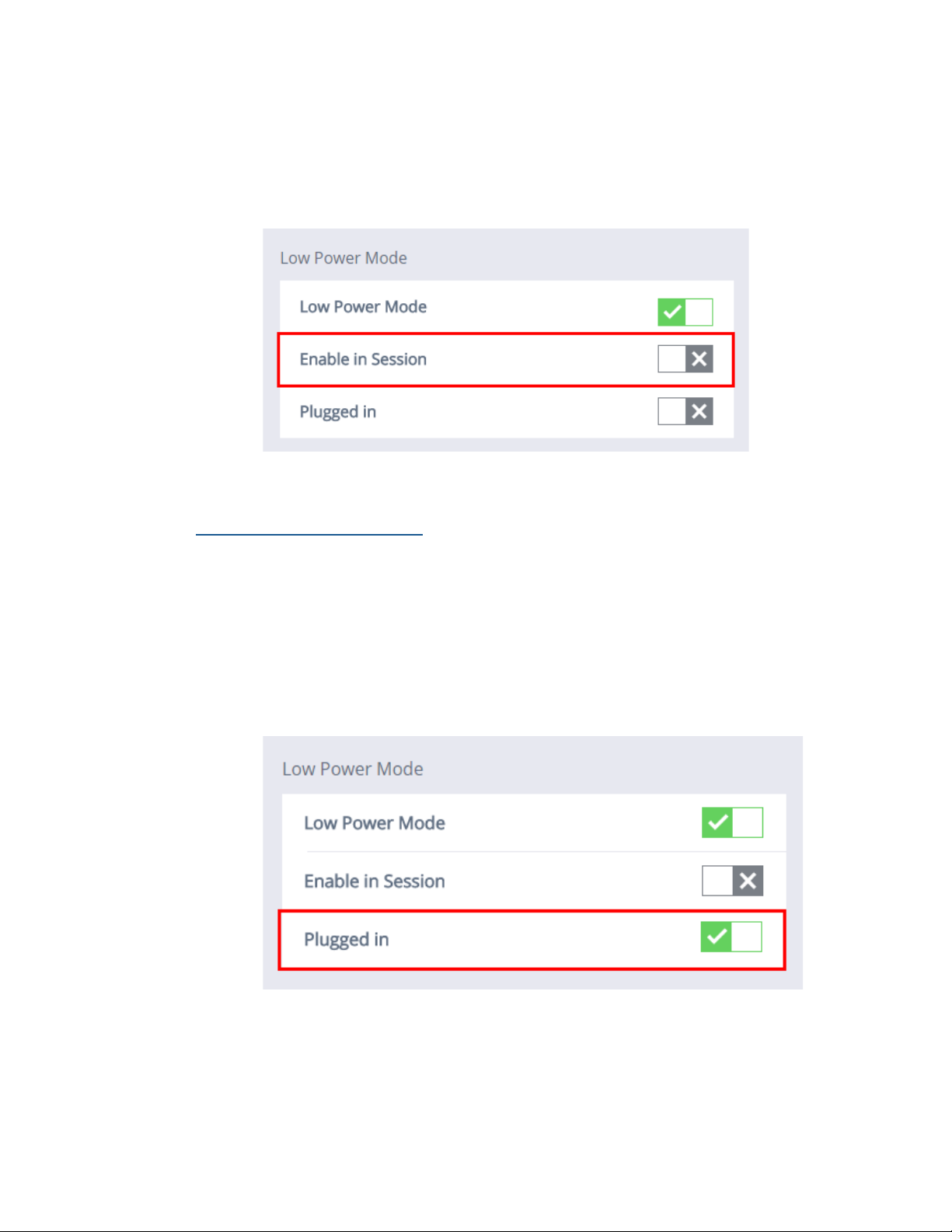
To Disable In Session Mode:
1. Click the Power Management submenu.
2. Click the box next to Enable In Session. When the gray ‘x’ is selected, En-
able In Session Mode will be turned off.
Enabling Plugged In Mode
With this mode enabled, the unit will go to sleep in the selected time of inactivity even with the power cord plugged into an AC outlet.
To Enable Plugged In Mode:
1. Click the Power Management submenu.
2. Click the box next to Plugged In. When the green ‘check mark’ is selected,
Plugged In Mode will be enabled.
Cirrus LT Plus User Manual v1.2 - Chapter 4
97
Page 98
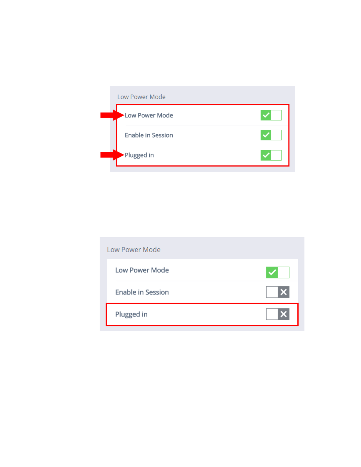
If Enabling Plugged In Mode and Low Power Mode are both turned on:
1. When Plugged In Mode and Low Power Mode are simultaneously enabled
(as shown below), the low power modes Sleep Mode and Auto Power Off
will work even while connected to a remote host.
To Disable Plugged In Mode:
1. Click the Power Management submenu.
2. Click the box next to Plugged In Mode. When the gray ‘x’ is selected,
Plugged In Mode will be disabled.
98 Cirrus LT Plus User Manual v1.2 - Chapter 4
Page 99
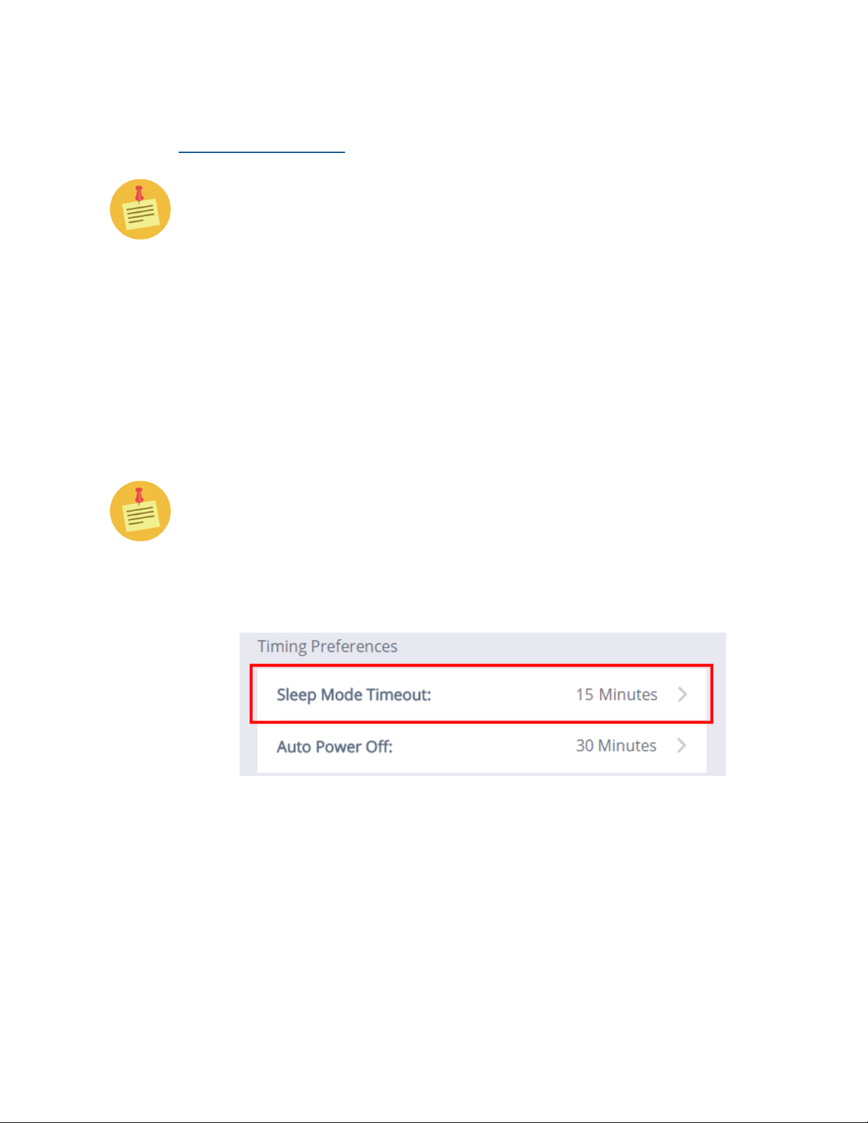
Timing preferences
Sleep Mode Timeout
Please read the caution above in the ‘How the Cirrus LT Plus Power Management Modes Are All Related’ section above before customizing this
mode.
Enabling Sleep Mode Timeout will save considerable power by turning off both
the LCD and Teradici processor. It will also put other components into a lower
power state. The Power LED will blink green and amber and then finally just
blink amber when it has gone into low power mode. You will need to press the
power button to wake up the device (moving the mouse or typing on the keyboard will not wake it up).
To change duration of the Sleep Mode Timeout:
The duration of time chosen for Sleep Mode Timeout will only begin AFTER
the LCD has timed out from inactivity. The duration chosen will not begin
until this occurs.
1. Click the Power Management submenu, and then click the Sleep Mode
Timeout submenu, as shown below.
Cirrus LT Plus User Manual v1.2 - Chapter 4
99
Page 100
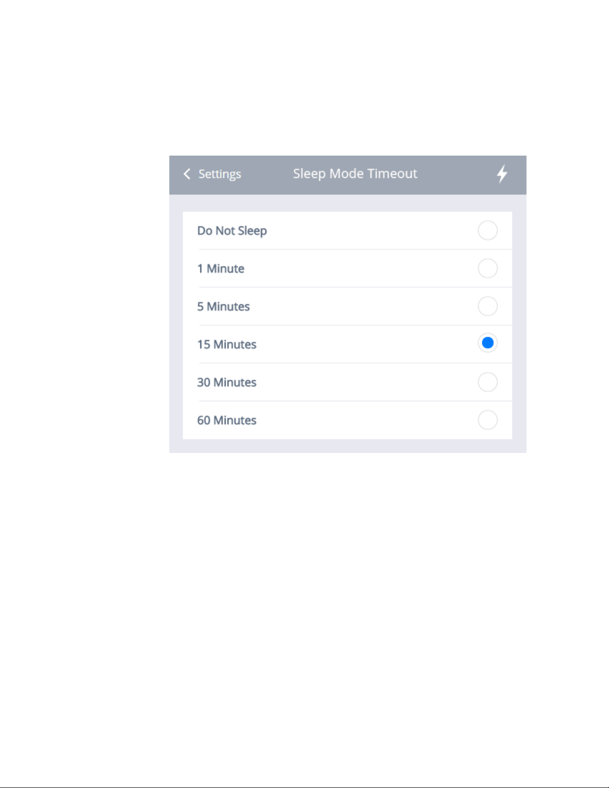
2. The Sleep Mode Timeout’ Section will appear, as shown below. You may
choose between Do Not Sleep, 1 Minute, 5 Minutes, 15 Minutes, 30 Min-
utes, or 60 Minutes (15 Minutes is the default setting).
3. Select the desired interval and click on ‘Settings’ to return to the Power
Savings Menu.
4. If the user enables all sleep modes and keeps the default values. The LCD
will black out at 5 minutes. After a total of 20 minutes (5 + 15), the System
will go into sleep mode. After 50 minutes (5+15+30), the unit will autopower off.
100 Cirrus LT Plus User Manual v1.2 - Chapter 4
 Loading...