

NCR RealPOS XR6 User Manual
USER GUIDE
NCR RealPOS XR6 (7603)
Release 1.0
B005-0000-2400
Issue A

The product described in this document is a licensed product of NCR Corporation.
NCR is a registered trademark of NCR Corporation. NCR RealPOS is a trademark of NCR Corporation in the United States
and/or other countries. Other product names mentioned in this publication may be trademarks or registered trademarks of their
respective companies and are hereby acknowledged.
The terms HDMI and HDMI High-Definition Multimedia Interface, and the HDMI Logo are trademarks or registered trademarks
of HDMI Licensing LLC in the United States and other countries.
Where creation of derivative works, modifications or copies of this NCR copyrighted documentation is permitted under the terms
and conditions of an agreement you have with NCR, NCR's copyright notice must be included.
It is the policy of NCR Corporation (NCR) to improve products as new technology, components, software, and firmware become
available. NCR, therefore, reserves the right to change specifications without prior notice.
All features, functions, and operations described herein may not be marketed by NCR in all parts of the world. In some instances,
photographs are of equipment prototypes. Therefore, before using this document, consult with your NCR representative or NCR
office for information that is applicable and current.
To maintain the quality of our publications, we need your comments on the accuracy, clarity, organization, and value of this book.
Please use the link below to send your comments.
EMail: FD230036@ncr.com
Copyright © 2015
By NCR Corporation
Duluth, GA U.S.A.
All Rights Reserved
iii
Preface
Audience
This book is written for hardware installer/service personnel, system integrators, and
field engineers.
Notice: This document is NCR proprietary information and is not to be disclosed or
reproduced without consent.
Safety Requirements
The NCR RealPOS XR6 conforms to all applicable legal requirements. To view the
compliance statements see the NCR RealPOS Terminals Safety and Regulatory Statements
(B005-0000-1589).
Caution: The on/off switch is a logic switch only. The AC line voltage primaries are
live at all times when the power cord is connected. Therefore, disconnect the AC power
cord before opening the unit to install features or service this terminal.
Caution: This product does not contain user serviceable parts. Servicing should only
be performed by a qualified service technician.
Fuse Replacement
Warning: For continued protection against risk of fire, replace only with the same
type and ratings of fuse.
Attention: Pour prévenir et vous protéger contre un risque de feu, remplacer la fusible
avec une autre fusible de même type, seulement.
Lithium Battery Warning
Warning: Danger of explosion if battery is incorrectly replaced. Replace only with
the same or equivalent type as recommended by the manufacturer. Discard used
batteries according to the manufacturer's instructions.
Attention: Il y a danger d'explosion s'il y a remplacement incorrect de la batterie.
Remplacer uniquement avec une batterie du même type ou d'un type recommandé par
le constructeur. Mettre au rébut les batteries usagées conformément aux instructions du
fabricant.
Battery Disposal (Switzerland)
Refer to Annex 4.10 of SR814.013 for battery disposal.

iv
IT Power System
This product is suitable for connection to an IT power system with a phase-to-phase
voltage not exceeding 240 V.
Peripheral Usage
This terminal should only be used with peripheral devices that are certified by the
appropriate safety agency for the country of installation (UL, CSA, TUV, VDE) or those
which are recommended by NCR Corporation.
Warning: DO NOT connect or disconnect the transaction printer while the terminal
is connected to AC power. This can result in system or printer damage.
Warning: DO NOT connect or disconnect any serial peripherals while the terminal
is connected to AC power. This can result in system or printer damage.
Grounding Instructions
In the event of a malfunction or breakdown, grounding provides a path of least
resistance for electric current to reduce the risk of electric shock. This product is
equipped with an electric cord having an equipment-grounding conductor and a
grounding plug. The plug must be plugged into a matching outlet that is properly
installed and grounded in accordance with all local codes and ordinances. Do not
modify the plug provided – if it will not fit the outlet, have the proper outlet installed by
a qualified electrician. Improper connection of the equipment-grounding conductor can
result in a risk of electric shock.
The conductor with insulation having an outer surface that is green with or without
yellow stripes is the equipment-grounding conductor.
If repair or replacement of the electric cord or plug is necessary, do not connect the
equipment-grounding conductor to a live terminal. Check with a qualified electrician or
service personnel if the grounding instructions are not completely understood, or if you
are in doubt as to whether the product is properly grounded.
Use only 3-wire extension cords that have 3-prong grounding plugs and 3-pole
receptacles that accept the product’s plug. Repair or replace damaged or worn cords
immediately.
References
• NCR RealPOS XR6 Site Preparation Guide (B005-0000-2401)
• NCR RealPOS XR6 Hardware Service Manual (B005-0000-2402)
• NCR RealPOS XR6 Parts Identification Manual (B005-0000-2403)

Table of Contents
Chapter 1: Product Overview
Introduction 1
Product IDs 1
Configurations 1
Operator Controls 4
Cabinet Security 4
Serial Number/Model Number Label 5
Features 6
Motherboard 6
Storage Media 6
Power Supply 6
Operating Systems 6
v
Graphics 7
Power Management 8
G3 Mechanical Off 8
G2/S5 Soft Off 8
G1 Sleeping 8
G0 Working 8
ACPI Sleep States (S0 - S5) 9
Enabling Wake on LAN 11
Windows 7 11
ACPI Processor C-States 13
Operator Displays 14
NCR 5943 12.1-Inch LCD 14
NCR 5943 15-Inch LCD 15
NCR 5967 12-Inch Touch LCD 16
NCR 5967 15-Inch Touch LCD 17
NCR 5954 15-Inch DynaKey 18
NCR 5982 6.5-Inch LCD Display 19
NCR 5976 2x20 LCD Customer Display 20
Keyboards 22
NCR 5932 Keyboards 22

vi
Keyboard Power 22
NCR 5932-222x 64-Key PS/2 POS Keyboard 23
NCR 5932-5xxx USB Alphanumeric Big Ticket Keyboard 26
Features 26
NCR 5932-65xx PS/2 Programmable POS Keyboard 27
NCR 5932-66xx USB Programmable POS Keyboard 28
Printers 29
NCR 7167 Printer 29
NCR 7168 Printer 30
NCR RealPOS 7197 Printer 31
NCR 7198 Printer 32
Chapter 2: Hardware Installation
Installation Restrictions 33
Chapter 2: Diagnostics
LED Diagnostic Indicators 34
Installing the Terminal 38
Installing the Keyboard and Mouse 39
Connecting AC Power 41
Disconnecting the Power Cable 42
PS/2 Cable Connection 43
Installing a Transaction Printer 44
USB Installation 44
RS-232 Installation 45
Installing a Remote Display 46
NCR 5943/5967 12-inch LCD Cable Connections 48
NCR 5943/5967 15-inch LCD Cable Connections 50
NCR 5954 USB DynaKey Cable Connections 52
Installing an NCR 5982 6.5-Inch LCD 54
Installing a 5975/5976 Customer Display 58
RS-232 Interface 60
USB Interface 61
Installing a Secondary Display (Dual Display) 62
Setting the Display Mode 63
Installing a Cash Drawer 66
Installing Two Cash Drawers 67
Replacing the Hard Disk Drive 68

Chapter 3: Disk Image Backup and Recovery Tool
Introduction 71
Running the Recovery Tool 72
Starting the Recovery Tool 72
Main Screen 73
Check and Repair Disk 73
Save or Load Image 73
Change Settings 73
Shutdown or Reboot 73
System Information 73
Save Or Load Image 74
Saving An Image 75
Loading An Image 78
Change Settings 83
vii
Change Network Settings 84
Change Password 85
Replace Recovery Image 86
Change Language 87
Creating a Disk Image 88
Chapter 4: BIOS Setup
Entering Setup 89
How to Select Menu Options 89
Restoring Factory Settings 89
BIOS Default Values 90
Main Menu 90
Advanced Menu 90
Chipset 96
Boot Menu 99
Chapter 5: Initial Terminal Imaging
Introduction 101
Imaging Procedure 101
Chapter 5: BIOS Setup
Entering Setup 102
How to Select Menu Options 102

viii
Restoring Factory Settings 102
BIOS Default Values 103
Main Menu 103
Advanced Menu 103
Chipset 109
Boot Menu 112
Chapter 6: BIOS Updating Procedure
Introduction 113
Prerequisites 113
Creating the Bootable Media 114
Creating a Bootable CD 114
Creating a Bootable USB Memory Drive 114
BIOS Updating Procedures 115
Chapter 7: Maintenance
Cabinet Cleaning Procedures 117
Touch Screen Cleaning Procedures 117
MSR Cleaning Procedures 117
MSR Cleaning and Treatment Cards 117
MSR Treatment Card 118
Cleaning/Treatment Frequency 118
Appendix A: Powered Serial Port Settings
Revision Record
Issue Date Remarks
Aug 2015 First Issue
A

Chapter 1: Product Overview
Introduction
The NCR RealPOS XR6 (also known as NCR 7603) is a compact POS solution that
combines the reliability and security of a retail-hardened POS terminal with the
performance and flexibility of industry-standard PC technology. With an open
architecture and Intel® processor, the NCR RealPOS XR6 supports the latest POS
applications for Windows® to help you service your customers quickly and efficiently.
And, it all fits in a small footprint that helps conserve valuable space at the Checkstand.
To complete your POS solution, choose from NCR's extensive line of peripherals,
including printers, displays, keyboards and scanners. The NCR RealPOS XR6 enables
you to protect your investment in legacy serial devices or choose from the growing list
of USB peripherals. The powered peripheral ports and 24V printer interface simplify
cable management and reduce potential points of failure.
Product IDs
Configurations
The NCR RealPOS XR6 is an affordable, retail-ready POS solution that provides
outstanding value for any size retailer. It supports a broad range of certified NCR
peripherals and applications. The RealPOS XR6 features the smallest form factor in its
class and offers versatile configuration and mounting options.
Choose from NCR's extensive line of peripherals, including printers, displays,
keyboards and scanners. The RealPOS XR6 provides flexible connectivity options to
power peripherals as well as dual display support for customer-facing advertising and
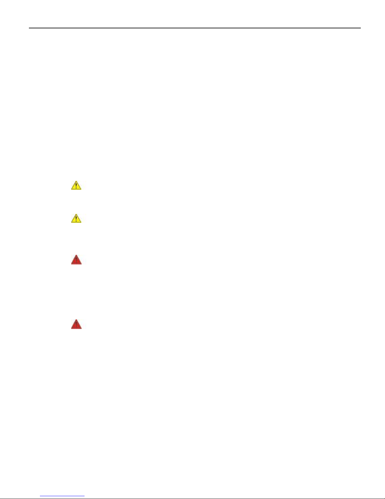
messaging. The system can be configured modularly or stacked on an NCR 2181 Cash
Drawer in an integrated fashion.
Major Model CPU
7603-1100 RealPOS XR6, Intel Celeron G1820TE, Dual Core 2.3 GHz,
4 GB DDR3, Diskless
7603-1300 RealPOS XR6, Intel Core-i3 4350T Dual Core 3.1 GHz,
4 GB DDR3, Diskless
7603-1500 RealPOS XR6, Intel Core-i5 4590T Dual Core 3.0 GHz,
4 GB DDR3, Diskless
1-2 Product Overview
Modular Configuration
Stacked Configuration
Product Overview 1-3
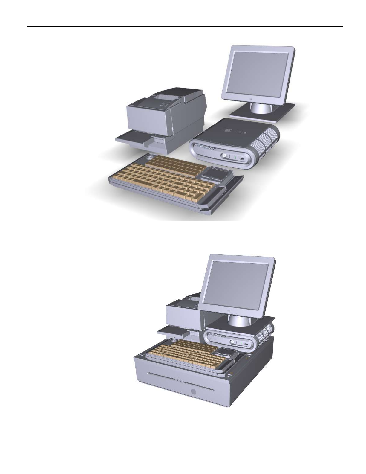
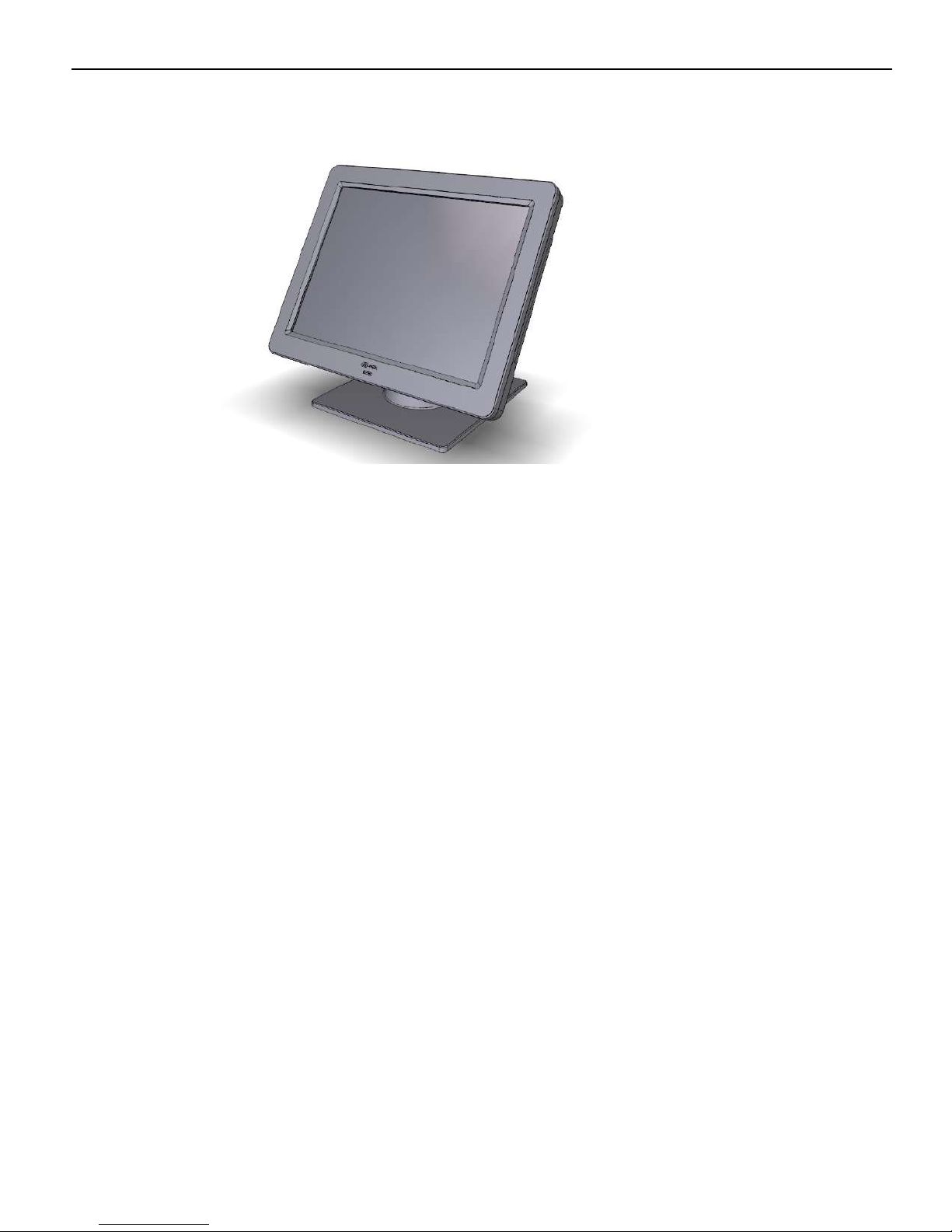
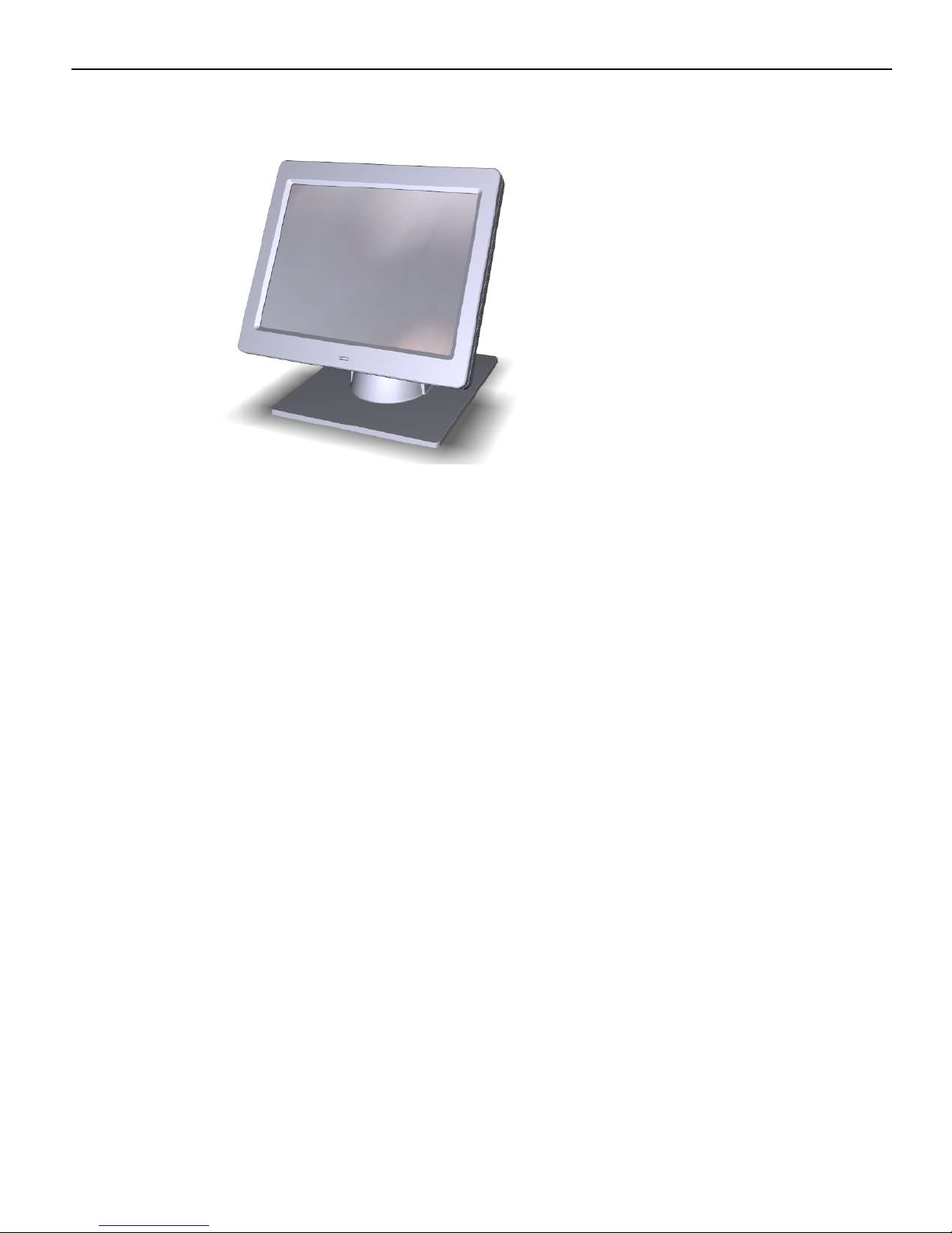
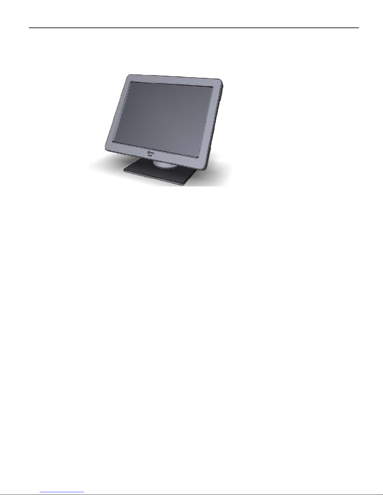
An optional stand is available to mount the terminal vertically.
Vertical Stand Configuration
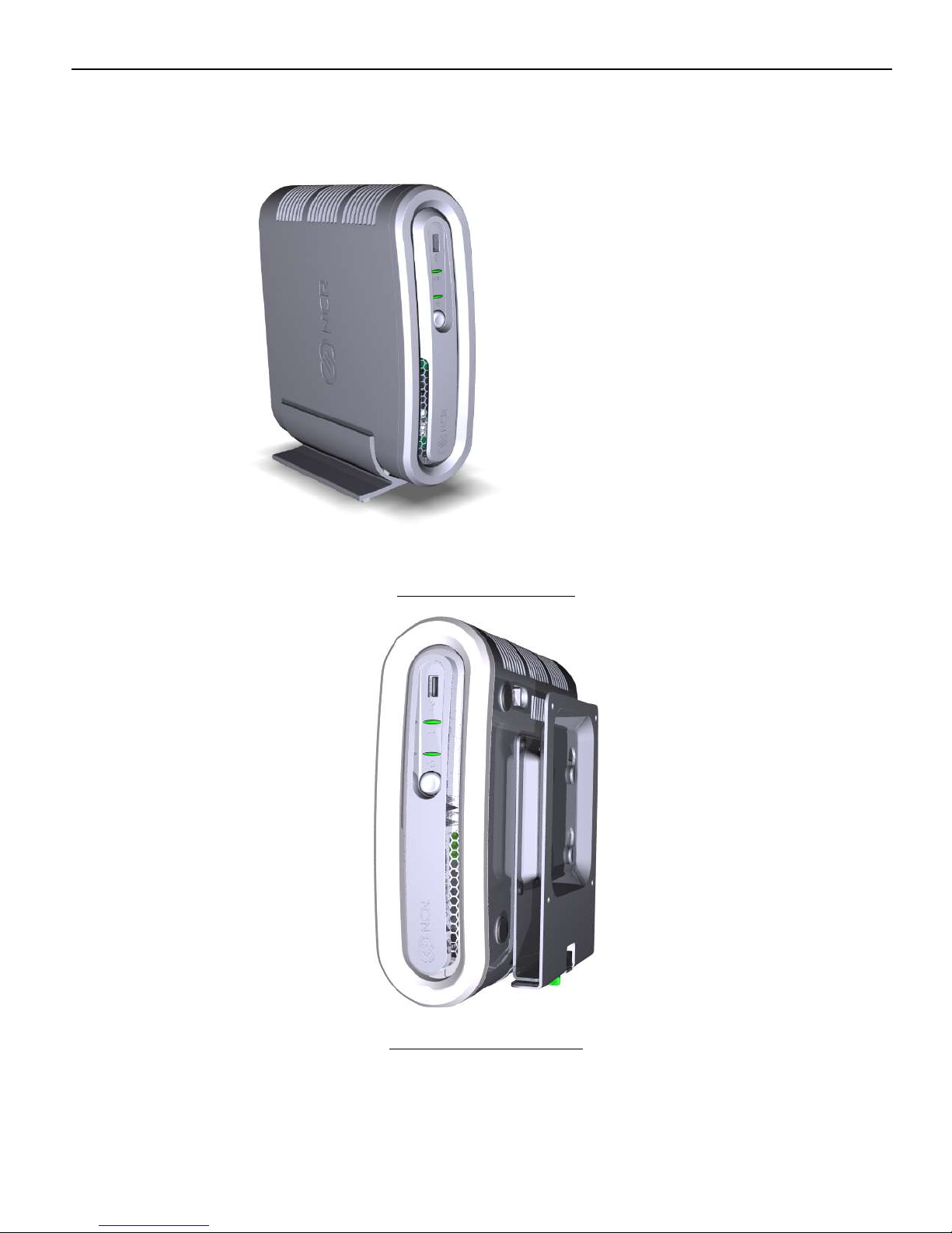
Flush Wall Mount (7409-K502)

1-4 Product Overview
Operator Controls
LED Diagnostic Indicators on page 34.Diagnostics on page 34. for more information about
the LED Diagnostic Indicators.
Cabinet Security
The 7603 has easy access to the internal components. However, the case can be secured
to a fixed object (desk, pole, etc) by attaching a standard Kensington lock to the Security
Hasp. In addition a small padlock can be attached to the hasp to prevent the unit from
being opened.

Product Overview 1-5
Serial Number/Model Number Label
The serial number and model number are included on the Certification Label located on
bottom of the terminal. A Microsoft Certificate of Authenticity (COA) label is included if
the terminal is ordered and shipped with a pre-installed Microsoft Operating System.
There are two types of Microsoft COA stickers. Depending on the Microsoft Operating
System ordered the label is located on either the Bottom Cover for Windows 7 or next to
the Certification Label for SLEPOS, POSReady 2009, and POSReady 7.

1-6 Product Overview
Features
Motherboard
• Intel's Haswell Chipset
• Up to 8GB DDR3 Memory, 1333 MHz, 2 Memory Sockets
• Serial ATA (SATA) Hard Drive Interface
• High-speed Gigabit Ethernet
• Four Powered Serial ports
• HDMI Connector
• Display Port Connector
• DVI-D connector
• VGA connector
• PS/2 Connector supporting Mouse and Keyboard through a Y-cable
• USB Ports
Storage Media
Power Supply
• One 12V USB+Power port
• Two Type-A USB Connectors
• One 24V USB+Power port
Note: For security purposes individual USB ports can be disabled in the BIOS at:
Chipset >> PCH-IO Configuration >> SB USB Configuration
• Dual cash drawer support from one connector using Y-cable
• Audio Line Out (Amplified)
• Three 12V USB+Power ports on a USB Daughter Card (Optional)
• DC Power Jack for Power Brick
• Image Recovery Button
• 2.5" SATA Hard Drive (Feature)
• 2.5" SATA Solid State Drive (Feature)
• 150W Output power
• Switching Power Supply, External 24V Adapter
• MEPS Level V mark (efficiency 87% minimum)
• Supports 24V retail printers at 55W maximum when connected to 7603
Operating Systems
• Windows 7 Professional (32/64-Bit)
• Windows Embedded POSReady 7 (32/64-Bit)

Product Overview 1-7
• Windows Embedded POSReady 2009
• SUSE Linux SLEPOS11 SP2
Graphics
The Motherboard has integrated graphics on board. PCI Express x16 graphics adapters.
are not supported.
Output ports
Dual independent displays in Concurrent (Clone) and Extended Desktop modes are
supported by the 7603.
HDMI
Digital interface for monitor or HDTV driven from Digital Port B on the CPU using a
Standard vertical Type A HDMI connector on rear IO.
Note: An adapter cable can be used to support DVI.
Display Port
Display Port driven from Digital Port C on the CPU using a standard vertical Display
Port connector on rear I/O.
VGA
Analog display signals for legacy monitors. Standard DB-15 connector on rear IO.

1-8 Product Overview
Power Management
The BIOS supports the Advanced Configuration and Power Management Interface
(ACPI) 3.0 specification. A key feature of ACPI is that the operating system, not the
BIOS, configures and implements power management. The 7603 terminal supports the
Global system power states defined by ACPI:
G3 Mechanical Off
A computer state that is entered and left by a mechanical means.
Example: Turning off the system's power through the movement of a large red
switch.
Various government agencies and countries require this operating mode. It is implied by
the entry of this off state through a mechanical means that no electrical current is
running through the circuitry and that it can be worked on without damaging the
hardware or endangering service personnel. The OS must be restarted to return to the
Working state. No hardware context is retained. Except for the real-time clock, power
consumption is zero.
G2/S5 Soft Off
G1 Sleeping
G0 Working
A computer state where the computer consumes a minimal amount of power. No user
mode or system mode code is run. This state requires a large latency in order to return
to the Working state. The system's context will not be preserved by the hardware. The
system must be restarted to return to the Working state. It is not safe to disassemble the
machine in this state.
A computer state where the computer consumes a small amount of power, user mode
threads are not being executed, and the system appears to be off (from an end user's
perspective, the display is off, and so on). Latency for returning to the Working state
varies on the wake environment selected prior to entry of this state (for example,
whether the system should answer phone calls). Work can be resumed without
rebooting the OS because large elements of system context are saved by the hardware
and the rest by system software. It is not safe to disassemble the machine in this state.
A computer state where the system dispatches user mode (application) threads and they
execute. In this state, peripheral devices (peripherals) are having their power state
changed dynamically. The user can select, through some UI, various
performance/power characteristics of the system to have the software optimize for
performance or battery life. The system responds to external events in real time. It is not
safe to disassemble the machine in this state.

Product Overview 1-9
ACPI Sleep States (S0 - S5)
Under the G1 sleeping state ACPI defines levels of system sleep state support. The 7603
supports the following sleeping states:
• S0: Normal Powered-On state
• S1 (Standby): The S1 sleeping state is a low wake latency sleeping state. In this state,
no system context is lost (CPU or chip set) and hardware maintains all system
contexts.
Note: The 7603 does not support S1 state. Turning off the backlight and hard drives
provides the equivalent power savings (due to Intel's processor C-states feature) at
nearly zero latency.
• S2: Not supported
• S3 (Suspend to Ram): The S3 sleeping state is a low wake latency sleeping state. This
state is similar to the S1 sleeping state except that the CPU and system cache context
is lost (the OS is responsible for maintaining the caches and CPU context). Control
starts from the processor's reset vector after the wake event. In NCR systems, during
S3, power is only provided to the on-board USB ports.
Note: When the terminal resumes from an S3 state, all the USB devices re-
enumerate. This causes speaker tones as if they were disconnected and then
reconnected. This does not present a problem and the USB devices will continue to
operate correctly.
Requirements for S3 support:
• O/S must be built on a system with S3 enabled in the BIOS
• Some peripherals may not be S3 capable, which can prevent the system from
entering S3 state.
• "S4 (Suspend to Disk): The S4 state is the lowest power, longest wake latency
sleeping state supported by ACPI. In order to reduce power to a minimum, it is
assumed that the hardware platform has powered off all devices. Platform context is
maintained.
Requirements for S4 support:
• O/S must be built on a system with S3 enabled in the BIOS
• Some peripherals may not be S4 capable, which can prevent the system from
entering S4 state.
Reference the ACPI Specification for details.
Peripherals: ACPI defines power states for peripherals which are separate from the
system power state. The device power states range from D0 (fully-on) to D3 (off) It is
the responsibility of the driver developer for each peripheral to define and support
the available power states.
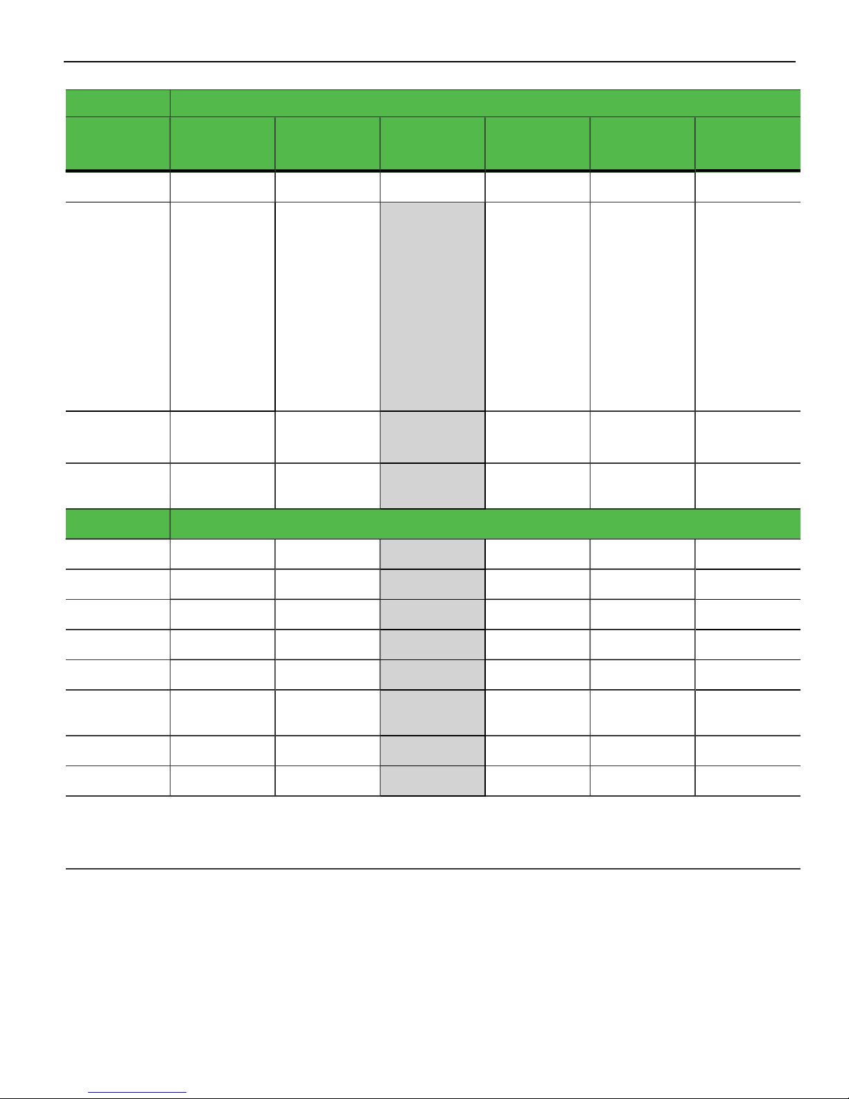
1-10 Product Overview
Power State
Supported
Description
Power Supply
Status
Power
Consumption*
S0Working S1Standby S2
**S3 Suspend
to RAM
S4Hibernate **S5Soft Off
Y Y N Y Y Y
Fully
Functional
On On Powered
• Video Back
Light Off
• HDD Off
• Cache
Flush
• Memory in
Slow
Refresh
• CPU Halted
• Video Back
Light Off
• HDD Off
• Cache
Flush
• Memory in
Slow
Refresh
• CPU Halted
Down**
• Video Back
Light Off
• HDD Off
• Cache
Flush
• Memory in
Slow
Refresh
• CPU Halted
Powered
Down**
OFF
Powered
Down**
37 24 2 1 <1
Wake Options
Power Switch
PS/2 Keyboard
PS/2 Mouse
USB Keyboard
USB Mouse
LAN (magic
packet)
RTC Alarm
Serial Port (RI)
Note: Power consumption based on the following configuration with no peripherals Intel Celeron 900, 512MB DIMM, HDD
*Maintains small voltage to support wake circuits)
**The external power supply is ON while in S3-S5. The motherboard shuts down all power circuits except for a small voltage to
support wake circuits. Power to the 24V USB printer port and the Cash drawer is also disconnected while in S3-S5
N/A Y Y Y Y
N/A Y Y N N
N/A Y Y N N
N/A Y Per O/S N N
N/A Y Per O/S N N
N/A Y Y Y Y
N/A Y Y Y Y
N/A Y N N N
Product Overview 1-11
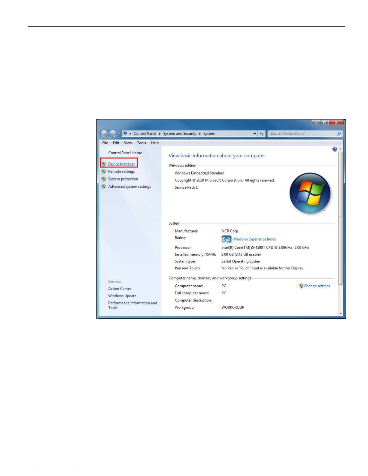
Enabling Wake on LAN
In order for Wake on LAN to function the Network driver must be enabled (factory
default). The procedure for enabling the driver depends on which operating system you
are using.
Windows 7
1. Computer >> System Propertiestab >> Device Manager
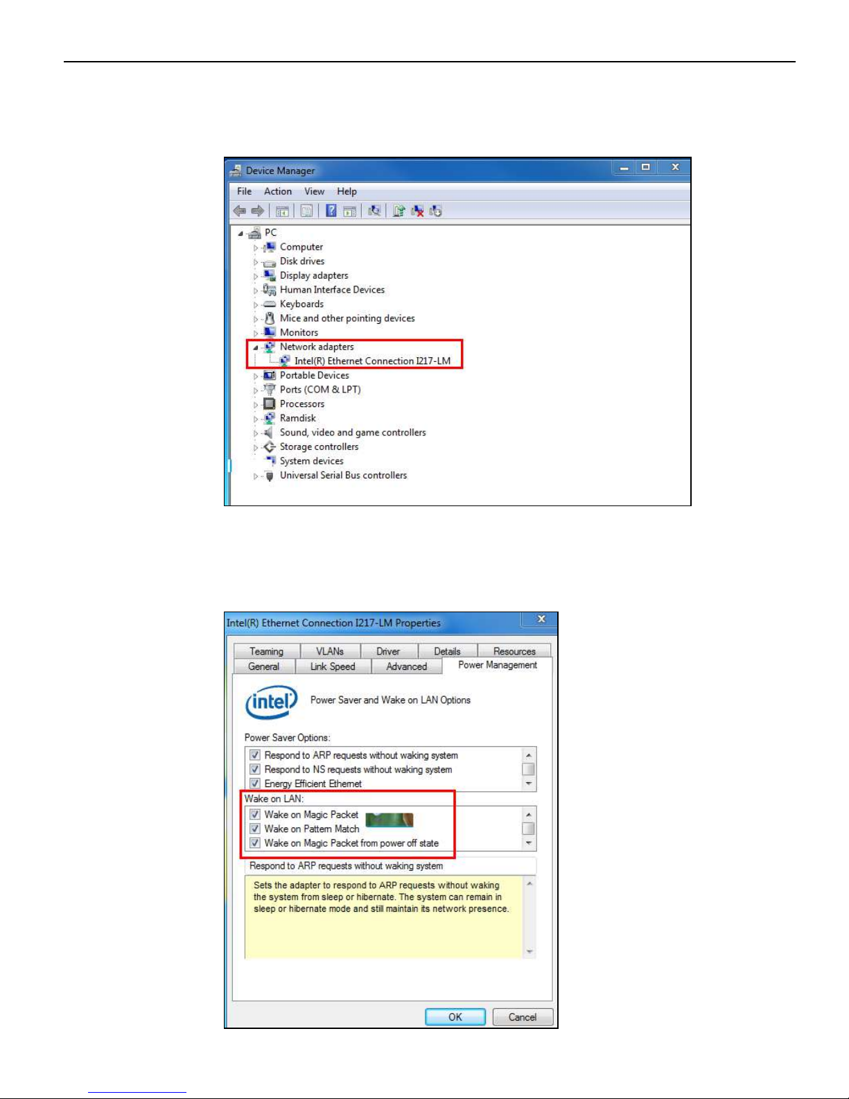
1-12 Product Overview
2. Select Network adapters.
3. Right-click Intel(R) Ethernet Connection J217-LM >> Properties.
4. Under the Power Management tab, Wake on Magic Packet and Wake on Pattern Match
and Wake on Magic Packet from power off state option boxes should be checked. Select
OK after making any changes.

Product Overview 1-13
ACPI Processor C-States
ACPI defines the power state of system processors while in the G0 working state as
being either active (executing) or sleeping (not executing). Processor power states are
designated C0, C1, C2, C3, …Cn.
The C0 power state is an active power state where the CPU executes instructions. The C1
through Cn power states are processor sleeping states where the processor consumes
less power and dissipates less heat than leaving the processor in the C0 state.
While in a sleeping state, the processor does not execute any instructions. Each
processor sleeping state has a latency associated with entering and exiting that
corresponds to the power savings. In general, the longer the entry/exit latency, the
greater the power savings when in the state.
To conserve power, OSPM places the processor into one of its supported sleeping states
when idle. While in the C0 state, ACPI allows the performance of the processor to be
altered through a defined "throttling" process and through transitions into multiple
performance states (P-states).
Note: The 7603 Atom D2550 Processor supports C0 and C1 states. Support of deeper
sleep states is not required due to its inherently low power consumption.
1-14 Product Overview
Operator Displays
NCR 5943 12.1-Inch LCD
The NCR 5943 LCD is an LED backlit LCD display (XGA, 1024 x 768). The display is
powered by the terminal from a +12V USB Plus Power port. The remote mount must be
ordered separately.
• LCD panel
• Display Size: 12.1-inch
• LCD Technology: TFT, Pixel Configuration: RGBW Rectangle
• LCD Backlit Technology: LED-Backlit
• Native Format: 1024x768, 262,144 colors: (RGB 6bits) color depth or greater
• Viewing Direction: 12 o’clock
• 50K hour minimum backlight ½ life at rated luminance
• VESA & Industry Standards
• Retail hardened display
• Dual video inputs, standard analog (DB15) video interface and DVI interface
• No OSD controls - all SW driven
• Flexible cable length options (compatibility with NCR 1m & 4m external cables)
• Clean (hidden) cable management
• ISO 3-Track/JIS 2-Track MSR (Optional
Product Overview 1-15
NCR 5943 15-Inch LCD
The NCR 5943 LCD is an LED backlit LCD display (XGA, 1024 x 768). The display is
powered by the terminal from a +12V USB Plus Power port. The remote mount must be
ordered separately.
• LCD panel
• Display Size: 15-inch
• LCD Technology: TFT, Pixel Configuration: RGBW Rectangle
• LCD Backlit Technology: LED-Backlit
• Native Format: 1024x768, 262,144 colors: (RGB 6bits) color depth or greater
• Viewing Direction: 12 o’clock
• 50K hour minimum backlight ½ life at rated luminance
• Standard VGA and DVI video inputs
• VESA 75 Mounting Compliance
• Retail hardened display
• Standard VGA and DVI video inputs
• No OSD controls - all SW driven
• ISO 3-Track/JIS 2-Track MSR (Optional
• Integrated speakers
1-16 Product Overview
NCR 5967 12-Inch Touch LCD
The NCR 5967 Touch LCD is an LED backlit LCD display (XGA, 1024 x 768) with
capacitive touch screen. The display is powered by the terminal from a +12V USB Plus
Power port. The remote mount must be ordered separately.
• LCD panel
• Display Size: 12.1”
• LCD Technology: TFT, Pixel Configuration: RGBW Rectangle
• LCD Backlit Technology : LED-Backlit
• Native Format: 1024x768, 262,144 colors: (RGB 6bits) color depth or greater
• Display Mode: Normally white
• Viewing Direction: 12 o’clock
• 370 cd/m2 (typ), 300 cd/m2 (min) luminance to user
• 50K hour minimum backlight ½ life at rated luminance
• VESA & Industry Standards
• Spill proof and sealed
• Dual video inputs, standard analog (DB15) video interface and DVI interface.
• LCD LED Backlight is controllable using soft DDC/CI UTILILTY at full or reduced
brightness (no physical DDC/CI UTILILTY buttons)
• ISO 3-Track/JIS 2-Track MSR (Optional)
• USB Port
Product Overview 1-17
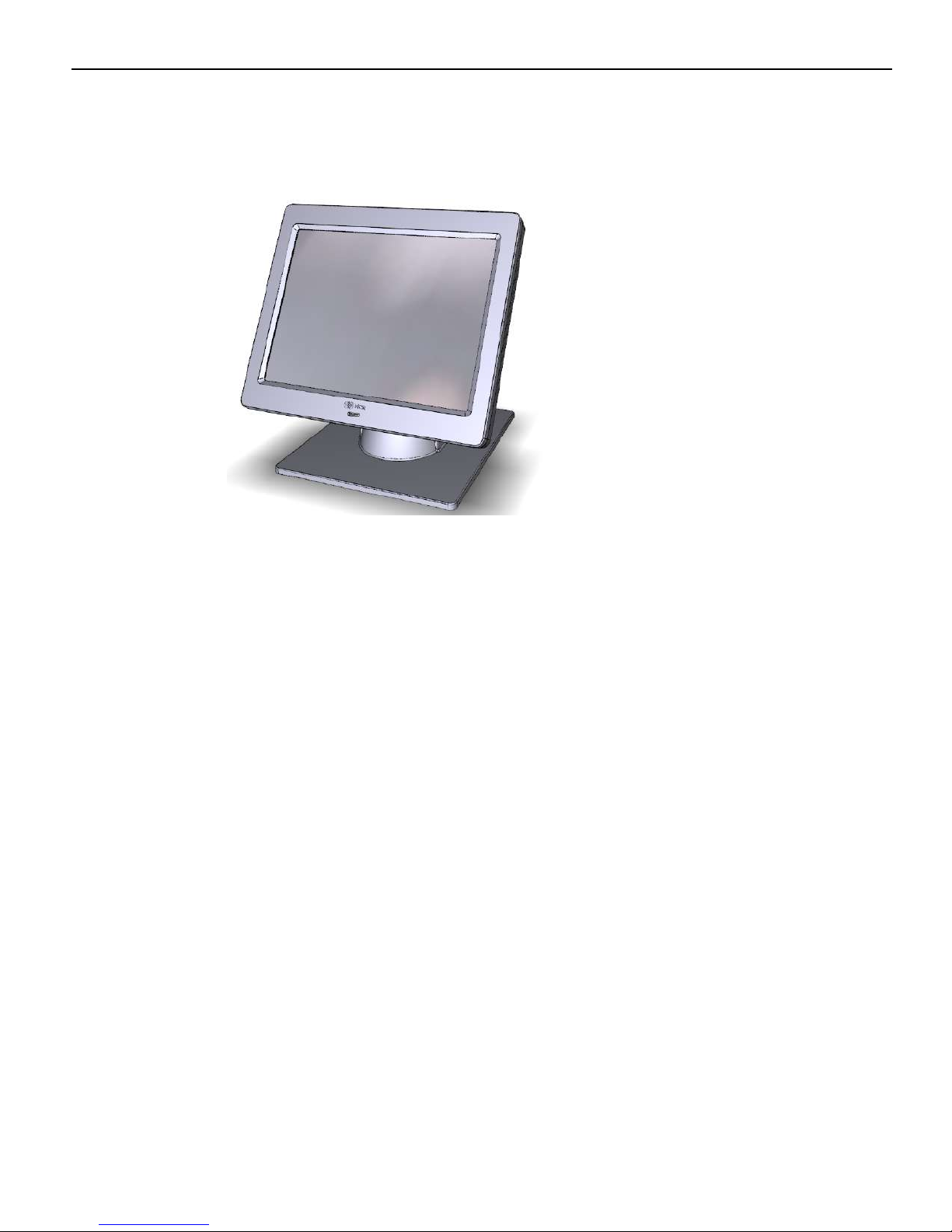
NCR 5967 15-Inch Touch LCD
The NCR 5967 Touch LCD is an LED backlit LCD display (XGA, 1024 x 768) with
capacitive touch screen. The display is powered by the terminal from a +12V USB Plus
Power port. The remote mount must be ordered separately.
• LCD panel
• Display Size: 15-inch
• LCD Technology: TFT, Pixel Configuration: RGBW Rectangle
• LCD Backlit Technology: LED-Backlit
• Native Format: 1024x768, 262,144 colors: (RGB 6bits) color depth or greater
• 50K hour minimum backlight ½ life at rated luminance
• Touch Sensor; Capacitive Touch, USB I/F
• Standard VGA and DVI video inputs
• VESA 75 Mounting Compliance
• Retail hardened display
• Standard VGA and DVI video inputs
• No OSD controls - all SW driven
• ISO 3-Track/JIS 2-Track MSR (Optional
• Integrated speakers
• USB Port

1-18 Product Overview
NCR 5954 15-Inch DynaKey
The NCR RealPOS 5954 USB DynaKey is a Point-of-Sale (POS) keypad with a built-in 15inch flat panel Liquid Crystal Display (LCD). Unique to the DynaKey is a set of ATMstyle keys (DynaKeys), which are located beside the display. The functions of these keys
change depending on the software application appearing on the LCD.
Note: USB DynaKey requires Windows XP/XPe.
The combined display and keypad is designed to reduce operator training time, simplify
complex POS transactions and improve associate/cashier productivity. Combined with
the appropriate applications software, the DynaKey can virtually eliminate the need for
an operator to memorize function key locations and sequence.
The USB DynaKey interfaces with the host terminal via two cables.
• Digital Video Interface (DVI) cable for video
• Powered Universal Serial Bus (USB) for data and power
The DynaKey is available in two color schemes.
• Light Gray (G11)
• Charcoal Gray (CG1)

Product Overview 1-19
NCR 5982 6.5-Inch LCD Display
The 5982 LCD Display is a terminal-powered color 6.5 Inch VGA LCD.
Features
• 5-inch VGA Monochrome LCD (640 x 480 VGA)
• Contrast Control
• LED Back Light
• Keyboard Mount
• Low-Post Table-Top Mount
• VGA Video
• Powered by 12 V USB Cable

1-20 Product Overview
NCR 5976 2x20 LCD Customer Display
The NCR RealPOS 5976-1xxx Customer Display is a 2-line x 20-character LED backlit
Liquid Crystal Display (LCD), which can display any downloadable codepage of single
byte characters. It supports both RS-232 and USB interfaces.
• 5976-1100 2x20 LCD (G11)
• 5976-1200 2X20 LCD (CG1)
There are four post options, available in 4 inch increments.
Features
• 2x20 Character Liquid Crystal Display (LCD)
• LCD Technology: Advance Black Nematic (ABN)
• True white on black LED display
• Sealed against dust and spill resistant
• High-Contrast/High Bright
• Low Power Consumption
• 7x9 pixel characters
• Character height
• Minimum - 9.5mm
• Maximum - 10.5mm
• LED backlight: 50K hour minimum backlight life at ½ rated luminance
• Luminance: 200-500 nits
• Three pre-loaded Code pages
• Up to 19 downloadable Code pages
• MB Flashable memory

Product Overview 1-21
Power Supply
• Universal Power Supply (12V, 12W output)
• 8 pin Molex Connector
EIA-232 or USB 2.0 I/F support
• The components for both interfaces are populated on a single printed circuit
board. Both interfaces are active, though only one interface can be physically
connected at a time. The display communicates via the interface that is
connected to it.
Mounting Options
• Table Mount, 4-in. Post
• Table Mount, 8-in. Post
• Table Mount, 12-in. Post
• Table Mount, 16-in. Post
• Integrated Mount for NCR 7456, 7457, 7458
Character Sets
• Support for 19 character sets
• 3 Character sets in base unit
• Code Page 858 (International)
• Katakana
• Code Page 866 (Cyrillic)
• 2 MB Flash Memory for support of up to 16 additional character sets

1-22 Product Overview
Keyboards
NCR 5932 Keyboards
The NCR 5932 Keyboards are intended for harsh retail environments and contain an
internal membrane to protect against objects such as paper clips, staple wires, pins, and
so forth, from falling between the keys and damaging the electronics. This technology
improves overall reliability not typically found in standard PC keyboards or many retail
keyboards.
The RealPOS XR6 supports the following NCR 5932 Keyboards:
• NCR 5932-222x 64-Key PS/2 POS Keyboard
• NCR 5932-5xxx USB Big Ticket Keyboard
• NCR 5932-65xx PS/2 Compact Keyboard
• NCR 5932-66xx USB Compact Keyboard
Keyboard Power
The RealPOS XR6 supplies power to the PS/2 keyboard even when in the OFF state. This
is for configurations that require the terminal to turn on when a key is pressed. Most
NCR PS/2 keyboards have a Power ON LED which stays illuminated, indicating power
is present in the keyboard. Pressing a key may also cause tones to be sounded, but
unless the terminal is configured to power up when a key is press, nothing happens
 Loading...