

NCR RealPOS 7458 Hardware Service

NCR RealPOS 7458
Release 1.0
Hardware Service
B005-0000-1442
Issue A

The product described in this book is a licensed product of NCR Corporation.
NCR is a registered trademark of NCR Corporation.
NCR RealPOS, NCR RealPrice, NCR RealScan, NCR EasyPoint and NCR FastLane are either registered
trademarks or trademarks of NCR Corporation in the United States and/or other countries.
It is the policy of NCR Corporation (NCR) to improve products as new technology, components, software,
and firmware become available. NCR, therefore, reserves the right to change specifications without prior
notice.
All features, functions, and operations described herein may not be marketed by NCR in all parts of the
world. In some instances, photographs are of equipment prototypes. Therefore, before using this document,
consult with your NCR representative or NCR office for information that is applicable and current.
To maintain the quality of our publications, we need your comments on the accuracy, clarity, organization,
and value of this book.
Address correspondence to:
Manager, Information Products
NCR Corporation
2651 Satellite Blvd.
Duluth, GA 30096
Copyright © 2003
By NCR Corporation
Dayton, Ohio U.S.A.
All Rights Reserved

i
Preface
Audience
This book is written for hardware installer/service personnel, system
integrators, and field engineers.
Notice: This document is NCR proprietary information and is not to
be disclosed or reproduced without consent.
Safety Warnings
Servicing
Caution: This product does not contain user serviceable parts.
Servicing should only be performed by a qualified service technician.
Fuse Replacement
Caution: For continued protection against risk of fire, replace only
with the same type and ratings of fuse.
Attention: Pour prévenir et vous protéger contre un risque de feu,
remplacer la fusible avec une autre fusible de même type, seulement.
Power Supply Cord Used as Disconnect Means
Caution: The power supply cord is used as the main disconnect
device. Ensure that the socket outlet is located/installed near the
equipment and is easily accessible.
Attention: Le cordon d'alimentation est utilisé comme interrupteur
général. La prise de courant doit être située ou installée å proximité du
matériel et être facile d'accés.

ii
Lithium Battery Warning
Caution: Danger of explosion if battery is incorrectly replaced.
Replace only with the same or equivalent type as recommended by the
manufacturer. The battery is battery is recyclable. At the end of its
useful life, under various state and local laws it may be illegal to
dispose of this battery into the municipal waste. Contact officials for
recycling options or proper disposal.
Attention: Il y a danger d'explosion s'il y a remplacement incorrect de
la batterie. Remplacer uniquement avec une batterie du même type ou
d'un type recommandé par le constructeur. Mettre au rébut les
batteries usagées conformément aux instructions du fabricant.
Battery Disposal (Switzerland)
Refer to Annex 4.10 of SR814.013 for battery disposal.
IT Power System
This product is suitable for connection to an IT power system with a
phase-to-phase voltage not exceeding 240 V.
Peripheral Usage
This terminal should only be used with peripheral devices that are
certified by the appropriate safety agency for the country of installation
(UL, CSA, TUV, VDE) or those which are recommended by NCR
Corporation.
Caution: DO NOT connect or disconnect a printer, keyboard, or any
other terminal-powered peripheral while the terminal is powered on.
Doing so may result in peripheral or system damage.
Environmental Consciousness
NCR is demonstrating its concern for the environment by designing an
intelligent power management system into this terminal that operates
efficiently whether the system is in a stand-alone or network
environment.

iii
Grounding Instructions
In the event of a malfunction or breakdown, grounding provides a
path of least resistance for electric current to reduce the risk of electric
shock. This product is equipped with an electric cord having an
equipment-grounding conductor and a grounding plug. The plug must
be plugged into a matching outlet that is properly installed and
grounded in accordance with all local codes and ordinances. Do not
modify the plug provided – if it will not fit the outlet, have the proper
outlet installed by a qualified electrician. Improper connection of the
equipment-grounding conductor can result in a risk of electric shock.
The conductor with insulation having an outer surface that is green
with or without yellow stripes is the equipment-grounding conductor.
If repair or replacement of the electric cord or plug is necessary, do not
connect the equipment-grounding conductor to a live terminal. Check
with a qualified electrician or service personnel if the grounding
instructions are not completely understood, or if you are in doubt as to
whether the product is properly grounded.
Use only 3-wire extension cords that have 3-prong grounding plugs
and 3-pole receptacles that accept the product’s plug. Repair or replace
damaged or worn cords immediately.

iv
References
• NCR RealPOS 7458 Hardware User’s Guide (B005-0000-1440)
• NCR RealPOS 7458 Site Preparation (B005-0000-1441)
• NCR RealPOS 7458 Parts Identification Manual (B005-0000-1443)
• NCR 5932 USB Keyboard User’s Guide (B005-0000-1395)
• NCR 5932 Wedge Keyboard User’s Guide (BD20-1369-A)
• NCR 5942 12.1-Inch LCD Monitor User’s Guide (B005-0000-1394)
• NCR 5953 12.1-Inch DynaKey User’s Guide (B005-0000-1161)
• NCR 5952 Wedge DynaKey User’s Guide (BD20-1370-A)
• NCR 5964 12.1-Inch Touch LCD User’s Guide (B005-0000-1324)
• NCR 5972 2 x 20 Customer Display User’s Guide (B005-0000-1372)
• NCR 5973 International VFD Customer Display User’s Guide
(B005-0000-1162)
• NCR 5982 5-Inch LCD Operator Display User’s Guide (BD20-1443-A)
• NCR 7158 Thermal Receipt and Impact Printer Owner’s Guide
(B005-0000-1112)
• NCR 7167 Two-Station POS Printer Owner’s Guide (B005-0000-1406)
• NCR 7162 Printer Setup & User’s Guide (BD20-1453-A)
• NCR 7194 Thermal Receipt Printer Owner’s Guide (B005-0000-1097)
• NCR 7197 Receipt Printer Owner’s Guide (B005-0000-1409)
• NCR 5945 Electronic Payment Terminal User’s Guide (B005-0000-1104)
• NCR 5992 Signature Capture User’s Guide (B005-0000-1108)

v
Table of Contents
Chapter 1: Product Overview
Introduction ...........................................................................................1-1
Cabinet .............................................................................................1-2
Label Locations...................................................................................... 1-4
Chapter 2: POST Diagnostics
Power-On Self-Test (POST) Errors .....................................................2-1
Recoverable POST Errors .............................................................. 2-2
Error and Beep Codes ....................................................................2-2
Terminal POST Errors.................................................................... 2-6
Test Points and Beep Codes..........................................................2-6
Chapter 3: Hardware Service
Introduction ...........................................................................................3-1
Safety Requirements ......................................................................3-1
Back Panel Cable Connectors.............................................................. 3-3
Electronics Box Disassembly Procedures .......................................... 3-4
Removing the Electronics Tray..................................................... 3-4
Replacing the Electronics Tray................................................. 3-5
Removing the Motherboard.......................................................... 3-6
Replacing the Motherboard.................................................... 3-10
Removing a PCI Adapter Card...................................................3-11
Removing the Power Supply ......................................................3-12
Replacing the Power Supply ..................................................3-13
Removing the Flexible Disk Drive ............................................. 3-13
Replacing the Flexible Disk Drive .........................................3-14
Removing the CD-ROM Drive ...................................................3-14

vi
Replacing the Front Panel Control Board.............................3-16
Replacing the CD-ROM Drive................................................ 3-17
Removing the Hard Disk............................................................. 3-19
Removing the Hard Disk Assembly......................................3-20
Replacing the Hard Disk Assembly ......................................3-20
Removing the Compact Flash..................................................... 3-21
Replacing the Compact Flash................................................. 3-22
Removing the Secondary Hard Disk .........................................3-23
Replacing the Secondary Hard Disk .....................................3-23
Removing the UPS Battery Assembly .......................................3-25
Replacing the UPS Batteries ...................................................3-26
Removing the Fan.........................................................................3-28
Circuit Boards......................................................................................3-29
Processor Board ............................................................................ 3-29
Jumper Settings ........................................................................3-30
Memory Configurations.......................................................... 3-30
Installing Memory Modules ...................................................3-31
Replacing the CPU ................................................................... 3-32
Replacing the Lithium Battery ...............................................3-35
USB Daughter Card......................................................................3-36
Controller Ports ........................................................................ 3-36
3-Slot PCI Riser Card ...................................................................3-39
Ethernet Circuitry.........................................................................3-40
PCI LCD Board (5953-K152) .......................................................3-41
PCI LCD Board (5952-K052) .......................................................3-42
Setting the Panel Select Switch (SW1) ...................................3-42
PCI VGA Video Card (7456-K350)............................................. 3-43
4-Port PCI RS-232 Board (3030-K169)........................................ 3-44
4-Port PCI RS-232 Expansion Card (3212-K170) ...................... 3-45
2-Port PCI RS-232 Expansion Card (3212-K171) ...................... 3-46
Cash Drawer ........................................................................................3-47

vii
Latch Assembly Wiring and Adjustments................................3-47
Power Supply ......................................................................................3-48
AC Input ........................................................................................3-48
DC Outputs ...................................................................................3-48
Maximum Rated Output Power.................................................3-49
UPS ................................................................................................. 3-49
Battery Performance ................................................................ 3-50
Power Supply Cable Pin-Outs.................................................... 3-51
Clearing the Password .......................................................................3-52
Connector Pin-Out Identification ..................................................... 3-53
Primary Power (PS1)....................................................................3-53
USB Daughter Card Power (CN12) ...........................................3-54
USB Daughter Card (CN12)........................................................3-54
Front Panel (CN1)......................................................................... 3-56
Box Fan ......................................................................................3-56
Speaker ......................................................................................3-56
Key .............................................................................................3-56
Power LED ................................................................................3-56
Hard Drive LED ....................................................................... 3-56
ON/OFF ....................................................................................3-57
Link Integrity LED ...................................................................3-57
Reset........................................................................................... 3-57
Back Panel I/O..............................................................................3-57
PS/2 Kybd/Mouse (CN1)....................................................... 3-57
Serial COM1 (CN6) ..................................................................3-58
Serial COM2 (CN5) ..................................................................3-58
Serial COM3 (CN6) ..................................................................3-59
Serial COM4 (CN5) ..................................................................3-59
Serial COM5 UPS (CN9) .........................................................3-60
Video Monitor (CN3)............................................................... 3-60
Ethernet (CN2)..........................................................................3-61

viii
CPU Fan (CN10).......................................................................3-61
LCD Interface (CN4)................................................................3-62
Parallel (CN3) ...........................................................................3-63
IDE-1/IDE-2 (CN17, CN14) ........................................................3-64
Flexible Diskette (CN18).............................................................. 3-65
PCI Riser Card (PCI1) .................................................................. 3-66
PCI Riser Card ..............................................................................3-69
Chapter 4: Cable Routing Guide
Primary IDE Cable................................................................................ 4-1
Secondary IDE Cable............................................................................ 4-3
Flex Diskette Cable ...............................................................................4-4
Front Panel Cables ................................................................................ 4-5
UPS Battery Cables ............................................................................... 4-6
Fan Cable................................................................................................ 4-7
UPS Power Cable ..................................................................................4-8
USB Daughter Card Cable ................................................................... 4-9
Power Supply Harness Clamp..........................................................4-10
Appendix A: Feature Kits
Feature Kit List .....................................................................................A-2
Appendix B: Hardware Specifications
Performance Levels.............................................................................. B-1
Interrupts............................................................................................... B-1

ix
Revision Record
Issue Date Remarks
A Feb 2003 First issue

x
Radio Frequency Interference Statements
Federal Communications Commission (FCC)
Information to User
This equipment has been tested and found to comply with the limits for a Class A
digital device, pursuant to Part 15 of FCC Rules. These limits are designed to provide
reasonable protection against harmful interference when the equipment is operated in
a commercial environment. This equipment generates, uses, and can radiate radio
frequency energy and, if not installed and used in accordance with the instruction
manual, may cause harmful interference to radio communications. Operation of this
equipment in a residential area is likely to cause interference in which case the user
will be required to correct the interference at his own expense.
NCR is not responsible for any radio or television interference caused by unauthorized
modification of this equipment or the substitution or attachment of connecting cables
and equipment other than those specified by NCR. The correction of interference
caused by such unauthorized modification, substitution or attachment will be the
responsibility of the user. The user is cautioned that changes or modifications not
expressly approved by NCR may void the user’s authority to operate the equipment.
Canadian Department of Communications
This Class A digital apparatus complies with Canadian ICES-003.
This digital apparatus does not exceed the Class A limits for radio noise emissions
from digital apparatus set out in the Radio Interference Regulations of the Canadian
Department of Communications.
Cet appareil numérique de la classe A est conforme à la norme NMB-003 du Canada.
Le présent appareil numérique n'émet pas de bruits radioélectriques dépassant les
limites applicables aux appareils numériques de la classe A prescrites dans le
règlement sur le brouillage radioélectriques édicté par le ministrère des
Communications du Canada.

xi
Voluntary Control Council for Interference (VCCI)
International Radio Frequency Interference Statement
Warning: This is a Class A product. In a domestic environment this product may
cause radio interference in which case the user may be required to take adequate
measures.

xii
Declaration of Conformity
Manufacturer's Name
NCR Corporation
Manufacturer's Address
NCR Corporation
Retail Solutions Division – Atlanta
2651 Satellite Boulevard
Duluth, GA 30096-5810
Type of Equipment
Information Technology Equipment
Model Number
Class 7458
Electrical Ratings (Input)
100-120 V/200-240 V, 2.0 A/1.0 A, 50-60 Hz
NCR Corporation, 1700 South Patterson Boulevard, Dayton, OH 45459,
USA, declares that the equipment specified above conforms to the
referenced EU Directives and Harmonized Standards.
EU Directive Harmonized Standard(s)
89/336/EEC (EMC) EN 55022
EN 55024
EN61003-2
EN61003-3
73/23/EEC (Low Voltage) EN 60 950
NCR Corporation
Retail Solutions Division — Atlanta
2651 Satellite Boulevard
Duluth, GA 30096-5810
European Contact:
International IP Counsel
206 Marylebone Road
London, NW1 6LY, England
Chapter 1: Product Overview
Introduction
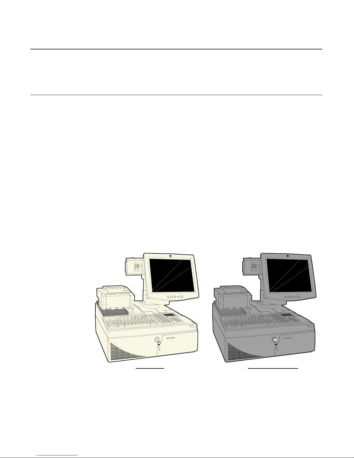
The NCR RealPOS 80 (also referred to as NCR 7458) is a powerful,
retail-hardened point-of-sale terminal targeted for general
merchandise, food and convenience store environments. It provides
exceptional scalability utilizing Intel Celeron and Pentium III
processors to address a range of price/performance levels and
operating system environments. The system offers superior
connectivity for retail, with support for legacy peripheral interfaces
(RS-232, PS/2, Parallel, and VGA), as well as emerging interface
standards such as Powered USB and a DVI video interface.
There are two color schemes available; Beige (G11) and Charcoal
Gray (CG1).
20311c
Beige (G11) Charcoal Gray (CG1)

1-2 Chapter 1: Product Overview
The 7458 is designed with serviceability in mind to reduce costly
downtime. It incorporates the latest in serviceability features including
tool free serviceability. Specifically, the 7458 incorporates:
• Removable hard drive – The terminal utilizes a front-side
removable hard drive that slides easily out of the cabinetry without
the use of any tools, which simplifies replacement.
• Slide out motherboard tray – All internal components are quickly
accessed and replaced without the aid of tools, which significantly
reduces repair times.
• The removable tray results in faster upgrading of memory, hard
drive or other internal components.
Cabinet
The cabinet is optimized to accommodate either modular or integrated
configurations while providing expandability for future needs.
Outstanding flexibility has been designed into the optional integration
tray for use with unified configurations. This integration tray supports
a variety of NCR’s most popular peripheral options.
Internally, the following features are supported:
• 3 PCI slots
• 2 DIMM memory sockets supporting up to 512MB of PC133
SDRAM
• Flex disk drive (standard)
• Dual Hard Disks
• CD ROM drive
• Compact flash memory
• Integrated battery back-up.

Chapter 1: Product Overview 1-3
The following table highlights the standard features and options
available with the RealPOS 80 base Models:
Major Model CPU
7458-1110 Intel 850MHz Celeron, 128MB Memory, Flex Disk, 4
RS-232, 4 Powered USB, Audio/Mic. and US Power
Cord. (G11)
7458-1111 Intel 850MHz Celeron, 128MB Memory, Flex Disk, 4
RS-232, 4 Powered USB, Audio/Mic. and US Power
Cord. (CG1)
7458-1200 Intel 850MHz Celeron, 128MB Memory, Flex Disk, Hard
Disk, 4 RS-232, 4 Powered USB, Audio/Mic. and US
Power Cords (G11)
7458-1201 Intel 850MHz Celeron, 128MB Memory, Flex Disk, Hard
Disk, 4 RS-232, 4 Powered USB, Audio/Mic. and US
Power Cords. (CG1)
7458-2200 Intel 1GHz Pentium III, 256MB Memory, Flex Disk, Hard
Disk, 4 RS-232 4 Powered USB, Audio/Mic. And US
Power Cords. (G11)
7458–2201 Intel 1GHz Pentium III, 256MB Memory, Flex Disk, Hard
Disk, 4 RS-232 4 Powered USB, Audio/Mic. And US
Power Cords. (CG1)
1-4 Chapter 1: Product Overview
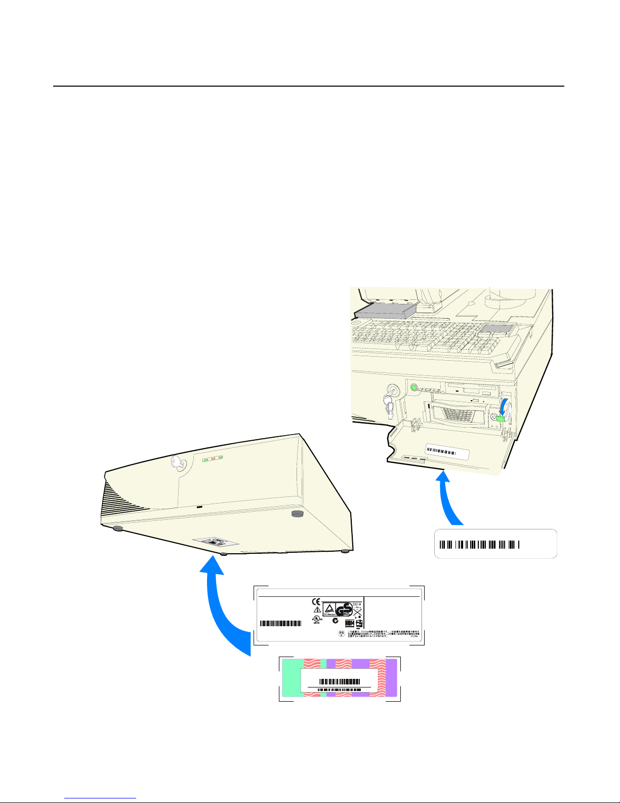
Label Locations
The serial number and model number are included on a label, which is
located on the bottom of the Electronics Box Tray, which can be seen
through a rectangular hole in the bottom of the cabinet. If the terminal
was shipped with an Operating System pre-installed then there is also
a Certificate of Authenticity label.
Note: The serial number is repeated on the inside of the Front Security
Door.
20347
Model No: xxxx
Serial No: 54-xxxxxxxx
Date of Mfg. 04/10/03
Class 7458
NCR Corporation
Atlanta, GA 30096
Made in Singapore
This device complies with Part 15 of the FCC rules.
Operation is subject to the following two conditions:
(1) this device may not cause harmful interference, and
(2) this device must accept any ionterference received,
including interference that may cause indesired operation.
This Class A digital apparatus complies with
Canadian ICES-003
Get Appareli numeriqe de la classe A est
conformo a la normo NMB-003 ju Canada
ACN 000 003 592
NO.437
100-240 Vac 6.0 A 50-60 Hz
I. T. E.
E152553
Windows 2000 Pro Embedded 1-2 CPU
C
e
r
t
i
f
i
c
a
t
e
o
f
A
u
t
h
e
n
t
i
c
i
t
y
H95X7-83WVV-CFCWW-M4MXX7-X6XGM
Product Key:
00019-068-654-234
C
l
a
s
s
:
7
4
5
8
-
2
2
0
1
S
/
N
:
3
6
3
0
9
8
4
5
D
a
t
e
:
2
1
N
o
v
e
m
b
e
r
2
0
0
2
Class:7458-2201
S/N:36309845 Date:21 November 2002

Chapter 2: POST Diagnostics
Power-On Self-Test (POST) Errors
Whenever a recoverable error occurs during POST, the BIOS displays
an error message describing the problem.
If a system boot is incomplete (for example, the system is turned off
while it is going through the POST), then the next time the system is
powered on you may get a message stating that the previous boot was
incomplete. The BIOS will revert to safe values for the chip set, caches,
I/O components, etc. This provides the best possibility of returning to
the Setup routine and to normal functioning, but these values do not
always produce maximum system performance. To achieve maximum
performance after the BIOS has reverted to safe values, re-enter Setup
and select the maximum performance values.
If, for example, the terminal was simply turned off during POST, you
can return to the maximum performance values by simply entering
Setup and exiting or by rebooting.
During POST, you are asked to press <F1> and boot with the default
configuration. If you simply presses <F1> and then do not later return
to Setup, the system will boot; but the external cache will not be
enabled, even though the default configuration will enable the cache.

2-2 Chapter 2: POST Diagnostics
Recoverable POST Errors
Whenever a recoverable error occurs during POST, the BIOS displays
an error message describing the problem. If the Beep Error Codes option
is set to ON in BIOS Setup, a series of 2 beeps is issued followed
four (4) groups of 1 to 4 tones. These tones correspond to a specific
Recoverable POST Error. The table below indicates this correlation.
These Beep Codes are to assist in understanding an error in the case
where the primary display is non-functional or a non-LCD/CRT.
Error and Beep Codes
The following is a list of the checkpoint codes written at the start of
each test and the beep codes issued for terminal errors. Not all Test
Points are issued by all of the systems. If no beeps are issued for that
code, the Beeps column remains blank. In such cases, rely on the on-
screen information.
Beeps Error Message Corrective Action
Disk Errors
1-1-1-1 0200: Failure Fixed Disk Check cable/Replace
hard disk
Keyboard Errors
1-2-1-1 0210: Stuck Key Replace Keyboard
1-2-1-2 0211: Keyboard error Replace Keyboard
1-2-1-3 0212: Keyboard Controller
Failed
Replace Keyboard
1-2-1-4 0213: Keyboard locked –
Unlock key switch
Replace
Keyboard/Unlock
keyboard

Chapter 2: POST Diagnostics 2-3
Beeps Error Message Corrective Action
Video Errors
1-3-1-1 0220: Monitor type does not
match CMOS - Run SETUP
Should not happen,
unless CMOS is
corrupted. Default
Parameters in Setup.
Memory Errors
1-4-1-1 0230: System RAM Failed at
offset:
Replace Memory
module
1-4-1-2 0231: Shadow Ram Failed at
offset:
Replace Memory
module
1-4-1-3 0232: Extended RAM Failed at
address line:
Replace Memory
module
1-4-1-4 Memory type mixing detected. Replace Memory
module
1-4-2-1 Single-bit ECC error occurred. Replace Memory
module
1-4-2-2 Multiple-bit ECC error
occurred.
Replace Memory
module
CMOS Errors
2-2-1-1 0250: System battery is dead -
Replace and run SETUP
Replace CMOS battery
2-2-1-2 0251: System CMOS checksum
bad - Default configuration
used
Run Setup
Timer Errors
2-3-1-1 0260: System timer error Replace Motherboard
Real Time Clock Errors
2-4-1-1 0270: Real time clock error Replace Motherboard

2-4 Chapter 2: POST Diagnostics
Beeps Error Message Corrective Action
2-4-1-2 0271: Check date and time
settings
Set Time and Date
Configuration Errors
3-1-1-1 0280: Previous boot incomplete
- Default configuration used
3-1-1-2 0281: Memory Size found by
POST differed from EISA
CMOS
Possible Hardware
problem with
Motherboard or
memory
Diskette Errors
3-4-1-1 02B0: Diskette drive A error Replace drive or correct
setup to reflect no drive
3-4-1-2 02B1: Diskette drive B error Replace drive or correct
setup to reflect no drive
3-4-1-3 02B2: Incorrect Drive A type -
run SETUP
Replace drive or correct
setup to reflect no drive
3-4-1-4 02B3: Incorrect Drive B type -
run SETUP
Replace drive or correct
setup to reflect no drive
Cache Errors
4-2-1-1 02D0: System cache error -
Cache disabled
Replace Cache
module/Motherboard
Other Errors
4-4-1-1 02F0: CPU ID: Replace CPU
4-4-2-1 02F4: EISA CMOS not writeable Replace Motherboard
4-4-2-2 02F5: DMA Test Failed Replace Motherboard
4-4-2-3 02F6: Software NMI Failed Replace Motherboard
4-4-2-4 02F7: Fail-safe Timer NMI
Failed
Replace Motherboard

Chapter 2: POST Diagnostics 2-5
Beeps Error Message Corrective Action
4-4-3-1 02F8: CPU over temperature
error
Check/replace Fan,
Check air vents, etc
4-4-3-2 02FA: Cannot read CPU
temperature
Check/replace Fan,
Check air vents, etc.
4-4-3-3 02FA: Cannot read CPU
temperature
Replace Motherboard
4-4-3-4 02FB: Cannot read System
temperature
Replace Motherboard
4-4-4-1 02FC: SMB Connect Failed Replace Motherboard
4-4-4-2 02FD: SMB clock chip
initialization failed
Replace Motherboard
4-4-4-3 02FE: Battery not installed Install Battery
The BIOS also can issue the following beep codes during POST:
• One long tone followed by three short tones if the video
configuration fails.
• One long tone followed by two short tones if an external ROM
module does not properly checksum to zero.
An external ROM module (LAN or Video board) can also issue audible
errors, usually consisting of one long tone followed by a series of short
tones.

2-6 Chapter 2: POST Diagnostics
Terminal POST Errors
There are several POST routines that issue a POST Terminal Error and
shut down the system if they fail. Before shutting down the system, the
terminal-error handler issues a beep code signifying the test point
error, then writes the error to port 80h and attempts to initialize the
video. The handler writes the error in the upper left corner of the
screen (using both mono and color adapters). The routine derives the
beep code from the test point error as follows:
1. The 8-bit error code is broken down to four 2-bit groups.
2. Each group is made one-based (1 through 4) by adding 1.
3. Short beeps are generated for the number of times in each group.
Example: Test point 01Ah = 00 01 10 10 = 1-2-3-3 beeps
Test Points and Beep Codes
At the beginning of each POST routine, the BIOS outputs the test point
error code to I/O address 80h. Use this code during troubleshooting to
establish at what point the system failed and what routine was being
performed.
If the BIOS detects a terminal error condition, it halts POST after
issuing a terminal error beep code (see previous section) and
attempting to display the error code on upper left corner of the screen
and on the port 80h LED display.
If the system hangs before the BIOS can process the error, the value
displayed at the port 80h is the last test performed. In this case, the
screen does not display the error code.

Chapter 3: Hardware Service
Introduction
This chapter discusses procedures for disassembling the 7458 hardware
for servicing. Topics include:
• Safety requirements
• Back Panel Cable connectors
• Disassembly procedures
• Board strapping information
Safety Requirements
Caution: This product does not contain user serviceable parts.
Servicing should only be performed by a qualified service technician.
Fuse Replacement
Caution: For continued protection against risk of fire, replace only
with the same type and ratings of fuse.
Attention: Pour prévenir et vous protéger contre un risque de feu,
remplacer la fusible avec une autre fusible de même type, seulement.
Lithium Battery Warning
Caution: Danger of explosion if battery is incorrectly replaced.
Replace only with the same or equivalent type as recommended by the
manufacturer. Discard used batteries according to the manufacturer's
instructions.
Attention: Il y a danger d'explosion s'il y a remplacement incorrect de
la batterie. Remplacer uniquement avec une batterie du même type ou
d'un type recommandé par le constructeur. Mettre au rébut les
batteries usagées conformément aux instructions du fabricant.
Battery Disposal (Switzerland)
Refer to Annex 4.10 of SR814.013 for battery disposal.

3-2 Chapter 3: Hardware Service
IT Power System
This product is suitable for connection to an IT power system with a
phase-to-phase voltage not exceeding 240 V.
Peripheral Usage
This terminal should only be used with peripheral devices that are
certified by the appropriate safety agency for the country of installation
(UL, CSA, TUV, VDE) or those which are recommended by NCR
Corporation.
Caution: DO NOT connect or disconnect a printer, keyboard, or any
other terminal-powered peripheral while the terminal is powered on.
Doing so may result in peripheral or system damage.
Grounding Instructions
In the event of a malfunction or breakdown, grounding provides a
path of least resistance for electric current to reduce the risk of electric
shock. This product is equipped with an electric cord having an
equipment-grounding conductor and a grounding plug. The plug must
be plugged into a matching outlet that is properly installed and
grounded in accordance with all local codes and ordinances. Do not
modify the plug provided – if it will not fit the outlet, have the proper
outlet installed by a qualified electrician. Improper connection of the
equipment-grounding conductor can result in a risk of electric shock.
The conductor with insulation having an outer surface that is green
with or without yellow stripes is the equipment-grounding conductor.
If repair or replacement of the electric cord or plug is necessary, do not
connect the equipment-grounding conductor to a live terminal. Check
with a qualified electrician or service personnel if the grounding
instructions are not completely understood, or if you are in doubt as to
whether the product is properly grounded.
Use only 3-wire extension cords that have 3-prong grounding plugs
and 3-pole receptacles that accept the product’s plug. Repair or replace
damaged or worn cords immediately.
Chapter 3: Hardware Service 3-3
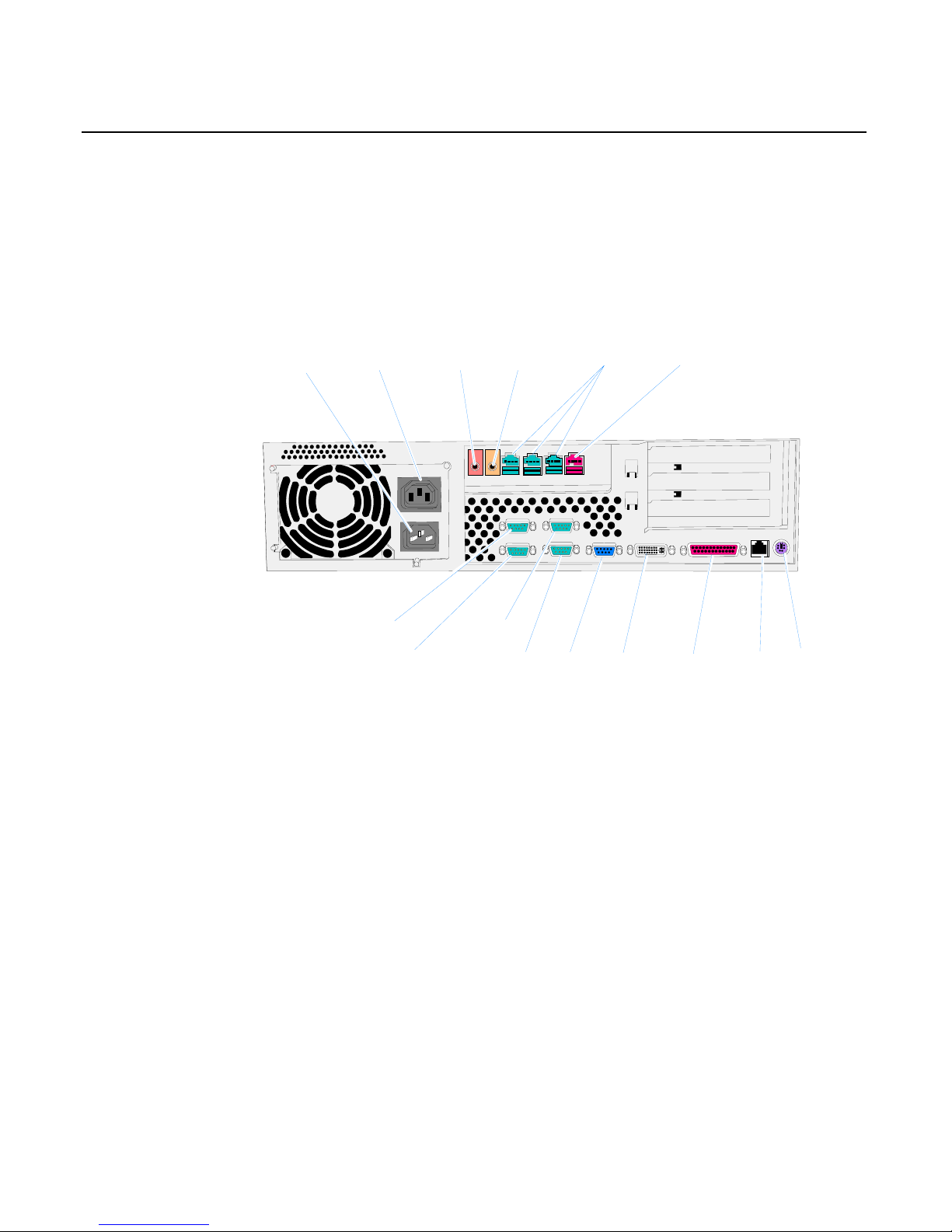
Back Panel Cable Connectors
The following illustrations identify the Back Panel connectors. The
optional USB Daughter Card has three 12V USB+ connectors, one 24V
USB+ connector, and Audio connectors.
20376
Audio
Out
Mic
* RS232/A
RS232/B
* RS232/C * RS232/D
VGA
DVI-I Parallel LAN
PS/2
12V USB 24V USBAC Input Accessory AC
Mic
Audio Out
(* Powered Serial Port)
3-4 Chapter 3: Hardware Service
Electronics Box Disassembly Procedures
This section explains how to disassemble the 7458 for service purposes.
Warning: Disconnect the AC power cord before disassembling the
Terminal.
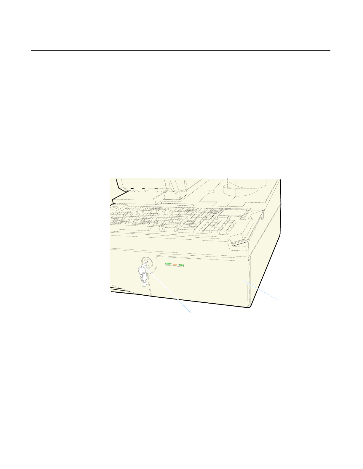
Removing the Electronics Tray
1. Disconnect all cables from the back of the Electronics Box.
2. Turn the Security Door Key to the unlocked position.
20344
Key in Unlocked Position
Security Door

Chapter 3: Hardware Service 3-5
3. Open the Security Door.
4. Pull the Release Latch forward to release the Electronics Tray.
20346
Release Latch
5. Slide the Electronics Tray out of the cabinet. About half way out
there is a Tray Stop on the side of the tray. Press in on the stop to
remove the Electronics Tray from the cabinet.
20348
Tray Stop
Replacing the Electronics Tray
Slide the Electronics Tray into the cabinet until it latches. Make sure the
Release Latch is completely closed in the lock position.
3-6 Chapter 3: Hardware Service
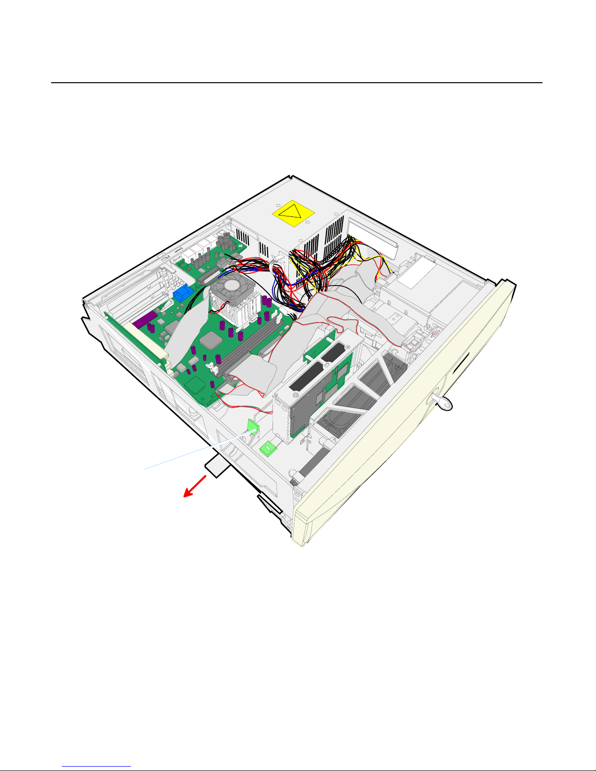
Removing the Motherboard
1. Release the Motherboard Tray Slide Latch and slide the tray toward
the front of the terminal.
20321
Motherboard Tray
Slide Latch
 Loading...