

USER GUIDE
NCR RealPOS 72
XRT
POS (7616)
Release 1.1
B005-0000-2228
Issue C

The product described in this document is a licensed product of NCR Corporation.
NCR is a registered trademark of NCR Corporation. NCR RealPOS is a trademark of NCR Corporation in the United States
and/or other countries. Other product names mentioned in this publication may be trademarks or registered trademarks of their
respective companies and are hereby acknowledged.
The terms HDMI and HDMI High-Definition Multimedia Interface, and the HDMI Logo are trademarks or registered trademarks
of HDMI Licensing LLC in the United States and other countries.
Where creation of derivative works, modifications or copies of this NCR copyrighted documentation is permitted under the terms
and conditions of an agreement you have with NCR, NCR's copyright notice must be included.
It is the policy of NCR Corporation (NCR) to improve products as new technology, components, software, and firmware become
available. NCR, therefore, reserves the right to change specifications without prior notice.
All features, functions, and operations described herein may not be marketed by NCR in all parts of the world. In some instances,
photographs are of equipment prototypes. Therefore, before using this document, consult with your NCR representative or NCR
office for information that is applicable and current.
To maintain the quality of our publications, we need your comments on the accuracy, clarity, organization, and value of this book.
Please use the link below to send your comments.
EMail: FD230036@ncr.com
Copyright © 2015
By NCR Corporation
Duluth, GA U.S.A.
All Rights Reserved

Preface
Audience
This book is written for hardware installer/service personnel, system integrators, and
field engineers.
Notice: This document is NCR proprietary information and is not to be disclosed or
reproduced without consent.
Safety Requirements
The NCR RealPOS 72XRT conforms to all applicable legal requirements. To view the
compliance statements see the NCR RealPOS Terminals Safety and Regulatory Statements
(B005-0000-1589).
Caution: The on/off switch is a logic switch only. The AC line voltage primaries are
live at all times when the power cord is connected. Therefore, disconnect the AC power
cord before opening the unit to install features or service this terminal.
iii
Lithium Battery Warning
Warning: Danger of explosion if battery is incorrectly replaced. Replace only with
the same or equivalent type as recommended by the manufacturer. Discard used
batteries according to the manufacturer's instructions.
Attention: Il y a danger d'explosion s'il y a remplacement incorrect de la batterie.
Remplacer uniquement avec une batterie du même type ou d'un type recommandé par
le constructeur. Mettre au rébut les batteries usagées conformément aux instructions du
fabricant.
Battery Disposal (Switzerland)
Refer to Annex 4.10 of SR814.013 for battery disposal.
IT Power System
This product is suitable for connection to an IT power system with a phase-to-phase
voltage not exceeding 240 V.

iv
Peripheral Usage
This terminal should only be used with peripheral devices that are certified by the
appropriate safety agency for the country of installation (UL, CSA, TUV, VDE) or those
which are recommended by NCR Corporation.
Warning: DO NOT connect or disconnect the transaction printer while the terminal
is connected to AC power. This can result in system or printer damage.
Warning: DO NOT connect or disconnect any serial peripherals while the terminal
is connected to AC power. This can result in system or printer damage.
Grounding Instructions
In the event of a malfunction or breakdown, grounding provides a path of least
resistance for electric current to reduce the risk of electric shock. This product is
equipped with an electric cord having an equipment-grounding conductor and a
grounding plug. The plug must be plugged into a matching outlet that is properly
installed and grounded in accordance with all local codes and ordinances. Do not
modify the plug provided – if it will not fit the outlet, have the proper outlet installed by
a qualified electrician. Improper connection of the equipment-grounding conductor can
result in a risk of electric shock.
References
The conductor with insulation having an outer surface that is green with or without
yellow stripes is the equipment-grounding conductor.
If repair or replacement of the electric cord or plug is necessary, do not connect the
equipment-grounding conductor to a live terminal. Check with a qualified electrician or
service personnel if the grounding instructions are not completely understood, or if you
are in doubt as to whether the product is properly grounded.
Use only 3-wire extension cords that have 3-prong grounding plugs and 3-pole
receptacles that accept the product’s plug. Repair or replace damaged or worn cords
immediately.
• NCR RealPOS 72XRT Site Preparation Guide (B005-0000-2229)
• NCR RealPOS 72XRT Hardware Service Guide (B005-0000-2230)
• NCR RealPOS 72XRT Parts Identification Manual (B005-0000-2231)

Out of Box Failure (OBF)
If you experience an out of box failure (OBF) during installation or staging related to a
missing, wrong or defective unit or item, simply provide NCR with a detailed
description of the issue and the item will be replaced free of charge. For assistance with
this process send an email to CustomerSat.Retail@ncr.com with the following details:
• NCR Sales Order # (Sales Order # are located on the box)
• Date of Product Installation
• Product Model #
• Unit Serial #
• NCR part # of defective/missing/wrong component
• Description of Failure (please be specific. For example: “display will not power on”)
• Customer/Requester's contact name, phone number and/or e-mail address
• Address to ship replacement part(s)
v
Warranty
Transport the product n its original packaging to prevent impact damages.
If you do not have access to a computer, you may leave a voice message at: 1-800-5288658 (USA), or (International) +1-770-623-7400. When leaving a message, please provide a
phone number and/or an email address so NCR can contact you if additional details are
needed.
Note: Used equipment that experiences a failure does not qualify as an OBF and
should go through the NCR warranty process.
Warranty terms vary by region and country.
All parts of this product that are subject to normal wear and tear are not included in the
warranty. In general, damages due to the following are not covered by the warranty.
• Improper or insufficient maintenance
• Improper use or unauthorized modifications of the product.
• Inadequate location or surroundings. Site installation must conform to guidelines
listed in the RealPOS XR7 Site Preparation Guide (B005-0000-2333) and the NCR
Workstation and Peripheral AC Wiring Guide (BST0-2115-53).
For detailed warranty arrangements please consult your contract documents.

vi
Returning Defective Hardware for Service
Use the following procedure to report/return defective hardware.
Call the NCR Customer Care Center at 1-800-262-7782 and have the following information
available when you place the call.
• Class/Model number of the defective equipment
• Serial Number of the defective equipment
• Equipment location in the store
• Description of the problem, including any system error codes, error condition, or
guidance to the area of failure.
The NCR Agent will provide you with a work order number, which serves as your
Return Material Authorization (RMA). Please provide the RMA on the outside of the
shipping box.
Note: A work order must be opened for each device that is shipped for repair.
Shipping Address:
NCR Corporation-DCA Depot
200 Hwy 74 South
Peachtree City, GA 30276
Attn: Dock Door 8

Table of Contents
Chapter 1: Product Overview
Introduction 1
Product IDs 1
Terminal Dimensions and Weights 1
Configurations 2
GMS Integration Tray Kit (7403-K300) 2
Hospitality Integration Tray Kit (7403-K301) 3
Integrated Customer Displays 4
Display Wall Mount (7403-K321) 6
Model and Serial Number Labels 7
Features 8
Key Features 8
vii
Processor 8
Motherboard 8
Memory 8
Storage Options 8
Connectivity 9
Display 10
Consumer Display Options 10
Operating Systems 10
Power Management 10
Cabinet 10
Base Model Comparison 12
MSR 14
Rear Signage 15
Port Security 16
I/O Board 17
I/O Board Connectors 18
Power Management 20
USB Wakeup 20
Definitions of the States 20
G3 Mechanical Off 20

viii
G2/S5 Soft Off 20
G1 Sleeping 20
G0 Working 21
ACPI Sleep States (S0 - S5) 21
ACPI States for Windows 23
Enabling Wake on LAN 24
Windows 7 24
Windows XP 27
Remote Customer Displays 30
NCR 5976 2x20 LCD Customer Display 30
Character Sets 31
NCR RealPOS 5943 12.1-Inch LCD 32
NCR RealPOS 5943 15-Inch LCD 33
NCR RealPOS 5967 12.1-Inch Touch LCD 34
NCR RealPOS 5967 15-Inch Touch LCD 35
NCR 5982 6.5-Inch LCD Display 36
Transaction Printers 37
NCR RealPOS 7167 Printer 37
NCR RealPOS 7168 Printer 38
NCR RealPOS 7198 2ST Printer 39
Chapter 2: Installing the Terminal
Introduction 41
Installation Summary 42
Installation Restrictions 42
Connecting the External Cables 43
Accessing the I/O Panel 44
Powered Serial Port Jumper Settings and Fuses 46
Accessing the Backplane Connectors 47
AC Power Cord Connection 48
Cable Routing 49
Cable Routing from the I/O Board 50
Terminal Configured with a DVD-ROM Drive 50
Terminal without a DVD-ROM Drive 51
Cable Routing from the Backplane Board 53
Optional VGA Extension Cable 54
Removing the Storage Media 56

Powering Up the Terminal 57
Terminal On/Off Switch 57
Power Button Override 57
Default Boot Order 58
Keyboard support 58
Connecting peripherals 58
Calibrating the Touch Screen 58
Out-of-Box Failures 59
Chapter 3: POST Diagnostics
Diagnostic LEDs 61
Beep Codes 63
Boot Block Beep Codes 63
POST BIOS Beep Codes 63
ix
Chapter 4: Touch Screen Calibration
Introduction 65
Installing the Driver 66
Touch Methods 67
Calibration Procedures 71
Verifying the Calibration 74
Optional Settings 75
Chapter 5: Configuring a Secondary Display
Introduction 77
Setting the Display Mode 78
Intel Graphics Controller Hot Keys 80
Chapter 6: Configuring AMT
Configuring the Terminal 81
Logging onto the Terminal Using AMT 87
Function Definitions 90
Hardware Information 90
Removing the Hard Disks 91
Chapter 7: Installing Optional Remote Peripherals
Introduction 93
Cable Routing 93

x
Installing a Transaction Printer 94
USB Installation 94
RS-232 Installation w/Power from Powered USB 95
Installing a Remote Customer Display 96
NCR RealPOS 5943 12-inch LCD Cable Connections 98
VGA Connections 99
Powered USB Cable Connections 100
NCR RealPOS 5943 15-inch LCD Cable Connections 101
VGA Connections 102
Powered USB Cable Connections 103
NCR RealPOS 5967 12-inch Touch LCD Cable Connections 104
VGA Connections 105
Powered USB Cable Connections 106
NCR RealPOS 5967 15-inch Touch LCD Cable Connections 107
VGA Connections 108
Powered USB Cable Connections 109
Installing an NCR 5975/5976 Remote Customer Display 110
USB Interface (Powered) 114
RS-232 Interface (Powered) 114
Installing a Cash Drawer 115
Installing a Second Cash Drawer 116
Chapter 8: Configuring a Second HDD for RAID
Introduction 117
Configuring a RAID System 117
Installation Procedures 118
Replacing a Failed RAID 1 (Mirrored) HDD 123
Failed Disk Replacement Procedure 124
Chapter 9: 2x20 Customer Display Interface
Introduction 127
General Specifications 127
Serial Communication Interface 127
Command Codes 128
User Defined Character Definition (08h, CODE, Byte1…Byte5) 128
Character Table Select (09h, TABLE CODE) 129
Clear Display (12h) 129
Luminance Control (11h, LUMINANCE) 129

Cursor Position (10h, POSITION) 130
Reset (13h) 130
Character Tables and Codes 131
CP437 132
CP858 133
CP866 134
CP932 135
Chapter 10: BIOS Setup
Entering Setup 137
How to Select Menu Options 137
Restoring Factory Settings 137
Disabling Resources 137
Keyboard Shortcuts 138
xi
BIOS Default Values 140
Main Menu 140
Advanced Menu 140
Chipset Menu 147
Boot Menu 152
Chapter 11: BIOS Updating Procedure
Introduction 153
Prerequisites 153
Creating a Bootable USB Drive 154
SPI/BIOS Updating Procedures 154
Manually Updating the MAC Address 158
Chapter 12: Operating System Recovery
Introduction 159
Prerequisites 159
Procedures for Windows XP Pro/POSReady 2009 159
OS Recovery Procedures for Windows 7/POSReady 7 161
Chapter 13: Solid State Drive Optimization
About the Intel® SSD Optimizer 165
Intel® SSD Optimizer Requirements 165
Installation and Startup 167
Requirements 167

xii
Installation 167
Starting the Intel SSD Toolbox 168
Manually Running the Intel® SSD Optimizer 169
Scheduling the Intel® SSD Optimizer 172
Removing a Scheduled Intel® SSD Optimizer Session 176
Additional Information 176
Known Limitations 177
Known Issues 178
Chapter 14: Touch Screen Operation
Introduction 181
Touch Mode of Operation 181
Changing the Touch Mode 182
Turning Off the Mouse Pointer 183
Terminal Placement 186
Chapter 15: Maintenance
Cabinet and Touch Screen Cleaning Procedures 187
Cleaners/Solvents to Use 187
Cleaners/Solvents to NOT Use 187
Cooling Vent Cleaning 188
Procedure 188
MSR Cleaning Procedures 189
MSR Cleaning and Treatment Cards 189
MSR Treatment Card 189
Cleaning/Treatment Frequency 190
Chapter 1: Product Overview
Introduction
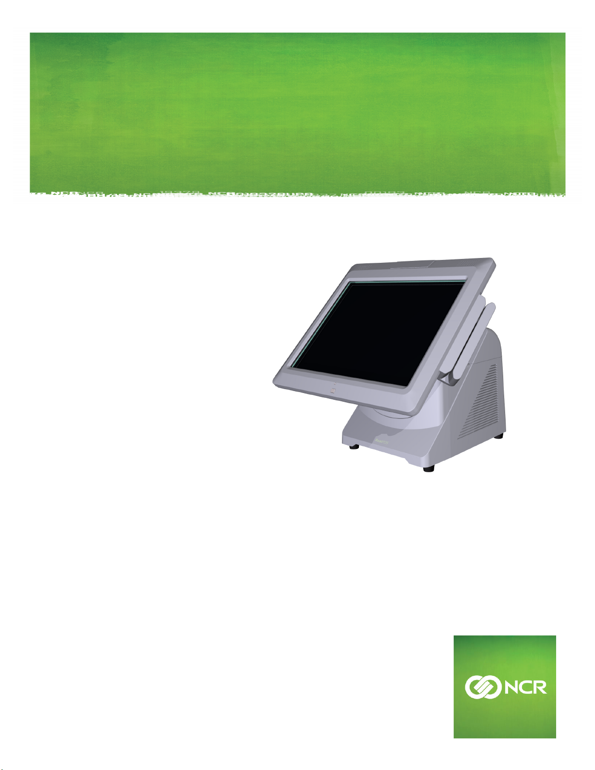
The NCR RealPOS 72XRT (also referred to as NCR 7616) is a scalable, retail-hardened
Integrated Point-of-Sale. The NCR RealPOS 72XRT offers an intuitive capacitive touch
screen interface plus a variety of retail consumer interfaces. The product is designed for
extended life cycles, stability and superior availability. The terminal has been enhanced
to offer even better serviceability and scalability than previous generations.
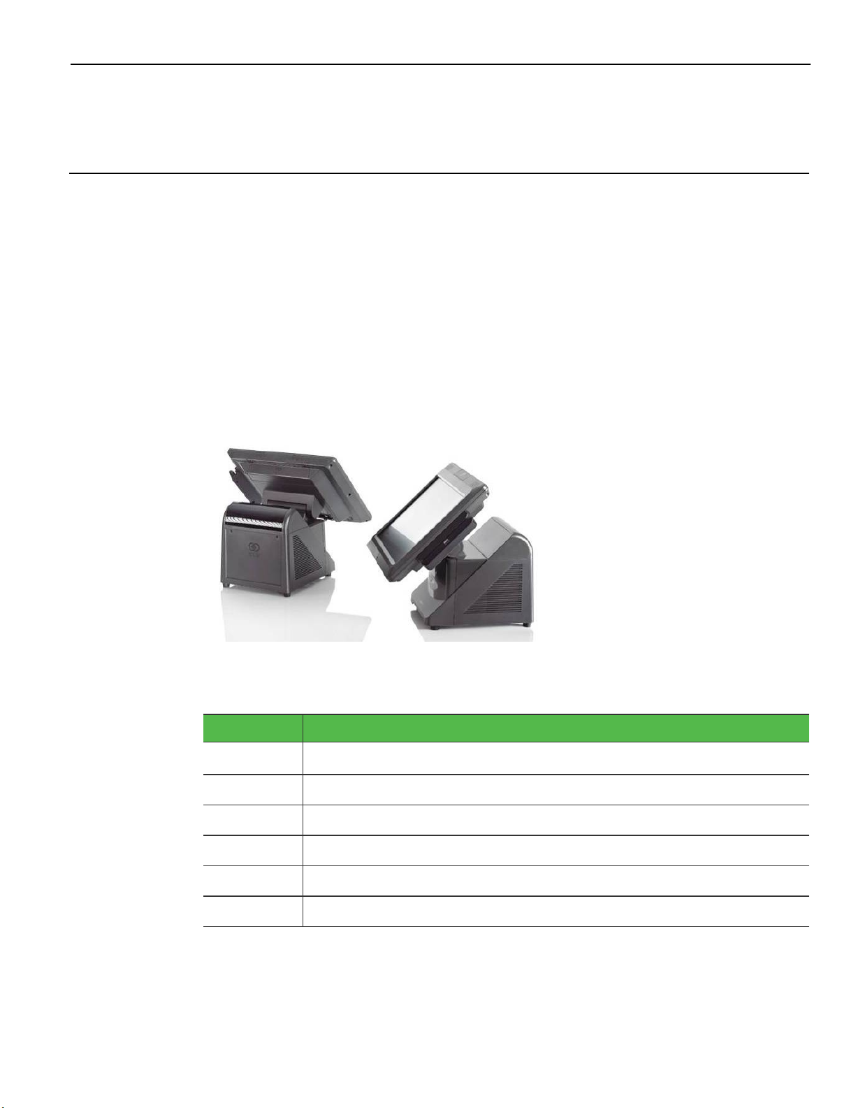
Engineered to thrive in the most demanding environments, the NCR RealPOS 72XRT
offers retailers in Hospitality, Convenience Stores, and General Merchandise a POS
platform that offers exceptional value for their POS investment.
Product IDs
Major Model CPU
7616-1201
7616-1301 7616 Base, Intel i3 CPU, 4GB DDR3, Diskless
7616-1501 7616 Base, Intel i5 CPU, 4GB DDR3, Diskless
7616-0015 7616 Display, 15", Capacitive Touch (for Base or Remote Mount)
7616-0045 7616 Display, 15", Capacitive Touch (for Base or Remote Mount)
7616-0017 7616 Display, 17", Capacitive Touch (for Base or Remote Mount)
7616 Base, Intel Celeron G530T CPU, 4GB DDR3, Diskless
Terminal Dimensions and Weights
See the NCR RealPOS 72XRT Site Preparation Guide, B005-0000-2229.
1-2 Product Overview
Configurations
There are field upgradeable kits for the NCR RealPOS 72XRT that provide for many
configuration variations. This section illustrates each of these and lists the associated
kits.
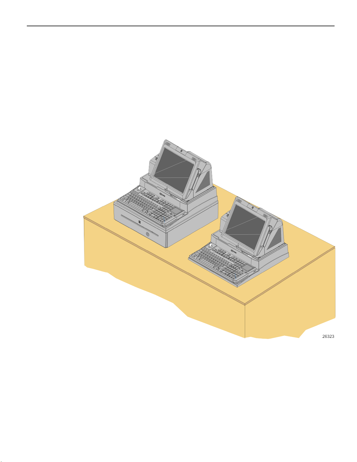
GMS Integration Tray Kit (7403-K300)
This kit provides the necessary components for integrating a printer and keyboard with
the NCR RealPOS 72XRT terminal for a General Merchandise environment. It can be
mounted on a flat surface or on a cash drawer.
Product Overview 1-3
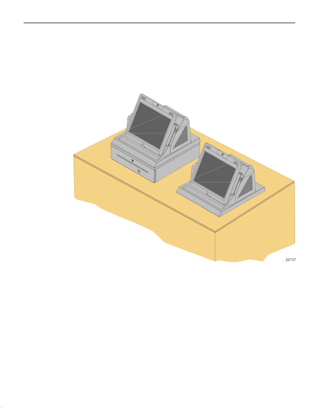
Hospitality Integration Tray Kit (7403-K301)
This kit provides the necessary components for integrating a printer with the NCR
RealPOS 72XRT terminal for a Hospitality environment. It can be mounted on a flat
surface or on a cash drawer.
1-4 Product Overview
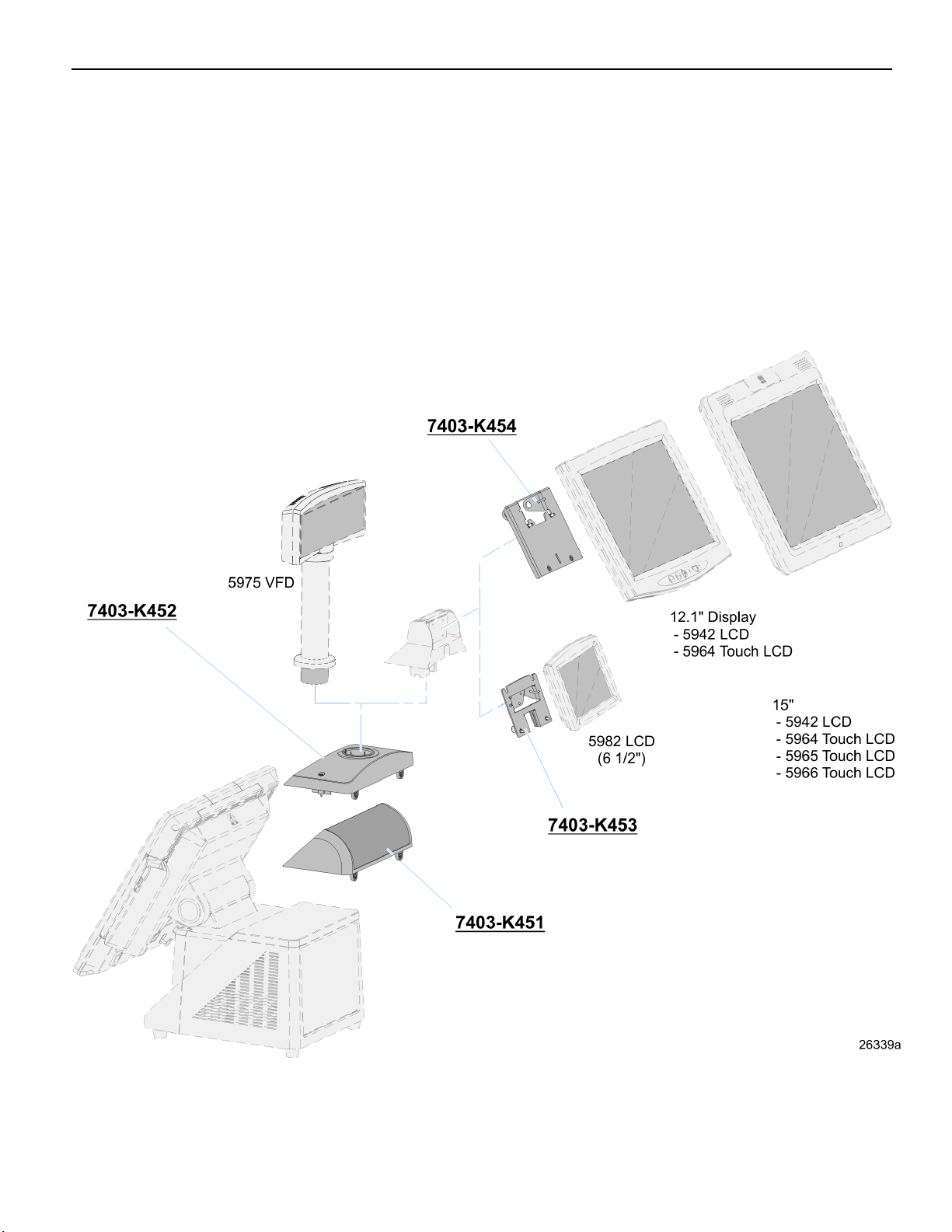
Integrated Customer Displays
There are various kits that are used for integrating VFD and LCD customer displays on
the back of the NCR RealPOS 72XRT terminal.
• 7403-K451: Integrated 2x20 Customer Display
• 7403-K452: Rear Consumer Display Pole Mount (for 5975 Display)
• 7403-K453: Rear Consumer LCD Hinge Assembly - Small (Small displays)
• 7403-K454: Rear Consumer LCD Hinge Assembly - Large (Large displays)
Product Overview 1-5
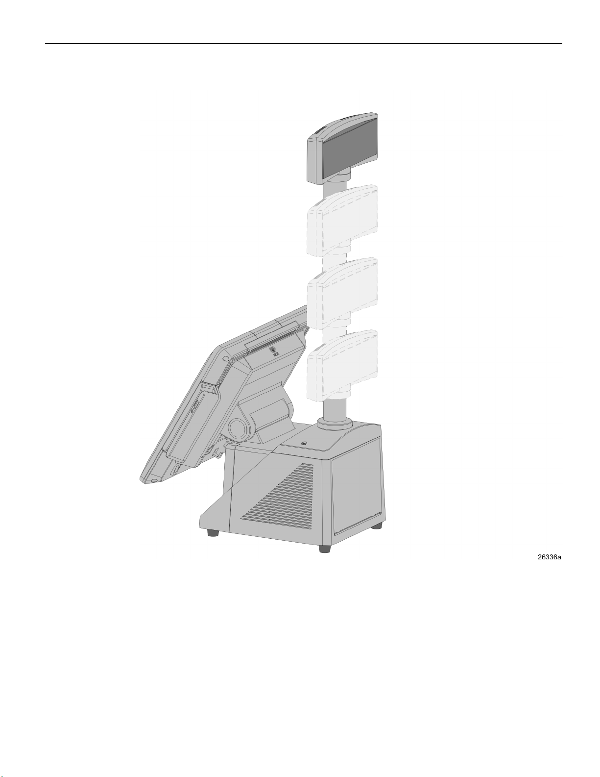
There are four post options for the 5975 display, available in 4 inch increments

1-6 Product Overview
Display Wall Mount (7403-K321)
This kit is used in to install a 7616 Display Head remotely on a vertical surface.
Product Overview 1-7
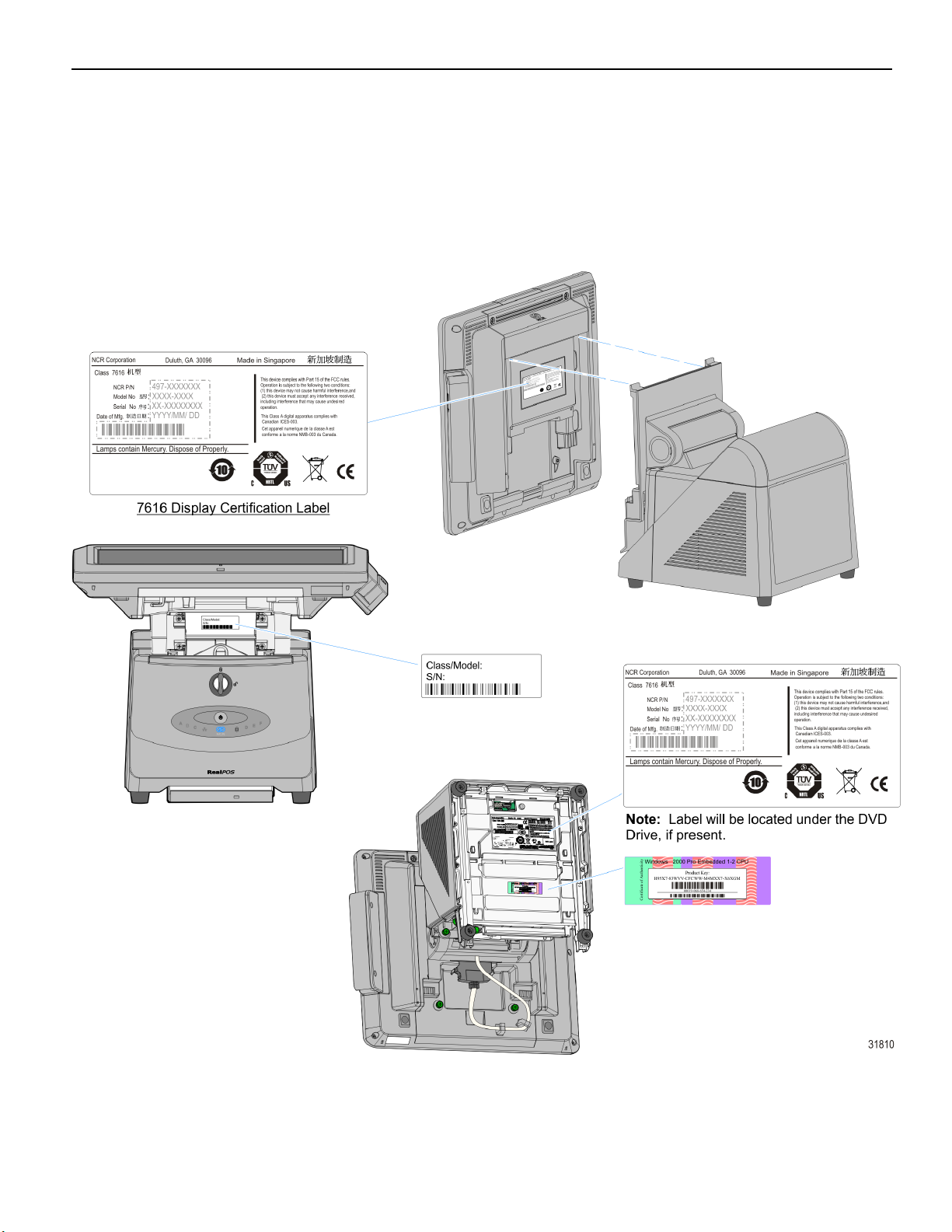
Model and Serial Number Labels
The serial number and model number labels located on the back of the Display Head, on
the top back edge of the Display Head, and on the bottom of the Base. If the terminal
was shipped with an Operating System pre-installed then there is also a Certificate of
Authenticity label on the bottom of the Base.

1-8 Product Overview
Features
Key Features
• Extreme performance with Intel® Core™ processor family
• Fast and reliable capacitive touch screen with full-tilt capability
• Integrated compact design with customizable customer-facing display system
• Reduced power consumption with energy-efficient Intel processor technology and
high-efficiency 80 PLUS power supply
• Innovative EZ-Glide Blade System provides tool-free front-access for service and
upgrades
• Advanced systems management capabilities with Intel® AMT
Processor
• Intel® G1610T processor (2.3Ghz)
• Intel® Core™ i3-3240T processor (2.9GHz)
• Intel® Core™ i5-3470T processor (3.2GHz)
Motherboard
• Intel® Q67 Express Chipset
• Intel® Integrated HD Graphics
• Intel® Matrix Storage Technology (MST)
• SATA III 6Gb/s storage interface
Memory
• 4GB - 16GB system memory
• Dual-channel DDR3 (1333MHz)
• Two DIMM memory sockets
Storage Options
• 3.5” 250GB SATA hard disk drive
• Dual 2.5” SATA hard disk drives with RAID
• 2.5” SATA solid state drive (SSD)
• Internal 24x CD/DVD-ROM drive

Product Overview 1-9
Connectivity
• 12 USB ports total:
• 4 PC USB (5V)
• 2 powered USB (12V)
• 1 powered USB (24V printer)
• 5 dedicated USB ports (reserved)
Note: For security purposes individual USB ports can be disabled in the BIOS at:
Chipset >> PCH-IO Configuration >> USB Configuration >>
USB Ports Per-Port Disable Control >> Enabled.
• 5 RS-232 ports (selectable power 0/5/12V)
• 10/100/1000 MB (Gigabit) Ethernet LAN
• VGA Port (dual independent display support)
• Audio ports:
• Rear channel line out
• Line in (mic)
• Integrated USB wireless option
• Dual Cash Drawer Support
• Single Connector for Backwards Compatibility
• Connected through a cash drawer Kickout connector on the I/O Board or
through the cash drawer Kickout connector on the transaction printer.
• The terminal can be configured with 0, 1, or 2 cash drawers. The first drawer is
attached to the terminal through a cable with an RJ-45 connector. A second
drawer can be connected using a 'Y' cable.
Note: A single Open/Close status signal is shared with both drawers. Therefore, it is
not possible to determine which cash drawer is open.
Note: The terminal has a protection diode on board to limit back EMF from the
solenoid when the solenoid turns off. Third party cash drawers should also have a
diode installed across the solenoid to further reduce potentially damaging overshoot
from the solenoid. This diode is present on all NCR cash drawers.

1-10 Product Overview
Display
• 15” capacitive touchscreen
• 17” capacitive touchscreen
• High-brightness LCD
• Full-tilt capability (0˚ - 90˚)
• Integrated stereo speakers
• Motion sensor
Display Options
• Integrated 3-track ISO MSR
• Integrated biometric fingerprint reader
Consumer Display Options
• 2 x 20 VFD (integrated or pole mount)
• All Points Addressable (APA) display
• 6.5”, 12” or 15” LED LCD display
• 15” Capacitive touchscreen
Operating Systems
• Window 7 Professional
• Windows XP Professional
• Windows Embedded POSReady 7
• Windows Embedded POSReady 2009
• SUSE Linux Enterprise for Point-of-Service (SLEPOS)
Power Management
• 80 PLUS certified power supply (230 watt capacity)
• ACPI 3.0 compliant
Cabinet
• Tool-Free Front Accessible Components
• Motherboard on a Removable Sled
• One or Two SATA Hard Drives
• DVD ROM Drive
• Power Button
• Nine Visible LEDs

Product Overview 1-11
• Lighted Logo to Indicate Power On / Suspend Mode
• LAN Link Activity
• Hard Drive Activity
• Six Diagnostic LEDs

1-12 Product Overview
Base Model Comparison
RealPOS 72XRT Base (Class 7616) Standard Model 1200
Performance
Model 1300
Extreme Model
1500
Processor Celeron G530T Core i3-2120T Core i5-2390T
Clock Speed 2Ghz 2.6GHz 2.7GHz
Cache 2MB 3MB
CPU Cores
2
Chipset Intel Q67 express
Thermal Design Power
AMT 8 *
Memory
MEMORY TYPE
Memory Slots
STANDARD MEMORY
Maximum System Memory
Note: Chipset supports 32GB. 72XRT has 2
35 Watts
Yes
DDR3 1333MHz
2 DIMM
1 x 4GB
8GB(2 x 4GB)
memory slots. 4GB is largest memory
module certified and released at this
time.
Dynamic Video Memory Technology
(DVMT) 5.0
Dynamic Video Memory Technology (DVMT) 5.0 supports the
selection of several increased sizes of pre-allocated
memory.This amount is chosen via the system BIOS as a setup
option
Connectivity
RS-232 Total
5
RS-232, 0/5/12V (front I/O) 4
RS-232, 12V (dedicated) 1 (rear customer display)
USB Total
12
USB, 5V PC (front I/O) 4
USB, 12V Powered (front I/O) 2
USB, 24V Powered (front I/O) 1
USB, 5V (dedicated – touch display &
4(operator touch, MSR, biometrics, wireless)
integrated options)

Product Overview 1-13
RealPOS 72XRT Base (Class 7616) Standard Model 1200
USB, 5V (dedicated – rear consumer
Performance
Model 1300
1(consumer touch display)
Extreme Model
display system)
Dual Independent Display Support Standard
Video Interface – Consumer 1 – VGA(supports Hi-definition)
Ethernet LAN 10/100/1000Mb
Cash Drawer Ports 1 (supports 2 cash drawers via Y cable)
Storage / Expansion
Single SATA Hard Disk Drive 3.5” 250GB Option
Dual SATA Hard Disk Drives Dual 2.5” 250GB Option
Solid State Drive (SATA)
Integrated Optical Drive Option (SATA)
Onboard RAID support
15” or 17” Touch Display
2.5” 40GB SSD Option
CD/DVD ROM Option
Standard
1500
Brightness (15 and 17)
Screen Life (15 and 17)
Integrated Speakers
Integrated 3 track ISO MSR
Integrated USB Wireless
Integrated Biometrics
Consumer Displays
2 x 20 VFD
All Points Addressable VFD
6.5” Color LCD
12” Color LCD
15” Color LCD
15” Color LCD with Touch
Power Supply
High Bright
50K Hours
Standard
Option
Option
Option
Option
Option
Option
Option
Option
Option
80Plus Certified 230 Watt
1-14 Product Overview
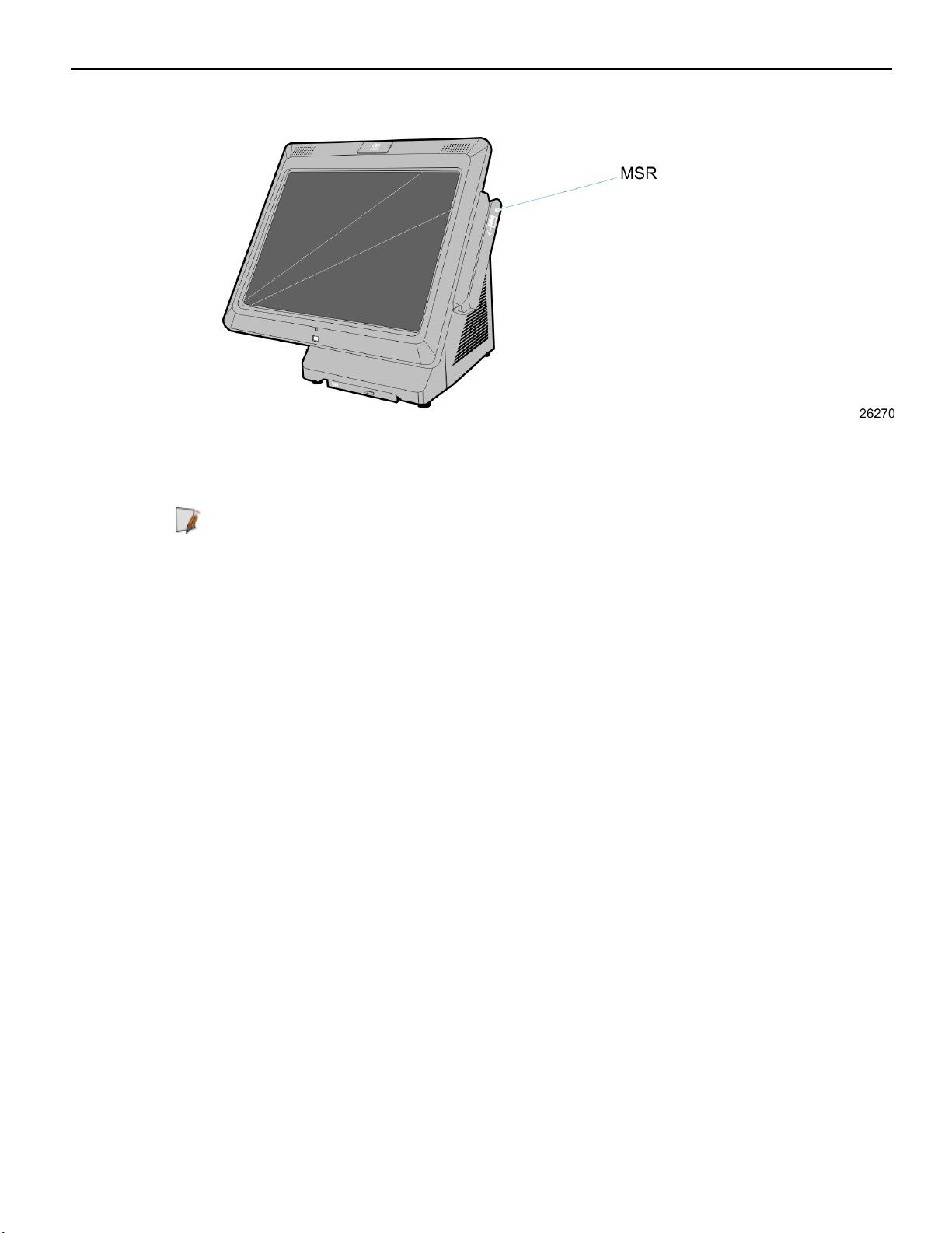
MSR
The MSR interface supports a maximum of 3 tracks of magnetic stripe information to
support ISO format cards. The MSR is by default an OPOS device but can be
reprogrammed for use with keyboard stream applications.
Note: See the NCR MSR Configuration User Guide (B005-0000-2031) Issue D (or later) for
details on how to configure the MSR for keyboard stream applications.
Product Overview 1-15
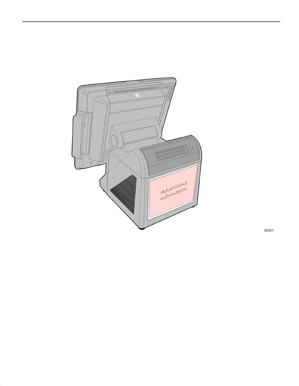
Rear Signage
Customer provided signage information (7.25" x 5.5") can be displayed on the back of the
7616. Plastic covers are required to hold the sign in place. The Signage Kit (7403-K455)
contains 5 plastic inserts for this purpose.
1-16 Product Overview
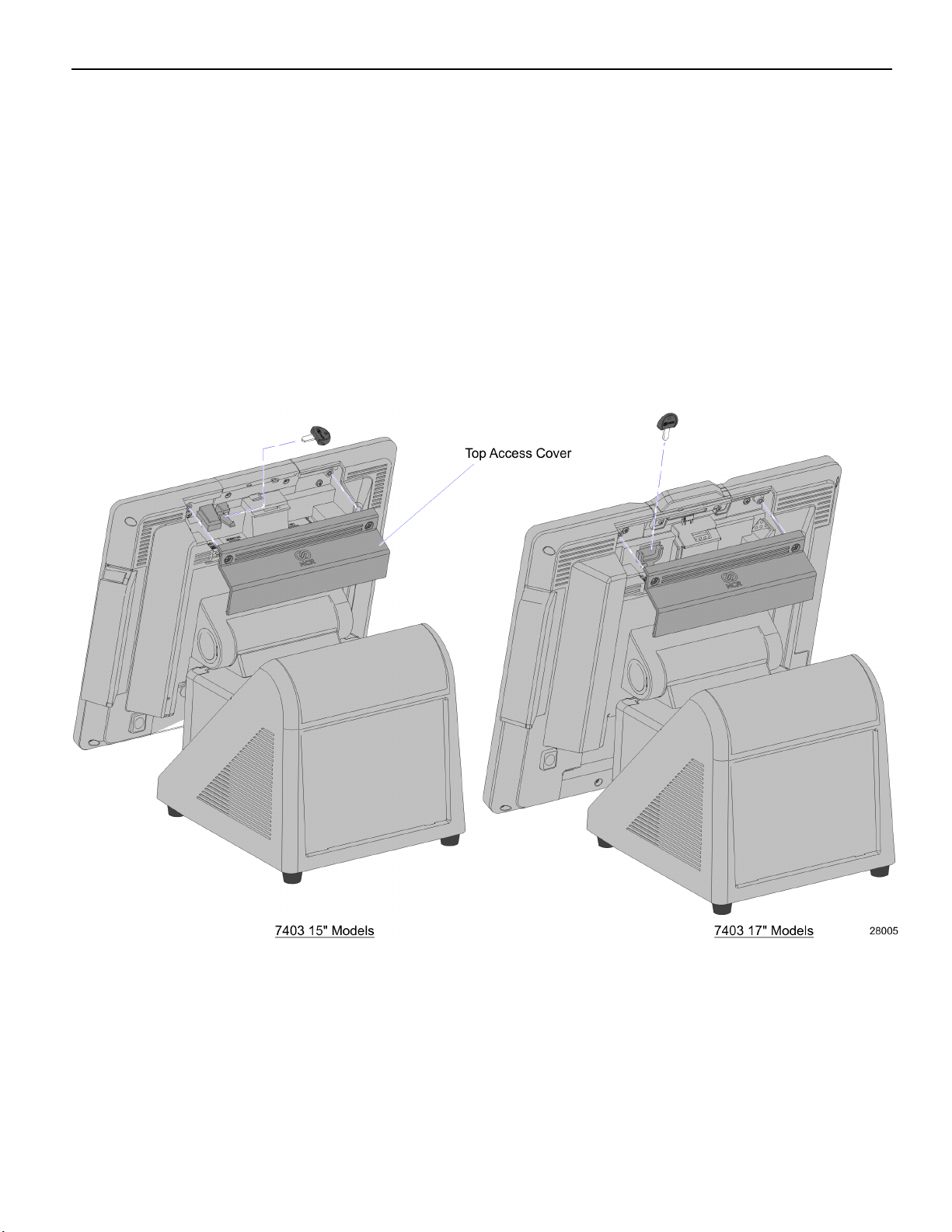
Port Security
The NCR RealPOS 72XRT provides communication port security by protecting all
connections via a key lock or a cover requiring tools to open. This keeps the terminal
safe from users that might try to remove data or inject a virus via a USB port or other
connection.
Some customers may prefer to keep a key attached to the terminal for service purposes.
The NCR RealPOS 72XRT provides a means to hide the key inside the terminal display
head. To access this you must remove the Top Access Cover on the back of the display
(2 captive screws). Insert the key into the molded key slot. Be sure the key is secure
before closing the rear access door.
Product Overview 1-17
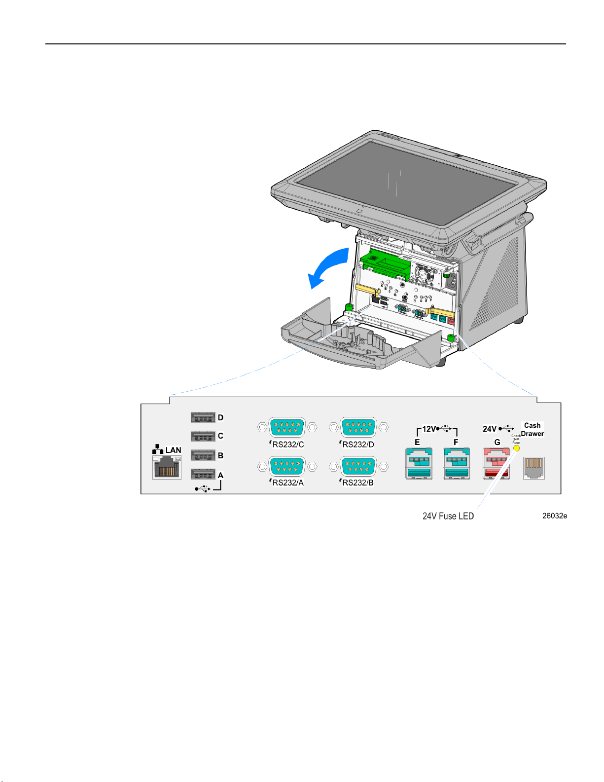
I/O Board
The I/O Board is used to provide external connections for the motherboard. It slides into
position in the terminal below the motherboard.

1-18 Product Overview
I/O Board Connectors
• Ethernet
• One 10/100/1000 MDI port
• USB
• Four High Speed Ports. Each port is capable of supplying 5 V at 0.5 A max. Self
healing polyfuses are used to provide current protection.
• Two 12 V High Speed USB+Power ports. Each port is capable of supplying 12 V
at 2.0 A max. Connected peripherals must not exceed this rating. Self healing
polyfuses are used to provide current protection.
• One 24 V High Speed USB+Power ports. The port is capable of supplying 24 V at
0.5 A continuous and 3.0 A peak. A self-healing Poly-Fuse is used to provide
current protection.
• Serial Ports (4)
• RS-232 ports with selectable power (+5 V, +12 V, or RI) on pin 9. (One RS 232
port is connected to the backplane and is available on the Backplane Board.)
Note: By default, Windows assigns COM 1-4 to the COM ports on the front of the
terminal (labeled COM A-D). Additionally, there is a COM port on the back of the
terminal, which is dedicated to integrated customer displays. Windows assigns
COM6 to this port. Finally, there is an internal COM5, which is used by the
Advanced Management Technology feature.
• Cash drawer Kickout port
• Support for two cash drawers on a single port
 Loading...