

NCR RealPOS 7199 User Manual
User Guide
NCR RealPOS 7199 Thermal Receipt
Station Printer
Release 1.0
BCC5-0000-5172
Issue B

ii
The product described in this document is a licensed product of NCR Corporation.
NCR is a registered trademark of NCR Corporation. NCR RealPOS is a trademark of NCR Corporation in
the United States and/or other countries. Other product names mentioned in this publication may be
trademarks or registered trademarks of their respective companies and are hereby acknowledged.
The terms HDMI and HDMI High-Definition Multimedia Interface, and the HDMI Logo are trademarks or
registered trademarks of HDMI Licensing LLC in the United States and other countries.
Where creation of derivative works, modifications or copies of this NCR copyrighted documentation is
permitted under the terms and conditions of an agreement you have with NCR, NCR's copyright notice
must be included.
It is the policy of NCR Corporation (NCR) to improve products as new technology, components, software,
and firmware become available. NCR, therefore, reserves the right to change specifications without prior
notice.
All features, functions, and operations described herein may not be marketed by NCR in all parts of the
world. In some instances, photographs are of equipment prototypes. Therefore, before using this document,
consult with your NCR representative or NCR office for information that is applicable and current.
To maintain the quality of our publications, we need your comments on the accuracy, clarity, organization,
and value of this book. Please use the link below to send your comments.
Email: FD230036@ncr.com
Copyright © 2018
By NCR Corporation
Atlanta, GA U.S.A.
All Rights Reserved

Preface
Audience
This book is written for hardware installer/service personnel, system integrators, and
field engineers.
Notice: This document is NCR proprietary information and is not to be disclosed or
reproduced without consent.
Safety Requirements
Important Information to the User
In order to ensure compliance with the Product Safety, FCC and CE marking
requirements, you must use the power supply, power cord, and interface cable which
were shipped with this product or which meet the following parameters:
iii
Power Supply
UL Listed (QQGQ), Class 2 power supply with SELV (Secondary Extra Low Voltage),
non–energy hazard output, limited energy source, input rated 100–240 Vac, 1.5/0.8 A,
50/60 Hz, output rated 24 Vdc, 2.3 A. or 3.125A.
Use of this product with a power supply other than the NCR power supply will require
you to test this power supply and NCR printer for FCC and CE mark certification.
Interface Cable
A shielded (360 degree) interface cable must be used with this product. The shield must
be connected to the frame or earth ground connection or earth ground reference at
EACH end of the cable.
Use of a cable other than described here will require that you test this cable with the
NCR printer and your system for FCC and CE mark certification.
Power Cord
A UL listed, detachable power cord must be used for this product. For applications
where the power supply module may be mounted on the floor, a power cord with Type
SJT marking must be used. For applications outside the US, power cords which meet the
particular country’s certification and application requirements should be used.
Use of a power cord other than described here may result in a violation of safety
certifications which are in force in the country of use.

iv
Wichtige Benutzerinformationen:
Um die Produktsicherheit und die FCC und CE–Markierungsanforderungen bei der
Benutzung des Druckers sicherzustellen, müssen entweder das mitgesante Netzgerät,
Netzanschlußkabel und Verbindungskabel verwendet werden oder folgende
Anforderungen müssen erfüllt sein:
Netzgerät:
Das Netzgerät muß ein UL verzeichnetes (QQGQ) Netzgerät der Klasse 2 mit SELV
(Sekundärextraniederspannung), Nichtenergie Gefahrenausgang, begrenzter
Energiequelle, einer Aufnahmeleistung von 100–240 VAC, 1.5/0.8 A und 50/60 Hz, und
einer Leistungsabgabe von 24 VDC, 3.125 A.c sein.
Die Benutzung des Produktes mit einem Netzgerät, daß nicht von NCR mitgeliefert
wurde erfordert das Testen des Netzgerätes mit dem NCR Drucker auf FCC und CE–
Markierungs Befolgung.
Verbindungskabel:
Bei der Benutzung dieses Produkts muß ein abgeschirmtes (360 Grad) Verbindungskabel
benutzt werden. Die Abschirmleitung muß entweder mit dem Rahmens des Gerätes
oder der Erde verbunden sein oder alternativ müssen alle Enden des Kabels geerdet
werden.
Falls das Verbindungskabel nicht in der hier beschrieben Art benutzt wird, muessen das
Kabel und der NCR Drucker auf die FCC und CE–Markierungs Befolgung überprüft
werden.
Netzanschlußkabel:
Für dieses Produkt muß ein in UL aufgelistete, abnehmbares Netzanschlußkabel benutzt
werden. Falls das Netzgerät fest auf dem Boden montiert ist, muß ein Netzanschlußkabel
mit der SJT Markierung benutzt werden. Für Anwendungen außerhalb der USA, sollte
ein Netzanschlußkabel benutzt werden, daß der Zertifizierung und Bestimmung des
jeweiligen Landes entspricht.
Das Abweichen der hier beschriebenen Benutzungsanleitung des
Netzanschlußkabels kann gegen die gesetzlichen Sicherheitsbestimmungen des
jeweiligen Landes verstoßen.
vvivii

Federal Communications Commission (FCC)
Radio Frequency Interference Statement
Warning: Changes or modifications to this unit not expressly approved by the party
responsible for compliance could void the user’s authority to operate the
equipment.
Note: This equipment has been tested and found to comply with the limits for a Class A
digital device, pursuant to Part 15 of the FCC Rules. These limits are designed to provide
reasonable protection against harmful interference when the equipment is operated in a
commercial environment. This equipment generates, uses, and can radiate radio
frequency energy and, if not installed and used in accordance with the instruction
manual, may cause harmful interference to radio communications. Operation of this
equipment in a residential area is likely to cause harmful interference in which case the
user will be required to correct the interference at his own expense.
Communication Cables
Shielded communication cables must be used with this unit to ensure compliance with
the Class A FCC limits.
Information to User
This equipment must be installed and used in strict accordance with the manufacturer's
instructions. However, there is no guarantee that interference to radio communications
will not occur in a particular commercial installation. If this equipment does cause
interference, which can be determined by turning the equipment off and on, the user is
encouraged to contact NCR immediately.
The NCR Company is not responsible for any radio or television interference caused by
unauthorized modification of this equipment or the substitution or attachment of
connecting cables and equipment other than those specified by NCR. The correction of
interferences caused by such unauthorized modification, substitution or attachment will
be the responsibility of the user.

viii
Industry Canada (IC)
Radio Frequency Interference Statement
This Class A digital apparatus meets all requirements of the Canadian Interference–
Causing Equipment Regulations.
Cet appareil numérique de la classe A respecte toutes les exigences du Règlement sur le matériel
brouilleur du Canada.

Bundeskommunikationen Kommission (FCC)
Hochfrequenz–Störungs Richtlinie.
Warnung: Änderungen oder Änderungen an der Maßeinheit, die nicht ausdrücklich
von der Seite, die für die Befolgung verantwortlich ist, genehmigt ist, können zum
Entzug der Benutzungsberechtigung dieses Gerätes führen.
Anmerkung: Dieses Gerät wurde getested und entspricht der zulässigem Richtlinien
eines digitalen Gerätes der Klasse A, gemäß Abschitt 15 in den FCC Richtlinien. Diese
Richtlinien sind dazu da, einen angemessenen Schutz gegen schädliche Störung bei der
komerziellen Nutzung dieses Gerätes zu gewährleisten. Dieses Gerät erzeugt und
benutzt Hochfrequenzenergie und kann Hochfrequenzenergie ausstrahlen. Wenn die
Installierung und Benutzung dieses Gerätes nicht wie im Benutzer Handbuch
beschrieben ist, durchgeführt wird, kann eine schädliche Störung von
Funkverbindungen verursacht werden. Der Betrieb dieses Gerät in einem Wohngebiet
kann schädliche Störung verursachen die auf Kosten des Benutzers behoben werden
müssen.
ix
Kommunikationskabel:
Dieses Gerät muß in Uebereinstimmung mit Kategorie A FCC Richtlinien mit einem
abgeshirmten Kabel betrieben werden.
Benutzerinformationen:
Dieses Gerät muß wie in der Hersteller Anweisungen beschrieben installiert und benutzt
werden. Jedoch gibt es keine Garantie dafür, daß Funkstörung nicht in bestimmten
kommerziellen Installation auftritt. Für den Fall, daß das Gerät Funkstörungen
verursacht, was durch das An und Abschalten des Gerätes festgestellt werden kann,
wird der Benutzer aufgefordert sofort mit NCR Kontakt aufzunehmen.
NCR ist nicht für Radio– oder Fernsehenstörung verantwortlich, die durch
unautorisierte Änderung der Ausrüstung oder den Ersatzes der anschließenden Kabel
oder durch Anschluß von Geräten hervorgerufen wird, die nicht ausdrücklich von NCR
genehmigt wurden sind. Die Korrektur von Störungen, die durch solche unautorisierte
Änderung, Ersatz oder Zubehör verursacht werden, liegt in der Verantwortlichkeit des
Benutzers.
x
Industrie–Kanada (IS)
Hochfrequenz–Störungs Richtlinie:
Dieses digitale Gerät der Klasse A entspricht allen Anforderungen der kanadischen
Störung–Verursachende Geräte Richtlinie.
Caution labels information
Hot Surface, Do not touch / Surface chaude, Ne pas toucher.
Sharp edge. Keep fingers and other body parts away / Tranchant, Tenir les doigts et les autres
parties du corps éloignés.

References
• NCR RealPOS 7199 Thermal Receipt Printer Service Guide (BCC5-0000-5174)
• NCR RealPOS7199 Thermal Receipt Station Printer Parts Identification Manual (PIM)
• NCR RealPOS7197 to 7199 Thermal Receipt Station Printer Migration Guide (BCC5-0000-
• NCR RealPOS7199 Thermal Receipt Station Printer Programmer's Guide (BCC5-0000-
xi
(BCC5-0000-5173)
5175)
5170)

xii
Table of Contents
Chapter 1: NCR RealPOS 7199 Thermal Receipt Station Printer
General Description 1
Features and Options 2
General Features 2
Thermal Print Head 4
Ordering Paper and Supplies 5
Ordering Thermal Receipt Paper 5
Paper grades available from Iconex 5
Other Supplies 6
What is in the Box 8
Removing the Packing Material 8
Repacking the Printer 9
Cleaning the Printer 10
Cleaning the Cabinet 10
Cleaning the Thermal Print Head 10
Choosing a Location 11
Normal Table Top 11
Wall Mounted 11
Connecting the Cables 13
USB Cable Connection 14
Different types of Y–cable routing method 15
RS–232 Cable Connection (Option) 16
Ethernet Cable Connection (Option) 18
Checking for USB Support on the Host Computer 19
Host Configuration 19
Interface Description 20
Human Interfaces 20
Using the Printer 21

Loading and Changing the Receipt Printer 22
Removing the Paper Roll 22
Loading the Paper Roll 24
Advancing the Paper 25
Chapter 2: Troubleshooting Problems
Overview 27
Red LED is off or Printer Will Not Print 28
Amber LED Blinking (Slow) 28
Amber LED Blinking (Fast) 29
Receipt Printing is Light or Spotty 31
Stuck Cutter Blade 32
Other Serious Problems 35
xiii
Contacting a Service Representative 35
Chapter 3: Service Level Troubleshooting
Diagnostics Overview 37
Startup (Level 0) Diagnostics 38
Printer Configuration (Level 1) 39
Runtime (Level 2) Diagnostics 40
Configuring the Printer 41
Software or hardware configuration 42
Installing the USB Virtual COM Port Driver for Printer 44
Verifying the Installation 57
Windows POS Ready 7 57
Windows 8 59
Windows 10 61
Uninstalling the Drivers 63
Windows POS Ready 7 63
Windows 8 65
Windows 10 67
Configuring Serial Port Number Assignments 69

xiv
Serial Port Configuration Methods 69
Automatic (Default) 69
Assigning a serial port to the printer 69
Communication Interface Modes 70
RS–232C Interface Settings [Standard Model] 70
USB Interface Settings [Standard Model] 71
Ethernet Interface Settings [Option] 72
Save Parameters 74
Emulation/Software Options 74
Receipt Synchronization 74
Save Parameters 75
Default Lines per Inch 75
Carriage Return Usage 76
Asian Mode 76
Set Font Type option 77
Set Compress Pitch option 77
Set 48 CHARACTER MODE 78
Set PDF417 MAX COLUMN PRINT? 78
Set Auto Reset option 79
Set Compatibility Top Margin option 79
Hardware Options 80
Set USB Type 80
Set USB Speed 80
Set Print mode 81
Print Density 81
Power Supply 82
Set Standby Mode 83
Set Power Off Mode 84
Set Knife Option 84
Paper Width 85
Set Paper Low Detection 85
Set Color Paper Option 86

Set Buzzer Tone 86
Set Power LED Control 87
Default Code Page 88
Runtime (Level 2) Diagnostics 91
Printer Status LED Error Blink Pattern 91
PC Board Connector Locations and Designations 93
Driver Board 93
Fuse Location and Information 94
Chapter 4: Communication
Communication Overview 95
Interface 95
Sending Commands 95
xv
Using BASIC to Send Commands 95
RS-232C Interface (Option) 96
Print Speed and Timing 96
RS-232C Technical Specifications 97
Setting Extra RS-232C Options 97
Ethernet Interface (Option) 98
Protocol 98
TCP Socket 98
UDP Socket 98
SNMP 99
DHCP 99
HTTP 100
TCP Socket Communication 101
UDP Socket Communication 102
Multiple Connection 102
Connector 103
Power Cable Connector 103
USB Cable Connector 104
RS–232C Communication Connector Pin Assignments 105

xvi
Ethernet Connector 106
Cash Drawer Connector and Pin Assignments 107
Chapter 5: Command
Command Conventions 109
Chapter 6: Reflashing the Printer Firmware
Flash Utility Information 111
File Configurations 111
Printer Languages Cross-Reference 112
Windows Command Line Firmware Update Utility 113
Chapter 7: Configuration Network
Overview 117
Display Format of Configuration Setting Page 118
Top Page 118
Ethernet Configuration Setting Page 119
Save Configuration Message Page 121
Error Message Page 121
TCP/IP Setting 122
IP setting 122
IP Address Automatic Acquisition 123
TCP/UDPSetting 123
Other Ethernet Setting 124
SNMP Setting 125
SNMPCommunity Setting 125
SNMP IP Trap1 Setting 125
SNMPIPTrap2 Setting 126
Appendix A: Printer Specifications
Printing Specifications 127
Power Requirements 129
Power Modes 129
Power from Host 129

Power from External Power Supply 129
Physical and Operating Environment 130
Temperature and Humidity 130
Reliability 130
Dimensions and Weight 130
Appendix B: Re–flashing the Printer Firmware
Appendix C: Lean Receipt Utility
Appendix D: Print Characteristics
Character Size 135
Receipt Station 135
Print Zones 136
xvii
Receipt Station 136
Appendix E: Thai Code Page Function
Outline 139
Validate Thai Code Page Function 140
Appendix F: Arabic Font Support
Outline 145
Contextual Forms 145
Word Ligatures 145
Reverse the Arabic strings 146
Proportional Font 146
Proportional Font Conversion Handling of Arabic 147
Limitations 147
Invalid command list 147
Horizontal Positioning Commands 149
Invalid command (sample) 150
Invalid command in middle of the line (example) 151
Printing Layout (Over the Area) 152
Character Sets 153

xviii
Revision Record
Issue Date Remarks
A
B
Mar 2017 First Issue
Dec 2017 • Updated the contact information in the "Ordering
Thermal Receipt Paper" section.
• Updated the table in the "Other Supplies" section.
• Added cable routing options in the "Connecting the
Cables" section for power supply cables with a
ferrite bead.
• Added the "Stuck Cutter Blade" section in Chapter 2.
Chapter 1: NCR RealPOS 7199 Thermal Receipt
Station Printer
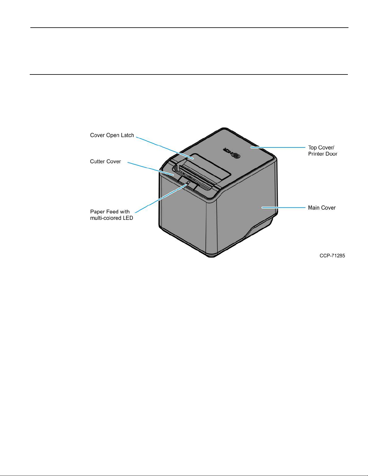
General Description
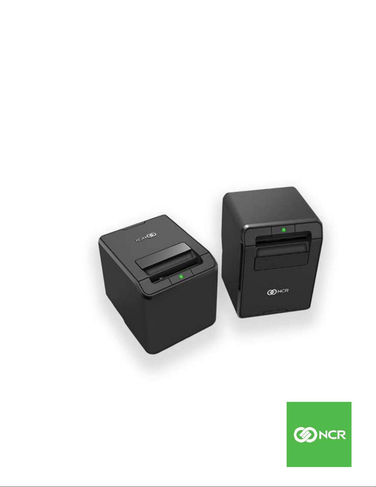
The NCR RealPOS 7199 Thermal Receipt Station Printer delivers high–performance
receipt printing in a compact and flexible solution. This printer provides a solution that
is designed for any environment that requires thermal receipt printing.
The printer’s high–speed thermal printing capability and proven reliability can help
reduce transaction time, increasing customer satisfaction, and throughput. It prints
crisp text, at a rate of 355mm or 14 inches per second, and sharp graphics in 16 levels of
grayscale. The printer can be wall mounted, integrated with an NCR RealPOS terminal,
or placed on the countertop as a front or top exiting receipt printer. It is flexible enough
to meet the customer’s changing needs or space constraints.
The printer can be connected to any host computer that uses USB communication
interface. The printer is also available with RS–232C or LAN communication interface.

1-2 NCR RealPOS 7199 Thermal Receipt Station Printer
Features and Options
The 7199 Thermal Receipt Station Printer comes with the proven features and
functionality of the 7197 along with several new features and options that enhance the
printer’s performance, serviceability, reliability, and versatility.
General Features
• Thermal printing
• Resident bar codes
• Code 39
• Code 128
• UPS–A
• UPC–E
• JAN8 (EAN)
• JAN13 (EAN)
• Interleaved 2 of 5
• Code–bar
• PDF417
• GS1 DataBar
• QR
• Drop–in paper loading
• Paper Jam Sensor (detecting initial jam of paper at platen roller)
• Paper exhaust indicator
• Support Vertical/ Wall mount (90 Deg)
• Paper low sensing: adjustable through firmware for 40ft, 30ft, 20ft and 10ft
• Black mark sensor as factory option
• 19 resident character language Code Pages:
• PC Code Page 437 (US English)
• PC Code Page 850 (Multilingual)
• PC Code Page 852 (Slavic)
• PC Code Page 858 (with Euo symbol)
• PC Code Page 862 (Hebrew)
• PC Code Page 863 (French Canadian)
• PC Code Page 864 (Arabic)

NCR RealPOS 7199 Thermal Receipt Station Printer 1-3
• PC Code Page 865 (Nordic)
• PC Code Page 866 (Cyrillic)
• PC Code Page 1252 (Windows Latin #1)
• PC Code Page 1256 (Arabic) – Contextual
• PC Code Page 1256 (Arabic) – Fixed
• PC Code Page Hungary
• PC Code Page Katakana
• PC Code Page 874 (Enhanced Thai)
• PC Code Page 932 (Windows–31J)
• PC Code Page 936 (Simplified Chinese)
• PC Code Page 949 (Korean)
• PC Code Page 950 (Mainland China)
• Unicode support (UTF–16)
• Auto knife cut
• Cover open sensors
• Industry standard USB communication interface
• Variant of Print Mode: High speed print mode, High quality print mode and Eco
print mode
• Thermal Head Failure Detection
• One cash drawer connector (supports 2 cash drawers)
• Top and front exit receipt
• Multi–color LED
• Watermark and grayscale support
Note: The 7199 Thermal Receipt Station Printer does not use a paper journal.

1-4 NCR RealPOS 7199 Thermal Receipt Station Printer
Thermal Print Head
The 7199 Thermal Receipt Station Printer uses a thermal print head for printing receipts.
It is extremely fast and quiet. Because it uses heat to print directly on paper, there is no
cassette or ribbon to change, eliminating soiled fingers and paper dust.
The print head does not need to be regularly cleaned and no regularly scheduled
maintenance is required if the recommended paper is used. For more information, refer
to Ordering Thermal Receipt Paper on the facing page.
If you notice spotty or light print, the thermal head could be dirty. Wipe the head with
cotton swabs and rubbing alcohol. If spotty or light printing problems persist after the
thermal print head has been cleaned, the print head could be damaged beyond repair.
The print head is designed to have a long life span, but it can be replaced overtime if
needed. Only a trained service representative may replace the print head.

NCR RealPOS 7199 Thermal Receipt Station Printer 5
Ordering Paper and Supplies
Ordering Thermal Receipt Paper
The 7199 Thermal Receipt Station Printer requires NCR qualified thermal paper to be
used on the thermal receipt print station to ensure proper operation of the printer. In
addition, the paper rolls must have these dimensions.
Diameter Length Width
80 mm Max
(3.12 in Max)
80 mm Max.
(3.12 in Max.)
The paper must not be attached at the core. If the paper is attached to the paper core,
the print head may be damaged when the paper is exhausted.
273 ft 80 mm +0.5mm/–1.2mm
(3.15in +0.020in/0.047in)
273 ft 58mm +0mm/–1.0mm
(2.28in +0in/0.039in)
Paper grades available from Iconex
Paper
Stock
856911 Economy (for text printing)
856966 Standard Sensitivity (for text and simple graphics)
878559 High Sensitivity (for text, bar codes & detailed graphics)
856380 For improved achievability and added resistance to incompatible
Paper Grade Description
substances.
856461 Red/Black
856458 Blue/Black
To order thermal receipt paper, contact your sales representative or order from NCR at
the following toll free number:
Iconex
Media Products Division
Voice: 1(800)543-8130 (toll free),
or local listing of Media Products sales office
6 NCR RealPOS 7199 Thermal Receipt Station Printer
Other Supplies
Contact your sales representative to order the supplies listed in the following table.
Item Type Alias Number
External Power Supply 75W External Power
Supply, No Power Cord
75W External Power
Supply with US Power
Cord
60W External Power
Supply
AC Cables for External
Power Supply
Non-Powered RS-232
US Power Cord 1416-C325-0030
UK Power Cord 1416-C321-0030
SEV Power Cord 1416-C320-0030
Australian Power Cord 1416-C322-0030
International Power Cord 1416-C323-0030
Argentina Power Cord 1416-C009-0018
1.0 meter 1416-C879-0010
7167-K511
7167-K510
7197-K510
(Serial) Interface
Non-Powered USB Cable 1.0 meter 1432-C083-0010
Powered USB Cable 24V Powered USB Cable,
Power Only USB Cable
for Serial Configuration
4.0 meters 1416-C879-0040
4.0 meters 1432-C083-0040
1432-C086-0010
1.0 meter, Black
24V Powered USB Cable,
4.0 meters, Black
1.0 meter 1432-C092-0010
4.0 meters 1432-C092-0040
1432-C402-0040

NCR RealPOS 7199 Thermal Receipt Station Printer 7
Item Type Alias Number
Cash Drawer Cable 1.8 meters 1639-K044
1639-K043
1639-K213
0.6 meter (Y-Cable) 1416-C372-0006
1639-K045
Narrow 58mm Width
Release 1.0 7199-K058
Paper Guide
Ethernet Cable 8–wire 1432-C046-0030
Integrated Terminal Filler
7607-K324
Plate
Rear Cable Cover 7199-K200
Under Counter Mounting
7199-K100
Bracket
Serial Interface Module 7199-K001
Ethernet Interface
7199-K002
Module
8 NCR RealPOS 7199 Thermal Receipt Station Printer
What is in the Box
The following items are packed in the shipping box:
• Printer enclosed in a plastic bag and foam pack
These items may be ordered as options from NCR:
• Communication cable (from host computer to printer)
• Cash drawer cables
These cables may be ordered from other equipment suppliers. For more information,
refer to Ordering Paper and Supplies on page5.
• DC Power cable
• External Power Supply
• USB plus Power cables
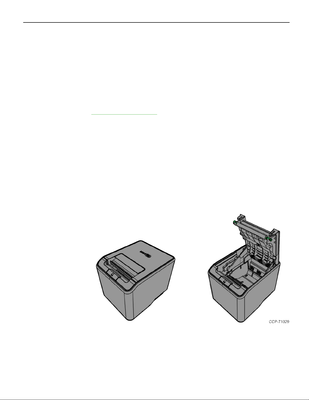
Removing the Packing Material
To remove the packing material, follow these steps:
1. Remove the printer from the foam pack.
2. Remove the plastic bag from the printer.
3. Save all packing materials for future storing, moving, or shipping of the printer.

NCR RealPOS 7199 Thermal Receipt Station Printer 9
Repacking the Printer
To repack the printer, follow these steps:
1. Place the printer in the plastic bag and in the foam pack.
2. Place the packed printer in the box.
3. Secure the box with packing tape.

10 NCR RealPOS 7199 Thermal Receipt Station Printer
Cleaning the Printer
Cleaning the Cabinet
The external cabinet materials and finish are durable and resistant to these items:
• Cleaning solutions
• Lubricants
• Fuels
• Cooking oils
• Ultraviolet light
The 7199 Thermal Receipt Station Printer does not require a scheduled maintenance.
Clean the cabinet as needed to remove dust and finger prints. Use any household
cleaner designed for plastics, but test it first on a small unseen area. If the receipt bucket
is dirty, wipe it with a clean, damp cloth.
Cleaning the Thermal Print Head
Caution: Do not spray or try to clean the thermal print head or the inside of the printer
with any kind of cleaner as this may damage the thermal print head and electronics.
If the thermal print head appears dirty, wipe it with cotton swabs and isopropyl alcohol.
If spotty or light printing problems persist after the thermal print head has been cleaned,
refer to Troubleshooting Problems on page27.
Note: The thermal print head does not normally require cleaning if the recommended
paper grades are used. If non–recommended paper has been used for an extended
period of time, cleaning the print head with cotton swabs and rubbing alcohol will not
be of much benefit. For more information on the recommended paper, refer to Ordering
Paper and Supplies on page5.
NCR RealPOS 7199 Thermal Receipt Station Printer 11
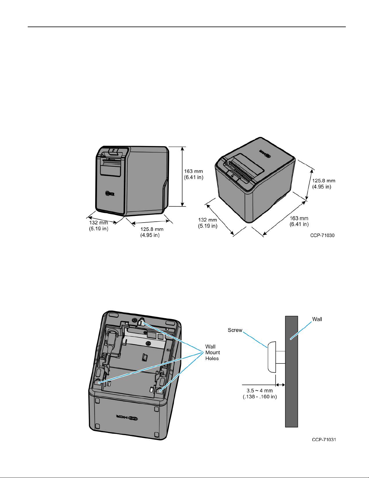
Choosing a Location
Normal Table Top
The 7199 Thermal Receipt Station Printer takes up a relatively small counter space and
may be set on or near the host computer. Make sure there is enough room to open the
receipt cover to change the paper. The following illustration shows the actual
dimensions of the printer, but leave several inches around the printer for connecting
and accessing the cables.
Wall Mounted
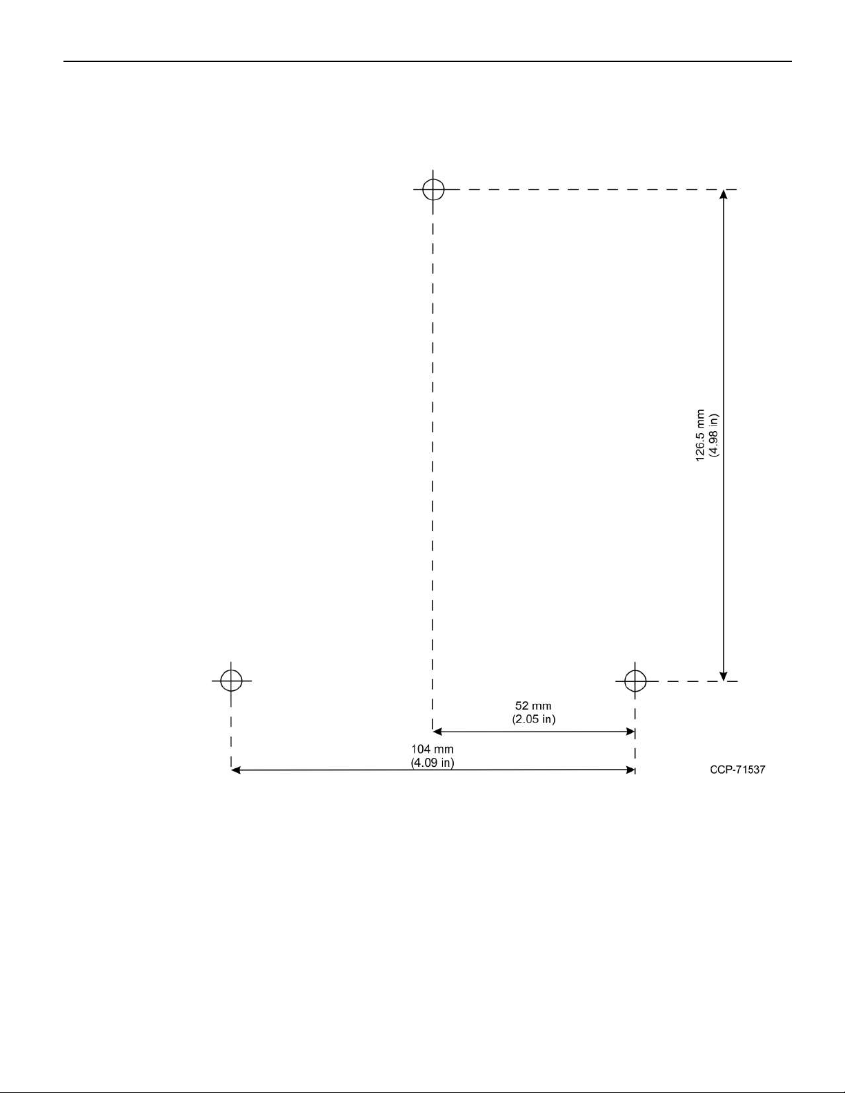
The 7199 Thermal Receipt Station Printer may be mounted on a vertical wall. Make sure
there is enough room to open the receipt cover to change the paper. Mount the screws
on the wall using the following recommended mount dimensions. Use a #8 wood screw,
which is to be securely fastened to a wall stud, or use a “Molly” fastener (not provided).
12 NCR RealPOS 7199 Thermal Receipt Station Printer
Print the following template to use as a guide for the wall screw position.
 Loading...