

Page 1
NCR RealPOS 70XRT (7403)
POS Workstation
Release 1.0
User Guide
B005-0000-1872
Issue A
Page 2

The product described in this book is a licensed product of NCR Corporation.
NCR is a registered trademark of NCR Corporation.
NCR RealPOS is either a registered trademark or a trademark of NCR Corporation in the United States and/or other countries.
UniWinDriver, TSHARC and Hampshire are trade names of Hampshire Company, Inc. Copyright 1995 - 2008 Hampshire Company, Inc.
It is the policy of NCR Corporation (NCR) to improve products as new technology, components, software, and firmware become available.
NCR, therefore, reserves the right to change specifications without prior notice.
All features, functions, and operations described herein may not be marketed by NCR in all parts of the world. In some instances,
photographs are of equipment prototypes. Therefore, before using this document, consult with your NCR representative or NCR office for
information that is applicable and current.
To maintain the quality of our publications, we need your comments on the accuracy, clarity, organization, and value of this book.
Address correspondence to:
Manger, Information Products
NCR Corporation
2651 Satellite Blvd.
Duluth, GA 30096
Or send feedback:
http://www.info.ncr.com/eFeedback.cfm
Copyright © 2008
By NCR Corporation
Dayton, Ohio U.S.A.
All Rights Reserved
Page 3

i
Preface
Audience
This book is written for hardware installer/service personnel, system integrators, and field
engineers.
Notice: This document is NCR proprietary information and is not to be disclosed or
reproduced without consent.
Safety Requirements
The NCR RealPOS 70XRT conforms to all applicable legal requirements. To view the
compliance statements see the NCR RealPOS Terminals Safety and Regulatory Statements
(B005-0000-1589).
The on/off switch is a logic switch only. The AC line voltage primaries are live at all times
when the power cord is connected. Therefore, disconnect the AC power cord before opening
the unit to install features or service this terminal.
Page 4

ii
References
• NCR RealPOS 70XRT Site Preparation Guide (B005-0000-1873)
• NCR RealPOS 70
• NCR RealPOS 70
XRT Hardware Service Guide (B005-0000-1874)
XRT Parts Identification Manual (B005-0000-1875)
• NCR Retail Systems Manager Software User's Guide (B005-0000-1518)
Page 5

iii
Table of Contents
Chapter 1: Overview
Introduction ...............................................................................................................1-1
Model Numbers.........................................................................................................1-1
Terminal Dimensions and Weights ...........................................................................1-1
Optional Configurations............................................................................................1-2
Model and Serial Number Labels.............................................................................. 1-3
Features .....................................................................................................................1-4
Motherboard .......................................................................................................1-5
Cabinet................................................................................................................1-7
Storage Media.....................................................................................................1-7
Operating Systems .............................................................................................. 1-7
MSR....................................................................................................................1-7
I/O Board...................................................................................................................1-8
I/O Board Connectors .........................................................................................1-8
Powered Serial Port Jumper Settings..................................................................1-9
Removing the Display Head from the Base ............................................................1-11
Integrated Customer Displays .................................................................................1-13
Remote Customer Displays ..................................................................................... 1-15
NCR 5975 2x20 VFD Customer Display .........................................................1-15
Features ........................................................................................................1-15
Character Sets...............................................................................................1-16
NCR 5975 Graphical VFD Customer Display..................................................1-17
Hardware Features........................................................................................ 1-17
Character Sets...............................................................................................1-18
Software Features ......................................................................................... 1-19
5942 12.1-Inch Color LCD...............................................................................1-20
5942 15-Inch Color LCD..................................................................................1-20
5964 15-Inch Touch Screen..............................................................................1-21
5964 15-Inch Touch Screen..............................................................................1-22
Features ........................................................................................................1-22
Power Supply ..........................................................................................................1-23
AC Input ...........................................................................................................1-23
DC Outputs .......................................................................................................1-23
Maximum Rated Output Power ........................................................................1-23
Printers ....................................................................................................................1-24
NCR 7167 Printer ............................................................................................. 1-24
NCR 7198 Printer ............................................................................................. 1-24
NCR 7168 Printer ............................................................................................. 1-25
Page 6

iv
Power Management.................................................................................................1-26
G3 Mechanical Off ...........................................................................................1-26
G2/S5 Soft Off..................................................................................................1-26
G1 Sleeping ......................................................................................................1-26
G0 Working ...................................................................................................... 1-26
ACPI Sleep States (S0 – S5).............................................................................1-26
Wake on LAN .........................................................................................................1-28
Chapter 2: Installing the Terminal
Introduction ...............................................................................................................2-1
Installation Summary ................................................................................................2-2
Installation Restrictions.............................................................................................2-2
Connecting the External Cables ................................................................................2-3
Accessing the I/O Panel......................................................................................2-4
Accessing the Backplane Connectors ................................................................. 2-6
AC Power Cord Connector ................................................................................. 2-6
Cable Routing............................................................................................................ 2-7
I/O Board Cable Routing ....................................................................................2-7
Terminal Configured with a DVD-ROM Drive ............................................. 2-8
Terminal without a DVD-ROM Drive ...........................................................2-9
Backplane Cable Routing .................................................................................2-11
Removing the Storage Media .................................................................................. 2-12
Powering Up the Terminal ......................................................................................2-13
Terminal On/Off Switch ...................................................................................2-13
Power Button Override.................................................................................2-13
Default Boot Order ...........................................................................................2-13
Keyboard support.............................................................................................. 2-14
Connecting peripherals .....................................................................................2-14
Calibrating the Touch Screen ...........................................................................2-14
Out-of-Box Failures ................................................................................................2-15
Chapter 3: Touch Screen Calibration
Installing and Calibrating the Touch Screen .............................................................3-1
Installing the Driver............................................................................................3-1
Calibrating the Touch Screen .............................................................................3-3
Verifying the Calibration .................................................................................... 3-6
Optional Settings ................................................................................................3-8
Chapter 4: Installing a Secondary (Dual) Display
Configuring the Graphics Controller......................................................................... 4-1
Configuring the Graphics Controller......................................................................... 4-2
Page 7

v
Single Display Mode Setup ................................................................................4-2
Dual Display Clone Setup (Notebook and Monitor) ..........................................4-3
Extended Desktop Dual Display Setup (Notebook and Monitor).......................4-4
Intel Graphics Controller Hot Keys ....................................................................4-5
Chapter 5: Configuring AMT
Configuring the 7403 Terminal.................................................................................5-1
Logging onto the 7403 Terminal Using AMT ..........................................................5-9
Removing the Hard Disks .......................................................................................5-10
Chapter 6: Installing Optional Remote Peripherals
Introduction ...............................................................................................................6-1
Cable Routing .....................................................................................................6-1
Installing a Transaction Printer .................................................................................6-1
USB Installation..................................................................................................6-2
RS-232 Installation w/Power from Powered USB..............................................6-3
Installing a Remote Customer Display...................................................................... 6-4
NCR 5964 15-inch Touch LCD Cable Connections...........................................6-6
NCR 5942 12.1-Inch LCD Monitor Cable Connections.....................................6-9
NCR 5942 15-Inch LCD Monitor Cable Connections .....................................6-12
NCR 5965 15-Inch Touch LCD Cable Connections ........................................6-14
Installing an NCR 5975 Remote Customer Display ......................................... 6-17
Installing a Cash Drawer .........................................................................................6-21
Installing a Second Cash Drawer......................................................................6-22
Chapter 7: Installing a RAID System
The Intel Matrix Storage Manager (RAID)............................................................... 7-1
Installing a RAID System ................................................................................... 7-1
Replacing a Failed RAID 1 (Mirrored) HDD ..................................................... 7-7
RAID Option ROM ............................................................................................7-8
Chapter 8: 2x20 Customer Display Interface
Introduction ...............................................................................................................8-1
General Specifications...............................................................................................8-1
Serial Communication Interface................................................................................ 8-1
Command Codes ....................................................................................................... 8-2
User Defined Character Definition (08h, CODE, Byte1…Byte5)......................8-2
Character Table Select (09h, TABLE CODE).................................................... 8-2
Clear Display (12h)............................................................................................. 8-3
Luminance Control (11h, LUMINANCE)..........................................................8-3
Cursor Position (10h, POSITION)......................................................................8-3
Page 8

vi
Reset (13h)..........................................................................................................8-3
Character Tables and Codes ...............................................................................8-3
CP437 .............................................................................................................8-4
CP858 .............................................................................................................8-5
CP866 .............................................................................................................8-6
CP932 .............................................................................................................8-7
Chapter 9: Cash Drawer Interface
Chapter 10: Wedge to USB MSR Software Migration
Overview .................................................................................................................10-1
Software Requirements ...........................................................................................10-2
Potential Operational Differences ........................................................................... 10-3
Deployment Considerations ....................................................................................10-3
Local Update..................................................................................................... 10-3
Remote Deployment .........................................................................................10-3
Chapter 11: Maintenance
Cabinet and Touch Screen Cleaning Procedures.....................................................11-1
Cleaners/Solvents to Use ..................................................................................11-1
Cleaners/Solvents to NOT Use ......................................................................... 11-1
Cooling Vent Cleaning............................................................................................11-2
MSR Cleaning Procedures ......................................................................................11-3
Chapter 12: Operating System Recovery
Introduction .............................................................................................................12-1
Prerequisites...................................................................................................... 12-1
Connecting an External CD-ROM Drive ................................................................12-2
OS Recovery Procedures.........................................................................................12-3
Chapter 13: BIOS Updating Procedures
Introduction .............................................................................................................13-1
Prerequisites...................................................................................................... 13-1
Creating the Bootable Media................................................................................... 13-2
Creating a Bootable CD....................................................................................13-2
Creating a Bootable USB Memory Drive.........................................................13-2
SPI/BIOS Updating Procedures ..............................................................................13-3
Chapter 14: BIOS Settings
Entering Setup ......................................................................................................... 14-1
How to Select Menu Options ..................................................................................14-1
Page 9

vii
Restoring Factory Settings ......................................................................................14-1
BIOS Default Values............................................................................................... 14-2
Main Menu........................................................................................................14-2
Advanced Menu................................................................................................14-2
PCI/PnP Menu .................................................................................................. 14-5
Boot Menu ........................................................................................................ 14-6
Security Menu................................................................................................... 14-6
Chipset Menu....................................................................................................14-7
Appendix A: Memory Map
DOS Considerations ..........................................................................................A-1
Appendix B: IRQ Settings
Interrupts............................................................................................................ B-1
Default Settings ............................................................................................. B-1
Page 10

viii
Revision Record
Issue Date Remarks
A Nov 2008 First issue
Page 11

Chapter 1: Overview
Introduction
TheNCRRealPOS70XRT(alsoreferredtoasNCR7403)isthelatestinscalable,retail‐
hardenedIntegratedPoint‐of‐Sale.TheNCRRealPOS70
intuitivecapacitivetouchscreeninterfaceplusavarietyofretailconsumerinterfaces.
Theproductisdesignedforextendedlifecycles,stabilityandsuperioravailability.
Theterminalhasbeenenhancedtoofferevenbetterserviceabilityandscalabilitythan
previousgenerations.Engineeredtothriveinthemostdemanding
NCRRealPOS70
MerchandiseaPOSplatformthatoffersexceptionalvaluefortheirPOSinvestment.
XRTcontinuestoofferan
environments,the
XRToffersretailersinHospitality,ConvenienceStores,andGeneral
Model Numbers
Major Model Description
7403-1000 Intel Celeron processor, 1GB DDR2, No Hard Disk, US Power Cord
7403-1001 Intel Celeron processor, 512MB DDR2, 80GB or larger Hard Disk, US Power Cord
7403-1300 Intel Core2 Duo T7500 processor, 2GB DDR2, No Hard Disk, US Power Cord
7403-0015 LCD Touch Display, 15”, Capacitive
Terminal Dimensions and Weights
See the NCR RealPOS 70XRT Site Preparation Guide, B005-0000-1464.
Page 12
1-2 Chapter 1: Overview
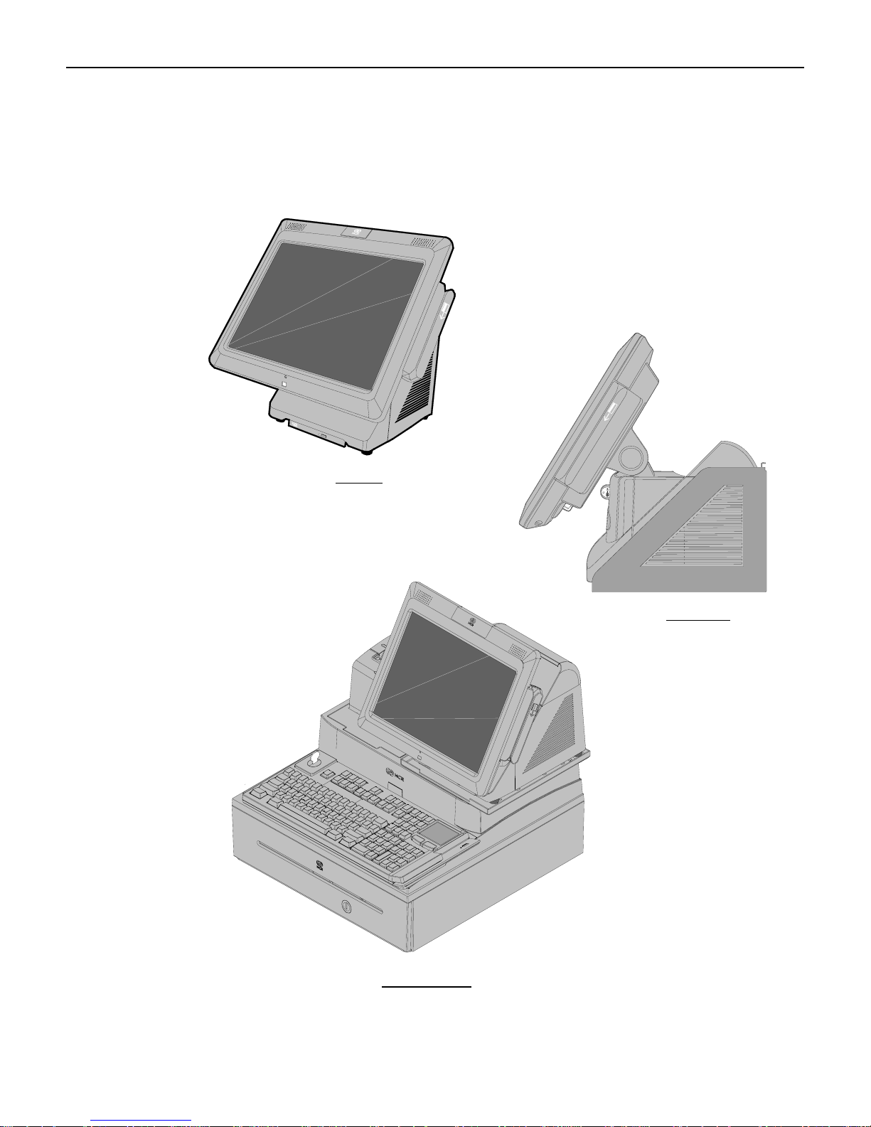
Optional Configurations
The NCR RealPOS 70XRT can be a free standing desktop, wall mounted, or it can be combined
with a integration tray to add further value and save valuable counter space. The integration
tray supports a variety of NCR’s most popular peripheral options.
Desktop
Wall Mount
26346
Integration Tray
Page 13
Chapter 1: Overview 1-3
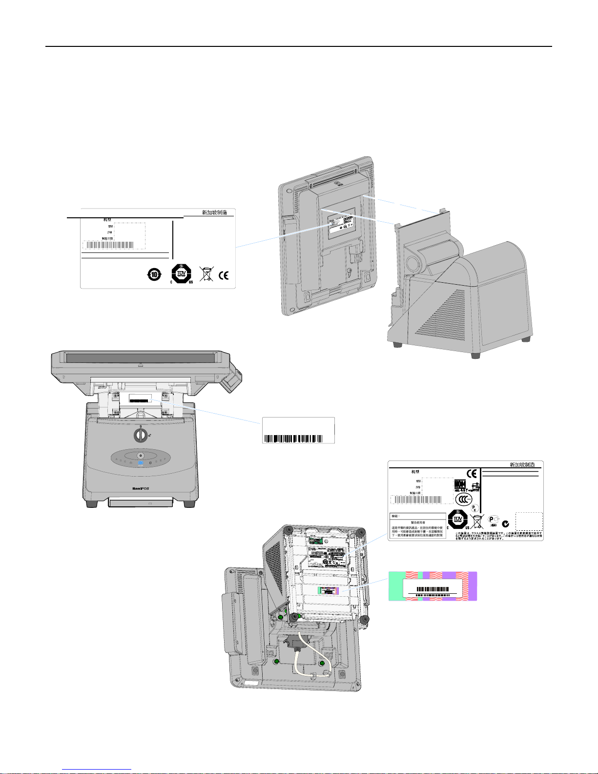
Model and Serial Number Labels
The serial number and model number labels located on the back of the Display Head, on the
top back edge of the Display Head, and on the bottom of the Base. If the terminal was shipped
with an Operating System pre-installed then there is also a Certificate of Authenticity label on
the bottom of the Base.
NCR Corporation
7403 Display Certification Label
Class 7403
Date of Mfg.
Model No
Serial No
Duluth, GA 30096
: XXXX-XXXX
: XX-XXXXXXXX
:
YYYY/ MM/ DD
Made in Singapore
This device compli es with Part 15 of the FCC rules.
Operation is subject to the following two conditions:
(1) this device may not cause harmful interference,and
(2) this device must accept any interference received,
including interference that may cause undesired
operation.
This Class A digital apparatus complies with
Canadian ICES-003.
Lamps contain Mercury. Dispose of Properly.
e
f
a
S
e
t
Class/Model:
S/N:
Cet appareil numerique de la classe A est
conforme a la norme NMB-003 du Canada.
P
r
o
m
d
y
t
o
u
n
c
d
i
t
t
i
e
o
o
t
r
n
s
e
d
NRTL
Class/Model:
S/N:
NCR Corporation
Class 7403
Date of Mfg.
Model No
Serial No
Duluth, GA 30096
: XXXX-XXXX
: XX-XXXXXXXX
: YYYY/ MM/ DD
Made in Singapore
S
P
r
o
m
d
y
t
o
u
e
n
c
f
d
i
t
t
i
a
e
o
o
t
S
r
n
s
e
e
d
t
NRTL
100-120 Vac 2.0 A 50-60 Hz
200-240 Vac 1.0 A 50-60 Hz
This device complies with Part 15 of the FCC rules.
Operation is subject to the following two conditions:
(1) this device may not cause harmful interference,and
(2) this device must accept any interference received,
including interference that may cause undesired
operation.
This Class A digital apparatus complies with
Canadian ICES-003.
Cet appareil numerique de la classe A est
conforme a la norme NMB-003 du Canada.
ACN 000 003 592
150 W
150 W
MIC Label
VCCI-A
Note: Label will be located under the DVD
Drive, if present.
Windows 2000 Pro Embedded 1-2 CPU
ty
i
c
ti
n
e
h
Product Key:
t
u
H95X7-83WVV-CFCWW-M4MXX7-X6XGM
A
f
o
e
t
a
c
i
00019-068-654-234
if
t
r
e
C
26275
Page 14

1-4 Chapter 1: Overview
Features
• Serial ATA (SATA) Hard Drive Interface
• High-speed Gigabit Ethernet
• Intel AMT 4.0 Remote Management
• Proven Capacitive Touch Technology
• High Brightness 15” LCD
• Stereo Speakers
• Motion Detection Sensor
• 0 – 90 Degree Display Tilt
• 2x20 VFD Customer Display
• Dual Cash Drawer Support
– Single Connector for Backwards Compatibility
– Connected through a cash drawer Kickout connector on the I/O Board or through the
cash drawer Kickout connector on the transaction printer.
– The terminal can be configured with 0, 1, or 2 cash drawers. The first drawer is
attached to the terminal through a cable with an RJ-45 connector. A second drawer can
be connected using a ‘Y’ cable.
Note: A single Open/Close status signal is shared with both drawers. Therefore, it is
not possible to determine which cash drawer is open.
• Four Powered Serial Ports (I/O Board)
• Powered Serial Port to Support an Integrated Customer Display (Backplane Board)
• Two 12V USB+Power Ports (I/O Board)
• One 24V USB+Power port (I/O Board)
• Six Type-A USB Connectors (4 on I/O Board, 1 on Backplane, 1 in Display Head)
• MIC Input (I/O Board)
• Audio Out (I/O Board)
• VGA Connector (Backplane Board)
• Combination Power/Audio Line Out Port to Support Customer Displays (Backplane)
• Speed Controlled CPU Fan
• Integrated Signage System
Page 15

Chapter 1: Overview 1-5
• Modules Plug into a Backplane Board
– Front Accessibility
– Eliminates Most Internal Cables
– Simplifies Upgrades
– Faster On-Site Service
– Efficient Depot and Self-Service Options
• Removable Display Head
• Power Supply
– 265W Output Power
– Custom ATX12V Power Supply
– 80+ Certified
– Modular and Serviceable w/o Disconnection of any Cables
– Supports NCR Printers Running in 75W Mode
Motherboard
• Mobile Intel® GM 45 Express Chipset
• Intel® Processors
– Intel® Core™2 Duo T7500
– Intel® Celeron® 575
• Two SODIMM Sockets Supporting 667 – 800 MHz DDR2 Memory Modules
– 512MB – 4GB
– Dual Channel Support
• Intel Cantiga-GM Chipset
– Intel Cantiga-GM Graphics Memory Controller Hub (GMCH)
– Intel ICH9M I/O Controller Hub
• IO connections are through a backplane board except for devices plugging directly into
motherboard. Another IO Connector row is located on a separate I/O Board.
• Video – Intel integrated graphics subsystem (Gen 5.0 Core, 457MHz) with dual display
support
– LVDS LCD supporting dual channel 24 bit panels including DDC signals and
backlight control
– VGA (analog) including DDC
Page 16

1-6 Chapter 1: Overview
• Audio – Intel High Definition Audio and HD Codec driving/receiving these interfaces
from the backplane (Jack detect support on all ports)
– Speaker out L/R with 3W/channel amplifier on motherboard.
– Headphone out (port can be re-tasked using HD audio)
– MIC in (port can be re-tasked using HD audio)
– Additional audio out port (for future use)
• LPC Bus
– LPC driven onto backplane to interface SuperIO or other LPC devices elsewhere in the
system
• USB
– Support for High Speed USB devices, support for USB port disable
– All 12 USB ports available on Cantiga are driven into the backplane
– A single over-current signal is received from the backplane.
• PCI Express
– The motherboard drives two PCI Express x1 interfaces into the backplane
• SATA
– Three SATA ports driven onto backplane
– Support for two hard disk drives and one optical disk drive
– Intel Matrix Storage Manager (includes RAID) supported on all ports
• AMT
– Full support for Intel AMT 4.0 including out of band functions
• LAN
– Intel 82567 Platform LAN connect with 10/100/1000 Ethernet support LAN
• BIOS Hardware Support
– BIOS resident in the 32MB SPI Flash device
– Support for ACPI, SMBIOS
• Security
– TPM 1.2 module integrated into ICH9M in chipset
Page 17
Chapter 1: Overview 1-7
Cabinet
• Tool-Free Front Accessible Components
– Motherboard on a Removable Sled
– One or Two SATA Hard Drives
– DVD ROM Drive
– Power Button
• Nine Visible LEDs
– Lighted Logo to Indicate Power On / Suspend Mode
– LAN Link Activity
– Hard Drive Activity
– Six Diagnostic LEDs
Storage Media
• Hard Drive Options
– Single 3.5” Hard Drive
– Dual 2.5” Hard Drives (On-board RAID)
• Slim-line DVD-ROM Drive
• Solid State Drive – SATA interface
Operating Systems
• Windows XP Professional
• POSReady
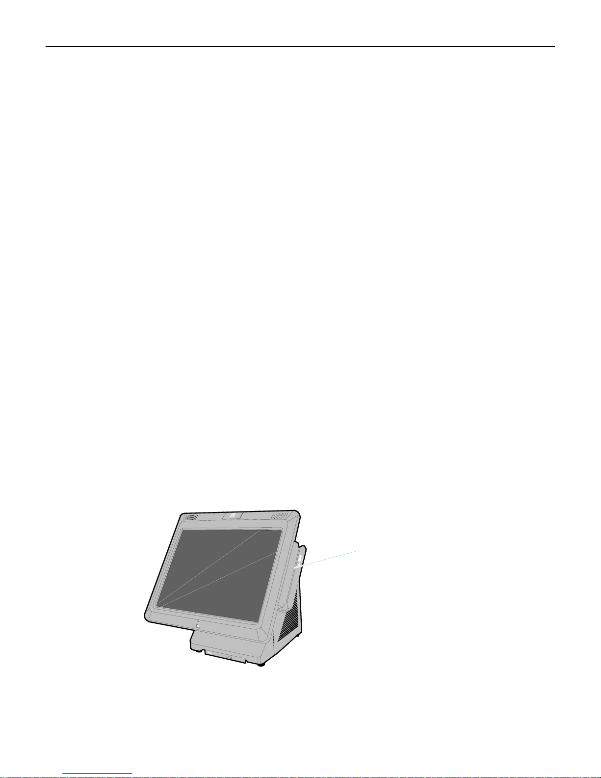
MSR
MSR
The MSR interface supports a maximum of 3 tracks of magnetic stripe information for support
of ISO format cards.
26270
Page 18
1-8 Chapter 1: Overview
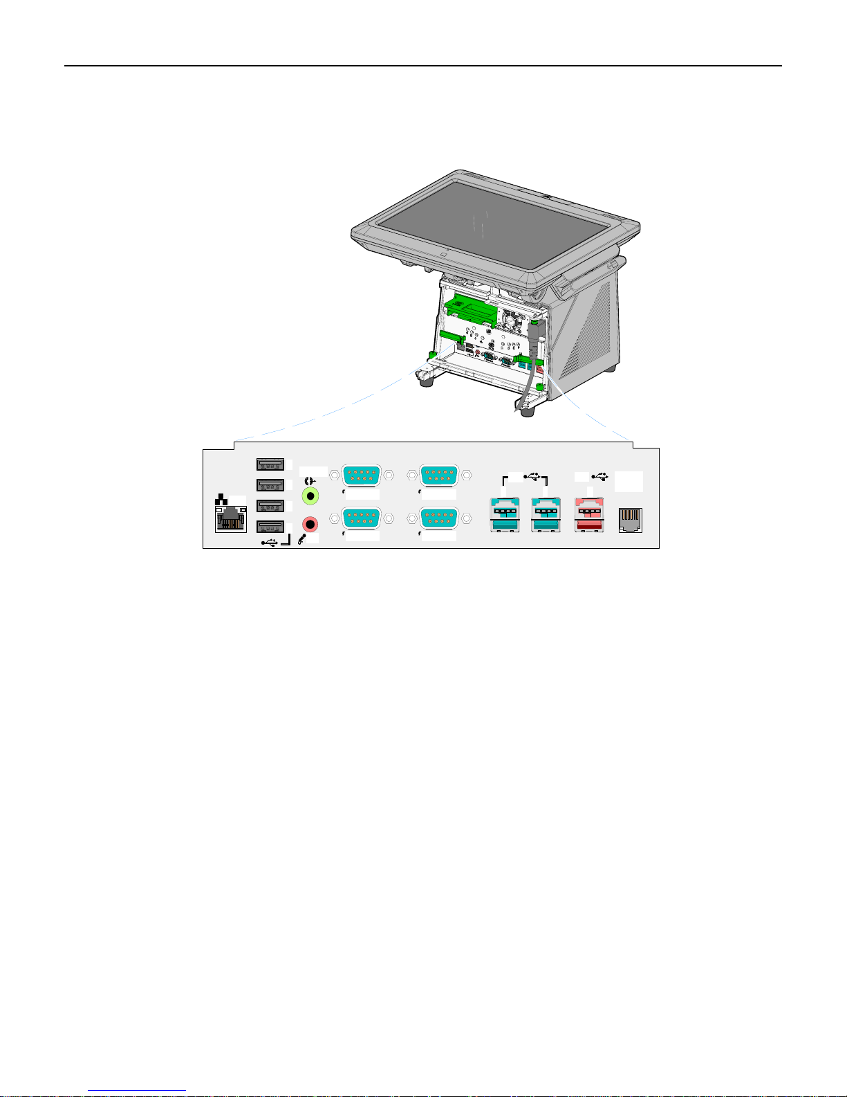
I/O Board
The I/O Board is used to provide external connections to the motherboard. It slides into
position in the terminal underneath the motherboard.
LAN
I/O Board Connectors
• Ethernet
– One 10/100/1000 MDI port
• USB
– Four High Speed Ports. Each port is capable of supplying 5 V at 0.5 A max.
– Two 12 V High Speed USB+Power ports. Each port is capable of supplying 12 V at
– One 24 V High Speed USB+Power ports. The port is capable of supplying 24 V at
• Audio
– Double stack connector for Headphone Out and Mic In
D
C
B
A
Line Out
MIC
12V 24V
RS232/DRS232/C
RS232/BRS232/A
E F G
Cash
Drawer
26297b
Self-healing polyfuses are used to provide current protection.
2.0 A max. Connected peripherals must not exceed this rating. Self-healing polyfuses
are used to provide current protection.
0.5 A continuous and 3.0 A peak. A socketed fuse is used to provide current
protection.
• Serial Ports (4)
– RS-232 ports with selectable power (+5 V, +12 V, or RI) on pin 9. (One RS-232 port
is connected to the backplane and is available on the Backplane Board.)
• Cash drawer Kickout port
– Support for two cash drawers on a single port
Page 19
Chapter 1: Overview 1-9
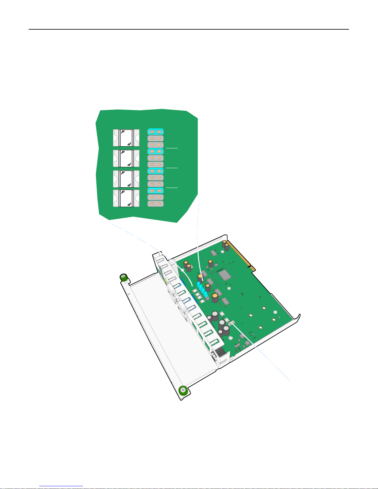
Powered Serial Port Jumper Settings
ThefourserialportshavejumperoptionsforeitherRingIndicator(RI),fused+12V,
orfused+5Vonpin9.Whensettopoweredeachportiscapableofsupportingupto
1.5A(Max.)andisprotectedwithself‐healingpoly‐fuse.Thedefaultsettingforall
portsisRingIndicator.
four
300-15
-
1
5
300-15
-
1
5
300-15
-
1
5
300-15
-
1
5
C
O
M
3
0
0
D
C
O
M
0
0
3
C
RI
12V
5V
RI
12V
5V
C
O
0
0
3
M
B
C
O
M
3
0
0
A
RI
12V
5V
RI
12V
5V
F4, 3 A, 125 V
26226
Page 20
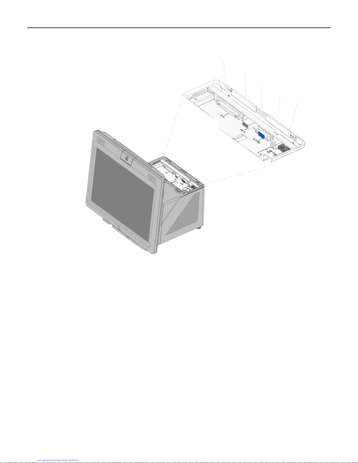
1-10 Chapter 1: Overview
Additional connectors are located under the Customer Display.
Operator Display
USB
VGA
Cust. Display
Power/Audio
(+12 V)
RS-232 (F)
26130
Page 21
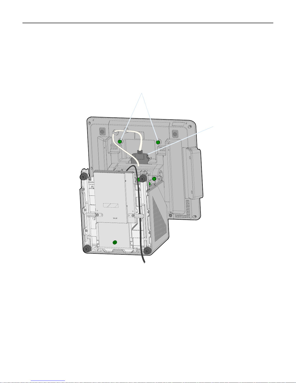
Chapter 1: Overview 1-11
Removing the Display Head from the Base
1. Disconnect the Display Cable
2. Remove the cable from the Cable Guides.
3. Loosen the Display thumbscrews (2).
Display Thumbscrews
Display Cable
26150
Page 22
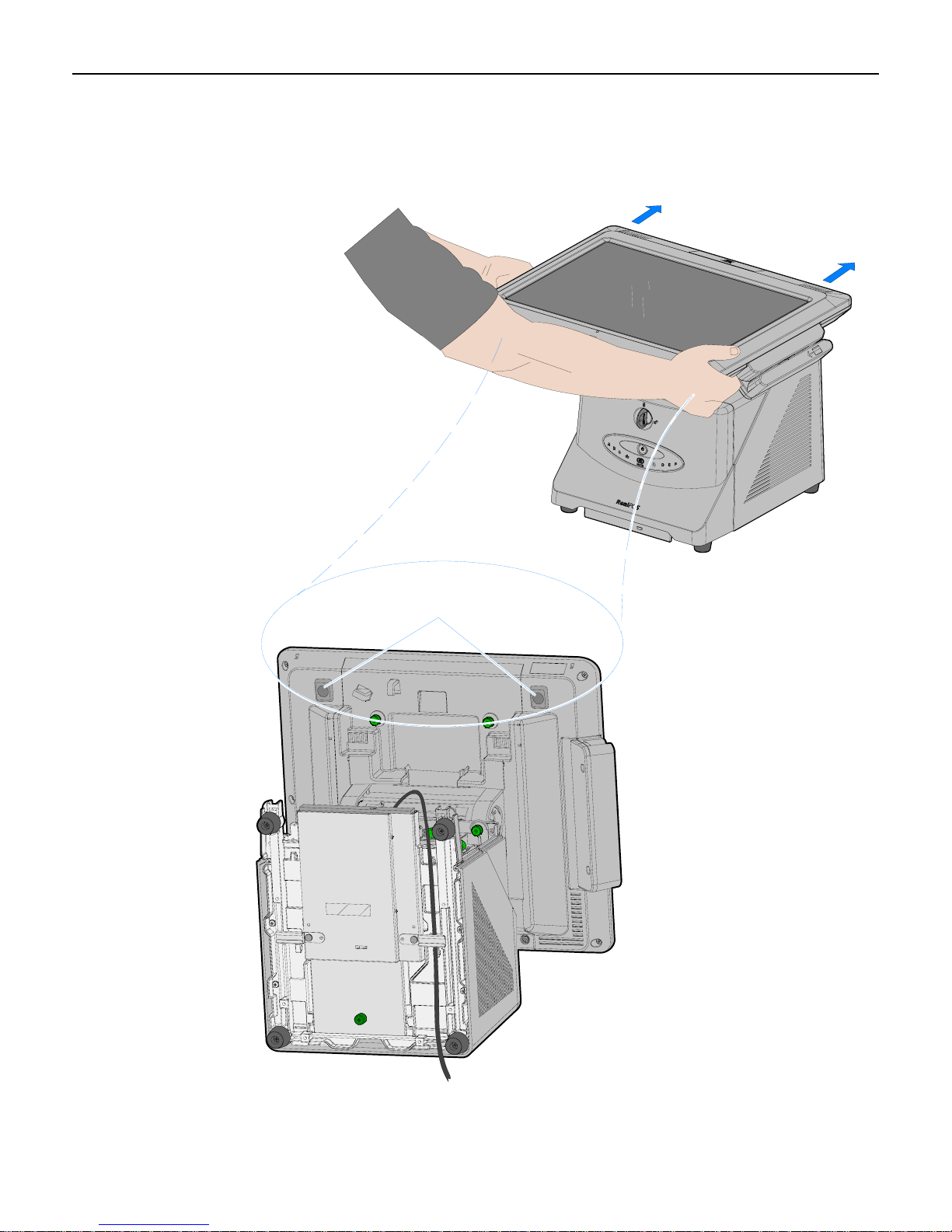
1-12 Chapter 1: Overview
4. Depress the Display Release Latches (2) as you grasp the edges of the display and slide the
Display Head toward the rear of the terminal to disengage it from the chassis.
Display Latches
26151
Page 23

Chapter 1: Overview 1-13
Integrated Customer Displays
The 7403 supports a variety of integrated VFD and LCD customer display.
15"
- 5942 LCD
- 5964 Touch LCD
- 5965 Touch LCD
- 5966 Touch LCD
12.1"
- 5942 LCD
- 5964 Touch LCD
5975 VFD
(2 x 20 or APA)
7403-F451/K451 VFD
(2 x 20)
5982 LCD
(6 1/2")
26339
Page 24
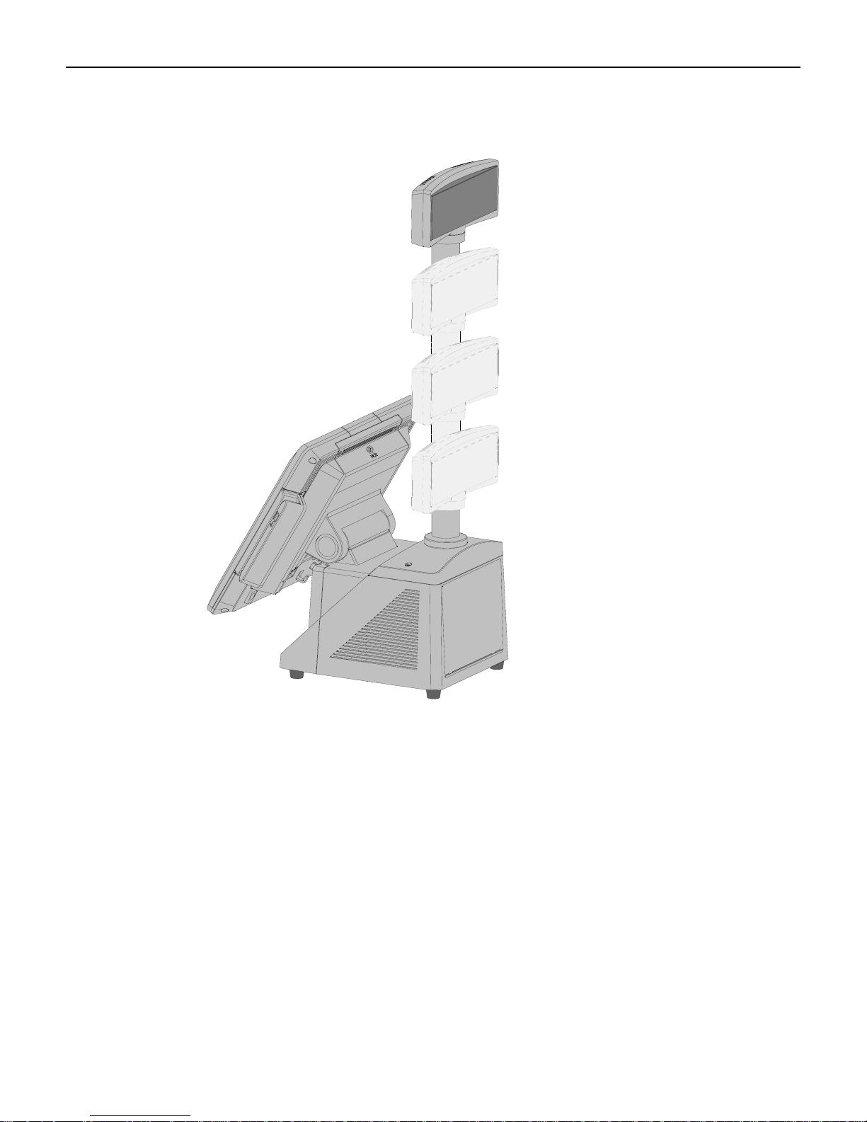
1-14 Chapter 1: Overview
There are four post options for the 5975 display, available in 4 inch increments
26336a
Page 25
Chapter 1: Overview 1-15
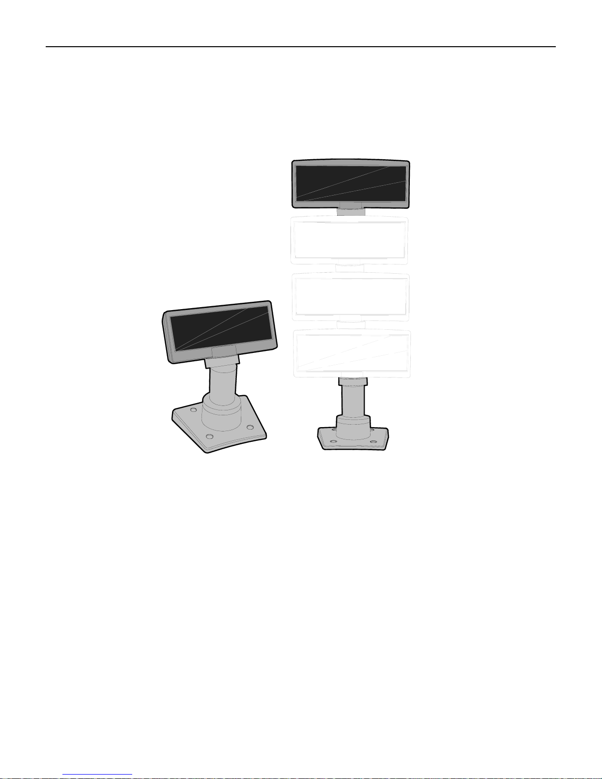
Remote Customer Displays
NCR 5975 2x20 VFD Customer Display
22933
The NCR 5975 Customer Display is designed to be an optional display device for the NCR
retail terminals. It can also serve as a display for any industry-standard PC. It is a Vacuum
Fluorescent Display (VFD).
• 5975-1000 2x20 VFD (G11)
• 5975-1001 2X20 VFD (CG1)
There are four post options, available in 4 inch increments.
Features
• Display
• 2X20 Character Vacuum Fluorescent Display (VFD)
• 7X9 pixel characters
• Character height
• Minimum - 9mm
• Maximum - 11mm
Page 26

1-16 Chapter 1: Overview
• PCB
• Microcontroller
• EIA 232 Interface support
• USB 2.0 Interface support
• Cabinet
• UV Stable Material
• Available in NCR Light Gray (G-11) and NCR Charcoal Gray (CG1)
• Connectors
• 9 pin D sub
• Powered USB
• Cables
• Powered EIA-232
• Powered USB Cable
• Unpowered EIA-232 Cable with Y-Connection for Power Brick
• Unpowered USB Cable with Y-Connection for Power Brick
• 1m and 4m Lengths
• Power Supply
• Universal Power Supply (12V, 12W output)
• 8 pin Molex Connector
• EIA-232 or USB 2.0 I/F support
• The components for both interfaces are populated on a single printed circuit board.
Both interfaces are active, though only one interface can be physically connected at a
time. The display communicates via the interface connected to it.
• Mounting Options
• Table Mount, 4-in. Post
• Table Mount, 8-in. Post
• Table Mount, 12-in. Post
• Table Mount, 16-in. Post
• Integrated Mount for NCR 7456, 7459, 7458
Character Sets
• Support for 19 character sets
• 3 Character sets in base unit
• Code Page 858 (International)
• Katakana
• Code Page 866 (Cyrillic)
• 32 KB Flash Memory for support of up to 16 additional character sets
Page 27
Chapter 1: Overview 1-17
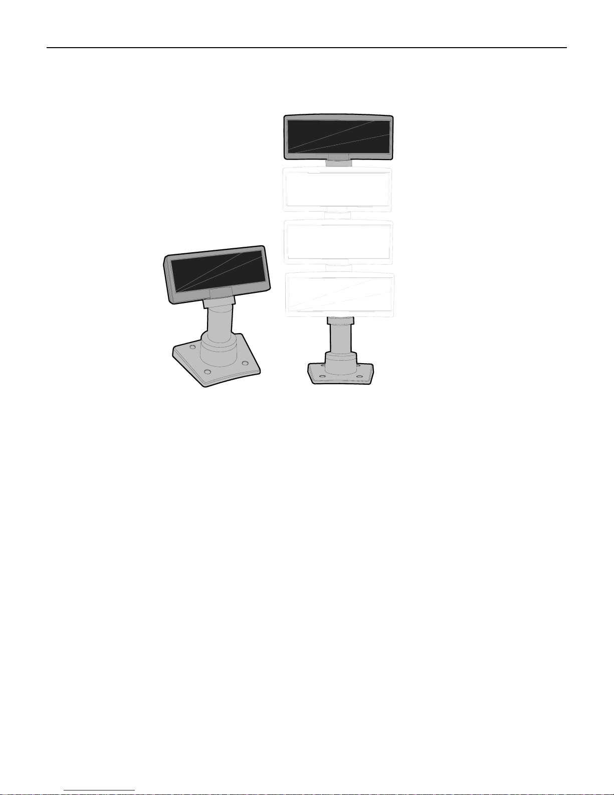
NCR 5975 Graphical VFD Customer Display
22933
The NCR 5975 Customer Display is designed to be an optional display device for the NCR
retail terminals. It can also serve as a display for any industry-standard PC. It is a Vacuum
Fluorescent Display (VFD).
• 5975-2010 Graphical VFD (G11)
• 5975-2011 Graphical VFD (CG1)
Hardware Features
• Display
• 256x64 Graphic Vacuum Fluorescent Display (VFD)
• PCB
• Microcontroller
• EIA 232 Interface support
• USB 1.1 Interface support
• USB 2.0 Interface support
• Cabinet
• UV Stable Material
• Available in NCR Light Gray (G-11) and NCR Charcoal Gray (CG1)
Page 28

1-18 Chapter 1: Overview
• Connectors
• 9 pin D sub
• Powered USB
• Cables
• Powered EIA-232
• Powered USB Cable
• Unpowered EIA-232 Cable with Y-Connection for Power Brick
• Unpowered USB Cable with Y-Connection for Power Brick
• 1m and 4m Lengths
• Power Supply
• Universal Power Supply (12V, 12W output)
• 8 pin Molex Connector
• EIA-232 or USB 1.1/2.0 I/F support
• The components for both interfaces are populated on a single printed circuit board.
Both interfaces are active, though only one interface can be physically connected at a
time. The display communicates via the interface connected to it.
• Mounting Options
• Table Mount, 4-in. Post
• Table Mount, 8-in. Post
• Table Mount, 12-in. Post
• Table Mount, 16-in. Post
• Integrated Mount for NCR 7456, 7467, 7458
Character Sets
• Support for 21 character sets
• 5 Character sets in base unit
• Code Page 858 (International)
• Katakana
• Code Page 866 (Cyrillic)
• 32 KB Flash Memory for support of up to 16 additional character sets
• Weights and Measures support
Page 29

Chapter 1: Overview 1-19
Software Features
• Bi-directional parallel interface
• Five default character sets:
• 16 x 16 or 24 x 24 dots full size JIS 1 and 2 Kanji characters
• 8 x 16 or 12 x 24 dots half size ANK characters
• 5 x 7 dots Katakana characters (Fixed: not downloadable)
• Four downloadable character sets:
• Japanese
• Traditional Chinese
• Simplified Chinese
• Korean-1 (Wansung)
• End User Defined Characters (EUDC)
• 5 x 7 dot characters
• 8 x 16 or 16x16 or 12 x 24 or 24 x 24 dot characters
• Diagnostics
• Micro-controller test
• External memory test
• Display test
Page 30
1-20 Chapter 1: Overview
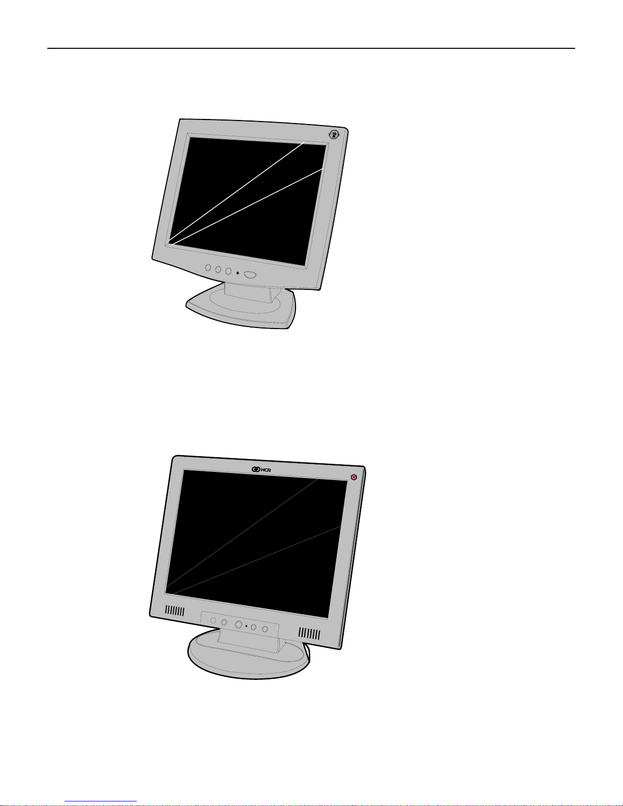
5942 12.1-Inch Color LCD
The 5942 12.1-Inch LCD is designed for customers who desire a color display and prefer the
small footprint and ergonomic packaging of LCD technology versus traditional CRT’s.
Depending on the customer’s requirements, this LCD display can be used either as an operator
display or a customer information display (CID). The 5942 Display features a 12.1-Inch Active
Matrix Color LCD with support for SVGA and XGA resolution.
19809
5942 15-Inch Color LCD
The 5942 15-Inch LCD features a high brightness dual-backlight active matrix LCD with
analog interface which plugs directly into the standard VGA (CRT) port on the RealPOS
80
XRT terminal. It includes a 1.5 meter VGA cable and built-in power supply with standard
IEC AC power connector. The mount and power cable must be ordered separately.
21492
Page 31

Chapter 1: Overview 1-21
5964 15-Inch Touch Screen
22041
The NCR 5964-7xxx is a 15-inch XGA (1024x768) Liquid Crystal Display with either a
resistive or capacitive Touch Screen for operator input.
Features
• 15’ LCD XGA (1024x768) native resolution, 350 nit typical brightness (also supports
VGA, SVGA, SXGA)
• Dual Bulb, adjustable brightness
• Capacitive or 5-wire resistive touch options, USB interface.
• Video - VGA, standard 15 pin female.
• Integrated stereo speakers-volume controlled via the OSD.
• One standard USB port in addition to the powered USB port.
• Optional MSR- field installable, USB interface.
• ACPI and VESA DPM compliance
• Choice of integrated or remote mounts
Page 32

1-22 Chapter 1: Overview
5964 15-Inch Touch Screen
The NCR 5965 is a 15-inch TFT Liquid Crystal Display with a capacitive Touch Screen. The
display accepts industry-standard RGB video images from a PC motherboard and dynamically
resizes VGA (640 × 480), SVGA (800 × 600), XGA (1024 × 768) & SXGA (1280 x 1024) @
60Hz images to fill the entire viewable area.
25819
Features
• Display size - 15” (diagonal)
• LCD Technology - TFT
• Native Format - XGA (1024 × 768) resolution
• Pixel Configuration - RGB vertical stripe
• Supported Colors - 16.2 Million (6 bits + FRC)
• Display text modes supported - SVGA (800 × 600 pixel), XGA (1024 × 768 pixel), VGA
(640 × 480 pixel) & SXGA (1280 x 1024) images to full screen size.
• Moisture & dust sealed display (between touchscreen & display) – NEMA 12/IP54
• OSD controls to allow display adjustments
• Auto selection DC voltage input to allow connection of 12V or 24v option.
• VGA Interface
• DVI Interface
• Three standard USB-A ports (downstream)
• One mini USB-B port (upstream)
• USB PlusPower +12 VDC port
• Magnetic Stripe Reader- field installable, USB interface
• Energy Star and ACPI and VESA DPM compliance
• Integrated and remote mount options
• Integrated Stereo Speakers
Page 33

Chapter 1: Overview 1-23
Power Supply
Thepowersupplyprovidespowertothe7403Terminal,aswellasvariousretail
peripheralsthroughthepoweredconnectors.Thepowersupplyiscontrolledbya
logicalon/offswitch,whichpermitsittobedisabledthroughsoftware.
Otherfeaturesinclude:
• Auto sensing for 115 VAC/230 VAC operation
• Cooling fan
AC Input
DC Outputs
Functionally,theterminal’sON/OFFswitchcontrolsthepower
supplycontrollogicto
activatethepowersupply.ThisswitchdoesnotcontrolactualACmainsvoltage
appliedtothepowersupply.
Thepowersupplyoperateswiththefollowingvoltageranges.
Range Nominal
Vrms
Minimum
Vrms
Maximum
Vrms
Input Current
Max. Arms
Low (115) 100-127 90 136 5.0 A
High (230) 200-240 180 265 3.0 A
ThepowersupplyhasthefollowingDCoutputs:
Voltage
Minimum
Current
Maximum
Current
+3.3 V +5 V +12 V -12 V +5 VSB +24 V
0.7 A 1.0 A 1.35 A 0.0 A 0.0 A 0.2 A
4.0 A 5.0 A 15.0 A 0.25 A 2.0 A 1.4 A
Note: The total continuous output power for all rails (3.3V, 5V, 12V, -12V, 5VSB, 24V)
should not exceed 265W.
Maximum Rated Output Power
Themaximumratedoutputpowerasdefinedasthecontinuousloadis265W.
However,inthe7403,thispowersupplywillbelimitedtosupportingaround200W,
tominimizethermalimpacttothesystem.
Page 34

1-24 Chapter 1: Overview
Printers
NCR 7167 Printer
The NCR 7167 Printer is a fast, quiet, relatively small and very reliable multi-function printer.
It prints receipts, validates and prints checks, and prints on a variety of single or multiple part
forms. There is not journal as it is kept electronically by the host terminal. The printer can
connect through a USB port or a serial port. It can receive power from a power supply or
through a USB+ power cable.
NCR 7198 Printer
The 7198 printer is a fast, quiet, relatively small and very reliable printer with front and back
printing on the receipt paper capability. The printer can connect through a USB port or a serial
port. It can receive power from a power supply or through a USB+ power cable.
19711
23833
Page 35

Chapter 1: Overview 1-25
NCR 7168 Printer
23446
The 7168 printer is a fast, quiet, relatively small and very reliable multiple-function printer
with front and back printing on the receipt paper capability. It prints receipts, validates and
prints checks, and prints on a variety of single- or multiple-part forms. There is no journal as it
is kept electronically by the host computer.
The industry-standard RS-232C communication interface allows the 7168 to be connected to
any host computer that uses RS-232C or USB communication interface.
The receipt station uses thermal printing technology. Therefore, there is no ribbon cassette to
change and paper loading is extremely simple. Printing on single- or multiple-part forms,
validating checks, and printing checks is also easy in the accommodating slip station.
Another feature is the Magnetic Ink Character Recognition (MICR) check reader with parsing,
which reads account numbers on checks for easy verification. An extended slip table is
available for handling large forms and is standard with the MICR option.
Page 36

1-26 Chapter 1: Overview
Power Management
The BIOS supports the supports the Advanced Configuration and Power Management
Interface (ACPI) 3.0b specification. A key feature of ACPI is that the operating system, not the
BIOS, configures and implements power management. The 7403 terminal supports the Global
system power states defined by ACPI:
G3 Mechanical Off
A computer state that is entered and left by a mechanical means
Example: Turning off the system’s power through the movement of a large red switch.
Various government agencies and countries require this operating mode. It is implied by the
entry of this off state through a mechanical means that no electrical current is running through
the circuitry and that it can be worked on without damaging the hardware or endangering
service personnel. The OS must be restarted to return to the Working state. No hardware
context is retained. Except for the real-time clock, power consumption is zero.
G2/S5 Soft Off
A computer state where the computer consumes a minimal amount of power. No user mode or
system mode code is run. This state requires a large latency in order to return to the Working
state. The system’s context will not be preserved by the hardware. The system must be
restarted to return to the Working state. It is not safe to disassemble the machine in this state.
G1 Sleeping
A computer state where the computer consumes a small amount of power, user mode threads
are not being executed, and the system appears to be off (from an end user’s perspective, the
display is off, and so on). Latency for returning to the Working state varies on the wake
environment selected prior to entry of this state (for example, whether the system should
answer phone calls). Work can be resumed without rebooting the OS because large elements of
system context are saved by the hardware and the rest by system software. It is not safe to
disassemble the machine in this state.
G0 Working
A computer state where the system dispatches user mode (application) threads and they
execute. In this state, peripheral devices (peripherals) are having their power state changed
dynamically. The user can select, through some UI, various performance/power characteristics
of the system to have the software optimize for performance or battery life. The system
responds to external events in real time. It is not safe to disassemble the machine in this state.
ACPI Sleep States (S0 – S5)
Under the G1 sleeping state ACPI defines levels of system sleep state support. The 7403
supports the following sleeping states:
• S0: Normal Powered-On state
• S1 (Standby): The S1 sleeping state is a low wake latency sleeping state. In this state, no
system context is lost (CPU or chip set) and hardware maintains all system context.
Page 37

Chapter 1: Overview 1-27
• S3 (Suspend to Ram): The S3 sleeping state is a low wake latency sleeping state. This
state is similar to the S1 sleeping state except that the CPU and system cache context is
lost (the OS is responsible for maintaining the caches and CPU context). Control starts
from the processor’s reset vector after the wake event. In NCR systems, during S3, power
is only provided to the on-board USB ports.
Requirements for S3 support:
– O/S must be built on a system with S3 enabled in the BIOS
– Some peripherals may not be S3 capable, which can prevent the system from entering
S3 state.
– S3 Standby state is not compatible with UPS support.
• S4 (Suspend to Disk): The S4 state is the lowest power, longest wake latency sleeping
state supported by ACPI. In order to reduce power to a minimum, it is assumed that the
hardware platform has powered off all devices. Platform context is maintained.
The 7403 does not support the S4 (Suspend to Disk) sleeping state. Reference the ACPI
Specification for details.
Peripherals: ACPI defines power states for peripherals which are separate from the system
power state. The device power states range from D0 (fully-on) to D3 (off) It is the
responsibility of the driver developer for each peripheral to define and support the available
power states.
Power State
Supported: Y / N
Description
Power Supply Status
Power Consumption*
Wake Options:
Power Switch
Touch
Motion
USB Keyboard
USB Mouse
LAN (magic packet)
RTC Alarm
Serial Port (RI)
* Power consumption based on the following configuration with no peripherals
(Celeron 575 , one 512MB DIMM, one HDD)
S0
Working
Y Y
Fully
Functional
On On
TBD TBD
N/A Y
N/A Y
N/A Y
N/A Y
N/A Y
N/A Y
N/A Y
N/A Y
S1
Standby
-Video back
light off
-HDD off
-Cache Flush
- CPU halted
S2
N
-Video back
Powered
TBD TBD TBD
Y Y Y
Y N N
N N N
Per O/S N N
Per O/S N N
Y Y Y
Y Y Y
Y Y Y
S3
Suspend to
RAM
Y Y Y
light off
-HDD off
-Cache Flush
-Memory in
slow refresh
Down**
S4
Hibernate
-Video back
light off
-HDD off
-Cache Flush
-Memory data
to HDD
Powered
Down**
S5
Soft Off
Some devices
remain powered
by standby
voltage (LAN,
ME-AMT, USB)
to allow wake-up
Powered
Down**
Page 38

1-28 Chapter 1: Overview
Wake on LAN
The NCR Gold Drives are set up for Wake on LAN from Magic Packet (i.e. specific MAC
address) and from Directed Packet. No driver configuration is required.
The default is to only wake from standby. To be able to wake from Power Off change the
BIOS setting Chipset → South Bridge Configuration → Gbe Wake Up from S5 to Enabled.
Page 39

2
Chapter 2: Installing the Terminal
Introduction
The 7403 is fully assembled at the factory. This chapter discusses how to install a standalone
terminal. For information about installing optional external peripheral devices see the
Installing Optional Remote Peripherals chapter.
There are also several feature kit options that can be integrated in the terminal. For installation
information about these please see the Kit Instructions for each. They can be downloaded from
the Retail IP Web Sites:
• Internet:
• NCR Intranet:
To locate the installation guides on these sites:
1. Select General Search.
2. Select the Kit Instructions icon.
3. In the Kit Title field, enter the Kit Title.
Example: MSR
or
In the Kit Number field, enter the Kit Number.
Example: 7403-K454
4. Select Search
The file can be viewed online by left-mouse clicking on the pub title, or if you prefer to
download the entire file you can right-mouse click on the title then select the Save Target
as... option.
If you aren’t sure of the title of number you can display all kits associated with a terminal
product class by:
1. In the Class drop-down list, select the Class of the terminal.
http://www.info.ncr.com
http://inforetail.ncr.com
Example: 7403
2. Select Search.
Page 40

2-2 Chapter 2: Installing the Terminal
Installation Summary
• Remove the terminal from the shipping packaging and verify the hardware configuration.
• Connect the peripheral and communication cables.
• Attach the Power Cord to the system and to an AC power source.
• After power is applied to the terminal the Power-up self-tests run to verify basic
functionality.
• ROM-based setup should be used to configure network options. Full configuration
depends upon the system server and the management web site.
Installation Restrictions
• Before installing the terminal, read and follow the guidelines in the NCR RealPOS 70 Site
Preparation Guide (B005-0000-1873) and the NCR Workstation and Peripheral AC
Wiring Guide (BST0-2115-53).
• Install the terminal near an electrical outlet that is easily accessible. Use the power cord as
a power-disconnect device.
• Do not permit any object to rest on the power cord. Do not locate the terminal where the
power cord can be walked on.
• Use a grounding strap or touch a grounded metal object to discharge any static electricity
from your body before servicing the terminal.
• If the power cord is replaced, it must be replaced with the same type of cord.
• Do not route the power cord through openings with sharp edges.
Caution: This unit contains hazardous voltages and should only be serviced by qualified
service personnel.
Caution: DO NOT connect or disconnect the transaction printer while the terminal is
connected to AC power. This can result in system or printer damage.
Page 41

Chapter 2: Installing the Terminal 2-3
Connecting the External Cables
Most external cables connect to the I/O Panel and route under the terminal, which is located
behind the Front Base Cover. Others connect to the Backplane Board and are routed out the
Base Rear Cover. This section shows how to gain access to the connectors and how to secure
the cables.
26222
Page 42

2-4 Chapter 2: Installing the Terminal
Accessing the I/O Panel
1. Tilt the Display Module.
2. Remove the Front Base Cover.
26031a
a. InserttheSecurityKeyandturnit90degreesclockwise.
Security Key
Front Base Cover
26124a
Page 43

Chapter 2: Installing the Terminal 2-5
b. PivotthetopoftheFrontBaseCovertowardthefrontoftheunitandremove
itfromtheterminal.
26032b
D
LAN
C
B
A
Line Out
MIC
12V 24V
RS232/DRS232/C
RS232/BRS232/A
E F G
Cash
Drawer
Page 44

2-6 Chapter 2: Installing the Terminal
Accessing the Backplane Connectors
1. Loosen the Captive Screws (2) and remove the Remote Display Base.
Captive Screws
Remote Display Base
USB
VGA
+12 V/Audio
RS-232 (F)
AC Power Cord Connector
1. Connect the Power Cord to the system and to an AC power source.
2. Secure the cable in the Cable Clamp.
26926a
26135b
Page 45

Chapter 2: Installing the Terminal 2-7
Cable Routing
The cables from the I/O Board are routed under the base and out the bottom of the unit. Cables
from the Backplane Board are routed out an opening in the Cover and down the back of the
terminal.
I/O Board Cable Routing
There are two ways to secure the cables from the I/O Board.
• With DVD-ROM Drive
• Without DVD-ROM Drive
I/O Board Cable Routing
Backplane Cable Routing
26222
Page 46

2-8 Chapter 2: Installing the Terminal
Terminal Configured with a DVD-ROM Drive
If configured with a DVD the cables are routed in the two channels in the bottom of the Base.
Route the cables in the channels and under the closed pivoting latches. Secure the cables to the
anchor points using Tie Wraps as necessary.
Cable Tie Wrap Anchor Points
Cable Guide
26122
Page 47

Chapter 2: Installing the Terminal 2-9
Terminal without a DVD-ROM Drive
If there is no DVD present then there is a Cable Clamp on the front of the Base chassis that is
used to secure the cables.
1. Loosen the Cable Clamp Thumbscrew
2. Pivot the clamp away from the terminal.
Cable Clamp Thumbscrew
26236b
Page 48

2-10 Chapter 2: Installing the Terminal
3. Route the cable between the clamp and base.
4. Route the cables in the two channels in the bottom of the Base (as shown on the previous
page) and secure them with Tie Wraps as necessary.
5. Secure the Cable Clamp Thumbscrew.
26135b
Page 49

Chapter 2: Installing the Terminal 2-11
Backplane Cable Routing
1. Remove the Remote Display Base
2. Connect the cable(s) to the Backplane Board.
3. Route the cable(s) through the opening in the rear of the cabinet and down the back of the
terminal to the peripheral device.
Remote Display Base
26223a
Page 50

2-12 Chapter 2: Installing the Terminal
Removing the Storage Media
Squeeze the latch on the green Storage Media Bracket and pull the assembly out of the chassis,
which also disconnects it from the Backplane Board.
Storage Media
(Hard Disk/Solid State Drive)
26034b
There are three Storage Media options available for the 7403. Some devices are a large format
(3.5”) and some are a small format (2.5”).
• Hard Disk Drive (Large format)
• Solid State Drive
• Dual Hard Disk Drive (Small format) – used in RAID configuration. The top drive is
inverted when installed in the 7403 terminal.
Caution: Both disks must be re-installed in the same slots that they were removed from
in order for Intel ME/AMT features to function correctly.
Hard Drive (Large Format) Solid State Drive Dual Hard Drive (Small Format)
26169a
Page 51

Chapter 2: Installing the Terminal 2-13
Powering Up the Terminal
Terminal On/Off Switch
The Terminal On/Off Switch is located on the Front Base Cover. This is a logic switch only.
Power Button Override
When the Power Button is held for five seconds the system shuts down immediately. This
function can be disabled in the BIOS. In the Boot Menu set the Power Button Override
option to Disabled.
After power is applied to the terminal the Power-up self-tests run to verify basic functionality.
ROM-based setup should be used to configure network options. Full configuration depends
upon the system server and the management web site.
Default Boot Order
The factory-default boot order is LAN, CD-ROM, HDD. There is no flex disk drive option.
The CD / DVD drive tray is front-accessible. For security purposes, the drive can be removed
from the boot order and/or disabled entirely in the BIOS, which can be password protected.
An external USB CD-ROM has been certified for staging and maintenance. Other storage
devices such as external USB thumb drives may also be used, but none are currently certified,
released or supported. To request certification and support for third-party devices, submit your
request through the Third-Party Product website (
Power Switch
http://www.rsg.ncr.com/tpp/).
26238
Page 52

2-14 Chapter 2: Installing the Terminal
Keyboard support
The RealPOS 70XRT does not support legacy NCR keyboards and DynaKeys that require
PS/2 connections. USB keyboards are supported
Connecting peripherals
All peripheral ports are color-coded and labeled. All feature self-healing fuses (except for the
24V USB printer port). If they become shorted functionality is restored when the terminal is
rebooted. The 24V USB port has a fuse which can be replaced in the field. RS-232 ports can be
configured for 5V, 12V, or RI operation.
Calibrating the Touch Screen
Calibrate the touch screen as part of the installation process. See the Touch Screen Calibration
chapter.
Page 53

Chapter 2: Installing the Terminal 2-15
Out-of-Box Failures
During installation if there is an Out of Box failure, the defective component will be replaced.
The defective part number must be identified by trained service personnel. If required, contact
your Equipment Provider, NCR Customer Service or your Service Provider to diagnose the
failure to the component level.
A replacement component can be acquired by contacting the NCR Customer Satisfaction
Hotline between the hours of 8AM and 5PM EST, Monday – Friday:
• 1-800-528-8658 (USA)
• 770-623-7400 (Internationally)
or
E-mail:
Please have the following information available:
1. NCR Order Number (Order # on label of box)
2. Product Model Number
3. Unit Serial Number
4. NCR part number of defective/missing/wrong component
5. Number of Units Staged/Installed
6. Organization Code
7. Shipping Address with Contact Name & Phone Number
CustomerSat.Retail@NCR.com
Page 54

2-16 Chapter 2: Installing the Terminal
Page 55

3
Chapter 3: Touch Screen Calibration
Installing and Calibrating the Touch Screen
Be sure to observe for the following Touch Screen calibration guidelines:
• Calibrate the touch screen as part of the installation process.
• Recalibrate the touch screen when the system is installed at its final location.
• Recalibrate whenever the terminal is moved to a new location.
• Recalibrate the touch screen anytime the system has been disassembled for servicing.
• Download the Calibration software from the NCR website.
http://www.ncr.com
a. At this site, select Support.
b. Under Related Items, Services; select Drivers and Patches → Retail Support
c. Download the Touch Driver (version 6.31b or later).
Installing the Driver
Note: If you have a previous version of another touch screen driver loaded on your system,
you must completely remove it, using the TSUN.EXE uninstaller from the latest driver package
in the \common directory, before continuing with this installation process.
1. Extract the Hampshire driver installation files into to a working directory on the host
terminal.
2. Locate and run the TSHARC USB Setup.exe program.
3. Welcome screen > Next
4. License Agreement screen > Accept, Next
Files → Retail Platform Software → 7403.
Page 56

3-2 Chapter 3: Touch Screen Calibration
5. Use the USB Controller Interface > Next.
6. Setup is ready to install > Next > Finish
At the completion of the install program the driver is loaded and functioning. You do not
have to restart your system.
Page 57

Chapter 3: Touch Screen Calibration 3-3
Calibrating the Touch Screen
1. Run the Hampshire Control Panel
Run → Programs → Hampshire TSHARC Control Panel
2. touch the Calibration tab.
The Calibration Tab provides a screen to select which type calibration you prefer. The
touch points default to 4-Point Calibration (4 points on the screen to touch). Using more
points results in a more accurate calibration. The 9-Point Calibration (and higher) includes
Linearization data. Inset sets the distance from the edges of the screen that you can
successfully touch. The lower the Inset, the more accurate the calibration is, especially in
the corners of the screen. However, it may be difficult to touch the targets if the Inset is set
too low.
Choose which calibration you prefer and select the Begin Alignment button.
Page 58

3-4 Chapter 3: Touch Screen Calibration
a. Touch the center of the target. Pull your finger a few inches away from the screen
when you see the Release message.
For best results:
• Face the monitor directly.
• Perform the calibration in the position (sitting or standing) that you normally
expect to use the touch screen.
• Touch the calibration target firmly and precisely with your fingertip. During
calibration, be careful to keep your fingernails and other fingers away from the
touch screen as you touch each target.
b. Repeat the process for each target location as they pop up.
c. After all targets have been touched a test screen appears. Touch the screen in various
locations to verify the calibration results. Select Accept if you are satisfied with the
results. If not, repeat the process.
Note: Do not touch ESC to exit from this screen.
Page 59

Chapter 3: Touch Screen Calibration 3-5
d. After touching Accept you are warned to not touch the screen.
Touching the screen during this time can cause the Hampshire Application to hang.
This screen will automatically close after the touch controller has completed
communicating. The time varies depending on the number of calibration points that
are used. When complete, the system returns to the desktop with the TSHARC Control
Panel displayed.
Page 60

3-6 Chapter 3: Touch Screen Calibration
Verifying the Calibration
1. Touch the Tools tab.
2. Touch the Drawing Test button.
Page 61

Chapter 3: Touch Screen Calibration 3-7
3. Test the calibration on the draw screen.
Touch the screen in various spots and trace each of the horizontal and vertical lines,
including the border around the screen.
In this test, all touches are persistent, including touch downs (green dots) and touch ups
(red dots).
After tracing the lines, review the drawn lines to make sure they closely follow the
underlying pattern. Pay close attention to the edges of the display and the corners since this
is where an incorrect calibration is most noticeable. If a line or point appears to be outside
the pattern, try pressing the area to see how far the cursor is from the touch point. If the
registered touch is greater than 1 cm away from where the touch occurred, repeat the
calibration.
Touch Exit to close this screen and to return to the Hampshire control panel. Touch the
Calibration tab to repeat the calibration procedure or touch OK to close the Hampshire
application.
Page 62

3-8 Chapter 3: Touch Screen Calibration
Optional Settings
After the touch screen is calibrated, adjust the other features to meet your personal preferences.
• Double-Click Option
• Right-Mouse Click
• Touch Modes
• Touch Sounds
• Tack Bar Pull Up
• Touch Offset
Page 63

4
Chapter 4: Installing a Secondary (Dual) Display
The Motherboard uses an integrated video controller; the Mobile Intel 4 Series Express
Chipset Family. This controller provides a Notebook port (Primary LCD) and a Monitor port
(VGA) on the Backplane connector row.
These two ports can provide either a single display mode (Notebook or Monitor) or a dual
display mode (Notebook and Monitor). Dual display mode can be a clone (same video data
displayed on both displays) or an extended desktop (the desktop spans across both displays).
The Notebook display (LCD) is the primary display in most cases.
Configuring the Graphics Controller
This section talks about how to configure dual displays when using the Graphics Media
Accelerator Driver or using the Graphics Options controls directly from the Desktop. The
controller is included in the NCR Gold Image.
There are three ways to open the Intel® Graphics Media Accelerator Driver window:
• Right click the Desktop. Then from the menu select:
Graphics Properties.
Click the Intel Graphics Accelerator Driver for Mobile icon in the Task Bar. Then from
•
the menu select:
Graphics Properties.
From within the Windows Control Panel, select the Intel(R) GMA Driver icon.
•
Note: The display selections in the Intel Control Panel vary, depending on what displays
are connected. The example above shows an integrated LCD primary (Notebook) and an
LCD secondary (Monitor) connected.
Applications may behave differently in a multi-monitor configuration depending on their
implementation:
• Standard Windows applications that use the GDI (Graphics Device Interface) will clip the
window to each display and accelerate the images separately using the display hardware.
• Applications that span multiple monitors and use Microsoft DirectX*, Direct3D* or
DirectDraw* will be software accelerated.
• OpenGL* applications may exit unexpectedly, hardware accelerate one display with
unknown results on the other or be software accelerated.
• A full screen command prompt or MS-DOS* application will only function on the Primary
Device.
Page 64

4-2 Chapter 4: Installing a Secondary (Dual) Display
Configuring the Graphics Controller
The following display options are available in the Intel Controller:
Mode Description
Single Display Single display (Notebook or Monitor) - The Monitor selection is only
available when a VGA display is attached.
Twin Notebook (LCD) and Monitor (VGA) displays with the same video
content. Similar to the Intel Dual-Display Clone mode, except it is driven
by a single pipe, which provides the same content, color depth, resolution
and refresh rate.
Intel Dual
Display Clone
Extended
Desktop
Single Display Mode Setup
1. Select Notebook (or Monitor).
2. Select
Apply.
Drives the Notebook and Monitor displays with the same video content.
Drives the Notebook and Monitor displays with the desktop that spans
from one display onto the other.
3. Select
4. Select
OK within 15 seconds to accept the new settings.
OK to close the driver control window.
Page 65

Chapter 4: Installing a Secondary (Dual) Display 4-3
Dual Display Clone Setup (Notebook and Monitor)
Note: Twin Operating Mode is set up the same as is Dual Display Clone.
1. Select Intel(R) Dual Display Clone.
2. Select the Primary Device: Notebook or Monitor.
3. Select the Secondary Device: Monitor or Notebook.
4. Select
5. Select
Apply.
OK within 15 seconds to accept the new settings.
6. Select
OK to close the driver control window.
Page 66

4-4 Chapter 4: Installing a Secondary (Dual) Display
Extended Desktop Dual Display Setup (Notebook and Monitor)
Note: The 7403 display should be the Primary display. To verify this select Start →
Control Panel → Display. Select the Settings tab to display the display IDs.
1. Select Extended Desktop
2. Select the Primary Device (1): Notebook or Monitor. (This display has the Start button
and Taskbar)
3. Select the Secondary Device (2): Monitor or Notebook. (This display is the desktop
extension)
4. Select
5. Select
Apply.
OK within 15 seconds to accept the new settings.
6. Select
OK to close the driver control window.
Page 67

Chapter 4: Installing a Secondary (Dual) Display 4-5
Intel Graphics Controller Hot Keys
Hot Keys provide the same functionality as the Intel Graphics Control Panel with specific
keystrokes on the keyboard. These hotkeys are listed in the Intel Control Panel under the Hot
Keys tab. The most useful Hot Keys are:
[CTRL][ALT][F3] - Notebook in Single Display mode
[CTRL][ALT][F1] - Monitor in Single Display mode
Note: The Hot Keys can be used to recover from a blank display in Windows. This is true
only if Windows Desktop loads completely; meaning, if Windows is waiting for a
login/password entry or if Plug and Play is waiting for operator input, the Hotkeys are not yet
active.
Page 68

4-6 Chapter 4: Installing a Secondary (Dual) Display
Page 69

5
Chapter 5: Configuring AMT
This chapter explains how to configure an NCR RealPOS 70XRT so it can be accessed remotely
using Intel Management Technology (AMT).
Configuring the 7403 Terminal
1. Re-boot the terminal.
2. When you see the message
Press DEL to enter setup
press [Del] to start the utility.
BIOSSETUPUTILITY
Main Advanced PCIPnP Boot Security Chipset Exit
System Overview NCR BIOS 6.2.4.0
.
.
AMIBIOS
Version :08.00.15
Build Date :07/16/08
ID :0ABOT020
Processor
Genuine Intel(R) CPU 575 @ 2.00GHz
Speed :2000MHz
Count :1
System Memory
Size :462MB
System Time [00:46:35]
System Date [Sat 08/09/2008]
V2.61 (C) Copyright 1985-2006, American Megatrends, Inc.
Use [ENTER], [TAB]
or [SHIFT-TAB] to
select a field.
Use [+] or [-] to
configure system
Time.
← Select Screen
↑↓ Select Item
+- Change Field
Tab Select Field
F1 General Help
F10 Save and Exit
ESC Exit
Page 70

5-2 Chapter 5: Configuring AMT
3. Under the Advanced tab, select Intel AMT Configuration and press [Enter].
BIOSSETUPUTILITY
Main Advanced PCIPnP Boot Security Chipset Exit
Advanced Settings
.
.
► CPU Configuration
► IDE Configuration
► SuperIO Configuration
► System Hardware Health Monitoring
► ACPI Configuration
► AHCI Configuration
► Event Log Configuration
► Intel AMT Configuration
► PCI Express Configuration
► Remote Access Configuration
► Trusted Computing
► USB Configuration
Configure CPU.
← Select Screen
↑↓ Select Item
+- Change Field
Tab Select Field
F1 General Help
F10 Save and Exit
ESC Exit
V2.61 (C) Copyright 1985-2006, American Megatrends, Inc.
Page 71

Chapter 5: Configuring AMT 5-3
4. Enable Intel AMT Support. Press [Enter] and then arrow down to highlight the Enabled
option. Press [Enter].
BIOSSETUPUTILITY
Main Advanced PCIPnP Boot Security Chipset Exit
Configure Intel AMT
.
.
► Intel AMT Support [Disabled]
Options
Disabled
Enabled
Options
← Select Screen
↑↓ Select Item
+- Change Field
Tab Select Field
F1 General Help
F10 Save and Exit
ESC Exit
5. Press F10 and [Enter] to Save and Exit.
6. During re-boot watch for the following message:
Press <CTRL-P> to enter Intel(R)ME Setup
This message occurs immediately after the NCR logo disappears. At that moment press
Ctrl-P.
Page 72

5-4 Chapter 5: Configuring AMT
7. The Intel ® Management BIOS Extension is displayed. The first time this program is
entered you must use the default password. Enter the default Intel ME Password (admin in
all lower case) and press [Enter].
Intel (R) Management Engine BIOS Extension v2.1.4.0000
Copyright (C) 2003-06 Intel Corporation. All Rights Reserved.
==============[ MAIN MENU ]===================
Intel(R) ME Configuration ►
Intel(R) AMT Configuration ►
Change Intel(R) ME Password
Exit
[ESC]=Exit [↑↓]=Select [ENTER]=Access
Intel(R) ME Password
. ****** .
[ESC]=Exit [ENTER]=Submit
8. Enter the new password (write it down to remember). The password must contain upper,
lower, symbol, & numeric characters.
Example: Ncr@2008
You must enter the password twice for verification.
9. Highlight Intel(R) ME Configuration and press [Enter].
Intel (R) Management Engine BIOS Extension v2.1.4.0000
Copyright (C) 2003-06 Intel Corporation. All Rights Reserved.
==============[ MAIN MENU ]===================
Intel(R) ME Configuration ►
Intel(R) AMT Configuration ►
Change Intel(R) ME Password
Exit
[ESC]=Exit [↑↓]=Select [ENTER]=Access
[Caution]
System resets after configuration changes
Continue: (Y/N)
10. Enter Y at the warning message to continue.
Page 73

Chapter 5: Configuring AMT 5-5
11. Highlight Intel(R) ME Features Control and press [Enter].
Intel (R) Management Engine BIOS Extension v2.1.4.0000
Copyright (C) 2003-06 Intel Corporation. All Rights Reserved.
=======[ INTEL(R) PLATFORM CONFIGURATION ]==========
Intel(R) ME State Control
Intel(R) ME firmware Local Update Qualifier
Intel(R) ME Features Control ►
Intel(R) ME Power Control ►
Return to Previous Menu
[ESC]=Exit [↑↓]=Select [ENTER]=Access
12. Highlight Manageability Feature Selection and press [Enter].
Intel (R) Management Engine BIOS Extension v2.1.4.0000
Copyright (C) 2003-06 Intel Corporation. All Rights Reserved.
==========[ Intel(R) ME FEATURES CONTROL ]===========
Manageability Features Selection
Return to Previous Menu
[ESC]=Exit [↑↓]=Select [ENTER]=Access
Page 74

5-6 Chapter 5: Configuring AMT
13. Highlight Intel(R) AMT and press [Enter].
Intel (R) Management Engine BIOS Extension v2.1.4.0000
Copyright (C) 2003-06 Intel Corporation. All Rights Reserved.
==========[ Intel(R) ME FEATURES CONTROL ]===========
Manageability Features Selection
Return to Previous Menu
[ESC]=Exit [↑↓]=Select [ENTER]=Access
[ ] NONE
[*] Intel(R) AMT
[ ] ASF
14. Highlight Return to Previous Menu and press [Enter].
15. Again, highlight Return to Previous Menu and press [Enter] to exit the program.
16. Highlight Exit and press [Enter], then [Y] to confirm exit.
17. Log back into the Intel(R) Management Engine.
a. As previous, during re-boot watch for the Press <CTRL-P> to enter
Intel(R)ME Setup message and press Ctrl-P.
b. Enter the password and press [Enter].
Page 75

Chapter 5: Configuring AMT 5-7
18. At the Main Menu highlight Intel(R) AMT Configuration and press [Enter].
Intel (R) Management Engine BIOS Extension v2.1.4.0000
Copyright (C) 2003-06 Intel Corporation. All Rights Reserved.
==============[ MAIN MENU ]===================
Intel(R) ME Configuration ►
Intel(R) AMT Configuration ►
Change Intel(R) ME Password
Exit
[ESC]=Exit [↑↓]=Select [ENTER]=Access
[ESC]=Exit [ENTER]=Submit
19. Highlight Host Name and press [Enter].
Intel (R) Management Engine BIOS Extension v2.1.4.0000
Copyright (C) 2003-06 Intel Corporation. All Rights Reserved.
===========[ Intel(R) AMT CONFIGURATION ]===========
Host Name
TCP/IP
Provisioning Model
Setup and Configuration ►
Un-Provision
SOL/IDE-R
Password Policy
Secure Firmware Update
[ESC]=Exit [↑↓]=Select [ENTER]=Access
Computer host name
. .
20. Enter a Host Name for this terminal (your choice) and press [Enter]. Example: POS21
Page 76

5-8 Chapter 5: Configuring AMT
21. Verify Provision Model is set to Small Business. Highlight Provision Model and press [Enter].
Intel (R) Management Engine BIOS Extension v2.1.4.0000
Copyright (C) 2003-06 Intel Corporation. All Rights Reserved.
===========[ Intel(R) AMT CONFIGURATION ]===========
Host Name
TCP/IP
Provision Model
Setup and Configuration ►
Un-Provision
SOL/IDE-R
Password Policy
Secure Firmware Update
[ESC]=Exit [↑↓]=Select [ENTER]=Access
22. The pop up message indicates whether your Provision Model is set as Small Business or
Enterprise. Set the mode to Small Business, if necessary. If it is set to the default
setting (Enterprise) you will not have access to the web‐based interface.
Intel (R) Management Engine BIOS Extension v2.1.4.0000
Copyright (C) 2003-06 Intel Corporation. All Rights Reserved.
===========[ Intel(R) AMT CONFIGURATION ]===========
Host Name
TCP/IP
Provision Model
Setup and Configuration ►
Un-Provision
SOL/IDE-R
Password Policy
Secure Firmware Update
[ESC]=Exit [↑↓]=Select [ENTER]=Access
[Enterprise]
Change to Small Business: (Y/N)
23. Press [ESC] [ESC] and [Y] to confirm to exit.
24. The terminal reboots and is now ready to be accessed via a browser from a PC on the network.
Page 77

Chapter 5: Configuring AMT 5-9
Logging onto the 7403 Terminal Using AMT
After configuring the 7403 you should now be able to log into it from a browser on a remote
PC.
1. Determine the target 7403’s IP address.
Windows:
Start → All Programs → Accessories → Command Prompt
Enter ipconfig and press [Enter]. The IP address is displayed.
Linux:
Switch Focus to the Instructions window.
Enter ipconfig and press [Enter]. The IP address (Inet adder) is displayed.
2. Open the browser on the PC.
3. Enter the IP address in the Address line. Include the 16992 port.
http://<IP Address>:16992
Note: The 16992 port number is fixed and cannot be changed.
4. The AMT logon screen will appear if you are successful. Select the Log On button to log
onto the terminal.
Page 78

5-10 Chapter 5: Configuring AMT
5. Enter the UserName and Password and then select OK.
UserName: admin
Password: <your password>
The System Status Screen is displayed. You can now control the AMT functions.
Removing the Hard Disks
Caution: If the hard disks are removed both disks must be re-installed in the same slots that
they were removed from in order for Intel ME/AMT features to function correctly.
Page 79

6
Chapter 6: Installing Optional Remote Peripherals
Introduction
This chapter discusses how to install optional remote peripheral devices.
Cable Routing
Peripheral cables connect to the I/O Panel behind the Base Front Cover or to the Backplane
Board. See the Connecting the External Cables section in the Installing the Terminal chapter
for instructions how to access the connectors and how to route the cables.
Installing a Transaction Printer
Note: This section discusses how to connect a remote printer. The printers can also be
integrated with the 7403 terminal using the Integration Trays. See the GMS Integration Tray
(7403-K300) or Hospitality Integration Tray (7403-K301) Kit Installations for more
information.
The printers can connect through a USB connector or an RS-232 connector. It receives power
through a Powered USB power cable.
Page 80

6-2 Chapter 6: Installing Optional Remote Peripherals
USB Installation
Connect the Powered USB Printer Interface Cable to the USB Connector and Power
Connector on the printer and to the 24 V Powered USB Connector on the terminal.
A
B
CD
Line Out
D
C
LAN
B
A
MIC
RS232/ C
RS232/ A
RS232/ D
RS232/ B
F
E
EFG
Drawer
Cash
24V USB
497-0441177 - 1 m
(1432-C088-0010)
497-0441178 - 4 m
Power
USB
(1432-C088-0040)
26324
Page 81

Chapter 6: Installing Optional Remote Peripherals 6-3
RS-232 Installation w/Power from Powered USB
1. Connect the RS-232 Printer Interface Cable to the RS-232 Connector on the printer and to
an RS-232 Connector on the terminal.
2. Connect the Printer Power Cable to the Power Connector on the printer and to the 24 V
Powered USB Connector on the terminal.
RS232/ D
RS232/ B
F
E
EFG
Cash
Drawer
A
B
CD
Line Out
D
C
LAN
RS232/ C
B
A
RS232/ A
MIC
RS-232A/B (Set to Non-Powered)
24V USB
Power
RS-232
9-Pin to 9-Pin (Beige)
497-0408349 - 0.7 m
(1416-C359-0007)
9-Pin to 9-Pin (Black)
497-0430266 - 1.0 m
(1416-C879-0010)
497-0430265 - 4 m
(1416-C879-0040)
9-Pin to 25-Pin (7162)
497-0407427 - 1.0 m
(1416-C337-0010)
497-0407429 - 4 m
(1416-C337-0040)
497-0407430 - 15.2 m
(1416-C337-0152)
497-0441156 - 1m
(1432-C092-0010)
497-0441157 - 4 m
(1432-C092-0040)
26325
Page 82

6-4 Chapter 6: Installing Optional Remote Peripherals
Installing a Remote Customer Display
The Standard Remote Mount (5964-K031) is used to mount the following NCR displays.
• NCR 5964 15-Inch Touch Monitor
• NCR 5942 12.1-Inch Monitor
• NCR 5942 15-Inch Monitor
• NCR 5965 15-Inch Touch Monitor
21151b
The displays are installed on the mount in a similar fashion. Only the 5964 is shown. See the
following sections for cable connections to the host terminal.
1. Install the mount onto the back of the Operator Display (4 screws).
26473
Page 83

Chapter 6: Installing Optional Remote Peripherals 6-5
2. Route the cable(s) down through the mount and out the back of the base.
26474
3. Connect the cable to the proper connector on the host terminal.
For more information refer to the NCR 5964 12.1-Inch Touch LCD User's Guide (B005-0000-
1324)
Page 84

6-6 Chapter 6: Installing Optional Remote Peripherals
NCR 5964 15-inch Touch LCD Cable Connections
Note: A PC keyboard is required to configure a 5964 15-Inch Touch LCD.
21496
The following illustrations show the cable connections for the 5964 LCD and the 7403
terminal. There are two cables required.
• VGA cable for video
• Powered Universal Serial Bus (USB) for data and power
Page 85

Chapter 6: Installing Optional Remote Peripherals 6-7
VGA Connections
Connect the LCD Cable to the VGA connectors on both the 5964 LCD and 7403 terminal.
VGA
497-0435044 - 1m
(1416-C972-0009)
497-0435045 - 4m
(1416-C972-0040)
VGA
26476
Page 86

6-8 Chapter 6: Installing Optional Remote Peripherals
Powered USB Cable Connections
Connect the Powered USB Cable to the 5964 Touch LCD and to one of the 12V Powered USB
connectors on the 7403 terminal.
RS232/ D
RS232/ B
F
E
D
EFG
Cash
Drawer
A
B
C
Line Out
D
C
LAN
RS232/ C
B
A
RS232/ A
MIC
USB/Power
12V USB
497-0445076 - 1 m
(1432-C156-0010)
497-0445077 - 4 m
(1432-C156-0040)
26475
For more information refer to the NCR 5964 15-Inch Touch LCD User's Guide
(B005-0000-1570)
Page 87

Chapter 6: Installing Optional Remote Peripherals 6-9
NCR 5942 12.1-Inch LCD Monitor Cable Connections
19809
The following illustrations show the cable connections for the 5942 12.1” LCD and the 7403
terminal. There are two cables required.
• VGA cable for video (supplied with LCD)
• Powered Universal Serial Bus (USB) for power (or optional power brick)
Page 88

6-10 Chapter 6: Installing Optional Remote Peripherals
VGA Connections
Connect the LCD Cable to the VGA connectors on both the 5942 12.1” LCD and 7403
terminal.
VGA
VGA
26478
Page 89

Chapter 6: Installing Optional Remote Peripherals 6-11
Powered USB Cable Connections
Connect the Powered USB Cable to the 5942 12.1” LCD and to one of the 12V Powered USB
connectors on the 7403 terminal.
A
B
CD
Line Out
D
C
LAN
B
A
MIC
RS232/ C
RS232/ A
RS232/ D
RS232/ B
F
E
EFG
Drawer
Cash
12V USB
497-0428512 - 4 m Black
(1416-C851-0040)
For more information refer to the NCR 5942 12.1-Inch LCD Monitor User's Guide
(B005-0000-1394).
Power
26477
Page 90

6-12 Chapter 6: Installing Optional Remote Peripherals
NCR 5942 15-Inch LCD Monitor Cable Connections
21492
The 15” 5942 receives video through the VGA interface. It receives power from an AC power
source.
• VGA cable for video (supplied with LCD)
• AC Power Cord (country specific)
Page 91

Chapter 6: Installing Optional Remote Peripherals 6-13
VGA Connections
The VGA cable is permanently connected to the 5942 15” LCD. Connect this cable to the VGA
connector on the 7403 terminal.
AC
VGA
AC Power Cord
(Country Specific)
For more information refer to the NCR 5942 15-Inch LCD Monitor User Guide
(B005-0000-1543)
26479
Page 92

6-14 Chapter 6: Installing Optional Remote Peripherals
NCR 5965 15-Inch Touch LCD Cable Connections
25819
The following illustrations show the cable connections for the 5965 15” Touch LCD and the
7403 terminal. There are two cables required.
• VGA cable for video
• Powered Universal Serial Bus (USB) for power (or optional power brick)
• USB Cable (if using a power brick)
• Audio Cable (optional)
Page 93

Chapter 6: Installing Optional Remote Peripherals 6-15
VGA Connections
Connect the LCD Cable to the VGA connectors on both the 5965 LCD and 7403 terminal.
VGA
VGA
497-0435044 - 1m
(1416-C972-0009)
497-0435045 - 4m
(1416-C972-0040)
26480
Page 94

6-16 Chapter 6: Installing Optional Remote Peripherals
Powered USB Cable Connections
Connect the Powered USB Cable to the 5965 LCD and to one of the 12V Powered USB
connectors on the 7403 terminal.
A
B
CD
Line Out
D
C
LAN
B
A
MIC
RS232/ C
RS232/ A
RS232/ D
RS232/ B
F
E
EFG
Drawer
Cash
12V USB
12V USB
497-0445076 - 1 m
(1432-C156-0010)
497-0445077 - 4 m
(1432-C156-0040)
For more information refer to the NCR 5965 15-Inch Touch LCD Monitor User's Guide
(B005-0000-1865).
26481
Page 95

Chapter 6: Installing Optional Remote Peripherals 6-17
Installing an NCR 5975 Remote Customer Display
There are two models of the NCR 5975 Remote Customer Display:
• 5975-1xxx – 2x20 VFD
• 5975-2xxx – Graphical VFD
5975-1xxx 2x20 VFD 5975-1xxx Graphical Display
There are four different length posts available, in four inch increments.
533 mm
(21.0 in.)
432 mm
(17.0 in.)
22926
(13.0 in.)
229 mm
(9.0 in.)
330 mm
22918
Page 96

6-18 Chapter 6: Installing Optional Remote Peripherals
1. Locate the Display Mount within 4 meters (13 ft.) of the host terminal.
2. Determine if the cable should be routed down through the mounting surface or if it should
be run on top of the surface. Drill a hole if necessary.
3. If you are installing with a post greater than 215 mm (8.5 in.) secure the Base Plate with
screws (4) that are provided.
4. Connect the Interface Cable to the Display Module.
22930
a. Remove the screws (2) from the Display Back.
b. Remove the Display Back.
c. Route the Interface Cable though the opening in the Display Back.
d. Connect the cable to the proper connector on the Display Module.
RS-232 Connector
Display Front
Display Module
USB Connector
Display Back
e. Reassemble the Display Assembly.
22909
Page 97

Chapter 6: Installing Optional Remote Peripherals 6-19
5. Route the Interface Cable through the Post and assemble the Post components.
22910
Page 98

6-20 Chapter 6: Installing Optional Remote Peripherals
6. Connect the Display Cable to the terminal, based on the type of interface you are using.
USB Interface (Powered)
Connect the I/F cable to a powered 12V Powered USB connector on the terminal.
A
B
CD
Line Out
D
C
LAN
B
A
MIC
RS232/ C
RS232/ A
RS232/ D
RS232/ B
Powered RS-232 12V USB
E
EFG
or
F
Cash
Drawer
RS-232 Interface (Powered)
Connect the I/F cable to a powered RS-232 connector on the terminal.
Note: The factory settings for the COM ports are non-powered by default. To change
a port to powered see the Circuit Boards chapter in the NCR RealPOS 70
XRT Service
Guide, B005-0000-1874.
Configure the terminal serial port as follows:
• 9600 baud
• 8 data bits
• 1 start bit
• No parity
• 1 stop bit
• Half-Duplex
26243
Page 99

Chapter 6: Installing Optional Remote Peripherals 6-21
Installing a Cash Drawer
The Cash Drawer can be connected to the Cash Drawer connector or to the transaction printer.
A
B
CD
Line Out
D
C
LAN
B
A
MIC
RS232/ C
RS232/ A
RS232/ D
RS232/ B
F
E
EFG
Cash
Drawer
A/B
Cash Drawer
Cash Drawer Connector
26244
Page 100

6-22 Chapter 6: Installing Optional Remote Peripherals
Installing a Second Cash Drawer
The terminal also supports a 2-drawer configuration using a Y-cable (1416-C372-0006)
connected to the printer.
1. Place the cash drawer in the desired location, within cable's length of the printer.
2. Connect the Y-cable to the transaction printer cash drawer connector.
Cash Drawer Connector
26245
 Loading...