

Page 1
NCR RealPOSTM Presentation Scanner
(7893)
Release 1.0
User Guide
B005-0000-1917
Issue A
27355
Page 2

The product described in this book is a licensed product of NCR Corporation.
NCR is a registered trademark of NCR Corporation.
NCR RealPOS is either a registered trademark or a trademark of NCR Corporation in the United States and/or other countries.
It is the policy of NCR Corporation (NCR) to improve products as new technology, components, software, and firmware become available.
NCR, therefore, reserves the right to change specifications without prior notice.
All features, functions, and operations described herein may not be marketed by NCR in all parts of the world. In some instances,
photographs are of equipment prototypes. Therefore, before using this document, consult with your NCR representative or NCR office for
information that is applicable and current.
To maintain the quality of our publications, we need your comments on the accuracy, clarity, organization, and value of this book.
Address correspondence to:
Manager, Information Products
NCR Corporation
Discovery Centre, 3 Fulton Road
Dundee, DD2 4SW
Scotland
Or send feedback:
http://www.info.ncr.com/eFeedback.cfm
Copyright © 2009-2012
By NCR Corporation
Duluth, GA U.S.A.
All Rights Reserved
Page 3

i
Preface
Audience
This book is written for hardware installer/service personnel, system integrators, and field
engineers.
Notice: This document is NCR proprietary information and is not to be disclosed or
reproduced without consent.
Page 4

ii
References
NCR RealPOSTM Presentation Scanner (7893)Hardware Service Guide
(B005-0000-1918)
NCR RealPOS Scanner Tool Suite Guide
(B005-0000-1883)
NCR RealPOS
(B005-0000-1699)
TM
Scanners Safety and Regulatory Information
Page 5

iii
Table of Contents
Chapter 1: Introduction
Using the Scanner......................................................................................................1-1
Chapter 2: Product Information
Physical Considerations ............................................................................................2-1
Environmental Considerations ..................................................................................2-2
Power Considerations................................................................................................ 2-2
Features and Options................................................................................................. 2-3
Scanning Performance ........................................................................................2-3
Communications Protocol...................................................................................2-3
Autodiscrimination .............................................................................................2-4
USB Peripheral Port and Main (POS) Communication Port ..............................2-5
Operator Interface ............................................................................................... 2-6
Voice Messages.............................................................................................. 2-6
LED Status Indicator ......................................................................................2-6
Motion Detector .............................................................................................2-6
Not–On–File .......................................................................................................2-7
Power Supply......................................................................................................2-7
Parameter Programming .....................................................................................2-8
Scan Doctor Diagnostics..................................................................................... 2-8
Power–On Wellness Check ............................................................................2-8
Ongoing Wellness Check ...............................................................................2-9
Service Diagnostics ......................................................................................2-10
Soft Power Down/Power Up.............................................................................2-10
Chapter 3: Installation
Preparing for Installation........................................................................................... 3-1
Unpack the Unit.................................................................................................. 3-1
Inspect the Unit for Damage...............................................................................3-1
Verify Correct Cables .........................................................................................3-2
Identifying Available Kits ..................................................................................3-2
Determine Scanner Location ..............................................................................3-3
Installing the 7893.....................................................................................................3-4
USB Keyboard Wedge Communication.............................................................3-5
Programmables............................................................................................... 3-5
Tag Message Format ......................................................................................3-5
Connecting Power .....................................................................................................3-6
Modifying the Scanner Program ...............................................................................3-7
Page 6

iv
Communications Protocol .........................................................................................3-7
IBM RS-485........................................................................................................3-7
RS-232 ................................................................................................................3-7
IBM USB ............................................................................................................3-7
NCR (RS-232) USB............................................................................................3-7
Wedge ................................................................................................................. 3-7
Chapter 4: Operating the Scanner
Scanner Components.................................................................................................4-1
Pass-by Scanning.......................................................................................................4-2
Presentation Scanning ...............................................................................................4-2
Hand Scanning ..........................................................................................................4-4
Label Orientation.......................................................................................................4-4
Scan Pattern Location .........................................................................................4-4
Label Rotation ....................................................................................................4-5
Distance from Scanner........................................................................................4-6
Bar Code Quality....................................................................................................... 4-6
PACESETTER ..........................................................................................................4-7
PACESETTER Plus ...........................................................................................4-7
Mode 1–Inquiry.............................................................................................. 4-7
Mode 2–Demonstration Mode........................................................................ 4-7
Mode 3–Operations ........................................................................................4-7
PACESETTER III...............................................................................................4-8
Read Indicators.......................................................................................................... 4-8
LED Status Indicator ..........................................................................................4-8
Audible Indicator ................................................................................................4-8
Speech Functionality .................................................................................................4-8
Programming Speech..........................................................................................4-9
Speech Enable/Disable toggle ........................................................................4-9
Speech in Foreign Languages ............................................................................. 4-9
Setting Speech to a Foreign Language ...........................................................4-9
Setting Speech to English (Default) ...............................................................4-9
Taking Care of Your Scanner.................................................................................. 4-10
Chapter 5: Programming
Programming Mode ............................................................................................5-1
Preparing for Your Program ...............................................................................5-1
Completing the Worksheets................................................................................5-1
Entering Your Program....................................................................................... 5-2
Requirements ......................................................................................................5-2
Help.....................................................................................................................5-2
Page 7

v
Suggestion...........................................................................................................5-2
Programming Considerations .................................................................................... 5-3
Programming Tags..............................................................................................5-3
Using the Programming Worksheets ..................................................................5-4
Programming Description .........................................................................................5-6
Creating the Program .......................................................................................... 5-6
Write the Program ..........................................................................................5-6
Enter the Program........................................................................................... 5-6
Save the Program............................................................................................5-6
Programming Tags..............................................................................................5-7
ABORT ..........................................................................................................5-7
DEFAULT......................................................................................................5-8
END................................................................................................................5-8
HEX 0–HEX F ...............................................................................................5-9
PROGRAM MODE .......................................................................................5-9
SAVE AND RESET....................................................................................... 5-9
Speak Bar Codes Currently Enabled ............................................................5-10
Indication......................................................................................................5-10
Speak Scanner Serial Number ......................................................................5-10
Indication......................................................................................................5-10
Program Entry Procedure..................................................................................5-10
Enter All Parameters.....................................................................................5-10
Enter Specific Parameters (Shortcut Method) .............................................. 5-12
Parameter Defaults............................................................................................5-14
Programming Tips ............................................................................................5-19
Program Parameter Descriptions.............................................................................5-20
Communications Protocol.................................................................................5-20
IBM Slot Scanner .........................................................................................5-20
IBM USB...................................................................................................... 5-20
NCR (RS-232 USB) .....................................................................................5-20
RS-232..........................................................................................................5-21
Good Read Tone ...............................................................................................5-21
Tone On/Off .................................................................................................5-21
Tone Frequency (Hertz) ...............................................................................5-22
Tone Length (Milliseconds) .........................................................................5-22
Tone Volume................................................................................................5-22
Not-On-File Volume ....................................................................................5-22
Timers ............................................................................................................... 5-23
Lockout Time ...............................................................................................5-23
Restart Lockout Timer..................................................................................5-24
Active Time..................................................................................................5-24
Page 8

vi
900ms Lockout Timer Restart Limit ............................................................5-24
Bar Codes–1......................................................................................................5-25
UPC/EAN..................................................................................................... 5-25
Extend UPC–A to EAN–13..........................................................................5-26
Extend UPC–E to UPC–A............................................................................5-26
Add-On Bar Codes .......................................................................................5-26
Add-On Code Length ...................................................................................5-26
Send Data .....................................................................................................5-26
Set 2 Tag Label.............................................................................................5-26
Bar Codes–2......................................................................................................5-27
Code 39.........................................................................................................5-27
Minimum Characters.................................................................................... 5-28
Full ASCII ....................................................................................................5-28
Check Digit Present......................................................................................5-28
Transmit Check Digit ...................................................................................5-28
Allow 1- or 2-Character Tags.......................................................................5-28
Code 39 Tone ...............................................................................................5-28
Tone Length .................................................................................................5-28
Tone Frequency............................................................................................ 5-29
Code 39 Halves Enable ................................................................................5-29
Code 39 Stitch Enable ..................................................................................5-29
Code 39 Stitch Check Digit..........................................................................5-29
Check Digit Length1 and Length2 ...............................................................5-29
Scans Required .............................................................................................5-30
Overlap Characters .......................................................................................5-30
Minimum Segment Size ...............................................................................5-30
Bar Codes–3......................................................................................................5-31
Interleaved 2 of 5.......................................................................................... 5-31
Bar Code Length ..........................................................................................5-32
Value 1 and 2................................................................................................ 5-32
Check Digit Present......................................................................................5-32
Transmit Check Digit ...................................................................................5-32
Interleaved 2 of 5 Tone.................................................................................5-32
Tone Length .................................................................................................5-33
Tone Frequency............................................................................................ 5-33
Interleaved 2 of 5 Check Digit Length1 .......................................................5-33
Interleaved 2 of 5 Check Digit Length2 .......................................................5-33
Enable Interleaved 2 of 5 Stitching ..............................................................5-33
Scans Required .............................................................................................5-34
Overlap Characters .......................................................................................5-34
Minimum Segment Size ...............................................................................5-34
Page 9

vii
Bar Codes–4......................................................................................................5-34
Code 128.......................................................................................................5-35
Code 128 Tone .............................................................................................5-35
Tone Length .................................................................................................5-35
Tone Frequency............................................................................................ 5-35
Code 128 Stitch Enable ................................................................................5-35
Scans Required .............................................................................................5-36
Overlap Characters .......................................................................................5-36
Minimum Segment Size ...............................................................................5-36
Bar Codes–5......................................................................................................5-36
GS1 DataBar Enable.....................................................................................5-37
Scans Required on GS1 DataBar–14............................................................ 5-37
Scans Required on GS1 DataBar–E .............................................................5-37
UCC–128 Emulation Mode..........................................................................5-37
GS1 DataBar Expanded Application Identifier Programming Options .......5-38
Bar Codes–6......................................................................................................5-40
Codabar Check Digit ....................................................................................5-40
Codabar Check Digit Transmission..............................................................5-40
Codabar Tone Length................................................................................... 5-41
Codabar Tone Frequency .............................................................................5-41
Codabar Tone ...............................................................................................5-41
Codabar Halves ............................................................................................5-41
Codabar Stitch ..............................................................................................5-41
Number of Codabar Scans Required ............................................................5-41
Bar Codes–7......................................................................................................5-42
Pharmacode Check Digit Transmission .......................................................5-42
Label Identifiers................................................................................................5-43
Identifier Type.............................................................................................. 5-43
Common Byte 1 and Common Byte 2..........................................................5-44
Bar Code Type..............................................................................................5-45
Common Byte...............................................................................................5-45
Unique Identifier ..........................................................................................5-45
RS-232 Parameters 1 ........................................................................................5-46
Baud Rate .....................................................................................................5-46
Parity ............................................................................................................5-46
Stop Bits and Character Length.................................................................... 5-47
Handshake ....................................................................................................5-47
RS-232 Parameters 2 ........................................................................................5-48
BCC Options ................................................................................................5-48
Interface Control...........................................................................................5-49
Check Digit...................................................................................................5-49
Page 10

viii
RS-232 Prefix Byte...........................................................................................5-49
Prefix Byte.................................................................................................... 5-50
ASCII Code ..................................................................................................5-50
RS-232 Terminator Byte................................................................................... 5-50
Terminator Byte ...........................................................................................5-51
ASCII Code ..................................................................................................5-51
RS-232 Communications Options ....................................................................5-51
Message Delay .............................................................................................5-51
Scanner/Scale Format...................................................................................5-52
Miscellaneous Parameters.................................................................................5-53
Host Tone Control ........................................................................................5-53
Enable/Disable Voice Messages................................................................... 5-53
IBM–485 / IBM–USB Tag Data Format......................................................5-54
Number System Character Parameter...............................................................5-54
Programming Worksheets .......................................................................................5-55
Communications Protocol.................................................................................5-55
Good Read Tone ...............................................................................................5-56
Timers ............................................................................................................... 5-57
Bar Codes–1......................................................................................................5-58
Bar Codes–2......................................................................................................5-59
Bar Codes–3......................................................................................................5-60
Bar Codes–4......................................................................................................5-61
Bar Codes–5......................................................................................................5-62
Bar Codes–6......................................................................................................5-63
Bar Codes–7......................................................................................................5-63
Label Identifiers................................................................................................5-64
Number System Character ................................................................................ 5-65
RS-232 Parameters 1 ........................................................................................5-65
RS-232 Parameters 2 ........................................................................................5-66
RS-232 Prefix Byte...........................................................................................5-67
RS-232 Terminator Byte................................................................................... 5-67
RS-232 Communications Options ....................................................................5-68
Miscellaneous Options...................................................................................... 5-68
Miscellaneous Parameters ............................................................................5-68
Code 128 Tone Length .................................................................................5-69
Code 128 Tone Frequency............................................................................5-69
Code 128 Tone .............................................................................................5-69
Code 128 Minimum and Maximum Tag Length.......................................... 5-70
Code 128 Stitch ............................................................................................5-70
Code 39 Tone Length ...................................................................................5-70
Code 39 Tone Frequency..............................................................................5-71
Page 11

ix
Code 39 Tone ...............................................................................................5-71
Code 39 Quiet Zone......................................................................................5-71
Code 39 InterCharacter Gap Check.............................................................. 5-71
Code 39 Halves ............................................................................................5-71
Code 39 Stitch ..............................................................................................5-72
Code 39 CD Length1.................................................................................... 5-72
Code 39 CD Length2.................................................................................... 5-72
Code 39 Minimum and Maximum Length...................................................5-72
Interleaved 2 of 5 Tone Length ....................................................................5-73
Interleaved 2 of 5 Tone Frequency............................................................... 5-73
Interleaved 2 of 5 Tone.................................................................................5-73
Interleaved 2 of 5 CD Length1.....................................................................5-74
Interleaved 2 of 5 CD Length2.....................................................................5-74
Interleaved 2 of 5 Scans Required................................................................5-74
Interleaved 2 of 5 Overlap............................................................................5-75
Interleaved 2 of 5 Minimum Segment Size.................................................. 5-75
Enable/Disable Interleaved 2 of 5 Partials ...................................................5-75
GS1 DataBar Tone Length ...........................................................................5-76
GS1 DataBar Tone Frequency......................................................................5-76
GS1 DataBar Tone .......................................................................................5-76
GS1 DataBar–E AI 93 to Code 39 Tag Data Conversion ............................5-77
GS1 DataBar–E AI 94 to UCC–128 Tag Data Conversion..........................5-77
GS1 DataBar–E AI 94 to Code–128 Tag Data Conversion .........................5-77
GS1 DataBar–E AI 95 to Interleaved 2 of 5 Tag Data Conversion..............5-77
Codabar Tone Length................................................................................... 5-78
Codabar Tone Frequency .............................................................................5-78
Codabar Tone ...............................................................................................5-78
Codabar Halves ............................................................................................5-79
Codabar Stitch ..............................................................................................5-79
Codabar Require Start/Stop Match............................................................... 5-79
Codabar Require Quiet Zones ......................................................................5-79
Codabar Start/Stop Transmission .................................................................5-79
Codabar Hard Correlation ............................................................................5-80
Number of Codabar Overlaps Required .......................................................5-80
Number of Codabar Scans Required ............................................................5-80
Number of Coupon Scans Required .............................................................5-80
Number of UPC/EAN Scans Required.........................................................5-81
Number of Code 39 Scans Required ............................................................5-81
Number of Code 128 Scans Required ..........................................................5-81
Number of Code 39 Overlaps Required .......................................................5-81
Number of Minimum Code 39 Characters in Code 39 Partial .....................5-82
Page 12

x
Number of Code 128 Overlaps Required .....................................................5-82
Number of Minimum Interleaved 2 of 5 Characters in Interleaved 2 of 5
Partial............................................................................................................5-82
Number of Minimum Code 128 Characters in Code 128 Partial .................5-82
Command–type Disable ...............................................................................5-83
Ignore RS-232 Commands from Host Terminal ..........................................5-83
Enable UPC NS5 Coupon ............................................................................5-83
GS1 DataBar AI 8110 coupons ....................................................................5-83
EAN–13 98 coupons.....................................................................................5-83
EAN–13 99 coupons.....................................................................................5-84
Expand E to EAN–13 Directly ..................................................................... 5-84
Scanner Power-On State...............................................................................5-84
ASCII Code Chart.............................................................................................5-84
USB Programming ..................................................................................................5-85
NCR USB Communications .............................................................................5-85
IBM USB ..........................................................................................................5-85
Chapter 6: Special Programming
Changing Program Defaults to Current Parameters ..................................................6-1
Set Current Parameters to Default Values ..........................................................6-1
Enable Soft Defaults....................................................................................... 6-1
Disable Soft Defaults...................................................................................... 6-1
Convert UPC–E Tags to EAN–13 Tags..............................................................6-2
Check Digits on Price Fields ..............................................................................6-2
Mandatory 4 Digit Price Check......................................................................6-2
Mandatory 5 Digit Price Check......................................................................6-2
Enable/Disable Code 128 Partials.......................................................................6-3
Code 128 Overlap Characters .............................................................................6-3
EAN/JAN/UPC Multi-Symbol Scanning Parameters ...............................................6-3
Label Construction..............................................................................................6-3
Single Label Restriction......................................................................................6-3
Transmitting Label Data .....................................................................................6-4
Programming Multi-Symbol Scanning............................................................... 6-4
Scanning UPC/EAN/JAN Tags without a Center Band .....................................6-5
Good Read Tone........................................................................................................6-5
GS1 DataBar .............................................................................................................6-6
Enable GS1 DataBar...........................................................................................6-6
GS1 DataBar-14..................................................................................................6-6
GS1 DataBar-14 Stacked .................................................................................... 6-6
GS1 DataBar Expanded...................................................................................... 6-6
GS1 DataBar Expanded Stacked ........................................................................6-7
Page 13

xi
Send GS1 DataBar14 as EAN13 Tag Data.........................................................6-7
Terminal Coupon Interface Parameters..................................................................... 6-7
Terminal Coupon Select 1 Parameters................................................................6-7
Terminal Coupon Select 2 Parameters................................................................6-8
Voice Volume ...........................................................................................................6-9
Volume Levels....................................................................................................6-9
Single Volume Adjust Bar Code ........................................................................6-9
Firmware Flashing.....................................................................................................6-9
Obtaining the Tools and New Firmware.............................................................6-9
Acquiring and Installing the RealPOS Scanner Flash Tool for Windows....6-10
Acquiring Firmware .....................................................................................6-11
Identifying Firmware Version ..........................................................................6-11
Firmware Flashing Procedure...........................................................................6-12
Flash Utility Notes............................................................................................ 6-15
Checking 7893 Scanner Firmware Level .....................................................6-15
NCR RealPOS Scanner Flash Drive Support..........................................................6-17
NCR RealPOS Scanner Flash Drive Prep Tool ................................................6-18
Scanner Cloning using Programming Tags.................................................. 6-18
Chapter 7: Troubleshooting
Scanner Operation Summary.....................................................................................7-1
Scan the Bar Code Label ....................................................................................7-1
Pass-by Scanning............................................................................................ 7-1
Presentation Scanning ....................................................................................7-1
Hand Scanning ...............................................................................................7-1
Observe the Read Indication...............................................................................7-1
Good Read Indication..................................................................................... 7-1
No Read Indication......................................................................................... 7-1
Tones and Status Indicators ................................................................................7-2
Scanner Replacement ................................................................................................7-3
Inspect the Unit for Damage...............................................................................7-3
Prepare Scanner for Replacement.......................................................................7-3
Appendix A: PS/2 Keyboard Wedge
Operational Overview........................................................................................ A-1
Wedge-In State ..............................................................................................A-1
Wedge-Out State ...........................................................................................A-1
PS/2 Keyboard Emulation .............................................................................A-2
Programmables.............................................................................................. A-3
Tag Translation Scan Code Table .................................................................A-4
Start/Stop Sentinel Table............................................................................... A-5
Page 14

xii
Tag Message Format .....................................................................................A-7
Installation Details......................................................................................... A-7
Appendix B: NCR Scanner Programming Tags
Appendix C: Service Diagnostics
Scanner Service Diagnostics .................................................................................... C-1
Appendix D: Checkpoint
Operation.................................................................................................................. D-1
Non Interlock Mode........................................................................................... D-1
Appendix E: Additional Information Products
Appendix F: Technical Support
Appendix G: User Feedback
Page 15

xiii
Revision Record
Issue Date Remarks
A May 29, 2009 First issue
Sept 14, 2010 Added “Scanner Cloning using Programming
tags” section
Page 16

Page 17

1
Chapter 1: Introduction
The new NCR RealPOS Presentation Scanner (7893) represents the latest technology in laser
scanning. It features bi-optic electronics, including dual video, flash download technology, and
flash programmability. It is a small, compact unit that weighs about 14 ounces. Being a
presentation scanner, it permits you to present the bar code label to the scanner or pass it by for
bar code reading.
Power for the 7893 is provided either by a powered USB cable or powered RS-232 cable, if
available from the host terminal, or through a +12Vdc wall adapter Power Module. The input
voltage to the NCR 7893 must be +12Vdc.
Using the Scanner
Although the 7893 is very simple to use, it is quite a complex electronic device. It contains a
laser module that generates a low-level laser light. The laser light passes through a series of
mirrors to generate a scan pattern. Reflected light from the bar code is collected and decoded to
determine the bar code data. The scanner then sends the information to the host terminal or
personal computer (PC).
The 7893 produces an omni-directional scan pattern that makes scanning easier. The pattern
looks like several lines are scanning simultaneously, but is actually just a single beam reflected
through several mirrors. It is this pattern that enables the scanner to read bar codes from most
orientations.
This scanner meets the flexible mounting and use requirements for both hands-free and handheld scanning. The 20 line scan pattern is designed to handle the aspect ratio tags commonly
found in the general merchandise environment, with no orientation required. The large area
covered by the pattern makes presentation scanning easy. The scan pattern is designed such
that all lines expand in length and separation equally through space. The versatility of the scan
pattern results in effective presentation and pass-by scanning. The scan pattern consists of 5
angular sets of 4 scan lines.
There may be times when the merchandise is too large to be presented to the scanner. In these
cases, you can pick up the scanner and move it to the merchandise. Because the scanner is very
light, you can maneuver it easily in these circumstances.
The 7893 does not have an On/Off switch. If you present a label to the scanner when it is idle,
it detects the label and turns on. This occurs with minimal delay in reading the label. After
several minutes of not detecting a valid bar code, the laser (programmable 5-30 minutes) shuts
off.
Page 18

Page 19
2
Chapter 2: Product Information
The 7893 is designed to operate within a wide environmental range. Being a small peripheral
unit, it does not require any special wiring or mounting. Normally, its requirements are within
those of the host terminal or PC.
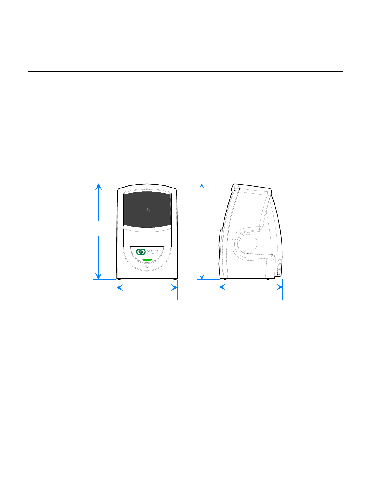
Physical Considerations
The 7893 is a lightweight unit with design consideration given to handling by store personnel.
Weighing about 14 ounces, it is remarkably easy to pick up when necessary. The 7893 requires
minimal counter space as shown below:
140 mm
(5.5 in.)
89 mm
(3.5 in.)
140 mm
(5.5 in.)
91 mm
(3.6 in.)
27356
Page 20

2-2 Chapter 2: Product Information
Environmental Considerations
The 7893 operates in all standard-working environments. Temperature and humidity ranges
permitted are greater when the 7893 is in storage or transit. The following table gives the
various environmental requirements.
Temperature Temperature Change Humidity Range
Operating Environment
(Working Range)
Extreme Power-on Range
Storage Range
Transit Range
Operating
Transit
10°C to 40°C
(50°F to104°F)
-15°C to 45°C
(5°F to 113°F)
-15°C to 50°C
(5°F to 120°F)
-40°C to 60°C
(-40°F to 140°F)
Barometric Pressure Equivalent Altitude (Reference Only)
(105 - 79.5) × 103 Pascal (Pa)
(105 - 74) × 103 Pascal (Pa)
10°C (18°F) / Hour
20°C (36°F) / Hour
20°C (36°F) / Hour
20°C (36°F) / Hour
Up to 2,000 meters (6560 feet)
Up to 2,500 meters (8200 feet)
5% - 95%
(No Condensation)
5% - 95%
(No Condensation)
5% - 95%
(No Condensation)
5% - 95%
(No Condensation)
Power Considerations
An external power supply provides power to the scanner through the interface cable. Due to
power limitations, the 7893 will not be capable of operating solely from 5VDC USB power.
The scanner shall operate with a 12 VDC supply with a peak current draw of less than 1 A.
The power supply input can be 90-264 VAC at 50-60 Hz. A universal power supply comes
with the scanner, depending on the requirements you specify.
Page 21

Chapter 2: Product Information 2-3
Features and Options
The 7893 is rich in features and options. This section details the features and options that are
available.
Scanning Performance
The NCR 7893 uses laser light to create a pattern of 20 scan lines. As a bar code passes
through these scan lines, the 7893 scanner uses the reflected light to identify the location of
each bar in the bar code.
The following illustration displays the scan pattern. Item scanning maybe done from left to
right or vice versa.
The image below shows the 7893 scan pattern.
Communications Protocol
The 7893 communicates with the host terminal through the following:
RS-232
USB (IBM, NCR)
PS/2 Keyboard Wedge
USB Keyboard Wedge
IBM RS–485
27483
Page 22

2-4 Chapter 2: Product Information
Autodiscrimination
The 7893 can decode a variety of barcodes. The ability to differentiate the various barcode
types is a standard feature of the 7893. The following is a list of the different barcode types:
UPC–A and UPC–E
UPC–A and UPC–E with two-digit Add-on Symbols
UPC–A and UPC–E with five-digit Add-on Symbols
GS1–128 Coupon Extended Code
Code 128 Markdown Code
EAN–8 and EAN–13
EAN–13 with two-digit Add-on Symbols
EAN–13 with five-digit Add-on Symbols
GS1 DataBar, formerly Reduced Space Symbology (RSS)
GS1 DataBar–14
GS1 DataBar–14 Stacked Omni–directional
GS1 DataBar Expanded
GS1 DataBar Expanded Stacked
Interleaved 2 of 5
Code 39
Code 39 Full ASCII
Code 128 (including GS1–128)
Multi–Stage Dual for Japan
Codabar
Pharmacode
Page 23

Chapter 2: Product Information 2-5
USB Peripheral Port and Main (POS) Communication Port
The 7893 includes a USB Peripheral ports and a Main (POS) Communication Port. This port is
included to permit an easy connection for peripherals and to improve its capabilities by
permitting the devices to be hot–swappable (connecting or disconnecting devices without
restarting the unit).
The USB peripheral port is located at the underside the unit. The purpose of the single USB
peripheral port is to permit the use of a USB thumb drive.
Note: The total combined 5V current for the USB peripheral port must be limited to 500mA.
USB Peripheral Port
The Main (POS) Communication port is used to connect to the host terminal.
Main (POS) Communication Port
27484
27480
Page 24

2-6 Chapter 2: Product Information
Operator Interface
Interface between the operator and the 7893 is very minimal. Messages are sent from the 7893
to the operator through LED status indicator, audio tones, and voice messages.
Voice Messages
If the 7893 has voice enabled, certain mode changes and error conditions are alerted by
synthesized voice messages. These messages give either the changed mode or the error
message with the suggested corrective action. Voice is enabled and disabled in the
Miscellaneous Parameter program.
Note: By default, Voice is ON.
LED Status Indicator
The LED Status Indicator is an intuitive feature of the 7893. It provides visual confirmation for
scanning items using different colors— which is especially ideal for hearing–impaired cashiers
and enables a quieter front end.
The LED Status Indicator is also useful in diagnosing problems with the 7893. Using a color
coded LED, the user may quickly identify problems – thus effectively decreasing downtime
and enhancing productivity.
LED Status Indicator
27485
Motion Detector
The Motion Detector feature prolongs the life of the 7893. This is located inside the scanner
window; it turns off components of the 7893 after an extended period of non–activity. The
default non–active time is fifteen (15) minutes, but can be changed by programming. An item
passing in front of the Motion Detector causes the 7893 to turn on. This movement is the
normal item scanning movement.
Page 25

Chapter 2: Product Information 2-7
Not–On–File
The 7893 has a Not-On-File feature that locks the scanner and causes the LED Status Indicator
to flash when a bar code is read that is not on file in the store system. This feature prevents the
checker from moving beyond a product not recognized by the system. The Not-On-File feature
is enabled and disabled through programming.
Note: The in-store processor and host terminal must have the host terminal software capable
of supporting Not-On-File determination.
The 7893 is disabled from reading additional tags until the error is cleared. To clear, select the
host terminal’s CLEAR key and manually enter the item and price.
Power Supply
Power Cord (U.S.)
Power Supply
23756
The Power Supply provides the required DC voltage of the NCR 7893 The Power Cord plugs
into an electrical outlet and connects to the Power Supply. A low voltage Power Cable
connects the Power Supply to the 7893. Several power cords are available depending on the
country of installation. The scanner shall operate with a 12 VDC supply with a peak current
draw of less than 1 A. The power supply input can be 90-264 VAC at 50-60 Hz.
In addition, some host terminal interface types can power the 7893 without the use of this
power supply. Please contact your NCR sales representative for details.
Page 26

2-8 Chapter 2: Product Information
Parameter Programming
The NCR 7893 may need to be configured to meet specific installation needs. The 7893 uses
special programming tags to modify the various programming parameters (refer to Chapter 5).
This can be done through the following:
scan using special tags
sent from a PC with the NCR RealPOS Scanner Tool Suite
remotely through the host terminal using the NCR RealPOS Scanner Tool Suite
Note: NCR does not control or specify the NCR scanner configuration required to support
specific host terminal software unless you are using NCR host terminal software. You should
consult with your host terminal software vendor or reseller to determine the correct
configuration for your NCR scanner.
Scan Doctor Diagnostics
Scan Doctor is the state–of–the–art diagnostic software included in every 7893. It continually
monitors the unit to identify components that are not functioning correctly. It also provides
inquiry capability for the host terminal to access specific diagnostic data. Scan Doctor
diagnoses the 7893 each time power is applied and continues all throughout operation. When a
problem is found, it notifies the operator through a color-coded LED on the LED Status
Indicator, and a voice message. It lists the most probable causes first.
Many Scan Doctor statuses are available from the scanner using the NCR Scanner Tool Suite
sold separately.
Power–On Wellness Check
When power is applied to the 7893, Scan Doctor performs a series of diagnostic tests after
Power–On. These diagnostic tests include the following:
RAM (read/write test).
Spinner Motor Speed Test.
Non-volatile Memory Test.
IBM RS-485 TERMPWR Test
Laser Diode Test.
Program Code (ROM sum-check) Test.
FPGA Load Test
If Scan Doctor finds a problem that hinders operation of the 7893 it disables the unit; otherwise
the problem is identified and operation continues.
Page 27

Chapter 2: Product Information 2-9
Ongoing Wellness Check
Scan Doctor runs continuously the moment 7893 is turned on. It constantly performs on-going
diagnostic tests while the unit is running. These diagnostic tests include the following:
Spinner Motor Speed Test.
IBM RS-485 TERMPWR Test
Laser Diode Test.
If a scanner malfunction is discovered during the power-on or on-going diagnostic tests, an
error code will flash on the indicator LED with a unique color sequence. The speech that
accompanies the indicator LED error sequence will suggest corrective action. The following
table lists the supported error codes:
Error Code Problem Suspect Component
0 No power (LED off) Power supply or PCB assembly
2 RAM test failed PCB assembly
5 Motor too slow Motor
6 Bad non-volatile memory (EEPROM) PCB assembly
9 IBM RS485 – no TERMPWR signal IBM host terminal; cable
11 Laser not turned on PCB assembly
12 Program (ROM sum-check) test failed PCB assembly
13 FPGA failed to program PCB assembly
The following table lists the LED color sequences for each error code. The 7893 does not
support all the available color sequences but they are included here for completeness and
future additions:
Error Code Sequence
0 RED ORANGE (PAUSE)
1 RED ORANGE ORANGE (PAUSE)
2 RED ORANGE ORANGE ORANGE (PAUSE)
3 RED ORANGE ORANGE ORANGE ORANGE (PAUSE)
4 RED BLUE (PAUSE)
5 RED BLUE BLUE (PAUSE)
6 RED BLUE BLUE BLUE (PAUSE)
7 RED BLUE BLUE BLUE BLUE (PAUSE)
8 RED GREEN (PAUSE)
9 RED GREEN GREEN (PAUSE)
10 RED GREEN GREEN GREEN (PAUSE)
Page 28

2-10 Chapter 2: Product Information
Error Code Sequence
11 RED GREEN GREEN GREEN GREEN (PAUSE)
12 RED RED (PAUSE)
13 RED RED RED (PAUSE)
14 RED RED RED RED (PAUSE)
15 RED RED RED RED RED (PAUSE)
Note: The 7893 will flash sequences of changing colors that match the Scan Advisor (5-LED
light bar) color sequences used on other PXA scanners like the 7884. Except that the 7893
must flash the colors in sequence instead of displaying them all at once.
Service Diagnostics
Scan Doctor includes service diagnostics for the trained service technician. These go beyond
the wellness checks and are accessed through the use of special programming tags. Refer to
Appendix C for more information on the Scanner Service Diagnostics Tests.
Soft Power Down/Power Up
The 7893 can sense periods of scanner inactivity. The scanner's soft power down feature
extends the life of the 7893 by disabling major portions of the unit, which includes the laser
diode, spinner motor, and associated electronics. The length of the inactive period prior to the
soft power down is user-selected and programmed remotely or through tags.
Scanner power up occurs when the 7893 motion detector detects movement. This detector is
located inside the scan window. The 7893 can also be powered up when the checker signs on
the host terminal. This capability assumes appropriate host terminal software.
Page 29

3
Chapter 3: Installation
Preparing for Installation
There are several things you should do when preparing to install a 7893. Each of these is
discussed in the following sections.
Unpack the Unit
Unpack the unit according to the instructions printed on the box. After everything is out of the
box, take inventory to ensure that you have received all components. The following list
identifies the package contents.
7893 scanner
Power Supply
Scanner Cable
Documentation (also available from the NCR Web site (www.ncr.com
Inspect the Unit for Damage
Inspect the unit for physical damage: broken or scratched scan window, broken or scratched
cabinet, and so forth. If the scanner has been damaged due to shipping, notify the shipping
carrier and the NCR representative. If other damages are found, notify NCR or the other
supplier if not purchased directly from NCR. Out of Box failures are handled through the NCR
customer Satisfaction Hot line.
)
Page 30

3-2 Chapter 3: Installation
Verify Correct Cables
The following table identifies the most common interface cables required for the different host
connections that can be made with the 7893. See your NCR representative for additional
cables.
Cable Number Description
1432-C899-0040 Cable – USB, Latching, 7892SA, black
1432-C679-0040 Cable – PS/2 Keyboard Wedge, SuperASIC, black, coiled
1432-C897-0040 Cable – USB, non-latching
1432-C038-0030 Cable – Powered RS-232, Checkpoint, (coiled), black
1432-C967-0030 Cable – RS-232 Powered-Straight (black), coiled section
1416-C971-0030 Cable – RS-232 Scanner-Coiled (black)
1416-C807-0030 Verifone Ruby Powered Cable
1416-C547-0030 468X-9B
1416-C768-0040 Cable – Scanner, Gilbarco-coiled w/ RJ-45
Identifying Available Kits
A Power Brick for the electrical requirements you specified must be ordered with the 7893 if
host terminal power is not used.
The following table identifies the kit number for all available kits.
Kit Number Kit Description
7892-K125-V003
7892-K111-V003
7892-K129-V002 Kit – US Power Supply with Twist Lock Power Cord
7892-K120-V002 Kit – Universal Input, +12v output Power Supply
7892-K119-V002
7892-K128-V001 Kit – SEV Power Supply and Swiss Cordset
7892-K118-V003
7892-K901-V001 Kit – Stand NCR-CG1
Universal Input, +12v output Power Supply w/ Australian Cable with
Straight 'BM' Power
Kit – Universal Input, +12v output Power Supply, North American &
Japanese
Universal Input, +12v output Power Supply, UK Plug with Straight
'BM' Power, RoHS
(7892-K119-V002)
Universal Input, +12v output Power Supply, European w/ Cord-Power
(Intl)
Page 31

Chapter 3: Installation 3-3
Determine Scanner Location
When identifying a location for the 7893 scanner, consider the length of the connecting cables.
The electrical outlet used for the Power Module can be approximately 74 in. (188 cm) from the
host terminal. Depending on the Scanner Module Cable, the scanner can be approximately 9 ft.
(274 cm), 6.6 feet (2 meters) or 13.1 feet (4 meters) from the host terminal or PC. These
distances are normally shorter depending on how you route the connecting cables. Be sure that
the Scanner Module Cable is long enough to permit the scanner to be picked up when required
for large packages.
Like any electronic device, the 7893 should not be located in direct sunlight. Temperatures
above 104 degrees Fahrenheit (40 degrees Celsius) can occur when sunlight falls on objects
through windows or on an outdoor checkstand.
Page 32

3-4 Chapter 3: Installation
Installing the 7893
The 7893 can be connected to the host terminal through a PS/2 keyboard connector. Scan data
is input into the PS/2 keyboard port. When connected in this configuration the 7893 cannot
receive commands from the host terminal.
Note: For the 7893 there is only a single transmit message buffer. Also, the transmission of
the data can be significantly longer than other communication protocols; the time depends on
the length of the intercharacter delay.
Note: The PS/2 Keyboard Wedge cable connects both the scanner and the keyboard to the
host terminal through the PS/2 keyboard port. This cable has two PS/2 connectors. If the host
terminal system has an AT keyboard connector, two adapters are required: an AT to PS/2 and a
PS/2 to AT. These adapters are available locally at most computer stores. For more
information about PS/2 Keyboard Wedge, see Appendix A.
Belkin F2N017—AT to PS/2
Belkin F2N018—PS/2 to AT
Keyboard Wedge Cable
1416-C636-0030
Keyboard
Scanner Cable
Host Terminal
Power Cable
AC Power Cord
7893 Scanner
Power
Supply
27473
Page 33

Chapter 3: Installation 3-5
USB Keyboard Wedge Communication
The 7893 can emulate a USB keyboard device by enumerating itself as an HID keyboard. By
doing so, it passes barcodes directly to the host’s keyboard driver. This eliminates the need of
installing a third party driver since the operating system’s native keyboard input driver will be
used.
Programmables
1. Enable USB keyboard Communications Interface
Programming Mode + 1 + 0 + E + 3
2. Inter Character Delay
4 ms: Programming Mode + 2 + 8 + D + 0
8 ms: Programming Mode + 2 + 8 + D + 1
16 ms: Programming Mode + 2 + 8 + D + 2
32 ms: Programming Mode + 2 + 8 + D + 3
64 ms: Programming Mode + 2 + 8 + D + 4
1 ms: Programming Mode + 2 + 8 + D + 5 (New for this release, new default value)
3. Start and Stop Sentinel, maximum of 9 bytes each
Disable: Programming Mode + 2 + 9 + 0 (zeros all start/stop entries)
Start Sentinel: Programming Mode + 2 + 9 + 1 + DATA + End
Stop Sentinel: Programming Mode + 2 + 9 + 2 + DATA + End
DATA Input: Enter each byte as 2 nibbles
Example: Start Sentinel = 0x31, 0x21, 0x2D (0x31 will be transmitted first)
DATA Tag Sequence = 3 + 1 + 2 + 1 + 2 + D
Tag Message Format
The Tag Message will consist of the following:
Start Sentinel – 0 to 9 bytes
Tag Identifier – 1 byte
Tag Data – Variable, depending on the scanned tag
Stop Sentinel – 0 to 9 bytes
Page 34

3-6 Chapter 3: Installation
Connecting Power
1. Verify that you have the correct Power Module for your electrical outlet.
2. Connect the power connector to the Interface Cable. Depending on the installation, this
may be a connector on the cable or a box on the end of the cable.
3. Plug the Power Module into an electrical outlet. When the 7893 receives power, the
diagnostics checks various hardware components. If the scanner passes the diagnostic
tests, it gives a "ready" indication (four flashes of the LED Status Indicator). A green flash
followed by a red flash is normal and indicates the scanner serial number is stored in the
scanner’s EEPROM.
Note: If the 7893 is receiving power from the host terminal, do not connect the Power
Module.
Host Terminal
Interface Box
Dongle Adapter Cable
7893 Scanner
Scanner Cable
27474
Warning: When the host terminal powers the 7893, do not plug the unit in live. This can
cause the Power Supply in the host terminal to shut down and may also blow an internal
fuse in the host terminal. Be sure to turn off the power to the host terminal before
connecting the 7893.
Page 35

Chapter 3: Installation 3-7
Modifying the Scanner Program
The 7893 comes from the factory with all programming parameters set to default values. For
changes on any values that do not match the system requirements, refer to Chapter 5,
Programming.
Communications Protocol
The Communications Protocol programming mode selects the protocol that the 7893 uses to
communicate with the host terminal.
Note: The factory sets the Communications Protocol according to the specifications on your
order. Since there is no default Communications Protocol; the Default tag does not change this
parameter.
IBM RS-485
The 7893 supports the IBM 468x/9x format and use the same protocol found on IBM host
terminals.
RS-232
RS-232 is used to connect the 7893 to almost any RS-232 type of communications device. This
protocol uses 7-bit ASCII to send tag to the device.
IBM USB
The 7893 can communicate to the host terminal through a USB cable. This parameter enables
the IBM-USB format.
NCR (RS-232) USB
The 7893 can communicate with the host terminal through a USB cable. This parameter
enables the NCR (RS-232) format.
Note: Two programming tags must be scanned to enable this parameter: Hex E followed by
Hex 0.
Wedge
The 7893 can communicate to the host terminal through a Wedge cable.
Page 36

Page 37

4
Chapter 4: Operating the Scanner
Scanner Components
Before using the 7893, the user needs to be familiar with some of its components. The figure
below shows the scanner and identifies some of the parts and features.
Scan Window
Scanner Module Cable
Status Indicator
Speaker
27475
Page 38

4-2 Chapter 4: Operating the Scanner
Pass-by Scanning
This type of scanning is the familiar style used at checkout stands, such as in supermarkets.
The item is moved across the front of the scanner window with the barcode label oriented to
face the scanner window, as shown.
When the label is read the LED Status Indicator turns GREEN. If enabled, a Good Read Tone
also sounds.
Scan Window
27476
Presentation Scanning
Presentation scanning is much different from that used at checkout stands, such as in grocery
stores. In the checkout stand environment, normally large quantities of items must be scanned
in a short amount of time. Therefore, you pass the items over the scanner, moving them from
one side of the checkstand to another. The scanner reads the label while the items are moving
by.
With presentation scanning, you simply present the label to the scanner and then remove it. Do
not move the label past the scanner, but to the scanner. Presentation scanning is particularly
useful in a retail environment where the number of items associated with each transaction is
normally small. There are three simple steps to presentation scanning.
1. Move the bar code label to the scanner as shown.
Scan Window
27477
Page 39

Chapter 4: Operating the Scanner 4-3
2. Position the bar code label completely within the red Laser Scan Pattern as indicated
below. Normally the bar code should be three to four inches from the scanner. When the
label is read the LED Status Indicator turns green. If enabled, a Good Read Tone also
sounds.
Laser Scan
Pattern
27478
3. Move the bar code label away from the scanner as shown. The scanner is now ready to
read another bar code label. To read another bar code, simply perform these three steps
again.
27479
Page 40

4-4 Chapter 4: Operating the Scanner
Hand Scanning
Occasionally you have merchandise that cannot be picked-up and presented to the scanner. The
package may be too heavy or too awkward to hold while trying to position the bar code label.
In these circumstances you can pick up the scanner and take it to the merchandise. The 7893 is
designed so that you can easily pick the scanner up and hold it. Being light-weight, you can
present the scanner to the merchandise with little effort.
Careful
Label Orientation
Because the 7893 produces a dense, omni-directional scan pattern, labels can be read from
many different angles.
Scan Pattern Location
In order for the scanner to read a label, the center 90% of one scan line must cross the bar
code. To successfully read Code 39 and Interleaved 2 of 5 labels, the scan line must cross the
entire label, not missing any of the bars or spaces. UPC and Code 128 labels can be read by
piecing together two reads of slightly more than half of each side of the bar code. Therefore,
these labels are much easier to read and do not require as much accuracy when presenting the
label to the scanner.
17269
Because of the large scan pattern, you do not have to be very precise when you position the
label. However, the concentration of scan lines is greater in the center of the scan pattern.
Because of this, fewer rejects occur if you try to position the merchandise so that the label is
presented toward the center of the scan pattern.
Page 41

Chapter 4: Operating the Scanner 4-5
Label Rotation
The 7893 can read labels that are presented in many different positions. You can present labels
that are rotated left or right 30 degrees from center, up or down 30 degrees from center, and
360 degrees around center.
30
30
30
360
30
27481
Page 42

4-6 Chapter 4: Operating the Scanner
Distance from Scanner
For optimum reading, the distance you must place the label from the 7893 depends on the
density and height of the bar code. You can relate this to focusing a camera, where you change
the focus setting based on how far away the object is.
Depending on the label, reading can range from zero to six inches. Therefore, when you use
your scanner, move the label toward the scanner to a comfortable distance in front of the scan
window (approximately three to four inches) and hold the item momentarily. Normally the
"Good Read" indication occurs within one fourth of a second. If this does not happen, try
moving the label a little closer to the scanner.
Bar Code Quality
The ability of your 7893 to read bar code labels depends greatly on the quality of the label.
Although the 7893 can often read bar codes that appear to be bad, it cannot read bar codes that
are obstructed, defective, or damaged. If the scanner cannot read the bar code, you must key in
the merchandise information at the host terminal and go on to the next item. Be sure to tell
your supervisor if many bar code labels are defective. The figure below shows some examples
of bad bar codes. These are only examples and are not all-inclusive.
06
06
06
01 23 4 67 85 9
Bar Code Scratched Bar Code Folded Bar Code Truncated
06
0 1 23 4 67 85 9
Bar Code Torn Poor Color Contrast Red Bar Code On
0 1 23 4 67 85 9
06
01 23 4 67 85 9
01234 67859
0 1 234 67 85 9
06
Red Background
R0026
The readability of a label depends on variables such as sizing, placement, color, paper type, ink
viscosity, and package coatings. The middle of a printing run can yield erroneous labels due to
the many variants involved. In particular, poor color contrast and marginal print quality can
make a label hard to read.
A label should be considered readable if it meets or exceeds the requirements set forth in the
EAN UCC General Specification 1/2000.
Page 43

Chapter 4: Operating the Scanner 4-7
PACESETTER
NCR has continually improved its PACESETTER technology used on NCR scanner products.
Starting out as PACESETTER, it progressed to PACESETTER Plus, and then to
PACESETTER III. Vendors and printers regularly supply products with overprinted,
underprinted, or truncated bar codes to the market. Some labels have missing margins. Others
may be printed around the corner of packages or on media that wrinkles when picked up.
PACESETTER addresses the problems caused by these unreadable labels. PACESETTER III
is standard on all NCR scanner products.
PACESETTER Plus
PACESETTER Plus determines what is wrong with a bar code label, fixes the data, and then
transfers the information to the host terminal. It provides information on possible bar code
printer problems but is not a bar code specification conformity verifier.
The three modes of PACESETTER Plus operation are summarized in the following
paragraphs.
Mode 1–Inquiry
PACESETTER Plus can be used as a management tool by store personnel and chain
management to monitor and report the status of label readability. Tally counters are kept for
the following.
Good reads
No read due to lack of full label (missing bars or folded label)
Good reads with overprinted bars
Good reads with underprinted bars
Missing margins
Missing print lines
Mode 2–Demonstration Mode
In Mode 2, the scanner is offline. Each subsequent scan of a bar code causes the scanner to
indicate the status of label readability. The scanner recognizes missing bars in labels, highly
overprinted or underprinted labels, missing margins, or a “no read” condition.
Mode 3–Operations
Mode 3 is the normal operating mode. The scanner can be programmed to add PACESETTER
Plus information to the decoded UPC/EAN data. This information describes the label
readability. However, the host terminal software must be capable of receiving the extra data.
The host terminal software should enable this at a regular interval (for example, Cashier Sign
On) and check for the presence of the data if enabled.
Page 44

4-8 Chapter 4: Operating the Scanner
PACESETTER III
The PACESETTER III feature of the 7893 scanner performs many functions that improve the
efficiency of the scanner. It determines what is wrong with a bar code and then fixes it. It also
keeps track of problems found.
PACESETTER III also detects, corrects, and reports errors discovered in UPC Number System
Two and Number System Four labels. These two label types are printed in the store and
account for a significant number of unreadable labels due to failures of the in–store printing
mechanism. PACESETTER III looks for errors in these labels and learns from each attempted
scan. After seeing a particular printing error a number of times, PACESETTER III may
determine that an error is present in the label and that the error may be correctable. If the
correction capability of PACESETTER III is enabled, the scanner attempts an error–free
correction of the label and passes the results to the host terminal. Whenever an error–free
correction is not possible, PACESETTER III does not pass label data to the host terminal.
Read Indicators
The 7893 provides two methods of indicating valid reads: LED Status Indicator (visual) and
Audible Tone (audio). The LED Status Indicator is always enabled; however, you can disable
the Audible Tone.
LED Status Indicator
The LED Status Indicator light is located above the speaker. When the 7893 detects bar code
data, the laser turns on and the LED Status Indicator turns GREEN. When an accurate read of a
valid bar code occurs, the LED Status Indicator turns from GREEN to GREEN until the bar
code is removed; it then turns GREEN again.
When using IBM 468x communications, the LED Status Indicator flashes PINK (group of nine
flashes repeated at 3-second intervals) when the 7893 is offline. This can be caused if the IBM
host terminal has not established communications with the 7893, the host terminal is not turned
on, or the interface cable is not connected.
Audible Indicator
You can program a "Good Read" tone that indicates the scanner's ability to accurately read bar
codes. This permits you to identify good reads without having to observe the LED Status
Indicator. No tone is generated if the scanner does not detect a valid bar code.
You can enable or disable the Good Read Tone. If the Good Read Tone is enabled, you can
also specify its volume and duration. Details for programming the Good Read Tone are in
Chapter 5, Programming. The 7893 scanner comes with the Good Read Tone enabled.
Speech Functionality
The 7893 has the ability for speech. If speech is enabled the unit will speak during
programming, during diagnostics, and when the unit encounters an error.
Page 45

Chapter 4: Operating the Scanner 4-9
Programming Speech
Speech on the 7893 is enabled or disabled by scanning the following programming sequence.
Speech Enable/Disable toggle
Programming Mode
Hex 3
Hex 2
Hex D
Save and Reset
Scan the programming tag sequence once to enable speech. Scan it a second time to disable
speech.
Speech in Foreign Languages
The language used in the speech function of the 7893 can be toggled between English and
foreign languages (French and Spanish). Scan the following programming tag sequence to
change the language of speech.
Note: The default language for speech is English.
Setting Speech to a Foreign Language
Programming Mode
Hex 5
Hex 6
Hex 1
Save and Reset
Setting Speech to English (Default)
Programming Mode
Hex 5
Hex 6
Hex 0
Save and Reset
Page 46

4-10 Chapter 4: Operating the Scanner
Taking Care of Your Scanner
Although your 7893 is rugged, remember to treat it carefully. Keeping the Scan Window clean
helps keep the read rate exceptionally high. Follow these simple instructions to keep your
scanner clean and well-maintained.
Clean the scanner body with a soft cloth dampened by lukewarm water and a mild soap.
When the Scan Window is dirty, clean it with a cloth dampened with lukewarm water.
The 7893 is designed to provide you with long, trouble-free service. However, it is up to you to
care for your scanner. The following list identifies things to consider in taking care of the
scanner.
Handle the scanner with care.
Keep the Scan Window clean.
Do not pick up the scanner by the cable.
Do not submerge the scanner in any liquid or let it get wet.
Page 47

5
Chapter 5: Programming
This overview of programming the 7893 is intended to acquaint you with the overall
programming procedure. The “Scanner Programming Summary” section at the end of this
chapter is most useful after you have performed the programming function.
Programming Mode
To program the 7893, it must be in the Programming Mode. Enter this mode by scanning the
Programming Mode tag immediately after applying power to the scanner; it must be the first
tag scanned. This puts the scanner in the Base Programming state. When entering the Base
Programming state, the scanner produces a long then short beep; the LED Status Indicator
stays off. If speech is enabled, the scanner says “Program Mode”.
From the Base Programming state, select specific programming modes by scanning the proper
two hexadecimal tags. The program parameters that you enter in a specific programming mode
are identified on the associated Programming Worksheet.
In each specific programming mode, enter all the information contained on the worksheet by
scanning all the proper tags in sequence as shown on the worksheet. In addition, use parameter
shortcuts to enter a specific parameter. Program entry goes directly to a specific parameter
when you scan the proper Hex tag.
If you do not know how your 7893 is programmed, you can set it to all defaults then enter any
required changes to match your program. Do this by scanning the Default tag as the first tag
after applying power to the scanner. This sets the defaults for the programmed default setting
in the scanner. Next, scan the Programming Mode tag to enter the Programming Mode.
The scanner accepts programming tags only in the Programming Mode. If you scan a
programming tag during normal operation, nothing happens.
Preparing for Your Program
Determine the requirements for your program, such as communications protocol, use of good
read tone, timeouts, bar code types, label identifiers, RS-232 requirements (if using this
protocol) and defaults. You may need to read your system application documentation.
Completing the Worksheets
Programming parameters are contained in the Programming Worksheets. Before using the
worksheets, read the “Using the Programming Worksheets” section at the beginning of
Chapter 7.
Page 48

5-2 Chapter 5: Programming
You need to know the communication protocol that your host terminal is using so that you can
program your 7893 to the same protocol. If you are unsure of the setting in your scanner, scan
the Default tag. The unit should make one long beep followed by the number of beeps
corresponding to the communication protocol. (See Chapter 3 in this manual.) If this is not the
desired default, program the communication protocol first, and then program any additional
parameters using the programming tags and worksheets.
The Programming Worksheets identify the default values that are determined at the factory.
You only need to use the worksheets that need changing for your particular requirements.
Enter your program at the bottom of each worksheet. Be sure to read the sections later in this
chapter that relate to the worksheets you are using.
Entering Your Program
Enter your program by performing three basic steps:
1. Enter the Base Programming state by scanning the Programming Mode tag first
after applying power to the 7893 scanner.
2. Select a Programming Worksheet and enter its parameter data by scanning the
Hex tags identified in Your Program at the bottom of the Programming Worksheet.
Repeat this for each worksheet used if the default is changed.
Requirements
Help
Suggestion
3. Save your program by scanning the Save and Reset tag.
Programming Worksheets
Programming Tags—Appendix B: NCR Scanner Programming Tags or BST0-2121-74
Refer to the “Programming Tags Chart” later in this chapter.
Refer to the step-by-step procedure described in “Entering Your Program” section of this
chapter.
Refer to the “Scanner Programming Summary” later in this chapter.
Refer to “Using the Programming Worksheets” later in this chapter.
If you do not know how your scanner is programmed then you can scan the following
sequence to set it to Factory Defaults then make the necessary changes.
PROGRAM MODE
HEX 3
HEX 4
HEX 0
SAVE&RESET
Page 49

Chapter 5: Programming 5-3
Note: The Factory Default for the 7893 is RS-232, 9600 baud, 7-bit data, and 1-stop bit.
Programming Considerations
The 7893 is fully programmable to meet your system requirements.
When you receive your 7893, it is already programmed with default values set at the factory.
However, if you need to make programming changes, the procedure is very simple. First
complete a series of programming worksheets then enter the information using special
Programming Tags in Appendix A: NCR Scanner Programming Tags or BST0-2121-74.
Programming Tags
There are 5 unique tags and 16 hexadecimal (Hex) character tags. The following chart
identifies each Programming Tag, its function, and the associated indicators.
Tag Function Indication
Default
This tag causes most parameters to go to
default values. However, scanning this
tag does not change a few parameters,
including the Communications Protocol.
The Default tag must be the first tag
scanned after applying power to the
7893.
Performs power-up sequence.
Programming
Mode
End
This tag puts the 7893 in the Base
Programming State. It must be the first
tag scanned after applying power to the
7893, or after scanning the Default tag.
This tag ends certain input sequences.
Since the programming mode
determines the end of most sequences,
this tag is not used often.
LED Status Indicator—off.
Short beep as soon as tag is read—
Good Read tone.
Long and short beep—In Base
Programming State.
If Voice is enabled, “Program
Mode” is spoken and no beep
sounds.
LED Status Indicator flashes green
once.
Short beep as soon as tag is read—
Good Read tone.
If Voice is enabled, a short beep
sounds and returns to “Program
Mode”.
Page 50

5-4 Chapter 5: Programming
Tag Function Indication
Save and Reset
This tag causes the 7893 to save and
start using the programming data. It is
used in the Base Programming State.
LED Status Indicator flashes red
twice.
Short beep as soon as tag is read—
Good Read tone.
If Voice is enabled, a short beep
sounds and resets the scanner.
Abort
Hex 0-Hex F
If this tag is scanned in the Base
Programming State, programming is
terminated and no previously entered
parameters are saved.
These 16 tags enter the selections for
each of the parameters in the Parameter
Programming Modes. They also select
the Parameter Programming Mode.
LED Status Indicator flashes green
once and returns to dim green.
Short beep as soon as tag is read—
Good Read tone.
If Voice is enabled, a short beep
sounds and returns to “Program
Mode”.
Hex 0—no beep
Hex 1 through Hex F—Beeps tag
value. Multiples of 4 short beeps
grouped together. Others are
longer
Example: Hex D is indicated by
12 short beeps (3 sets of 4)
followed by 1 longer beep, for a
total of 13.
Note: In programming tag
sequence, no beep for the second
Hex tag; one short beep (different
frequency from the Good Read
Tone) after the last Hex tag.
Using the Programming Worksheets
The Programming Worksheets provide a convenient method of defining your 7893 program
before loading it into the scanner. Each worksheet relates to a specific programming mode.
Enter your selections and changes on the Worksheets. Save this information for future use
should it be necessary to re-enter this program.
Most of the programming options have defaults that are determined at the factory. A bolded
box around an entry selection specifies it as the default value. Scanning the Default tag as the
first tag after applying power to the 7893 sets the parameters to these values. The scanner also
indicates via beeps the Default setting.
Enter the program into your scanner by scanning the proper sequence of programming tags
found in the NCR Scanner Programming Tags (BST0-2121-74). Following are the three major
steps to programming your scanner.
If Voice is enabled, “0” through
“F” is spoken and no beep sounds.
Page 51

Chapter 5: Programming 5-5
1. Enter the Base Programming state by scanning the Programming Mode tag as the first tag
after applying power to your 7893 scanner.
2. Select a Programming Worksheet and enter its parameter data by scanning the Hex tags
identified in Your Program at the bottom of the Programming Worksheet. Repeat this for
each worksheet.
3. Save your program by scanning the Save and Reset Tag.
Caution: Some host terminals can corrupt your program if they are running and are
connected to the 7893 while you are entering a program. Either turn off the host terminal or
disconnect the interface cable from the host terminal before entering your program.
Note: In most instances the factory determined defaults are the correct parameter settings.
Normally you only need to change a few of these parameters and do not need to enter all the
Programming Worksheets. When programming your scanner, it is recommended that you first
set all the parameters to default values by scanning the Default tag, then make any necessary
changes to the appropriate parameters. If you need to change the Default protocol, program
that first.
Page 52

5-6 Chapter 5: Programming
Programming Description
The 7893 can be remotely programmed from its attached host terminal with no local
intervention. To achieve this, special host terminal software (NCR RealPOS Scanner Tool
Suite) must be purchased from NCR. This section describes programming a scanner with
special bar code tags.
Programming the 7893 consists of setting programming parameters to match specific needs.
This is accomplished by scanning a specific sequence of programming tags. The factory sets
most programming parameters to default values or values originally specified. In most
installations, few, if any, programming changes need to be made.
Creating the Program
Creating a program consists of three basic steps. Details of these steps are given in various
areas of this programming information.
Write the Program
1. Identify requirements. The first thing is to determine the requirements of the 7893
installation. This includes information about the communications protocol, the types of bar
codes to be scanned, the use of good read tones, and scanner time–outs.
Note: NCR does not control or specify the NCR scanner configuration required to
support specific Host Terminal Software unless you are using NCR Host Terminal
Software. You should consult with your Host Terminal Software vendor or reseller to
determine the correct configuration for your NCR scanner.
2. Complete the programming worksheets. Using the descriptions contained in this document,
complete each programming worksheet. Write the entries of the program in the space
provided. Refer to the “Programming Worksheet” section in Chapter 5 for specific
information about each parameter.
Enter the Program
1. Enter the programming mode. Scan the Program Mode tag. This must be the first tag
scanned after supplying power to the
7893 (or the first tag after scanning the Reset tag).
2. Enter the parameters for each specific program. Scan the two Hex tags to select a specific
program, and then enter all parameter data for it. After all the information has been
entered, the 7893 returns to programming mode. Repeat this procedure for each specific
program that needs to be changed.
Note: A specific program does not need to be entered if its associated programming is
already correct.
Save the Program
1. Scan the Save and Reset tag. When the Save and Reset tag is scanned, the scanner saves
all programming parameters entered. This becomes the new scanner program. The scanner
goes through initial startup and operates using the new program.
Page 53

Chapter 5: Programming 5-7
2. Save programming worksheets. Be sure to save the programming worksheets that contain
the scanner program. It is much easier to reenter the program, or change some of it, if a
written record of the program exists.
Normal Operating Mode
Normal Operating Mode
Programming Mode Tag
Programming Mode
Parameter Program
Parameter Program
Programming Tags
After completing the worksheets, enter the information using the special programming tags
contained in the NCR Scanner Programming Tags (BST0-2121-74) available at
www.info.ncr.com
number of special programming tags are not needed. There are only five (5) unique tags and
sixteen (16) hexadecimal (Hex) character tags. The following identifies each programming tag,
its function, and the associated indicators.
ABORT
Function–In Base Program Mode
If the Abort tag is scanned in the Base Program Mode, programming is terminated and
previously entered parameters are not saved.
Indication–In Program Mode
LED Status indicator dim green and then flashes bright green showing the tag was read.
Scanner will reboot and perform power up sequence (the LED Status Indicator turns off
momentarily, then comes on with a blue LED followed by a gradual change to bright
green, then back to normal state at dim green).
Save and Reset Tag
16402
. (The tags are also included in Appendix A of this document.) A large
Short beep as soon as tag is read—Good Read tone
Motor stop momentarily while scanner reboots, then they come up to full speed
Page 54

5-8 Chapter 5: Programming
Function–In a Parameter Programming
If this tag is scanned in a Parameter Program sequence, only the parameter sequence which
was aborted is not saved. Any prior sequence that successfully ended with the scanner saying
"Program Mode" is saved and the 7893 stays in Program Mode.
Indication–In a Parameter Program
LED Status indicator flashes green once and then returns to dim green
Short beep as soon as tag is read—Good Read tone
Programming returns to Program Mode
Scanner beeps to indicate it accepted the Abort tag, and then says "Program Mode"
DEFAULT
Function
This tag causes most parameters to reset to default values. However, scanning this tag does not
change a few parameters, including the Communications Protocol. The Default tag must be
scanned first after applying power to the 7893
Note: The Default tag is not used while in Programming Mode
Indication
Speaks “Set new default parameter complete”, LED Status Indicator flashes bright green
after speaking then beeps once.
Performs power-up sequence (the LED Status Indicator turns off momentarily, then comes
on with bright blue LED followed by a gradual change to bright green, then back to normal
state at dim green).
END
Function
This tag ends certain input sequences. Since the parameter program determines the end of most
sequences, this tag is not used often.
Indication
LED Status indicator is initially dim green and then flashes bright green showing the tag
was read.
Short beep as soon as tag is read—Good Read tone.
Scanner beeps to indicate it read the End tag, then it says “Program Mode” as it goes into
Program Mode.
Page 55

Chapter 5: Programming 5-9
HEX 0–HEX F
Function
These sixteen (16) tags enter the selections for each of the parameters in the Parameter
Programs. They also select the Parameter Program
Indication
Hex 0—Scanner says “Zero” with no beeps. If voice disabled, scanner produces a short
beep, different frequency from Good Read tone.
Hex 1 through Hex F—Scanner says “<tag value>” with no beeps. If voice is disabled,
the scanner produces a number of beeps according to the tag value. Multiples of 4 short
beeps grouped together.
Example: Hex D Scanner says “D”. If voice is disabled, Hex D is indicated by 12 short
beeps (3 sets of 4) followed by 1 beep, for a total of 13.
PROGRAM MODE
Function
This tag sets the 7893 into Program Mode. It must be the first tag scanned after applying power
to the 7893, or after scanning the Default tag or the Reset tag.
Indication
LED Status indicator is initially dim green and then flashes bright green showing the tag
was read.
The scanner says “Program Mode” with no beeps.
If Voice NOT enabled, Short beep, long beep, short beep—indicates Program Mode
SAVE AND RESET
Function
This tag instructs the 7893 to save and start using the programming data. It is used in the
Program Mode.
Indication
LED Status Indicator flashes red twice, then scanner reboots and performs power up
sequence (the LED Status Indicator turns off momentarily, then comes on with bright blue
LED followed by a gradual change to bright green, then back to normal state at dim green).
Short beep as soon as tag is read—Good Read tone
Motor stops momentarily while scanner reboots, then they come up to full speed.
One beep when the scanner has completed power cycling.
Reboots with no voice.
Page 56

5-10 Chapter 5: Programming
Speak Bar Codes Currently Enabled
This bar code prompts the scanner to speak a list of the bar code symbologies that the scanner
has been programmed to recognize and read. Refer to Appendix B for the actual programming
tag.
Indication
The LED Status Indicator stays dim green.
Scanner begins speaking as soon as bar code is scanned. It talks and lists all the bar codes
Scanner beeps when it is done speaking the enabled symbologies.
Speak Scanner Serial Number
This bar code enables the user to obtain the scanner Serial Number without having to remove
the scanner from the checkstand (if installed) and looking at the manufacturing name plate
label on the back of the unit. Refer to Appendix B for the actual programming tag.
currently enabled in the scanner.
Example: “UPC EAN is ON, Periodical P2 is ON...Periodical P5 is ON...Code 128 is
ON.”
Indication
The LED Status Indicator light up bright green while it is speaking then goes back to dim
green when it is done.
As soon as the scanner reads the bar code, it says “Scanner S N” then speaks all 10 digits.
If the scanner says “Scanner S N 0 0 0 0 0 0 0 0 0 0”, then the actual serial number is NOT
stored in memory.
The scanner beeps when it is done speaking the serial number.
Program Entry Procedure
Enter All Parameters
To enter all parameters in a Parameter Program, scan the two Hex codes that set the 7893 in
the Parameter Program, and then make parameter changes in the order described on the
programming worksheet for that mode. When programming all parameters in a specific mode,
proceed directly through the work sheet. When making a change in a parameter, the scanner
proceeds to the next parameter to be changed or it goes back to Program Mode if the selection
ends programming in that particular Parameter Program.
The following figure shows how to proceed through a Specific Programming Mode where all
parameters are entered. It presents the Parameter Program for the Bar Codes 2 program
parameters. The figure shows how to proceed through the Parameter Program by entering all
available parameters. Notice that (in this example) if Code 39 bar codes are disabled,
programming immediately returns to Program Mode. However, if Code 39 bar codes are
enabled, the scanner directs the user to continue entering parameter information.
Page 57

Chapter 5: Programming 5-11
PROGRAM MODE
1
4
Bar Codes - 2
Parameter Program
Code 39
Minimum
Disable Enable
2-F
10
Characters
Allowed
Full ASCII
Check Digit
Present
Transmit
Check Digit
01
Disable Enable
10
Disable Enable
01
Disable Enable
Allow 1- or
2-Character
Tags
01
Disable Enable
11722
Page 58

5-12 Chapter 5: Programming
Program Entry Procedure
The following example is a typical program entry procedure.
1. Disconnect scanner from the host terminal.
2. Apply power to the 7893 (or scan the Reset tag).
3. Scan the Program Mode tag.
4. Scan the two Hex tags corresponding to the worksheet number.
5. Scan appropriate Hex tags to enter parameters.
6. Repeat steps 4 and 5 until all the parameters are entered.
7. Scan the Save and Reset tag. All parameter changes are saved and 7893 is reset (goes
Enter Specific Parameters (Shortcut Method)
To enter only one specific parameter in a Parameter Program, scan the two numbered Hex tags
that correspond to that Parameter Program. However, once the Parameter Program has been
entered instead of immediately changing parameters with numbered Hex tags, use the lettered
Hex tags to choose the one particular parameter to be changed. After the new parameter setting
has been selected, the scanner immediately returns to Program Mode. If one decides to do
additional programming with these parameter options, reenter the Parameter Program by
scanning the two Hex tags again.
through initial power-up sequence). The 7893 now operates using the new program.
The following figure shows how to proceed through a Parameter Program where shortcuts are
used to change only one of the parameters. This figure presents the Parameter Program for Bar
Codes 2 program parameters. Notice that once the Parameter Program has been entered, if the
Hex A, Hex B, Hex C, Hex D, Hex E, or Hex F tag is scanned, the specific parameters that
correspond to that tag can be entered. After recording the parameters, the scanner immediately
returns to Program Mode. To return to programming, scan the
Hex 1 and Hex 4 tags again and reenter the Parameter Program. From this point, enter either
all parameters or another specific parameter.
Page 59

Chapter 5: Programming 5-13
PROGRAM MODE
1
4
Bar Codes - 2
Parameter Program
2- F
10
A
B
Code 39
Disable Enable
Minimum
Characters
Allowed
C
D
E
Full ASCII
Check Digit
Present
Transmit
Check Digit
01
Disable Enable
10
Disable Enable
01
Disable Enable
F
Allow 1- or
2-Character
Tags
01
Disable Enable
11723
Page 60

5-14 Chapter 5: Programming
Program Entry Procedure (Shortcut Method)
The following example is a typical program entry procedure.
1. Disconnect scanner from the host terminal.
2. Apply power to the 7893 (or scan the Reset tag).
3. Scan the Program Mode tag.
4. Scan the two Hex tags corresponding to the worksheet number.
5. Scan specific parameter tag (Hex A–F).
6. Scan appropriate Hex tags to enter parameters.
7. Repeat steps 4 thru 6 until all the parameters are entered.
8. Scan the Save and Reset tag. All parameter changes are saved and 7893 is reset (goes
through initial power–up sequence). The 7893 now operates using the new program.
Parameter Defaults
Programming Mode Program Parameters Default Setting
Communications
Protocol
Protocol
No default value—
remains as
programmed
Good Read Tone
Timers
Tone On/Off On
Tone Frequency 2232 Hertz
Tone Length 45 ms
Tone Volume 2
Not–On–File Volume 0
Lockout Time 450 Milliseconds
Restart Lockout Timer On
Active Time 15 Minutes
900ms Lockout Timer Restart Limit Off
Page 61

Chapter 5: Programming 5-15
Programming Mode Program Parameters Default Setting
UPC/EAN Enable
Unused Disable
Extend UPC–A to EAN–13 Disable
Bar Codes-1
Bar Codes-2
Extend UPC–E to UPC–A Disable
Periodical Codes Disable
Periodical Code Extension No default value
Send Data Data As Decoded
Set 2 Tag Label Off
Code 39 Disable
Minimum Characters Allowed 8
Full ASCII Disable
Check Digit Present Disable
Transmit Check Digit Disable
Allow 1- or 2-Character Tags Disable
Code 39 Tone Disable
Tone Length 75 Milliseconds
Tone Frequency 2232 Hertz
Code 39 Halves Enable Disable
Code 39 Stitch Enable Disable
Code 39 Check Digit Length 1 0 0
Code 39 Check Digit Length 2 0 0
Code 39 Specific Length 0
Code 39 Minimum Length 0 3
Code 39 Maximum Length 3 6
Scans Required 1 scan
Overlap Characters 2
Minimum Segment Size 3
Page 62

5-16 Chapter 5: Programming
Programming Mode Program Parameters Default Setting
Interleaved 2 of 5 Disable
Bar Code Length Range Specific
Value 1 0 8
Value 2 1 6
Check Digit Present Disable
Transmit Check Digit Disable
Bar Codes-3
Bar Codes-4
Interleaved 2 of 5 Tone Disable
Tone Length 75 Milliseconds
Tone Frequency 2232 Hertz
Interleaved 2 of 5 Check Digit Length 1 0 0
Interleaved 2 of 5 Check Digit Length 2 0 0
Scans Required 2 scans
Overlap Characters 1
Minimum Segment Size 3
Code 128 Disable
Minimum Data Character Allowed 3
EAN/UCC 128 Disable
Partial Decoding Disable
Code 128 Tone Disable
Tone Length 75 Milliseconds
Tone Frequency 2232 Hertz
Stitch Tag Disable
Bar Codes-5
Scans Required 1 scan
Overlap Characters 2
Minimum Segment Size 4
GS1 DataBar Enable Disable
Scan Required on
GS1 DataBar–14
1 Scan
UCC-128 Emulation Mode Normal Mode
Page 63

Chapter 5: Programming 5-17
Programming Mode Program Parameters Default Setting
Codabar Decoding Disable
Codabar Length Range Check 4-36
Codabar Specific Length Check 4-36
Codabar Check Digit Disable
Codabar Check Digit Transmission Enable
Codabar Tone Length 75 ms
Codabar Tone Frequency 2232 Hertz
Bar Codes-6
Bar Codes-7
Label Identifiers
Codabar Tone Disable
Codabar Halves Disable
Codabar Stitch Disable
Codabar Require Start/Stop Match Disable
Codabar Require Quiet Zones Disable
Codabar Start/Stop Transmission Enable
Codabar Hard Correlation Disable
Number of Codabar Scans Required 1 Scan
Pharmacode Decoding Disable
Pharmacode Check Digit Transmission Enable
Identifier Type Default Prefix
Common Byte 1 5 D
Common Byte 2 4 2
Note: Default identifiers for each bar code type are available under
Program Parameter Descriptions/Label Identifiers section of this
chapter.
Additional Bar Codes
Options
UPC Number System Character Send
UPC–E Number System Character Send
UPC–A Number System Character Send
Page 64

5-18 Chapter 5: Programming
Programming Mode Program Parameters Default Setting
Baud Rate 9600
Parity Odd
RS-232 Parameters-1
RS-232 Parameters-2
RS-232 Prefix Byte
RS-232 Terminator
Byte
Stop Bits and Character Length
Hand Shake
1 Stop Bit and 7–bit
Length
RTS High, Wait For
CTS
Disable—ScannerOnly models
BCC Options
Enable—
Scanner/Scale Models
Interface Control None
Enable UPC–A
Enable EAN–8
Check Digit
Enable EAN–13
Disable UPC–E
Prefix Byte Disable
ASCII Code 0 2
Terminator Byte 1 Enable
ASCII Code 0 3
Terminator Byte 2 Disable
Communications
Options
Miscellaneous
Parameters
Message Delay 10 ms Delay RS-232
Scanner or Scanner/Scale Format No default value
Host Tone Control Disable
IBM Retransmit Control 3 times
Enable/Disable Voice Messages No default setting
IBM-485 / IBM-USB Tag Data Format Hex
Page 65

Chapter 5: Programming 5-19
Programming Tips
The following are some tips to help when programming the 7893.
Turn the host terminal Off or disconnect all interface cables to the 7893 before entering the
program. Some host terminals can corrupt the program if they are running and are
connected to the 7893 while entering the program.
To exit a Parameter Program without entering all the parameters, scan the Abort tag. Only
the parameter sequence which was aborted is not saved. Any prior sequence that
successfully ended with the scanner saying "Program Mode" is saved. To save the changed
parameters, scan the Save and Reset tag.
To exit programming mode without saving any parameter changes, scan the Abort tag
while in Program Mode. The 7893 goes through initial startup and operates using the old
program.
If unknown how the 7893 is programmed, set all parameters to default values, then enter
any required changes. Do this by scanning the Default tag first after applying power to the
7893. Next, scan the Program Mode tag to enter the Program Mode and enter the
programming changes.
Note: Some parameters do not have default values and are not changed when the Default tag
is scanned.
Page 66

5-20 Chapter 5: Programming
Program Parameter Descriptions
Within the Program Mode are several Parameter Programs. Each of these has specific
programming parameters.
Communications Protocol
Your Program
1 0
Communications
Protocol
Protocol
Protocol
3
IBM
Slot Scanner
D
IBM USB
5
RS-232
E0 E2
NCR
(RS-232)
USB
PS/2 Wedge
E3
USB
Keyboard
Wedge
24036
The Communications Protocol programming mode selects the protocol that the 7893 uses to
communicate with the host terminal.
Note: The factory sets the Communications Protocol according to the specifications on the
order. Since there is no default Communications Protocol; the Default tag does not change this
parameter.
IBM Slot Scanner
All models of the 7893 support the IBM 468x/9x format and use the same protocol found on
IBM host terminals. The scanner uses any port number beginning with 9 or 5 (as in 9B or 5B)
and the select address is set to 4B.
IBM USB
The 7893 can communicate to the host terminal through a USB cable. This parameter enables
the scanner to use IBM’s proprietary version of HID–type USB protocol.
NCR (RS-232 USB)
The 7893 can communicate with the host terminal through a USB cable. This parameter
enables the NCR (RS-232) format.
Page 67

Chapter 5: Programming 5-21
Note: Two programming tags must be scanned to enable this parameter: Hex E followed by
Hex 0.
RS-232
RS-232 is used to connect the 7893 to almost any RS-232 type of communications device. This
protocol uses 7-bit ASCII by default to send tag data to the device.
Good Read Tone
Your Program
1 1
Good Read Tone
Tone On/Off
A
Tone
B
Frequency
(Hertz)
Tone
C
Length
(Milliseconds)
Tone
D
Volume
Not-On-File
Tone Volume
Protocol
0
Off
B
C
D
EE
1
On
When entering Tone Frequency, the adjustment can be
incremented upward by scanning the
you scan the
Scan the
When entering Tone Length, the adjustment can be
incremented upward by scanning the
you scan the
Scan the
When entering Tone Volume, the adjustment can be
incremented upward by scanning the
you scan the
Scan the
When entering Not-On-File Tone Volume, the adjustment can be
incremented upward by scanning the
the
Scan the
End
End
End
tag, the tone length increases one unit.
Hex E
End
, the tone frequency increases one unit.
Hex B
tag or a valid Hex tag to end this mode.
tag, the tone length increases one unit.
Hex C
tag or a valid Hex tag to end this mode.
tag, the tone length increases one unit.
Hex D
tag or a valid Hex tag to end this mode.
tag or a valid Hex tag to end this mode.
tag. Each time
Hex B
tag. Each time
Hex C
tag. Each time
Hex D
tag. Each time you scan
Hex E
22761
The Good Read Tone programming mode selects the parameters for sounding a tone each time
the 7893 successfully reads a bar code. It also controls the volume of the Not-On-File tone.
This mode contains five shortcuts: A, B, C, D, and E. After entering this programming mode,
proceed directly to a specific parameter by scanning the appropriate shortcut Hex tag. This
eliminates the need to enter all parameters when only one needs changing. R
Tone On/Off
The Hex A tag selects the Tone On/Off programming parameter, which offers two options, On
and Off. The Hex 0 tag turns the Good Read Tone off and the Hex 1 tag turns the Good Read
Tone on.
Page 68

5-22 Chapter 5: Programming
Tone Frequency (Hertz)
The Hex B tag sets the frequency of the Good Read tone. Each time the Hex B tag is scanned,
the tone increments one unit. After reaching the highest frequency, the sequence starts over
with the lowest frequency. End this mode by scanning the End tag or another valid Hex tag.
The Good Read Tone frequency can have one of the following eight values:
3348 Hz
2976 Hz
2679 Hz
2435 Hz
2232 Hz
3906 Hz
3750 Hz
3538 Hz
Tone Length (Milliseconds)
The Hex C tag sets the length of the Good Read Tone. Each time the Hex C tag is scanned, the
tone length changes from the shortest to the longest, and then back again. End this mode by
scanning the End tag or another valid Hex tag.
The Good Read Tone length is from 15 ms to 225 ms in 15 ms increments
(15 total values).
Tone Volume
The Hex D tag selects the volume of the Good Read tone by increasing it as the Hex D tag is
repeatedly scanned. After the loudest volume is reached, the sequence begins again with the
softest volume. End this mode by scanning the End tag or another valid Hex tag.
There are eight different volume settings available on the 7893. However, there is a
programming sequence which allows the user to access eleven volumes. Refer to the Volume
Adjust section in this chapter for details on activating the eleven volumes and other functions
of the volume button.
Not-On-File Volume
The Hex E tag sets the volume of the Not–On–File tone by listening to it as the Hex E tag is
repeatedly scanned. The new tone sounds for two seconds. End this mode by scanning the End
tag or another valid Hex tag.
The Not-On-File tone goes off when the scanner receives a command from the host terminal to
do so. In RS-232 protocol, there is a Not–On–File command. Refer to the NCR Scanner/Scale
Interface Programmer's Guide (BD20-1074-A) for more information about the Not-On-File
command.
Page 69

Chapter 5: Programming 5-23
Timers
Your Program
1 2
Timers
1 2
Timers
Lockout Time
A
(Milliseconds)
Restart
B
Lockout Timer
A
Lockout
Time
F
900ms lockout timer
restart limit
B
Restart
Lockout
Timer
8
350
4
1050
0
Off
Active
0
450
5
1200
1
On
C
Time
1
600
6
1350
2
750
7
1500
3
900
Active Time
C
(Minutes)
900ms
F
Lockout Timer
Restart Limit
0
0
0
Disable
NCR suggests that you do not set the Active Time
NOTE:
parameter to 0. Leaving the laser light on all the time reduces
its life expectancy.
1
15
1
Enable
2
30
Direct Entry Only.
NOTE:
If the Restart Lockout Timer [B] is set to OFF,
the 900 ms Lockout Timer Restart Limit [F]
has no effect.
3
60
27550
The Timers programming mode controls the two 7893 timers: Lockout Time and Active Time.
Refer to the “Parameter Defaults” section earlier in this chapter for the factory defined default
value of each programming parameter.
Lockout Time
The lockout timer prevents the scanner from repeatedly reading the same bar code. After
reading a bar code, it must be removed from the scan pattern and the time programmed in the
lockout timer must elapse before the scanner can read the same bar code again. The Lockout
Time parameter selects the lockout time.
There are 9 specific times ranging from 350 milliseconds to 1500 milliseconds. Select these
times using the Hex 0 through Hex 8 tags.
Page 70

5-24 Chapter 5: Programming
Restart Lockout Timer
The Restart Lockout Timer parameter controls restarting the lockout timer each time the
scanner reads the same bar code. Turning on the Restart Lockout Timer option has the
following effect. If a bar code moves out of the scan pattern after being read and then back into
the scan pattern before the lockout timer times out, the lockout timer restarts. The Hex 0 tag
turns off this option and the Hex 1 tag turns it on.
Active Time
The specific lengths of time that the 7893 stays ON after the last good read can be
programmed. There are four options in the Active Time parameter: no shut down, shut down
after 15 minutes, shut down after 30 minutes, and shut after 60 minutes. Select these times
using the Hex 0 through Hex 3 tags, respectively.
Note: NCR suggests that the Active Time parameter not be set to 0. When set to 0, the laser
lights will be ON all the time which reduces the life expectancy of the laser diodes.
900ms Lockout Timer Restart Limit
The 900ms Lockout Timer Restart Limit parameter is OFF by default. Scan Hex 1 to enable
900ms Lockout Timer Restart Limit. If the 900ms Lockout Timer Restart Limit is ON then the
Restart Lockout Timer is also ON (refer to the “Restart Lockout Timer” section in this chapter
for more information). If an item moves in (and the tag is read), out, and then back in the scan
zone, the firmware recognizes the bar code as the same bar code that it has already read. In this
case, the Lockout Timer is restarted only if it has been on for less than 900ms.
Page 71

Chapter 5: Programming 5-25
Bar Codes–1
Your Program
1 3
Bar Codes - 1
UPC/EAN
A
Unused
B
Extend UPC-A
C
To EAN-13
Extend UPC-E
D
To UPC-A
Periodical
E
Codes
A
UPC/EAN
UnusedBExtend
0
Disable
0
Disable
0
Disable
0
Disable
0
Disable
C
UPC-A
1
Enable
1
Enable
1
Enable
1
Enable
D
Extend
UPC-E
E
Periodical
Codes
Periodical
Code
Extension
Send
Data
F
Set 2 Tag
Label
Set 2 Tag
F
Label
Periodical
Code
Extension
Send Data
2
Enable
0
2-Digit
Only
0
Data AS
Decoded
A
Disable
1
5-Digit
Only
2
2-Digit &
5-Digit
24037
The Bar Codes–1 programming mode contains programming parameters for UPC/EAN bar
codes. Refer to the “Parameter Defaults” earlier in this chapter for the factory defined default
value of each programming parameter.
UPC/EAN
The UPC/EAN parameter controls reading UPC/EAN bar codes. Disable reading UPC/EAN
bar codes by scanning the Hex 0 tag and enable reading by scanning the Hex 1 tag.
Page 72

5-26 Chapter 5: Programming
If reading UPC/EAN bar codes is disabled, there are no other entries allowed for this
parameter. However, if reading UPC/EAN bar codes is enabled, the remaining parameters can
be programmed.
Extend UPC–A to EAN–13
The Extend UPC–A to EAN–13 parameter determines whether to pad the tag data, changing
12-digit UPC tags to 13-Character EAN tags. The program does this by putting a zero (0) at
the front of the tag data. Scan the Hex 0 tag to disable this option or the Hex 1 tag to enable it.
Extend UPC–E to UPC–A
The Extend UPC–E to UPC–A parameter determines whether to pad the tag data, changing 6digit UPC tags to 12–digit UPC–A tags. Scan the Hex 0 tag to disable this option or the Hex 1
tag to enable it.
Add-On Bar Codes
The Add-On Bar Codes parameter controls the processing of Add-On Bar Codes. Disable AddOn Bar Codes by scanning the Hex 0 tag and enable them by scanning the Hex 1 tag.
If Add-On Bar Codes is disabled, there are no other entries allowed for this parameter.
Scanning the Hex 0 tag also causes the scanner to go back to the Program Mode. However, if
Add-On Bar Codes is enabled, the Add-On Code Length and Send Data parameters must also
be programmed.
Add-On Code Length
The Add-On Code Length parameter has three selections: 2-digit Add-On only, 5-digit Add-On
only, and either 2- or 5-digit Add-Ons. Scan the Hex 0 tag for 2-digit only, the Hex 1 tag for 5-
digit extension, or the Hex 2 tag for both the 2- and 5-digit.
Send Data
Send Data parameter has only one option: Data As Decoded. If the Hex 0 tag is scanned, the
data is sent as decoded, whether or not there are extension digits.
Set 2 Tag Label
The Set 2 Tag Label parameter permits the scanner to read 2 tag specially–linked bar codes.
This parameter has 2 selections: Enable and Disable. Scan Hex 2 to enable this function or
scan Hex A tag to disable it.
Page 73

Chapter 5: Programming 5-27
Bar Codes–2
Your Program
1 4
Bar Codes - 2
Code 39
A
Minimum
B
Characters
Allowed
Full ASCII
C
Check Digit
D
Present
A
Code 39
Characters
0
Disable
2 - F
0
Disable
0
Disable
B
Minimum
Allowed
Enable
Default
Enable
Enable
ASCII
1
1
1
C
Full
D
Check Digit
Present
E
Transmit
Check Digit
8
Note:
For SuperASIC scanners,
continue to option F even if
Check Digit Present Disable
is chosen.
F
Allow 1-
or
2-Character
Tags
Transmit
E
Check Digit
Allow 1- or
F
2-Character
Tags
0
Disable
0
Disable
1
Enable
1
Enable
24174
The Bar Codes 2 programming mode contains programming parameters for Code 39. Refer to
the “Parameter Defaults” section earlier in this chapter for the factory defined default value of
each programming parameter.
Code 39
The Code 39 parameter controls reading Code 39 (“3 of 9”) bar codes. Disable reading Code
39 bar codes by scanning the Hex 0 tag and enable reading by scanning the Hex 1 tag.
If reading Code 39 bar codes is disabled, there are no other entries permitted for this
parameter.
Page 74

5-28 Chapter 5: Programming
Minimum Characters
The Minimum Characters Allowed parameter defines how many characters in a bar code must
be read the same by two separate scans before determining a valid read has occurred. This
option should be set to the number of characters in a typical tag which ensures that the scanner
reads typical tags with at least two complete good scans before sending the tag data to the host
terminal.
There are 14 selections for this parameter option (2 through 15 characters). Scan the proper
Hex tag (Hex 2 through Hex F). The default is 8 characters.
Note: 10 = Hex A, 11 = Hex B, 12 = Hex C...
Full ASCII
Code 39 permits full ASCII capability by encoding the additional characters. Disable this
function by scanning the Hex 0 tag, and scan the Hex 1 tag to enable this function.
In this mode, the presence of a special character before an upper-case letter denotes that the
character is lower-case.
Check Digit Present
The Check Digit Present parameter determines if the bar code must contain a correct check
digit to be identified as valid. If this function is enabled, the bar code is ignored if a check digit
is not present. Scan the Hex 0 tag to disable this option, or the Hex 1 tag to enable it.
Transmit Check Digit
The Transmit Check Digit parameter selects whether to send the check digit to the host
terminal. Scan the Hex 0 tag to disable this option, or the Hex 1 tag to enable this option.
Allow 1- or 2-Character Tags
The Allow One- or Two-Character Tags parameter selects whether or not to permit the scanner
to read a 1- or 2-character Code 39 label. If the host terminal software does not require that the
scanner read a 1- or 2-character Code 39 label, scan the Hex 0 tag to disable this option. If the
host terminal software requires this capability, scan the Hex 1 tag to enable it.
Code 39 Tone
This parameter permits you to enable or disable the Code 39 tone. Scan Hex 0 to disable the
tone (default) or Hex 1 to enable it. If disabled, the Code 39 tone is under control of the UPC
tone control (general good read tone).
Tone Length
The Tone Length parameter permits you to set the length of the Code 39 tone. Set this
parameter by scanning the appropriate Hex tag (Hex 0 to Hex F). Each Hex tag is incremented
by 15 milliseconds. For example, Hex 0 = 0 ms, Hex 1 = 15 ms, Hex 2 = 30 ms, Hex 3 = 45
ms, and so forth. The default Code 39 Tone Length is 75 ms (Hex 5).
Page 75

Chapter 5: Programming 5-29
Tone Frequency
This parameter permits you to set the frequency of the Code 39 tone. Set this parameter by
scanning the appropriate Hex tag (Hex 0 to Hex 7).
Hex Tag Frequency in Hertz
Hex 0 3348 Hz
Hex 1 2976 Hz
Hex 2 2679 Hz
Hex 3 2435 Hz
Hex 4 2232 Hz
Hex 5 3906 Hz
Hex 6 3750 Hz
Hex 7 3538 Hz
Note: The default Code 39 tone frequency is 2232 Hertz (Hex 4).
Code 39 Halves Enable
This parameter attempts to build a Code 39 tag on the three longest tag lengths seen (tag
lengths are saved in C39_Max_Scanned1, C39_Max_Scanned2, and C39_Max_Scanned3) as
well as on any Code 39 tag length that contains a Code 39 check digit.
Code 39 Halves Enabled programming requires a half tag partial longer than one-half of the
longest Code 39 tag ever seen by a scanner in order to prevent getting a short tag from a longer
one.
Code 39 Stitch Enable
This parameter attempts to stitch a tag to the longest tag scanned by a full strike across the
whole tag. This parameter includes the Stitching Code 39 Check Digit (C39_Stitch_CD_tags)
option.
Code 39 Stitch Check Digit
This parameter permits tag lengths containing a Code 39 Check Digit to be stitched if Code 39
Stitch Enable is active.
Check Digit Length1 and Length2
These Check Digit lengths are programmed to permit specific length of Code 39 tag to require
a Code 39 Check Digit. These can be any length in the range of 01-36 and are not required to
be in the range of C39 Minimum Length and C39 Maximum Length programming.
Page 76

5-30 Chapter 5: Programming
Scans Required
This parameter sets the number of scans required to read a Code 39 bar code. Increasing the
number of scans can improve reading nominal bar codes. There are four settings: 1 scan, 2
scans, 3 scans, and 4 scans. The default is 1 scan. Set this parameter by scanning the
appropriate Hex tag (Hex 1 to Hex 4).
Overlap Characters
This parameter sets the minimum number of characters which each segment must contain
when tag stitching is done. There are four settings: 1 overlap character (Hex 1), 2 overlap
characters (Hex 2) (default), 3 overlap characters (Hex 3), and 4 overlap characters
(Hex 4). Set this parameter by scanning the appropriate Hex tag (Hex 1 to Hex 4).
Minimum Segment Size
This parameter sets the minimum number of characters which each segment must contain
when tag stitching is done. Set this parameter by scanning the appropriate Hex tag (Hex 2 to
Hex 9). The default is
Hex 3.
Page 77

Chapter 5: Programming 5-31
Bar Codes–3
Your Program
1 5
A
B
C
D
Bar Codes - 3
Interleaved
A
2 of 5
B
Bar Code
Length
Check Digit
C
Present
Transmit
D
Check Digit
Interleaved
2 of 5
Value 1
Value 2
Length
0
Disable
0
Range
Check
1
Enable
1
Specific
Check
0
Disable Enable
0
Disable
1
Enable
Character
Minimum
Character
Maximum
1
Value 1 Value 2Bar Code
Check Digit
Present
0 - 3
Character 1
Default
0 - 3
Character 1
Default
Transmit
Check Digit
0 - 9
Character 2
08
0 - 9
Character 2
6
1
E
Easy I25
The Bar Codes 3 programming mode contains programming parameters for Interleaved 2 of 5
(“ITF” or “I 2 of 5”). Refer to the “Parameter Defaults” section earlier in this chapter for the
factory defined default value of each programming parameter.
Interleaved 2 of 5
The Interleaved 2 of 5 parameter controls reading Interleaved 2 of 5 bar codes. Disable reading
Interleaved 2 of 5 bar codes by scanning the Hex 0 tag and enable reading by scanning the Hex
1 tag.
Note: If reading Interleaved 2 of 5 bar codes is disabled, there are no other entries allowed
for this parameter.
0
Disable Enable
1
Note: Requires only 1 scan.
25788
Page 78

5-32 Chapter 5: Programming
Bar Code Length
The Bar Code Length parameter selects the method for determining if an Interleaved 2 of 5 bar
code is a valid length. The Range Check method identifies a length range by specifying the
minimum and maximum number of characters. The Specific Check method identifies two
specific bar code lengths by specifying the number of characters in each. With this option, the
number of characters in all Interleaved 2 of 5 bar codes must be one of the two numbers. Scan
the Hex 0 tag to use the Range Check method, scan the Hex 1 tag to use the Specific Check
method.
It is best not to use ITF if more than one length of bar code is used. The symbology has an
inherent weakness where any scanner can see part of the bar code and think it is complete. The
options below provide protection against this. From strongest protection to weakest protection
they are:
Value 1 and 2
Specific length, same value as “Value 1” and “Value 2”
Specific check, different values as Values 1 and 2
Range Check
The Value 1 and Value 2 parameters specify the valid Interleaved 2 of 5 bar code lengths. Use
these options with the Bar Code Length parameter option described in Bar Code Length. If the
Range Check method is selected, Value 1 specifies the minimum number of characters in a
valid Interleaved 2 of 5 bar code and Value 2 specifies the maximum number of characters. If
the Specific Check method is selected, Value 1 contains one specific number of characters and
Value 2 contains another.
Accepted values for Value 1 and Value 2 are 04 to 58 readable characters. The number of
readable characters must be an even number; if an odd number is specified, it returns a
Program Tag Error. Each value is input using two Hex tags. The first can be Hex 0 through
Hex 5 and the second can be Hex 0 through Hex 9.
Check Digit Present
The Check Digit Present parameter determines if the bar code must contain a correct check
digit to be identified as valid. If this function is enabled, the bar code is ignored if a check digit
is not present. Scan the Hex 0 tag to disable this option, or the Hex 1 tag to enable it.
Transmit Check Digit
The Transmit Check Digit parameter selects whether to send the check digit to the host
terminal. Scan the Hex 0 tag to disable this option, or the Hex 1 tag to enable it.
Interleaved 2 of 5 Tone
This parameter permits you to enable or disable the Interleaved 2 of 5 tone. Scan Hex 0 to
disable the tone (default) or Hex 1 to enable it. If disabled, the Interleaved 2 of 5 tone is under
control of the UPC tone control (general good read tone).
Page 79

Chapter 5: Programming 5-33
Tone Length
The Tone Length parameter permits you to set the length of the Interleaved 2 of 5 tone. Set this
parameter by scanning the appropriate Hex tag (Hex 0 to Hex F). Each Hex tag is incremented
by 15 milliseconds. For example, Hex 0 = 0 ms, Hex 1 = 15 ms, Hex 2 = 30 ms, Hex 3 = 45
ms, and so forth. The default Interleaved 2 of 5 Tone Length is 75 ms (Hex 5).
Tone Frequency
This parameter permits you to set the frequency of the Interleaved 2 of 5 tone. Set this
parameter by scanning the appropriate Hex tag (Hex 0 to Hex 7).
Hex Tag Frequency in Hertz
Hex 0 3348 Hz
Hex 1 2976 Hz
Hex 2 2679 Hz
Hex 3 2435 Hz
Hex 4 2232 Hz
Hex 5 3906 Hz
Hex 6 3750 Hz
Hex 7 3538 Hz
Note: The default Interleaved 2 of 5 tone frequency is 2232 Hertz (Hex 4).
Interleaved 2 of 5 Check Digit Length1
Interleaved 2 of 5 Check Digit Length1 sets the number of data characters defining the tag
length1 that requires a Check Digit. This tag length could be outside the normal specific length
or range of tag lengths programming for Interleaved 2 of 5. This parameter permits Interleaved
2 of 5 tags of a certain length to have a Check Digit while other Interleaved 2 of 5 tag lengths
may not require a Check Digit.
Interleaved 2 of 5 Check Digit Length2
Interleaved 2 of 5 Check Digit Length2 sets the number of data characters defining the tag
length2 that requires a Check Digit. This tag length could be outside the normal specific length
or range of tag lengths programming for Interleaved 2 of 5.
Enable Interleaved 2 of 5 Stitching
This parameter is only valid if the Interleaved 2 of 5 Specific Length is programmed as active.
Scanning Hex C enables Interleaved 2 of 5 tag stitching. It is recommended that stitching be
enabled only if one tag Interleaved 2 of 5 length is programmed. Scanning Hex D disables
Interleaved 2 of 5 Tag Stitching.
Page 80

5-34 Chapter 5: Programming
Scans Required
This parameter sets the number of scans required to read an Interleaved 2 of 5 bar code.
Increasing the number of scans can improve reading nominal bar codes. There are four
settings: 1 scan, 2 scans, 3 scans, and 4 scans. The default is 2 scans. Set this parameter by
scanning the appropriate Hex tag (Hex 1 to Hex 4).
Overlap Characters
This parameter sets the minimum number of characters which each segment must contain
when tag stitching is done. There are four settings: 1 overlap character (Hex 1) (default), 2
overlap characters (Hex 2), 3 overlap characters (Hex 3), and 4 overlap characters
(Hex 4). Set this parameter by scanning the appropriate Hex tag (Hex 1 to Hex 4).
Minimum Segment Size
This parameter sets the minimum number of characters which each segment must contain
when tag stitching is done. Set this parameter by scanning the appropriate Hex tag (Hex 2 to
Hex 9). The default is
Hex 3.
Bar Codes–4
Your Program
1 7
Bar Codes - 4
1 7
Bar Codes - 4
Code 128
A
Minimum Data
B
Characters
Allowed
A
Code 128BMinimum
Data
Characters
Allowed
F
Partial
Decoding
0
Disable
1 2 3 4 5
C
UCC 128
1
Enable
C
EAN/UCC 128
Partial
F
Decoding
0
Disable
0
Disable
1
Enable
1
Enable
Direct Entry Only.
NOTE:
22766
Page 81

Chapter 5: Programming 5-35
The Bar Codes 4 programming mode contains programming parameters for Code 128 bar
codes. Refer to the “Parameter Defaults“section earlier in this chapter for the factory defined
default value of each programming parameter.
Code 128
The Code 128 parameter contains two selections: Disable and Enable. Disable reading Code
128 bar codes by scanning the Hex 0 tag and enable reading by scanning the Hex 1 tag.
Code 128 Tone
This parameter permits you to enable or disable the Code 128 tone. Scan Hex 0 to disable the
tone (default) or Hex 1 to enable it. If disabled, the Code 128 tone is under control of the UPC
tone control (general good read tone).
Tone Length
The Tone Length parameter permits you to set the length of the Code 128 tone. Set this
parameter by scanning the appropriate Hex tag (Hex 0 to Hex F). Each Hex tag is incremented
by 15 milliseconds. For example, Hex 0 = 0 ms, Hex 1 = 15 ms, Hex 2 = 30 ms, Hex 3 = 45
ms, and so forth. The default Code 128 Tone Length is 75 ms (Hex 5).
Tone Frequency
This parameter permits you to set the frequency of the Code 128 tone. Set this parameter by
scanning the appropriate Hex tag (Hex 0 to
Hex 7).
Hex Tag Frequency in Hertz
Hex 0 3348 Hz
Hex 1 2976 Hz
Hex 2 2679 Hz
Hex 3 2435 Hz
Hex 4 2232 Hz
Hex 5 3906 Hz
Hex 6 3750 Hz
Hex 7 3538 Hz
Note: The default Code 128 tone frequency is 2232 Hertz (Hex 4).
Code 128 Stitch Enable
This parameter determines whether Code 128 tag stitching is enabled or disabled. Scan the
Hex C to disable Code 128 Stitching (default) or Hex D to enable it.
Page 82

5-36 Chapter 5: Programming
Scans Required
This parameter sets the number of scans required to read a Code 128 bar code. Increasing the
number of scans can improve reading nominal bar codes. There are four settings: 1 scan, 2
scans, 3 scans, and 4 scans. The default is 1 scan. Set this parameter by scanning the
appropriate Hex tag (Hex 1 to Hex 4).
Overlap Characters
This parameter sets the minimum number of characters which each segment must contain
when tag stitching is done. There are four settings: 1 overlap character (Hex 1), 2 overlap
characters (Hex 2) (default), 3 overlap characters (Hex 3), and 4 overlap characters
(Hex 4). Set this parameter by scanning the appropriate Hex tag (Hex 1 to Hex 4).
Minimum Segment Size
This parameter sets the minimum number of characters which each segment must contain
when tag stitching is done. Set this parameter by scanning the appropriate Hex tag (Hex 2 to
Hex 9). The default is
Hex 4.
Bar Codes–5
Your Program
A
B
C
D
1 8
Bar Codes - 5 GS1 DataBar
A
GS1 DataBar Enable
B
Scans Required
Enable
On GS1 DataBar 14
C
Scans Required
On GS1 DataBar E
D
UCC-128 Emulation
Mode
Scans Required
On GS1 DataBar 14
0
Disable
GS1 DataBar 14
1
1 Scan
1
1 Scan
0
Normal Mode
Emulation Mode
Scans Required
On GS1 DataBar E
1
Enable
Only
2
2 Scans
2
2 Scans
1
UCC-128
2
Enable
GS1 DataBar E
Only
3
3 Scans
3
3 Scans
UCC-128
Emulation Mode
3
Enable
GS1 DataBar 14
& GS1 DataBar E
4 Scans
4 Scans
4
4
24952
The Bar Codes 5 programming mode contains programming parameters for GS1 DataBar bar
codes. Refer to the “Parameter Defaults” section earlier in this chapter for the factory defined
default value of each programming parameter.
Page 83

Chapter 5: Programming 5-37
GS1 DataBar Enable
This parameter contains 4 selections. Disable reading GS1 DataBar bar codes by scanning the
Hex 0 programming tag.
Reading either or both GS1 DataBar–14 and GS1 DataBar–E bar codes is enabled with
this parameter.
Read GS1 DataBar–14 only—Scan the Hex 1 programming tag
Read GS1 DataBar–E only—Scan the Hex 2 programming tag
Read both GS1 DataBar–14 and GS1 DataBar–E—Scan the Hex 3 programming tag
Scans Required on GS1 DataBar–14
This parameter sets the number of scans required to read a GS1 DataBar–14 bar code.
Increasing the number of scans can improve reading nominal bar codes. There are four
settings: 1 scan, 2 scans, 3 scans, and 4 scans. Set this parameter by scanning the appropriate
programming tag, Hex 1 through Hex 4.
Scans Required on GS1 DataBar–E
This parameter sets the number of scans required to read a GS1 DataBar–E bar code.
Increasing the number of scans can improve reading nominal bar codes. There are four
settings: 1 scan, 2 scans, 3 scans, and 4 scans. Set this parameter by scanning the appropriate
programming tag, Hex 1 through Hex 4.
UCC–128 Emulation Mode
The UCC–128 Emulation Mode refers to the Uniform Code Council Code 128 Data Formatted
Start Code. Two choices are available for this parameter. Scan the Hex 0 programming tag for
normal mode or the Hex 1 programming tag to enable UCC–128 Emulation.
Page 84

5-38 Chapter 5: Programming
GS1 DataBar Expanded Application Identifier Programming Options
There are situations where it may be desirable to disable certain DataBar Expanded
Application Identifiers (AI) while enabling others. This may be due to the system software not
being capable of handling certain DataBar Expanded tag data. Following are examples of such
scenarios and how the scanner can be programmed to enable or disable the scanning of specific
DataBar AIs:
1.
Assume the host terminal software is only capable of handling DataBar with AI of 8110
(coupons). To enable the scanning of DataBar AI 8110 but disable all other DataBar AIs,
use the following programming:
Enable DataBar Expanded
Porgram Mode, Hex 1, Hex 8, Hex A, Hex 2, Save
and Reset
Disable General DataBar Expanded
Program Mode Hex 7, Hex 1, Hex F, Save and Reset
Enable DataBar AI 8110
Program Mode, Hex 7, Hex 1, Hex 3, Save and
Reset
Enables DataBar Expanded
decoding
Disables all DataBar
Expanded barcodes except AIs
specifically enabled
Enables DataBar Expanded AI
8110 to scan
2.
Assume host terminal software capable of handling general DataBar AIs except DataBar
Coupon AI 8110. To disable the scanning of DataBar AI 8110 but enable other DataBar
AI's, use the following programming:
Enable DataBar Expanded
Program Mode, Hex 1, Hex 8, Hex A, Hex 2, Save and
Reset
Enable General DataBar Expanded
Program Mode, Hex 7, Hex 1, Hex E, Save and Reset
Disable DataBar AI 8110
Program Mode, Hex 7, Hex 1, Hex 1, Save and Reset
Enables DataBar Expanded decoding
Enables all DataBar Expanded
barcodes except AIs
specifically disabled
Disables DataBar Expanded AI 8110
from scanning
Other DataBar AIs can be substituted or added to the programming sequences in the examples
above.
The following are all the other available programming options:
Enable only DataBar Expanded
Program Mode, Hex 1, Hex 8, Hex A, Hex 2, Save and Reset
Enable Databar 14 and GS1 Databar Expanded
Program Mode, Hex 1, Hex 8, Hex A, Hex 3, Save and Reset
Disable DataBar Expanded
Program Mode, Hex 1, Hex A, Hex 8, Hex 1, Save and Reset
Disable Databar 14 and GS1 Databar Expanded
Program Mode, Hex 1, Hex 8, Hex A, Hex 0, Save and Reset
Enables only DataBar Expanded
decoding
Disables all DataBar Expanded
decoding only
Page 85

Chapter 5: Programming 5-39
Enable General DataBar Expanded
Program Mode, Hex 7, Hex 1, Hex E, Save and Reset
Disable General DataBar Expanded
Program Modes, Hex 7, Hex 1, Hex F, Save and Reset
Specifically Enable DataBar AI 8110
Program Mode, Hex 7, Hex 1, Hex 3, Save and Reset
Program Mode, Hex 7, Hex 1, Hex 2, Save and Reset
Specifically Disable DataBar AI 8110
Program Mode, Hex 7, Hex 1, Hex 1, Save and Reset
Program Mode, Hex 7, Hex 1, Hex 0, Save and Reset
Specifically Enable DataBar AI 019x
Program Mode, Hex 7, Hex 1, Hex 7, Save and Reset
Program Mode, Hex 7, Hex 1, Hex 6, Save and Reset
Specifically Disable DataBar AI 019x
Program Mode, Hex 7, Hex 1, Hex 5, Save and Reset.
Program Mode, Hex 7, Hex 1, Hex 4, Save and Reset
Enables all DataBar Expanded
except AIs specifically disabled
(default)
Disables all DataBar Expanded
except AIs specifically enabled
Set DataBar Expanded AI 8110
enable (default)
Set DataBar Expanded AI 8110
disable (default)
Set DataBar Expanded AI 019x
variable measure enable (default)
Set DataBar Expanded AI 019x
variable measure disable (default)
Page 86

5-40 Chapter 5: Programming
Bar Codes–6
Your Program
1 A
Bar Codes - 6
Codabar
A
Decoding
Codabar
B
Length
C
Codabar
Check Digit
A
Codabar
Decoding
Disable1Enable
Disable1Enable
B
Codabar
Legth
C
Codabar
Check Digit
0
0
Codabar Length Range Check
1-36 1-36
Minimum Length
(Default = 4)
1
Codabar Specific Length Check
1-36 1-36
Minimum Length
(Default = 4)
0
D
Codabar
Check Digit
Transmission
Maximum Length
(Default = 36)
Maximum Length
(Default = 36)
Codabar
D
Check Digit
Transmission
0
Disable1Enable
25515
The Bar Codes 6 programming mode contains programming parameters for Codabar bar
codes. Refer to the “Parameter Defaults” section earlier in this chapter for the factory defined
default value of each programming parameter.
Codabar Check Digit
The Codabar Check Digit parameter permits control of Codabar check digit requirement. Scan
the appropriate Hex tag (Hex 1 to Hex 0) to enable or disable the check digit. The default is
Hex 0—Disable Codabar check digit.
Codabar Check Digit Transmission
The Codabar Check Digit Transmission parameter selects whether to send the check digit to
the host terminal. Scan the Hex 0 tag to disable this option, or the Hex 1 tag to enable this
option.
Page 87

Chapter 5: Programming 5-41
Codabar Tone Length
The Codabar Tone Length parameter permits you to set the length of the Codabar tone. Set this
parameter by scanning the appropriate Hex tag (Hex 0 to Hex F). Each Hex tag is incremented
by 15 milliseconds. For example, Hex 0 = 0 ms, Hex 1 = 15 ms, Hex 2 = 30 ms, Hex 3 = 45
ms, and so forth. The default Codabar Tone Length is 75 ms (Hex 5).
Codabar Tone Frequency
This parameter permits you to set the frequency of the Interleaved 2 of 5 tone. Set this
parameter by scanning the appropriate Hex tag (Hex 0 to Hex 7).
Hex Tag Frequency in Hertz
Hex 0 3348 Hz
Hex 1 2976 Hz
Hex 2 2679 Hz
Hex 3 2435 Hz
Hex 4 2232 Hz
Hex 5 3906 Hz
Hex 6 3750 Hz
Hex 7 3538 Hz
Note: The default Codabar tone frequency is 2232 Hertz (Hex 4).
Codabar Tone
This parameter permits you to enable or disable the Codabar tone. Scan Hex 0 to disable the
tone (default) or Hex 1 to enable it. If disabled, the Codabar tone is under control of the UPC
tone control (general good read tone).
Codabar Halves
This parameter attempts to build a Codabar tag on the longest tag length seen. Codabar Halves
Enabled programming requires a half tag partial longer than one-half of the longest Codabar
tag ever seen by a scanner in order to prevent getting a short tag from a longer one.
Scan the Hex 2 tag to disable this option, or the Hex 3 tag to enable this option.
Codabar Stitch
This parameter attempts to stitch a tag to the longest tag scanned by a full strike across the
whole tag. Scan the Hex 4 tag to disable this option, or the Hex 5 tag to enable this option.
Number of Codabar Scans Required
This parameter sets the number of scans required to read a Codabar bar code. Increasing the
number of scans can improve reading nominal bar codes. There are four settings: 1 scan, 2
scans, 3 scans, and 4 scans. The default is 1 scan. Set this parameter by scanning the
appropriate Hex tag (Hex 1 to Hex 4).
Page 88

5-42 Chapter 5: Programming
Bar Codes–7
Your Program
7 F
Bar Codes - 7
Pharmacode
Pharmacode
Check Digit
Transmission
2
Disable
4
Disable
3
Enable
5
Enable
25516
The Bar Codes 7 programming mode contains programming parameters for Pharmacode bar
codes. Refer to the “Parameter Defaults” section earlier in this chapter for the factory defined
default value of each programming parameter.
Pharmacode Check Digit Transmission
The Pharmacode Check Digit Transmission parameter selects whether to send the check digit
to the host terminal. Scan the Hex 0 tag to disable this option, or the Hex 1 tag to enable this
option.
Page 89

Chapter 5: Programming 5-43
Label Identifiers
Your Program
1 6
Label
Identifiers
Identifier Type
A
Common Byte 1
B
Common Byte 2
C
Bar Code Type
D
A
Identifier
Type
B
Common
Byte 1
C
Common
Byte 2
0 2 3
Default Prefix
0 - 7
Hex Character
(ASCII Code Chart)
0 - 7
Hex Character
(ASCII Code Chart)
0
UPC-A
Code 395Code 1286Interleaved
None Unique Prefix
0 - F
Hex Character
(ASCII Code Chart)
0 - F
Hex Character
(ASCII Code Chart)
1
UPC-D
UPC-E
2 of 5
2
7
D
Bar Code
Type
5
4 2
EAN-83EAN-13
8 9
GS1
DataBar 14
Byte
Default
D
Default
4
GS1 DataBar
GS1 DataBar
Expanded
Expanded
Unique IdentifierCommon
9
A B
Pharmacode
Common Byte
None0Common
Unique Identifier
Hex Character
(ASCII Code Chart)
Codabar
1
Byte 1
10 - 7
(ASCII Code Chart)
2
Common
Byte 2
0 - F
Hex Character
3
Both
Common
Bytes
Common Byte and
Unique Identifier Defaults vary
according to Bar Code Type
4
AIM
Label ID
5
No Unique
ID
25514
The Label Identifiers programming mode selects the parameters for adding label identifiers to
communication messages. These identifiers apply to the NCR USB and RS-232
communication protocols. Label identifiers for the other modes of communication are
determined by the firmware and are not programmable.
Identifier Type
The Identifier Type parameter defines the type and placement of label identifiers. Default
identifiers that prefix the message data, unique prefix identifiers, or no identifiers can be
selected.
Select the Identifier Type parameter by scanning the appropriate tag (Hex 0, Hex 2, or Hex 3).
If default identifiers are selected, do not enter any other parameter in this programming mode.
Page 90

5-44 Chapter 5: Programming
Default Prefix
Scan the Hex 0 tag to use the default prefix. The default label identifiers vary depending on the
type of bar code read. Following are the default identifiers for each bar code type:
Bar Code Type
UPC-A
UPC-E
EAN-8
EAN-13
Code 39
Interleaved 2 of 5
Code 128
GS1 DataBar-14
GS1 DataBar-Expanded
Pharmacode
Codabar
Hex
41H
45H
46H 46H
46H
42H 31H
42H 32H
42H 33H
5DH 65H 30H
5DH 65H 30H
41H
4EH
ASCII
A
E
FF
F
B1
B2
B3
]e0
]e0
A
N
25577
Scan the Hex 2 tag to select none. No label identifiers are added to the message data.
Unique Prefix
To use a unique prefix, scan the Hex 3 tag. A Unique Identifier is associated with each bar
code type. Also, one, two, or no Common Bytes may be used. The following figure shows the
possible message formats when using a unique prefix. The formats do not show other elements
programmed in the other RS-232 programming modes.
Unique Label Identifiers
Unique Prefix
(All Bar Codes)
Unique Identifier
Common Byte 1
Common Byte 2
Common Byte 1
Bar Code Data
Unique Identifier
Unique Identifier
Common Byte 2
Bar Code Data
Bar Code Data
Unique Identifier Bar Code Data
22769
Common Byte 1 and Common Byte 2
The Common Byte 1 and Common Byte 2 parameters permit the specification of the data sent
to the host terminal in the Common Byte fields. Enter this information as two (2) Hex
characters for each Common Byte.
Note: Refer to the ASCII Code Chart for the Hex Characters; however, values of 20 to 7E are
recommended. Do not use the same characters as the Terminator Byte or the message may
terminate too soon. Also, a Common Byte cannot be 00.
If not using a Common Byte, scan any Hex tag twice except Hex 0 or the Terminator Byte
value.
Note: Four (4) tags must be scanned to go to the next parameter.
Page 91

Chapter 5: Programming 5-45
Bar Code Type
The Bar Code Type parameter selects the bar code type for entering its associated label
identifier information. After entering a Bar Code Type, enter the Common Byte and Unique
Identifier. This procedure repeats until the label identifiers are specified for each bar code type.
Scan the Hex 0 through Hex 9 tag to enter the appropriate Bar Code Type.
Note: UPC Version D is always disabled.
Common Byte
The Common Byte parameter selects which common bytes, if any, to add to the bar code data
message. Each entry is unique to the previously specified Bar Code Type. Scan the Hex 0 tag
for no Common Bytes, the Hex 1 tag for Common Byte 1, the Hex 2 tag for Common Byte 2,
the Hex 3 tag for both Common Bytes, or the Hex 4 tag for AIM ID on GS1 DataBar.
Unique Identifier
The Unique Identifier parameter permits the specification of the data sent to the host terminal
in the Unique Identifier field. Each entry is unique to the previously specified Bar Code Type.
Enter this data as two (2) Hex characters using recommended values of 20 to 7E (Refer to the
“ASCII Code Chart” section in chapter 5).
Note: If the same characters are used as in the Terminator Byte, the message may terminate
too soon.
Page 92

5-46 Chapter 5: Programming
RS-232 Parameters 1
Your Program
A
C
D
2 0
RS-232
Parameters - 1
Baud Rate
A
Parity
B
Stop Bits
C
And
Character
Length
Handshake
D
Baud
Rate
0
300
0
Odd
0
1 Stop Bit
7-Bit Character
0
RTS Low
Ignore CTS
ParityBStop Bits
And
Character
Length
1
600
1200
1
Even
None
1
1 Stop Bit
8-Bit Character
1
RTS High
Ignore CTS
Raise RTS
Handshake
2
4
2
Wait For
CTS
3
2400
2
2 Stop Bits
7-Bit Character
3
Raise RTS
Ignore CTS
4
4800
2 Stop Bits
8-Bit Character
4
RTS Low
Wait For
CTS
3
5
9600
6
19200
5
RTS High
Wait For
CTS
22772
The RS-232 Parameters 1 programming mode contains four of the parameters required for RS232 communications. From this programming mode the Baud Rate, Parity, Stop Bits and
Character Length, and Handshake Options can be selected. Refer to the “Parameter Defaults”
section earlier in this chapter for the factory defined default value of each programming
parameter.
Baud Rate
The Baud Rate parameter contains seven selections: 300 Baud, 600 Baud, 1200 Baud, 2400
Baud, 4800 Baud, 9600 Baud, and 19200 Baud. Scan the appropriate Hex 0 through Hex 6 tag
to set the desired Baud rate.
Parity
The Parity parameter contains three selections: Odd, Even, and None. For 7-bit characters, bit
8 is the parity bit; for 8-bit characters, bit 9 is the parity bit. Choosing no parity and 7-bit
character length causes the scanner to send two (2) stop bits; the scanner must also receive two
(2) stop bits. Scan the appropriate Hex 0, Hex 1, or Hex 4 tags to select the desired Parity.
Page 93

Chapter 5: Programming 5-47
Stop Bits and Character Length
The Stop Bits and Character Length parameter contains four selections: 1 Stop Bit and 7-bit
Character Length, 1 Stop Bit and 8-bit Character Length, 2 Stop Bits and 7-bit Character
Length, and 2 Stop Bits and 8-bit Character Length. Choosing no parity and 7-bit Character
Length causes the 7893 to send two (2) stop bits; the scanner must also receive two (2) stop
bits. If 8-bit Character length and parity is selected, only one (1) stop bit is sent. Scan the
appropriate Hex 0 through Hex 3 tag to set the Stop Bits and Character Length.
Handshake
The Handshake parameter contains six selections. When considering these, note that the
scanner controls only RTS; however, it can monitor CTS. The following list identifies each
Handshake option.
RTS is always low, CTS is ignored (Hex 0 tag).
RTS is always high, CTS is ignored (Hex 1 tag).
Scanner raises RTS and waits for CTS to go high before transmitting (Hex 2 tag).
Scanner raises RTS before transmitting and ignores the state of CTS (Hex 3 tag).
RTS is always low and scanner waits for CTS to go high before transmitting (Hex 4 tag).
RTS is always high and scanner waits for CTS to go high before transmitting (Hex 5 tag).
Scan the appropriate Hex 0 through Hex 5 tag to set the Handshake option.
Page 94

5-48 Chapter 5: Programming
RS-232 Parameters 2
Your Program
2 1
RS-232
Parameters - 2
BCC Options
A
Interface Control
B
Check Digit
C
A
BCC Options
Interface ControlBCheck Digit
0
Disable
0
None
0
Disable UPC-A
Disable EAN-8
Disable EAN-13
Disable UPC-E
4
Disable UPC-A
Disable EAN-8
Enable EAN-13
Disable UPC-E
1
Enable
1
ACK/NAK
1
Enable UPC-A
Enable EAN-8
Enable EAN-13
Disable UPC-E
5
Disable UPC-A
Disable EAN-8
Enable EAN-13
Enable UPC-E
C
2
XOn/XOff
2
Disable UPC-A
Disable EAN-8
Disable EAN-13
Enable UPC-E
6
Disable UPC-A
Enable EAN-8
Disable EAN-13
Disable UPC-E
3
ACK/NAK
&
XOn/XOff
3
Enable UPC-A
Enable EAN-8
Enable EAN-13
Enable UPC-E
7
Disable UPC-A
Enable EAN-8
Disable EAN-13
Enable UPC-E
8
Disable UPC-A
Enable EAN-8
Enable EAN-13
Disable UPC-E
C
Enable UPC-A
Disable EAN-8
Enable EAN-13
Disable UPC-E
9
Disable UPC-A
Enable EAN-8
Enable EAN-13
Enable UPC-E
D
Enable UPC-A
Disable EAN-8
Enable EAN-13
Enable UPC-E
A
Enable UPC-A
Disable EAN-8
Disable EAN-13
Disable UPC-E
E
Enable UPC-A
Enable EAN-8
Disable EAN-13
Disable UPC-E
B
Enable UPC-A
Disable EAN-8
Disable EAN-13
Enable UPC-E
F
Enable UPC-A
Enable EAN-8
Disable EAN-13
Enable UPC-E
24041
The RS-232 Parameters 2 programming mode contains some of the parameters required for
RS-232 communications. From this mode BCC Options, Interface Control, and Check Digit
can be selected. Refer to the “Parameter Defaults” section earlier in this chapter for the factory
defined default value of each programming parameter.
BCC Options
The BCC Option parameter permits the use of BCC at the end of a message to be enabled or
disabled. When enabled, the BCC is the last character sent and is the Exclusive OR of each
byte sent prior to the BCC, except the prefix byte. Scan the Hex 0 tag to disable the BCC
Option, or scan the Hex 1 tag to enable it.
Page 95

Chapter 5: Programming 5-49
Interface Control
The Interface Control parameter permits control of the transfer of data between the scanner and
the host terminal. The options are None, enable ACK/NAK, enable XOn/XOff, and enable
both ACK/NAK and XOn/XOff.
If enable ACK/NAK is selected, each message sent to the host terminal must be acknowledged
before sending the next message. Receiving the message properly causes an ACK to be sent,
and if there are any errors, a NAK is sent instead and the scanner sends the message again.
Also, any valid message other than NAK or XOn/XOff, if enabled, serves as an ACK as long
as the message from the scanner is completed before the host terminal starts sending the valid
message to the scanner.
An XOff message turns the scanner transmitter off until the scanner receives an XOn message.
An XOn message can be received at any time. If the scanner is sending a message when it
receives an XOff, since these messages can be received any time, data transmission stops after
sending the current byte. When the scanner receives the next XOn, it sends the remainder of
the message. The scanner does not acknowledge XOff and XOn messages with ACK or NAK
messages.
Select the interface by scanning the appropriate Hex 0 through Hex 5 tag.
Check Digit
The Check Digit parameter permits control of the transmission of UPC–A, UPC–E, EAN–8,
and EAN–13 check digits. Scan the appropriate Hex tag (Hex 0 to Hex F) to independently
enable or disable UPC–A, UPC–E, EAN–8, and EAN–13 check digits. The default is Hex 1—
Enable UPC–A, EAN–8, and EAN–13; Disable UPC–E.
RS-232 Prefix Byte
Your Program
2 2
RS-232
Prefix Byte
A
B
The RS-232 Prefix Byte programming mode controls the use of prefix bytes. If an RS-232
Prefix Byte is used, it is the leading character in each message sent to the host terminal.
Following it is the message data. Refer to the “Parameter Defaults” section earlier in this
chapter for the factory defined default value of each programming parameter.
Prefix Byte
ASCII Code
A
Prefix Byte
Disable
0 - 7
Hex Character
(ASCII Code Chart)
ASCII Code
0
B
1
Enable
0 - F
Hex Character
(ASCII Code Chart)
Default
0
2
22774
Page 96

5-50 Chapter 5: Programming
Prefix Byte
The Prefix Byte parameter contains two selections: Disable and Enable. Scan the Hex 0 tag to
disable the Prefix Byte, or the Hex 1 tag to enable it.
ASCII Code
The ASCII Code parameter permits the specification of what ASCII code to use for the Prefix
Byte. Enter the selection by scanning the appropriate two Hex tags (shown in the ASCII Code
Chart in Programming chapter). Any value from 01 through 0F can be selected; however, the
recommendation is to use the Start Of Text (STX) ASCII Code which is 02 Hex. Scan the two
appropriate Hex tags (Hex 0 through Hex 7 for the first character and Hex 0 through Hex F for
the second).
Note: ASCII Code parameter for the RS-232 Terminator Byte has the same function.
RS-232 Terminator Byte
Your Program
A
B
C
2 3
RS-232
Terminator Byte
Terminator Byte 1
A
ASCII Code
B
Terminator Byte 2
C
ASCII Code
Terminator
Byte 1
(ASCII Code Chart)
(ASCII Code Chart)
ASCII Code
0
Disable
0 - 7
Hex Character
0
Disable
0 - 7
Hex Character
Terminator
Byte 2
1
Enable
0 - F
Hex Character
(ASCII Code Chart)
1
Enable
0 - F
Hex Character
(ASCII Code Chart)
ASCII Code
Terminator Byte 1 is required on a
NOTE:
scale unit. If you select
, it is ignored and an
Disable
ETX (03) is sent.
Default
0
3
Terminator Byte 2 is a
NOTE:
direct entry only.
Default
0
3
25786
The RS-232 Terminator Byte programming mode controls the use of terminator bytes. If an
RS-232 Terminator Byte is used, it goes at the end of the message sent to the host terminal. If a
BCC is included, it follows the Terminator Byte and includes the Terminator Byte in the
calculation. Refer to the “Parameter Defaults” section earlier in this chapter for the factory
defined default value of each programming parameter.
Page 97

Chapter 5: Programming 5-51
Terminator Byte
There are two RS-232 Terminator Bytes available–the second Terminator Byte being a direct
entry only. Therefore after programming the First Terminator Byte Hex 2, Hex 3 and Hex C
must be scanned to be able to program the Second Terminator Byte.
ASCII Code
The ASCII Code parameter for RS-232 Terminator Byte and Prefix Byte has the same
function. Refer to the “RS-232 Prefix Byte” section of this chapter for more information.
RS-232 Communications Options
Your Program
2 4
Communication
Options
RS-232 Delay
Scanner or
Scanner /
Scale Format
Good
Weigh Tone
RS-232
Delay
0
No Delay
Scanner or
Scanner /
Scale Format
1
10 Milliseconds 50 Milliseconds
5
Scanner Only4Scanner / Scale
819
Disable
Enable
Good
Weigh
Tone
1
010101012
22779
The RS-232 Communications Options parameters control the delay between messages, and the
format in which the scanner and host terminal exchange tag data messages. The firmware is
programmed to accept one parameter at a time and then leave this programming mode.
Therefore, each of the parameters must be programmed separately. Refer to the “Parameter
Defaults” section earlier in this chapter for the factory defined default value of each
programming parameter.
Message Delay
The Message Delay option sets the minimum time the firmware waits before sending the next
message. This permits lowering CTS by the host terminal to inhibit data from the scanner. This
option was not available on previous scanners.
Messages can be delayed as follows:
Hex 0 for no delay
Hex 1 for a 10 ms delay
Hex 2 for a 50 ms delay
Page 98

5-52 Chapter 5: Programming
Scanner/Scale Format
The Scanner or Scanner/Scale Format option permits forcing the data format to either scanner
only format or scanner/scale format to accommodate the host terminal. In some circumstances
a host terminal may not be able to handle the normal format sent to it. In that case, selecting
one of these options permits the use of the other format.
The choices for this option are as follows:
The normal (default) format for scanner only tag data messages is as follows:
The normal (default) format for scanner/scale tag data messages is as follows:
Hex 4 for Scanner only format
Hex 5 for Scanner/Scale format
Scanner-Only Tag Data
Message Format
Prefix Byte Label Identifier Tag Data PPD Terminator Byte BCC Byte
Shading indicates optional information.
16564
Scanner/Scale Tag Data
Message Format
Prefix Byte Label Identifier Tag Data PPD Terminator Byte BCC Byte
30 38
Add FC
16565Shading indicates optional information.
The difference between the scanner only and the scanner/scale format is that the scanner/scale
format has an address and a function code following the optional Prefix Byte. For more
detailed information on message formats refer to the NCR Scanner/Scale Interface
Programmer's Guide (BD20-1074-A).
Page 99

Chapter 5: Programming 5-53
Miscellaneous Parameters
Your Program
3 2
Miscellaneous
Parameters
Host Tone Control
IBM Retransmit Control
Speech
IBM-485 / IBM-USB Tag
Data Format
Host Tone
Control
IBM Retransmit
Control
3
Disable
7
3 Times
D
Toggle Between Enable
and Disable Speech
E
Hex
Speech IBM-485 / IBM-USB
Tag Data Format
4
Enable
8
Forever
F
ASCII
22813
The Miscellaneous Parameters programming mode controls parameters associated with the
7893 that do not fit easily into any of the other categories. The 7893 firmware is programmed
to accept one parameter at a time and then leave this programming mode. Therefore, each of
the parameters must be programmed separately. Refer to the “Parameter Defaults” section
earlier in this chapter for the factory defined default value of each programming parameter.
Host Tone Control
When a host terminal is used, this parameter determines what device controls the tone.
Scanning the Hex 4 tag enables this option and the host terminal controls the tone. Scanning
the Hex 3 tag disables this option.
Enable/Disable Voice Messages
The 7893 uses voice messages for diagnostics, and clerk messages. If voice messages are
enabled, the messages are heard at the appropriate time; if they are disabled, the beep tones are
heard instead. To enable or disable voice messages, scan the following sequence of
programming tags. These tags must be the first tags scanned after applying power to the unit.
All Voice Messages Off/On
Program Mode
Hex 3
Hex 2
Hex D
Save and Reset
Page 100

5-54 Chapter 5: Programming
Clerk Messages On
Clerk Messages Off
IBM–485 / IBM–USB Tag Data Format
Program Mode
Hex 3
Hex 3
Hex 1
Save and Reset
Program Mode
Hex 3
Hex 3
Hex 0
Save and Reset
This option is included because most IBM devices that have a select address of 4B require the
bar code data to be transmitted as ASCII characters. Therefore, when selecting
Communications Protocol choice 4 or B, NCR recommends that the tag format be set to
ASCII. For handheld bar code readers, refer to the “Communications Protocol” section earlier
in this chapter.
Number System Character Parameter
Your Program
1 9
Number System
Character
UPC-A & UPC-E
Number System
UPC-E
Number System
UPC-A & UPC-E
Number System
0
Not Sent
4
Not Sent
UPC-E
Number
System
UPC-A
Number
System
1
Sent
5
Sent
UPC-A
Number System
This parameter determines whether the UPC–A and UPC–E number system character is sent or
not. The following are the options for this parameter.
Hex 0—UPC–A and UPC–E Number System Character Not Sent
6
Not Sent
7
Sent
24040
 Loading...