

Page 1

7409-K227/K229
MSR
Kit Instructions
Issue A
Page 2

Date Remarks
A
Feb 2013
First issue
Revision Record
Issue
Page 3
Introduction
32011
1
This kit provides an MSR module that mounts on the side of the 7409 Display Head.
There are two versions:
• JIS MSR (7409-K227)
• ISO MSR (7409-K229)
Page 4
2
26901
Mounting Plate Latches
Installation Procedures
Warning: Disconnect the AC power cord before disassembling the Terminal.
1. Remove the Display Head from its mount.
Removing the 7409 from the Table Top Mount
a. Release the Mounting Plate Latches and tilt the display back. Relock the
latches.
Page 5

b. Loosen the captive screw that secures the Cable Cover and remove the cover.
26690
Cable Cover Captive Screw
3
c. Disconnect the cables from the I/O Panel.
Page 6

4
26659
Mounting Plate Latches
Baseplate
26681
Screw
(One on each side)
d. Release the Mounting Plate Latches and remove the 7409 from the mount.
Removing the 7409 from the Fixed Angle Mount
a. Remove the screws (2) in the sides of the Fixed Angle Mount.
Page 7

b. Rest the bottom of the display on the Display Support.
26680
Display Support
Cable Cover Captive Screw
24753
Display Support
Bracket Extension
5
Note: Place the Display Support behind the extension on then Display Hinge
Bracket.
c. Loosen the captive screw that secures the Cable Cover and remove the cover.
Page 8

6
24747
d. Disconnect the cables from the I/O Panel.
Note: The Power Cable connector locks into position when connected to the
terminal and cannot be removed by simply pulling on the cable. You must
grasp the connector and slide the outside housing out from the terminal to
unlock it from the terminal connector.
e. Slide the Locking Brackets (2) to the unlocked position.
Page 9

f. Remove the display from the Fixed Angle Mount.
24629
26903
Captive Screws
Rear Cover
7
g. Disconnect the Power Cord from the I/O Panel on the terminal.
2. Lay the terminal face down on a flat surface.
3. Loosen the captive screws (2) that secure the Rear Cover.
Page 10

8
26651a
Rear Cover Latches
4. Pivot the Rear Cover to the open position.
5. Remove the Rear cover by squeezing the Rear Cover Latches together as indicated
above.
Page 11

6. Remove the No MSR Cover (2 screws).
26902
No MSR Cover
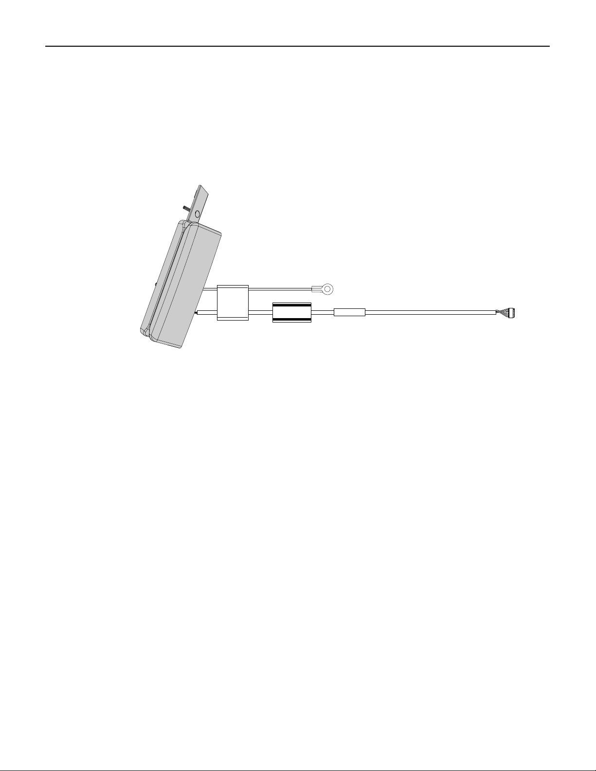
32013
MSR
9
7. Insert the cables into the opening in the chassis and install the MSR Assembly in
the slots of the cabinet.
8. Secure the MSR to the chassis (2 screws).
Page 12

10
26691
MSR Data Cable
MSR Ground Cable
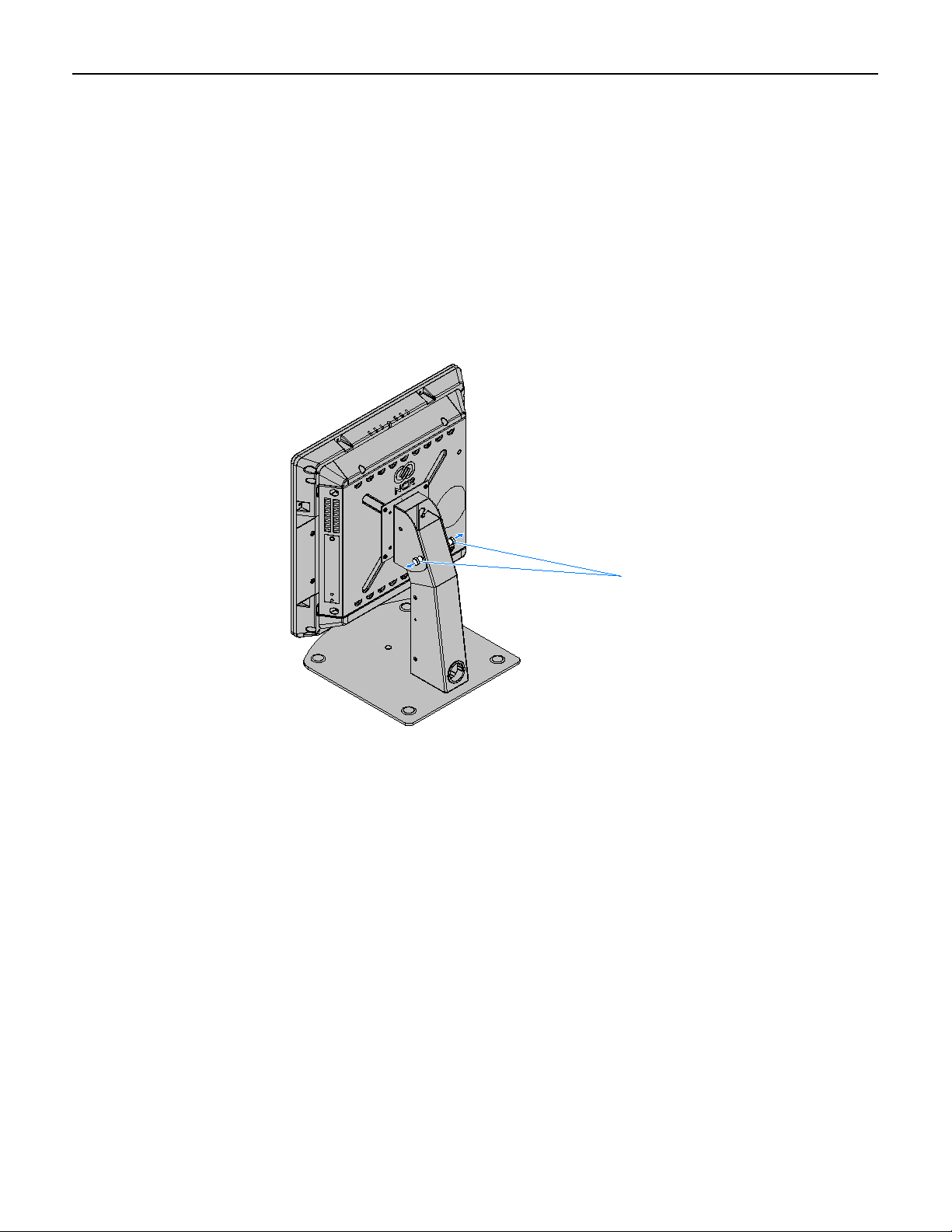
9. Connect the MSR USB Cable to the I/O Board.
10. Connect the MSR Ground Cable to the chassis (screw).
11. Replace the Rear Cover and mount the Display Head to its mount using the
reverse procedures.
Page 13

MSR Programming
If the MSR Module (ISO) is replaced the customer is responsible for re-programming
the device to custom wedge-emulation parameters, using the NCR MSR
Configuration Utility, which is available on the NCR website at:
11
http://www.ncr.com
1. At this site, select the Support tab.
2. Select Drivers and Patches → Retail Support Files → NCR RealPOS and
SelfServ Terminal and Operating Systems → NCR RealPOS 25 (7610) →
Windows →[Operating System].
3. Select the MSR Configuration Utility.
For information about how to use the utility see the NCR MSR Configuration Utility
User Guide (B005-0000-2031).
 Loading...