

Page 1

NCR 7890 Presentation Scanner
User’s Guide
BD20-0901-A
Release G
November 1998
Page 2

The product described in this book is a licensed product of NCR Corporation.
Trademark Information
It is the policy of NCR Corporation (NCR) to improve products as new technology,
components, software, and firmware become available. NCR, therefore, reserves the right to
change specifications without prior notice.
All features, functions, and operations described herein may not be marketed by NCR in all
parts of the world. In some instances, photographs are of equipment prototypes. Therefore,
before using this document, consult with your NCR representative or NCR office for
information that is applicable and current.
To maintain the quality of our publications, we need your comments on the accuracy,
clarity, organization, and value of this book.
Address correspondence to:
Retail Systems Group−Atlanta
NCR Corporation
2651 Satellite Blvd.
Duluth, GA 30136
Copyright © 1997
By NCR Corporation
Dayton , Ohio U.S. A.
All Rights Reserved
Page 3

About this Book
Further Information
Preface
This book is for t h e v a riou s people who un p ack, insta ll,
program, operate, and troubleshoot the NCR 7890
Presentation Scanner. It contains step-by-step
instructions for each of these functions.
Since the daily operation of the scanner is very simple,
frequent references t o t h is book are not required while
using t h e s ca n n er. However, this book is essential e ach
time you perform the less frequently used functions
such as in stalling an d p rogramming.
You can obtain additional information about the NCR
7890 Presentation Scanner by contacting your NCR
representative. The following list identifies the available
information products.
• NCR 7890 Presentation Scanner Repair Guide
(BD20-0902-A)
• NCR Scanner Programming Tags (BST0-2121-74)
• NCR Scanner/Scale Interface Programmer ’s Gu ide
(BD20-1074-A)
• NCR 7890-0100 Parts Identification Manual
(BUF0-177)
• NCR 7890-0200 Parts Identification Manual
(BUF0-644)
Note: The Programming Tags book (BST0-2121-74) is
included with t h is documen t and with the R e pair Guide
(BD20-0902-A).
User’s Guide i
Page 4

Preface
Information Products are available through several
different channels. F or fa x , e-mail, or ma il order, an
NCR Information Products order form is available to
NCR person ne l throug h Quick Look
Web Site
• http://inforetail.AtlantaGA.NCR.COM (NCR only)
• http://www.info.NCR.COM (Anyone)
Online Order
• Connect System (NCR only)
Phone Order
• 800-543-2010 (US area)
• 622-3727 (VOICEplus)
• 44-181-242-5350 (International)
Fax Order
• 937-445-6245 (US area)
• 44-181-242-5355 (International)
E-Mail
• Information+Products.Publishing@DaytonOH.NCR.
COM (US area)
• Management.Order@UnitedKingdom.NCR.COM
(International)
MS-Mail
• Publishing, Information+Products (US Area)
SMTP
• Order, Management UnitedK (International)
Mail Order
• NCR Corporation IPP-Dayton1700 S. Patters on
BoulevardDayton, OH 45479 USA
• NCR Corporation915 High RoadNorth
FinchleyLondon N12 OHN United Kingdom
ii User’s Guide
Page 5

Contents
Chapter 1
Introducing the 7890 Scanner
The NCR 7890 Presentation Scanner .......................... 1-1
Using Your Scanner ................................................ 1-3
Laser Scanning ....................................................... 1-4
Chapter 2
Site Requirements for Yo ur 7890 Scanner
Understanding Your 7890 Scanner
Requirements ................................................................ 2-1
Physical Considerations ........................................ 2-1
Environmental Considerations ............................. 2-3
Power Considerations ............................................ 2-4
Scanner Location .................................................... 2-4
Chapter 3
Installing Your 7890 Scanner
Installing Your 7890 Scanner ....................................... 3-1
Overview ................................................................. 3-1
Preparing for Installation ...................................... 3-1
Insta llin g t h e Sca n n e r ............................................ 3-2
Preparing for Installation ............................................. 3-3
What is in the Box .................................................. 3-3
Reporting a Damaged Scanner ............................. 3-3
ESC/POS Read Me First iii
Page 6

Contents
Interpreting the 7890 Product Number ................ 3-4
Identifying Scanner Module Cables ...................... 3-4
Identifying Interface Cables .................................. 3-5
Determining Scanner Location .............................. 3-6
Identifying Available Kits ...................................... 3-7
Determining the Communication
Protocol .................................................................... 3-9
Insta llin g t h e Sca n n e r ................................................. 3-11
Connecting the Scanner Module Cable .............. 3-12
Connecting the Power Module ........................... 3-12
Modifying the Scanner Program ......................... 3-13
Connecting the Interface Cable ........................... 3-13
Chapter 4
Operating Your 7890 Scanner
The 7890 Scanner Components ................................... 4-1
Presentation Scanning .................................................. 4-2
Pick-Up Scanning ......................................................... 4-5
Label Orientation .......................................................... 4-6
Scan Pattern Location ............................................. 4-6
Label Rotation ......................................................... 4-7
Distance from Scanner ........................................... 4-8
Read Indicators ............................................................. 4-9
Status Indicator ....................................................... 4-9
Audible Indicator ................................................... 4-9
Indicator Functions .............................................. 4-10
Bar Code Quality ........................................................ 4-11
Taking Care of Your Scanner ...................................... 4-13
Scanner Operation Summary .................................... 4-14
1 Scan the Bar Code Label .................................... 4-14
2 Observe the Read Indication ............................ 4-14
iv ESC/POS Read Me First
Page 7

Contents
Chapter 5
Programming Your 7890 Scanner
Overview - Programming Your Scanner .................... 5-1
Preparing for Your Program ................................. 5-1
Completing the Worksheets .................................. 5-1
Entering Your Program .......................................... 5-2
Requirements .......................................................... 5-2
Helps ....................................................................... 5-2
Suggestion .............................................................. 5-2
Programming Considerations ..................................... 5-3
Programming Worksheets ..................................... 5-3
Programming Tags ................................................. 5-3
Programming Mode ............................................... 5-5
Entering Your Program ................................................ 5-6
Communications Protocol ........................................... 5-7
Protocol ................................................................... 5-7
Sample Program ..................................................... 5-8
Entering the Program ............................................ 5-8
Good Read Tone ......................................................... 5-10
Tone On/Off ......................................................... 5-10
Tone Frequency .................................................... 5-10
Tone Length ........................................................... 5-11
Parameter Shortcuts .............................................. 5-11
Sample Program ................................................... 5-12
Entering the Program .......................................... 5-12
Timers .......................................................................... 5-16
Lockout Time ........................................................ 5-16
Restart Lockout Timer ......................................... 5-16
Active Time ........................................................... 5-17
Multiplier .............................................................. 5-17
Parameter Shortcuts ............................................. 5-18
Sample Program ................................................... 5-18
Entering the Program .......................................... 5-19
Bar Codes - 1 ............................................................... 5-22
Code 128 ................................................................ 5-22
ESC/POS Read Me First v
Page 8

Contents
UPC/EAN ............................................................. 5-22
Parameter Shortcuts ............................................. 5-25
Sample Program ................................................... 5-25
Entering the Program ........................................... 5-26
Bar Codes - 2 ............................................................... 5-32
Code 39 .................................................................. 5-32
Parameter Shortcuts ............................................. 5-33
Sample Program ................................................... 5-34
Entering the Program ........................................... 5-35
Bar Codes - 3 ............................................................... 5-39
Interleaved 2 of 5 .................................................. 5-39
Parameter Shortcuts ............................................. 5-41
Sample Program ................................................... 5-41
Entering the Program ........................................... 5-42
Bar Codes - 4 ............................................................... 5-47
Code 128 ................................................................ 5-47
Minimum Data Characters Allowed ................... 5-47
UCC 128 ................................................................ 5-48
Parameter Shortcuts ............................................. 5-48
Sample Program ................................................... 5-49
Entering the Program ........................................... 5-50
Label Identifiers .......................................................... 5-52
Identifier Type ....................................................... 5-52
Common Byte 1 and Common Byte 2 ................ 5-55
Bar Code Type ....................................................... 5-55
Common Byte ....................................................... 5-56
Unique Identifier .................................................. 5-56
Version Number .................................................... 5-57
Parameter Shortcuts ............................................. 5-57
Sample Program ................................................... 5-58
Entering the Program ........................................... 5-59
Additional Bar Code Options .................................... 5-66
UPC Number System Character ......................... 5-66
Sample Program ................................................... 5-66
Entering the Program ........................................... 5-67
vi ESC/POS Read Me First
Page 9

Contents
RS-232 Parameters - 1 ................................................. 5-68
Baud Rate .............................................................. 5-68
Parity ..................................................................... 5-68
Stop Bits and Character Length .......................... 5-68
Handshake ............................................................ 5-69
Parameter Shortcuts ............................................. 5-70
Sample Program ................................................... 5-70
Entering the Program .......................................... 5-71
RS-232 Parameters - 2 ................................................. 5-74
BCC Option .......................................................... 5-74
Interface Control ................................................... 5-74
Check Digit ........................................................... 5-75
VLI and Bit 6 EOM ............................................... 5-75
Retransmit on ACK/NAK Timer
Expiration ............................................................. 5-76
Parameter Shortcuts ............................................. 5-76
Sample Program ................................................... 5-77
Entering the Program .......................................... 5-78
RS-232 Prefix Byte ...................................................... 5-81
Prefix Byte ............................................................. 5-81
ASCII Code ........................................................... 5-81
Parameter Shortcuts ............................................. 5-81
Sample Program ................................................... 5-82
Entering the Program .......................................... 5-82
RS-232 Term inator By te .............................................. 5-85
Terminator Byte .................................................... 5-85
ASCII Code ........................................................... 5-85
Parameter Shortcuts ............................................. 5-86
Sample Program ................................................... 5-86
Entering the Program .......................................... 5-86
Communications Options .......................................... 5-89
Send IBM Tags in Hex or ASCII .......................... 5-89
Maintain or Drop OCIA Tag Message
Data ....................................................................... 5-89
Retries on IBM Message ...................................... 5-90
ESC/POS Read Me First vii
Page 10

Contents
RS-232 Mode: Normal or Eavesdrop .................. 5-90
RS-232 Delay ......................................................... 5-91
OCIA NCR Short Soft Rest .................................. 5-91
Sample Program ................................................... 5-92
Entering the Program ........................................... 5-93
Clone Programming ................................................... 5-95
Scanner Programming Summary .............................. 5-97
Creating the program ........................................... 5-97
Entering the Program ........................................... 5-98
Saving the Program .............................................. 5-99
Cloning the Program ............................................ 5-99
Chapter 6
Troubleshoo ting Your 7890 Scanner
Fault Identification ....................................................... 6-1
Repairing Your 7890 Scanner ....................................... 6-4
Interface Switch ............................................................. 6-5
Switch Function ...................................................... 6-5
Changing the Interface Switch Setting ................. 6-6
Fuse ................................................................................ 6-7
Appendix A
Programming Worksheets
Overview - Programming Worksheets ...................... A-1
Purpose ................................................................... A-1
Format .................................................................... A-1
Defaults .................................................................. A-1
Shortcuts ................................................................. A-2
ASCII Characters ................................................... A-2
Program Entry ....................................................... A-2
viii ESC/POS Read Me First
Page 11

Radio Frequency Interference
Statement
Federal Communications Commission (FCC)
Note:
Information to User:
This equipment has been tested and found to comply
with the limits for a Class A digital device, pursuant to
Part 15 of the FCC Rules. Th es e limits are designed to
provide reasonable protection against harmful
interference when the equipment is operated in a
commercial environment. This equipment generates,
uses, and can radiate radio frequency energy an d, if not
installed and used in accordance with out the
instruction manual, may caus e harmful inte rference to
radio communications. Op eration of th is eq u ipm en t in a
residential area is likely to ca u se harmfu l in t e rferen ce in
which case the user is required to correct the
interference at his own expense.
This equipment must be installed and used in strict
accordance with the manufa ct u rer’s instru ctio n s.
However, there is no guarantee that interference to
radio communica tion s will not occur in a p a rticu la r
commercial insta lla tion . If this eq u ipment does cause
interference, wh ich ca n be de t ermined by tu rn ing the
equipment off and on, the user is encourag ed to consu lt
an NCR Corporation service representative
immediately.
User’s Guide ix
Page 12

Radio Frequency Interference Statement
Caution:
NCR Corporation is n ot respon s ible for any radio or
television interference caused by unauthorized
modifications of this equipment or the substitution or
attachment of connecting cables and equipment other
than those specified by NCR. Such unauthorized
modifications, substitutions, or attachments may void
the user’s authority to operate the equipment. The
correction of interferences caused by su ch u nau th orized
modifications, substitutions, or attachments are the
responsibility of th e u s e r.
Voluntary C o ntrol C o uncil fo r Interference
(VCCI) Radio Frequency Interference Statement
x User’s Guide
Page 13

Canadian Department of Communications
Radio Frequency Interference Statement
This digital apparatus does not exceed the Class A
limits for radio noise emissions from digital apparatus
set out in the Radio Interference Regulations of the
Canadian Department of Communication.
Le présent appareil numérique n’émet pas de bruits
radioélectrique s d épassan t le s limites ap plicables aux
appareils numériques de la Class A prescrites dans le
Règleme n t sur le brouillage rad ioéle ctriq u e s édicté par
Ministère des Communications du Canada.
Safety Extra Low Voltage
This device should only be powered by a Safety Extra
Low Volta g e (SELV) power supp ly source with an
available current level of 5 amperes or less, suitable for
the country of installation. The power source must be
certified by the appropriate safety agency for the
country of installation.
Le matériel doit être reliés electriquement au circuit å
Très Bas s e Tension de Sécurité (TBTS) ayant une limite
de 5 ampères correspondant de facon satisfaisante et
acceptable dan s le pays où le m a t érie l doit ê tre installé.
Le source d’alimentation doit être approuvée par une
agence de normalisation appropriée et acceptable dans
le pays où le matériel doit être installé.
User’s Guide xi
Page 14

Declaration of Conformity
Declaration of C onformity
Manufacturer’s Name
Manufacturer’s
Address
Type of Equipment
Model Number
Electrical Rating (Input)
NCR Corporation
NCR Corporation
Retail Systems Group - Atlanta
2651 Satellite Boulevard
Duluth, GA 30136
Information Technology Equipment —
Presentation Scanner
Class 7890
9 Vdc, 1.0 A
NCR Corporation, 1700 South Patterson Bou levard,
Dayton, OH 45459, USA, declares that the equipment
specified above conforms to the referenced
EU Directives and Harmonized Standards.
EU Directive Harmonized Standard(s) File, Certificate,
89/336/EEC (EMC) EN 55022: 1987 (CISPR 22)
EN 50082-1, Part 1: 1992
IEC 801-2: 1984
IEC 801-3: 1984
IEC 801-4: 1988
or Test Report
Number
00334
xii User’s Guide
Director of Qua lity A ssur ance
NCR Corporation
Retail Sys te m s G roup - Atlanta
2651 Satellite Boulevard
Duluth, GA 30136
Page 15

European Contact:
NCR Limited
206 Marylebone Road
London, NW1 6LY, Eng land
User’s Guide xiii
Page 16

Declaration of Conformity
xiv User’s Guide
Page 17

Laser Safety Label
Figure 1
7890 Product Label (Laser Safety)
Laser Safety
The NCR 7890 Presentation Scanner comes from the
factory with the Laser Safety label attached. The
following figure s h ows t h e La s e r Sa fet y la bel a n d its
location.
Complies with FDA radiation
Corporation
NCR
Atlanta, G A 30136
perform ance standards, 21
CF R S ubchapter J
Made in USA
R
D ate M anufactured
C lass 7890
Model
9A 1
V
DC
Covered by one or m ore of the follow ing patents or patents pending: 4935610, 4971410,
5105070, 51 32523, 5148009, 5155346, 5164584, 5179271, 5185514, 5195514, 5198650,
5206776, 52 21832, 5256865
Class IIa Laser Product.
Avoid Long-Term V iew ing
of direct Laser Light.
Serial
Tracer
W 9
Funkenstört nash VF G 243/91
Ap pareil á laser de classe IIa.
Éviter toute exposition prolongée
de la vue à la lum ière laser directe.
EN -60825-1 CLA SS 1 LA SE R P RO DUCT
"This device complies with part 15 of the FC C Rules
Operation is subject to the following two conditions
(1) T his device may not cause harmful intreference
and (2) this device m ust accept any interference
received includin g interference that ma y cause
undersired operation"
CA
This apparatus does not exceed the
C la s s A lim it s fo r ra d io n o is e
emm isio ns set out in the Radio
interference R egulation of Canada
Le presént appareil ñ em et pas de
bruits radioélectrictriques dépassant
le s lim ite s d e la c la s s é A p re s c r ite s
dans le Reglement sur le bro uilage
radioélectricque du Canada.
Clase IIa Produto Laser.Traté
de no ver directam ente él Rayo
Laser por muchó tiem po.
12188
Repair Guide xv
Page 18

Laser Safety
Country Language
Specific ICE Class 1
Laser Labels
Figure 2
Country Language Specific IE C
Class 1 Laser Labels
There are seven Country Language Specific IEC Class 1
Laser labels included with the NCR 7890 Scanner when
configured for international installations. The
importer/installer must attach the correct IEC label to
the scanner cabinet. The following figure shows the
labels and suggested installation location.
CLASS 1 LASER
PRODUCT
APPAREIL A LASER
DE CLASSE 1
PRODUCTO LASER
CLASE 1
LUOKAN 1
LASERELAITE
KLASS 1
LASER APPARAT
LASER KLASSE 1
Zeitbasis 100 s
12187
xvi Repair Guide
Page 19
7890 0100 Laser
Module Label
Location
CAUTION: Laser
radiation when
open and interlock
defeated.
DO NOT STARE
INTO BEAM.
This laser module
does not comply
with 21CFR1040.
USE ONLY AS A
Component.
7890 0200 Laser
Module Label
Location
CAUTION: Laser
radiation when
open and interlock
defeated.
DO NO T STARE
INTO BEAM.
This laser module
does not comply
with 21CFR1040.
USE ONLY AS A
Component.
CAUTION: Laser
radiation when
open and interlock
defeated.
DO NOT STARE
INTO BEAM.
This laser module
does not comply
with 21CFR1040.
USE ONLY AS A
Component.
12189
CAUTION: Laser
radiation when
open and interlock
defeated.
DO NOT STARE
INTO BE AM.
This laser module
does not comply
with 21CFR1040.
USE ONLY AS A
Component.
15710
Repair Guide xvii
Page 20

Laser Safety
Laser Power
The NCR 7890 Presentation Scanner meets the following
laser/LED power requirements.
• Class IIa CDRH (Center for Devices and
Radiological Health)
“Class IIa Laser Product—Avoid Long-Term
Viewing of Direct Laser Light.”
• Class 1 EN60-825 (Europäische Norm)
Following is t h e ra dia n t en e rgy of t h e la ser/LED lig h t
as applied to each of the specified requirements.
7890-0100
Accessible Emission Limit (CDRH Calculation) 0.66 Milliwatts
Accessible Emission Limit EN60 8251:1994+AII:1996
0.63 Milliwatts
7890-0200
Accessible Emission Limit (CDRH Calculation) 0.99 Milliwatts
Accessible Emission Limit EN60 8251:1994+AII:1996
7890-8082
Accessible Emission Limit (CDRH Calculation) 0.99 Milliwatts
Caution: Use of controls or adjustments or performance
of procedures other tha n s pecified herein may resu lt in
hazardous radiation exposure.
Class IIa Laser Product--Avoid Long-Term Viewing of
Direct Laser Light.
xviii Repair Guide
0.81 Milliwatts
Page 21

Revision Record
Chapter 1 - Introducing t h e 7890 S cann er
Page No. Date Remarks
1-1 - 1-6 07/92 First printing.
1-1 - 1-6 01/96 Changed product name.
1-1 - 1-4 03/97 Incorporated 7890 0200
Scanner Information.
Chapter 2 - Site Requirements for Your 7890 Scanner
Page No. Date Remarks
2-1 - 2-4 07/92 First printing.
2-3 03/93 Acoustical Noise was
lowered.
User’s Guide xix
Page 22

Revision Record
Chapter 3 - Installing Your 7890 Scanner
Page No. Date Remarks
3-1 - 3-8 07/92 First printing.
3-1 - 3-12 03/93
3-1 - 3-14 03/94
3-3, 3-13
01/96 Changed product name
3-4, 3-5
3-8
3-1 - 3-14 03/97
Added an Overview.
Added new cables.
Added new kits.
Added section on
determining the
communication protocol.
Added new cables
Added new kits
Changed Communications
Protocol table
Updated cable charts.
Updated kit chart.
Incorporated 7890 0200
Scanner Information.
Updated Cable and kit
charts.
xx User’s Guide
Page 23

Chapter 4 - Operating Yo ur 7890 Scanner
Page No. Date Remarks
4-1 - 4-16 07/92 First printing.
4-1 - 4-16 03/93 Revised description of
presenta t io n s canning.
Revised description of read
indicators.
Revised the Summary.
4-1 - 4-18 03/94 Added information to 4-14
4-3, 4-4 01/96 Updated illustrations.
4-1 - 4-16 03/97 Incorporated 7890 0200
Scanner Information.
Chapter 5 - Programming Your 7890 Scanner
Page No. Date Remarks
5-1 - 5-74 07/92 First printing.
5-1 - 5-91 03/93 Complete revision of this
chapter.
5-7,40,56,
67-69,73,
74,76,84,85
03/94 Changes to these pages
5-88 - 91
Added Communications
Options section on pages
88-91
5-2, 5-3
01/96 Changed order number of
Programming Tags book.
5-66, 5-67
Added Additional Bar
Code Options
programming parameters
description.
User’s Guide xxi
Page 24

Revision Record
Page No. Date Remarks
5-91
5-92
5-1 - 5-100
5-33
5-91
5-95
Added RS-232 Delay
parameter description.
Added Sample Program.
for Communications
Options parameter
description.
03/97 Incorporated 7890 0200
Scanner Information.
Added Allow Single
Character Tags parameter
description.
Added OCIA NCR Short
Soft Reset parameter
description.
Updated Clone
Programming description.
xxii User’s Guide
Page 25

Chapter 6 - Troubleshooting Your 7890 Scanner
Page No. Date Remarks
6-1 - 6-6 07/92 First printing.
6-1 - 6-7 03/93 Enhanced troubleshooting
chart.
Changed Factory Repair to
Repairing Your 7890 Scanner
and revised section.
Revised description of
Interface Switch.
6-3 03/94 Change to this page
Appendix A - Programming Worksheets
Page No. Date Rem ar ks
A-1 - A-14 07/92 First printing.
A-1 - A-17 03/93
Revised Overview.
Added Defaults chart.
Revised Timeouts.
Revised Bar Codes - 1.
Revised Bar Codes - 3.
Added Bar Codes - 4.
Revised RS-232 Parameters -
2.
A-1 - A-18 03/94
Changed Bar Codes - 1 value
on page A-3
Changed page A-5
Changed Character 2 default
on page A-10
Added Communications
Options section on page A-17
User’s Guide xxiii
Page 26

Revision Record
Page No. Date Rem ar ks
A-14
01/96 Added Additional Bar Code
Options programming
worksheet.
A-19
Added RS-232 Delay
parameter.
A-1 - A-20
03/97
Incorporated 7890 0200
Scanner Information.
A-9
Updated Bar Codes - 1
Worksheet
A-10
A-19
Updated Bar Codes - 2
Worksheet
Updated Communications
Options Worksheet
Index
Page No. Date Remarks
I-1 - I-7 07/92 First printing.
I-1 - I-9 03/93 Revised to reflect all
changes made to this book.
I-1 - I-9 03/94 Revised to reflect this
revision.
I-1 - I-10 01/96 Revised to reflect this
revision.
I-1 - I-8 03/97 Revised to reflect this
revision.
xxiv User’s Guide
Page 27

User’s Guide xxv
Page 28

Contents
Chapter 1
Introducing the 7890 Scanner
The NCR 7890 Presentation Scanner .......................... 1-1
Using Your Scanner ................................................ 1-3
Laser Scanning ....................................................... 1-4
Book Title i
Page 29

Contents
ii Book Title
Page 30

Operating Your 7890 Scanner
The NCR 7890 Presentation Scanner
The NCR 7890 Pre s entation
Scanner
Your new scanner represents the latest technology in
laser scanning. Being a presentation scanner, you
present the label to the scanner. This eliminates the need
of moving the label past the scan window, reducing the
amount of operator activity.
The 7890 Presentation Scanner is a small, compact unit
that weighs less than two pounds. Figure 1-1 shows the
scanner, connecting cables, and power module.
User’s Guide 1-1
Page 31

Operating Your 7890 Scanner
The NCR 7890 Presentation Scanner
Figure 1-1
NCR 7890 Presentation Scanner
7890 Scanner
Scanner M odule C able
In te rfa c e C a b le
Pow er M odule
R0 002
1-2 User’s Guide
Page 32

Using Your Scanner
Operating Your 7890 Scanner
The NCR 7890 Presentation Scanner
Because your NCR 7890 scanner is a hands-free
presentation type scanner, it is much easier to use in
the retail environment. The scanner sits on the
counter a n d you present the bar code label to the
scanner. By using an optional Holder, you can hang
the scanner on a wall, or define a space on the
counter top, depending on the construction of your
checkout area.
Although the 7890 is a presentation scanner, there
may be times when the merchandise is too large to be
presented to the scanner. In these cases, you ca n pick
up the scanner and move it to the merchandise.
Because the scanner is very light, you can maneuver
it easily in these circumstances.
The design of your scann er permits it to sit on a
counter top in either a horizontal or vertical position.
However, you may want to use a Holder to prevent
the scanner from moving. The optional Holder kit
contains three different Holders: horizontal mount,
vertical mount, and hanging mount. You fasten the
Holders that you want to use to the counter top or an
adjacent wall. The Holders keep the scanner in a
position that is comfortable to use.
Your 7890 Presentation Scanner does not have an
On/Off switch. To minimize the amount of time the
laser is on, and to reduce wear in the u nit, the
scanner contains circuitry that turns it off when no t
in use. If you present a label to the scanner when it is
off, it detects the obj e ct and turns on. This occurs
with no noticeable delay in re ading the label. After
several seconds of not det ecting a v alid bar code , the
scanner shuts off.
User’s Guide 1-3
Page 33

Operating Your 7890 Scanner
The NCR 7890 Presentation Scanner
Laser Sca nni ng
Although the 7890 Presentation Scanner is very
simple to use, it is quit e a complex electronic device.
It contains a laser m odule that generate s a low-level
laser light. The laser light passes through a se rie s o f
mirrors to ge n erate a scan pattern . A deflector mirror
directs the light out the scan window. Reflected light
from the b ar code is collecte d and decoded to
determine the bar code data. The scanne r then sends
the information to the host terminal or personal
computer (PC).
The 7890 Presentation Scanner produces an
omnidirection al scan pattern that makes scannin g
easier. T he pattern looks like several lines are
scanning simultaneously, but is actually just a single
beam re flected through several mirrors. It is th is
pattern that enables the scanner to read bar codes
from most orientations.
After reading the information contained in the bar code,
the 7890 sends the information to the host terminal or
personal computer (PC). In terfaces available for
transmitting information are OCIA NCR Long, OCI A
NCR Short, OCIA Non-NCR, RS-232, and IBM
468x/469x. The 7890 Presentation Scanner contains all
the necessary electronics and firmware for each of these
interfaces. When ins t a llin g t h e scanner yo u can change
the interface selection if needed. Refer to Chapter 5,
Programming Your 7890 Scanner and Chapter 6,
Troubleshooting Your 7890 Scanner.
1-4 User’s Guide
Page 34

Contents
Chapter 2
Site Requirements for Yo ur 7890 Scanner
Understanding Your 7890 Scanner
Requirements ................................................................ 2-1
Physical Considerations ....................................... 2-1
Environmental Considerations ............................ 2-3
Power Considerations ............................................ 2-4
Scanner Location .................................................... 2-4
User’s Guide i
Page 35

Contents
ii User’s Guide
Page 36

Physical
Considerations
Site Requirements f or Your 7890 Scanner
Understanding Your 7890 Scanner Requirements
Understanding Your 7890
Scanner Requirements
Your 7890 Presentation Scanner is designed to operate
within a wide environm ental range. Being a s mall
periphera l u n it , it do es not require any special wiring or
mounting . Normally, its requ iremen t s a re within t h os e
of the host terminal or PC.
The 7890 Presentation Scanner is a small, light-weight
unit. Weighing less than two pounds, it is remarkably
easy to pick up when necessary. When sitting on the
counter top it can be placed in either a horizontal or
vertical position. Each of these positions require
minimal counter space. Figure 2-1 shows the scanner
dimensions when sitting on a counter top.
Horizontal
Vertical
User’s Guide 2-1
6.1 in. x 6.1 in. (15.6 cm x 15. 6 c m)
3.6 in. x 5.4 in. (9.1 cm x 13. 7 c m)
Page 37

Site Requirements f or Your 7890 Scanner
Understanding Your 7890 Scanner Requirements
Figure 2-1
7890 Physical Dimensi ons
H orizontal P osition
6.1 in.
( 1 5 .6 c m )
4.2 in.
( 1 0 .8 c m )
6.1 in.
( 1 5 .6 c m )
Vertical Position
3.6 in.
( 9.1 cm )
2-2 User’s Guide
6.1 in.
( 1 5 .6 c m )
5.4 in.
( 1 3 .7 c m )
R 0005
Page 38

Environmental
Considerations
Site Requirements f or Your 7890 Scanner
Understanding Your 7890 Scanner Requirements
Your 7890 Presentation Scanner operates in all standard
working environments. Temperature and humidity
ranges permitted are greater when the 7890 is in storage
or transit. The following table gives the various
environmental requirements.
Working Range Storage Range
Temperature
Temperature
Change
Humidity
Humidity Change
50°F to 104°F
10°C to 40°C
18°F per hour
10°C per hour
20% to 80% RH
Non-Condensing
10% per hour
-40°F to 140°F
-40°C to 60°C
36°F per hour
20°C per hour
5% to 95% RH
Non-Condensing
Barometric
Pressure
Ambient Light
Acoustical Noise
Vibration and
Shock
105 x 103 Pa
to 69 x 103 Pa
300 Foot-candles
on tag, s canner
not pointed at
light source
50 dBa or less
measured at 12 in.
(30.48 cm) from
any surface
Can withstand multiple 36-in. (91.44cm) drops onto a tiled concrete floor
Not Applicable
Not Applicable
User’s Guide 2-3
Page 39

Site Requirements f or Your 7890 Scanner
Understanding Your 7890 Scanner Requirements
Your 7890 Presentation Scanner operates on only 9
Power Considerations
Vdc. It receives current through the Scanner Module
Cable, from a power module that plugs into an
electrical outlet. One of four power modules comes
with your scanner, depending on the requirements
you specify. It is critical that you have the proper
power module for your elect rical circuit. Th e following
power modules are available.
• 104 Vac to 127 Vac, 60 Hz, USA/Canada
• 220 Vac to 240 Vac, 50 Hz, European
• 220 Vac to 240 Vac, 50 Hz, Au s tralia
• 90 Vac to 104 Vac, 50/60 Hz, Japan
When identifying a location for your 7890 Scanner,
Scanner Location
consider t h e le n gth of the co n n e ct in g ca ble s . The
electrical outlet used for the Power Module can be
approximately 74 in. (188 cm) from the host terminal.
Depending on the Scanner Module Cable, the scanner
can be approximately 6.6 ft (2 M) or 13.1 ft (4 M) from
the host terminal or PC. These distances are normally
shorter depending on how you route the connecting
cables. Be sure that the Scanner Module Cable is long
enough to permit the scanner to be picked up when
required for large packages .
2-4 User’s Guide
Like any electronic device, your 7890 Presentation
Scanner sh ou ld n ot be loca t ed in direct s u nlight.
Temp eratu res above 104 degrees Fahrenheit (40 degrees
Celsius ) ca n occu r wh e n sunlight falls on objects
through windows or on an ou tdoor checkstand.
Page 40

Contents
Chapter 3
Installing Your 7890 Scanner
Installing Your 7890 Scanner ....................................... 3-1
Overview ................................................................. 3-1
Preparing for Installation ...................................... 3-1
Insta llin g t h e Sca n n e r ............................................ 3-2
Preparing for Installation ............................................. 3-3
What is in the Box .................................................. 3-3
Reporting a Damaged Scanner ............................ 3-3
Interpreting the 7890 Product Number ............... 3-4
Identifying Scanner Module Cables .................... 3-4
Identifying Interface Cables ................................. 3-5
Determining Scanner Location ............................. 3-6
Identifying Available Kits ..................................... 3-7
Determining the Communication
Protocol ................................................................... 3-9
Insta llin g t h e Sca n n e r .................................................. 3-11
Connecting the Scanner Module Cable ............ 3-12
Connecting the Power Module .......................... 3-12
Modifying the Scanner Program ........................ 3-13
Connecting the Interface Cable .......................... 3-13
User’s Guide i
Page 41

Contents
ii User’s Guide
Page 42

Overview
Preparing for
Installation
Installing Your 7890 Scanner
Installing Your 7890 Scanner
Installing Your 7890 Scanner
This overview of the Installing Your 7890 Scanner is
intended to help you understand the steps necessary to
install the scanner. It identifies each of the things you
must consider to have a successful installation.
There are several things you should do when preparing
for the installation. These are listed as follows.
1 Open the box and verify that you have received
all the necessary components.
2 Inspect the scanner for damage.
3 Verify the communication protocol required by
your host terminal or PC. The 7890 comes from
the factory programmed for OCI A NCR Short.
4 Verify that you have the correct Interface Cable
for your host terminal or PC.
5 Determine where you want to locate your 7890
Scanner.
6 If you are installing a Holde r, verify tha t you
have the correct kit.
User’s Guide 3-1
Page 43

Installing Your 7890 Scanner
Installing Your 7890 Scanner
Installing the Scanner
Installing the 7890 Scan n er in volves con n ectin g all th e
cables, m aking any program chang e s , and ins ta llin g a
Holder if one is bein g used. P erform this proces s a s
follows.
7 Install the Scanner Module Cable.
8 Install the Power Module.
9 Make any necessary changes to the program.
10 Install th e Holde r if on e is be in g used.
11 Ins tall the In terface Cable to your host term inal or
PC.
3-2 User’s Guide
Page 44

What is in the Box
Installing Your 7890 Scanner
Preparing for Installation
Preparing for Installation
Before installing your NCR 7890 Presentation Scan ner,
there are some tasks that you need to perform. There is
also some information that is useful as you get ready to
install th e scanner.
After you have unpacked the 7890 Scanner according to
the instructions printed on the box, take inventory to
assure that you have received all components. The
following list ide n t ifies the pack a g e con te n t s .
• 7890 Presentation Scanner
• Power Module
• Scanner Module Cable
• Interface Cable
Reporting a Damaged
Scanner
• Documentation
The optional Holders do not come in the same box with
the scanner, but are shipped separately.
If your scanner has been damaged due to shipping,
notify the shipping carrier and your NCR
representative. If you find other damage, notify NCR, or
other sup p lie r if n ot purchased directly from NCR .
User’s Guide 3-3
Page 45

Installing Your 7890 Scanner
Preparing for Installation
Interpreting the 7890
Product Number
Currently, there are two models of the 7890 Presentation
Scanner that can be configured with one of four
different Power Modules. Figure 3-1 shows the
interpretation of the 7890 Product Number.
Figure 3-1
Product Number
Identifying Scanner
Module Cables
90X X
C lass: 7890
M ajor M odel: 01 (O nly O ne A vailable)
Sub M odel: 00 (None)
Power:
00 = 104-127 Vac, 60 H z, U S /C anada
25 = 220-240 Vac, 50 H z, European
26 = 220-240 Vac, 50 H z, Australia
62 = 90-104 Vac, 50/60 H z, Japan
Language: 90 (N o Characteristics)
7890 0100--
There are three available Scanner Module Cables. The
following chart gives the Corporate ID Num ber for
each.
Scanner Module Cable
Cable Descripti o n
2-Meter, Straight 1416-C047-0020
4-Meter, Straight 1416-C034-0040
3-Meter, Coiled 1416-C124-0030
Checkpoint EAS 1416-C242-0020
Checkpoint EAS with
Interlock
Corporate ID Nu mber
1416-C353-0030
R 0007
3-4 User’s Guide
Page 46

Identifying Interface
Cables
Installing Your 7890 Scanner
Preparing for Installation
The following table ide n tifie s the interface cable
required for the different host connections that can be
made with 7890 Presentation Scanner
Interface Cable
Host Connection Interface
2122 OCIA 1416-C046-0004
2123 OCIA 1417-C024-0004
2126 OCIA 1417-C022-0004
2127 OCIA 1417-C023-0004
2151/2152 OCIA 1417-C026-0004
2155/2157 OCIA 1417-C025-0004
2552/2557 OCIA 1417-C019-0004
7050/7051 OCIA 1417-C025-0004
7052/7053/7054/7450 OCIA 1417-C020-0014
7058 OCIA 1417-C024-0004
Beetle RS-232 1416-C271-0004
Dynakey Wedge 1416-C309-0012
Fujitsu Atrium 28-Pin RS-232 1416-C201-0005
Gilbarco 9-Pin RS-232 1416-C256-0004
Verifone RS-232 1416-C272-0004
Wayne Controller RS-232 1416-C257-0004
IBM 468x Port 5B IBM 468x 1416-C024-0004
IBM 468x Port 9B IBM 468x 1416-C023-0004
IBM 468x Port 9B
(Remote Power)
IBM 468x Port 17 IBM 468x 1417-C021-0004
Non NCR OCIA OCIA 1416-C050-0004
RS-232 2170 RS-232 1416-C039-0004
RS-232 Wedge RS-232 1416-C038-0004
IBM 468x 1416-C354-0004
Corporate ID No .
User’s Guide 3-5
Page 47

Installing Your 7890 Scanner
Note:
Note:
Preparing for Installation
Determining Scanner
Location
Interface Cable
Host Connection Interface
RS-232 9-Pin RS-232 1416-C037-0004
RS-232 25-Pin RS-232 1416-C247-0004
RS-232 Eavesdrop RS-232 1416-C122-0004
RS-232 Omni-Link RS-232 1416-C200-0004
Corporate ID No .
You can also interface your 7890 Scanner to
other host terminals not shown in the previous list.
You norm ally do this by using R S -2 32
communications through a keyboard wedge. Your
application m a y a ls o requ ire a s oft wa re wedg e .
When identifying where to locate your 7890
Presentation Scanner, be sure to consider the length of
the connecting cables. The straight cables are either 6.6
ft (2 M) or 13.1 ft (4 M) long. The coil cable is 6.6 ft (2
M). You must also consider how to route the cables to
the host terminal or PC and how to route the power
cable to an electrical outlet. Within the constraints of the
cable lengths, locate the scanner in a position that is
comfortable for presenting the merchandise (labels).
Also consider a position that gives extra cable for
picking u p the scan n e r wh en requ ired for large
packages. Figure 3-2 shows the cable lengths.
3-6 User’s Guide
Do not locate scanner in direct sunlight. The
temperature may rise above the specified range
causing poor op eration or p ossible damage.
Page 48

Figure 3-2
Scanner Cables
Identifying Available
Kits
Installing Your 7890 Scanner
Preparing for Installation
H ost Term inal
In te rfa c e C a b le
Scanner M odule C able
Pow er M odule
7890 Scanner
6.6 ft
(2 m )
or
13.1 ft
(4 m )
1 5 .5 in .
(39.4 cm )
74 in.
(188 cm )
R0 006
Although it is not necessary, a Holder is very useful for
keeping the scanner from sliding around on the counter
top as you scan labels. There are four available Holder
Kits: Cup Holder, Dish Holder, Hook Holder, and
Combination (all three holders). Each of these holders
are designed to hold the scanner in a different position.
Through normal scanner use, the scan window can
become scratched. The Window Assembly is made
available in case you scratch the scan window
sufficiently to reduce the scanner’s effectiveness.
User’s Guide 3-7
Page 49

Installing Your 7890 Scanner
Preparing for Installation
A Power Module for the electrical requirements you
specified comes with the 7890 Scanner. However,
replacement Power Modules are available.
The following table identifies the kit number for each
available kit.
Kit Descripti o n Kit Number
Laser Fog Kit, Model 02 7890-K750-V001
Cup Holder 7890-K350-V001
Holder Cup with Stand 7890-K600-V001
Dish Holder 7890-K400-V001
Hook Holder 7890-K500-V001
Combination Holders (Cup, Dish, and
Hook)
Checkpoint Assembly 7890-K800-V001
Checkpoint Assembly, Model 02 7890-K802-V001
Window Assembly 7890-K200-V001
Checkpoint Window with Antenna 7890-K201-V001
Window Assembly, Model 02 7890-K205-V001
Diamonex Window Assembly,
Model 02
Power Module, 104-127 Vac, 60 Hz,
USA/Canada
Power Module, 220-240 Vac, 50 Hz,
European
Power Module, 220-240 Vac, 50 Hz,
Australia
Power Module, 90-104 Vac, 50/60 Hz,
Japan
Power Module, 240 Vac, 50 Hz, U nited
Kingdom
7890-K300-V001
7890-K206-V001
7890-K020-V001
7890-K030-V001
7890-K040-V001
7890-K010-V001
7890-K050-V001
3-8 User’s Guide
Page 50

Determining the
Communication
Protocol
Installing Your 7890 Scanner
Preparing for Installation
Kit Descripti o n Kit Number
Power Module, 104-127 Vac, 60 Hz,
USA/Canada Piggyback
Auxiliary Power C able
(7450 0xxx and 1xxx)
Auxiliary Power C able
(7450 24xx)
Auxiliary Power C able
(7452 only)
Two-Three Tag Firmware 7890-K511-V001
2123 Cable with Opto Isolator 7890-K617-V001
7890-K060-V001
7890-K070-V001
7890-K071-V001
7890-K072-V001
Before connecting your 7890 Scanner to a host terminal
or PC, you m u s t verify th e com m un ication p rotocol
being used. The 7890 comes from the factory
programmed for OCIA NCR Short; however, the
communications p rotocol is easily changed without
taking the unit apart. Refer to Ch ap ter 5, Programming
Your 7890 Scann er and C h ap ter 6, Troubleshooting Your
7890 Scanner. Also, be sure that the application program
running on your host terminal or PC can communicate
with the 7890 Scanner. Us e the following procedure if
you need to determine the communications protocol
programmed in your 7890 Scanner.
1 Apply power to the 7890 Scanner.
2 Scan the Diagno stics tag; must be first tag scanned
after applying power.
User’s Guide 3-9
Page 51

Installing Your 7890 Scanner
Preparing for Installation
3 Scan the Hex 3 tag. The good read tone for this tag
sounds (three beeps).
The Status Indicator flashes green and the tone beeps,
identifying th e com m unications p rotocol. Th e followin g
table identifies the number of beeps that sound for each
communication protocol.
Tone Communication Protocol
1 short,
high-pitched beep
(No beep on earliest
versions of t he
firmware)
1 Beep OCIA NCR Long
2 Beeps OCIA Non-NCR
3 Beeps IBM 468x - Addr 4A
4 Beeps IBM 468x - Addr 4B (1520 Bar Code
5 Beeps RS-232
6 Beeps IBM 468x - Addr 4B (Hand Held Bar
OCIA NCR Short
Reader)
Code Reader)
3-10 User’s Guide
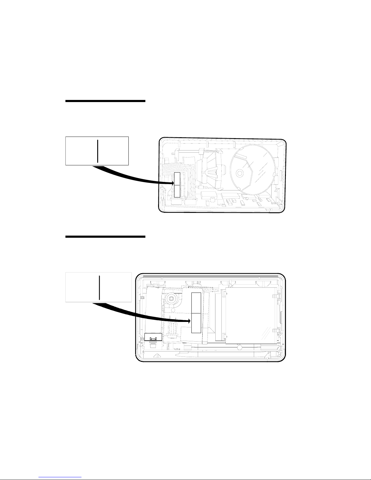
4 Remove power from the 7890 Scanner.
End of procedure.
■
Page 52

Figure 3-3
7890 Scanner Connections
Installing Your 7890 Scanner
Installing the Scanner
Installing the Scanner
The Interface Cable shipped with your 7890 Scanner
connects directly to the host terminal or PC. Since the
installation is different from one terminal to another,
you need to refer to your terminal documentation for
instructions about how to connect the Interface Cable.
Refer to the terminal and the application documentation
for specific information about the hardware and
software configuration needed to make the terminal
scanner ready. Refer to Figure 3-3 while performing the
following inst a llat ion s t e p s.
Interface C able
Scanner M odule C able
7890 Scan ner
Pow er M odule
R0 014
User’s Guide 3-11
Page 53

Installing Your 7890 Scanner
Installing the Scanner
Connecting the
Scanner Module
Cable
Connecting the
Power Module
1 Connect one en d of the Scanner Module Cable to the
7890 Scanner.
2 Connect the other end of the Scanner Module Cable
to the box on the end of the Interface Cable.
1 Verify that y ou have the correct Power Module for
your electrical outlet.
2 Connect the power connector on the end of the
Power Module Cable to the box on the end of the
Interface Cable.
3 Plug the Power Module into an electrical outlet.
When the 7890 Scanner receives power, the
diagnostics checks various hardware components. If
the scanner passes the diagnostic tests, it gives a
"ready" indication; four quick beeps of increasing
frequency and two flashes of the Status Indicator.
Does the scanner give "ready" indication?
3-12 User’s Guide
Yes
End of procedure. ■
No
Continue to Chapter 6
Troubleshooting Your 7890
Scanner ➝➝
Page 54

Modifying the
Scanner Program
Installing Your 7890 Scanner
Installing the Scanner
Your 7890 Presentation Scanner comes from the factory
with all programming parameters set to default values.
You need to change any values that do not match your
system requirements. Refer to Chapter 5, Programming
Your 7890 Scann er and Appendix A, Programming
Worksheet s.
If you have an NCR 7890 Presentation Scanner already
programmed th e way you want it to be, you can
transfer that program to another 7890 Presentation
Scanner using Clone Programming as described at the
end of Chapter 5 of this book.
If you change the comm u nication p rotocol, you m ay
need to change the Interface Switch setting. This switch
identifies the type of interface being used: OCIA, RS232, and IBM 468x. R efer to Chap ter 6, Trou bleshootin g
Your 7890 Scanner for information about the Interface
Switch.
Connecting the
Interface Cable
1 Verify that you have the correct Interface Cable.
Refer to Terminals And Cables in this chapter.
2 Connect the Interface Cable to your host terminal or
PC. Refer to the terminal documentation for these
procedures. Some terminals require a trained
technician to perform this function.
User’s Guide 3-13
Page 55

Contents
Chapter 4
Operating Your 7890 Scanner
The 7890 Scanner Components ................................... 4-1
Presentation Scanning ............................................ 4-2
Pick-Up Scanning ......................................................... 4-5
Label Orientation .......................................................... 4-6
Scan Pattern Location ........................................... 4-6
Label Rotation ......................................................... 4-7
Distance from Scanner .......................................... 4-8
Read Indicators ............................................................. 4-9
Status Indicator ...................................................... 4-9
Audible Indicator ................................................... 4-9
Indicator Functions .............................................. 4-10
Bar Code Quality ......................................................... 4-11
Taking Care of Your Scanner ..................................... 4-13
Scanner Operation Summary .................................... 4-14
1 Scan the Bar Code Label ................................... 4-14
2 Observe the Read Indication ........................ 4-14
User’s Guide i
Page 56

Contents
ii User’s Guide
Page 57

Figure 4-1
NCR 7890 Presentation Scanner
Operating Your 7890 Scanner
The 7890 Scanner Components
The 7890 Scanne r Components
Before using your 7890 Presentation Scanner, you need
to be familiar with some of its com p o n ents. F ig u re 4-1
shows the scanner and identifies some of the parts and
features.
Scanner M odule C able
Status Indicator
Scan W indow
Handle
R0 021
User’s Guide 4-1
Page 58

Operating Your 7890 Scanner
Presentation Scanning
Presentation Scanning
Presentation scanning is much different from that used
at checkout stands, such as in grocery stores. In the
checkout stand environment, normally large quantities
of items must be scanned in a short amount time.
Therefore, you pass the items over the scanner, moving
them from one side of the checkstand to another. The
scanner reads the label while the items are moving by.
With presentation scanning, you simply present the
label to the scanner and then remove it. Do not move
the label past the scanner, but to the scanner.
Presentation scanning is particularly useful in a retail
environment where the number of items associated with
each transaction is normally small. There are three
simple steps to presentation scanning.
1 Move the bar code label to the scanner as shown in
Figure 4-2. As the package approaches the scanner,
the Item Detector senses the package. If the laser
light is off, it turns on to scan the bar code. The Item
Detector emits an invisible light through the corner
of the Scan Window. If you have a small item, be
sure to initially position it to ward th e corner of the
Scan Window so it can be detected by the item
detector.
4-2 User’s Guide
Page 59

Figure 4-2
Presentation Scanning (1 of 3)
Operating Your 7890 Scanner
The 7890 Scanner Components
Ite m D e te c to r
Figure 4-3
Presentation Scanning (2 of 3)
Scan W indow
11536
2 Position the bar code label completely within the red
Laser Scan Pattern as indicated in Figure 4-3.
Normally the bar code should be three to four
inches from the scanner. When the label is read the
Status Indicator turns red, then returns to green. If
enabled, a Good Read Tone also sounds.
Laser S can Pattern
Status Indicator
11537
User’s Guide 4-3
Page 60

Operating Your 7890 Scanner
The 7890 Scanner Components
Figure 4-4
Presentation Scanning (3 of 3)
3 Move the bar code label away from the scanner as
shown in Figure 4-4. The scanner is now ready to
read another bar code label. After not detecting an
item for a period of time, the laser light turns off. To
read another bar code, simply perform these three
steps again.
11538
4-4 User’s Guide
Page 61

Figure 4-5
Pick-Up Scanning
Operating Your 7890 Scanner
Pick-Up Scanning
Pick-Up Scanning
Occasionally you have merchandise that cannot be
picked-up and presented to the scanner. The package
may be too heavy or too awkward to hold while trying
to position the bar code label. In these circumstances
you can pick up the scanner and take it to the
merchandise. The 7890 Scanner includes a handle so
that you can easily pick the scanner up and hold it.
Being light-weight, you can present the scanner to the
merchandise with little effort. Figure 4-5 shows the pickup operation.
Careful
R 0025
User’s Guide 4-5
Page 62

Operating Your 7890 Scanner
Label Orientation
Scan Pattern
Location
Label Orientation
Because your 7890 Scanner produces a dense,
omnidirectional scan pattern, labels can be read from
many different angles.
In order for the scanner to read a label, the center 90% of
one scan line must cross the bar code. To successfully
read Code 39 and Interleaved 2 of 5 labels, the scan line
must cross the entire label, not missing any of the bars
or spaces. UPC and Code 128 labels can be read by
piecing together two reads of slightly more than half of
each side of the bar code. Therefore, these labels are
much easier to read and do not require as much
accuracy when presenting the label to the scanner.
Because of the large scan pattern, you do not have to be
very precise when you position the label. However, the
concentration of scan lines is greater in the center of the
scan pattern. Because of this, fewer rejects occur if you
try to position the merchandise so that the label is
presented toward the center of the scan pattern.
4-6 User’s Guide
Page 63

Label Rotation
Operating Your 7890 Scanner
Label Orientation
Your 7890 Scanner can read labels that are presented in
many different positions. As shown in Figure 4-6, you
can present labels that are rotated left or right 30
degrees from center, up or down 30 degrees from center,
and 360 degrees around center.
Figure 4-6
Label Rotation
30
30
30
30
360
R 0024
User’s Guide 4-7
Page 64

Operating Your 7890 Scanner
Label Orientation
Distance from
Scanner
For optimum reading, the distance that you must place
the label from the 7890 Scanner depends on the density
and height of the bar code. You can relate this to
focusing a camera, where you change the focus setting
based on how far away the object is.
Depending on the la bel, reading can ran ge from zero to
six inches. Therefore, when you use your scann er, move
the label toward the scanner to a comfortable distance in
front of the scan window (approximately three to four
inches) an d h old t h e ite m momentarily. Normally the
"Good Read" indication occurs within one fourth of a
second. If this does not happen, try moving the label a
little closer to the scanner.
4-8 User’s Guide
Page 65

Status Indicator
Operating Your 7890 Scanner
Read Indicators
Read Indicators
Your 7890 Presentation Scanner provides two methods
of indicating valid reads: Status Indicator (visual) and
audible tone. The Status Indicator is always enabled;
however, you can disable the audible tone.
The Status Indicator light is located on the corner of the
scanner, close to the Scan Window. When the 7890
Scanner detects an object, the laser and the mirror
motors turn on and the Status Indicator turns g reen.
When an accurate read of a valid bar code occurs, the
Status Indicator turns red until the bar code is removed,
it then turns green again. If the scanner does not detect
another label, the Status Indicator stays green until the
scanner turns itself off.
Audible Indicator
When using IBM 468x communications, the Status
Indicator flashes red (group of nine flashes repeated at
3-second intervals) when the 7890 is offline. This can be
caused if the IBM host terminal has not established
communications with the 7890, the host terminal is not
turned on, or the interface cable is not connected.
You can program a "Good Read" tone that indicates the
scanner’s ability to a ccu rat e ly read ba r code s . This
permits you to identify good reads without having to
observe the Status Indicator. No tone is generated if the
scanner does not detect a valid bar code.
User’s Guide 4-9
Page 66

Operating Your 7890 Scanner
Read Indicators
Through programming, you can enable, or disable the
"Good Read Tone." If the "Good Read Tone" is enabled,
you can also specify its frequency and duration. The
details for programming the "Good Read Tone" are in
Chapter 5, Programming Your 7890 Scann er. Your 7890
Scanner comes with the "Good Read Tone" enabled.
As you move the bar code label into the scan pattern,
Indicator Functions
the scanner tells you if it is able to read th e labe l. The
following chart identifies the meaning of each read
indicator.
Indicatio n Meaning Action To Take
Successful Power Up
• Statu s I ndicator flashes
twice
Scanner
successfully
passed Level 0
Diagnostics.
Scanner is ready to use.
• Four quick beeps going
from low to high frequen cy
Good Read
• Status Indicator goes red,
then returns to green
Scanner accurately
read the bar code
label.
• Good Read tone sounds if
enabled
No Indication
• Statu s I n dicator stays green
4-10 User’s Guide
Scanner ha s no t
detected a bar
code.
Continue t o ne x t i t e m .
Verify that label appears good.
Straighten label if folded, as sur e
that bar code is not covered, and
try to read again. Be sure bar code
is within the scan pattern and close
to the scan window. If scanner still
cannot read label, key in
merchandise information on
terminal.
Page 67

Figure 4-7
Unreadable Bar Codes
Operating Your 7890 Scanner
Bar Code Quality
Bar Code Quality
The ability of your 7890 Scanner to read bar code labels
depends greatly on the quality of the label. Althoug h
the 7890 can often read bar codes that appear to be bad,
it cannot read bar codes that are obstructed, defective,
or damaged. If the scanner cannot read the bar code,
you must key in the merchandise information at the
terminal and go on to the next item. Be sure to tell your
supervisor if many ba r code labe ls are defective. F igure
4-7 shows some examples of bad bar codes. These are
only exam ples and are no t a ll in clu sive.
02345
0
1
23 4 5
678
678
0
91
9
1
2345
02345
678
678
9
91
R 0026
User’s Guide 4-11
Page 68

Operating Your 7890 Scanner
Bar Code Quality
The readability of a labe l de p e n ds on variables such as
sizing, placement, color, paper type, ink viscosity, and
package coatings. The middle of a printing run can
yield erroneous labels due to the many variants
involved. In particular, poor color contrast and marginal
print quality can make a label hard to read.
A label should be considered readable if it m e et s or
exceeds the requirements set forth in the UPC Symbol
Specification put out by the UPC Council, Inc. and dated
March 1982, and the General Specification for Article
Symbol Marking, C op y righ t EAN-1977.
4-12 User’s Guide
Page 69

Operating Your 7890 Scanner
Note:
Taking Care of Your Scanner
Taking Care of Your Scanner
Although your 7890 Scanner is rugged, remember to
treat it carefully. Keeping the Scan Window clean helps
keep th e read ra te e x ceptionally high. Follow th e se
simple instructions to keep your scanner clean and wellmaintained.
• Clean the scanner body with a soft cloth dampened
by lukewarm water and a mild soap.
• When the Scan Window is dirty, clean it with a cloth
dampened by a common cleaning agent such as
Windex, Glass Plus, or 409.
Spray the cleaner on the cloth, do not spray
directly on the scanner. Also, totally avoid abrasive
scrubbing or excessive cleaning agents.
Your 7890 Scanner is designed to provide you with
long, trouble-free s e rvice . Howe v er, it is up t o y o u t o
care for your scan n e r. The following lis t id en t ifies things
you should consider in taking care of your scanner.
• U s e the Holder if you have on e.
• Handle the scanner with care.
• Keep the Scan Window clean.
• Replace the Scan Window if excessively scratched.
• Do not pick up the scanner by the cable.
• Do not submerge the scanner or let it get wet.
User’s Guide 4-13
Page 70

Operating Your 7890 Scanner
Scanner Operation Summary
Scanner Operation Summary
This is a summary description of how to operate your
7890 Presentation Scanner. Us e this s u m mary after you
have read this entire chapter and have scanned a few
bar code labels.
1 Scan the Bar Code
Label
2 Observe the Read
Indication
Presentation Scanning
Move the merchandise toward the scanner so that the
bar code label moves toward the center of the Scan
window. To minimize scratching, try not to contact the
Scan Window.
Pick-up Scanning
Carefully pick up the scanner and move it toward the
merchandise so that the center of the Scan Window
moves toward the bar code label. To minimize
scratching, try not to contact the merchandise.
The scanner gives either a Good Read Indication or no
indication. A Good Read is indicated by the Status
Indicator going from green to red and then back to
green. If the Good Read tone is enabled, the 7890 also
beeps.
4-14 User’s Guide
Page 71

Operating Your 7890 Scanner
Scanner Operation Summary
Good Read Indication
Put merchandise on counter top and go to next item
entry.
End of this item entry.
■
No Read Indication
Examine the bar code label. If it appears to be good,
remove any folds or obstructions and try to read it
again. Be sure you position the label within the scan
pattern and close to the s cann er. If bar code still does
not read, key in merchandise information on the
terminal.
End of this item entry.
■
User’s Guide 4-15
Page 72

Contents
Chapter 5
Programming Your 7890 Scanner
Overview - Programming Your Scanner .................... 5-1
Preparing for Your Program ................................. 5-1
Completing the Worksheets ................................. 5-1
Entering Your Program .......................................... 5-2
Requirements .......................................................... 5-2
Helps ....................................................................... 5-2
Suggestion .............................................................. 5-2
Programming Considerations ..................................... 5-3
Programming Worksheets .................................... 5-3
Programming Tags ................................................. 5-3
Programming Mode ............................................... 5-5
Entering Your Program ................................................ 5-6
Communications Protocol ........................................... 5-7
Protocol ................................................................... 5-7
Sample Program ..................................................... 5-8
Entering the Program ........................................... 5-8
Good Read Tone ......................................................... 5-10
Tone On/Off ......................................................... 5-10
Tone Frequency .................................................... 5-10
Tone Length ........................................................... 5-11
Parameter Shortcuts .............................................. 5-11
Sample Program ................................................... 5-12
Entering the Program ......................................... 5-12
Timers .......................................................................... 5-16
Lockout Time ........................................................ 5-16
User’s Guide i
Page 73

Contents
Restart Lockout Timer ......................................... 5-16
Active Time ........................................................... 5-17
Multiplier .............................................................. 5-17
Parameter Shortcuts ............................................. 5-18
Sample Program ................................................... 5-18
Entering the Program .......................................... 5-19
Bar Codes - 1 ............................................................... 5-22
Code 128 ................................................................ 5-22
UPC/EAN ............................................................. 5-22
Parameter Shortcuts ............................................. 5-25
Sample Program ................................................... 5-25
Entering the Program .......................................... 5-26
Bar Codes - 2 ............................................................... 5-32
Code 39 .................................................................. 5-32
Parameter Shortcuts ............................................. 5-33
Sample Program ................................................... 5-34
Entering the Program .......................................... 5-35
Bar Codes - 3 ............................................................... 5-39
Interleaved 2 of 5 .................................................. 5-39
Parameter Shortcuts ............................................. 5-41
Sample Program ................................................... 5-41
Entering the Program .......................................... 5-42
Bar Codes - 4 ............................................................... 5-47
Code 128 ................................................................ 5-47
Minimum Data Characters Allowed .................. 5-47
UCC 128 ................................................................ 5-48
Parameter Shortcuts ............................................. 5-48
Sample Program ................................................... 5-49
Entering the Program .......................................... 5-50
Label Identifiers .......................................................... 5-52
Identifier Type ....................................................... 5-52
Common Byte 1 and Common Byte 2 ............... 5-55
Bar Code Type ....................................................... 5-55
Common Byte ....................................................... 5-56
Unique Identifier .................................................. 5-56
ii User’s Guide
Page 74

Contents
Version Number ................................................... 5-57
Parameter Shortcuts ............................................. 5-57
Sample Program ................................................... 5-58
Entering the Program ......................................... 5-59
Additional Bar Code Options .................................... 5-66
UPC Number System Character ........................ 5-66
Sample Program ................................................... 5-66
Entering the Program .......................................... 5-67
RS-232 Parameters - 1 ................................................. 5-68
Baud Rate .............................................................. 5-68
Parity ..................................................................... 5-68
Stop Bits and Character Length ......................... 5-68
Handshake ............................................................ 5-69
Parameter Shortcuts ............................................. 5-70
Sample Program ................................................... 5-70
Entering the Program ......................................... 5-71
RS-232 Parameters - 2 ................................................. 5-74
BCC Option .......................................................... 5-74
Interface Control ................................................... 5-74
Check Digit ........................................................... 5-75
VLI and Bit 6 EOM ............................................... 5-75
Retransmit on ACK/NAK Timer
Expiration ............................................................. 5-76
Parameter Shortcuts ............................................. 5-76
Sample Program ................................................... 5-77
Entering the Program ......................................... 5-78
RS-232 Prefix Byte ...................................................... 5-81
Prefix Byte ............................................................. 5-81
ASCII Code ........................................................... 5-81
Parameter Shortcuts ............................................. 5-81
Sample Program ................................................... 5-82
Entering the Program ......................................... 5-82
RS-232 Term inator By te .............................................. 5-85
Terminator Byte .................................................... 5-85
ASCII Code ........................................................... 5-85
User’s Guide iii
Page 75

Contents
Parameter Shortcuts ............................................. 5-86
Sample Program ................................................... 5-86
Entering the Program .......................................... 5-86
Communications Options .......................................... 5-89
Send IBM Tags in Hex or ASCII ......................... 5-89
Maintain or Drop OCIA Tag Message
Data ........................................................................ 5-89
Retries on IBM Message ..................................... 5-90
RS-232 Mode: Normal or Eavesdrop .................. 5-90
RS-232 Delay ......................................................... 5-91
OCIA NCR Short Soft Rest .................................. 5-91
Sample Program ................................................... 5-92
Entering the Program ........................................... 5-93
Clone Programming ................................................... 5-95
Scanner Programming Summary .............................. 5-97
Creating the program ........................................... 5-97
Entering the Program ........................................... 5-98
Saving the Program .............................................. 5-99
Cloning the Program ............................................ 5-99
iv User’s Guide
Page 76

Preparing for Your
Program
Completing the
Worksheets
Programming Your 7890 Scanner
Overview
Overview
This overview of programming your 7890 Scanner is
intended to get you acquainted with the overall
programming procedure. The Scanner Programming
Summary at the end of this chapter is most useful after
you have performed the programming function.
Determine the requirements for your program:
communications protocol, us e of g ood read tone,
timeouts, bar code types, label identifiers, and RS-232
requirements if using th is protocol. You may n e ed to
read your system application documentation. To
become familiar with how to program your 7890
Scanner, read pages three through six of this chapter.
All the programming parameters are contained on
eleven Programming Worksheets. Before using the
worksheets, read the Programming Worksheets Overview
at the beginning of Appendix A.
By looking at each Programming Worksheet you can see
the default values that are determined at the factory.
You will only ne ed to u s e th e work sheets th at n ee d
changing for your particular requirements. Enter your
program at the bottom of each worksheet. Be sure to
read the sections in this chapter that relate to the
worksheets you are using.
User’s Guide 5-1
Page 77

Programming Your 7890 Scanner
Overview
Entering Your
Program
Requirements
You enter your program by performing three basic
steps.
1 Enter the Base Programming state by scanning the
Programming Mode tag; first tag after ap plying
power to the 7890 Scanner.
2 Select a Programming Worksheet and enter it’s
parameter data by scanning the Hex tags identified
in Your Program at the bottom of the Programming
Worksheet. Repeat this for each worksheet.
3 Save your program by scanning the
4 Save and Reset tag.
• Programming Worksheets - Appendix A
• Programming Tags - BST0-2121-74
• Refer to the Programming Tags Chart in this chapter.
Helps
Suggestion
5-2 User’s Guide
• Refer to the step-by-step procedure given in Entering
Your Program in this chapter.
• Refer to the Scanner Programming Summary in this
chapter.
• R efer to the Programming Worksheets Overview in
Appendix A.
If you do not know how your scanner is programmed,
you can scan the Default tag (first tag after applying
power to the scanner) to set the scanner to all default
values. Then make necessary changes.
Page 78

Programming
Worksheets
Programming Your 7890 Scanner
Programming Considerations
Programming Considerations
Your 7890 Presentation Scanner is fully programmable
to meet your system requirements.
When you receive your 7890 scanner, it is already
programmed with default values set at the factory.
However, if you do need to make programming
changes , the procedure is v e ry simple. First you fill-in a
series of programming worksheets, then you enter the
information using sp ecial programming t ags. You can
also clone (copy) a program between scanners if you
have several that require the same parameters.
The Programming Worksheets (refer to Appendix A) are
the focal point for writing a 7890 Scanner program. The
worksheets contain parameters that you select for your
specific needs. The inform at ion is p res en t ed in a log ica l
sequence, making it easy for you to select the required
parameters. A place is provided at the bottom of each
worksheet for you to enter your selections, creating
your program. Each worksheet relates to a specific
programming mode.
Programming Tags
After completing the worksheets, y ou enter th e
information using the s pecial programmin g t ags (refer
to BST0-2121-74). You do not need a large number of
special programming tags, only 5 unique tags and 16
hexadecimal (Hex) character tags. The following chart
identifies each programming tag, its function, and the
associated indicators.
User’s Guide 5-3
Page 79

Programming Your 7890 Scanner
Programming Considerations
Tag Function Indication
Default
This tag causes the 7890 Scanner to
use the program default s. It must be
the first tag scanned after applying
power to the scanner.
Short beep - good read
Status Indicator - flash red
twice
Tone - Four q uic k beeps f r o m
low to high frequency
Programming
Mode
End
This tag puts the 7890 Scanner in the
Base Programming state. It must be
the first tag scanned after applying
power to the scanner, or after
scanning the Default t a g.
This tag ends certain input sequences.
Since the programming mode can
determine the end of most input
Short beep - good read
In Base Programming state
Long and short beep
Status Indicator - off
Short beep - good read
Status Indicator - flash green
once
sequences, this tag is not used very
often.
Save and Reset
This tag causes the 7890 Scanner to
save, and start using the
programming data. It is used in the
Base Programming state.
Short beep - good read
Status Indicator - flash red
twice
Tone - Four q uic k beeps f r o m
low to high frequency
Abort
If this tag is scanned in the Ba s e
Programming state, programming is
terminated and no prev ious ly ent er ed
parameters are saved.
Short beep - good read
Status Indicator - flash red
twice
Tone - Four q uic k beeps f r o m
low to high frequency
If this tag is scanned in a spec ific
programming mode, all parameter s
entered are saved and the scanner
goes to the Base Progr amming stat e.
Short beep - good read
Status Indicator - flash green
once
5-4 User’s Guide
Page 80

Tag Function Indication
Default
Hex 0 - Hex F
This tag causes the 7890 Scanner to
use the program default s. It must be
the first tag scanned after applying
power to the scanner.
These 16 tags enter the select ions for
each of the parameters in the specific
programming modes. They also select
the programming mode.
Short beep - good read
Status Indicator - flash red
twice
Tone - Four q uic k beeps f r o m
low to high frequency
Hex 0; Status Indicator green
and short, high frequency beep.
Hex 1-Hex F; Beeps tag value.
Multiples of 4 are short beeps
grouped together. Others are
longer. Example: Hex D is 3
sets of 4 short beeps followed
by 1 longer beep.
To program you r 7890 Scanner, it must be in the
Programming Mode
Programming Mode. Enter this mode by scanning the
Programming Mode tag imm ediately after applying
power to the scanner; it must be the first tag scanned.
This puts the scanner in the Base Programming state.
When entering the Base Programming state, the scanner
produces a long then short beep; the Status Indicator
stays off.
Programming Your 7890 Scanner
Programming Considerations
From the Base Programming state you select specific
programming modes by scanning the proper two
hexadecimal tags. The program parameters that y ou can
enter in a specific programming mode are identified on
the associated Programming Work s heet.
In each specific programming mode you can enter all
the information contained on the worksheet by
scanning all the proper tags in sequence as shown on
the worksheet. In addition, you can use parameter
shortcuts to enter only specific parameters. Program
User’s Guide 5-5
Page 81

Programming Your 7890 Scanner
Programming Considerations
entry goes directly to a specific parameter when you
scan the proper Hex tag.
If you do not know how your 7890 Scanner is
programmed, you can set it to all defaults, then enter
any required changes to match your program. Do this
by scanning the Default tag as the first tag after
applying power to the scanner. This sets the standard
defaults in the scanner. Next, scan the Programming
Mode tag to enter the Programming Mode.
The scanner accepts programming tags only in the
Programming Mode. If you scan a programming tag
during normal operation, nothing happens.
5-6 User’s Guide
Page 82

Programming Your 7890 Scanner
Entering Your Program
Entering Your Program
Entering your program consists of putting the 7890
Scanner in the Base Programming state, entering the
parameter data on the Programming Worksheets, and
saving the program. Us e the following procedure to
enter your program.
1 Apply power to the 7890 Scanner.
2 Scan the Programming Mo de tag .
3 Scan the two Hex tags corresponding to a worksheet
number.
Example: Hex 1 followed by Hex 2 for Timeouts .
4 Scan appropriate Hex tags to enter parameters .
Refer to Entering the Program in the appropriate
section of this chapter.
Example: Hex 3, Hex 0, Hex 2, and Hex 0 for
lockout time of 900 millis econ ds , do n ot restart
lockout timer, and active time of 15 seconds.
After entering the last parameter, programming
returns to Base Programming state.
5 Are there more worksheets to enter?
Yes
Go to step 3. ➝➝
No
Scan Save and Reset tag. End
of procedure.
User’s Guide 5-7
■
Page 83

Programming Your 7890 Scanner
Note:
Communications Protocol
Protocol
Communications Protocol
The Communications P rotocol Programming m ode
selects the protocol that the 7890 Scanner uses to
communicate with the host terminal or PC. Refer to the
Communications P rotocol worksheet in Appendix A.
The Protocol parameter contains seven selections:
• OCIA NCR Short (0)
• OCIA NCR Long (1)
• OC I A Non-NCR (2)
• IBM 468x Select Address 4A (3)
• IBM 468x Select Address 4B for 1520BCR (4)
• RS-232 (5)
• IBM 468X Select Address 4B for HHBCR (6).
The default protocol is OCIA NCR Short.
OCIA Non-NCR only support UPC and EAN tags.
All requirements for all the protocols except RS-232 and
OCIA long are set in the firmware and cannot be
changed. However, you can program many options for
the RS-232 protocol. These are identified on other
Programming Worksheets.
5-8 User’s Guide
OCIA NCR Short (the default protocol) and
Page 84

Sample P rogram
Figure 5-1
Communicati ons Protocol
Worksheet Example
Entering the
Program
Programming Your 7890 Scanner
Communications Protocol
Figure 5-1 shows an example of a completed
Communications Protocol Worksheet. In this example,
RS-232 is the selected protocol.
Your Program
Refer to
Program Entry
on Page A-2
1
0
Communications
Protocol
5
Protocol
From the Base Programming state, perform the
following steps to select a communications protocol.
1 Scan tags Hex 1 followed by Hex 0 to enter the
Communications Protocol Programming m ode.
R0064
2 Scan the Hex tag (Hex 0 through Hex 6) that relates
to the protocol you are selecting; this tag nu mber is
the one you entered at the bottom of the
Communications Protocol Worksheet.
End of this procedure - program returns to Base
Programming state (long then short beep).
User’s Guide 5-9
■
Page 85

Programming Your 7890 Scanner
Note:
Communications Protocol
You may need to change the setting of the
Interface Switch. Refer to Chapter 6, Trouble shooting
Your 7890 Scann er . The factory ships the 7890
Scanner with the Interface Switch set for OCIA.
5-10 User’s Guide
Page 86

Tone On/ Off
Tone F requ e nc y
Programming Your 7890 Scanner
Good Read Tone
Good Read Tone
The Good Read Tone Programming mode selects the
parameters for sounding a tone each time the 7890
scanner successfully reads a bar code. If you choose to
enable the Good Read Tone, you can also program the
tone frequency and tone length. Refer to the Good Read
Tone worksheet in Appendix A.
The Tone On/Off parameter contains two selections: On
and Off. The Hex 0 tag turns off the Good Read Tone
and the Hex 1 tag turns on the Good Read Tone. The
default is to turn on the Good Read Tone.
The Tone Frequency parame ter p erm its y ou to s elect th e
frequency of the Good Read Tone. The parameter
contains 8 different frequencies ranging from 524 Hertz
to 1250 Hertz. Select these frequencies using the Hex 0
through Hex 7 tags. The default frequency is 617 Hertz
for the 7890 0100 model and 775 Hertz for the 7890 0200
model.
Since most people cannot determine how a tone sounds
based upon knowing its frequency, you can set the Tone
Frequency by listening to it. When you are in the Tone
Frequency Programming mode, you can increment the
tone frequency by scanning the Hex A tag. Each time
the Hex A tag is scanned, the tone increments one unit.
After reaching the highest frequency, the procedure
starts over, starting with the lowest frequency. You
normally end this mode by scanning the END tag.
However, you can also end it by scanning another valid
Hex tag.
User’s Guide 5-11
Page 87

Programming Your 7890 Scanner
Good Read Tone
Tone L e ng t h
The Tone Length p aram eter perm its y ou to s elect the
length of the Good Read Tone. The p aram eter contains
10 different lengths ran ging from 25 millis e cond s t o
250 milliseconds. Select these times using the Hex 0
through Hex 9 tags. The default length is 150
milliseconds for the 7890 0100 m odel an d 75
milliseconds for the 7890 0200 m odel.
As with tone frequency, most people cannot identify
short time lengths such as thos e available for Good
Read Tones . Therefore, you can set the tone length by
listening to it. When you are in the Tone Length
Programming mode, you can increment the tone length
by scanning the Hex A tag. Each time you scan the
Hex A tag, t h e t on e le n g t h in creme n ts 25 millise cond s.
After reaching 250 milliseconds, th e p rocedures starts
over, beginning with 2 5 m illiseconds. You normally end
this mode by scanning the END tag. However, y ou can
also end it by scanning another valid Hex tag.
The Good Read Tone Programming mode contains three
Parameter Shortcuts
shortcuts: A, B, and C. After entering this programming
mode you can go directly to a specific parameter by
scanning the appropriate shortcut Hex tag (Hex A,
Hex B, or Hex C). This eliminates the need to enter all
parameters when only on e needs changing.
5-12 User’s Guide
Page 88

Sample P rogram
Figure 5-2
Good Read Tone Worksheet
Example
Entering the
Program
Programming Your 7890 Scanner
Good Read Tone
Figure 5-2 shows an example of a completed Good Read
Tone Programming worksheet. In this example the
Good Read tone is p rogram m e d for t he followin g .
• The tone sounds with each valid read.
• The tone frequency is 705 Hertz.
• The tone sounds for 125 m illiseconds.
Your Program
Refer to
Program Entry
on Page A -2
1 1
G ood Tone
Tone
O n /O ff
B
A
1
Tone
Frequency
C
3
4
Tone
Length
R0 065
You can enter the Good Read Tone parameters in one of
two ways. One is to enter all the parameters, the other is
to enter only specific parameters by using param eter
shortcuts.
User’s Guide 5-13
Page 89

Programming Your 7890 Scanner
Good Read Tone
Ente r a ll Parame ters
1 In the Base Programming state, s can the Hex 1 tag
two times.
2 Scan the Hex 0 tag to turn off the Good Read Tone
or the Hex 1 tag to turn on the Good Read Tone.
Did you scan the Hex 0 tag or the Hex 1 tag?
Hex 0
End of this procedure program returns to Base
Programming state (long then
short beep).
Hex 1
Continue to step 3. ➝➝
■
3 Set the Tone Frequency by scanning the appropriate
Hex tag or by repeatedly scanning the Hex A tag
until you hear the desired tone. If you used the Hex
A tag, scan the END tag.
4 Set the Tone Length by scanning the appropriate
Hex tag or by repeatedly scanning the Hex A tag
until you hear the desired tone length. If you used
the Hex A tag, end the programming mode by
scanning the END tag or a valid Hex tag.
End of this procedure - program returns to Base
Programming state (long then short beep).
5-14 User’s Guide
■
Page 90

Programming Your 7890 Scanner
Good Read Tone
Enter Specific Parameters
1 In the Base Programming state, s can the Hex 1 tag
two times.
2 Scan the shortcut Hex tag (Hex A, Hex B, or Hex
C) for the parameter you are changing.
Which tag did you scan?
Hex A
Continue to step 3. ➝➝
Hex B
Continue to step 4. ➝➝
Hex C
Continue to step 5. ➝➝
3 Scan the Hex 0 tag to turn off the Good Read Tone
or the Hex 1 tag to turn on the Good Read Tone.
End of this procedure - program returns to Base
Programming state (long then short beep).
■
4 Set the Tone Frequency by scanning the appropriate
Hex tag or by repeatedly scanning the Hex A tag
until you hear the desired tone. If you used the Hex
A tag, scan the END tag.
End of this procedure - program returns to Base
Programming state (long then short beep).
User’s Guide 5-15
■
Page 91

Programming Your 7890 Scanner
Good Read Tone
5 Set the Tone Length by scanning the appropriate
Hex tag or by repeatedly scanning the Hex A tag
until you hear the desired tone length. If you used
the Hex A tag, scan the END tag.
End of this procedure - program returns to Base
Programming state (long then short beep).
■
5-16 User’s Guide
Page 92

Lockout Time
Programming Your 7890 Scanner
Timers
Timers
The Timers Programming mode controls the two 7890
Scanner timers: Lockout Time and Active Time. Refer to
the Timers worksheet in Appendix A.
The Lockout Timer prevents the scanner from
repeatedly reading the same bar code. After reading a
bar code, it must be removed from the scan pattern and
the time programmed in the Lockout Timer must elapse
before the scanner can read the same bar code again.
The Lockout Time parameter selects the lockout time.
There are 8 different times ranging from 450
milliseconds to 1500 m illis econ ds . You select these
times using the Hex 0 through Hex 7 tags. The default
time is 450 millisecon ds .
Restart Lockout
Timer
The Restart Lockout Timer parameter controls restarting
the Lockout Timer each time the scanner reads the same
bar code. Turning on the Restart Lockout Timer option
has the following effect. After reading a bar code, if the
barcode moves out of the scan pattern and then back
into the scan pattern before the Lockout Timer times
out, the Lockout Timer restarts. The He x 0 tag turns off
this option and the Hex 1 tag turns it on. The default is
on.
User’s Guide 5-17
Page 93

Programming Your 7890 Scanner
Note:
Timers
Active Time
Multiplier
You can program specific lengths of time that your 7890
scanner stays on after the last good read. You normally
want to pick a time that is long enough for the operator
to pick-up and scan the next item of a sale. However,
remember that you also want to minimize the amount
of time the laser is on.
There are six options in the Active Time parameter.
Standard values range from 5 seconds to 30 seconds in
increments of 5 seconds. However, thes e values can be
multiplied by fou r if t h e M ultiplier option is e n a bled.
Select the Active Time by using the Hex 0 through Hex
5 tags. The default time is 20 seconds (Multiplier
disabled).
Enabling th e M ultiplier function multiplies the standa rd
Active Times by four. The standard Active Time values
are changed as follows.
• 5 seconds becomes 20 seconds
• 10 seconds becomes 40 seconds
• 15 seconds becomes 60 seconds
• 20 seconds becomes 80 seconds
• 25 s econds becomes 100 seconds
• 30 seconds becomes 120 seconds
versions of the firmware. If you cannot activate this
function, the standard values for the Active Time
setting apply.
5-18 User’s Guide
The Multip lier fu n ct ion is n ot av a ilable on older
Page 94

Parameter Shortcuts
Sample P rogram
Programming Your 7890 Scanner
Timers
The Timers Programming mode contains four shortcuts:
A, B, C, and D. After entering this programming mode
you can go directly to a specific parameter by scanning
the appropriate shortcut Hex tag (Hex A, Hex B, Hex
C, and Hex D). This eliminates the need to enter all
parameters when only on e needs changing.
Figure 5-3 shows an example of a completed Timers
Programming worksheet. In this example the timers are
programmed for the followin g .
• The Lockout Time is 900 milliseconds.
• Restarting the Lockout Timer is off.
• The Active Time is 100 seconds.
• Multiplier is enabled.
Figure 5-3
Timeouts Worksheet Exam pl e
Your Program
Refer to
Program Entry
on Page A -2
1 2
Tim ers
A
3
Lockout
Tim e
B
0
Restart
Tim er
C
D
41
M u ltip lie r
Active
Tim e
R0 066A
User’s Guide 5-19
Page 95

Programming Your 7890 Scanner
Timers
Entering the
Program
You can enter the Timers parameters in one of two
ways. One is to enter all parameters, the other is to
enter specific param eters u sing parameter shortcuts.
Ente r a ll Parame ters
1 In the Base Programming state, s can the Hex 1 tag
followed by the He x 2 tag.
2 Enter the Lockout Time by scanning the appropriate
Hex tag (Hex 0 through Hex 7).
3 To disable restarting the Lockout Timer, scan the
Hex 0 tag; scan the Hex 1 tag to enable restarting
the Lockout Timer.
4 Enter the Active Time by scanning the appropriate
Hex tag (Hex 0 through Hex 5).
5 To disable the Multiplier, scan the Hex 0 tag; scan
the Hex 1 tag to enable the Multiplier.
End of this procedure - program returns to Base
Programming state (long then short beep).
5-20 User’s Guide
■
Page 96

Programming Your 7890 Scanner
Timers
Enter Specific Parameters
1 In the Base Programming state, scan the Hex 1
followed by the He x 2 tag.
2 Scan the shortcut Hex tag (Hex A through Hex D)
for the parameter you are changing.
Which tag did you scan?
Hex A
Continue to step 3. ➝➝
Hex B
Continue to step 4. ➝➝
Hex C
Continue to step 5. ➝➝
Hex D
Continue to step 6. ➝➝
3 Enter the Lockout Time by scanning the appropriate
Hex tag (Hex 0 through Hex 7).
End of this procedure - program returns to Base
Programming state (long then short beep).
■
4 To disable restarting the Lockout Timer, scan the
Hex 0 tag; scan the Hex 1 tag to enable restarting
the Lockout Timer.
End of this procedure - program returns to Base
Programming state (long then short beep).
User’s Guide 5-21
■
Page 97

Programming Your 7890 Scanner
Timers
5 Enter the Active Time by scanning the appropriate
Hex tag (Hex 0 through Hex 5).
End of this procedure - program returns to Base
Programming state (long then short beep).
■
6 To disable the Multiplier , scan the Hex 0 tag, scan
the Hex 1 tag to enable the Multiplier.
End of this procedure - program returns to Base
Programming state (long then short beep).
■
5-22 User’s Guide
Page 98

Code 128
Programming Your 7890 Scanner
Bar Codes - 1
Bar Codes - 1
The Bar Codes - 1 Programming mode contains
programming parameters for Code 128 and UPC/EAN
bar codes. Refer to the Bar Codes - 1 worksheet in
Appendix A.
The Code 128 parameter contains two selections:
Disable and Enable. You disable reading Code 128 bar
codes by scanning the Hex 0 tag and enable reading by
scanning the Hex 1 tag. However, selecting the disable
option does not prevent reading the programming tags
that are Code 128. The default is to enable reading
Code 128 bar codes.
Older versions of the firmware do not permit any
changes other than enabling or disabling the reading of
Code 128 bar codes. However, newer firmware versions
include additional parameters (refer to Bar Codes - 4 in
this chapter).
UPC/EAN
The UPC/EAN parameter controls reading UPC/EAN
bar codes. You disable reading UPC/EAN bar codes by
scanning the Hex 0 tag and enable reading by scanning
the Hex 1 tag. The default is to enable reading.
If you choose to disable reading UPC/EAN bar codes,
there are no other entries allowed for this parameter.
However, if you enable reading U P C / E A N ba r code s ,
you can program the following parameters.
User’s Guide 5-23
Page 99

Programming Your 7890 Scanner
Bar Codes - 1
Version D
The Version D p aram e ter op tion p erm its you to enable
or disable reading UPC Version D bar codes. There are
six choices: None, D-1, D-2, D-3, D -4, and D-5. Scan the
appropriate Hex 0 through Hex 5 tag to input this
parameter. The default is D-3 for the 7890 0100 model
and None for the 7890 0200 model. Scanning a valid
Hex tag ends the input for this parameter op tion.
Extend UPC-A to EAN-13
The Extend UPC-A To EAN-13 parameter option
determines whether to pad the tag data, changing 12digit UPC tags to a 13-Character EAN tags. The
program does this by putting a 0 at the front of the tag
data. Scan the Hex 0 tag to disable this option or the
Hex 1 tag to enable it. The default is Disable. Scanning
a valid Hex tag ends the input for this parameter
option.
Extend UPC-E to UPC-A
The Extend UPC-E To UPC-A parameter option
determines whether to pad the tag data, changing 6digit, truncated UPC tags to 12-Character UPC-A tags.
Scan the Hex 0 tag to disable this option or the Hex 1
tag to enable it. The default is Disable. Scanning a valid
Hex tag ends the input for this parameter op tion.
Periodical Codes (7890 0200 model)
The Periodical Codes parameter option controls the
processing of Periodical Codes. You disable Periodical
Codes by scanning the Hex 0 tag and enable them by
5-24 User’s Guide
Page 100

Programming Your 7890 Scanner
Bar Codes - 1
scanning the Hex 1 tag. The default is to disable
Periodical Codes.
If you choose to disable Periodical Codes, there are no
other entries allowed for this parameter. Scanning the
Hex 0 tag also causes the scanner to go back to the Base
Programming state. However, if you enable Periodical
Codes, you must program the following parameters.
Periodical Code Extension (7890 0200 model )
The Periodical Code Extension parameter option has
three selections: 2-digit extension only, 5-digit extension
only or either 2- or 5-digit extensions. Scan the Hex 0
tag for 2-digit extension only, the Hex 1 tag for 5-digit
extension only, or the Hex 2 tag for both 2- and 5-digit
extension. The default is 2- and 5-digit extensions.
Scanning a valid Hex tag causes the program to go the
next parameter option.
Send Data (7890 0200 model )
The Send Data parameter option has three selections:
Data As Decoded, Periodical Code Data Only, and 7F
Hex If Periodical Data Not Decoded. If you scan a Hex
0 tag, the data is sent as decoded, whether or not there
are extension digits. If you scan a Hex 1 tag, only valid
periodical codes are sent. If you scan a Hex 2 tag, a
hexadecimal 7F is sent as the extension if the scanner
could not read a 2- or 5-digit code. The extension is sent
after the main tag data. The default is Data As Decoded.
Scanning a valid Hex tag causes the program to go the
Base Programming state.
User’s Guide 5-25
 Loading...