

Page 1

NCR 7870 Scanner/Scale
Release 1.0
User's Guide
BST0-2121-90
Issue G
Page 2

The product described in this book is a licensed product of NCR Corporation.
Trademark Information
It is the policy of NCR Corporation (NCR) to improve products as new technology, components, software,
and firmware become available. NCR, therefore, reserves the right to change specifications without prior
notice.
All features, functions, and operations described herein may not be marketed by NCR in all parts of the
world. In some instances, photographs are of equipment prototypes. Therefore, before using this document,
consult with your NCR representati ve or NCR office for information that is appl icab l e and current.
To maintain the quality of our publications, we need your comments on the accuracy, clarity, organization,
and value of this book.
Address correspondence to:
Retail Solutions Group−Atlanta
NCR Corporation
2651 Satellite Blvd.
Duluth, GA 30096
Copyright © 1999
By NCR Corporati on
Dayton, Ohio U.S.A.
All Rights Reserved
Page 3

Table of Contents
Chapter 1: Introduction
About the NCR 7870 Scanner/Scale............................1-2
Models.....................................................................1-2
Reading the Product Number ...............................1-3
Common Fe a ture s..................................................1-3
7870-1000-9090........................................................1-4
7870-2000-9090........................................................1-4
7870-3000-9090........................................................1-4
7870-4000-9090........................................................1-4
7870-4500-9090........................................................1-4
Chapter 2: Features, Functions, and Kits
User's Gui de i
General Features and Functions..................................2-1
Bar Code Recognition.............................................2-1
Bi-Optic Scanning...................................................2-2
Decode Features .....................................................2-2
PACESETTER
Displays...................................................................2-3
NCR 7825 Remote Display................................2-3
Integr a t e d Displa y..............................................2-4
No Display ..........................................................2-5
Interface Types .......................................................2-5
Laser Scanner..........................................................2-5
Power Supply .........................................................2-5
Programming the 7870...........................................2-6
Scale Certifications .................................................2-7
Scan Zone................................................................2-8
Plus
.............................................2-2
Page 4

ii User's Guide
Scanner Power Requirements................................2-8
Soft Power Down....................................................2-8
Top Plates and Scan Windows..............................2-9
Top Plates............................................................2-9
Slot Scanner Window.........................................2-9
Side Scanner Window ...................................... 2-10
Scale Features and Functions .....................................2-11
Scale Functions and Features...............................2-11
Kits...............................................................................2-12
Chapter 3: Site Preparation
Getting Started..............................................................3-2
About Site Preparation.................................................3-4
Custom e r Responsibilities............................................3-6
Environmental Requirements......................................3-7
Operating Range ................................................3-7
Extreme Operating Range .................................3-7
Storage Range.....................................................3-8
Transit Range......................................................3-8
Checkstand Power and Wiring Considerations.........3-9
Power Considerations ............................................3-9
Power Applications............................................3-9
Power Transients Protection..............................3-9
Wiring Considerations ......................................... 3-10
U.S., Canadian, and Japanese Checkstand
Wiring ...............................................................3-10
European Checkstand Wiring.........................3-11
International Checkstand Wiring....................3-12
Wiring Instructions ..............................................3-13
Running Feeder Lines from Main Service
Panel.................................................................. 3-13
Circuit A............................................................3-13
Page 5

Circuit B............................................................3-14
Circuit C............................................................3-14
Checkstand Considerations.......................................3-15
Ventilation Requirements.................................... 3-15
Service Clearance..................................................3-16
Display Clear a n c e.................................................3-17
Item Diverter.........................................................3-17
Checkstand Hole..................................................3-18
Checkstand Hole - Models 1000 & 2000 .........3-19
Checkstand Hole - Models 3000, 4000, & 45003-20
Cable Lengths and Hole Sizes ...................................3-21
Cable Hole Diameters..........................................3-21
DC Power Cable – Power Supply to 7870...........3-21
AC Power Cords – Outlet to Power Supply.......3-22
Remote Display Cables........................................3-22
Interface Cables - NCR Host Terminals..............3-23
Interface Cables – NCR Host Terminals (cont.) .3-24
Interface Cables – NCR Host Terminals (cont.) .3-25
Interface Cables - Casio Host Terminals.............3-25
Interface Cables – Data Checker Host Terminals3-26
Interface Cables – Epson Host Terminals...........3-26
Interface Cables – Gilbarco Host Terminals.......3-26
Interface Cables – IBM Host Terminals ..............3-27
Interface Cables – ICL Host Terminals...............3-27
Interface Cables – ICL Host Terminals (cont.)....3-28
Interface Cables – Microbilt Host Terminals......3-28
Interface Cables – NEC Host Terminals .............3-28
Interface Cables – SASI Host Terminals.............3-29
NCR 7870 Dimensions................................................3-30
NCR 7870-1000 & 2000 Models ...........................3-30
NCR 7870-3000 Model..........................................3-31
User's Guide iii
Page 6

iv User's Guide
NCR 7870-4000 & 4500 Models ...........................3-32
Chapter 4: Installatio n
Getting Started..............................................................4-1
Reporting a Damaged Unit....................................4-1
What’s in the Box....................................................4-1
Cable Verification...................................................4-2
Checkstand Verification.........................................4-2
Installin g Unit in Che cks t and ......................................4-3
Instructions .............................................................4-3
Install Cables.......................................................4-3
Determining if the Unit is Operational.......................4-8
NCR 7870-1000 and 3000 Scanners........................4-8
NCR 7875-2000, 4000, and 4500 Scanner/Scales..4-8
If the NCR 7870 Does Not Pass Level O
Diagnostics ..............................................................4-8
Checkout Reading Operation................................4-9
Programming..........................................................4-9
Determi n i ng Com mun i catio n s Protoc o l...................4-10
Scale Address for IBM................................................ 4-11
Chapter 5: Calibration
General ..........................................................................5-1
Calibration Procedure..................................................5-3
Section 1: Exercising the Scale..............................5-3
Section 2: Accessing the Calibration Switch........5-4
Section 3: Conn e ct in g t h e Fi eld Se rv ice
Calibration Display ................................................5-7
Section 4: Performing the Calibration..................5-9
Verifying Calibration..................................................5-11
Procedure 1: Increasing Load Test.....................5-12
Procedure 2: Over-Capacity Test........................5-13
Page 7

Procedure 3: Decreasing Load Test .................... 5-14
Instructions.......................................................5-14
Procedure 4: Shift Test ........................................5-15
Securing the Calibration Switch ................................5-16
Chapter 6: Operation
About Using the Operator Controls ............................6-2
Scan Windows ........................................................6-2
Status Indicators.....................................................6-2
Motion De t e ctor......................................................6-3
Reset / Scale Zero Button......................................6-3
Audible Tone..........................................................6-3
Voice Messages.......................................................6-3
About Using the Scanner .............................................6-4
Proper Label Orientation.......................................6-4
Active Scan Zone....................................................6-5
Multiple Read s........................................................6-5
Bar Code Quality....................................................6-6
Operating Instructions .................................................6-7
Power Up ................................................................6-7
Scanner Only Models .........................................6-7
Scanner/Scale Models .......................................6-7
Scanning Procedure................................................6-8
Instructions.........................................................6-8
Not-On-File Error...................................................6-8
Weighting Procedure.............................................6-9
Instructions.........................................................6-9
Changing the Good Read Tone...........................6-10
Instructions.......................................................6-10
Routine Ma inte na n c e..................................................6-11
Instructions.......................................................6-11
User's Gui de v
Page 8

vi User's Guide
Chapter 7: Programming
General ..........................................................................7-1
How to Program the NCR 7870...................................7-3
Creating the Program.............................................7-3
Step 1. Writing the Program.............................7-3
Step 2. Entering the Program............................7-3
Step 3. Save the Program..................................7-4
Programming Mode...............................................7-5
Programming Tags.................................................7-6
Abort...................................................................7-6
Default.................................................................7-7
End ......................................................................7-7
Hex 0 – Hex F......................................................7-7
Programming Mode...........................................7-8
Save and Reset....................................................7-8
Program Entry Example.........................................7-9
Programming Tips ............................................... 7-12
Program Parameter Descriptions..............................7-13
Communications Protocol...................................7-13
Defaults............................................................. 7-13
Specific Program Parameters...........................7-13
Programming Example.................................... 7-17
Good Read Tone...................................................7-18
Defaults............................................................. 7-18
Specific Program Parameters...........................7-18
Program Example.............................................7-19
Timers....................................................................7-20
Defaults............................................................. 7-20
Specific Program Parameters...........................7-20
Program Example.............................................7-21
Bar Codes – 1 ........................................................7-22
Page 9

Defaults............................................................. 7-22
Specific Program Parameters...........................7-22
Program Example.............................................7-24
Bar Codes – 2 ........................................................7-25
Defaults............................................................. 7-25
Specific Program Parameters...........................7-25
Program Example.............................................7-27
Bar Codes – 3 ........................................................7-28
Defaults............................................................. 7-28
Specific Program Parameters...........................7-28
Program Example.............................................7-30
Bar Codes – 4 ........................................................7-31
Defaults............................................................. 7-31
Specific Program Parameters...........................7-31
Program Example.............................................7-32
Label Identifiers....................................................7-33
Defaults............................................................. 7-33
Specific Program Parameters...........................7-34
Program Example.............................................7-37
RS-232 Parameters – 1..........................................7-39
Defaults............................................................. 7-39
Specific Program Parameters...........................7-39
Program Example.............................................7-41
RS-232 Parameters – 2..........................................7-42
Defaults............................................................. 7-42
Specific Program Parameters...........................7-42
Program Example.............................................7-44
RS-232 Prefix Byte ................................................7-45
Defaults............................................................. 7-45
Specific Program Parameters...........................7-45
Program Example.............................................7-46
User's Guide vii
Page 10

viii User's Guide
RS-232 Terminator Byte ....................................... 7-47
Defaults............................................................. 7-47
Specific Program Parameters...........................7-47
Program Example.............................................7-48
RS-232 Communications Options .......................7-49
Defaults............................................................. 7-49
Specific Program Parameters...........................7-49
Program Example.............................................7-52
Scale Parameters...................................................7-53
Defaults............................................................. 7-53
Specific Program Parameters...........................7-53
Program Example.............................................7-54
Miscellaneous Parameters ................................... 7-55
Defaults............................................................. 7-55
Specific Program Parameters...........................7-55
Program Example.............................................7-57
PACESETTER
Plus
Informatio n................................7-59
Mode 1 - Inquiry...................................................7-59
Mode 2 - Real Time...............................................7-60
Mode 3 – Normal..................................................7-62
Host Access t o Tallies........................................... 7-64
Examples o f Host Access to Tallies................. 7-64
Host Reset of Tallies.........................................7-67
Special Programming.................................................7-68
Delay Weight Data to IBM Host Terminal .........7-68
EAN/JAN/UPC Multi-Symbol Scanni ng
Parameters ............................................................7-69
Label Construction...........................................7-69
Single Label Restriction....................................7-69
Transmitting Label Data.................................. 7-69
Early Beep Disable................................................7-72
Good Read Tone Presets......................................7-73
Page 11

Good Weigh Tone When Transmitting Data......7-74
Terminal Coupon Interface Parameters..............7-75
ASCII Cod e Chart.......................................................7-77
Chapter 8: Troubleshooting
Fault Ide n t ific a t ion .......................................................8-1
Scanner Troubleshooting Chart...................................8-2
Scale Troubleshooting Chart........................................8-3
Voice Messages Troubleshooting Chart...................... 8-5
Appendix A: Programming Worksheets
General .........................................................................A-1
Purpose...................................................................A-1
Format.................................................................... A-1
Shortcuts.................................................................A-1
Defaults..................................................................A-2
Hex Characters ......................................................A-2
Program Entry.......................................................A-2
Programming Parameter Defaults .............................A-3
Worksheets...................................................................A-6
User's Gui de ix
Page 12

x User's Guide
Revision Record
Issue Date Remarks
A Oct 92 First Issue
B Dec 92 Miscellaneous Changes
C Feb 93 Miscellaneous Changes
D Jan 94 Miscellaneous Changes
E Oct 94 M iscellaneous Changes
FFeb 99 Complete Revision
G Nov 99 Miscellaneous Changes
Page 13
Radio Frequency Interference Statements
Federal Communications Commission (FCC)
Information to User
This equipment has been tested and found to comply with the limits for a Class A
digital device, pursuant to Part 15 of FCC Rules. These limits are designed to provide
reasonable protection against harmful interference when the equipment is operated in
a commercial environment. This equipment generates, uses, and can radiate radio
frequency energy and, if not installed and used in accordance with the instruction
manual, may cause harmful interference to radio communications. Operation of this
equipment in a residential area is likely to cause interference in which case the user
will be required to correct the interference at his own expense.
NCR is not responsible for any radio or television interference caused by unauthorized
modification of this equipment or the substitution or attachment of connecting cables
and equipment other than those specified by NCR. The correction of interference
caused by such unauthorized modification, substitution or attachment will be the
responsibility of the user. The user is cautioned that changes or modifications not
expressly approved by NCR may void the user’s authority to operate the equipment.
User's Gui de xi
Canadian Department of Co mmunications
This digital apparatus does not exceed the Class A limits for radio noise emissions
from digital apparatus set out in the Radio Interference Regulations of the Canadian
Department of Co m muni cat ion s .
Le présent appareil numérique n’émet pas de bruits radioélectriques dépassant les
limites applicables aux appareils numériques de la classe A prescrites dans le
Règlement sur le brouillage radioélectriques édicté par le ministrère des
Communications du Canada.
Voluntary Control Council For Interference (VCCI)
Page 14

xii User's Guide
C E Mark Applicability
This product co n fo rms to European Union (EU ) Direct iv es:
Council Directive 90/384/EEC
Non-Automatic Weighing Instruments
Scale Regulator y
Notificatio n o f co u n t r y, s t a t e, an d lo ca l re gu la t o ry agencies of
weighing d evice in stallation is re qu ired . Failure to comply wit h can
result in crimin a l p r osecution and jeopa r diz e the a bility to conduct
normal business. The NCR 7870 Scanner/Scale has been certified in
many countries. Contact the NCR Office of Weights & Measures and
Laser Safety for specific country approvals.
NCR Office of Weights & Measures and Laser Safety
Dennis A. Krueger
2651 Satellite Boulevard
Duluth, GA 30096-5810
Phone: 770-623-7743
Fax: 770-623-7827
E-Mail: Dennis.Krueger@AtlantaGA.NCR.COM
Web Site: http://gedwards.AtlantaGA.NCR.Com/kruegd
Page 15

Declar at ion of Conf ormi t y
Manufacturer’s Name
Manufacturer’s Ad dr ess
User's Guide xiii
NCR Corporation
NCR Corporation
Retail Solutions Group – Atlanta
2651 Satellite Boulevard
Duluth, GA 30096-5810
Type of Equipment
Model Number
Informat ion Techno l ogy Equipment – Bar Code
Scanner
Class NCR 7870-1000, NCR 7870-2000, NCR 7870-3000,
NCR 7870-4000, NCR 7870-4500
NCR Corporation, 1700 South Patterson Boulevard, Dayton, OH 45459,
USA, declares that the equipment specified conforms to the referenced
EU Directives and Harmonized Standards.
EU Directive Harmonized Standard(s)
89/336/EEC (EMC) EN 55022: 1987 (CISPR 22)
EN 50082-1, Part 1: 1992
IEC 801-2: 1984
IEC 801-3: 1984
IEC 801-4: 1988
*90/384/EEC
(Weights & Measures)
EN45501
This Directive is not applicable to NCR 7870-1000 or NCR 7870-3000
Director of Quality Assuranc e
NCR Corporation
Retail Solutions Group — Atlanta
2651 Satellite Boulevard
Duluth, GA 30096-5810
European Contact:
International IP Counsel
915 High Road, North Findlex
London N12 8QJ
United Kingdom
Page 16
xiv User's Guide
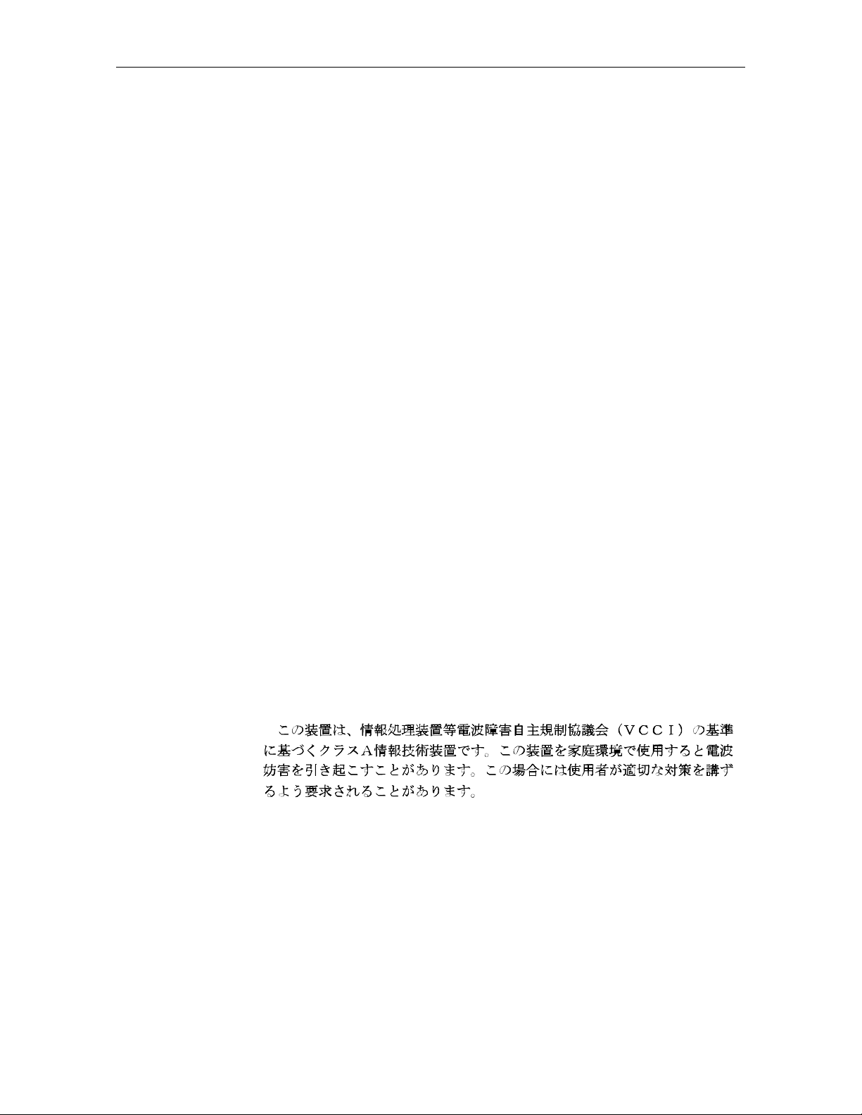
Scale Identi fication Lab el
NCR CORPORATION
Model 7875-2000
Max 13.995 kg Min 0.1 Kg ID
e = d = 0.005 kg Approval
Lim 19.990 kg +10 C /+40 C Serial No
13.995 Kilogram (kg) Label
NCR CORPORATION
Model 7875-2000
Max 9.995 kg Min 0.1 Kg ID
e = d = 0.005 kg Approval
Lim 19.990 kg +10 C /+40 C Serial No
NCR CORPORATION
Model 7875-2000
Max 30.00 Ib Min 0.2 lb ID
e = d = 0.01 lb Nmax3000 Approval
Lim 44.00 lb +10 C /+40 C Serial No
NCR CORPORATION
Model 7875-2000
Max 30.00 Ib Min 0.2 lb ID
e = d = 0.01 lb Nmax3000 Approval
Lim 44.00 lb +10 C /+40 C Serial No
Note: e = scale interval; d = scale division;
Max 30.00 lb = maximum weight permitted on scale
Min 0.2 lb = minimum weight that should be measured on scale
Nmax3000 = maximum scale divisions
9.995 Kilogram (kg) Label
Pound (lb) Label
Removing Label causes
VOID Indication
16884
Page 17
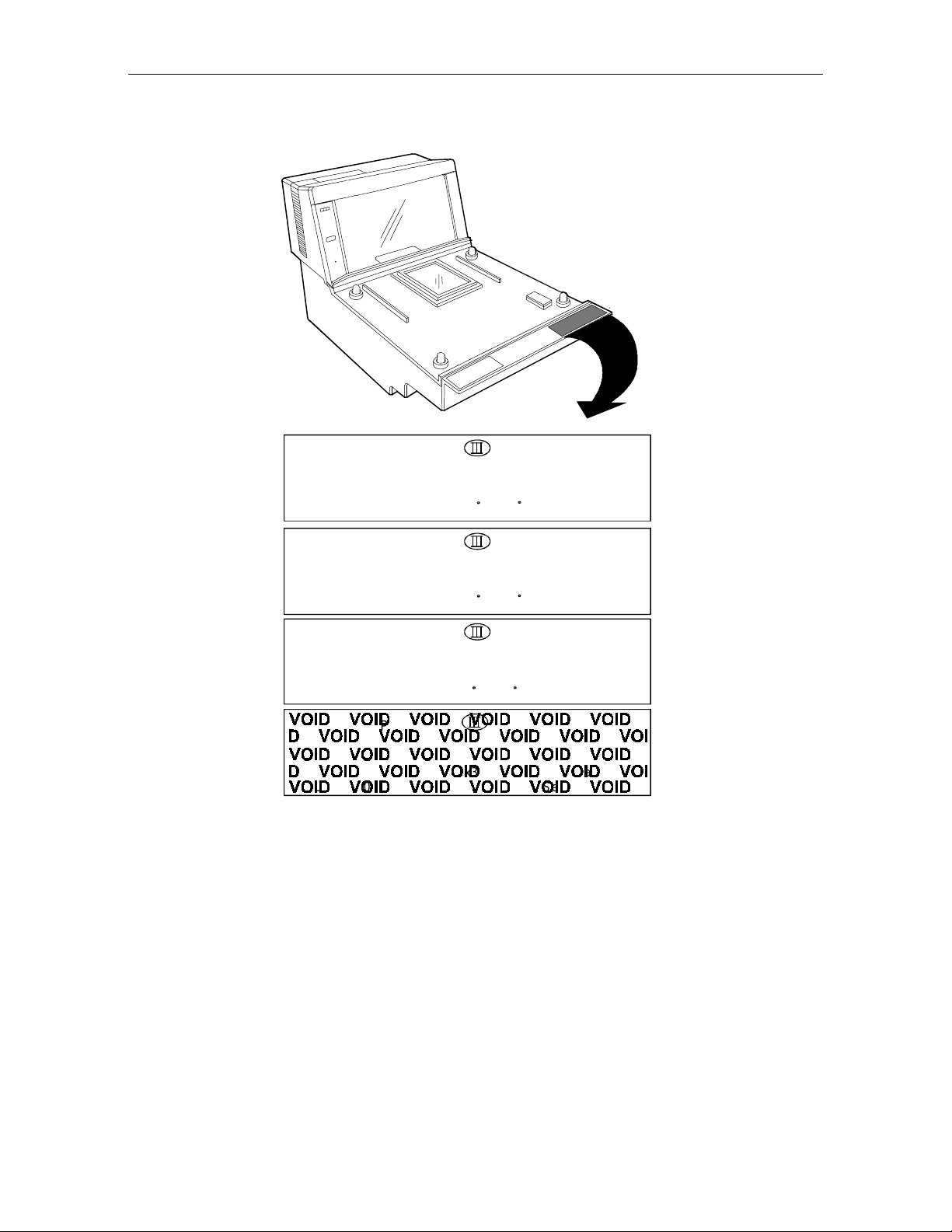
Laser Safety
The NCR 7870 Scanner is not intended for long-term viewing of the
direct laser lig ht. However, the unit is sa fe if us e d as it was in t e n ded.
Laser Saf et y Label
Class IIa Laser Product. Avoid Long-Term Viewing of Direct Laser Light.
Appareil á laser de classe IIa Dviter toute exposition
prolongée de la vue á la lumiére laser directe.
Clase IIa Producto Laser. Traté de no ver directamente él Rayo
Laser por mucho tiempó.
(IEC CLASS 1 LASER PRODUCT)
User's Gui de xv
R0130
Page 18

xvi User's Guide
Country Language Specific IEC Class 1 Laser Labels
CLASS 1 LASER
PRODUCT (IEC 825)
APPAREIL A LASER
LASER KLASS 1
Zeitbasis 1000 s
DE CLASS 1
PRODUCTO LASER
CLASE 1
LUOKAN 1
LASERELAITE
KLASS 1
LASER APPARAT
R0130B
Page 19

Laser M odule Label
User's Guide xvii
Laser Power
This laser module
does not comply
with 21CFR1040.
USE ONLY AS A
COMPONENT.
R0132A
The NCR 7870 Scanner meets the following laser power requirements.
• Class IIa CDRH (Center for Devices and Radiological Health)
• Class 1 EN60-825 (Europäische Norm)
• Class 1 IEC 825-1 1993 (International Electrotechnical
Commission)
Page 20

xviii User's Guide
Following is the radiant energ y of the las er light as applied to each of
the specified requirements.
Maximum Average Radian t Power (CDRH Cal cu lation)
Accessible Emi ssion Lim it (CDRH Calculation)
Maximum Radiant Power (EN60825-1 / IEC 825-1 Calculation)
Accessible Emission Limit (EN60825-1 / IEC 825-1 Calcul ation)
0.87 microwatts
3.9 microwatts
0.45 milliwatts
0.59 milliwatts
Caution: Use of controls or adjustments or performance of procedures
other than specified herein may result in hazardous radiation
exposure.
Page 21
Chapter 1: Introduction
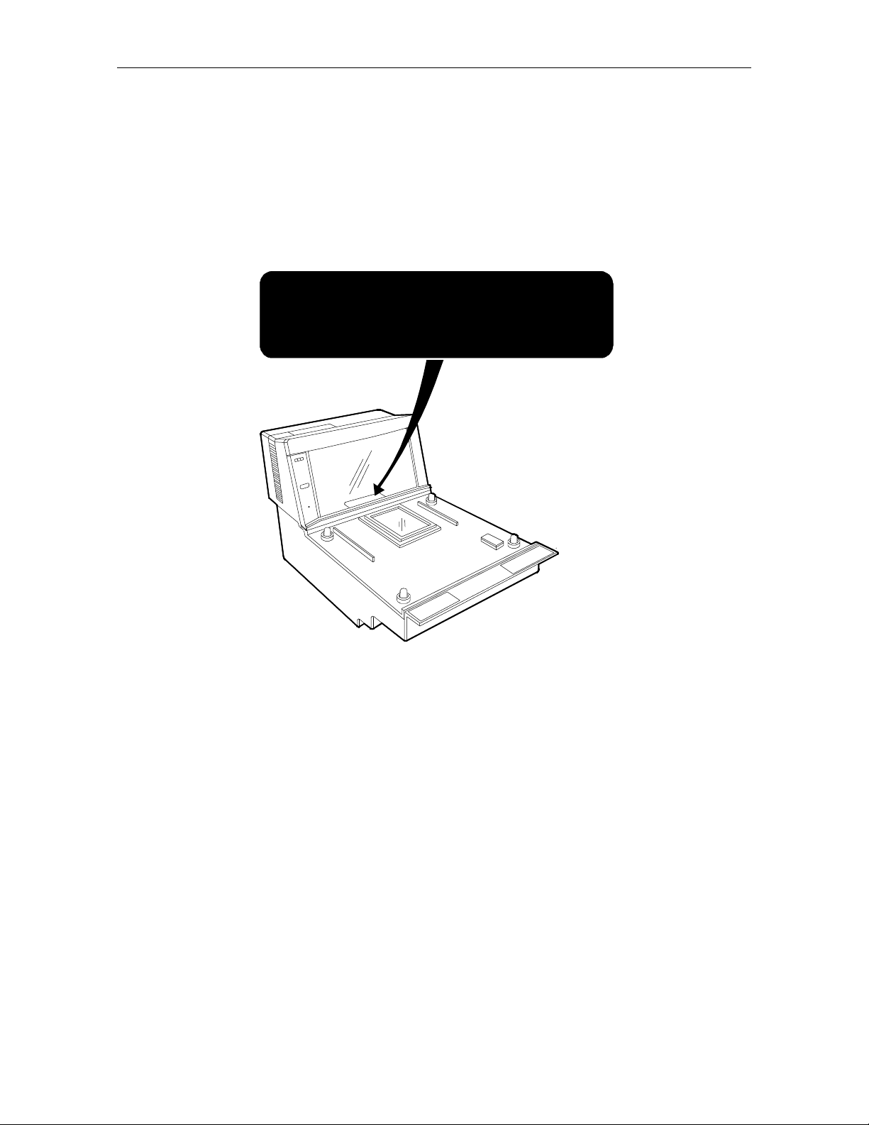
This chapter describes the models, features, and kits available for the
7870 line of scanner/scales. To familiarize you with the 7870, there is a
general overview on the unit, the models, and major components.
NCR 7870
Scanner/Scale
Power Supply
Power Cable
Power Cord
R0122
Page 22

1-2 Chapter 1: Introduction
About the NCR 7870 Scanner/Scale
The NCR 7870 is used in high-performance scanning applications in
food distribution, mass merchandise, warehouse clubs, and large drug
store chains. It is a bi-optic scanner/scale that combines the
characteristics of a slot (horizontal) scanner and a side (vertical)
scanner into a single cabinet.
Bi-optical sca n n in g crea t es a larger, four-side d scan zone which allows
the 7870 to read bar codes faster and with less orientation effort from
the checker. Scan line speeds of 2,400 lines per second permit
continuous item speeds of 2 meters per second. A good checker
operates in the range of 0.8 to 1.0 meters per second.
Models
The PACESETTER
Standard Decode feature, analyses and corrects information from
defective labels. PACESETTER
you can iden t ify p r od u cts and man ufacturers wit h poo r label q uality.
The scale will we ight items less fiv e po un ds (2 . 2 7 kg ) in 0.9 seconds.
The weight plate is offset toward the checker, allowing the checker to
do what is natu ra l wh en lift in g heavy object s – pull the we ight closer to
the body. This less e ns ope ra to r lo wer ba ck strain.
The overall resu lt o f these and many other design qua lit ies is an
ergonomic scanner/scale with a very high first-pass read rate.
The NCR 7870 is av a ilable in fiv e mode ls:
• 7870 - 1000 - 9090 – scanner only, standard length
• 7870 - 2000 – 9090 - scanner and scale, standard length
• 7870 - 3000 – 9090 - compact scanner only
• 7870 - 4000 – 9090 - compact scanner/scale (third party scale,
Plus
technology, available as an upgrade over the
Plus
also keeps track of bad labels so
European market)
• 7870 - 4500 – 9090 - compact scanner/scale (NCR scale)
Page 23

Reading the Product Number
Class 7870
Major Model:
10 = Scanner (Standard Size)
20 = Scanner/Scale (Standard Size)
30 = Scanner (Compact)
40 = Scanner/Scale (Mid-Size, European Scale)
45 = Scanner/Scale (Mid-Size)
Sub-Model: none
Power: 90 = No Characteristics
Language: 90 = No Characteristics
Common Fe atures
Chapter 1: Introduction 1-3
7870 XX00 90 90
14943
• Standard Decode or PACESETTER
Plus
and Standard Decode
• Interfaces for popular host terminals
• Large select io n o f p o we r cords t o meet cus t om a n d reg io n a l
needs while providing fle x ible co n figuration s wit h t h e
universal power supply
• Data cables ordered separate or as part of a kit
• For Scanner/Scale models -- NCR 7825 Remote Display
(standard for curren t mode ls ), In t egrated Display, or No Display
• Print or on-lin e d ocumentation
• Choice of Stainless Steel Top Plate equipped with either
Sapphire or Diamond-Coated Glass Scan Window
• Custom labels fo r t h e scann e r and scale t o mee t local
requireme n ts for las e r safe ty a n d/or weights and measur es
Page 24

1-4 Chapter 1: Introduction
7870-1000-9090
7870-2000-9090
7870-3000-9090
This is the st anda rd bi-o p t ic scanner only model. It is full-sized,
designed to fit in a 20+ inch (51+ cm) wide checkstand. It can be
configured with a variety of top plates and glass options. The 78701000 will fit into the counter hole for the NCR 7820.
This is the st anda rd bi-o p t ic scanner/scale m od el. It is ide n t ical t o the
7870-1000 with the addition of a scale unit. The 7870-2000 can be
ordered with the post-mounted NCR 7825 Remote Display (standard),
an integrated display, or no display. The 7870-2000 will fit into the
counter hole for the NCR 7820.
This is the com p a ct, bi-optic, scanner only mode l. With the sca le be d
removed, the length is reduced to 34.3 cm (13.5 in.) to fit in European
checkstands where space is tight and the checker is often seated.
7870-4000-9090
7870-4500-9090
This is the subco m pact scann e r/s ca le mod e l. With a lengt h o f 43 cm
(17 in.), the 7870-4000 has a footprint between that of the full-sized
1000/2000 models and the compact 3000 model.
The 4000 model uses a price-computing scale to meet European
requirements. This scale uses info rm a tio n obtained from the host
terminal and the measured weig h t to ca lcu la te the price in t e rn ally. The
price computing function makes the 4000 model different from all
other 7870 model scales which measure item weight and transmit the
data to the host term inal for price calculatio n .
The 4500 model is identical to the 4000 model except the scale has no
internal p rice -co m puting function a n d is manufactured by NCR .
Page 25

Chapter 2: Features, Functions, and Kits
This chapter describes the features, functions, and kits. Specification
and performance data on the 7870 unit and its major components is
also provided.
General Features and Functions
Bar Code Recognition
The 7870 can recognize and read a number of bar codes including:
• UPC-A • Code 39 (Code 3 of 9)
• UPC-E • Code 128
• UPC-D (limited s e t ) • Interleaved 2 of 5
• EAN-8/13 • Add-On Codes
• JAN-8/13
It is possible that in some situations, the 7870 may be able to read more
types of bar codes than the host terminal’s application program. In
such a case, either the application program must be upgraded to read
these bar codes or the 7870 must be told, using the Programming Tags
(BST0-2121-74), to ignore the particular bar code type.
Page 26

2-2 Chapter 2: Features, Functions, and Kits
Bi-Opti c Sca nni ng
The NCR 7870 combines horizontal and vertical scan patterns. Having
two active scan windows allows the checker to bring a product into the
scan zone without having to orient it to a single scan window. Portions
of the bar code are read by each scanner, assembled into a complete
code by the digital board and sent to the host terminal.
Decode Features
Standard Decode and PACESETTER
label decoding. Standard Decode is the standard feature and
PACESETTER
Plus
upgrade includes the Standard Decode.
PACESETTER
Bar code labels in a ret ail env iron ment are occasiona lly un rea d able .
Labels can be overprinted, underprinted, or truncated. Others may
have missing margins or be placed around corners. PACESETTER
determine s wh a t is wro ng wit h a la be l, compensat es and fix es the d ata,
and transfers the information to the host terminal. Voice messages can
be used to describe what is wrong with a label.
There are three modes of operation in PACESETTER
• Mode 1 – Inqui r y Mode
• Mode 2 – Real-T ime Mode
• Mode 3 – Oper ati ons M ode
Mode 1 – Inquiry Mode
Inquiry mod e kee ps a t a lly cou nt of label readabilit y . Labels are
judged as:
Plus
is the upgrade. Please note that the PACESETTER
Plus
Plus
are available for bar code
Plus
Plus
.
Good reads No reads (incomplete labels)
Good reads with overprinted bars Missing margins
Good reads with underprinted bars
Page 27

Displays
Chapter 2: Features, Functi ons, and Kits 2-3
In Mode 1 the t a lly counts are disp layed on the int eg ra t e d dis play or
the NCR 7825 remote display. The percentage of each error type to the
good reads t a lly is als o d isp la yed. All the tally counts can be reset to
zero.
Mode 2 – Real-Time Mode
In Mode 2 the scanner is off-line and the scale is disabled. The scanner
reads bar codes and in d ica te s la bel re a da bilit y , whethe r labels a r e
missing bars, overprinted, underprinted, missing margins, or are “no
read.”
Mode 3 – Operations Mode
Mode 3 is the norm a l ope ra t ing mode . While in t h is mod e, the scanner
can be programm e d to add traile r in fo rm a tio n a bou t label re a da bilit y
to the UPC/EAN data. The host terminal must be capable of receiving
the trailer and configured appropriately.
A display separate from the host terminal is useful and sometimes
required for use with NCR 7870 Scanner/Scales -- the 2000, 4000, and
4500. These models are available with a remote post-mounted display,
an integr at e d d isp la y, or no display .
NCR 7825 Remote Di sp l a y
The post-mounted NCR 7825 is the standard display and is available as
a user-inst a lla ble kit to upgrade older u n its in th e field. Early v ersio n s
of the NCR 7825 Remote Display are mounted on a post that attaches
to the checkstand. The current NCR 7825 is a compact design available
with a single or dual display, one for the customer and one for the
checker. The following illustrat ion shows the curren t mod el wit h du al
displays a n d the earlie r m o de l.
Page 28
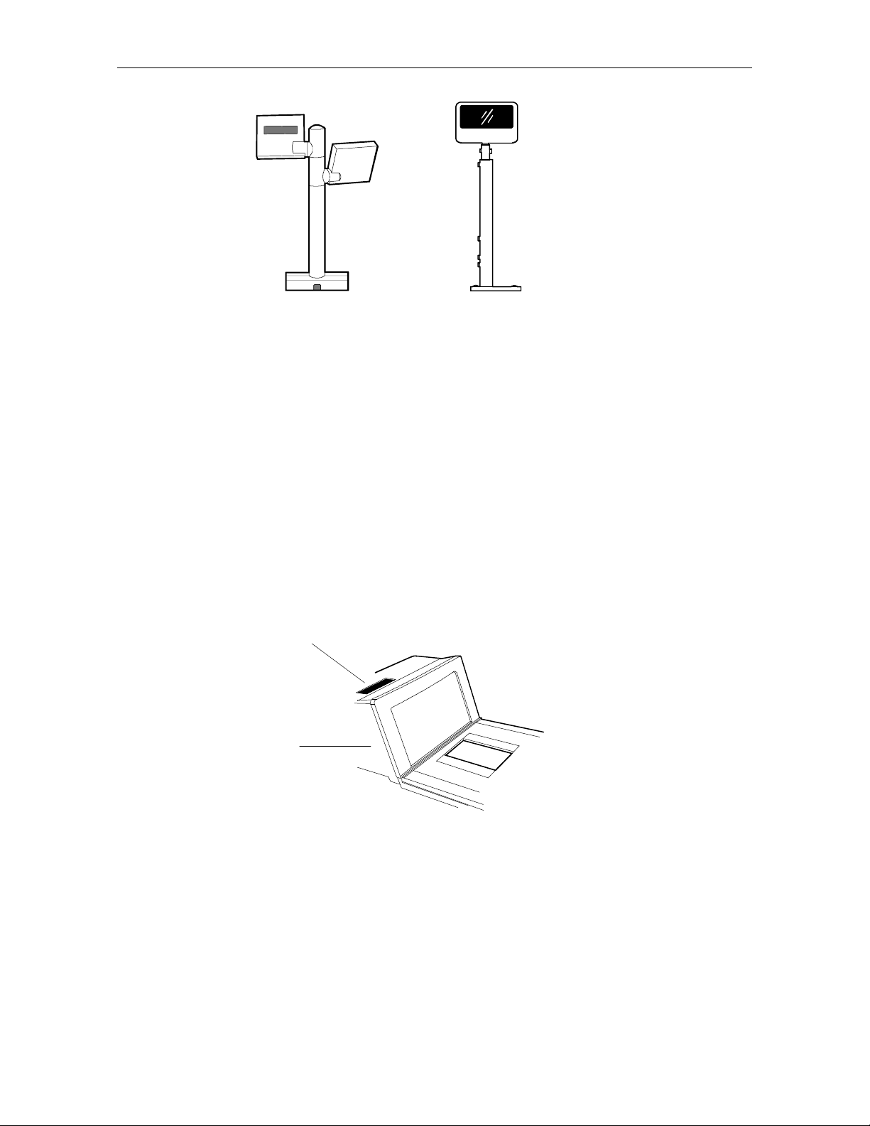
2-4 Chapter 2: Features, Functions, and Kits
NCR 7825 Remote
Compact Display
NCR 7825 Remote
Post Display
16345
Depending on the checkstand construction, a keyboard may be
mounte d above the 7 870, wh ich will o bs t ru ct the v ie w of the int egrated
display. In this case, it may be advantageous to install an NCR 7825
Post Mounted Display, which can be used with or without an
integra t e d display.
Integrated Display
The integrated displa y is an inset, LCD locate d o n th e top su rfa ce of t h e
tower. Depending on the checkstand design, the integrated design
may or may not be appropriate.
Integrated Display
Tower
16819
Page 29

Interf ace Ty pe s
Laser Scan n er
Chapter 2: Features, Functi ons, and Kits 2-5
No Display
If the 7870 is ordered with no display, the scale information is usually
displayed on the host terminal display. Please note, the host terminal
must be approved to perform a live/gross scale weight. This
arrangement is not available in all host terminals and some Weight and
Measures au thorit ies do not permit this arrang ement.
The NCR 7870 communicates with the host terminal through various
types of interfaces. The 7870 Scanner always uses one interface cable.
However, some host terminals require dual cables for and NCR 7870
Scanner/Scale. See the
Preparation for available interface cables.
The 7870 operates with the performance of two scanners yet the bioptic scan pattern is created by a single laser and spinner motor. A 24 line convergent scan pattern (1 2 lines per scan window) is gen e ra ted by
the laser diode. A 3-Phase, DC, brushless motor spins a tetrahedral
mirror at 6000 RPMs. The laser beam is reflected onto the stationary
mirrors in the Optics Assembly and then out the Scan Windows. The
Spinner Motor provides a scan speed of 2400 scan lines (100 scan
frames) per second. This enables the 7870 to read at a continuous item
speed of 2.0 meters per second. An experienced checker scans at a rate
of 0.8 to 1.0 meters per second, so the 7870 is able to keep up with high
volumes and fast checkers.
Interface Cables
section in Chapter 3: Site
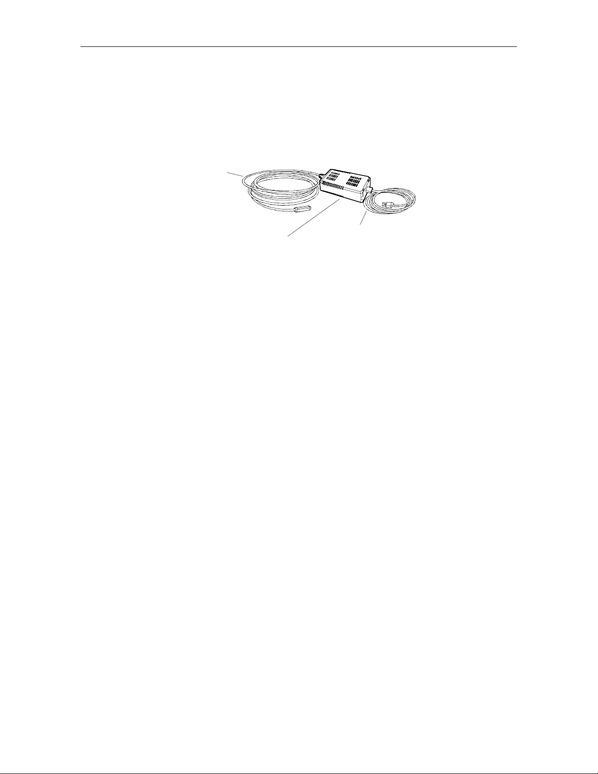
Power Supply
A univers al, switching P o we r Supp ly is us e d to prov id e DC volt a g e. It
has a replaceable, 3 m (10 foot) cord for connection to the power outlet
or source . A low volta ge power cable conn e ct s the Power Supp ly to
the unit. The Power Supply can be fixed to the unit’s chassis on or
located on the floor or checkstand in the NCR 7870-1000 and 2000. For
other mod e ls, th e Po wer Supp ly must be insta lle d in th e che ckstand.
Page 30
2-6 Chapter 2: Features, Functions, and Kits
An outboard power supply permits the 7870 to operate without
checkst a n d ve n t ilat io n . The Power S up p ly a cce p t s in pu t lin e vo lta ges
from 90 to 260 VAC at a frequency range of 47 to 63 Hz.
For a list of Power Cables and Cords, see the
Sizes
section in Chapter 3: Site Prepar a tio n.
Power Cable
(To AC)
Outboard Power Supply
Programming the 7870
The NCR 7870 is featurized to fit a customer’s needs by using
programm ing tags which alt e r the un it ’s operating parameters.
Following are some of the more common parameters which may be
adjusted:
• Communications Protocol • Code 39
Power Cord (To Unit)
Cables Lengths and Hole
16822
• Good Read Tone • Code 128
• Not-On-File Tone Volume • RS-232
• Timers • Interleaved 2 of 5
• UPC/EAN • PACESETTER
Plus
• Add-On Code • Label Identifiers
Page 31

Scale Cert if icat i on s
Scale certifications are available for these markets:
Market 9.95 kg 13.995 kg 30 lb.
Chapter 2: Features, Functi ons, and Kits 2-7
Argentina
Australia
Brazil
California
Canada
Czech Republic
Europe
Hong Kong
Indonesia
International
Mexico
New Zealand
People’s Republic of China
Russia Fede r a tion
United Kingdom
•
••
•
•
•••
•
•
••
•
•
•
••
•
•
•
U.S.
Venezuela
Vietnam
•
•
•
Page 32

2-8 Chapter 2: Features, Functions, and Kits
Scan Zone
The scan lines are dispersed in a forward and backward direction from
both windows. This allows the scanner to read a) on four sides, b)
from left-to-right or right-to-left, and c) inverted labels. If the scan
zone is thought of as a cube resting on the horizontal scan window, the
scanner is able to read the le ad ing, t ra ilin g, bottom, and fa r surfa ce s.
Another way of describing the scan zone is – if the checker can’t see the
bar code label, then the scanner can. The scan zone extends to 20.3 cm
(8 in.) high off the horizontal window. Bi-optical scanning makes the
scan zone large enough to allow a labe l to be read off o f a tall sou p ca n
even when upside-down
Scanner Power Requirements
The laser diode occupies little space, draws low current, and produces
little heat. The light produced by the scanners in current models has
been shifted toward the edge of the visual spectrum so it is not possible
to see the scan pattern in normal lighting. When active, the laser uses
22 watts. A soft power down feature allows major portions of the 7870
to shut down when no motion is detected. While in sleep mode, the
scanner’s power requirements drop to 10 watts, a 65% reduction. A
more valuable advantage of the soft power down feature is the run
time reduct ion o f critical com ponents wh ich t ranslates directly into
extending the life of the scanner. The scanner automatically powers up
after detecting motion in approximately two seconds.
Soft Power Down
During periods of inactivity, components of the scanner and scale shut
down to conserve power, reduce wear, and extend product life. A
motion sensor detects activity and signals the unit to power up from
sleep mode. The power up takes less than two seconds.
Page 33

Top Plates and Scan Wi ndows
Top Plates
A Top Plate provides a snag-free place to scan items and protects the
internal components from con t a m inat ion and liquid sp ills . It has an
inset Lift Ta b (o lde r un its may have two) which permit the Top Plate to
be quickly removed or replaced with no tools. The scan window inset
in the Top Plate is either diamond-coated (replaceable) or sapphire
glass (permanent). When a unit has a scale, the Top Plate becomes a
part of the scale system – the scale must be recalibrated when the Top
Plate or any of its components, such as the scan window, are replaced.
The current line of 7870 Scanners and Scanner/Scales have been
upgraded to come with the Stainless Steel Top Plate as a standard
feature. Older 7870 units may have the painted steel Top Plate which
is no longe r availa ble .
Chapter 2: Features, Functi ons, and Kits 2-9
Slot (Horizontal) Scan
Window
Top Plate
Lift Tab
Slot Scanner Window
The (horizon t al) scan window is mounted in the Top Plate . Th e
window (if diamond-coated) is replaced by removing the Top Plate,
snapping out the old window, and snapping the new window in place.
The slot scanner window is available as diamond-coated glass or
sapphire glass. Diamond-coated glass was formerly known as
“scratch-resistant” glass. Sapphire glass is the upgrade and was
formerly known as “scratch-proof” glass. Other glass options such as
“hardened” and “armor” glass have been discontinued.
Page 34

2-10 Chapter 2: Features, Functi ons, and Kits
Side Scanner Window
The NCR 7870 vertical scan window is mounted in a tower that rises
above the checkstand surface. The scan window can be removed from
the unit for cleaning. The upper console containing the scan window is
designed to withstand occasional impacts.
Side (Vertical) Scan Window
Slot (Horizontal) Scan Window
16821
Page 35

Scale Features and Functions
The scale is used in the 2000, 4000, and 4500 models. It can be
manufactured by NCR or by a vendor for a specialized market such as
the price-computing scale in the 4500 model to meet European
standards.
Scale Funct i on s and Fe atures
Load Cell
The NCR 7870 uses a sing le loa d ce ll rat h e r than four, which is more
typical, t o increa se reliability. Th e sca le has a se tt lin g t ime of 0.9
seconds fo r ite ms weighing less than 2.3 kg (5 lbs.) It is sealed to avoid
damage from spills aroun d the unit. There are three basic ty pes of load
cells:
• For weigh ing in pounds. Capacity: 30 lbs.
• For weigh ing in k ilo g r ams. Capacity: 9. 9 9 5 kg
Chapter 2: Features, Functi ons, and Kits 2-11
• For weigh ing in k ilo g r ams. Capacity: 1 3. 9 95 kg
Reset / Scale Zero
A front-mounted Scale Reset button is located on the front bezel, to the
left of the ve rtica l scan window. This flush m embrane switch will res et
the scale due to fluctuation from extreme temperature drift, impact, or
scale tare up to:
1. 0.3 kg (0.6 lbs.) relative to the zero established during the most
recent power-on sequence
or
2. 0.6 kg (1.2 lbs.) relative to the calibrat io n ze ro , wh ich ev e r is less.
The scale res et function is comple t e d in less than a second.
Auto-Zero
Scale electronics automatically tracks out stable shifts due to
temperature changes and compensates in 3 g (0.006 lb.) increments up
to a maximum of 0.3 kg (0.6 lbs.).
Page 36

2-12 Chapter 2: Features, Functi ons, and Kits
Kits
Kit Name Kit Type A v a ilable for
Enhanced Scratch Resistant
Window
7870-K002-V001
Upper Windows (Qty: 5)
7870-K003-V001
Stainless Steel Top Plate
7870-K005-V002
Scale Shell Model
7870-K007-V001
Digital Board Upgrade (Board,
Firmware)
7870-K100-V001
Requirements: For units with S/Ns below 50-28901727, adds Speech
and Coupon Add-On Code.
Hardware 7870-1000
7870-2000
Hardware All
Hardware 7870-1000
7870-2000
Hardware N/A
Hardware,
Firmware
All
PACESETTER
(OCIA/IBM)
7870-K401-V001, -V002
Requirements: V001 supports
units with S/Ns 50-28901727
or lower. V002 supports units
with S/Ns 50-00000000 and
higher.
Plus
Upgrade
Firmware All
Page 37

Chapter 2: Features, Functi ons, and Kits 2-13
Kit Name Kit Type A v a ilable for
PACESETTER
Plus
Upgrade
Firmware All
(RS-232/Datachecker)
7870-K402-V003, –V002, -V003
Requirements: V001 supports units with S/Ns 50-28901727 or lower.
V002 supports units with S/Ns 50-00000000 and higher. V003 has a
PACESETTER
Multi-Sy m bo l Upgrade
Plus
trailer fix.
Firmware All
7870-K404-V002
Requirements: For units with S/Ns 50-28901727 and higher. If
upgrading a unit with a lower S/N, install kit 7870-K100.
13.995 kg Upgrade
7870-K440-V001
Firmware,
Hardware
7870-2000
Requirements: For upgrade from 9.995 kg to 13.995 kg on units with
S/Ns 50-28901727 and higher. To upgrade a unit with a lower S/N,
install kit 7870-K100.
OCIA/IBM Inter face – Single
Cable
Hardware,
Firmware
All
7870-K450-V001, -V002
Requirements: V001 supports units with S/Ns 50-28901727 or lower.
V002 supports units with S/Ns 50-00000000 and higher.
OCIA/Interface – Dual Cable
7870-K451-V001, -V002
Hardware,
Firmware
7870-2000
Requirements: V001 supports units with S/Ns 50-28901727 or lower.
V002 supports units with S/Ns 50-00000000 and higher.
Page 38

2-14 Chapter 2: Features, Functi ons, and Kits
Kit Name Kit Type A v a ilable for
RS-232 Interface (Board,
Firmware)
Hardware,
Firmware
All
7870-K452-V003
Requirements: V001 supports units with S/Ns 50-28901727 or lower.
V002 supports units with S/Ns 50-00000000 and higher. V003
enhances the old digital board firmware.
Datachecker, 2170, ICL MDL,
ICL 9518/9535, SASI Interface
Hardware,
Firmware
All
7870-K455-V001, -V002, -V003
Requirements: Kit is for interfacing with these host terminals: NCR
2170 (RS-232, Weightronix Emulation), Avery Emulation (RS-232),
Datachecker (RS-422), ICL MDL, ICL 9518, ICL 9535 (ICL Team POS
5000), SASI.
V001 supports only ICL T2001, V002 supports units with S/Ns 50-
28901727 or lower. V003 supports units with S/Ns 50-00000000 and
higher.
Non NCR OCIA
7870-K457-V002
Hardware,
Firmware
All
Requirements: V001 supports units with S/Ns 50-28901727 or lower.
V002 supports units with S/Ns 50-00000000 and higher.
Casio and TEC Scale Interface
7870-K458-V003
Hardware,
Firmware
7870-2000
Requirements: V001 supports units with S/Ns 50-28901727 or lower.
V002 supports units with S/Ns 50-00000000 and higher. V003
supports the same as V002 plus TEC.
Page 39

Chapter 2: Features, Functi ons, and Kits 2-15
Kit Name Kit Type A v a ilable for
IBM 4682/4693/4694 Standard
Interface and IBM 4682-4B Full
Hardware,
Firmware
All
ASCII Inte r face
7870-K459-V002
Requirements: V001 supports units with S/Ns 50-28901727 or lower.
V002 supports units with S/Ns 50-00000000 and higher.
Datachecker 2000 Interface
Hardware All
7870-K463-V001
Requirements: 7870 must be configured for Single-Cable, OCIA.
Dual Cable RS-232 Interface for
I/F 1
Hardware,
Firmware
7870-2000
7870-K465-V001
Requirements: 7870 must be configured for OCIA or IBM
communications. Avery Emulation (RS-232), Weightronix Emulation
(RS-232) for scanners with an I/F 1 Interface Board.
Australia with I/F 1 Interface
to 2126 Dual Cable 13.995 kg
Hardware,
Firmware
7870-2000,
kg units only
(Coles)
7870-K466-V001
Requirements: For upgrading units with a) S/Ns 50-28901727 and
higher and b) I/F 1 Interface Board from 9.995 kg to 13.995 kg. To
upgrade units with lower S/Ns, kit 7870-K100 must also be installed.
If the unit has an I/F 2 Interface Board, kit 7870-K450 must also be
installed.
Integra t e d Displa y
Hardware All
7870-K480-V001
Page 40

2-16 Chapter 2: Features, Functi ons, and Kits
Kit Name Kit Type A v a ilable for
Top Plate with Scratch-Proof
Window (Standard size)
Hardware 7870-1000
7870-2000
7870-K601-V001
Top Plate with Scratch-Proof
Hardware 7870-3000
Window (Compact)
7870-K605-V001
WalMart/Argentina Upgrade
7870-K846-V001
Hardware,
Firmware
7870-2000
Requirements: To upgrade a 9.995 kg scanner/scale to Argentina
requirements, unit must have a) S/N 50-28901727 or higher and b) an
NCR 7825 Remote Display.
Coupon Add-On Code
Firmware All
Upgrade
7870-K850-V001
Requirements: For units with S/Ns between 50-28901727 and 50-
31148616. For units with S/Ns 50-2891727, use kit 7870-K100. For
units with S/Ns 50-31148616 and larger, no kit is needed – enabl e
feature through programming options.
Checkpoint Scanner Bezel
7870-K896-V001
Hardware 7870-1000
7870-3000
Requirements: A Checkpoint representative must make the final
connection from the 7870 to the Checkpoint equipment after kit
installation.
Page 41

Chapter 2: Features, Functi ons, and Kits 2-17
Kit Name Kit Type A v a ilable for
Checkpoint Scanner/Scale
Hardware
Bezel
7870-K898-V002, -V003
Requirements: Kit is mandatory for upgrading to Checkpoint on units
with S/N 50-32573274 or lower. For units with higher S/Ns, may use
this kit or kit 7870-K899-V001. V002 is for use in U.S. and Mexico
only. A Checkpoint representative must make the final connection
from the 7870 to the Checkpoint equipment after kit installation.
Checkpoint Scanner/Scale
Hardware
Bezel
7870-K899-V001
Requirements: For units with a S/N 50-32573274 and higher. For
units with a lower S/N, install kit 7870-KK898-V003. A Checkpoint
representative must make the final connection from the 7870 to the
Checkpoint equipment after kit installation.
Page 42

2-18 Chapter 2: Features, Functi ons, and Kits
Page 43

Chapter 3: Site Preparation
For the NCR 7870 to operate efficiently and safely, the selected
installation site must meet certain requirements. Ensuring that these
conditions are met and maintained will protect the 7870 from
unnecessary wear and pot e n t ia l dam a g e as we ll as e as in g in st a lla t ion.
This chapte r cov e rs
• Getting Started
• About Site Preparation
• Custom e r Responsibilities
• Environmental Requirements
• Checkstand Power and Wiring Considerations
• Checkstand Considerations
• Cable Lengths and Hole Sizes
• 7870 Dimensions
Page 44

3-2 Chapter 3: Site Preparation
Getting Started
The first step to preparing the selected site is to read the following two
secti o ns – About Sit e Prepar ation and C u sto mer Resp onsibilities.
These sections provide imp ort ant in fo rm a t ion abou t NCR’s and your
responsibilities to keep the NCR 7870 safe and in good working order.
The next step is to ev a luat e the ch ose n s it e for its s uitability. As a
minimum, these conditions need to be accessed:
• Is the environment controlled within the 7870’s operational range
• Will other ele ctr onics be pla ced in ch eckstand which co u ld
• Will the power circuit to supply the 7870 be
for temperature, temperature change, relative humidity, barometric
pressure , ambie n t light, acoust ic n oise, vibration, and shock?
necessitate use of forced air to regulate the temperature?
• dedicated to NCR equipment only and so labeled,
• equipped with an isolated, insulated ground,
• providing the re quire d in pu t to th e Power Supp ly,
• equipped with a recessed, 15-amp circuit breaker convenient to
the checker, and
• equipped with protection against voltage transients?
• Is the checkstand
• able to securely support the weight of the 7870 and
• properly ventilated?
• Has the plan for the checkstand design considered
• use of a diverter or an adjustable plate,
• clearance needed for service and customer viewing of display,
• location and size of hole for cable rout in g, and
• providing enough slack in cables so 7870 may be removed from
checkstand for service without disconnection?
Page 45

Chapter 3: Site Preparation 3-3
The following sections contain the NCR 7870’s requirements. These
specificatio n s will a llo w y o u t o evalu a t e the s ite for in s t a lla tio n .
The l ast step is t o i mpl ement th e necess ary changes b efor e beginn i ng
the installa t ion process describe d in Chapter 4: Installation .
Page 46

3-4 Chapter 3: Site Preparation
About Site Preparation
This chapter co n t ains the in forma t ion necessary for the pre p a ration o f a
site conforming to NCR specifications. It is very important that the site
complies wit h th e requ ire m ent s in this do cu ment because, on ce the
equipment has been installed, deficiencies in site preparation or the
problems ca us e d by the se deficiencies a re mu ch mo re difficu lt t o d et e ct
or correct. Further, failure to comply with these requirements or to
take proper steps to protect equipment against risks identified in this
document may cause serious damage to the equipment and to the
customer’s business.
In addition to the need to comply with the requirements specified,
electrical wiring and mechanical systems must also comply with all
relevant cod e s, la ws, and regulation s.
It is important that the site be prepared by a customer or a customer
agent who is fully conversant with the special requirements of
electronic eq u ipment. The respons ibilit y o f e n su rin g t h a t the s ite is
prepared in compliance with this document remains with the
customer.
For informa t ion an d guid a n ce pu rposes only, a lis t is prov id ed , in
general terms, of these matters for which the customer is responsible.
This list is not in t ende d to be comprehensive , a n d in no way mod ifies,
alters, or limit s the responsibilit y of the custom e r for all asp e cts o f
adequate site preparation.
NCR staff is available to answer questions relating to the contents of
this docum e n t, bu t ex ce p t whe re:
a) the customer has been notified that a full or partial consultancy
service is availa ble and/or that NCR is willin g to undertake a
prelimina ry or final site surve y an d
b) the customer shall have entered into a formal contract with
NCR for provis ion of the same.
Page 47

Chapter 3: Site Preparation 3-5
No comment, suggestion, or advice offered or not offered about
preparation of the site nor any inspection of the site whether before or
after preparation is to be taken as approval of the location of the site
and equipment or of its prepa ra t ion , a n d NCR is n o t liable in re spect of
any comment, suggestion, or advice given by its staff or in respect of
any failure to give advice.
Finally , only the cust ome r can kn o w t h e full e x t ent o f dam ag e which
may be caused to his business by reason of failure of the equipment
which is to be in st alle d . Fo r this re a son, it is the cus tom er ’s
respons ibility to ascerta in t h e ex t ent o f any su ch possible damag e to h is
existin g or plan ned business, and to effect full insurance in respect of it.
Page 48

3-6 Chapter 3: Site Preparation
Customer Responsibilities
The customer must do or provide the following.
• When required by NCR, provide the NCR Customer Services
Representative with appropriate drawings that indicate
• location of equipment,
• site wiring (power and signal, paths, and lengths),
• Location of other equipment capable of generating large
amounts of electrical noise, electromagnetic interference,
heat, and so on.
• Provide floor coverings and environmental systems that
prevent static electricity build-up and discharge.
• Provide an d install necessary power dist ribu t ion box e s,
conduits, grounds, lightening arrestors, and associated
hardware.
• Make sure clear space and environmental requirements of the
unit are met.
• Make all buildin g alterations nece ssary to meet wiring a n d
other site requirements.
• Make sure all applicable codes , regulations, and laws
(including , but not limited t o, e le ct rica l, building , safety, and
health) are met.
• Provide and install all co mmunicatio n ca ble s, wa ll jacks, spe cial
connectors, and associated hardware.
• Provide and install auxiliary power or other equipm ent as
required.
Page 49

Environmental Requirements
Operating Range
Condition Range
Temperature
Chapter 3: Site Preparation 3-7
10° C – 40° C(50° F – 104° F)
Temperature Change
Relative Humidity 5% to 95%, Non-Condensing
Barometric Pressure 79.5 x 10³ Pa to 105 x 103 Pa
Ambient Light 200 Foot-candles max (2152 Lux)
Acoustica l No is e 55 dBa or less
Vibration and Shock 1 to 10 Hz with a double amplitude of
10° C per hour (18° F per hour)
on both scanner windows
0.127 cm (0.05 in.)
10 to 300 Hz with a maximum of 0.25 gee
Extreme Operating Range
Condition Range
Temperature
Temperature Change
-15° C to 45° C (5° F to 113° F)
one hour max
20° C per hour (36° F per hour)
Relative Humidity 5% to 95%, Non-Condensing
Page 50

3-8 Chapter 3: Site Preparation
Storage Range
Condition Range
Temperature
-15° C to 50° C(5° F to 120° F)
Temperature Change
20° C per hour (36° F per hour)
Relative Humidity 5% to 95%, Non-Condensing
Transit Range
Condition Range
Temperature
Temperature Change
Relative Humidity 5% to 95%, Non-Condensing
Barometric Pressure 74 x 103 Pa to 105 x 103 Pa
-40° C to 60° C (-40° F to 140 F)
20° C per hour (36° F per hour)
Page 51

Chapter 3: Site Preparation 3-9
Checkstand Power and Wiring Considerations
Power C onsiderations
In the 1000 and 2000 models, the 7870 receives power from an external
supply which is normally moun t e d to the ext e rior su rfa ce o f t h e unit’s
chassis. The power supply may be mounted near the 7870 rather than
on it, if adva n t age o us .
In the 3000, 4000, and 4500 models, the power supply is mounted on
the checkstand.
It is a 40-watt swit ch in g power supply with th e followin g inputs.
Voltage Frequency Input Power
90 to 260 Vac 47 to 63 Hz 55 Watts
Power Applications
The 7870 has no ON/OFF switch. A recessed, 15 amp circuit breaker
must be wired in the checkstand. This circuit breaker must be
accessible to the operator so the unit may be powered off and on. It
will also be nee d ed to reset the unit durin g pro g ra mming.
Power Transients Protection
Voltage transients -- surges, sags, impulses, and spikes – may be
experien ce d ro u t in e ly or spo ra d ically. When such conditions exis t , th e
use of protective devices may be required to ensure proper operation.
Page 52

3-10 Chapter 3: Site Preparation
Wiring Consi derati ons
U.S., Canadian, and Japanese Checkstand Wiring
Input
Voltage
Neutral and
Ground Bus
Isolated/Insulated
Ground Bus
Neutral
Bus
Main Service
L2
Distribution Panel
Panel
L1
L3
Belt Control
N
G
Conduit
Circuit A: Checkstand
Note:
The electrical wiring must meet all
electrical codes, laws, and regulations.
Feeder wiring and insulated ground from
main service panel to distribution panel
to be run in metal conduit.
Circuit Breakers
NCR circuits should be run in
separate metal Conduits.
Note:
NCR circuits must be dedicated to
NCR equipment or other logically
connected electronic equipment
(modems, DAA, bridges, etc.)
Circuit B: Terminal
Circuit C: Scanner/Scale
Receptacle should be easily
accessible and near the
Scanner/Scale
Isolated Ground Receptacles
Lighting
Misc. Equip.
Belt
Motor
Checkstand
Frame
Installation Type
U.S., Canada, &
Japan
International
European
Input Voltage L1, L2 Circuit Breakers
100Vac to 120Vac
220Vac to 240Vac
220Vac
100Vac to 120Vac
220Vac to 240Vac
220Vac
Standard single-pole; value
determined by type of device
branch and by electrical code.
European double-pole.
R0121
Page 53

Chapter 3: Site Preparation 3-11
European Checkstand Wiring
Use this diagram when line voltage to the Service Panel is 220 Vac and
European double-pole circuit breakers are used in the Distribution
Panel.
220Vac
Neutral and
Ground Bus
Isolated/
Insulated
Ground Bus.
Store
Load Center
L3
N
L2 L1
Circuit A
Belt Control
N
G
Lighting
Misc. Equip.
Conduit
Feeder wiring and insulated ground from main
service panel to distribution panel to be run in
metal conduit.
The electrical wiring must meet state
and local electrical codes, laws, and
regulations.
European double-pole circuit breakers.
NCR circuits should be run
in seprate metal Conduits.
Circuit B
Terminal
Checkstand
Frame
Belt
Motor
Neutral Bus
Distribution Panel
220 Vac
Circuit C
Scanner/Scale
Isolated Ground
Receptacles
Note :
NCR circuits must be dedicated to
NCR equipment or other logically
connected electronic equipment
(modems, DAA, bridges, etc.)
R0133
Page 54

3-12 Chapter 3: Site Preparation
International Checkstand Wiri ng
Use this diagram when the line voltage to the Service Panel is 220 or
240 Vac and standard single pole circuit breakers are used in the
Distribution Panel.
220
Vac
240
Neutral and
Ground Bus
Isolated/
Insulated
Ground Bus.
Main Service
Panel
L3
N
220
230
240
L2 L1
Vac
Circuit A
Belt Control
N
G
Lighting
Misc. Equip.
Conduit
Feeder wiring and insulated ground from main
service panel to distribution panel to be run in
metal conduit.
The electrical wiring must meet state
and local electrical codes, laws, and
regulations.
Standard single-pole circuit breakers.
NCR circuits should be run
in seprate metal Conduits.
Circuit B
Terminal
Checkstand
Frame
Belt
Motor
Neutral Bus
Distribution Panel
Circuit C
Scanner/Scale
Isolated Ground
Receptacles
Note :
NCR circuits must be dedicated to
NCR equipment or other logically
connected electronic equipment
(modems, DAA, bridges, etc.)
R0134
Page 55

Wiring Instructions
Running Feeder Lines from Main Service Panel
1. Select the most appropriate wiring diagram as a guide.
2. Run two separa te feed er lin e s in co n duit fro m th e Main S e rvice
Circuit A
3. Electrically connect the grounding conductor in Circuit A to Store
Chapter 3: Site Preparation 3-13
Panel in the checkstand to the customer equipment and to the NCR
Distribution Panel.
• Line 1 services Circuit A which is for customer equipment such
as checkstand belt moto r, co u n t e r ligh t in g, and cooling fa n s.
• Line 2 is dedicated to service the NCR equipment, typically
Circuit B and Circuit C.
Ground.
4. Electrically connect conduit and checkstand junction box to the
frame of the checkstand, if conductive, or to a common tie point if
not conductive.
5. Connect to the grounding conductor in Circuit A (which is Store
Ground) any
• conduit,
• metal parts,
• store ground devices
• counter belt motor ground, and
• other counter equipment grounds.
Page 56

3-14 Chapter 3: Site Preparation
Circuit B
The ground conductor in Circuit B (to the host terminal) is an isolated,
insulated ground – it must be isolated from the outlet box for the host
terminal. The circuit breaker in the power conductor of Circuit B is
optional. If used, it should be near the operator and recessed.
Circuit C
The power conductor in Circuit C (to the NCR 7870) should include a
15 Amp circuit breaker located near the operator. The circuit breaker
should be recessed to prevent be in g a ccide n t a lly switched on o r off.
Note:
insulated from the ground conductor, convenient to the equipment,
readily acces sible, and labe led a s ex clus iv ely for use with NCR
equipment.
The outlet boxes for the NCR equipment must be isolated and
Page 57

Checkstand Considerations
Careful planning of how the checkstand and 7870 work together can
improve flow and ergonomics. An evaluation of the checkstand
should tak e int o co ns ide r at io n :
• weight of the 7870,
• ventilation,
• service clearance to the 7870,
• display clearance,
• power on and off,
• secure fit and mounting in the cutout for the 7870,
• item diverter (op t ional),
• adjustable plate (optional),
Chapter 3: Site Preparation 3-15
Ventilation Requirements
The NCR 7870 Scanner/Scale does not need an exhaust fan in the
checkstand provided
• there is adequate convection air flow,
• no other equipment in the checkstand raises the temperature in the
checkstand to more than 7° C (12.6° F) above the ambient
temperature, and
• the temperature inside the checkstand does not exceed 40° F.
If the checkstand contains other heat producing equipment, forced air
may be needed to keep the temperature within the 7870’s operating
range. If forced air is used, air coming into or leaving the checkstand
MUST NOT enter or exit past the 7870.
Page 58

3-16 Chapter 3: Site Preparation
Service Clearance
The 7870 is designed to allow servicing without removal from the
checkstand. This includes component removal and replacement, scale
calibration , and installat ion o f t h e Weights and Measu res sea l. To take
advantage of this design feature, an area for service clearance must be
provided.
Note:
Access to the Power Supply may require removal of the 7870
from the checkstand.
Mounting surface for keyboard must
be removable for servicing and
vertical window replacement.
B
A
= 20.3 cm (8.0 in.) minimum if checkstand structure is not removable for servicing.
A
2.5 cm (1.0 in.) minimum if checkstand structure is removable for servicing.
= 33.0 cm (13.0 in.) minimum if checkstand structure is not removable for servicing.
B
17.8 cm (7.0 in.) minimum if checkstand structure is removable for servicing.
= 13.0 cm (5.1 in.) minimum clearance to closest checkstand panel. The 7870-1000
C
or 2000 must not be supported by this panel.
A
Item Flow Area
C
R0117
Page 59

Display Clearance
If the 7870 Scanner/Scale has an integrated display, there must be
adequate clearance for viewing by the customer. In the U.S. , this is a
Weights and Measurements req u ire m ent . Intern a tio n a l cou ntr ies
should check with their appropriate local or government agency. If the
checkstand design restricts viewing, the NCR 7825 Remote Display
may be used to mee t visibilit y requirements.
Chapter 3: Site Preparation 3-17
Item Div erter
50
30
Item Diverter
(Must be removable
to service
Scanner/Scale in
Checkstand)
This area must be clear
for viewing integrated display.
60
60
R0118
7.25 in. (18.4 cm)
R0131
Page 60

3-18 Chapter 3: Site Preparation
Check sta nd Hol e
When cutting the checkstand hole, also called a cutout, take care to
maintain the sp e cified d im e ns ion s. While this is essen t ia l fo r all
models, it is crit ical fo r u n it s wit h a s cale .
• For all mod els, t h e lea din g e d g e of t he Top P la t e mus t be flu sh o r
• For proper scale operation, the clearance between leading and
• For European installations, a 5.1 cm (2 in.) border must be provided
no more than 15 cm (0.06 in.) below the top of the checkstand. The
trailing ed g e of th e Top Pla te must be flu sh with the top of the
checkstand.
trailing e d g es o f the Top Plat e a n d th e che ckstand mus t be
maintained.
around the le a ding e dg e, t r a ilin g e dg e, a nd operator s ide of t h e
scanner scale. This border must contain the words “NO WEIGH
AREA.”
An NCR 7870-1000 may be placed in an existing cutout for an NCR
7820 and an NCR 7870-2000 may go into a cutout for the NCR 7824.
Before utilizin g an existing cut out, you MUST ensure th a t the cut out
has the correct dimensions before installing the 7870.
99999
Page 61

Checkstand Hole - Models 1000 & 2000
Chapter 3: Site Preparation 3-19
C
D
Note: Spacers are to
position scale in hole.
They should be below
the Checkstand top.
H
DD
C
E
B
No electronics under NCR 7870
NCR 7870-1000 Scanner
ABCDEFGH
29.51 cm
11 5/8 in.
50.95 cm
20 1/16 in.
3.49 cm
1 3/8 in.
0.95 cm
3/8 in.
C
43.97 cm
17 5/16 in.
F
Recommended shelf to catch
NCR 7870 if dropped during
installation. The 7870 must
not be supported by this shelf.
3.49 cm
1 3/8 in.
B
E
A
13.0 cm
5 1/8 in.
A
F
15.88 cm
6 1/4 in.
C
G
NCR 7870-2000 Scanner/Scale
ABCDEFGH
30.48 cm
12 in.
50.95 cm
20 1/16 in.
3.49 cm
1 3/8 in.
1.27 cm
1/2 in.
43.97 cm
17 5/16 in.
3.49 cm
1 3/8 in.
13.0 cm
5 1/8 in.
15.88 cm
6 1/4 in.
R0119
Page 62

3-20 Chapter 3: Site Preparation
Checkstand Hole - Models 3000, 4000, & 4500
B
C
Note: Spacers are to
position scale in hole.
They should be below
the Checkstand top.
D
C
B
No electronics under the 7870
NCR 7870 - 3000 Scanner
A
29.51 cm
29.51 cm
11 5/8 in. 13 5/8 in. 3/8 in. 6 1/4 in. 4 15/16 in.
NCR 7870 - 4000 & 4500 Scanner/Scale
A
29.51 cm
30.48 cm
12 .00 in.
BCDE
34.50 cm 0.95 cm 15.88 cm 12.54 cm
BCDE
43.97 cm 1.27 cm 15.88 cm 12.54 cm
17 3/8 in.
1/2 in. 6 1/4 in. 4 15/16 in.
A
E
A
The 7870-3000, 4000, and 4500 must sit on a shelf below the checkstand surface.
Note:
It cannot be suspended like the other units. Also, the shelf should be open at the
front and back.
16631
Page 63

Cable Lengths and Hole Sizes
When select ing a cable, take care to choos e one wit h en ough length for
easy routing to the NCR 7870. Also, include enough slack to allow the
unit to be lifted fro m the cu t out wit h o u t dis conn e ctin g the cables. This
will be beneficia l wh ile s e rv icin g the unit.
Minimum hole size data is provided for ma k ing ope n ings t o pass
cables through the checks t and. E nsure after drilling that the re ar e no
sharp edges which may damage the cable.
The following charts provid e cable le n g t h an d hole size da t a for AC
Power Cords, DC Power Cables, Interface Cables, and Remote Display
Cables. The NCR 7870 can connect to any NCR Retail Terminal as well
as many comp et it iv e host terminals so a com prehensive lis t of inte rfa ce
cables has been provided.
Cable Hol e Diam et er s
Chapter 3: Site Preparation 3-21
Cable Minimum Hole Size
Power Cord – Outlet to Power Supply 3.18 cm (1.25 in.)
Power Cable – Power Supply to 7870 1.52 cm (0.60 in.)
Interface Cable 1.90 cm (0.75 in.)
Remote Display Cable 1.90 cm (0.75 in.)
DC Power Cable – Power Supply to 7870
Minimum Hole Diam e ter: 1.52 cm (0.60 in.)
Cable Cable Length
DC Power Cable 1.22 Meters (4 Feet)
Note:
mounted on the chassis of the 7870 (Models 1000 and 2000 only).
DC Power Cable len gth is not a factor if the Power S upply is
Page 64

3-22 Chapter 3: Site Preparation
AC Power Cords – Outlet to Power Supply
Minimum Hole Diam e ter: 3.18 cm (1.25 in.)
Cable Cable Length
US Standard 3.05 Meters (10 Feet)
US Twist-Lock 3.05 Meters (10 Feet)
International Pig-Tail 3.05 Meters (10 Feet)
Japan Standard 3.05 Meters (10 Feet)
Japan Twist-Lock 3.05 Meters (10 Feet)
Australia 3.05 Meters (10 Feet)
UK, Argentina 3.05 Meters (10 Feet)
Swiss 3.05 Meters (10 Feet)
Remote Display Cables
Minimum Hole Diam e ter: 1.90 cm (0.75 in.)
Display Cable Corporate ID Cable Length
7825 1416-C022-0040 4 m (13.1 ft.)
1416-C022-0080 8 m (26.2 ft.)
2552, 2557 1416-C068-0040 4 m (13.1 ft.)
1416-C068-0080 8 m (26.2 ft.)
Page 65

Interf ace Cables - NCR Host Terminals
Minimum Hole Diam e ter: 1.90 cm (0.75 in.)
Chapter 3: Site Preparation 3-23
Host
Terminal
1255 OCIA Dual-Cable Scanner 1416-C026-0 040 497-0300521 4 m (13.1 ft.)
2113 OCIA Scanner Only 1416-C230-0050 497-0302099 5 m (16.4 ft.)
2123 OCIA Dual-Cable Scanner 2123-K315 230-0113973
2126 OCIA Dual-Cable Scanner 1416-C014-0 040 497-0300361 4 m (13.1 ft.)
2127 OCIA Single-Cable 1416-C016-0040 497-0300310 4 m (13.1 ft.)
2151, 2152 OCIA Scanner Only 1416-C23 4-0 040 497-0402970 4 m (13.1 ft.)
2154, 2155 OCIA Single-Cable 1416 -C01 2-0 040 497-0300340 4 m (13.1 ft.)
Interface Cable Corporate
ID
Dual-Cable Scanner 1416-C026-0 080 497-0300522 8 m (26.2 ft.)
Dual Cable Scale 1416-C027-0040 497-0300533 4 m (13.1 ft.)
Dual Cable Scale 1416-C027-0080 497-0300534 8 m (26.2 ft.)
Dual-Cable Scale 2123-K315 230-0113973
Dual-Cable Scanner 1416-C014-0 080 497-0300362 8 m (26.2 ft.)
Dual-Cable Scale 1416-C015-0040 497-0300371 4 m (13.1 ft.)
Dual-Cable Scale 1416-C015-0080 497-0300372 8 m (26.2 ft.)
Single-Cable 1416-C016-0080 497-0300311 8 m (26.2 ft.)
Part
Number
Length
2156, 2157 Single-Cable 1416-C012-0 080 497-0300341 8 m (26.2 ft.)
Dual-Cable Scanner 1416-C012-0 040 497-0300340 4 m (13.1 ft.)
Dual-Cable Scanner 1416-C012-0 080 497-0300341 8 m (26.2 ft.)
Dual-Cable Scale 1416-C013-0040 497-0300350 4 m (13.1 ft.)
Dual-Cable Scale 1416-C013-0080 497-0300351 8 m (26.2 ft.)
Page 66

3-24 Chapter 3: Site Preparation
Interf ace Ca bl es – NCR Host Terminals (cont. )
Host
Terminal
2170 RS-232 Scanner Only 1416-C069-0040 497-0301380 4 m (13.1 ft.)
2552 OCIA Dual-Cable Scanner 1416-C026-0 040 497-0300521 4 m (13.1 ft.)
2557 OCIA Dual-Cable Scanner 1416-C026-0 040 497-0300521 4 m (13.1 ft.)
2760 OCIA Single-Cable 1416-C011-0040 497-0300170 4 m (13.1 ft.)
Interface Cable Corporate
ID
Scanner Only 1416-C069-0080 497-0301381 8 m (26.2 ft.)
Dual-Cable Scanner 1416-C069-0 040 497-0301380 4 m (13.1 ft.)
Dual-Cable Scanner 1416-C069-0 080 497-0301381 8 m (26.2 ft.)
Dual-Cable Scale 1416-C233-0040 497-0302149 4 m (13.1 ft.)
Dual-Cable Scale 1416-C233-0080 497-0302161 8 m (26.2 ft.)
Dual-Cable Scanner 1416-C026-0 080 497-0300522 8 m (26.2 ft.)
Dual-Cable Scale 1416-C028-0040 497-0300543 4 m (13.1 ft.)
Dual-Cable Scale 1416-C028-0080 497-0300544 8 m (26.2 ft.)
Dual-Cable Scanner 1416-C026-0 080 497-0300522 8 m (26.2 ft.)
Dual-Cable Scale 1416-C027-0040 497-0300533 4 m (13.1 ft.)
Dual-Cable Scale 1416-C027-0080 497-0300534 8 m (26.2 ft.)
Dual-Cable Scanner 1416-C011-0 040 497-0300170 4 m (13.1 ft.)
Dual-Cable Scale 1416-C061-0040 497-0301144 4 m (13.1 ft.)
Part
Number
Length
2950 OCIA Scanner Only 1416-C234-0040 497-0402970 4 m (13.1 ft.)
5932 RS-232 Scanner Only 1416-C239-0040 497-0407723 4 m (13.1 ft.)
7050, 7051 OCIA Single-Cable 1416 -C01 2-0 040 497-0300340 4 m (13.1 ft.)
Single-Cable 1416-C012-0080 497-0300341 8 m (26.2 ft.)
Dual-Cable Scanner 1416-C012-0 040 497-0300340 4 m (13.1 ft.)
Dual-Cable Scanner 1416-C012-0 080 497-0300341 8 m (26.2 ft.)
Dual-Cable Scale 1416-C013-0040 497-0300350 4 m (13.1 ft.)
Dual-Cable Scale 1416-C013-0080 497-0300351 8 m (26.2 ft.)
Page 67

Interf ace Ca bl es – NCR Host Terminals (cont. )
Chapter 3: Site Preparation 3-25
Host
Terminal
7052, 7053, OCIA Single-Cable 1416-C011-0040 497-0300170 4 m (13.1 ft.)
7054 Dual-Cable Scanner 1416-C011-0 040 497-0300170 4 m (13.1 ft.)
7058 OCIA Scanner Only 1416-C230-0050 497-0302099 5 m (16.4 ft.)
7070 OCIA Single-Cable 1416-C012-0040 497-0300340 4 m (13.1 ft.)
7445 RS-232 Single-Cable 1416-C019-0040 497-0300422 4 m (13.1 ft.)
7450 OCIA Single-Cable 1416-C011-0040 497-0300170 4 m (13.1 ft.)
Interface Cable Corporate
ID
Dual-Cable Scale 1416-C061-0040 497-0301144 4 m (13.1 ft.)
Single-Cable 1416-C012-0080 497-0300341 8 m (26.2 ft.)
Dual-Cable Scanner 1416-C012-0 040 497-0300340 4 m (13.1 ft.)
Dual-Cable Scanner 1416-C012-0 080 497-0300341 8 m (26.2 ft.)
Dual-Cable Scale 1416-C013-0040 497-0300350 4 m (13.1 ft.)
Dual-Cable Scale 1416-C013-0080 497-0300351 8 m (26.2 ft.)
Single-Cable 1416-C019-0080 497-0300423 8 m (26.2 ft.)
Dual-Cable Scanner 1416-C011-0 040 497-0300170 4 m (13.1 ft.)
Dual-Cable Scale 1416-C061-0040 497-0301144 4 m (13.1 ft.)
Part
Number
Length
7452, 7453 RS-232 Single-Cable 1416-C019-0040 497-0300422 4 m (13.1 ft.)
Single-Cable 1416-C019-0080 497-0300423 8 m (26.2 ft.)
Interf ace Cables - Ca sio Host Terminals
Minimum Hole Diam e ter
Host
Interface Cable Corporate
Terminal
2100 OCI A Dual-Cable Scanner 1416-C072-0040 497-0301403 4 m (13.1 ft.)
4-Bit Parallel Dual-Cable Scale 1416-C073-0040 497-0301404 4 m (13.1 ft.)
: 1.90 cm (0.75 in.)
ID
Part
Number
Length
Page 68

3-26 Chapter 3: Site Preparation
Interf ace Ca bl es – Data Checker Host Terminals
Minimum Hole Diam e ter: 1.90 cm (0.75 in.)
Host
Terminal
2200 MDL/
T2001 MDL/
Interface Cable Corporate
ID
Single-Cable 1416-C144-0040 497-0301889 4 m (13.1 ft.)
Datachecker
Single-Cable 1416-C062-0040 497-0301152 4 m (13.1 ft.)
Datachecker
Interf ace Ca bl es – Epson Host Terminals
Minimum Hole Diam e ter: 1.90 cm (0.75 in.)
Host
Terminal
Epson PC RS-232 Single-Cable 1416-C357-0040 497-0408212 4 m (13.1 ft.)
Interface Cable Corporate
ID
Interf ace Ca bl es – Gilbarco Host Termin als
Minimum Hole Diam e ter: 1.90 cm (0.75 in.)
Part
Number
Part
Number
Length
Length
Host
Terminal
TCR-15 RS-232 Scanner Only 1416-C237-0040 497-0303139 4 m (13.1 ft.)
Interface Cable Corporate
ID
Part
Number
Length
Page 69

Interf ace Ca bl es – IB M Host Terminals
Minimum Hole Diam e ter: 1.90 cm (0.75 in.)
Chapter 3: Site Preparation 3-27
Host
Interface Cable Corporate
Terminal
4683, 4684 Single-Cable 1416-C020-0040 497-0300402 4 m (13.1 ft.)IBM 4683
Port 17
4682, 4683,
4684, 4693
4683, 4684 OCIA Port
4694 IBM Port 9E Single-Cable 1416-C070-0040 497-0301390 4 m (13.1 ft.)
PC RS-232 9-pi n Single-Cable 1416-C019-0040 497-0300422 4 m (13.1 ft.)
IBM Port 9B Single-Cable 1416-C070-0040 497-0301390 4 m (13.1 ft.)
5B
Single-Cable 1416-C020-0080 497-0300403 8 m (26.2 ft.)
Single-Cable 1416-C070-0080 497-0301391 8 m (26.2 ft.)
Single-Cable 1416-C142-0040 497-0301751 4 m (13.1 ft.)
Single-Cable 1416-C070-0080 497-0301390 8 m (26.2 ft.)
Single-Cable 1416-C019-0080 497-0300423 8 m (26.2 ft.)
Interf ace Ca bl es – IC L Host Terminals
Minimum Hole Diam e ter: 1.90 cm (0.75 in.)
Host
Terminal
Interface Cable Corporate
ID
ID
Part
Number
Part
Number
Length
Length
9518-01,
9518-21,
9518-61,
9518-62,
9518-71
OCIA Scanner Only 1416-C264-0040 497-0404882 4 m (13.1 ft.)
Scanner Only 1416 -C26 4-0 080 497-0404883 8 m (26.2 ft.)
Dual-Cable Scanner 1416-C264-0 040 497-0404882 4 m (13.1 ft.)
Dual-Cable Scanner 1416-C264-0 080 497-0404883 8 m (26.2 ft.)
RS-232 Dual-Cable Scale 1416-C265-0040 497-0404 918 4 m (13.1 ft.)
Dual-Cable Scale 1416-C265-0 080 497-0404919 8 m (26.2 ft.)
Page 70

3-28 Chapter 3: Site Preparation
Interf ace Ca bl es – IC L Host Terminals (cont.)
Host
Terminal
9518-200 Dual-Cable Scanner 1416-C140-0040 497-0301711 4 m (13.1 ft.)R S-2 32 9-P in
9520-150 Single-Cable 1416-C144-0040 497-0301889 4 m (13.1 ft.)
9520-150
MDL
9520/
RS-232
Team POS
5000
Interface Cable Corporate
ID
D Shell
MDL/
Datachecker
MDL 9-Pin Single-Cable 1416-C260-0040 497-0404767 4 m (13.1 ft.)
RS- 232 9- Pin
D Shell
RS-232 Single-Cable 1416-C019-0040 497-0300422 4 m (13.1 ft.)
Dual-Cable Scale 1416-C146-0 040 497-0301931 4 m (13.1 ft.)
Single-Cable 1416-C144-0080 497-0301890 8 m (26.2 ft.)
Single-Cable 1416-C260-0080 497-0404766 8 m (26.2 ft.)
Dual-Cable Scanner 1416-C227-0 040 497-0301031 4 m (13.1 ft.)
Dual-Cable Scale 1416-C226-0 040 497-0302021 4 m (13.1 ft.)
Single-Cable 1416-C019-0080 497-0300423 8 m (26.2 ft.)
Interf ace Ca bl es – Microbilt Host Terminals
: 1.90 cm (0.75 in.)
ID
Host
Terminal
Minimum Hole Diam e ter
Interface Cable Corporate
Part
Number
Part
Number
Length
Length
8010 RS-23 2 6-Pi n Scanner Only 1416-C326-0040 497-0407181 4 m (13.1 ft.)
Interf ace Ca bl es – NEC Host Terminals
: 1.90 cm (0.75 in.)
Host
Terminal
NEC
Terminal
Minimum Hole Diam e ter
Interface Cable Corporate
RS-232 Scanner Only 1416-C274-0040 497-0405139 4 m (13.1 ft.)
ID
Part
Number
Length
Page 71

Interf ace Ca bl es – SASI Host Terminals
Minimum Hole Diam e ter: 1.90 cm (0.75 in.)
Chapter 3: Site Preparation 3-29
Host
Terminal
1028 RS-23 2 Dual- Cable Scanner 1416-C342-0040 497-0407544 4 m (13.1 ft.)
ex-10 RS-232 Dual-Cable Scanner 1416-C341-0040 497-0407543 4 m (13.1 ft.)
Enable
Interface Cable Corporate
ID
Dual-Cable Scale 1416-C343-0 040 497-4070545 4 m (13.1 ft.)
Dual-Cable Scale 1416-C343-0 040 497-0407545 4 m (13.1 ft.)
RS-232 Dual-Cable Scanner 1416-C377-0040 497-0409575 4 m (13.1 ft.)ex-10 RXD
Dual-Cable Scale 1416-C343-0 040 497-0407545 4 m (13.1 ft.)
Part
Number
Length
Page 72

3-30 Chapter 3: Site Preparation
NCR 7870 Dimensions
NCR 7870-1000 & 2000 Models
D
C
A
B
NCR 7870 - 1000 Dimensions
A B C D
51 cm 28.3 cm 13 cm 15.3 cm
11 1/2" 5" 6"20"
NCR 7870 - 2000 Dimensions
A B C D
43.8 cm 30.5 cm 13 cm 15.3 cm
12" 5" 6"17 1/4"
16881
Page 73

NCR 787 0-3000 Model
A
Chapter 3: Site Preparation 3-31
B
NCR 7870 - 3000 Dimensions
A B C
28 cm 28.8 cm 28.2 cm
11 5/1 6" 11 1/2"11"
C
16879
Page 74

3-32 Chapter 3: Site Preparation
NCR 7870-4000 & 4500 Models
A
NCR 7870 - 4000 & 4500 Dimensions
D
C
B
A
43.8 cm
B C D
30.5 cm
12"
13 cm 15.3 cm
5"
6"17 1/4"
16880
Page 75

Chapter 4: Installation
Getting Started
This chapter describes the installation process for the NCR 7870.
Before installation, prepare the site in accordance to the requirements
in Chapter 2 – Site Preparation.
The first step is to perform an inspection to verify that the unit and
checkstand are ready.
Reporti ng a Damaged Unit
Upon receiving an NCR 7870, inspect the shipping for damage. If the
carton is damaged, open it in the presence of the shipping carrier
before sign ing t he bill of la d in g . If the scan n e r/s cale h as been
damaged due to shipping, notify the carrier and an NCR
representative. If the unit was not purchased directly from NCR,
notify your supplier.
What’s in the Box
Unpack t h e unit a ccord in g to the instruct ions on the box. Invent or y
the contents to ensure you have received the following components.
• NCR 7870 • Power Cord
• Top Plate • Documentation
• Country Language Specific
• Power Cord Documents
IEC Class 1 Laser Labels
(International Units)
(International Units)
• Metal Foil Sta mp in g P la t e
(200x Model International
Units)
• Interface Cable (when cable
feature requested with order)
Page 76

4-2 Chapter 4: Installation
Cable Veri fi cation
The NCR 7870 can be used with many different host terminals. Verify
that you have received the correct interface cable (some set-ups require
two cables). A lis t of a va ila ble in t erfa ce ca bles is provide d in th e NCR
7870 Repair Guide (BD20-0966-A).
Checkstand Verification
Verify, as a minimum, that the checkstand is prepared according to the
following.
• Checks t a n d cut o u t is co rr ect siz e .
• Display and service clearances are adequate.
• Checkstand is properly wired.
• Power cord is correct for unit and electrical outlet.
Page 77

Installing Unit in Checkstand
The NCR 7870 is fully asse m ble d a t the facto ry and requires no
operator as s embly. The laser module is a n int egral part of the factory
assembled d ev ice a n d doe s n ot ha v e any con t r ols t hat ca n incr e ase the
level of laser light or collateral radiation from the NCR 7870.
Instructions
Install Cables
1. Verify power receptacle switch is off.
2. Turn NCR 7870 on its side.
3. Route power cable through groove on bottom of unit.
4. Return unit to upright position.
5. Place unit so a p ort ion of the t o wer is dire ct ly o ve r the cut ou t in the
checks ta nd counter.
Chapter 4: Installation 4-3
6. Pass Power Cord down through cutout and plug into dedicated
NCR power receptacle.
7. Connect commu n ica t ion interface ca ble s to host termin al o r PC.
Because installation varies from one terminal to another, refer to
your host term inal’s documen ts for spe cific in formation on
interface ca ble con nection.
Note:
host terminals to connect the interface cables.
8. Connect interface cables to NCR 7870. Four interface connectors
are located on the rear side of the Tower Cabinet. These are for the
• REMOTE DISPLAY – used to connect the NCR 7825 Remote
• SCANNER (or RS-232) – used to connect interface cable on
A trained service technician may be required to open some
Display, wh ich is for price and weight informatio n.
single cable installations or the scanner.
Page 78

4-4 Chapter 4: Installation
• TERMINAL DISPLAY – Not used.
• SCALE (or Datachecker) – used to connect the scale interface
cable on dua l ca ble in stallations .
9. See following d iagrams for inst alla t ion in fo rm ation fo r single, dual
cable, and Datachecker/RS-232 set-ups.
Single Cable Set-Up
DC
POWER
REMOTE
DISPLAY
SCANNER
TERMINAL
DISPLAY
SCALE
Power Cord
Power Cable
Remote Display
Interface Cable
Host Terminal
Page 79

Dual Cable Set-Up
Chapter 4: Installation 4-5
Remote Display
AC
Power
Cord
Power
Supply
DC Power Cable
Display Cable
Inter face Ca ble
DC
DC
POWER
POWER
DISPLAY
OUTPUT
SCANNER
SCANNER
DISPLAY
OUTPUT
Inter face Ca ble
Host Terminal
SCALE
DISPLAY
INPUT
SCALE
DISPLAY
INPUT
7870
Scanner/Scale
Page 80

4-6 Chapter 4: Installation
Datachecker or RS-232 Cable Set-Up
DC
Interface Ports Label
Power Cord
Power Cord
POWER
REMOTE
DISPLAY
RS-232
TERMINAL
DISPLAY
Interface Cable
Terminal Junction Box
DATACHKR
Host Terminal
11628
Note:
Use the Terminal Junction Box as needed to p rovide additional
ports. Contact your terminal vendor for ordering information.
10. If the checkstand counter has adjustable posts to support the NCR
7870, set to the following:
• Scanner Only Models: 0.95 cm (0.375 in.) deep
• Scanner/Scale Models: 1.27 cm (0.50 in.)
If fixed flanges are used, ensure they are at the appropriate height.
Page 81

Chapter 4: Installation 4-7
11. Locate small plastic Cove r ins et in Su bp la t e Ass e m bly. Care fu lly
release Cover.
Tower
Subplate Assembly
Cover/Lift Strap
12. Use Cover/Lift Strap to lift the unit.
11189
13. Position unit over checkstand cutout.
14. Lower unit in to cut ou t.
For proper op er a tio n , t h e NCR 7 8 70 must be lev e l. It should have
support within two inches of each corner to prevent rocking. Also,
the leading edge of the Top Plate must be flush or up to 0.15 cm
(0.06 in.) belo w t h e coun t e r top. The t ra ilin g e dge of the Top Plate
must be flush with the checkstand.
Note:
The four adjustable support posts on the Scale Hinge
Assembly are set at the factory. Do NOT attempt to adjust the Top
Plate by using these posts.
15. Replace Cover.
16. Place Top Plate on the four supports (plastic caps for scanners,
rubber bumpers for scanner/scales).
17. Turn ON the unit usi ng the circ uit breaker switch.
End of Procedure
Page 82

4-8 Chapter 4: Installation
Determining if the Unit is Operational
When power is applied to the NCR 7870 Scanner/Scale, it
automa tica lly performs Lev el 0 D iagn o s t ics t o ch eck v a rious
components.
NCR 7870-1000 and 3000 Scanners
After passing Level 0 diagnostics the Status indicator flashes green, a
tone sounds, then the Status indicator turns red. The NCR 7870 is now
operational.
NCR 7875-2000, 4000, and 4500 Scanner/Scales
After passing Level 0 diagnostics the NCR 7870 runs scale diagnostics.
During this time, all segments on the integrated or remote display are
turned ON so the operator can verify the display works correctly.
Then the display reads Ready 0.000 kg (Ready 0.00 lb). The Status
Indicator flashes red for five seconds, then the Status indicator flashes
green momentarily, a tone sounds, and the Status indictor turns red.
The NCR 7870 is now operational.
If the NCR 7870 Does Not Pass Level O Diagnostics
If an error occurs during Level 0 diagnostics, the integrated or remote
display (if the unit has one ) displays an error code, and if enabled, the
NCR 7870 emits an audible description of the error and what action to
take. There may be some simple steps you can take to correct the
problem. See Cha pte r 8: Troubleshooting. If you cannot corr e ct t he
problem, co n t act NCR for wa rra n ty in fo rmat ion .
Page 83

Check out Reading Operation
To check the tag reading operation of the NCR 7870, attempt to read a
good tag on an item. The Status indicator turns red when the NCR
7870 is ready to scan a label. A good read is indicated when the Status
indicator turns green and a tone sounds (if enabled).
Programming
Your NCR 7870 comes from the factory with the programming
paramet ers se t to de fa u lt valu e s. Th e Commu n icat io n s P ro to col is set
to the specificat io n s on your o rd e r. Howeve r, y ou ma y wa n t to make
some paramete r ch ang es for you r pa rticular installation. See Chapter
7: Programming.
Chapter 4: Installation 4-9
Page 84

4-10 Chapter 4: Installation
Determining Communications Protocol
Use the followin g procedure t o dete rm ine the communicat ion s
protocol programmed in your NCR 7870.
1. Apply power to the NCR 7870.
2. Scan the Diagnostic Mode tag -- must be first tag scanned after
applyin g po w e r .
3. Scan the Hex 3 tag. The good read tone for this tag sounds (three
beeps).
If the NCR 7870 has the Voice feature enabled, the communications
protocol is give n aud ibly . If the Voice feature is n o t ena ble d, t h e Sta t us
Indicator flashes green and the tone beeps, identifying the
communication protocol.
Tone Communications Proto co l Hex Code
1 short, highpitched beep
OCIA NCR Short 100
1 beep OCIA NCR Long 101
2 beeps IBM 468x/9x Port 4A (Slot Scanner) 102
3 beeps IBM 468x/9x Port 4B (HHBRC) 103
4 beeps IBM 468x/9x Port 4B (HHBCR) 104
6 beeps RS-232 105
7 beeps OCIA Single Cable 106
8 beeps OCIA NCR Dual Cable 107
11 beeps Casio 4-Bit, Parallel, Dual Cable 10A
12 beeps IBM 1520 (BRC) 10B
13 beeps TEC 4-Bit, Parallel, Dual Cable 10C
4. Remove power from 7870.
Page 85

Scale Address for IBM
Most IBM systems have software called Integrated Scanner/Scale that
permits a sin gle-cable installation . You can check the termina l
configuration at the controller to be sure this IBM option is activated.
Once chosen, the scale address is 6E (default setting), and no other
action is required other than plugging the NCR 7870 interface cable
into port 17 (468x). This is the preferred and most common
configuration. For the 4682/469x series IBM terminals, the NCR 7870
interface cable plugs into port 9B. This series has no port 17.
Som e older 468x systems req uire a dua l-ca b le s ystem, w her e one cable
connects to the scanner and the other connects to the scale. The scale
cable usually plugs into port 21 of a "B" or "C" feature card. It is
possible to preserve the exis t ing t e rmin a l configura tio n an d s t ill us e the
single-cable feature of the NCR 7870. If there are no other ports used
on the "B" or "C" feature card, you can remove the feature card from
the termin al e v e n th ough it is configu re d to be installed.
• If the card was in slot 2A, program the NCR 7870 scale address to
6A and plug the NCR 7870 Interface Cable into port 17.
Chapter 4: Installation 4-11
• If the card was in slot 2B, program the NCR 7870 scale address to
6B and plug the NCR 7870 Interface Cable into port 17.
• If other ports beside port 21 are used on the "B" or "C" card and the
other card slot is emp t y (2 A or 2 B ), y ou ca n still u se this proced u r e
but the terminal configuration must be changed to define that there
is a card in the empty slot and that its port 21 is connected to a
scale. Program the scale to the empty slot address (2A = 6A,
2B = 6B). The existing card port 21 must be configured as not used
and must not be removed from the terminal.
• If both card slots are used on the terminal, the terminal software
must be a version that can be configured to support an integrated
scanner/s cale . This m ay require upgrading th e so ft ware .
Page 86

4-12 Chapter 4: Installation
Page 87

Chapter 5: Calibration
General
This chapter describes when and how to calibrate the NCR 7870
scanner/scale models and how to verify that the calibration is correct.
Please note, this chapter pertains to the NCR 7870-2000 and 4500
ONLY. The NCR 7870-4000 does not require calibration. In the event
calibration is needed, contact the NCR Service Center. The 7870-4000
has NO user serviceable scale parts or calibration procedure.
During factory testing, the scale is calibrated one or more times to test
the scale calibrating function. This calibration test is not sufficient to
make the scale rea dy for weig h in g in comm e rce . To be in comp lia n ce
with governmental Weights and Measures regulations, you must be
certified to perform the scale calibration procedure and place the scale
into service for t ra de.
You MUST calibrate the scale when any of the following occurs.
• Initial installation of an NCR 7870 Scanner/Scale
• When scale cannot be zeroed even after a power down/up
sequence
• When the diagnostics indicate a calibration error that persists
after a power down/up sequence
• When the Load Cell or Scale Board have been replaced
Note: Your scanner/scale may or may not have an Integrated Display
or an NCR 7825 Remote Display when connected to some host
terminals . If this is the case, a Field Serv ice C a libra t ion Display (NCR
part number 250-0029750) is required unless your NCR 7870 has the
optional Voice M essa g ing fe at u re en able d. Calibra tio n in formation is
NOT sent to the host terminal.
Page 88

5-2 Chapter 5: Calibration
The calibration procedure sets the Load Cell and the electronics to
interpret the weight of an item accurately. You can calibrate the scale
after power has been supplied for 30 minutes if the ambient air
conditions have been 20° C (68° F) for at least 24 hours. If the ambient
air conditions have not been met, then the scale must be on for at least
6 hours before you can ca libra te it . One o r more certifie d we ig ht sets
are required to calibrate and certify the scale.
• Whole Pound Weight Set: NCR Part Number 998-0633009
• Fractional Pound Weight Set: NCR Part Number 998-0633012
• Kilogram W eight Set: Obtain locally
The EEPROM on the Scale Board maintains an audit trail of scale
calibration a n d we igh para meter setting. The aud it tr a il cons ists of two
event counters. You can display the audit trail count by pressing and
holding the Scale Zero button on the Operator Display Panel. The
display alternates between Cal xxx and PAr xxx. The Cal value is the
number of times the scale has been calibrated. The PAr value is
associated with the weigh parameter setting and should never change.
Note: The audit trail can be displayed only on units with the Integrated
Display or with the NCR 7825 Remote Display.
Page 89

Calibration Procedure
Section 1: Exercisi ng the Scale
Tools
One of the following:
Whole Pound Weight Set (P/N 998-0633009)
Fractional Pound Weight Set (P/N 998-0633012)
Kilogram W e ig h t Set Obtain lo ca lly
Instructions
You must exercise the scale before performing a calibration.
1. Select appropriate Weight Feature for your Scanner/Scale.
Chapter 5: Calibration 5-3
Weight Feature Total Weight on Top Plate
9.995 kg 0. 0 kg 2.5 kg 5.0 kg 10.0 kg 5. 0 kg 2.5 kg 0. 0 kg
13.995 kg 0.0 kg 2.5 kg 5.0 kg 15.0 kg 5.0 kg 2.5 kg 0. 0 kg
30.0 lb. 0.0 lb. 5.0 lb. 15.0 lb. 30. 0 lb. 15.0 lb. 5.0 lb. 0.0 lb.
2. Add and remov e weig h ts to you r scale in orde r given in chart.
This is a build in g p r oce d u re in wh ich y o u sta rt wit h no weight (0)
and sequent ially add and remove weig h t to obt a in the valu e s
shown in the chart.
3. Go through procedure four times.
4. Go to Section 2
: Accessing the Calibration Switch
.
Page 90

5-4 Chapter 5: Calibration
Section 2: Accessing the Calibration Switch
Tools
Screwdriver, flat blade
Needle-nos ed p lie rs (optional)
The Scale Calibra t ion S witch is lo ca te d o n th e Scale Bo a rd. For security
this switch is n o t readily accessible and may be secure d wit h a
lead/wire seal or seal sticker.
Instructions
1. Remove power from unit.
2. Remove Top Plate:
a) Press lift t a b in.
b) Grasp lift tab an d lift Top Plate off unit.
Lift Tab
Top Plate Assembly
3. Remove Subplate Assembly.
a) Pop cover off of Lift Strap Assembly.
11041
Page 91

Chapter 5: Calibration 5-5
b) Remove screw securing Lift Strap to unit.
Cover/Lift Strap Assembly
Subplate Assembly
Tab Slot
c) Insert screwdriver blade into Tab Slot. Twist to free tab.
d) Lift the front of Su bplate Assembly in t o a nearly vertical
position. Pull the back edge from under the Tower Cabinet
and remove the Subplate Assembly.
11053
Subplate Assembly
Horizontal Window
11039
Page 92

5-6 Chapter 5: Calibration
4. Remove the Scale Board Shield.
a) Break seal wire and seal sticker if present.
b) Remove thumbscrew. Use needle-nosed pliers to loosen if
thumbscrew is tight.
c) Remove Shie ld .
Scale Board Shield
Calibration Switch (under shield)
Scale Hinge Assembly
11040
5. Set Top Plate on rubber bumpers of Scale Hinge Assembly. Make
sure bumpers fit into corresponding sockets on bottom of Top
Plate.
6. Apply power to 7870.
7. Does the un it ha v e any of the fo llo win g: an Integ ra t e d Disp lay , a
7825 Remote Display, or the Voice Messaging Feature (must be
enabled)?
NO
Go to Section 3 -
→
Connecting the Fie ld Servi ce Calibration
Display
YES
Go to Section 4 –
→
Performing the Calibration
Page 93

Chapter 5: Calibration 5-7
Section 3: Connecti ng the Field Service Calibrati on Displ ay
Tools
Field Service Calibration Display (P/N 250-0029750)
Philips screwdriver
The Field Serv ice Calibra t ion Display provid es ca librat ion in fo rm a t ion
when no other display is available. To connect the Field Service
Calibration Display, p e rform t h e followin g.
Instructions
1. Remove Tower Cabinet.
Note:
On some models, taking the Top Plate off first may make Tower
Cabinet removal easier.
a) Remove four (4) screws from Tower Cabin et ba s e.
b) Carefully lift Towe r C a bin e t st raigh t off un it . Che ck Indica t or
Panel ha rness to ensure it is still co n n e ct ed.
Tower Cabinet
Indicator Panel Harness
16828
Page 94

5-8 Chapter 5: Calibration
c) Connect the Field Service Calibration Display to J-4 on the LC-
Digital Board (J-5 on the old Digital Board).
Integrated Display Connector
Old Style Digital Board
d) Apply power to NCR 7870.
e) Go to Section 4
: Performing the Calibration
J3
J2
DS1
J5
J3
J1
J4
LC Digital Boa rd
11279
Page 95

Section 4: Performing the Calibration
The scale firmware controls calibration. It waits for you to respond to
the prompt before going to the next step. When you have placed the
weight on the Top Plate and pressed the Scale Zero button, the
firmware sounds a single tone and changes the display to the next
promp t. If voice is enabled, the s ca le t e lls you which weigh t t o put on
next. You can end the procedure before you have completed the
calibration fu n ct ion by t u rn ing the unit off. Ho wev e r, if you do this,
you must still calibra t e th e scale be fore p la cin g it int o se rvice .
Note: the pou n d and k ilogram weights us ed for calibrat io n a re n ot
equivalent values. They are the actual weights the firmware needs to
perform the calibration.
Instructions
For the purpose of this procedure, a scale set-up to weigh pounds is
used. Kilogram scales follow t h e same instruction s bu t use the
appropriate weights (shown in parentheses).
Chapter 5: Calibration 5-9
1. Press the Reset/Scale Zero button to display the Cal and PAr
values. Record these values.
2. Remove Top Plate and press the Calibration Switch on the Scale
Board.
3. Immediately reinstall Top Plate. Ensure that rubber bumpers of
Scale Hinge Assembly are properly seated in sockets of Top Plate.
4. Display sh o uld show Ready C 0.00 lb (0.000 kg).
5. The calibration process consists of sequentially adding and then
removing a series of weights. This sequence is shown in the
following t able .
Page 96

5-10 Chapter 5: Calibration
Display Add Weight Remove Weight
Ready C-5.00 lb (2.500 kg) 5.00 lb. (2.500 kg)
Ready C-15.00 lb (5.000 kg) 10.00 lb. (2.500 kg)
Ready C-30.00 lb (10.000 kg) 15.00 lb. (5.00 kg)
Ready C-0.00 lb (0.000 kg) 30.00 lb. (10.000 kg)
Ready 0.00 lb (0.000 kg)
Note: Use the same kilogram weights for both 9.995 kg and 13.995 kg
scale units.
6. Press Res e t/ S ca le Zero bu t t on. Dis p lay will in d icat e Ready C 5.00
lb (or 2.500 kg).
7. Place a 5.00 lb (or 2.500 kg) weight in center of Top Plate.
8. Press Res e t/ S ca le Zero bu t t on. Dis p lay will in d icat e Ready C 15.00
lb (5.000 kg).
9. Add a 10.00 lb (2.500 kg) weight in center of Top Plate. Total
weight on scale should be 15 lbs. (5.00 kg).
10. Press Res e t/ S ca le Zero bu t t on. Dis p lay will in d icat e Ready C 30.00
lb (10.000 kg).
11. Add a 15.00 lb (5.000 kg) weight in center of Top Plate. Total
weight on scale should be 30.00 lbs (10.000 kg).
12. Press Res e t/ S ca le Zero bu t t on. Dis p lay will in d icat e Ready C 0.00
lb (0.000 kg).
13. Remove all weights.
14. Press Reset/Scale Zero button. Verify display indicates Scale
Ready 0.00 lb (0.000 kg).
15. Press and holdReset/ Scale Zero button. Record Cal and Par
values.
16. The Cal value shou ld be incremented by one , in d icat ing that a
calibration has been performed. The PAr value should rema in
unchanged.
Page 97

Verifying Calibration
This section describes how to verify that the 7870 has been properly
calibrated.
No error codes should appear during calibration. The codes are shown
in the table belo w. If a code is d isp la y e d , the calibration is in v a lid a n d
a corrective action must be undertaken before attempting recalibration.
Chapter 5: Calibration 5-11
Error
Code
1 - - - - Calibration error
2 - - - - Calibration error
3 - - - - Calibration error
4 - - - - Vibration to scale during calibration Motors in checkstand
9 - - - - Inter fer ence detected during
Problem S u spect Component
Scale Board
A/D output below 000h at digital to
analog converter
A/D output below 280h at digital to
analog converter
Analo g to digita l c onverter output
too high at 15 kg (30.0 lb.)
calibration
Load Cell
Scale Board
Load Cell
Scale Board
Load Cell
Top Plate is touching
checkstand, scale was
jarred, or overload sc rew
is misadjusted.
If no error codes occur during calibration, four test procedures must be
performed to verify calibration. These procedures are, in order,
• Increasing Load Test ,
• Over-Capacity Test,
• Decreasing Load Test, and
• Shift Test.
Page 98

5-12 Chapter 5: Calibration
Proce dure 1: I ncreasing Load Test
This test checks the scale’s accuracy by incre mentally ad d ing weight to
the center of the Top Plate. Use weights that correspond to the NCR
7870 weight feature. If this test fails, recalibrate scale.
Instructions
1. Select the appropriate weight feature from the table below.
Step Weight Feature
1
2
3
4
5
9.995 kg
13.995 kg
30.0 lb.
9.995 kg
13.995 kg
30.0 lb.
9.995 kg
13.995 kg
30.0 lb.
9.995 kg
13.995 kg
30.0 lb.
9.995 kg
13.995 kg
30.0 lb.
Add
Weight
0.1 kg
0.1 kg
0.2 lb.
2.5 kg
2.5 kg
5.0 lb.
2.5 kg
4.5 kg
5.0 lb.
2.5 kg
3.0 kg
10.0 lb.
2.495 kg
3.995 kg
10.0 lb.
Remove
Weight
0.01 kg
0.01 kg
0.2 lb.
Display
0.1 ± 0.00 kg
0.1 ± 0.00 kg
0.2 ± 0.00 lb.
2.5 ± 0.00 k g
2.5 ± 0.00 k g
5.0 ± 0.00 lb.
5.0 ± 0.005 kg
7.0 ± 0.005 kg
10.0 ± 0.01 lb.
7.5 ± 0.005 kg
10.0 ± 0.005 kg
20.0 ± 0.01 lb.
9.995 ± 0.005 kg
13.995 ± 0.005 kg
30.0 ± 0.01 lb.
2. Follow steps shown in table for the weight feature of your scale.
3. Check readout after completing each step and verify the measured
value falls wit h in the accep t a ble limits.
4. If a measured valu e d oes not fall wit h in lim it s , re calibra t e scale. If
all measured values are acceptable, the scale has passed the
Increasing Load Test. Go to Procedure 2:
Note:
Do NOT remove any weights from the Top Plate.
Over-Capacity Test
.
Page 99

Proce dure 2: Over-Capaci ty Test
This test checks for the proper indication from the scale when too much
weight is placed on the Top Plate. An over-capacity is indicated by
dashes appearing on the display. If a failure occurs during this test, the
scale must be recalibrated.
Note: This test must immediately follow the Increasing Load Test. Do
not remove any of the weights prior to running this test.
Instructions
1. Use the following chart to se le ct the co rr ect we ig ht.
2. Follow steps on ch a rt for add ing and remov in g weights. Weight
must be placed in center of Top Plate.
Chapter 5: Calibration 5-13
Step Weight Feature
1 9.995 kg
13.995 kg
30.0 lb.
2 9.995 kg
13.995 kg
30.0 lb.
Add
Weight
0.04 kg
0.04 kg
0.08 lb.
Remove
Weight
0.04 kg
0.04 kg
0.08 lb.
Display
- -.- -
- -.- -
- -.- -
9.995 ± 0.005 kg
13.995 ± 0.005 kg
30.0 ± 0.01 lb.
3. If a series of dashes are not shown, then the scale has failed and
must be recalibrated.
4. The scale passes the test if a series of dashes is displayed and all
measured v a lu es fa ll wit h in the acceptable limits Continue to
Procedure 3:
Decreasing Load Test
Page 100

5-14 Chapter 5: Calibration
Proce dure 3: Decreasing Load Test
This test checks the scale’s accuracy when incre mentally r emoving
weight from the Top Plate. Use weights that correspond to the NCR
7870 weight feature. If a failure occurs during this test, you must
calibrate the scale again.
Note: This t est mus t im m e dia t ely fo llow t h e Over-C a p a cit y Test; do
not remove any of the weights prior to running this test.
Instructions
1. Select appropriate Weight Feature for your Scanner/Scale.
2. Follow the four steps shown in cha rt.
Step Weight Feature Add
Weight
1 9.995 kg
13.995 kg
30.0 lb.
2 9.995 kg
13.995 kg
30.0 lb.
3 9.995 kg
13.995 kg
30.0 lb.
0.1 kg
0.1 kg
0.2 lb.
4 9.995 kg
13.995 kg
30.0 lb.
Remove Weight Display
2.495 kg
3.995 kg
10.0 lb.
5.0 kg
7.5 kg
15.0 lb.
2.5 kg
2.5 kg
5.0 lb.
0.1 kg
0.1 kg
0.2 lb.
7.5 ± 0.005 kg
10.0 ± 0.005 kg
20.0 ± 0.01 lb.
2.5 ± 0.00 kg
2.5 ± 0.00 kg
5.0 ± 0.00 lb.
0.1 ± 0.00 kg
0.1 ± 0.00 kg
0.2 ± 0.00 lb.
0.0 ± 0.00 kg
0.0 ± 0.00 kg
0.0 ± 0.00 lb.
4. If display d oes not re a d within limits shown, the scale h as faile d
and must be recalibrated.
5. If the displa y e d meas u re ments fall with the a cce ptable limit s, th e
scale has passed. Go to Procedure 4:
Shift Test
 Loading...