

Page 1

User Guide
NCR CX7 All-in-One POS (7772)
BCC5-0000-5363
Issue A
Page 2

The product described in this document is a licensed product of NCR Corporation.
NCR is a registered trademark of NCR Corporation. Product names mentioned in this publication may be
trademarks or registered trademarks of their respective companies and are hereby acknowledged.
Where creation of derivative works, modifications or copies of this NCR copyrighted documentation is
permitted under the terms and conditions of an agreement you have with NCR, NCR's copyright notice
must be included.
It is the policy of NCR Corporation (NCR) to improve products as new technology, components,
software, and firmware become available. NCR, therefore, reserves the right to change specifications
without prior notice.
All features, functions, and operations described herein may not be marketed by NCR in all parts of the
world. In some instances, photographs are of equipment prototypes. Therefore, before using this
document, consult with your NCR representative or NCR office for information that is applicable and
current.
To maintain the quality of our publications, we need your comments on the accuracy, clarity,
organization, and value of this book. Please use the link below to send your comments.
Email: FD230036@ncr.com
Copyright © 2019
By NCR Corporation
Global Headquarters
864 Spring St NW
Atlanta, GA 30308
U.S.A.
All Rights Reserved
Page 3

Preface
Audience
This book is written for hardware installer/service personnel, system integrators, and
field engineers.
Notice: This document is NCR proprietary information and is not to be disclosed or
reproduced without consent.
Safety Requirements
The NCR CX7 All-in-One POS (7772) conforms to all applicable legal requirements. To
view the compliance statements see the NCR RealPOS Terminals Safety and Regulatory
Statements (B005-0000-1589).
Caution: The on/off switch is a logic switch only. The AC line voltage primaries are live
at all times when the power cord is connected. Therefore, disconnect the AC power
cord before opening the unit to install features or service this terminal.
i
Lithium Battery Warning
Warning: Danger of explosion if battery is incorrectly replaced. Replace only with
the same or equivalent type as recommended by the manufacturer. Discard used
batteries according to the manufacturer's instructions.
Attention: Il y a danger d'explosion s'il y a remplacement incorrect de la batterie.
Remplacer uniquement avec une batterie du même type ou d'un type recommandé
par le constructeur. Mettre au rébut les batteries usagées conformément aux
instructions du fabricant.
Battery Disposal (Switzerland)
Refer to Annex 4.10 of SR814.013 for battery disposal.
IT Power System
This product is suitable for connection to an IT power system with a phase-to-phase
voltage not exceeding 240 V.
Peripheral Usage
This terminal should only be used with peripheral devices that are certified by the
appropriate safety agency for the country of installation (UL, CSA, TUV, VDE) or those
which are recommended by NCR Corporation.
Warning: DO NOT connect or disconnect the transaction printer while the terminal
is connected to AC power. This can result in system or printer damage.
Warning: DO NOT connect or disconnect any serial peripherals while the terminal
is connected to AC power. This can result in system or printer damage.
Page 4

ii
Grounding Instructions
In the event of a malfunction or breakdown, grounding provides a path of least
resistance for electric current to reduce the risk of electric shock. This product is
equipped with an electric cord having an equipment-grounding conductor and a
grounding plug. The plug must be plugged into a matching outlet that is properly
installed and grounded in accordance with all local codes and ordinances. Do not
modify the plug provided – if it will not fit the outlet, have the proper outlet installed by
a qualified electrician. Improper connection of the equipment-grounding conductor can
result in a risk of electric shock.
The conductor with insulation having an outer surface that is green with or without
yellow stripes is the equipment-grounding conductor.
If repair or replacement of the electric cord or plug is necessary, do not connect the
equipment-grounding conductor to a live terminal. Check with a qualified electrician or
service personnel if the grounding instructions are not completely understood, or if you
are in doubt as to whether the product is properly grounded.
Use only 3-wire extension cords that have 3-prong grounding plugs and 3-pole
receptacles that accept the product’s plug. Repair or replace damaged or worn cords
immediately.
Page 5

Out of Box Failure (OBF)
If you experience an out of box failure (OBF) during installation or staging related to a
missing, wrong or defective unit or item, simply provide NCR with a detailed
description of the issue and the item will be replaced free of charge. For assistance with
this process send an email to CustomerSat.Retail@ncr.com with the following details:
• NCR Sales Order # (Sales Order # are located on the box)
• Date of Product Installation
• Product Model #
• Unit Serial #
• NCR part # of defective/missing/wrong component
• Description of Failure (please be specific. For example: “display will not power on”)
• Customer/Requestor’s contact name, phone number and/or e-mail address
• Address to ship replacement part(s)
iii
Warranty
Transport the product in its original packaging to prevent impact damages.
If you do not have access to a computer, you may leave a voice message at: 1-800-5288658 (USA), or (International) +1-770-623-7400. When leaving a message, please provide a
phone number and/or an email address so NCR can contact you if additional details are
needed.
Note: Used equipment that experiences a failure does not qualify as an OBF and should
go through the NCR warranty process.
Warranty terms vary by region and country.
All parts of this product that are subject to normal wear and tear are not included in the
warranty. In general, damages due to the following are not covered by the warranty.
• Improper or insufficient maintenance
• Improper use or unauthorized modifications of the product.
• Inadequate location or surroundings. Site installation must conform to guidelines
listed in the NCR CX7 All-in-One POS (7772) Site Preparation Guide (BCC5-0000-5364)
and the NCR Workstation and Peripheral AC Wiring Guide (BST0-2115-53).
For detailed warranty arrangements please consult your contract documents.
Page 6

iv
Returning Defective Hardware for Service
Use the following procedure to report/return defective hardware.
Call the NCR Customer Care Center at 1-800-262-7782 and have the following information
available when you place the call.
• Class/Model number of the defective equipment
• Serial Number of the defective equipment
• Equipment location in the store
• Description of the problem, including any system error codes, error condition, or
guidance to the area of failure.
The NCR Agent will provide you with a work order number, which serves as your
Return Material Authorization (RMA). Please provide the RMA on the outside of the
shipping box.
Note: A work order must be opened for each device that is shipped for repair.
Page 7

Table of Contents
Chapter 1: Product Overview
Base Models 2
Features 3
Optional Features 4
Operating Systems 5
Specifications 6
Mounting Configurations 9
Base with Remote Power Supply (F033/F035) 9
v
Base with Integrated Power Supply 9
Operator Controls 10
Power Switch 10
Recovery Tool Button 10
LEDIndicators 11
Power Status LED 11
I/O Panel LED 12
Label Locations 13
CX7 with Base 13
Chapter 2: Hardware Installation
Installation Restrictions 15
Ergonomic Workplace 15
I/O Ports 16
Retail I/O 16
Hospitality I/O 17
I/OBoard Connector Pinouts 18
12V USB +Power 18
24V USB +Power 19
Cash Drawer 20
Page 8

vi
DisplayPort 22
LAN 23
PowerIn 23
USB-C 24
USB 3.0 24
DB-9 Serial 25
RJ12 Serial 25
RJ45 Serial 26
RJ50 Serial 27
Installing the Terminal 28
Connecting ACPower 29
Connecting to a Network 29
Installing the Cash Drawer 30
Installing the Second Cash Drawer 31
Second Cash Drawer for Retail I/O 31
Second Cash Drawer for Hospitality I/O 32
Installing the Transaction Printer 34
Powering Up the Terminal 35
Chapter 3: Operation and Cleaning
Touchscreens 36
Projected Capacitive Touchscreen 36
Using the PCap Touchscreen 36
Cleaning the Touchscreen 36
Magnetic Stripe Reader 37
Using the MSR 37
Care of Cards 37
Card Thickness 37
Biometrics Fingerprint Reader 38
Using the Biometrics Reader 38
Cleaning the Sensor 39
Software Drivers 39
Page 9

Cleaning the Cabinet 40
Cleaning the Cooling Vents 41
Chapter 4: Disk Image Backup and Recovery Tool
Introduction 42
Running the Recovery Tool 43
Starting the Recovery Tool 43
Main Screen 44
Save or Load Image 45
Saving an Image 46
Loading An Image 50
Change Settings 54
Change Network Settings 55
vii
Change Password 56
Replace Recovery Image 57
Change Language 58
Creating a Disk Image 59
Chapter 5: Configuring a Second SSD for RAID
Introduction 60
Configuring a RAID System 61
Chapter 6: Power Management
Computer States 66
G3 Mechanical Off 66
G2/S5 Soft Off 66
G1 Sleeping 66
G0 Working 67
ACPI Sleep States (S0 - S5) 67
Enabling Wake on LAN 70
Chapter 7: BIOS Setup
Entering Setup 73
Selecting Menu Options 73
Page 10

viii
Restoring Factory Settings 73
BIOS Default Settings 74
Advanced Menu 74
Chipset Menu 75
Security Menu 76
Boot Menu 76
Chapter 8: BIOS Updating Procedure
Introduction 77
Prerequisites 77
USB Flash Key update prerequisites 77
Windows Flash Executable update prerequisites 77
SPI/BIOS Updating Procedures 78
Using the Bootable USB Flash Key 78
Using the Windows Flash Executable 82
Chapter 9: Initial Terminal Imaging
Introduction 83
Imaging Procedure 83
Page 11

Revision Record
Issue Date Remarks
ix
A
Jul 2019 First Issue
Page 12

x
Page 13
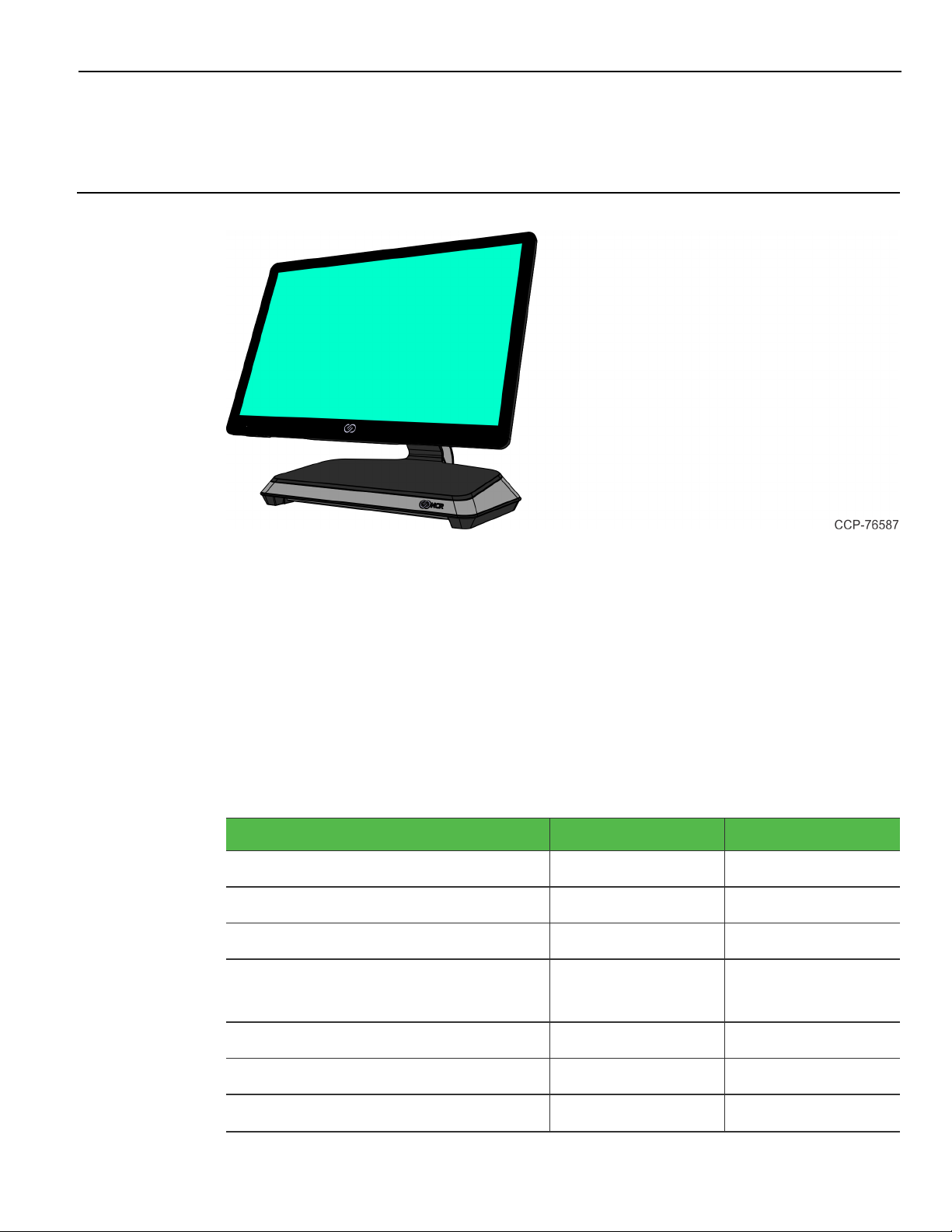
Chapter 1: Product Overview
The NCR CX7 All-in-One POS (7772), powered by Intel’s 8th Generation Coffee Lake
chipset, features a sleek design, packed with superior performance. The new, stylish
design provides a wide range of configuration versatility. The ability to configure with
an I/O board that accommodates environments with more USB devices or an I/O board
that accommodates environments with more serial devices gives customers the
flexibility that prevents additional expansion boards or hubs.
The CX7 offers two I/O configurations for the base:
• Retail I/O Base
• Hospitality I/O Base
I/O Board Connectors Retail I/O Hospitality I/O
USB-C to Head 1 1
12VPowered USB 3 1
24VPowered USB 1 1
Serial 1 x RJ50
1 x DB9
4 x RJ12
2 x RJ45
USB3.0 (5V) 2 2
DisplayPort 1 1
Cash Drawer (12/24 V) 1 (dual port) 2
Page 14

1-2 Product Overview
I/O Board Connectors Retail I/O Hospitality I/O
LAN 1 1
Both I/O boards are connected to the CX7 core motherboard through a single USB TypeC connector. In addition to the integration of the board in the base, each I/O can be
configured for a wall mount solution, pole mount solution, or ordered in a remote
chassis to permit placement under the counter.
Base Models
Model Description
7772-1216-8801 15.6" PCAP RGB w/ Intel Celeron, 8GB DDR4 memory, No
HDD, No Power Supply
7772-1316-8801 15.6" PCAP RGB w/ Intel i3, 8GB DDR4 memory, No HDD,
No Power Supply
7772-1516-8801 15.6" PCAP RGB w/ Intel i5, 8GB DDR4 memory, No HDD,
No Power Supply
Page 15

Product Overview 1-3
Features
Feature Description
Memory F134 8GB, DDR4 2400MHz (Add On)
F136 16GB, DDR4 2400MHz (Add On)
Storage Media F241 SSD 120 GB, M.2 SATA
F242 DUAL SSD 120 GB, M.2 SATA
F253 SSD 240 GB, M.2 NVMe (PCIe)
F255 SSD 480 GB, M.2 NVMe (PCIe)
Port A(Right Side) Features F140 No Peripheral Filler Plate
F141 NCR Encrypted MSR
Port B(Left Side)Features F150 No Peripheral Filler Plate
F151 Biometrics
Port C (Bottom/ Chin)Features F160 No Peripheral Filler Plate
F165 Wireless Card and Antenna
Port DFeatures F450 No Customer Display - Logo Badge
F452 7" Non-Touch LCD (XL7) Customer Display
F453 7" Touch LCD (XL7) Customer Display
Base Display F457 No Base Display Option
Base and Power Supply F033 Base for Retail I/O, Remote Power Supply
F035 Base for Hospitality I/O, Remote Power
Supply
Power Cord F100 US Power Cord
F101 International Power Cord
F102 UK Power Cord
F103 Australia Power Cord
F104 China Power Cord
F105 SEV Power Cord
F106 India Power Cord
F108 Argentina Power Cord
F109 Power Cord 120V Twist Lock
F119 No Power Cord
Page 16

1-4 Product Overview
Optional Features
Optional Feature Description
Ethernet Cable F110 7772 10/100/1000 Ethernet Cable
Page 17

Product Overview 1-5
Operating Systems
The OS image and base platform drivers will be pre-loaded on the solid state drive prior
to shipment. The POS must be configured with a solid state drive.
Product ID Product ID Description
7772-F700 No Operating System Approval
7772-F720 Windows 10 IoT Enterprise 2019 LTSC Value 64 bit
(UEFI) Embedded Operating System
7772-F740 Orderman Windows 10 IoT Enterprise 2019 LTSC
Value 64 bit (UEFI) Embedded Operating System
7772-F790 SUSE Linux Enterprise Server (SLES) 15 64 bit
Operating System
Base client and third-party software are also available on the public NCR Platform
Software Website: http://www.ncr.com/support/support_drivers_
patches.asp?Class=External\display
Configuration
Notes
required
Pre-installed in
the factory
Pre-installed in
the factory
Pre-installed in
the factory
Page 18

1-6 Product Overview
Specifications
Model Specs Good Better Best
Chipset Intel Q370 “Coffee Lake”
Processor Intel® Celeron®
G4900T
Clock Speed 2.9GHz 3.1GHz 2.1GHz
Turbo Boost for Peak
Loads
Level 2 Cache 2MB 4MB 6MB
Thermal Design
Power
AMT No Yes Yes
Intel vPro No No Yes
Image Recovery
Button
Odometer Chip Yes Yes Yes
RAID Support Yes Yes Yes
TPM Yes Yes Yes
N/A N/A Up to 3.5 GHz
35 Watts 35 Watts 35 Watts
Yes Yes Yes
Intel® Core™ i38100T
Intel® Core™ i58500T
Memory
Memory Type DDR4-2133MT DDR4-2133MT DDR4-2133MT
Form Factor SODIMM SODIMM SODIMM
Memory Slots 2 2 2
Standard Memory 8GB (1 x 8GB) 8GB (1 x 8GB) 8GB (1 x 8GB)
Maximum Memory 32GB (2 x 16GB) 32GB (2 x 16GB) 32GB (2 x 16GB)
Storage
SSD - Solid State Drive
(M.2 SATA)
SSD - Solid State Drive
(M.2 NVMe)
SSD - Solid State Drive
(M.2 NVMe)
120GB SSD 120GB SSD 120GB SSD
240GB SSD 240GB SSD 240GB SSD
480GB SSD 480GB SSD 480GB SSD
Page 19
Product Overview 1-7
Model Specs Good Better Best
Dual Solid State Drive
Dual 120GB SSD Dual 120GB SSD Dual 120GB SSD
(M.2 SATA)
Integrated Touch Display
15.6” Projected
Yes Yes Yes
Capacitive
1366 x 768
10-point touch
Brightness 400 nits 400 nits 400 nits
Screen Life 50K Hours to half
brightness
50K Hours to half
brightness
50K Hours to half
brightness
Integrated Speaker Standard Standard Standard
Peripherals
3-track Encrypted
Option Option Option
MSR
Integrated Wireless
Option Option Option
802.11 AC & Bluetooth
Integrated Biometric
Option Option Option
Reader
Imager Option Option Option
2-in-1 Sign-in Device Option Option Option
Consumer Displays
APA customer display Option Option Option
7” Color LCD
Option Option Option
(Touch or Non-touch)
10” Color LCD
Option Option Option
(Touch or Non-touch)
Dimensions/Weight
CX7 terminal with
base
• Dimensions (w x d x h)
14.95” x 7.81” x 12.08”
(379.7 mm x 198.4 mm x 306.8 mm)
• Weight
11.35 lbs (5.15 kg)
Page 20

1-8 Product Overview
Model Specs Good Better Best
CX7 terminal without
base
• Dimensions (w x d x h)
Width 14.95” x 1.26” x 9.32”
(379.7 mm x 32.0 mm x 236.6 mm)
• Weight
5.30 lbs (2.40 kg)
Page 21
Product Overview 1-9
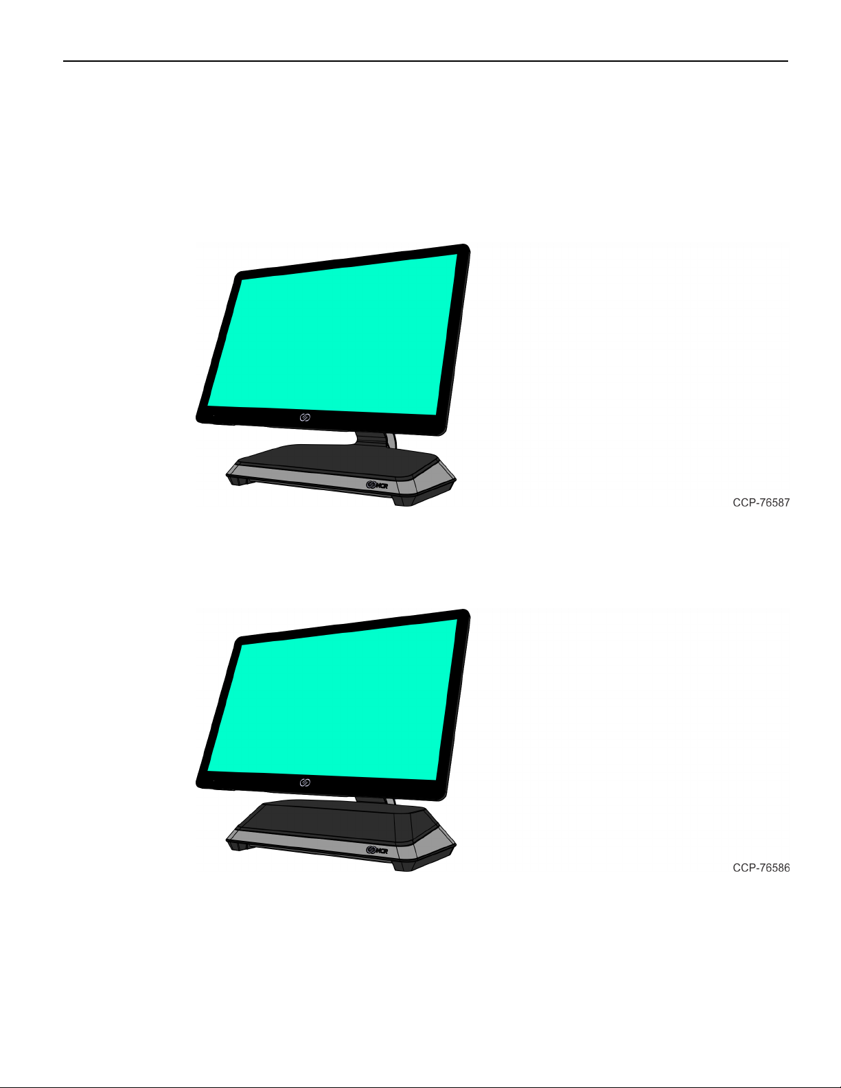
Mounting Configurations
Base with Remote Power Supply (F033/F035)
• with Retail I/O (F033)
• with Hospitality I/O (F035)
Base with Integrated Power Supply
7772-K032 provides an option to permit integration of the power supply in the base.
Page 22
1-10 Product Overview
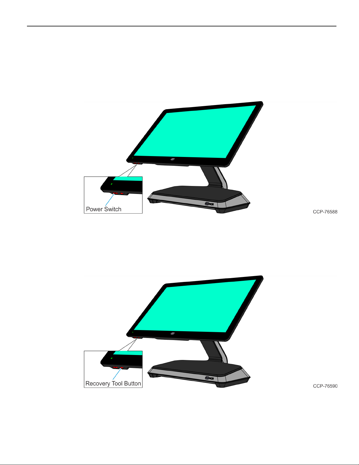
Operator Controls
Power Switch
The Power Switch is located on the bottom of the display. This switch is a momentary
contact, push-on-push-off switch.
Recovery Tool Button
The Recovery Tool Button is for the OS Recovery Tool option. The recessed button is
located on the bottom of the display. The button is a momentary contact, push-on-pushoff switch.
Page 23
Product Overview 1-11
LEDIndicators
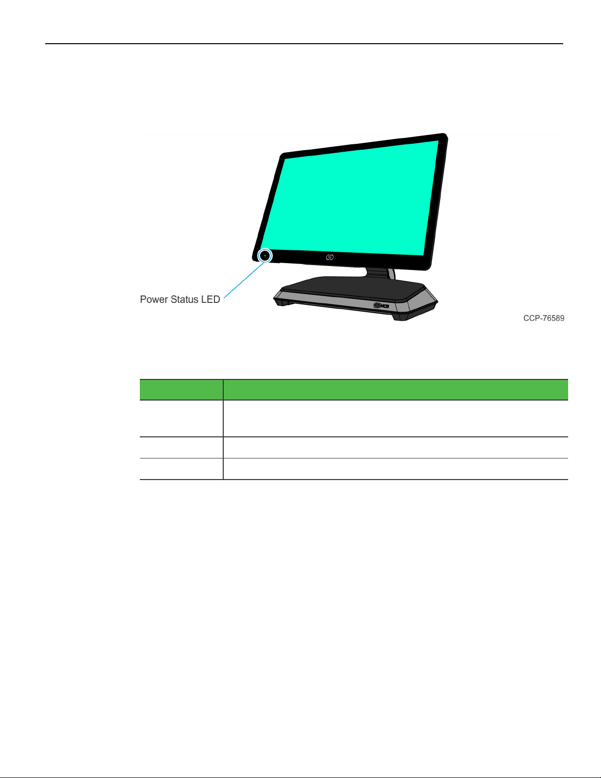
Power Status LED
The Power Status LED, located on the front of the display, has multiple functions as
defined below.
Color Description
Solid Green Terminal is ON and all voltages from power supply and
motherboard are okay.
Blinking Green Terminal is in SUSPEND (S3/S4)mode.
Solid Red Processor over temperature.
Page 24
1-12 Product Overview
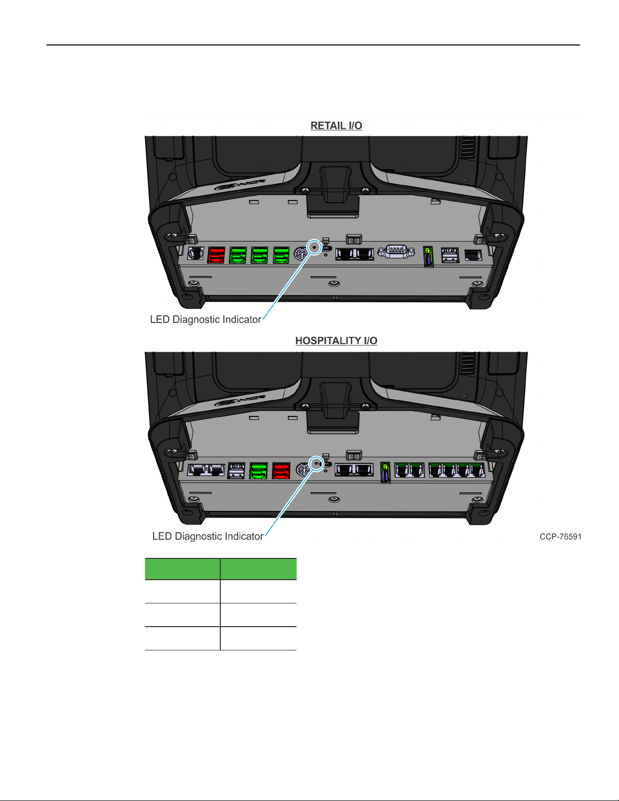
I/O Panel LED
The Status LED is located on the I/O Panel on the Base.
Color Description
Green
Orange
Off
On
S3
Off
Page 25
Product Overview 1-13
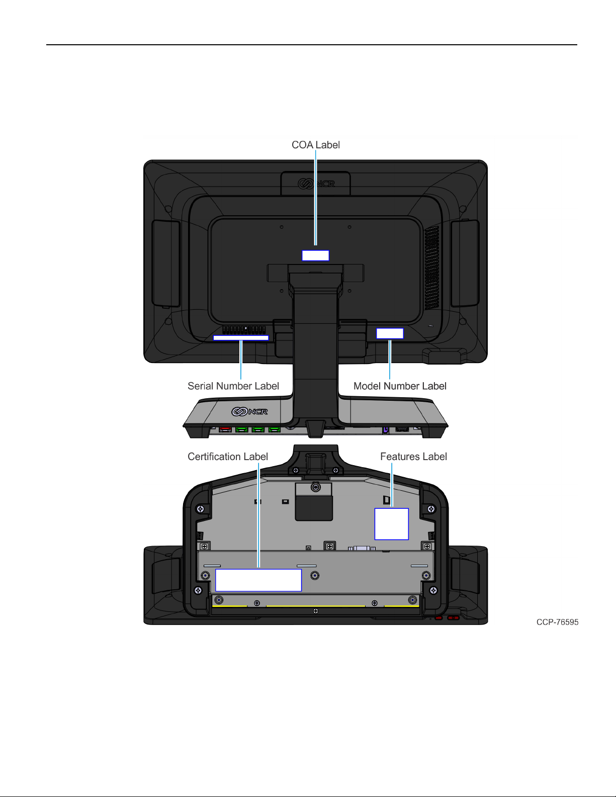
Label Locations
CX7 with Base
Page 26

1-14
Page 27

Chapter 2: Hardware Installation
Installation Restrictions
• The NCR CX7 All-in-One POS (7772) conforms to all applicable legal requirements.
To view the compliance statements see the NCR RealPOS Terminals Safety and
Regulatory Statements (B005-0000-1589).
• Install the CX7 near an electrical outlet that is easily accessible. Use the power cord
as a power disconnect device.
• Do not permit any object to rest on the power cord. Do not locate the CX7 where
the power cord can be walked on.
• Use a grounding strap or touch a grounded metal object to discharge any static
electricity from your body before servicing the CX7 terminal.
Warning: This unit contains hazardous voltages and should only be serviced by
qualified service personnel.
Caution: Do not connect or disconnect the transaction printer while the terminal is on.
This can result in system or printer damage.
Ergonomic Workplace
The NCR CX7 All-in-One POS (7772) has a high–brightness LCD with an anti–glare
screen. For best results, please observe the following when considering the terminal
workplace:
• Avoid direct–glaring and reflective–glaring light. Locate the terminal in a controlled
luminance surrounding. When installed next to windows position the terminal so it
does not reflect the outside light.
• If possible, avoid reflective glaring caused by electric light sources.
• Position the terminal for ideal viewing angles.
Page 28
2-16 Hardware Installation
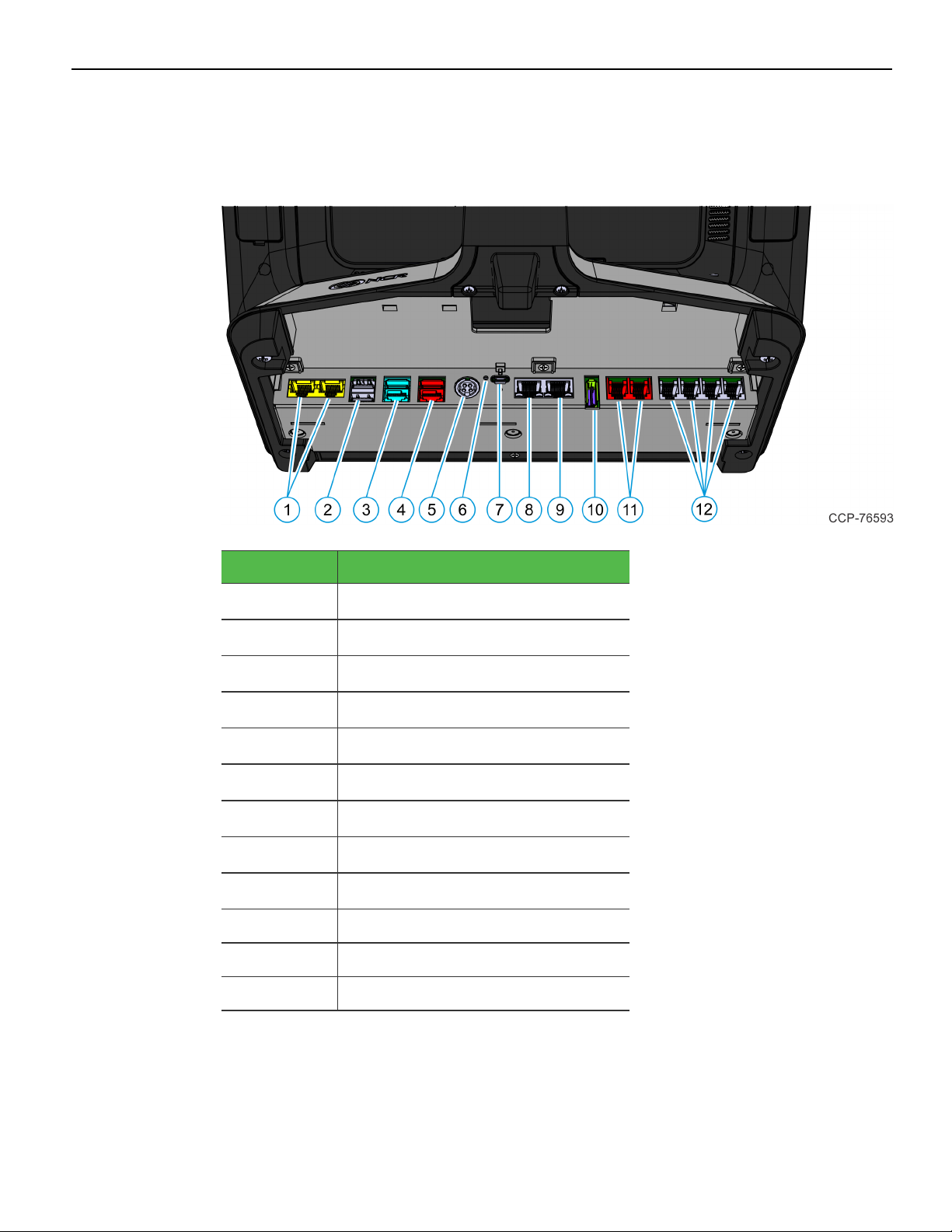
I/O Ports
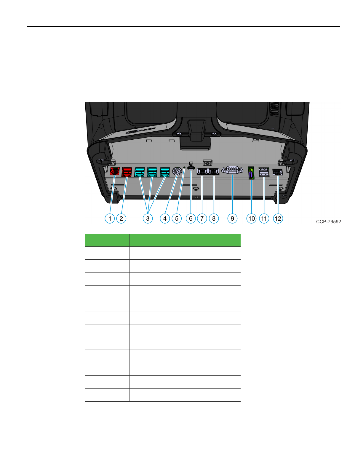
Retail I/O
The following are the default I/O ports for the NCR CX7 All-in-One POS (7772) with a
Retail I/OBase.
Callout Port Name
1 Cash Drawer
2 USB24V
3 USB12V
4 24V Power In
5 LED
6 USB-C
7 LANOut
8 LANIn
9 DB9 Serial
10 DisplayPort
11 Dual USB 3.0
12 RJ50 Serial
Page 29
Hardware Installation 2-17
Hospitality I/O
The following are the default I/O ports for the NCR CX7 All-in-One POS (7772) with a
Hospitality I/OBase.
Callout Port Name
1
2
3
4
5
6
7
8
9
10 DisplayPort
11 Cash Drawer
12 RJ12 Serial
RJ45 Serial
Dual USB 3.0
USB12V
USB24V
24VPower In
LED
USB-C
LANOut
LAN In
Page 30

2-18 Hardware Installation
I/OBoard Connector Pinouts
12V USB +Power
The I/O Board provides latching 12V Powered USB port (Foxconn P/N UB11123-GHT24F or NCR approved equivalent). The 12V Powered USB port is capable of supplying
12V at 2.0A max. The color of the connector is teal.
The 12V of each port is fused with a self-healing poly-fuse (Polytronics Everfuse P/N
SMD2920P300TF/15 or NCR approved equivalent). An overcurrent signal is used to
detect when this fuse is open. This signal is connected to a GPIO on the Super I/O.
Current limiting power switches are provided on the 5V VBUS pins with a limit current
of 1A.
The Retail I/O Board provides three 12V Powered USB ports, while the Hospitality I/O
Board provides one 12V Powered USB port.
Signal Name Pin Pin Signal Name
USBPWR 1 5 GND
USB D– 2 6 +12V
USBD+ 3 7 +12V
GND 4 8 GND
FRAME GND 9 10 FRAME GND
FRAME GND 11 12 FRAME GND
Page 31

Hardware Installation 2-19
24V USB +Power
The I/O Board provides one latching 24V Powered USB port (Foxconn P/N UB11123GHR3-4F or NCR approved equivalent). The 24V Powered USB port is capable of
supplying 24V at 2.3A continuous and 3.0A peak. The color of the connector is red.
The 24V is fused with a resettable fuse (Tyco RUEF250U or NCR approved equivalent).
An overcurrent signal is used to detect when this fuse is open. This signal is connected
to a GPIO on the Super I/O. A separate return line, 24V_RET, is used instead of ground
to provide noise isolation.
Signal Name Pin Pin Signal Name
USBPWR 1 5 24V_RET
USB D– 2 6 +24V
USBD+ 3 7 +24V
GND 4 8 24V_RET
FRAME GND 9 10 FRAME GND
FRAME GND 11 12 FRAME GND
Page 32

2-20 Hardware Installation
Cash Drawer
Cash Drawer Connector for Retail I/O
The Retail I/O Board provides a single 6-position RJ12 connector (Molex 44248-0065 or
NCR approved equivalent).
Pin Signal Name
1 Frame Gnd
2 Solenoid A
3 Drawer A/B
4 +24V/12V
5 Solenoid B
6 Logic Gnd
Page 33

Hardware Installation 2-21
Cash Drawer Connector for Hospitality I/O
The Hospitality I/O Board provides a dual package RJ12 connector. The color of the
connector is red. When using a legacy Y-cable adapter, only Cash Drawer Port A of the
adapter will be functional.
Pin Signal Name
1 Frame Gnd
2 Solenoid A
3 Drawer A/B
4 +24V/12V
5 NC
6 Logic Gnd
Page 34

2-22 Hardware Installation
DisplayPort
The I/O Board provides a 2-lane DisplayPort. Lanes 2 and 3 of the DisplayPort are not
connected internally.
Pin Signal Name
1
2
3
4
5 GND
6 ML_Lane1 (n)
7 ML_Lane2 (p)
8 GND
9 ML_Lane2 (n)
10 ML_Lane3 (p)
11 GND
12 ML_Lane3 (n)
13 CONFIG1
14 CONFIG2
ML_Lane0 (p)
GND
ML_Lane0 (n)
ML_Lane1 (p)
15 AUXCH (p)
16 GND
17 AUXCH(n)
18 Hot Plug Detect
19 Return
20 DP_PWR
Page 35

Hardware Installation 2-23
LAN
The I/O Board provides Gigabit Ethernet support on an RJ45 connector using a passthrough connection to the motherboard. The connector does not feature an LED
indicator.
PowerIn
Both Retail and Hospitality I/O Boards accept +24V DC voltage input from an external
power supply. The Power In connector is a 4-pin DIN - CUI PD-40S or equivalent.
Pin Signal Name
1 GND
2 24V
3 GND
4 24V
Page 36

2-24 Hardware Installation
USB-C
The I/O Board is connected to the motherboard through a non-standard USB Type C
connector. The I/O Board provides a +24V power to the motherboard through the VBUS
lines of the USB-C connector.
Signal Pin Pin Signal
GND A1 B12 GND
USB3.0 TX1+ A2 B11 USB3.0 RX1+
USB3.0 TX1– A3 B10 USB3.0 RX1–
+V (24V) A4 B9 +V (24V)
CC1 (GPIO1) A5 B8 SBU2
USB2.0 A D+ A6 B7 USB2.0 BD–
USB2.0 A D– A7 B6 USB2.0 BD+
SBU1 A8 B5 CC2 (GPIO2)
+V (24V) A9 B4 +V (24V)
Display Port A10 B3 Display Port
Display Port A11 B2 Display Port
GND A12 B1 GND
Since reversibility is not required, the CC1 and CC2 signals will be re-purposed for the
following functions:
Signal Pin Function
CC1 (GPIO1) A5 Power Status from Motherboard
CC2 (GPIO2) B5 Display Port Hot Plug Detect
USB 3.0
The I/O Board provides a dual-stack USB 3.0 Type A connector. Each standard +5V USB
port is capable of supplying 5V at 900mA which is controlled via load switch.
Page 37

Hardware Installation 2-25
DB-9 Serial
The Retail I/O Board provides one full RS-232 serial port through a DB-9 connector. The
port has a shunt to select between +12V (default), +5V, or normal RI functionality.
Maximum power capability is 1A from this port. The power output from this port is
protected by a self-healing fuse.
Pin Signal Name
1 DCD
2 DSR
3 RXD
4 RTS
5 TXD
6 CTS
7 DTR
8 GND
9 RI
RJ12 Serial
The Hospitality I/O Board provides a quad-package RJ12 serial port. The RJ12 port is an
unshielded 6-pin. The color of the connector is black.
Pin Signal Name
1 RTS
2 GND
3 TX
4 RX
5 GND
6 CTS
Page 38

2-26 Hardware Installation
RJ45 Serial
The Hospitality I/O Board provides one dual package RJ45 serial port. The RJ45 port is
an unshielded 8-pin. The color of the connector is yellow.
Pin Signal Name
1 DSR
2 DCD
3 DTR/5V
4 GND
5 RX
6 TX
7 CTS
8 RTS/12V
Page 39

Hardware Installation 2-27
RJ50 Serial
The Retail I/O Board provides one full RS-232 serial port through an RJ50 connector. The
port has a shunt to select between +12V (default), +5V, or normal RI functionality.
Maximum power capability is 1A from this port. The power output from this port is
protected by a self-healing fuse.
Pin Signal Name
1 NC
2 DCD
3 DSR
4 RXD
5 RTS
6 TXD
7 CTS
8 DTR
9 GND
10 RI
Page 40

2-28 Hardware Installation
Installing the Terminal
The terminal can be mounted using the following mounts:
• Base for Retail I/O with Remote Power Supply (F033)
• Base for Hospitality I/O with Remote Power Supply (F035)
This chapter explains how to perform an "Out-of-box" installation of a CX7 configured
with the Base and how to connect optional peripheral devices.
The CX7 comes fully assembled and ready to use. All that is required to install is connect
the AC Power Cord, LAN Cable, and peripheral device cables.
For more information about the CX7 I/O ports, refer to:
• Retail I/O on page16
• Hospitality I/O on page17
Page 41

Hardware Installation 2-29
Connecting ACPower
The CX7 receives power from an external 24V power brick.
Caution: The CX7 requires the NCR 24V power supply that is shipped with the
terminal. Use of other power bricks may cause damage to the unit.
1. Connect the Power Supply cable to the Power In connector on the Base.
2. Connect the AC Power Cord to the Power Supply and to an AC outlet.
Caution: Do not connect or disconnect the Power Cable from the terminal with the
AC Power Cord connected to an AC outlet.
Connecting to a Network
Most business configurations require the terminal to connect to a network. Connecting
to a network enables communicating with other systems and devices also on the
network. Depending on business configurations, connecting to a network may allow
connection to the Internet.
To connect the CX7 terminal to a network, connect the 10/100/1000 Ethernet cable to the
port labeled LAN In on the I/Opanel of the Base. The other end of the 10/100/1000
Ethernet cable should be connected into the network hub.
Note: Consult with your business Information Technology (IT) representative to
determine the available connection, and to locate the network hub.
Page 42

2-30 Hardware Installation
Installing the Cash Drawer
The Cash Drawer can be connected to the Cash Drawer connector on the Base.
Page 43

Hardware Installation 2-31
Installing the Second Cash Drawer
A second Cash Drawer can be installed on terminals with a:
• Retail I/O Base — For more information, refer to Second Cash Drawer for Retail I/O
below.
• Hospitality I/O Base — For more information, refer to Second Cash Drawer for
Hospitality I/O on the next page.
Second Cash Drawer for Retail I/O
The Retail I/O supports a 2-drawer configuration with a Dual Cash Drawer Cable.
Connect this cable to the Base or transaction printer cash drawer connector.
There are two versions of the Dual Cash Drawer Cable for the Retail I/O:
• 1432-C516-0009 (24V)
• 1432-C517-0009 (12V)
Caution: The two cables look very similar. Make sure to use the correct one.
Connecting the wrong cable can cause system damage.
Page 44

2-32 Hardware Installation
Second Cash Drawer for Hospitality I/O
24VCash Drawers
24VCash Drawers can be connected to the Cash Drawer connectors on the Hospitality
I/O.
Page 45

Hardware Installation 2-33
12VCash Drawers
Single port adapter cables (1432-C828-0010) are required to connect 12VCash Drawers to
the Hospitality I/O.
Page 46

2-34 Hardware Installation
Installing the Transaction Printer
Warning: Do not hot plug the printer when connecting the POS terminal. Always
power down the POS prior to connecting the printer to prevent damage to the POS
and/or printer.
Connect the Powered USB Printer Interface Cable to the USB Connector and Power
Connector on the printer and to the 24V Powered USB Connector on the Base.
Page 47

Hardware Installation 2-35
Powering Up the Terminal
1. After installing the terminal, power up the system by pressing the Power Switch,
which is located on the bottom of the display.
The system installs the system devices, system settings, and then reboots to continue
setup. Complete the System Setup. This varies from OS to OS but the following is
typical.
2. The initial setup procedures are performed:
• Starting Windows
• Preparing the computer for first time
• Checking video performance
3.
Accept the License Terms Agreement.
Note: Depending on the installed operating system and the selected settings, the
amount of time it takes to boot up may vary.
Page 48

Chapter 3: Operation and Cleaning
Touchscreens
The NCR CX7 All-in-One POS (7772) has a Projected Capacitive (PCap) Touchscreen.
Projected Capacitive Touchscreen
PCap touchscreens have all the benefits of normal capacitive touchscreens and more.
• Fast processing of tough information
• High sensitivity (use conductive pencils, with hands, and with thin gloves)
• Multi-touch capability (10-finger)
• High resolution
• Improved legibility and display brightness due to optimal light transmission
In addition, the technology of PCap touchscreens is characterized by significantly
higher robustness and stability than common capacitive touchscreens because the active
touch surface is located on the back side of the touchscreen. instead of the front side.
Therefore, the active surface is not directly touched and does not wear off by normal
use.
Since most surface contamination do not cause interference to the touchscreen the NCR
CX7 All-in-One POS (7772) can be used in public or severe environmental conditions.
Using the PCap Touchscreen
The PCap touchscreen responds to the lightest touches. Touching with a single finger
resembles the left mouse button. Two fingers are used to zoom IN (fingers brought
together) or zoom OUT (fingers pulled apart). Circular motion can be used to rotate an
element on the screen. This function must be supported by either the Operating System
or the application.
Cleaning the Touchscreen
1. Using a soft cloth dampened with isopropyl alcohol or a mild non-abrasive soap &
water solution, gently wipe the touchscreen clean.
2. Wipe the screen and edges dry.
3. Make sure the glass and screen edges dry completely before using the unit.
4. Do not use sharp objects to clean around the edges of the touchscreen.
Page 49

3-37 Operation and Cleaning
Magnetic Stripe Reader
The Magnetic Stripe Reader (MSR) for the CX7 is an ISO 3-Track (Encrypted).
The card reading is bi-directional and can be mounted on Port A(right side) of the
display.
Using the MSR
Swipe the card through the slot in the MSR in a quick and steady movement. The
magnetic stripe must be facing up and with the stripe in the slot.
Care of Cards
• Cards should never come in contact with liquids.
• Cards should never be bent or folded in any way.
• Cards should never come in close proximity of a magnetic field.
Card Thickness
The MSR module accepts standard cards within the thickness range of 0.68–0.84 mm.
Page 50

Operation and Cleaning 3-38
Biometrics Fingerprint Reader
High quality fingerprint templates are imperative for the security of the biometric
security system. Low quality fingerprint templates can impact future read rates.
Therefore, using the Biometrics Module should be done very carefully. In case of
inexperienced users who are using the module for the first time, the process should be
assisted (guided) by an administrator or experienced user.
Using the Biometrics Reader
Place your thumb/finger flat and straight on the sensor. If this is not possible, try to
place your thumb/finger on the sensor in the same angle every time.
Under normal usage conditions dirt, residue, oils, and other materials can collect on
users’ fingers. This can possibly cause poor collection of fingerprint data, which can
cause performance degradation. For the best results it is recommended that the user
keep their fingers relatively clean and free of residues that may alter the sensor
performance.
Scotch tape can be used to clean fingers. Adhere the tape to the finger and then pull it
off.
Page 51

3-39 Operation and Cleaning
Cleaning the Sensor
Before each authentication, it is recommended that the user first clean the sensor. Place
adhesive tape onto the sensor and then pull it off. This assures that residue from
previous usage is removed.
Caution: Do not use abrasive materials to clean the sensor.
Software Drivers
The CX7 biometrics reader is a digitalPersona U.ARE.U 4500 Module. Please visit the
Crossmatch website for drivers and application developer tools.
https://www.crossmatch.com/company/support/request/
Page 52

Operation and Cleaning 3-40
Cleaning the Cabinet
1. Disconnect the unit from the power outlet before cleaning.
2. Use a cloth lightly dampened with a mild detergent.
3. Do not use alcohol (methyl, ethyl, or isopropyl) or any strong dis-solvent. Do not use
thinner or benzene, abrasive cleaners, or compressed air.
Warning: Do not use any other types of cleaners such as vinegar, solvents,
degreasers, or ammonia-based cleaners. These can damage the unit.
4. Avoid getting liquids inside the unit. If liquid does get inside, have a qualified service
technician check it before you power it on again.
5. Remove external dust around the cooling vents.
Page 53

3-41 Operation and Cleaning
Cleaning the Cooling Vents
The air vents on the back of the terminal should be cleaned periodically to maintain
optimum cooling for the CPU.
Use the hose attachment on a standard household vacuum cleaner to remove the dust
from the vents.
Page 54

Chapter 4: Disk Image Backup and Recovery
Tool
Introduction
This section discusses procedures on how to backup or recover the POS image. The
terminal has a recovery tool that performs a complete backup of the whole HDD/SSD.
This includes the operating system, all files, data and the database itself if it is installed
on the HDD/SSD, making an exact duplicate of everything contained on the terminal.
The Recovery Tool uses the Windows Image (.WIM) file format to store the OS image.
This is a file-based format for use with the ImageX and DISM tools that Microsoft
created for use with Windows Vista and later OS versions. The format can also be used
to capture and restore XP-based OS images. More information on the ImageX tool and
.WIM format can be found at:
http://technet.microsoft.com/en-us/library/cc722145(WS.10).aspx
The Recovery Tool is designed to create a complete backup of, or restore, a previously
saved image to the terminal.
The Recovery Tool offers the following functions and features:
• Multi-language support for the following languages: EN; DE; FR; IT; ES
• Check and Repair Disk
• Backup the System
• Restore the System to a previous state
• Password Protection
• Network support
You can save and restore your backup from different locations:
• Network
• USB Drive
• Hard Drive/Solid State Device (if present on the terminal)
Page 55

4-43 Disk Image Backup and Recovery Tool
Running the Recovery Tool
Starting the Recovery Tool
The Recovery Tool Button is located on the bottom of the display.
1. Begin with the terminal OFF.
2.
Press and hold the recessed Recovery Tool Button. While holding the Recovery
Tool Button, momentarily press the Power Switch.
3.
Continue holding the Recovery Tool Button until the NCRlogo has flashed on the
screen.
Page 56

Disk Image Backup and Recovery Tool 4-44
Main Screen
When the terminal boots the Main Screen is displayed.
Save or Load Image
This button opens the Backup and Recovery screen.
Change Settings
This button opens a dialog screen to let you set/change the password and to configure
the network settings.
Shutdown or Reboot
This button opens the screen to properly Shutdown and Reboot the POS.
System Information
This is where useful information of the POS is displayed, such as Serial Number and
Image Names.
Page 57

4-45 Disk Image Backup and Recovery Tool
Save or Load Image
This function is used to either Save or Load an image from a device.
1.
On the Main Screen, select Save or Load Image.
2.
Enter the Password. The factory default password is Recovery1234.
Page 58

Disk Image Backup and Recovery Tool 4-46
Saving an Image
The Select Image Location screen displays a terminal with three sets of In/Out arrow
buttons, indicating the direction of data flow when selected. Arrows pointing away from
the terminal are used to Save images to a device. Arrows pointing towards the terminal
are used to Load an image.
Recovery Partition Size
The size of the Recovery Partition is limited to 8GB on the local drive. The USB and
network options can be used to store / backup larger images. The total size is comprised
of the base factory image + the user and site backups and the roughly 300MB of space
used by WinPE and apps. USB/Network backups are limited only by the hardware that
they are being stored to.
After the factory image is copied into the Recovery Partition, there is approximately 3GB
remaining in the 8GB partition. Any data stored as an incremental backup to this
location is compressed. A typical, large POS software installation will not outpace the
constraints of the local storage.
Page 59

4-47 Disk Image Backup and Recovery Tool
Backups to separate slots in the Recovery Tool only increase the total storage required by
the amount of data added to the image. When the contents of the OS partition become
too large to store in the 8GB local Recovery Partition, then one of the alternate storage
methods available (USB or network) should be used to store backups.
Output Options
There are three output options:
• Hard Disk Drive/Solid State Device
• USB Device
• Network
Note: Windows 7 images require a minimum of 4GB available on the Network,
Local Drive, or USB drive. POSReady requires a minimum of 2GB. Make sure there
is enough space available on the storage media. Image sizes vary depending on
applications and database sizes.
1. Select the arrow that points to the desired output.
Example: Select the USB Save Button.
Page 60

Disk Image Backup and Recovery Tool 4-48
2.
Select the USB Button.
If this is the first backup performed on this POS, the image is automatically saved as
a Site backup.
Page 61

4-49 Disk Image Backup and Recovery Tool
If a backup already exists, you have the choice of performing either a Site or User
backup.
• Site Image – Use this option immediately after all application components have
been loaded and set up for initial operation, or for base image updates.
• User Image – Use this option for routine day-to-day or periodical backups.
Note: Site and User backups are separate independent backups.
The image information is updated with the new image date.
Page 62

Disk Image Backup and Recovery Tool 4-50
Loading An Image
Caution: Do NOT remove power during an Image Load. Complete the Operating
System setup and then shut down Windows properly. Removing power prematurely
will corrupt the image and display various messages like "Windows failed to load" or
"missing or corrupt registry". If this happens you can do an Image load of the Factory
image with the Recovery Tool.
1. Select the arrow that points from the desired load device to the terminal.
Example: Select the USBLoad Button.
2.
Select the USB Button.
Page 63

4-51 Disk Image Backup and Recovery Tool
If you are loading from a network, the Select a Network Drive dialog screen will open.
3. Select the Image Type.
• User Image – Most recent routine backup.
• Site Image – Image of the terminal after application components were loaded.
• Factory Image – The NCR Base Image as shipped from the factory.
Page 64

Disk Image Backup and Recovery Tool 4-52
4.
Select Yes to apply the image.
Caution: All the information in the current productive/working image on the drive
is lost with this operation!
A progress bar is displayed as the image is applied.
Page 65

4-53 Disk Image Backup and Recovery Tool
A message is displayed when the load is complete.
5.
Reboot the POS.
Page 66

Disk Image Backup and Recovery Tool 4-54
Change Settings
On the Main Screen, select Change Settings.
There are four functions available on the Change Settings screen:
• Change Network Settings
• Change Password
• Replace Recovery Image
• Change Language
Page 67

4-55 Disk Image Backup and Recovery Tool
Change Network Settings
1.
On the Change Settings Screen, select Change Network Settings.
2.
Enter the network configuration settings and then select Save.
Page 68

Disk Image Backup and Recovery Tool 4-56
Change Password
1.
On the Change Settings Screen, select Change Password.
2.
Enter the current password and the new password, and then select Enter.
If you have forgotten or lost the password, select Lost Password. A unique code is
generated that you can provide to NCR Support to receive a new temporary
password.
Page 69

4-57 Disk Image Backup and Recovery Tool
Replace Recovery Image
This feature is used to update the Recovery Tool and the environment that it runs in.
1.
On the Change Settings Screen, select Replace Recovery Image.
2. Select the source of the Recovery Image.
3. Complete the image replacement in the same manner as with the POS Site/User
image restore procedures.
Page 70

Disk Image Backup and Recovery Tool 4-58
Change Language
1.
On the Change Settings Screen, select Change Language.
2. Select the language of choice.
Page 71

4-59 Disk Image Backup and Recovery Tool
Creating a Disk Image
This terminal has a Recovery Button that permits end users to quickly restore a disk
backup from a hidden partition on the NCR system storage. To utilize this valuable
feature, the image must be created using NCR tools. Tools are available from NCR at:
http://www5.ncr.com/support/support_drivers_patches_
radiant.asp?Class=Hospitality/GenDrivers_display
From this site, download the following:
• ImagingSuite_5.3.0.3.zip (or later) – The Imaging Suite package consists of three
primary parts:
- A Server application for local area network imaging
- A Client application that runs on the target or source machine where images will
be applied to or captured from
- A customized version of Windows PE 3.1 boot OS environment from which the
client application will be run
• Imaging Suite User Guide – This document provides a general overview of the
Imaging Suite package, how to configure the system to run it, and how to use the
applications to capture and apply system images.
Page 72

Chapter 5: Configuring a Second SSD for RAID
Introduction
This chapter discusses how to add a second hard drive and configure a RAID system
using the Intel® Rapid Storage Technology.
The Intel® Rapid Storage Technology provides new levels of protection, performance, and
upgradeability for the CX7 platform. Whether using one or two hard drives you can
take advantage of enhanced performance and lower power consumption. When using
two drives you can have additional protection against data loss in the event of hard
drive failure.
Valuable digital memories are protected against a hard drive failure when the system is
configured for one of the fault-tolerant RAID levels: RAID 1 or RAID 5. By seamlessly
storing copies of data on one or more additional hard drives, any hard drive can fail
without data loss or system downtime. When the failed drive is removed and a
replacement hard drive is installed, data fault tolerance is easily restored.
Page 73

5-61 Configuring a Second SSD for RAID
Configuring a RAID System
RAID Systems can be installed on the CX7 if the 7772-F242 RAID - Dual M.2 120GB SSD
feature is present.
To install and configure a RAID system, perform the following steps:
1. Install the primary SSD.
2. Load the NCR Gold Drive.
3. Install the second SSD in the terminal.
4. Run the Intel® Rapid Storage Technology Manager.
Start → All Programs → Intel → Intel® Rapid Storage Technology
5.
Both disks should be recognized in the Main Screen. Select the Create button.
Page 74

Configuring a Second SSD for RAID 5-62
6. Select the type of RAID volume you want to install. NCR supports RAID 1 and RAID
0 volume types.
RAID 1: Combines two disks to create a volume where each disk stores an exact
copy of the data and provides real-time redundancy.
RAID 0: Combines two disks to create a volume where data is broken down into
strips that are distributed across both disks.
7.
Select Next.
Page 75

5-63 Configuring a Second SSD for RAID
8.
Enter a Volume Name (user preference).
9. Select the check boxes for both disks.
RAID 0 Only: Specify the amount of space to be used by the new RAID volume.
Use the slider to enter a percentage.
Note: If you create a volume that uses less than 100% of the hard drive space, you
may create a second RAID volume to use the remaining space.
10.
Select Next.
Page 76

Configuring a Second SSD for RAID 5-64
11.
Select Create Volume to start the volume migration.
12.
A window is displayed indicating the volume was created successfully. Select OK to
close the window.
Page 77

5-65 Configuring a Second SSD for RAID
The status of the migration is displayed, showing the progress. This can take 1 - 3
hours to complete.
Page 78

Chapter 6: Power Management
The BIOS supports the Advanced Configuration and Power Management Interface
(ACPI) 3.0 specification. A key feature of ACPI is that the operating system, not the
BIOS, configures and implements power management. The CX7 terminal supports the
Global system power states defined by ACPI.
Computer States
G3 Mechanical Off
A computer state that is entered and left by a mechanical means
Example: Turning off the system's power through the movement of a large red switch.
Various government agencies and countries require this operating mode. It is implied
by the entry of this off state through a mechanical means that no electrical current is
running through the circuitry and that it can be worked on without damaging the
hardware or endangering service personnel. The OS must be restarted to return to the
Working state. No hardware context is retained. Except for the real-time clock, power
consumption is zero.
G2/S5 Soft Off
A computer state where the computer consumes a minimal amount of power. No user
mode or system mode code is run. This state requires a large latency in order to return
to the Working state. The system's context will not be preserved by the hardware. The
system must be restarted to return to the Working state. It is not safe to disassemble the
machine in this state.
G1 Sleeping
A computer state where the computer consumes a small amount of power, user mode
threads are not being executed, and the system appears to be off (from an end user's
perspective, the display is off, and so on). Latency for returning to the Working state
varies on the wake environment selected prior to entry of this state (for example,
whether the system should answer phone calls). Work can be resumed without
rebooting the OS because large elements of system context are saved by the hardware
and the rest by system software. It is not safe to disassemble the machine in this state.
Page 79

6-67 Power Management
G0 Working
A computer state where the system dispatches user mode (application) threads and they
execute. In this state, peripheral devices (peripherals) are having their power state
changed dynamically. The user can select, through some UI, various
performance/power characteristics of the system to have the software optimize for
performance or battery life. The system responds to external events in real time. It is not
safe to disassemble the machine in this state.
ACPI Sleep States (S0 - S5)
Under the G1 sleeping state ACPI defines levels of system sleep state support. The CX7
supports the following sleeping states:
• S0: Normal Powered-On state
• S1 (Standby): The S1 sleeping state is a low wake latency sleeping state. In this state,
no system context is lost (CPU or chip set) and hardware maintains all system
contexts.
Note: The CX7 does not support S1 state. Turning off the backlight and hard drives
provides the equivalent power savings (due to Intel's processor C-states feature) at
nearly zero latency.
• S2: Not supported
• S3 (Suspend to Ram): The S3 sleeping state is a low wake latency sleeping state. This
state is similar to the S1 sleeping state except that the CPU and system cache context
is lost (the OS is responsible for maintaining the caches and CPU context). Control
starts from the processor's reset vector after the wake event. In NCR systems, during
S3, power is only provided to the USB 3.0 ports.
Note: When the terminal resumes from an S3 state, all the USB devices reenumerate. This causes speaker tones as if they were disconnected and then
reconnected. This does not present a problem and the USB devices will continue to
operate correctly.
Requirements for S3 support:
• O/S must be built on a system with S3 enabled in the BIOS
• Some peripherals may not be S3 capable, which can prevent the system from
entering S3 state.
• S4 (Suspend to Disk): The S4 state is the lowest power, longest wake latency sleeping
state supported by ACPI. In order to reduce power to a minimum, it is assumed that
the hardware platform has powered off all devices. Platform context is maintained.
Requirements for S4 support:
• O/S must be built on a system with S3 enabled in the BIOS
Page 80

Power Management 6-68
• Some peripherals may not be S4 capable, which can prevent the system from
entering S4 state.
Reference the ACPI Specification for details.
Peripherals: ACPI defines power states for peripherals which are separate from the
system power state. The device power states range from D0 (fully-on) to D3 (off) It is
the responsibility of the driver developer for each peripheral to define and support
the available power states.
Power State S0 Working S0 Idle,
Backlight
Off,
SSDIdle
Supported:
Y Y Y Y Y Y
Y/N
Description Fully
Functional**
Video
Backlight
Off, SSD
Idle
S3 Suspend
to RAM
Video
Backlight
Off, SSD
Idle, Cache
Flush,
Memory in
Slow
Refresh,
CPUHalted
S4
Hibernate
Video
Backlight
Off, SSD
Off, Cache
Flush,
Memory
data to
SSD,
CPUHalted
S5 Soft
Off
OFF
Some
devices
remain
powered
by
standby
voltage
(LAN,
ME-AMT,
USB) to
allow
wake-up
S0 Idle,
Backlight
on
Video
backlight
on
Power
On On Powered
Supply
Status
Power Consumption
Celeron
42.3W 16.4W 2.9W 2.5W 2.5W 25.6W
G4900T
Core i3–
62.2W 17.4W 3.25W 3.0W 3.0W 24.9W
8100T
Core i5–
63.9W 17.4W 3.25W 3.0W 3.0W 24.9W
8500T
Wake Options
Down*
Powered
Down*
Powered
Down*
On
Page 81

6-69 Power Management
Power
N/A Y Y Y Y Y
Switch
Touch N/A Y Y N N
USB
N/A Y Y N N Y
Keyboard
USB Mouse N/A Y Y N N Y
LAN (magic
N/A Y Y Y Y Y
packet)
RTC Alarm N/A Y Y Y Y Y
Serial Port
N/A Y N N N Y
(RI)
Note: Power consumption based on the following configuration: 16GB RAM x2, 240 GB SSD x2
*Maintains small voltage to support wake circuits.
**Passmark Burn in test. This represents a maximum use case. Actual customer usage will differ.
Y
Page 82

Power Management 6-70
Enabling Wake on LAN
In order for Wake on LAN to function, the Network driver must be enabled (factory
default).
1.
Right-click on Start, then select Device Manager.
Page 83

6-71 Power Management
2.
Select Network adapters.
3.
Right-click Intel(R) Ethernet Connection I219-LM >> Properties.
Page 84

Power Management 6-72
4. Under the Advanced tab, Wake on Magic Packet and Wake on Pattern Match should be
enabled. Select OK after making any changes.
5. Under the Power Management tab, Allow this device to wake the computer option box
should be checked. Select OK after making any changes.
Page 85

Chapter 7: BIOS Setup
Entering Setup
1. Connect an alphanumeric USB keyboard to the terminal.
2. Apply power to the terminal.
3.
When you see the NCR logo displayed, press [Del] or [F2].
Selecting Menu Options
The following keyboard controls are used to select the various menu options and to
make changes to their values.
• Use the arrow keys to select (highlight) options and menu screens.
• Use the [Enter] key to select a submenu.
• Use the [+] and [-] keys to change field values.
• To view help information on the possible selections for the highlighted item, press
[F1].
• To save the changes, move the cursor to the Save and Exit Menu, select Save
Changes & Reset, and press [Enter].
Restoring Factory Settings
To reset all values to their default settings, press [F3] and then [Enter] when the
confirmation message is displayed. The terminal automatically loads the BIOS default
values. To save the factory default values, go to the Save and Exit Menu, select Save
Changes & Reset, and select [Enter].
Page 86

7-74 BIOS Setup
BIOS Default Settings
NCR BIOS Version: R110-01
Advanced Menu
► ACPISettings
ACPI Sleep State [S3 (Suspend to RAM)]
State After G3 [Last State]
► NCR POS
Port B Display Mode [DP]
F8 BBS Boot Menu [Enabled]
Bluetooth Controller [Enabled]
WiFi Controller [Enabled]
ONESHOT Control [Disabled]
► Trusted Computing
TPM Support [Enabled]
Pending operation [None]
► S5 RTC Wake Settings
Wake System with Fixed Time [Disabled]
► CPU Configuration
Intel (VMX) Virtualization
C states
► Thermal Configuration
DTS SMM [Disabled]
► SATA Configuration
SATA Mode Selection [RAID]
PCIe Storage Dev On Port 9 [RSTControlled]
[Enabled]
[Disabled]
► AMT Configuration
AMT support [Disabled]
Page 87

BIOS Setup 7-75
► H/W Monitor (Smart Fan 1 Mode)
CPU Smart Fan Mode [Automatic Mode]
Fan Off Temperature Limit 20
Fan Start Temperature Limit 35
Fan Full Speed Temperature Limit 80
Fan Start PWM 20
PWM Slope Setting [3 Duty]
► H/W Monitor (Smart Fan 2 Mode)
CPU Smart Fan Mode [Automatic Mode]
Fan Off Temperature Limit 25
Fan Start Temperature Limit 35
Fan Full Speed Temperature Limit 80
Chipset Menu
Fan Start PWM 20
PWM Slope Setting [3 Duty]
► South Bridge
Azalia HD Audio [Enabled]
► USBControl
USBControl 1 [Enabled]
USBControl 2 [Enabled]
USBControl 3 [Enabled]
USBControl 4 [Enabled]
USBControl 5 [Enabled]
USBControl 6 [Enabled]
USBControl 7 [Enabled]
USBControl 8 [Enabled]
USBControl 9 [Enabled]
Page 88

7-76 BIOS Setup
Security Menu
Administrator Password [None]
User Password [None]
Boot Menu
Boot Configuration
Setup Prompt Timeout 3
Bootup NumLock State [On]
Display POST Logo [Enabled]
FIXED BOOT ORDER Priorities
Boot Option #1 [Hard Disk]
Boot Option #2 [Network]
Boot Option #3 [USB Key]
Boot Option #4 [USB Hard Disk]
Boot Option #5 [USB CD]
Boot Option #6 [USB Floppy]
Boot Option #7 [CD/DVD]
Boot Option #8 [USBLAN]
Page 89

Chapter 8: BIOS Updating Procedure
Introduction
The BIOS is located in the Serial Peripheral Interface (SPI) chip on the processor board.
This chapter discusses procedures on how to update the terminal SPI and/or BIOS. The
update software is distributed via the NCR Website:
http://www5.ncr.com/support/support_drivers_patches.asp
The BIOS update can be performed using the following methods:
• Bootable USB Memory Device
• Windows Flash Executable
Prerequisites
The following are required to perform a SPI/BIOS update:
• USB Alphanumeric Keyboard
• BIOS Software. Download from the NCR
Website:http://www5.ncr.com/support/support_drivers_patches.asp
USB Flash Key update prerequisites
• USB Flash Key with sufficient space for the update files.
• Access to a USB port on the terminal to be updated that is enabled in the BIOS (via
BIOS setup).
Windows Flash Executable update prerequisites
• There should be no other programs running while the BIOS/SPI is updating.
• The Windows Flash Executable is designed to run from an Administrator account.
Page 90

8-78 BIOS Updating Procedure
SPI/BIOS Updating Procedures
Using the Bootable USB Flash Key
1. Create a USBFlash Drive by installing the BIOS update package to this USB key.
Note: The USB flash drive disk size must be more than 512MB.
Linux PC
Use “dd” Linux command to deploy image in USB key:
sudo dd if=/CX7-BIOS_update_T06.iso of=/dev/sdX
Windows PC
Download the Rufus Tool from the Rufus Website: https://rufus.ie/ and use the tool to
deploy image into USB key.
a. Select the device from the Device drop-down list.
Page 91

BIOS Updating Procedure 8-79
b.
Press Select to choose the image from the Boot Selection drop-down list.
Page 92

8-80 BIOS Updating Procedure
c.
Press Start to load the image.
Page 93

BIOS Updating Procedure 8-81
d.
When the load is complete, select Close.
2. Insert the CX7 USBFlash Drive into the USB Port.
3.
Press [F8] during startup to bring up the Boot Menu.
4. Select the USB device to boot the CX7 BIOS flash key. An option menu will load.
5.
Select option [1] to update BIOS with DMI preserved.
Note: After the update has completed and the terminal is rebooted, the terminal may
reboot additional times as it powers up. This is normal and expected behavior due to the
nature of the features of the BIOS/SPI.
Page 94

8-82 BIOS Updating Procedure
Using the Windows Flash Executable
Note: Close all running programs prior to updating the BIOS.
To run the executable, follow these steps:
1.
Right–click on the file and select Run as administrator.
2. When prompted, press a key to initiate the flash update. The terminal will reboot
after the flash process has completed.
Caution: The reboot is important to ensure the BIOS initializes properly. Do not
interrupt the reboot process.
Page 95

Chapter 9: Initial Terminal Imaging
Introduction
Factory default HDD/SSD images for the CX7 are distributed on bootable auto-imaging
USB Flash Drive media. The following procedures describe how to apply/restore an
image on the terminal.
Warning: Using this procedure will replace any previously stored OS images
created using the Disk Image Backup and Recovery Tool.
Note: A USB Keyboard is required to perform this operation.
Imaging Procedure
1. Connect the USB flash drive to the target terminal that you wish to image.
2. Connect a USB keyboard to the terminal.
3. Power on the terminal and boot from the USB Flash Drive. This can be done by
pressing F8 during the boot and choosing the USB option (NCR), or by entering
BIOS Setup and changing the boot order.
4.
The system boots in the Windows PE OS environment. Press Y on the keyboard at
the confirmation prompt to re-image the terminal.
5.
When the imaging process is complete, enter Exit on the keyboard to reboot the
system.
6. After the reboot, remove the USB Flash Drive and disconnect the keyboard.
 Loading...