

Page 1

7403-K131/132/133/K138
Memory Modules
Kit Instructions
Issue C
Page 2

Issue Date Remarks
A
Nov 2008
First issue
B
Mar 2011
Added 7409, 7600, and 7610 support
C
Mar 2013
Added K138 (4 GB)
Revision Record
Page 3

Introduction
7403-K131
497-0460358
DDR2, 512 MB DIMM, 800 MHz
7403-K132
497-0460359
DDR2, 1 GB DIMM, 800 MHz
7403-K133
497-0460360
DDR2, 2 GB DIMM, 800 MHz
7403-K138
497-0477587
DDR2, 4 GB DIMM, 800 MHz
1
These kits provide the various increments of memory available for the terminal. Refer
to the proper terminal section for installation procedures.
Kit Contents
RealPOS 70
SelfServ 60 (7409) Installation Procedures
RealPOS 40 (7600) Installation Procedures
RealPOS 25 (7610) Installation Procedures
The content of the kit is as followed.
Kit No. Memory Part No. Description
Note: The RealPOS 40 (7600) and RealPOS 25 (7610) come standard with 1GB of
memory and support a single DIMM slot. Therefore only the 2 GB kit applies to these
terminals.
XRT (7403) Installation Procedures
Page 4
2
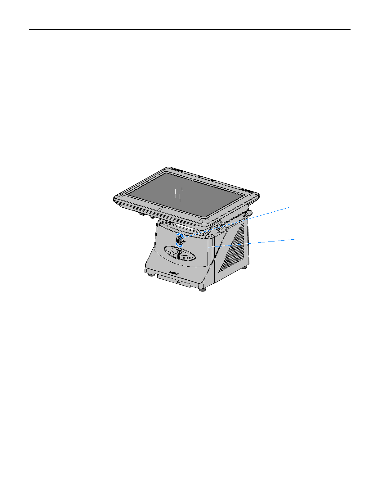
26124
Security Key
Front Base Cover
RealPOS 70XRT (7403) Installation Procedures
Caution: Static Electricity Discharge may permanently damage your system.
Discharge any static electricity build up in your body by touching your computer’s
case for a few seconds. Avoid any contact with internal parts and handle cards only
by their external edges.
1. Disconnect power to the terminal.
Caution: Disconnect the AC power cord before disassembling the terminal. The
ON/OFF switch does NOT remove power to the unit.
a. Remove the Front Cover.
b. Insert the Security Key and turn it 90 degrees clockwise.
Page 5
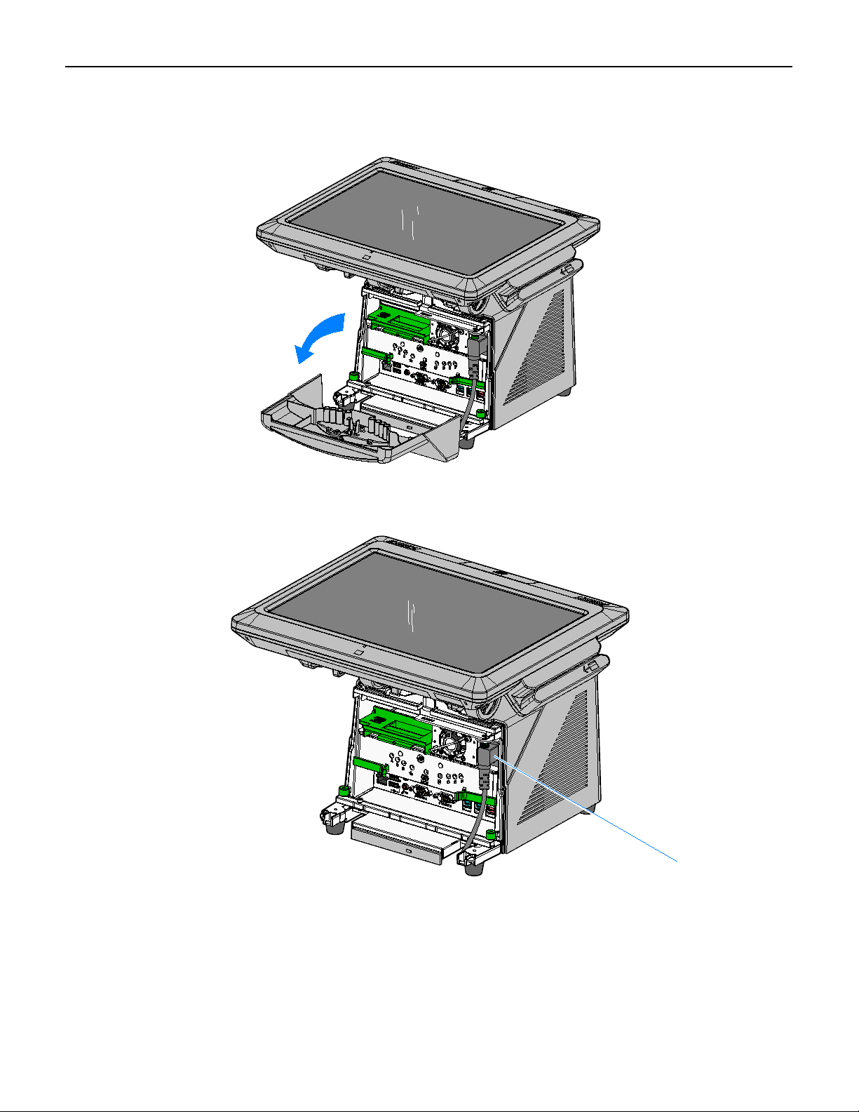
c. Pivot the top of the Front Base Cover toward the front of the unit and remove it from
26032
26135
AC Power Cord
the terminal.
3
d. Disconnect the Power Cord from the Power Supply.
Page 6
4
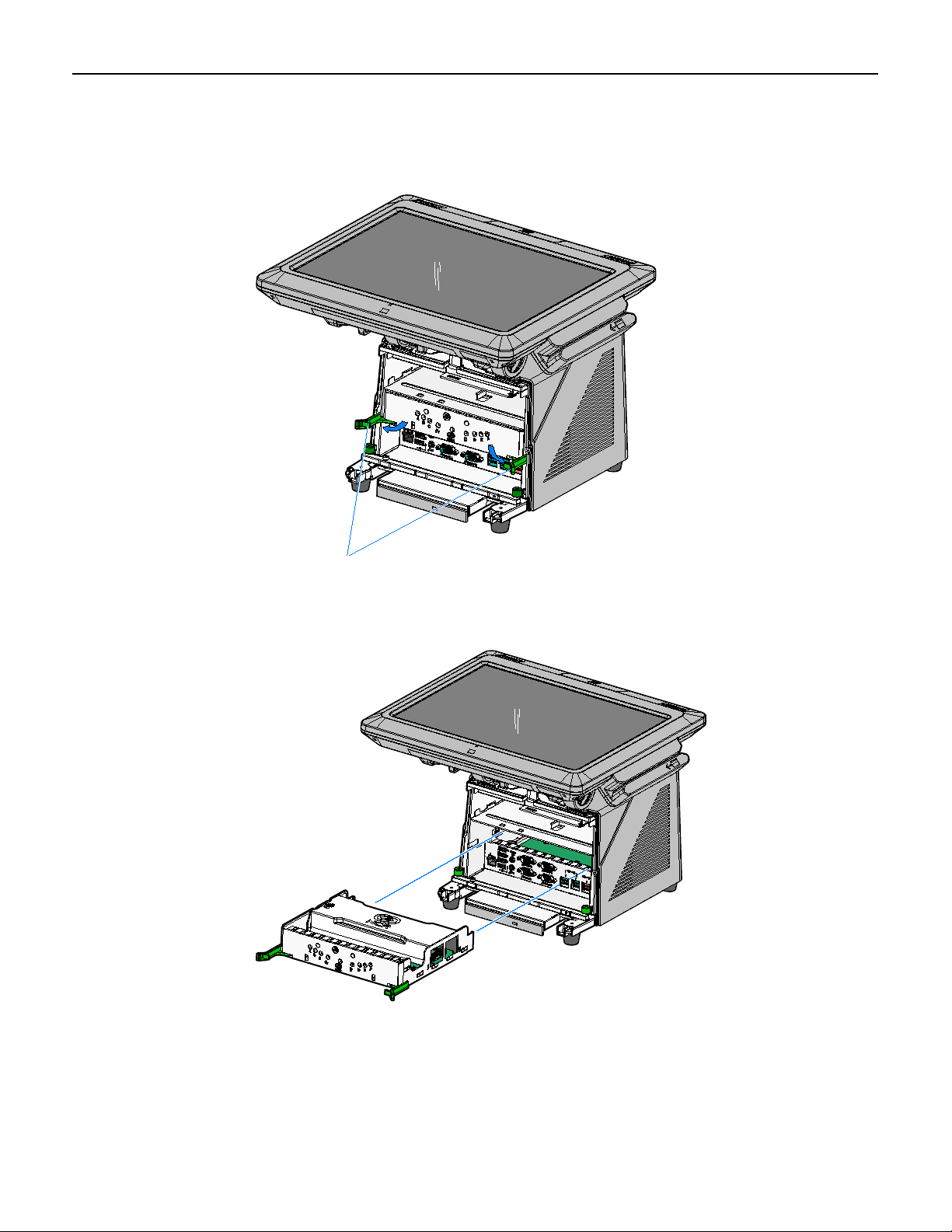
26038
Motherboard Sled Latches
26039
2. Disengage the Motherboard Sled Latches (2) that secure the assembly to the
chassis by pivoting them outwards as shown. This action disconnects it from the
Backplane Board.
3. Grasp the front of the Motherboard bracket and pull the assembly out of the
chassis.
Page 7

4. Remove the memory module(s). Open the latches at the ends of the socket to
26277a
Memory Module
Latches
release each module.
5
Page 8

6
29505
5. Install the new memory module(s).
The Motherboard contains two memory module sockets, stacked one on top of the
other. The sockets can be populated with any combination of the supported
memory module sizes (512MB, 1GB, 2GB), with a maximum of 4GB total system
memory. If only one module is being used it should be installed in the bottom slot.
Note: The Intel ME/AMT features will not function unless the bottom slot is
populated.
a. Align the new module in the socket and push it into the socket (note the socket is
keyed).
b. Press the edge of the module down until it latches in position. Ensure that the
ends of the module engage the latches and that the latches are completely
closed.
6. Install the Motherboard Sled into the Base of the 7403.
7. Install the Front Base Cover and lock the Security Lock.
Page 9

SelfServ 60 (7409) Installation Procedures
26650
Captive Screws
Rear Cover
1. Lay the terminal face down on a flat surface.
2. Loosen the captive screws (2) that secure the Rear Cover.
7
Page 10

8
26651
Rear Cover Latches
3. Pivot the Rear Cover to the open position.
4. Remove the Rear cover by squeezing the Rear Cover Latches together as indicated
above.
Page 11

1. Remove the memory module(s). Open the latches at the ends of the socket to
29506
Latches
release each module.
The Motherboard contains two memory module sockets, stacked one on top of the
other. The sockets can be populated with any combination of the supported
memory module sizes (512MB, 1GB, 2GB), with a maximum of 4GB total system
memory. Note the memory configuration and replace them in the new board in
the same configuration.
Note: The Intel ME/AMT features will not function unless the bottom slot is
populated.
9
Page 12

10
29505
2. Install the new memory module(s).
Note: If only one memory module is being used insert it in the bottom socket.
The Intel ME/AMT features will not function unless the bottom slot is populated.
a. Align the new module in the socket and push it into the socket (note the socket
is keyed).
b. Press the edge of the module down until it latches in position. Ensure that the
ends of the module engage the latches and that the latches are completely
closed.
Page 13

RealPOS 40 (7600) Installation Procedures
28700
Memory Module
Socket Latches
Warning: Disconnect the AC power cord before disassembling the Terminal.
Caution: Static Electricity Discharge may permanently damage your system.
Discharge any static electricity build up in your body by touching your computer’s
case for a few seconds. Avoid any contact with internal parts and handle cards only
by their external edges.
1. Turn Off the power to the terminal and any connected peripheral devices. Unplug
the terminal’s power cord.
2. Remove power from the terminal.
3. Open the Top Cover.
4. Open the latches at the ends of the memory socket as shown below to release the
module.
11
5. Remove the memory module.
Page 14

12
29507
6. Align the new module in the socket and push it into the socket (note the socket is
keyed).
7. Press the edge of the module down until it latches in position. Ensure that the
ends of the module engage the latches and that the latches are completely closed.
Page 15

RealPOS 25 (7610) Installation Procedures
29258
Captive Screws
Warning: Disconnect the AC power cord before disassembling the Terminal.
Caution: Static Electricity Discharge may permanently damage your system.
Discharge any static electricity build up in your body by touching your computer’s
case for a few seconds. Avoid any contact with internal parts and handle cards only
by their external edges.
1. Turn Off the power to the terminal and any connected peripheral devices. Unplug
the terminal’s power cord.
2. Remove power from the terminal.
3. Remove the Rear Cover (loosen the captive screws (4) that secure it to the chassis.)
13
Page 16

14
29272
SODIMM
Socket Latches
4. Open the latches at the ends of the memory socket as shown below to release the
module.
5. Remove the memory module.
Page 17

6. Align the new module in the socket and push it into the socket (note the socket is
29507
keyed).
15
7. Press the edge of the module down until it latches in position. Ensure that the
ends of the module engage the latches and that the latches are completely closed.
 Loading...