

Page 1
7403-K300
26309
NCR RealPOS 70XRT (7403)
GMS Integration Tray
Kit Instructions
Issue A
Page 2

Page 3

Date Remarks
A
Nov 2008
First issue
Revision Record
Issue
Page 4

Page 5
1
26323
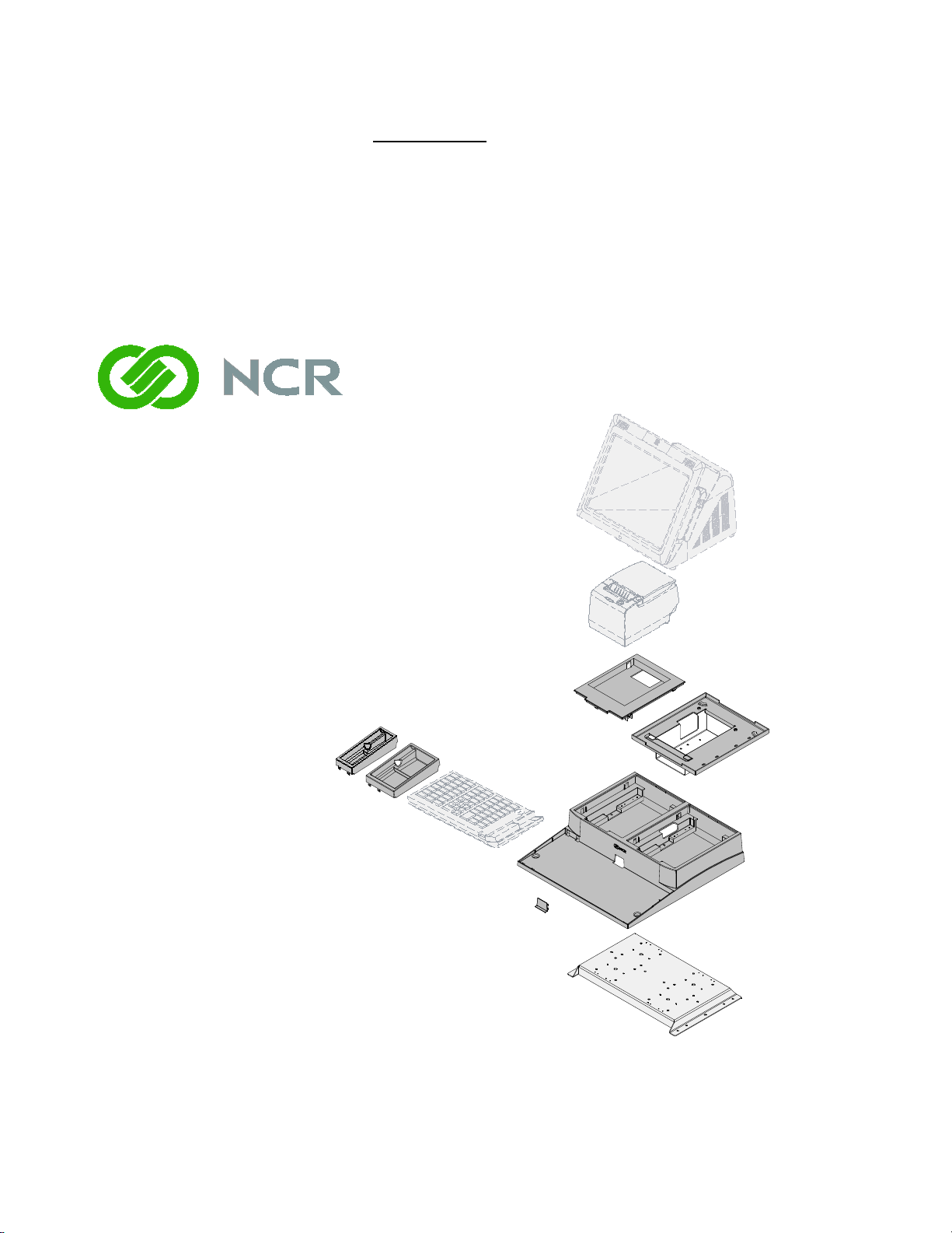
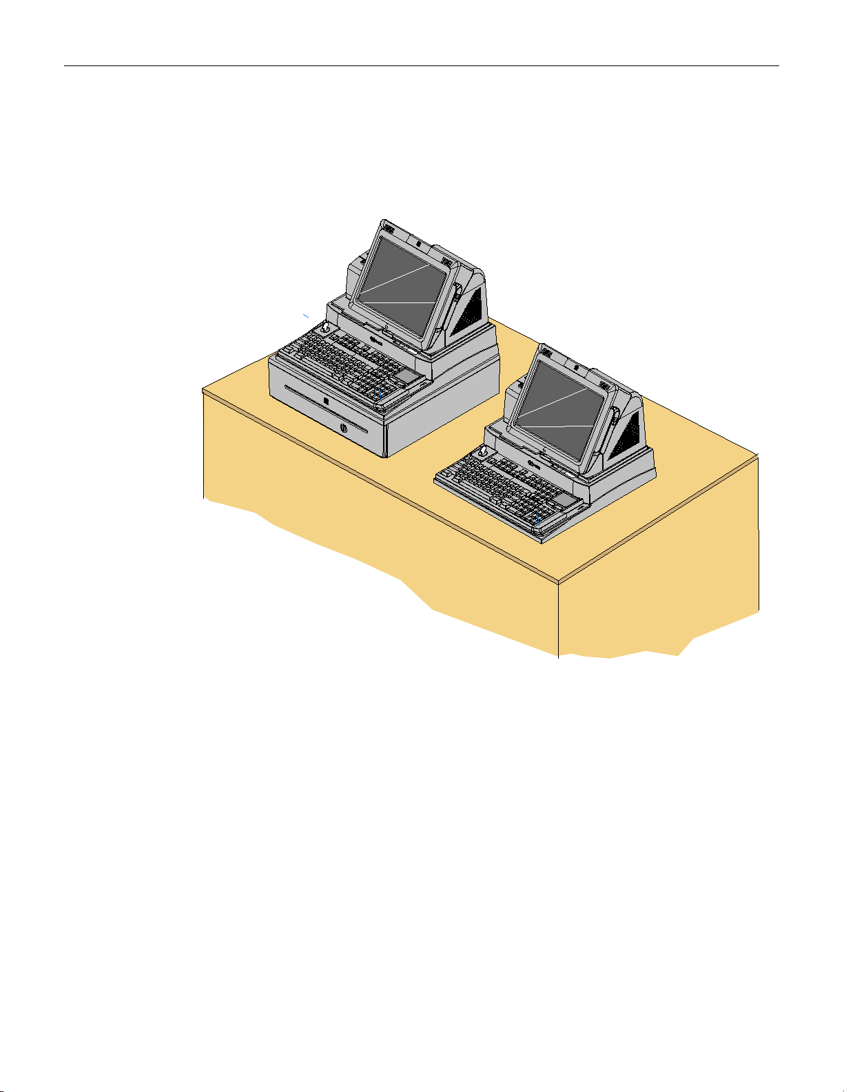
Introduction
The Peripheral Integration Tray kit provides the necessary components for integrating
a printer and keyboard with the RealPOS 70
XRT or RealPOS 72 XRT terminal. It can be
mounted on a flat surface or on a cash drawer.
Page 6
2
26313
Integration Tray
497-0451781 (CG1)
Tray Support Bracket
497-0451821
Integration Tray Plug
497-0459016 (CG1)
7403 Integration Tray Adapter
497-0460475
7459 Printer Skirt
497-0451793 (CG1)
7459 Compact A lpha Filler
497-0451848 (CG1)
Screw, 8-32 x 0,375,
PH, Phillips
006-8611339
Compact Alpha w/MSR Filler
497-0451797 (CG1)
Components
Page 7
3
26314
Installation Procedures
The Integration Tray can be installed on an NCR 2181 Cash Drawer or it can be
installed directly to a flat surface. The installation procedures are identical except for
including the cash drawer.
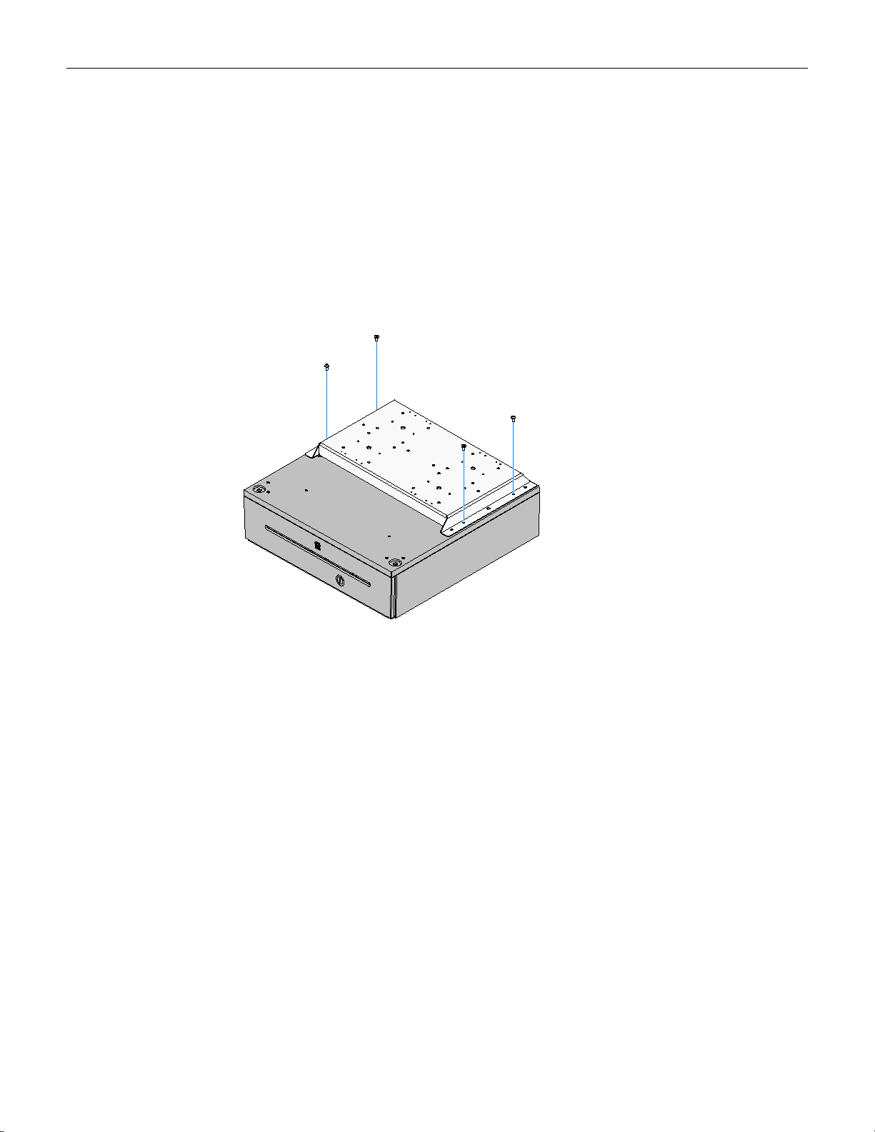
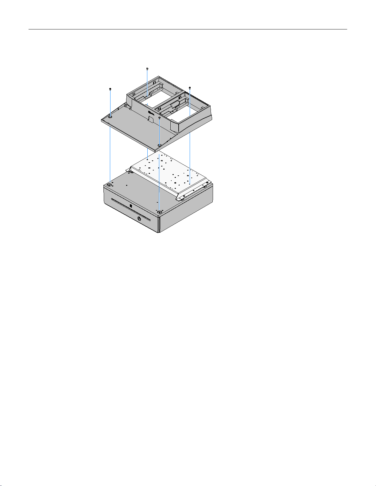
Installing on a Cash Drawer
1. Position the Tray Support Bracket on a Cash Drawer using the supplied screws
(4).
Page 8
4
26315
2. Position the Integration Tray on top of the Tray Support Bracket and secure it with
screws (4).
Page 9
5
24611
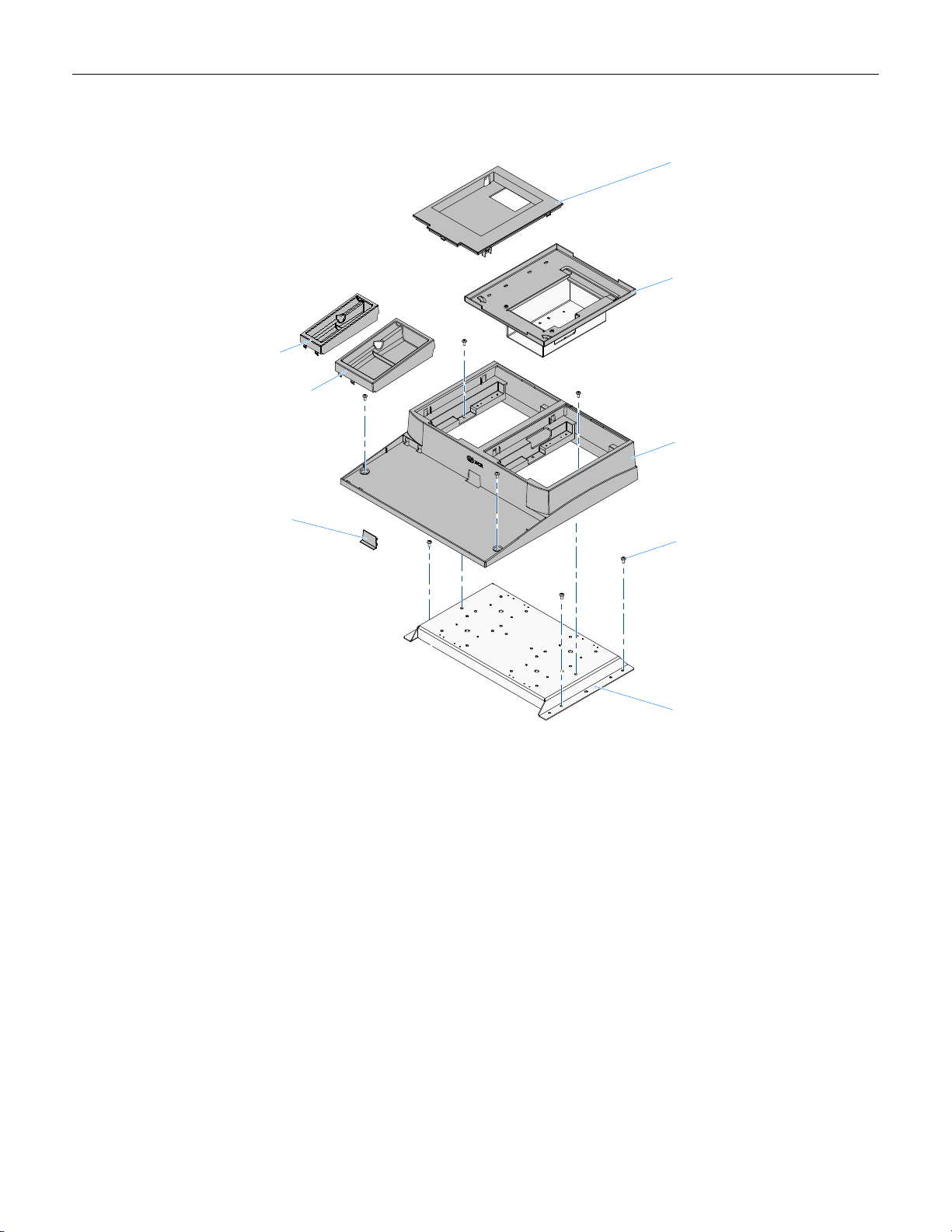
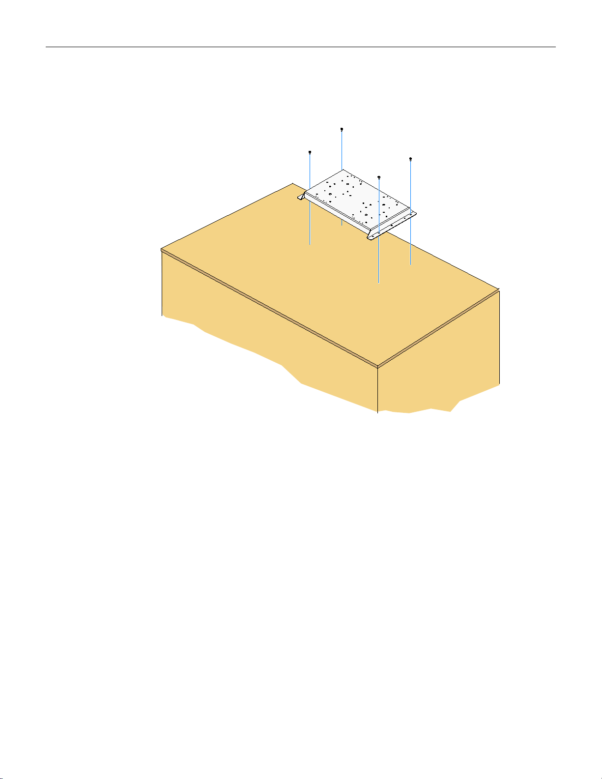
Installing on a Flat Surface
1. Position the Tray Support Bracket on mounting surface and secure it with screws
(4) that are appropriate for the surface type.
Page 10

6
24613
2. Position the Integration Tray on top of the Tray Support Bracket. Secure the tray to
the Tray Support Bracket with screws (2). Secure the front of the tray to the
mounting surface with screws (2) that are appropriate for the surface type.
Page 11

7
26316
NCR 5932-5xxx USB Alphanumeric
Big ticket Keyboard
Installing the Keyboard
Note: If a keyboard is not used insert the Integration Tray Plug into the opening
where the keyboard cable would normally be routed.
1. Install the keyboard in the Integration Tray.
2. Route the cable as shown.
Page 12

8
26317
Wide Insert - Use with 5932-6xxx Compact Keyboard w/o MSR
Narrow Insert - Use with 5932-6xxx Compact Keyboard w/MSR
5932-22xx 64-Key POS Keyboard
5932-65xx PS/2 Compact Alpha-Numeric
Keyboard (not shown)
or
Compact Keyboard: Install the Keyboard Tray Insert beside the keyboard.
Note: There are two Keyboard Tray Inserts. The narrow tray is used in all cases
except when using the 5932-65xx PS/2 model without an MSR.
Page 13

9
Cable Strain Relief
26318a
7167/68 Release 1.0 Printer
7167/68 Series II Printer
Do not remove the Cable Strain Relief
on Series II printers.
Installing the Transaction Pr inter
The NCR 7167, 7168, 7197, or 7198 printer can be located on either side of the
Integration Tray.
Note: The Printer Cable Strain Relief is different on the Release 1.0 and the Series II
printers. The Cable Strain Relief on Release 1.0 printers prevents the printer from
sitting properly in the Integration Tray and must be removed from the printer and
installed in the Integration Tray.
NCR 7167/7168 Release 1.0 Printers Only:
1. Remove the Cable Strain Relief from the back of the printer (2 screws). The printer
will not sit properly in the tray with it installed.
2. Install the Cable Strain Relief on the Integration Tray using the same screws.
Page 14

10
33279a
3. Connect the Printer Cable to the USB and Power connectors.
4. Series II Printers Only: Route the cable through the Cable Strain Relief on the
printer as shown.
Page 15

11
26319a
7459-K316 Printer Skirt
7197/7198 Printer
7167/7168 Printer
Release 1.0
To Printer
To Host
5. Route the printer cable(s) through the openings in the Integration Tray as shown
below and set the printer in the tray opening.
NCR 7197/7198 Only: Install the 7459-K316 Printer Skirt (included with 7403-K300).
NCR 7167/7168 Only: Secure the cable in the Cable Strain Relief as shown.
Page 16

12
26320
Installing the Terminal
1. Install the 7403 Integration Tray Adapter. It can be located on either side of the
tray. Consideration should be given to the total integrated terminal configuration
to obtain satisfactory clearances. Secure the adapter to the Tray Support Bracket
with screws (4).
Page 17

13
26321
2. Place the 7403 terminal on the 7403 Integration Tray Adapter.
Page 18

14
26031
26124
Security Key
Front Cover
Connecting the External Cables to the Terminal
1. Tilt the Display Module.
2. Remove the Front Cover.
a. Insert the Security Key and turn it 90 degrees clockwise.
Page 19

15
26032
b. Pivot the top of the Front Cover toward the front of the unit and remove it
from the terminal.
Page 20

16
26297a
Line Out
RS232/D
RS232/C
RS232/B
RS232/A
MIC
A
B
C
D
12V
24V
Cash
Drawer
LAN
E
F
G
Connector I/O Panel
1. Connect the printer and LAN cables to the I/O panel.
Page 21

17
Line Out
RS232/DRS232/C
RS232/BRS232/A
MIC
A
B
C
D
12V 24V
Cash
Drawer
LAN
E F G
26324
24V USB
Power
USB
497-0441177 - 1 m
(1432-C088-0010)
497-0441178 - 4 m
(1432-C088-0040)
Printer Cable Connections
The printers can connect through a USB connector or an RS-232 connector. It receives
power through a Powered USB power cable.
USB Installation
Connect the Powered USB Printer Interface Cable to the USB Connector and Power
Connector on the printer and to the 24 V Powered USB Connector on the terminal.
Page 22

18
Line Out
RS232/DRS232/C
RS232/BRS232/A
MIC
A
B
C
D
12V 24V
Cash
Drawer
LAN
E F G
26325
Power
RS-232
24V USB
RS-232A/B (Set to Non-Powered)
9-Pin to 9-Pin (Beige)
497-0408349 - 0.7 m
(1416-C359-0007)
9-Pin to 25-Pin (7162)
497-0407427 - 1.0 m
(1416-C337-0010)
497-0407429 - 4 m
(1416-C337-0040)
497-0407430 - 15.2 m
(1416-C337-0152)
9-Pin to 9-Pin (Black)
497-0430266 - 1.0 m
(1416-C879-0010)
497-0430265 - 4 m
(1416-C879-0040)
497-0441156 - 1m
(1432-C092-0010)
497-0441157 - 4 m
(1432-C092-0040)
RS-232 Installation w/Power from Powered USB
1. Connect the RS-232 Printer Interface Cable to the RS-232 Connector on the printer
and to an RS-232 Connector on the terminal.
2. Connect the Printer Power Cable to the Power Connector on the printer and to the
24 V Powered USB Connector on the terminal.
Page 23

19
Line Out
RS232/DRS232/C
RS232/BRS232/A
MIC
A
B
C
D
12V 14V
Cash
Drawer
LAN
E F G
26327
Cash Drawer Connectors
Cash Drawer Cable Connections
The Cash Drawer can be installed remotely or integrated with the terminal. It can be
connected to the Cash Drawer connector on the terminal or to the transaction printer
Cash Drawer Kickout.
Page 24

20
Line Out
RS232/D
RS232/C
RS232/B
RS232/A
MIC
A
B
C
D
12V
14V
Cash
Drawer
LAN
E
F
G
26326
Cash Drawer Connectors
Second Cash Drawer Cable Connection
The terminal supports a 2-drawer configuration with a Y-cable (1416-C372-0006).
Connect the Y-cable to the terminal or transaction printer cash drawer connector.
Page 25

21
26135
AC Power Cord
AC Power Cord Connection
1. Attach the Power Cord to the system and to an AC power source.
Page 26

22
26122
Cable Guide
Cable Routing
The cables are routed under the base and out the rear of the unit. There are two ways
to secure the cables.
Terminal Configured wit h a DVD -ROM Drive
If configured with a DVD the cables are routed in the two channels in the bottom of
the Base. There are pivoting latches that keep the cables secured in the channels.
Page 27

23
26236
Cable Clamp Thumbscrew
Terminal without a DVD-ROM Drive
If there is no DVD present then there is an additional Cable Clamp on the front of the
Base chassis that is used to secure the cables.
1. Loosen the Cable Clamp Thumbscrew
2. Pivot the clamp away from the terminal.
3. Route the cable between the clamp and base.
4. Secure the Cable Clamp Thumbscrew.
Page 28

24
26328
External Cable Routing
The cables are routed out the back of the terminal and down through the Integration
Tray and cash drawer, if applicable.
 Loading...