

Page 1
NCR EasyPoint 7401
Release 2.5
Hardware User's Guide
N
R
C
B005-0000-1254
Issue H
19797
Page 2

The prod uct s d es cr ibed in thi s b ook are licensed products of N C R Corporation.
MicroTouch is a re gi st e red t rad emark of Micr oT o uch .
NCR and EasyPoint are regist ere d t rademarks of NCR Corporati on.
Novell and Netware are registe red trademarks of Novell, Inc.
Pentium is a registered trademark of Intel Corporation.
Power Mon II is a registered trade mar k of Systems Enhancement Corp oration.
Sound Blaster is a registered t rad emark of Creative Technol ogy, L t d.
SoundFusion is a registere d t rademark of Cirrus Logic, Inc.
Microsoft, Windows, and Windows NT are registered trad emarks of Microsoft Corporation.
Symantic and Ghost are registered trademarks of Symantec Corporation in the United States and other
countries.
It is the policy of NCR Corporation (NCR) to improve products as new technology, components, software,
and firmware become available. NCR, therefore, reserves the right to change specifications without prior
notice.
All features, functions, and o perat ions described herein may not be marketed by NCR in all pa rts of the
world. In some instances , photograph s a re of equipment prototypes. Ther efore, befor e using this d ocument,
consult with your NCR representative or NCR office for information that is applicable and current.
To maintain the quality of our publications, we need your comments on the accuracy, clarity, organization,
and value of this book.
Address correspondence to:
Manager, Information P roducts
NCR Corporation
2651 Satellite Blvd.
Duluth, GA 30096
Copyright © 2002
By NCR Corporati on
Dayton , Ohio U. S.A.
All Rights Reserved
Page 3

Safety Warnings
i
Preface
Audience
This book is writt en for h ard ware installer/service p e rs onn el, system
integrators, and field engineers.
Notice: This do cume n t is NCR p roprie ta ry information and is n o t to
be disclosed or reproduced without consent.
Servicing
Caution: This product does not contain user serviceable parts.
Servicing s hould only be perform e d by a qu a lifie d service technicia n .
Fuse Replacement
Caution: For continued protection against risk of fire, replace only
with the same type and ratings of fuse.
Attention: Pour prévenir et vous protéger contre un risque de feu,
remplacer la fusible avec une autre fusible de même type, seulement.
Power Supply Cord Used as Disconnect Means
Caution: The power supply cord is used as the main disconnect
device. Ens u re tha t the socket outlet is loca te d / ins ta lle d near the
equipment and is easily a cce ssible.
Attention: Le cordon d'a lim e n t at ion est utilisé comme inte rrupt e u r
général. La pris e de co u ra n t doit êt re situé e ou inst a llée å prox imité du
matériel et être facile d'accés.
Lithiu m Battery Warning
Caution: Danger of exp losion if battery is in corre ct ly repla ced .
Replace only with the same or equivalent type as recommended by the
manufacturer. Discard used batteries according to the manufacturer's
instructions.
Page 4

ii
Attention: Il y a danger d' explosion s' il y a rempla ce m e n t inco rrect d e
la batterie. Remplacer uniquement avec une batterie du même type ou
d'un type recommandé par le constructeur. Mettre au rébut les
batteries us a g é es co n formé m e nt aux ins t ru ct ions du fabrica n t .
Battery D isposal (Switzerl a n d )
Refer to Annex 4.10 of SR814.013 for battery disposal.
IT Power System
This product is su it able for co n n e ct ion t o an IT powe r sys t em wit h a
phase-to-phase voltage not exceeding 240 V.
Periphera l Usage
This terminal should only be used with peripheral devices that are
certified by th e ap p ro p ria t e sa fety agency for the country of ins t a llat io n
(UL, CSA, TUV, VDE) or those which are recommended by NCR
Corporation.
Caution: DO NOT connect or disconnect a printer, keyboard, or any
other terminal-powered peripheral while the terminal is powered on.
Doing so may res u lt in peripheral or system damage.
System Weight Considerations
Warning: The NCR 7401-1xxx and 7401-2xxx terminals must be
mounted securely to prevent a hazard. They must be installed in
accordance with lo ca l building codes. The post or wall on which the
unit is mounted should be able to withstand four tim es the weight of
the unit, which is approximately 20 lbs. (9 kg). The NCR 7401-4xxx is
a desk-top unit that has an assembled weig ht of approximately 90
lbs. (40.8 kg).
Environmental Consciousness
NCR is demonstrating its concern for the environment by designing an
intelligen t p o we r man ag eme n t sys t em in t o th is te rminal that operates
efficiently whether the system is in a stand-alone or network
environment.
Page 5

Grounding Instructions
In the event of a malfunction or breakdown, grounding provides a
path of least resistance for electric current to reduce the risk of electric
shock. This product is equipped with an electric cord having an
equipment-grounding conductor and a grounding plug. The plug must
be plugge d into a matching outle t t hat is properly inst a lle d a n d
ground ed in a cco rda n ce wit h all loca l co de s and ordinan ce s. D o not
modify th e plug p ro vid e d – if it will n o t fit the outle t , h a v e the pr ope r
outlet installed by a qualified e le ct rician. Im proper conn e ctio n of t h e
equipm ent -grounding con ductor can result in a risk o f electr ic s hock.
The conductor with insulation having an outer surface that is green
with or without yellow stripes is the equipment-grounding conductor.
If repair or replacement of the electric cord or plug is necessary, do not
connect the equipment-grounding conductor to a live terminal. Check
with a qualified e lect rician or se rvice p e rsonnel if the groun ding
instruct io n s ar e not co mp le t e ly un d ers to o d, o r if in do u bt as t o whe the r
the product is properly grounded.
Use only 3-wire extension cords that have 3-prong grounding plugs
and 3-pole receptacles that accept the product’s plug. Repair or replace
damaged or worn cords immediately.
iii
References
• NCR EasyPoint 7401 Hardware Service Guide (B005-0000-1341)
• NCR EasyPoint 7401 Site Preparation Guide (B005-0000-1255)
• NCR EasyPoint 7401 Interface Guide (B005-0000-01405)
• NCR EasyPoint 7401 ATX 38 Printer User’s Manual
(B005-0000-1454)
• NCR EasyPoint 7401/7454 Retail Terminal Parts Identification Manual
(B005-0000-1072)
• NCR FitClient Software User's Guide (B005-0000-1235)
• NCR EasyPoint 7401 Migration Guide (B005-0000-1500)
• NCR Retail Platform Software Terminal Utilities Guide
(B005-0000-1503)
Page 6

iv
Table of Contents
Chapter 1: 7401-2xxx and 3xxx Product Overview
Introduction.................................................................. 1-1
Serial Number/Model Number Label........................ 1-2
Fixed-Angle Mount Label......................................1-2
Tilt-Mount Label ....................................................1-3
Hardware Modules......................................................1-4
Base Uni t.................................................................1- 4
Hardware Options.................................................1-5
Terminal Components not Supported..............1-7
System Co nfiguration Dia gr a m...................................1-8
Kit Configuration Diagram..........................................1-9
Hardware Module Descriptions................................ 1-10
Processor Board .................................................... 1-10
Processor/Chip Set.......................................... 1-10
Video Subsystem.............................................. 1-11
Ethernet 10/100Base-T LAN
Communications.............................................. 1-12
Wireless LAN Communications..................... 1-13
Universal Serial Bus......................................... 1-14
Serial Ports........................................................ 1-14
Hardware Monitor........................................... 1-15
PCI Expansion Header.................................... 1-15
IDE Header....................................................... 1-15
Audio................................................................ 1-16
Magnetic Stripe Reader ................................... 1-16
Touch Screen Controller.................................. 1-16
Processor Board Connectors ........................... 1-17
NCR Retail Specific Hardware........................ 1-18
Page 7

Board BIOS....................................................... 1-22
Operator Display.................................................. 1-26
LCD Adapter Board......................................... 1-26
LCD Backlight Inverter Module ..................... 1-26
Touch Screen.................................................... 1-27
Features....................................................................... 1-28
Magnetic Stripe Reader........................................ 1-28
Printer Options..................................................... 1-29
7401-K590 Self-Service Printer ........................ 1-29
7401-K580 Self-Service Printer
(Discontinued) .................................................. 1-30
7158 Printer....................................................... 1-31
7167 Printer....................................................... 1-31
7194 Printer....................................................... 1-32
7197 Printer....................................................... 1-32
Other Integrated Devices and Indicators........... 1-33
Hard Disk Drive............................................... 1-33
Reset Switch......................................................1-33
Internal Speaker............................................... 1-33
POS Connector Board...................................... 1-34
Motion Sensor.................................................. 1-34
Power/Status LED ........................................... 1-35
Power OK LED................................................. 1-35
LAN Status LEDs............................................. 1-35
Power Supply................................................... 1-36
Uninterruptible Power System (Optional) ..... 1-36
Integrated Scanner Module (Optional)...........1-36
Integrated Speaker Module (Optional) .......... 1-37
Compact Flash (Optional)............................... 1-37
USB RS-232 Port Server ................................... 1-37
Integrat ed CD -R OM Driv e (Tilt Mou n t
Model)............................................................... 1-38
v
Page 8

vi
Additional Connectors (Pentium III Board)....... 1-39
Compatibility.............................................................. 1-40
LAN Communications......................................... 1-40
Applicat ion Programmability ............................. 1-40
Operating System Information............................1-40
Migration.....................................................................1-41
Retail Applications............................................... 1-41
Retail Peripherals................................................. 1-41
Retail Systems....................................................... 1-42
Platform............................................................ 1-42
Networks .......................................................... 1-42
Platform Load...................................................1-42
Chapter 2: 7401-4xxx Product Overview
Introduction.................................................................. 2-1
Serial Number/Model Number Label........................ 2-2
Hardware Modules...................................................... 2-3
Base Uni t.................................................................2-3
Hardware Options................................................. 2-4
Terminal Components not Supported..............2-5
System Co nfiguration Dia gr a m...................................2-6
Hardware Module Descriptions.................................. 2-7
Processor Board ...................................................... 2-7
Processor/Chip Set............................................ 2-7
Video Subsystem................................................ 2-8
Ethernet 10/100Base-T LAN
Communications................................................ 2-8
Wireless LAN Communications....................... 2-9
Universal Serial Bus......................................... 2-10
Serial Ports........................................................ 2-11
Hardware Monitor........................................... 2-12
PCI Expansion Header.................................... 2-12
Page 9

IDE Header....................................................... 2-12
Audio................................................................ 2-12
Magnetic Stripe Reader ................................... 2-13
Touch Screen Controller.................................. 2-13
Processor Board Connectors ........................... 2-13
NCR Retail Specific Hardware........................ 2-14
Board BIOS....................................................... 2-17
Operator Display.................................................. 2-21
LCD Adapter Board......................................... 2-21
LCD Backlight Inverter Module ..................... 2-21
Touch Screen.................................................... 2-22
Features....................................................................... 2-23
Secure Cabinet with Integrated Speakers...........2-23
Ruggedized Keyboard with Trackball................ 2-23
Pin Pad .................................................................. 2-24
Motorized Card Reader....................................... 2-24
Magnetic Stripe Reader........................................ 2-25
Full Page Printer................................................... 2-25
Other Integrated Devices and Indicators........... 2-26
Hard Disk Drive............................................... 2-26
Integr a t e d CD-ROM ........................................ 2-26
Reset Switch......................................................2-26
Compact Flash.................................................. 2-27
Internal Speaker............................................... 2-27
POS Connector Board...................................... 2-27
USB Camera......................................................2-27
Motion Sensor.................................................. 2-28
Power/Status LED ........................................... 2-28
Power OK LED................................................. 2-29
LAN Status LEDs............................................. 2-29
Power Supply................................................... 2-29
vii
Page 10

viii
Motorized Card Reader Power Supply.......... 2-30
Full Page Printer Power Supply...................... 2-30
Integrated Speakers......................................... 2-30
EasyPoint 45 Pedestal...................................... 2-31
Chapter 3: 7401-2xxx and 3xxx Hardware Installation
Introduction.................................................................. 3-1
Installation Summary............................................. 3-1
Installation Restrictions................................................3-2
Connecting the Cables..................................................3-3
Fixed-Angle Mount (F504).....................................3-3
Fixed-Angle Mount (F503).....................................3-5
Cable Routing.....................................................3-7
Cable Connector Identification.........................3-9
Tilt Mount............................................................. 3-10
Cable Routing................................................... 3-11
Cable Connector Identification....................... 3-12
Installin g Peripherals ................................................. 3-13
Installin g a Tran sa ct ion Printer........................... 3-13
RS-232 Installation ........................................... 3-13
USB Installation................................................ 3-14
7401-K590 Self-Service Printer ........................ 3-15
Installin g a Cash Drawer ..................................... 3-16
Installin g a Second Cash Dra we r.................... 3-17
Installin g PC Card s .............................................. 3-18
Mounting a Fixed-Angle Mo un t Terminal............... 3-21
7401-K522 Pedestal Mount.................................. 3-22
7401-K521 Wall Mount ........................................ 3-23
7401-K521 Wall Mount with 7401-K530 Pole
Brackets................................................................. 3-25
Installing a K501 Tilt Mount Terminal ...................... 3-32
7401-K533 Wall Mount ........................................ 3-33
Page 11

Wall Mounting a 7401-K502 Core Module............... 3-34
7401-9212 LCD No-Cabinet (12.1-inch)..................... 3-36
Installation Guidelines......................................... 3-37
Mounting Specification Illustrations .................. 3-38
7401-9512 LCD No-Cabinet (15-inch)........................ 3-39
Installation Guidelines......................................... 3-39
Mounting Specification Illustrations .................. 3-40
4055 Uninterruptible Power System (UPS) .............. 3-42
Installin g the UPS................................................. 3-42
Installin g the Power Mon II Software.............. 3-43
Configu r ing t he P o wer M on II Software......... 3-43
Finalizing the Installation .......................................... 3-44
Completing the OS Installation (Win2000).... 3-44
Completing the OS Installation (WinXPe) ..... 3-44
Completing the OS Installation (WinNT).......3-45
Complet ing the OS Installation (W in 9 8 ) -
(Discontinued) .................................................. 3-45
Setting Auto-Logon (WinNT Terminal)....................3-47
Installin g a Seria l Mouse............................................ 3-52
Calibrating the Touch Screen .................................... 3-53
Calibration Using MicroTouch (Windows)........ 3-53
Calibration Using Microcal (DOS)...................... 3-55
Calibration From the BIOS.................................. 3-56
Summary .......................................................... 3-57
Out-of-Box Failures.............................................. 3-57
ix
Chapter 4: 7401-4xxx Hardware Installation
Introduction.................................................................. 4-1
Installation Summary............................................. 4-1
U.K. Keyboard Configuration...............................4-1
Windows 2000....................................................4-1
Page 12

x
Windows XPe..................................................... 4-2
Windows NT......................................................4-3
Installation Restrictions................................................4-4
Connecting the Cables..................................................4-5
Cable Routing.....................................................4-5
Cable Connector Identification.........................4-5
Installin g Peripherals ................................................... 4-6
Installin g the Angled Magn e t ic St ripe Reader
(MSR).......................................................................4-6
Installing Country Keyboards............................... 4-8
Using the Full Page Printer........................................ 4-13
Loading the Paper................................................ 4-13
Removing Paper from the Printer Feed Rolls.... 4-14
Removing Power from the Printer...................... 4-14
Using the Printer Test and Display Panel.......... 4-15
Display LED Indicators ................................... 4-15
Panel Switches .................................................. 4-16
Full Page Printer Diagnostics and Setup............ 4-17
Installing a 7401-4xxx on a Table Top Mount .......... 4-18
Mounting Proce dures.......................................... 4-18
Accessing the Mounting Screws..................... 4-19
Installing a 7401-4xxx on the EasyPoint 45 Pedestal 4-21
4055 Uninterruptible Power System (UPS) .............. 4-22
Installin g the UPS................................................. 4-22
Installin g the Power Mon II Software.............. 4-23
Configu r ing t he P o wer M on II Software......... 4-23
Finalizing the Installation .......................................... 4-24
Completing the OS Installation (Win2000).... 4-24
Completing the OS Installation (WinXPe) ..... 4-24
Completing the OS Installation (WinNT).......4-25
Complet ing the OS Installation (W in 9 8 ) -
(Discontinued) .................................................. 4-25
Page 13

Calibrating the Touch Screen .................................... 4-27
Calibration Using MicroTouch (Windows)........ 4-27
Calibration Using Microcal (DOS)...................... 4-29
Calibration from the BIOS................................... 4-30
Summary .......................................................... 4-31
Out-of-Box Failures.............................................. 4-31
Chapter 5: Setup
Introduction.................................................................. 5-1
Entering Setup without a Keyboard..................... 5-1
Entering Setup Using a Keyboard......................... 5-2
How to Select Menu Options ................................ 5-2
Setti n g t he Da t e a n d Ti me..................................... 5-3
Setting Passwords.................................................. 5-3
Configuring a Hard Drive.....................................5-4
Setti n g Me mo ry Cache...........................................5-4
Setti n g Me mo ry Shado w....................................... 5-5
Setting Boot Options.............................................. 5-5
Allocating Interrupts.............................................. 5-5
Restori n g Factor y Set t ings.....................................5-6
BIOS Default CMOS Values (7401-
22xx/35xx/45xx BIOS Version 2.2.1.x)................. 5-7
Main Values........................................................5-7
Advanced Values...............................................5-8
Security Values................................................. 5-13
Power Values....................................................5-13
Boot Values....................................................... 5-13
Exit Values........................................................ 5-14
Interrupts (7401-22xx/35xx/45xx BIOS
Version 2.2.1.x)..................................................... 5-14
Memory Map (7401-22xx/35xx/45xx BIOS
Version 2.2.1.x)..................................................... 5-16
xi
Page 14

xii
BIOS Default CMOS Values (7401-26xx/46xx
BIOS Version 2.3.x.x)............................................ 5-17
Main Values...................................................... 5-17
Advanced Values............................................. 5-18
Security Values................................................. 5-23
Power Values....................................................5-23
Boot Values....................................................... 5-23
Exit Values........................................................ 5-24
Interrupts (7401-26xx/46xx BIOS
Version 2.3.x.x)..................................................... 5-24
Memory Map (7401-26xx/46xx BIOS
Version 2.3.x.x)..................................................... 5-26
BIOS Default CMOS Values (7401-21xx/31xx
BIOS Version 1.5.0.4 - Discontinued).................. 5-27
Main Values...................................................... 5-27
Advanced Values............................................. 5-29
I/O Devi ce Configu r a t ion............................... 5-29
PCI Configuration............................................ 5-29
Interrupts (7401-21xx/31xx BIOS
Version 1.5.0.4 - Discontinued) ........................... 5-30
Memory Map (7401-21xx/31xx BIOS
Version 1.5.0.4 - Discontinued) ........................... 5-31
Chapter 6: Operating Syste m Re cov e ry
Introduction.................................................................. 6-1
Prerequisites ........................................................... 6-1
Updating Procedures.............................................6-3
Completing the OS Installation (Win2000)...... 6-5
Completing the OS Installation (WinXPe) ....... 6-5
Completing the OS Installation (WinNT).........6-6
Complet ing the OS Installation (W in 9 8 ) –
(Discontinued) .................................................... 6-6
Gold Disk Contents...................................................... 6-8
Page 15

Microsoft Operating System License
Agreements.............................................................6-8
Operating System Restrictions.............................. 6-9
Standby and Hibernate Mode Restriction........ 6-9
NCR 7401-22xx/25xx/32xx/35xx Win2000
Operating System Recovery Software (Version
02.03.00.01)..............................................................6-9
NCR 7401-26xx/46xx Win2000 Operating
System Recovery Software
(Version 02.05.00.02) ............................................. 6-11
NCR 7401-45xx Win2000 Operating System
Recovery Software (Version 02.04.00.02)............ 6-14
NCR 7401-22xx/25xx/32xx/35xx WinXPe
Operating System Recovery Software
(Version 02.05.00.01) ............................................. 6-16
NCR 7401-26xx/46xx WinXPe Operating
System Recovery Software
(Version 02.05.00.01) ............................................. 6-18
NCR 7401-/22xx/25xx/26xx/32xx/35xx NT
Operating System Recovery Software
(Version 02.05.00.02) ............................................. 6-20
NCR 7401-21xx/31xx NT Operating System
Recovery Software (Version 01.04.01.00)............. 6-22
NCR 7401-4xxx NT Operating System Recovery
Software (Version 02.05.00.02)............................. 6-24
NCR 7401-22xx/25xx/32xx/35xx Win98
Operating System Recovery Software
(Version 02.03.00.01) ............................................. 6-26
NCR 7401-21xx/31xx Win98 Operating System
Recovery Software (Version 01.01.00.00)............. 6-28
OS Recovery from a Larger Disk Image................... 6-29
xiii
Page 16

xiv
Chapter 7: BIOS Updating Procedures
Introduction.................................................................. 7-1
Prerequisites ........................................................... 7-1
Updating Procedures.............................................7-2
BIOS Crisis Recov e r y................................................... 7-5
Recove r y Pr ocedure s............................................. 7-6
Cable/Connector Pin-Out Information...................... 7-9
Chapter 8: NCR 7401/7890 or 7892 Scanner Differences
Introduction.................................................................. 8-1
Starting the 7401 Scanner Motor and Laser..........8-2
Programming the 7401 Scanner Using
Programming Tags.................................................8-3
Programming the 7401 Scanner Through the
RS-232 Interface...................................................... 8-4
7401 Scanner Default Settings ............................... 8-5
Appendix A: Cables
7401 Cables ............................................................ A-1
Appendix B: Feature Kits
7401 Kits..................................................................B-1
Index
Page 17

Revisi on Re cor d
Issue Date Remarks
A Aug 00 First issue (separated 7401 and 7454 sections out of
B005-0000-1069)
B Feb 01 Updated to Release 2.2
Removed hardware service informat ion from this
documen t which was previo us ly ca lled t h e 7401
Web Kiosk Har d war e Ins tal lation and Servic e Gui d e
(B005-0000-1254) and renamed it the 7401 Web Kiosk
Hardware User's Guide (B005-0000-1254). The
hardware service information wa s placed in a new
document, the 7401 Web Kiosk Hardware Se rvi c e
Guide (B005-0000-1341).
C June 01 Updated to Release 2.3
D Sept 01 Updated BIOS screens. Added PC Card
installation.
xv
E Dec 01 Additional updates for Release 2.3
F M ay 02 Updated to Release 2.4.
Changed Web Kiosk to EasyPoint 7401.
Added EasyPoint 7401-45xx terminal
F A ug 02 Add EasyP oint 45 Pedestal
G Sep 02 Add Country Keyboards to 7401-45xx
H Dec 02 Updated to Release 2.5
Added 7401-26xx and 7401-46xx models
Changed 7401-45xx references to 7401-4xxx
Page 18

xvi
Page 19
Radio Frequency Interference Statements
Federal Communications Commission (FCC)
Information to User
This equipment has been tested and found to comply with the limits for a Class A
digital device, pursuant to Part 15 of FCC Rules. These limits are designed to provide
reasonable protectio n against harmful interference when the equipment is operated in
a commercial environment. This equipment generates, uses, and can radiate radio
frequency energy and, if not installed and used in accordance with the instruction
manual, may cause harmful interference to radio communications. Operati on of this
equipment in a residential area is likely to cause interference in which case the user
will be required to correct the interference at his o wn expense.
NCR is not re sponsible for any radi o or t e l evision interference caus ed by unauthorized
modification of this equipment or the substitution or attachment of connecting cables
and equipment other than those specified by NCR. The correction of interference
caused by such unauthorized m odi fication, substitution or attach ment will be the
responsibility of the user. The user is cautio ned t hat changes or modifications not
expressly approved by NCR may void the user's authority to operate the equipment.
xvii
Canadian Department of Communication s
This Class A digital apparatus c omplies with Canadian ICES -003.
This digital apparatus does not exceed the Class A limits for radio noise emissions
from digital apparatus set out in the Radio Interference Regulations of the Canadian
Department of Co m muni cat ion s .
Cet appareil numérique de la classe A est confor me à la nor me NMB-003 du Canada.
Le présent appareil numérique n'émet pas de bruits radioélectriques dépassant les
limites applicables aux apparei ls nu mériques de la classe A prescrites dans le
règlement sur le brouillage radioélectriques édicté par le ministrère des
Communicatio ns du Canada.
Voluntary Control Council for Interference (VCCI)
Page 20

xviii
International Radio Frequen cy Interf erence Statement
Warning: This is a Class A p ro d uct. In a d o mestic environment this p roduct ma y
cause radio interference in which case the user may be required to take adequate
measures.
Page 21
IEC & EN Laser Product Label
xix
Laser Power
Class IIa Laser Product.
Avoid Long-term Viewing
of Direct Laser Light.
IEC & EN 60825-1 CLA S S 1 LA SER PRODUCT
Appareil à Laser de classe IIa
Eviter Toute Exposition Prolongèe
de la vue à la lumiè re laser directe.
CAUTION: Lase r
radiation when
open and interlock
defeated.
DO NOT STARE
INTO BEAM.
(Label is attached to laser
module inside the cabinet.)
Class IIa Producto Laser. Tratè
De no ver directamente èl Rayo
Laser por mucho tiempò.
This laser module
does not comply
wi th 21C FR1040.
USE O N LY A S A
Component.
17325
The NCR 7401 Scanner is not intended for long-term viewing of direct
laser ligh t. Ho wev e r, the unit is safe if used as int e nded. This scanner
meets the following laser/LED power re quire m e n ts.
• Class IIa CDRH (Center for Devices and Radiological Health)
• Class IIa Las e r—Avo id lo ng-t er m viewing of direct laser light
• Class 1 EN60-825 (Europäische Norm)
Following is the radiant energy of the las er/ L ED lig h t as app lie d t o
each of the specified requirements.
Accessible E m ission Limit (CD R H Calculation) 0.99 Milliwatt s
Accessible Emission Limit EN60 825-1:1994+AII:1996 0.81 Milliwatts
Caution: Use of controls or adjustments or performance of procedures
other than specified herein may result in hazardous radiation
exposure.
Page 22

xx
Declaration of Conformity
Manufacturer's Name
Manufacturer 's Address
NCR Corporation
NCR Corporation
Retail Solu t io n s Division – Atlan t a
2651 Satellite Boulevard
Duluth, GA 30096-5810
Type of Equipment
Model Number
Electrical Ratings (Input)
Informat io n Technology Equipment
Class 7401-2xxx and 7401-3xxx
100-120 V/200-240 V, 2.0 A/1.0 A, 50-60 Hz
NCR Corporation, 1700 South Patterson Boulevard, Dayton, OH 45459,
USA, declares that the equipment specified above conforms to the
referenced EU Directives and Harmonized Standards.
EU Directive Harmonized Standard(s)
89/336/EEC (EMC) EN 55022
EN 55024
EN61003-2
EN61003-3
73/23/EEC (Low Voltage) EN 60 950: A1 + A2 + A3 + A4 + All
NCR Corporation
Retail Solu t io n s Division — Atlan t a
2651 Satellite Boulevard
Duluth, GA 30096-5810
European Contact:
International IP Counsel
206 Marylebone Road
London, NW1 6LY, England
Page 23

Declaration of Conformity
xxi
Manufacturer’s Name
Manufacturer’s Ad dr ess
NCR Corporation
NCR Corporation
Retail Solu t io n s Division – Atlan t a
2651 Satellite Boulevard
Duluth, GA 30096-5810
Type of Equipment
Model Number
Electrical Ratings (Input)
Informat io n Technology Equipment
Class 7401-4xxx
100 - 240 V, 5.0 A, 50-60 Hz
NCR Corporation, 1700 South Patterson Boulevard, Dayton, OH 45459,
USA, declares that the equipment specified above conforms to the
referenced EU Directives and Harmonized Standards.
EU Directive Harmonized Standard(s)
89/336/EEC (EMC) EN 55022
EN 55024
EN61003-2
EN61003-3
73/23/EEC (Low Voltage) EN 60 950: A1 + A2 + A3 + A4 + All
NCR Corporation
Retail Solu t ions Division — Atlan ta
2651 Satellite Boulevard
Duluth, GA 30096-5810
European Contact:
International IP Counsel
206 Marylebone Road
London, NW1 6LY, England
Page 24

xxii
Page 25
Chapter 1: 7401-2xxx and 3xxx Product Overview
C
N
R
Introduction
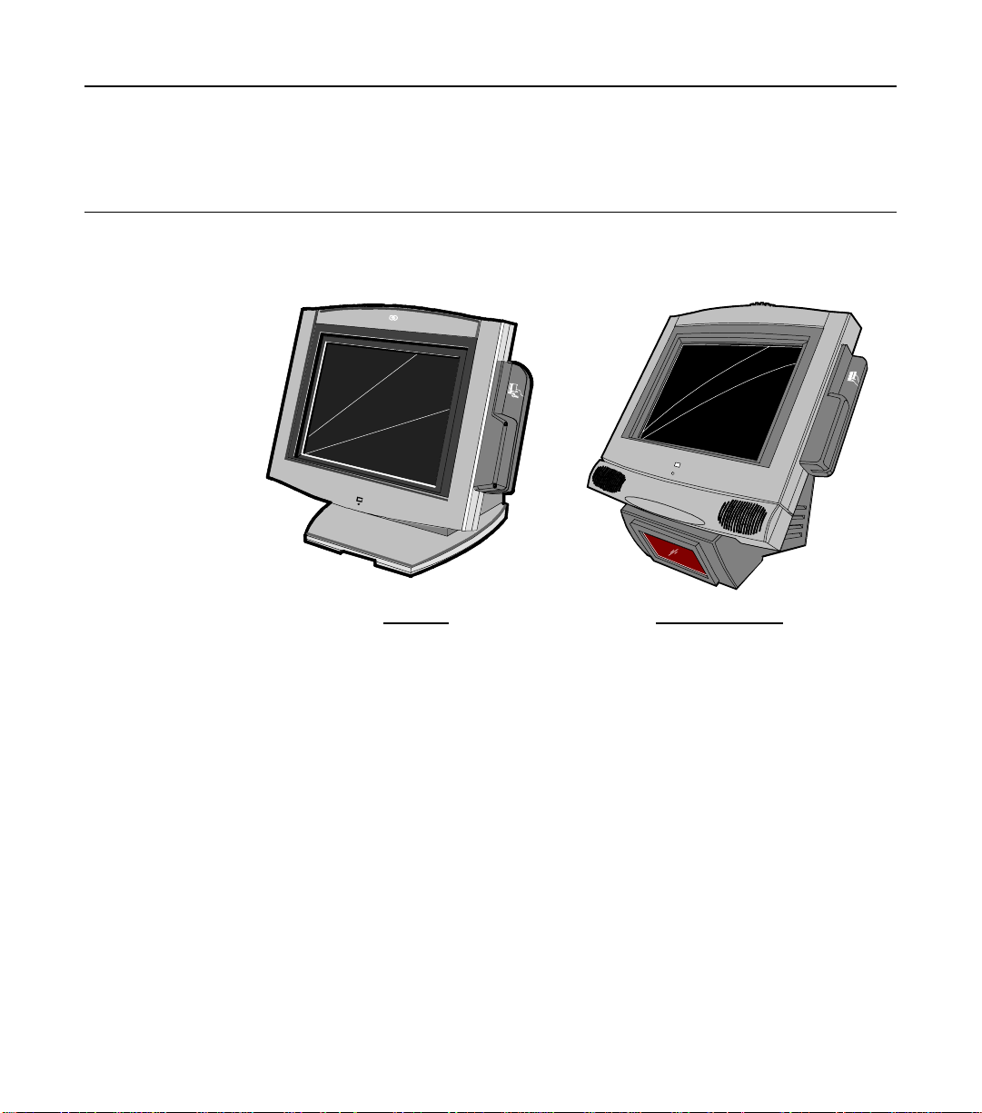
Tilt Mount Fixed-Angle Mount
18289
The NCR EasyPoin t 7 401 is an in te ra ctiv e to u ch screen t ermin a l wit h
retail functionality that supports a variety of kiosk and self-service
applications. The 7401 is housed in an integrated, compact cabinet and
can be tilt mounted, fixed-angle mounted or flush mounted.
The major hardware features of the 7401 are a 12.1-inch or 15-inch flat
panel display with touch screen input and LAN connectivity, plus
optional magnetic stripe reader, infrared reader, scanner, stereo audio,
self service printer and wireless LAN. It also supports custom kiosk
environments.
The 7401 is Internet/Intranet ready. System loading occurs from a
network server, and software and data content are delivered from a
server through standard Internet protocols.
Page 26
1-2 Chapter 1: 7401-2xxx and 3xxx Product Overview
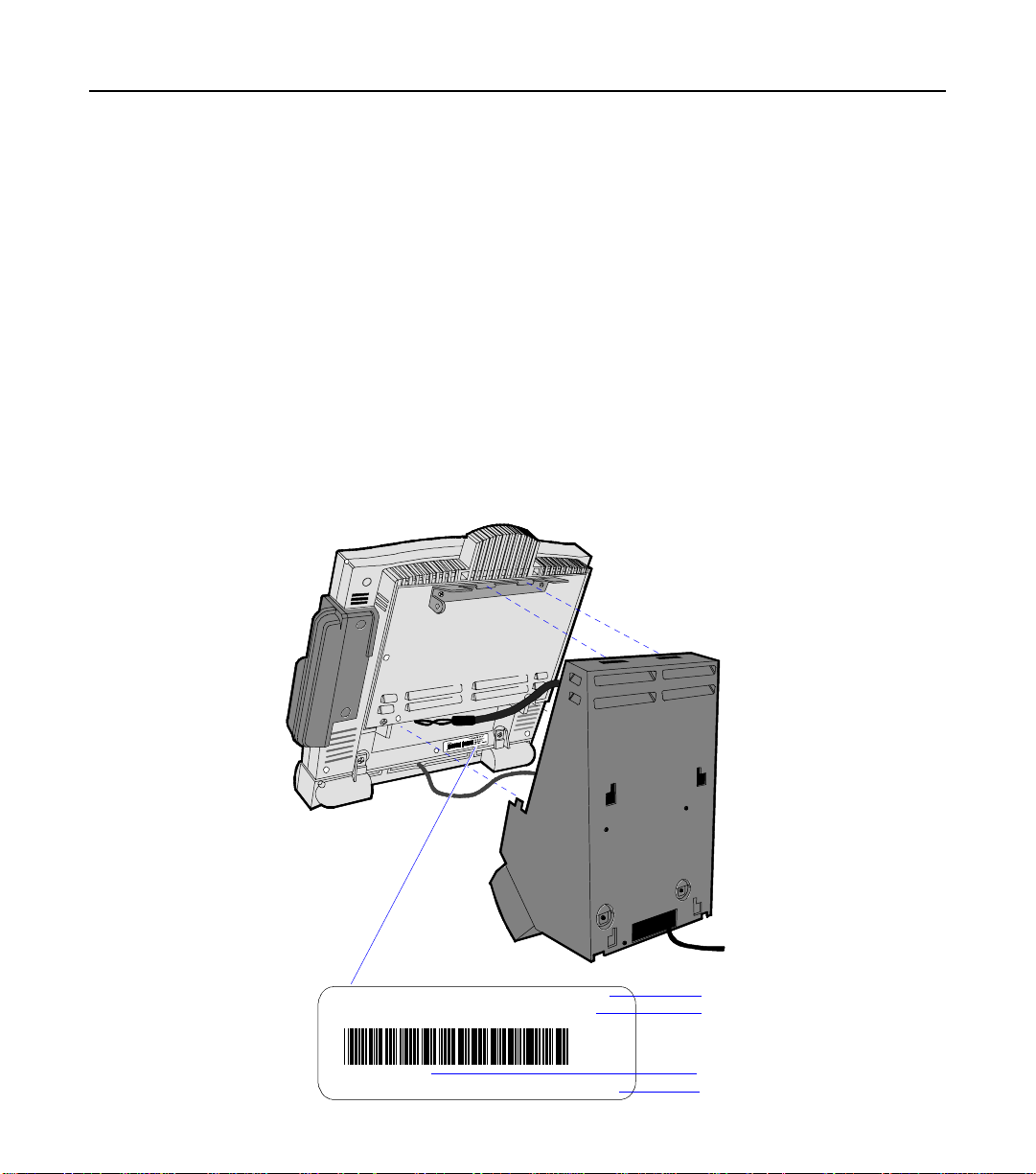
Serial Number/Model Number Label
The unit's serial number, model number, tracer number, and date of
manufa cture are include d on a label o n th e back o f the Core Mod u le.
Refer to following sections for additio n a l in form a t ion.
Note: The serial number is repeated on the non-MSR side of the Core
Module.
Fixed-Angle Mount Label
To view the label:
• For non-hinged mounts, remove the Core Module from the mount.
• For hinged mounts, the Core Module does not have to be removed.
NCR 7401-3000-8000
50-12345678
Date: 11/15/01
F000,F005,F024,F031,F050,F101,F200,F422,F503
Mfg
Class/Model
Serial Number
Date Ma nufacture d
Feature Number(s)
19476
Page 27
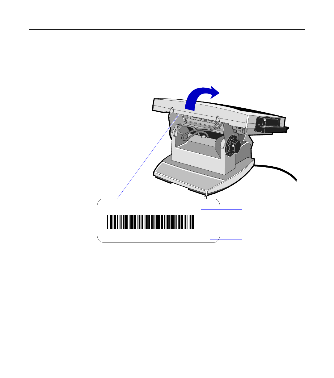
Tilt- M ount Label
Chapter 1: 7401-2xxx and 3xxx Product Overview 1-3
To view the label, tilt t h e Core M odule a n d rem ove the cable cov e r.
NCR 7401-2000-8000
50-12345678
Mfg
Date: 11/15/01
F000,F005,F024,F031,F050,F101,F200,F422,F503
Class/Model
Serial Number
Date Manufactured
Feature Number(s)
19477
Page 28

1-4 Chapter 1: 7401-2xxx and 3xxx Product Overview
Hardware Modules
Base Unit
• Processor Board
− Pentium III/Celeron processor
− SVGA chipse t (1 2-inch monitor)
− XGA chipse t (15-in ch monitor)
− MPEGII chipset
− 1 MB Flash BIOS (not CMOS)
− Four RS-232 ports (two optionally powered)
− 10/100BaseT Ethernet LAN chipset, Wake-on-LAN support,
and RJ-45 port
− PC Audio with an internal mono speaker
− SoundBlaster
− Two USB type A ports
− PS/2 keyboa r d po r t
− External VGA display port
− Dual d isplay suppo rt
− External stereo speaker port
− Internal PS/2 mouse (dedicated to the touch screen)
− One SODIMM (Sm a ll Ou t lin e DI MM ) RAM socket
− 64 MB memory on board
− IDE support for a hard disk, a CD ROM, and an optional
Compact Flash disk in place of the hard disk
16 compatible audio chipset
Page 29

Chapter 1: 7401-2xxx and 3xxx Product Overview 1-5
• POS Connector Board
− Cash drawer port (supports two drawers via a Y-cable)
− Internal parallel port (dedicated to the optional customer
display)
− Microphone
• 12.1-inch Operator Display – active capacitive touch LCD
• 15-inch Operator Display – active LCD with capacitive or resistive
touch
• 2.5-inch lo w or hig h capacity hard d isk
• Integrated Motion Sensor, capable of waking up the terminal from
a low power state
• Integrated Power Supply
• Reset swit ch which can be use d to recov er fro m a lock-up cond itio n
• 3-meter Ethernet cable
• U.S. power cord
Hardware Options
• Intel Pe nt ium III Pr o cessor
• Integrated 3-track ISO MSR
• Integrated Scanner Module
• Integrated Stereo Module
• Integra t e d CD-ROM
• Integr a t e d Infrared Sensor
• PCMCIA (for wireless LAN)
• Mounting opt ions: Table-top, Pedestal, P o le, Wall, Tilt / S wive l
• 256 MB Compact Flash
• 64/128/256 MB memory
Page 30

1-6 Chapter 1: 7401-2xxx and 3xxx Product Overview
• Cash drawers
− 2113 Cash Drawer (modular)
− 2189 Cash Drawer (modular)
− 2260 Cash Drawer (modular)
− Dual cash drawer cable
• Printers:
− 7158 Thermal Receipt/Impact Printer
− 7167 Thermal Receipt/Impact Printer
− 7194 Thermal Receipt Printer
− 7197 Thermal Receipt Printer
− Remote printer cables
− Signal extenders for remote printers
• 7401-K590 Self-Service Printer
• 7401-K580 Self-Service Printer (Discontinued)
• PC keyboard
− Keyboard Shelf
• USB RS-232 Port Server
− USB Serial Converter
• 4055 Uninterruptible Power System (UPS)
Page 31

Chapter 1: 7401-2xxx and 3xxx Product Overview 1-7
Terminal Components not Supported
It is important to note that the terminal does not support the following
components.
Not Supported Alternative Implementation
CMOS for hard totals, logs, and
tallies
Removable media, e.g., a flex
disk
Hard disk, flash disk, or server
storage
LAN commun ica tio n t o an NT server
via standard protocols
SLP terminal loading Local storage, TCP/IP networking
and PXE loading
Keylock for security (X, L, R, S) Reset switch based security
ISA and PCI Expansion slots USB and LAN based devices (future)
DVD ROM
Internal UPS External UPS
Manual Video and audio
Software controlled
controls
DOS, Windows 3.1, Windows
NT 3.51, Windows 9x, OS/2
133 MHz/266 MHz Pentium
Processor
Windows NT 4.0, Windows 2000,
Windows XPe
Intel Pentium III 500/700 MHz and 1
GHz , and Celeron 450/550/600/700
MHz proc e ssors
Page 32

1-8 Chapter 1: 7401-2xxx and 3xxx Product Overview
System Configuration Diagram
7401-K580/K590
7194
7892
7158
Note: 7194 and 7158 are
available in both RS-232
and USB.
7837
2010 Coin
Dispenser
2336-K008
RS232 (4)
2 Optionally
Powered
USB
POS Connector Bd.
Parallel
Cash Dwr
Processor Board
7401
Keyboard
PS/2 KBD
Audio
VGA
Ethernet
SVideo
2336-K007
2260/2189
2nd Cash Drawer
(Y-Cable)
2113
18319b
Page 33

Kit Configuration Diagram
7401 w/K590
2336-K037
2336-K052
Chapter 1: 7401-2xxx and 3xxx Product Overview 1-9
7401-3xxx
7401-2xxx
F504
F505
F511
F512
K523
F521
F201
K530
F200
F502
F101
K536
K535
F501
K542
K533
F/K059
K540
K543
F/K590
K525
K534
18318d-P
Page 34

1-10 Chapter 1: 7401-2xxx and 3xxx Product Overvi ew
Hardware Module Descriptions
Processor Board
Processor/Chip Set
The termin al uses an In te l a rch it e ctu re proce ssor, which permit s it to
leverage e x istin g s o ft ware dr iv ers and app lica t ion s, as well as provid e
the greate st flexibility in ch o osing an operatin g system. This pro vid e s
several other advantages:
• Capable of SW MPEG-1 or MPEG-2 playback at 30 frames per
second with 22 kHz stereo audio (may be limited by OS
constraints).
®
• SoundBlaster
• Expansion capa bilit ies for optiona l fe at u res and futu re
requirements (ISA/PCI bus and USB)
The following sections identify processors, system bus speed, and onboard memory available on 7401 processor boards:
-compatible audio
Release 1.0
• Intel Mobile Pentium 166 MHz or 266 MHz Processor (PGA
package) used with the Intel 430TX PC chipset. The 430TX chipset
consists of the 82439TX System Controller (North Bridge chip), also
called the MTXC, and the 82371A B (Sou t h B ridge ch ip), also called
the PIIX4.
• A 66 MHz system bus
Note: These Intel Mobile Pentium Processors have been
discontinued.
Page 35

Chapter 1: 7401-2xxx and 3xxx Product Overview 1-11
Release 2.0 – 2.4
• Intel Pentium III 500 MHz or 700 MHz Processor, or Intel Celeron
450 MHz, 550 MHz, or 600 MHz Processor (µPGA package) used
with the Intel 440BX PC chipset. The 440BX chipset consists of the
82440BX System Controller (North Bridge chip), also called the
MTXC, and the 82371AB (South Bridge chip), also called the PIIX4.
• A 100 MHz system bus
• 64 MB memory with a bilit y t o add S ODIMM S t o increa se the
memory capacity of the terminal
Release 2.5
• Intel 700 MHz Cele r o n P r o cessor or Int e l 1 GHz Penti um III
Processor (BGA package) on board, removing the µPGA processor
socket. Intel 440BX chipset same as in Release 2.0 – 2.5.
• 100 MHz system bus and memory support, 64-bit bus width, and
AGP video interface.
• 128 MB memory with ability to add SODIMMS to increase the
memory capacity of the terminal
Video Subsystem
The video subsystem supports the following LCD types:
• 12.1-inch active matrix (TFT [thin film transistor]) 800x600 with 64
k colors
• 15-inch active matrix (TFT) 1024x760 with 64 k colors
Support for the LCD in teg ra te d display is provided intern a lly. External
support for SVGA monitors (800x600 [or better] resolution and 64 k [or
better] colors ) is provided by a CRT 15-Pin D-s h e ll co n n e cto r.
The LCD back lig h t ing is a lso software controlled . In addition to OFF
and ON modes, a dimmed mode is supported in th e ha rdwa re to a llow
increased tube life. If appropriate software drivers are loaded, full
brightness is restored wh en t ouched, motion dete ct ion (Motion Sens or
section), or an application req u e st (i.e., to play prom ot io nal m a t eria l on
a preset schedule).
Page 36

1-12 Chapter 1: 7401-2xxx and 3xxx Product Overvi ew
Ethernet 10/100Base-T LAN Com m uni cations
The 7401 terminal has an Intel 82559 LAN Controller that supports
10/100Base-T Ethernet. Ethernet 100Base-T is also known as "Fast
Ethernet ." The Boot ROM for diskless bo ot funct ionality is inclu d e d in
the 1 MB system ROM. The hardware is compatible with the TCP/IP,
DHCP, and TFTP protocols required for remote boot of the platform.
Appropriate software must be used to enable each protocol used over
the Ethernet link.
The terminal may be connected to either a 10 MB/s or 100 MB/s
Etherne t conn e ct ion. The hardware a u t oma t ica lly selects t he cor re ct
speed (if enabled by soft wa re t o do so).
The LAN hardware supp o rts wake u p pack et capa bility as defined in
the Device C lass Power Managem ent Spe cifica tio n , Network Dev ice
Class (available from Microsoft's web site).
When the platform is in the Soft OFF state (refer to the Advanced Power
Management section that follows), rece ip t of a Wakeup Packet on the
LAN c an retur n the system t o t he ON s tat e, if this feature i s enabl ed by
software.
Note: Due to limitat ion s o f the L A N contro ller a n d the OS, all fe at u r es
described in t h e Netwo rk Device Class specification may not be
available.
100Base-T is wired identically to 10Base-T, except that the twisted pair
cable must be Category 5 and the hubs must permit 100 or 10/100
MB/s oper ation . A lt h oug h 10 Bas e-T will o p e ra t e on Cat e g o ry 3 twis t ed
pair, or NCR "747" cable, an upgrade to Category 5 is required for
100Base-T.
A customer desiring to use the terminal in an existing 10Base-T
environment can do so and simply run at 10 MB. In order t o upgrade t o
100MB/s, Category 5 cable and 100 or 10/100 hubs must be installed.
NCR strongly recommends the use of Category 5 for all new cabling,
even if the custo m e r initia lly intends to run on ly 1 0B ase -T.
Page 37

Chapter 1: 7401-2xxx and 3xxx Product Overview 1-13
LED Indicators for Link Integrity (verifies cable and hub connection are
good) and LAN speed is provided on the Processor Board near the row
of connectors at the bottom of the e-box. The LED is ON (yellow) when
the speed is running at 100 MB/s.
Link Integrit y is prov ide d to the PC chip set to permit boot-up s oft wa re
to verify the presence of the LAN connection. Software must allow 2
seconds after power-up in order for the Link Integrity signal to become
valid.
Wireless LAN Communi cati ons
When a wired Ethernet connection is not desired, a wireless LAN
adapter may be ins ta lle d in the PCMCIA socket. This requires that the
PCMCIA daugh t er -car d fe a t u re be installed. A wireless L A N us ed in
the terminal must meet the following requirements:
• Integrated antenna that meets the requirements of PCMCIA (PC
Card) Extended Type 2 card definition (a m aximu m of 5-cm
additional length).
• Power cons um ption wit h in the capabilities o f t h e PCMCI A
daughter-card.
• Signaling requirements with in t h e cap a bilitie s of the terminal
PCMCIA in terface . The main restriction is that DMA trans act io ns
are not supported over the PCMCIA interface.
• Device drivers for the targeted operating system must exist.
• Appropriate in frastructure (se rver supp ort , Base St a tio ns, Ceiling
Antennas, etc) must be present in the installation site, and the
maximum RF range of the wireless system must not be exceeded.
Interoperability - While the 802.11 standard provides an interoperable
protocol definition, there are vendor-specific extensions to the protocol
that encourage users to stay with one supplier's equipment. This also
applies to wireless infrastructure and access points, 802.11 does not
govern this o p e ra t ion. Mix ing of RF suppliers o n a site is n o t
recommen de d un til the RF supp liers have demonstra te d
interoperability.
Page 38

1-14 Chapter 1: 7401-2xxx and 3xxx Product Overvi ew
The wireless networks operate at speeds of 1-2 MB/s with 2 percent
packet loss t yp ica l. The application dev e loper must be aware of the
performance limitations and design applications that are acceptable to
the customer when run over the slower network.
Remote Wakeup over the wireless network is n ot p ossible be cause the
cards do not support it. An alternative is to use the system real-time
clock wake up at a scheduled time.
The wired Ethe rn et con n ect ion is not cert ified for us e in configurations
where a wireless a dap te r is inst a lled .
Universal Serial Bus
Two USB Type-A ports are provided on the terminal. USB Host
Controller support is provided in hardware on the Processor Board.
Note: Third party USB peripherals require support from the operating
system, which is currently limite d to Win d ows 2 000 and W in do ws
Xpe. The terminal must use the I/O Networks drivers to support the
NCR USB printer and scanner products. These drives are available
under Windows NT, Windows 2000, and Windows XPe.
Serial Ports
The 7401 Release 2.x processor boards provide two RS-232 ports (9-pin
D-shell connectors, Ports 1 and 2) directly on the board and support
two additional RS-232 ports. Ports 3 and 4 require an optional harness
connection to the processor board. Ports 1 and 3 can be supplied with
+12 V DC on Pin 9 when properly set up in the BIOS. The total power
drawn by Ports 1 and/or 3 must be no greater than 1 amp at 12 V+ DC.
Refer to the following table for RS-232 pin-out information.
The BIOS permits flexibility in mapping resources . Howe ve r, a fully loaded system (2 PCMCIA cards that require IRQs, four serial ports in
use, USB in us e, pa ra llel port in use, and MSR) ma y n ot have enough
available IRQs to support all serial ports. Use a USB serial port
expand e r to ov er come this PC architectu re limitation.
Port 2 shares hardware resources with the IRDA connection; if IRDA is
in use, Port 3 is not av aila ble .
Page 39

Chapter 1: 7401-2xxx and 3xxx Product Overview 1-15
RS-232 DB-9 Male Connector Pi n out
Pin Port A Port B
1 DCD DCD
2 RXD RXD
3 TXD TXD
4 DTR DTR
5 GND GND
6 DSR DSR
7 RTS RTS
8 CTS CTS
9 RI or +12*
RI
* If Port 1 or 3 are powered, pin 9 will be +12 V.
Hardware Monitor
The hardware monitor generates an interrupt to the system whenever
any of the internal voltages used by the system processor goes above or
below the accep t a ble o p e ra ting range. An interrupt is also gen e rat e d
when the temperature of the Processor exceeds safe levels. Software
can use this indication to slow or stop the system and/or force a reset.
PCI Expansion Header
A single exp ans io n he a de r is prov id ed t o sup p o rt op tio nal fea t u r es,
such as the PCMCIA for Wireless LAN Board. This board supports two
Type 2 or one Type 3 PCMCIA type cards.
IDE Header
A standard IDE header is provided to support the 2.5-inch hard disk
drive and integrated CD-ROM. This header al supports the optional
256 MB IDE compact flash available in place of the hard disk.
Page 40

1-16 Chapter 1: 7401-2xxx and 3xxx Product Overvi ew
Audio
The base unit has SoundBlaster-compatible audio. Wave table
synthesis is not supported. FM synthesis and MIDI are supported in
the hardware, but requires software driver support to function.
Higher quality integrated stereo speakers may be added as an option to
the termina l. The am p lifie r is lo ca te d on the P ro cessor Board; the
speaker output is provided on a header that receives the harness from
the speaker module. In addition, a Line Out is provided on a 3.5 mm
stereo jack tha t permits connectio n of e x t erna l amp lifie d s peakers.
The integrated stereo speakers, or an amplifier connected to Line Out,
must be used in order to play SoundBlaster (audio subsystem) audio.
However, an int e rn al EUI sp e ake r prov ide s PC speaker funct ion a lit y
(beeps an d ton es) for all configuration s.
The volume co n t ro l can be se t durin g sy stem configur at io n .
The PC speaker sounds (such as beeps and touch clicks) are directed
into the audio subsystem and are audible if speakers are connected.
• Release 2.0 – 2.4 processor boards use a Cirrus/Crystal CS4614
(PCI-based) sound controller that supports DirectX 6 sound.
• Release 2.5 processor boards use an ESS Allegro ES1989 sound
controller that supports DirectX 8 sound.
Magnetic Stripe Reader
A 3-track MSR head is available as an option. The ISO card format is
supported.
When card data is read, an interrupt is generated. A software device
driver for the MSR must be loaded to enable the application to process
the data.
Touch Screen Controller
The MicroTou ch " Excalibu r " chip is used to inte rfa ce t h e tou ch p anel.
This cont r olle r su pports Micro To u ch capacitive panels.
In order to save an RS-232 port, the touch data is delivered to the
system through the mouse interface. This requires a mouse-aware
touch device driver for the appropriate OS.
Page 41

Chapter 1: 7401-2xxx and 3xxx Product Overview 1-17
When the system is operating in the dimmed display mode, touch
activity can re sto re fu ll brightness if inst ru ct ed by softwa re to do so.
When system is in low power mode, touch activity can generate the
mouse port interrupt (IRQ12).
Processor Board Connectors
All connect ors are either keyed or impossible to plug in co rre ctly due to
mechanical design of the product.
External Connectors Internal Connectors
VGA CRT RGB 15 pin D Shell LCD
Ethernet RJ45 Back light Inverter
Dual USB Type A Integrated Speaker Module
External Stereo speaker (3.5mm
MSR
jack)
Power supply Touch screen (PS/2)
RS-232 9 pin D shell (two, one
Integrated Scanner (7401)
with +12 V power option )
PS/2 Keyboard Motion Sensor / Power Indicator
Custom e r Display PCI Expansion header
Cash Drawer IDE
IRDA Parallel port (P OS Board h ea d er)
20-pin high density RS-232
Conversion connector
Cash Drawer port (POS Board
header)
Microphone
S-Video
Flash Disk Interface (Discontinued)
The Rele ase 2.0 – 2. 5 proc e s sor b o ards provide s uppo rt for a f l ash d i sk
array in the form of an M-Systems DiskOnChip. A 32-pin socket is
provided for t h is fe a t u re. The fla sh disk must be installe d and ena bled
in BIOS Setup. This feature is not available on Release 2.5 processor
boards.
Page 42

1-18 Chapter 1: 7401-2xxx and 3xxx Product Overvi ew
NCR Retail Specific Hardware
The Processor Board contains logic that provides support for the
custom reta il in te rfa ce. The logic contro ls t h e following features:
• Dual Cash Dr a w e r Support
• Cash Drawer Diagnostic Support
• Magnetic Stripe Reader Interface
• Motion Detector
• Touch Screen Interface
Cash Drawer Support
An integrat e d re tail s pecific fe at u r e o f t h e pro cessor is the cash drawe r
circuitry. The onboard circuitry internal to the board provides the
control for two external cash drawers. A portion of the POS Board
header (J6) is provided on the board to interface to the dual cash
drawer connector. Header J6 only contains the control signals; it does
not provide power. Software controls the cash drawer(s) throu gh I/ O
port 00Exh. This means it can be I/O ports E0/E1h, E2/E3h, E4/E5h,
or EA/EBh depending on the configuration of the SMC I/O
controller's GPIO port(s). D e fault setting is E0/E1h.
Cash Drawer I/O Port Bit Definition:
Bit # Description Bit = 1 Bit = 0
7 Solenoid B Control Turns off solenoid
output
6 Solenoid A Control
Turns off solen o id
output
Activates solenoid
output
Activates solenoid
output
5 Reserved Reserved Reserved
4 Reserved Reserved Reserved
3 Solenoid B Status Solenoid B output
active
2 Solenoid A Status Solenoid A output
active
Solenoid B ou tp u t
inactive
Solenoid A o u tput
inactive
1 Reserved Reserved Reserved
0 C ash Drawer(s) Status D ra wer(s) open Drawer(s) clos ed
Page 43

Chapter 1: 7401-2xxx and 3xxx Product Overview 1-19
Note: Bits 2 and 3 are set to '1' by each device reset.
The cash drawer interface can be diagnosed remotely. For security
reasons, the cash drawer diagnostics mode must first be activated by
pressing an external momentary switch (SW2). The intention is for
authorized personnel to be present when the cash drawer diagnostic
tests take place.
There is only one cash drawer status signal; therefore, bit 0 is the status
of either cash drawer or
both cash drawers.
Power LED
The Processor Board provides support for an external power LED
through the onboard Motion/Power LED connector. This LED is
controlled through the SMC 37C935 GPIO pins. Once the SMC chip is
programmed to support the Power LED function on GPIO pin 13, the
LED will be turn ed "on " anyt im e all p owe r to the Pro cessor Board is
good. The system's power management software has the option to turn
the LED off indicating the system is in a power-managed mode.
MSR
The MSR interface supports a maximum of 3 tracks of magnetic stripe
information for support of ISO format cards. Activate the MSR
interface by e n a blin g it in BIOS Setup under IO Configur at i o n. The
MSR interface controller is a memory-mapped device, which can reside
at system memory addresses CA000, CC000, or D0000. If MSR
capability is not desired, it ma y be d isable d t h rough BIOS Setup.
Graphics Subsystem
The Release 2.0 – 2.4 processor boards are equipped with an SMI Lynx
SVGA LCD/CRT 3DM graphics controller with 8 MB of integrated
synchronous graphics DRA M.
The Release 2.5 processor board has an SMI Lynx 3DM/3DM+
graph ics controller.
Page 44

1-20 Chapter 1: 7401-2xxx and 3xxx Product Overvi ew
The Processor Boards support linear addressing by creating a "hole" in
the memory address space at the 63 MB boundary. When the system is
configured for 6 4 MB an d linea r ad dr essing is enabled, th e las t 1 MB of
system mem ory is u nu sable; there for e, t h e board will report that total
available system memory is 63 MB.
Because a hole in memory creates a non-contiguous address space,
enabling linear addressing when total system DRAM is grea ter th an 6 4
MB is not recomme n de d. Vid eo lin e ar addre ss ing is enabled thro ug h
PC Setup under the Integrated Peripherals menu.
The proce ssor also supports VESA standa r ds such as the VESA DP MS
protocol to place a DPMS compliant monitor into power savings
modes.
Rel e ase 2.5 proces sor b o ards w i th th e Lynx 3DM/3DM+ c hip s u ppo rt
the following DirectX 6 Direct Draw and Direct 3D graphics functions.
• Rasterization acceleration
• Z buffer
• Alpha comparison
• Texture filte rin g
• Texture blending
• Mimap support
• Vertex and Global fogs
• Diffuse and specular color
• Alpha blending
• Triangle an d line d ra win g
The following DirectX 8 functions are not supported:
• TnL
• Vertex shader
• Pixel shader
• Bump mapping
• Box mapping
Page 45

Chapter 1: 7401-2xxx and 3xxx Product Overview 1-21
The Release 1.0 Pentium processor board was equipped with a C&T
69000/65555 SVGA LCD/CRT graphics controller with 2 MB of
integrated synchronous graphics DRAM. The 69000/65555 is a 32-bit
graphics controller that combines a VGA controller, 32-bit graphics
engine, dual-frequency clock synthesizer, and true-color DAC in a
single pa c kage. This processor board has been discontinued.
Resolutions Supported
Resolution Colors Max Vfreq
800x600x8bpp 256 85 Hz
800x600x16bpp 64 k 85 Hz
800x600x24bpp 16 M 85 Hz
Colors Supported
Resolution
256 Colors
(8-Bit)
65,000 Colors
(16-Bit)
16.7 M Colors
(24-Bit)
800x600 512 k 1 MB 2 MB
Dual Displays
The Summa II Motherboard (Release 2.5) is dual display (LCD and
CRT) capable. In a dual display environment the 7401 terminal
supports 16-bit color when both displays are connected to the
motherboard. Both displays must have the same maximum resolution
capability. Refer to the following in formation for details a bou t th e
impleme n t a t ion of a du a l display configu ra t io n.
• Lynx Family Control Panel Specification 1.2 on the NCR 74xx Base
System and Clien t Th ird party Drivers CD-ROM (Produ ct ID:
D370-0111-0100) or in the video.exe self-extracting Video Drivers
file on the Reta il Solu t ions S pecific Third P a rty Products Drivers and
Patches web site at:
http://www.ncr..com/support/support_drivers_patches.asp?Class=retail_TPP.
Page 46

1-22 Chapter 1: 7401-2xxx and 3xxx Product Overvi ew
• Retail Customer Information Display User’s Guide (BD20-1431-B) on
the NCR Information Products web site at:
http://www.info.ncr.com/eHome.cfm
Board BIOS
Processor boards use a Phoenix BIOS, which is stored in Flash ROM
and easily upgraded through the network connection or serial port.
The Flash EEPR OM also contains the Setup utility, Power-On Self Tests
(POST), and APM 1.2 (Release 2.0-2.4) or ACPI 2.0 (Release 2.5). The
boards also supports system BIOS shadowing, permitting the BIOS to
execute from onboard write-protected DRAM.
The BIOS displays a sign-on message during POST identifying the type
of BIOS and a four-digit revision code.
FLASH memory Implementation
The Intel E28F800B5-T70 Flash component is organized onboard as
1024 k x 8 (1 MB). While a typical PC BIOS image including video and
LAN boot ROM code normally fits in 256 kB on the Pentium board and
512 kB on the Pentium III/Celeron board, the boards support a 1 MB
flash ROM. The current Phoenix BIOS release only requires 256 kB of
this 1 MB total. The Flash device contains the PC System BIOS along
with the Video BIOS and LAN boot ROM which compresses the ROM
images int o a single binary imag e.
The Flash device is divided into four areas, as described below.
System Address FLAS H M emor y Ar ea
F0000H FFFFFH 64 kB Main BIOS
EE000H EFFFF H 8 kB System BIOS Reserved during boot
ED000H EDFFFH 4 kB Plug and Play ESCD Storage Area
E0000H ECFFFH 52 kB System/VGA BIOS Reserved during boot
Page 47

Chapter 1: 7401-2xxx and 3xxx Product Overview 1-23
BIOS Upgrades
Flash memory makes distributing BIOS upgrades easy. A new version
of the BIOS can be installed from the hard disk, network or through a
serial port.
The disk-based Flash upg ra de ut ilit ies, Phlash.e x e an d WinP hlash,exe,
ensure the upgrade BIOS extension matches the target system to
prevent acciden t a lly installing a BI OS for a differe n t typ e of syst e m.
Setup Utility
The ROM-bas e d Setup utility allows t h e system configura t io n t o be
modified without opening the system for most basic changes. The
Setup utility is a ccessible only du ring the Power-On S elf Te s t (POST)
by pressing the <F2> key after the POST memory test has begun and
before boot be g i n s. A prompt may be en a ble d tha t in fo rms u se rs t o
press the <F2> key to access Setup.
Note: An external alphanumeric keyboard is recommended for
running the BIOS CMOS Setu p Ut ilit y. Ot herwis e , a Tou ch Screen can
be used.
Plug and Play
The Processor BIOS also has a setup option to support the Windows
runtime plug a n d play utilit ies. When this o p t ion is se le cte d , only
devices cr it ica l t o bo o t ar e as signed reso u r ces by t he BIOS. Device
Node informat io n is av aila ble for a ll de v ices to ensure compatibility
with Windows 95. System configuration info rm a t ion is st or ed in ESCD
format. The ESCD da t a will be cleare d u pon loss of the CMOS volta g e.
Advanced Power Management
The 7401 Release 2.0 – 2.4 Processor BIOS has support for both 1.1 and
1.2 Advanced Power Management (APM) . The version of APM dr iv er s
loaded in th e op e ra t ing sys t em d e te rmin es t o which sp e cifica tio n t h e
BIOS adheres. In either case, the energy saving Standby mode can be
initiated by a time-out period set by the user.
Page 48

1-24 Chapter 1: 7401-2xxx and 3xxx Product Overvi ew
When in Stand By mode, the Processor Board reduces power
consumption by using the proc e ssor System Management Mode
(SMM) capabilitie s and als o spin n ing do wn ha rd drives a n d turning off
VESA DPMS compliant monitors. During setup, the user may select
which DPMS mode (Stand By, Suspend, Auto, or Off) is sent to the
monitor. The ability to respond to extern al in t errup ts is fu lly
maintain e d while in Stand By mode perm itt in g t h e syst e m to serv ice
reques ts such as in-coming da t a or net wor k messages while
unattended. Keyboard or mouse activity may also be used to take the
system out of the energy saving Stand By mode. When this occurs, the
monitor and IDE drives are turned back on immediately.
Advanced Power Management is achieved by the following:
• DOS requires a driv er (FS-APM.dos)
• NT requires a driver (NCRSYSM.SYS)
• Windows 2000 must enable the operating system APM setting. The
OS APM setting is disabled by default. NCR Gold Drivers are
enabled in t h is se t t in g by selecting:
Start, Control Panel, Power Optio ns, APM tab and check the box
Enable Advance Power Management Support
Click Ok to finish.
ACPI
The Release 2. 5 term in a l BIOS supports Advance Con figu ra t ion P o we r
Interface (ACPI) 2.0 power management. Primary differences between
APM and ACPI are as follows:
• On an APM- managed terminal, the BIOS determines when to
switch between power states and also performs the switch. When
using ACPI, the opera t ing sys t em d e t e rmin e s wh e n to swit ch and
informs the BIOS to perform the switch.
• APM mus t be enable d in the BIOS . AC P I is a u t oma t ica lly active
with the operating system.
• ACPI Setup opt ions a re ava ila ble in t h e OS Cont rol Pan e l.
Page 49

Chapter 1: 7401-2xxx and 3xxx Product Overview 1-25
ACPI provides similar modes of operation as APM. The 7401 hardware
supports four Pow er Management States .
State Characteristics
OFF AC power is not present. All RAM contents are lost.
ON
• APM Auto
state
• ACPI G0/ S 0
Working
state
CONSERVE
• APM
Standby state
• ACPI G1/ S 1
Sleeping state
SOFT OFF
• APM
Suspend
State
• ACPI G2/ S 5
Soft Off state
Power is on and fully supplied to all 7401 components.
The display and touch panel are active. The CPU may
be fully on or be in chip standby mode. This is
transparent to the user and the application. Standby
mode reduces power requirements and is controlled
by the chip set and is entered/exited depending on the
CPU’s utilization level. Transitioning between fully on
and standby causes no delay.
Power is on, but consumption is reduced by throttling
back or completely stopping the system clock.
Throttling is fully programmable. This is the primary
means of reducing s yst em powe r consumption and is
used to help correct a high temperature warning level
detected by the temperature monitor. Temperature
may also be reduced by dimming the LCD. There is no
user or application action required for this mode.
When a Safe Temperature is detected, the system
switches back to the ON state. Transitioning between
ON and CONSERVE takes less than 10 milliseconds.
Temperature has reached a critically high level, a LANbased Powerdown was received, or a system Shutdown
occurred. Power consumption is reduced to its lowest
level. All voltages are still present, but BIOS places
each peripheral and chip into its lowest available
power state. The chip set enters the Suspend-to-RAM
mode. The LCD back light is turned off, blanking the
display. RAM contents are preserved upon return to
ON state unless software issues a reset. If this state was
entered because of a LA N-based Powerdown or system
Shutdown, transitioning to the ON state can occur via
LAN-based reset or wakeup, Timer wake-up, Touch
activity, Mo t io n Sens or, or ke ybo ard. If SOFT OFF was
entered because of a Critical Temperature, the ON
state can be automatically transitioned to when a Safe
Tem per atur e i s reac hed.
Page 50

1-26 Chapter 1: 7401-2xxx and 3xxx Product Overvi ew
Operator Dis pl ay
N
C
R
Tilt Mount Fixed-Angle Mount
18289
The 7401-2xxx and 3xxx have either a 12.1-inch TFT (active matrix) or a
15-inch TFT.
LCD Adapter Bo ar d
The signals from the LCD header on the Processor Board are brought
to the LCD on a harn ess. S in ce t h e r e are mu lt ip le pin configuratio n s
and connector types being used on the LCD, a small adapter board is
used to receive the LCD harness and map the signals into the correct
pin-out for the LCD panel. This board has a connector that plugs
directly into th e LCD pan el.
LCD Backlight Inverter Module
An Invert er Boar d sup p lie s p o we r for the LCD B acklight, which is a
separate module in the terminal. The inverter has a connector that
receives p o wer, ground, and a Backlight dimming sign al fro m th e
Processor Board. The inverter generates the high voltage necessary to
start and run dual CCFL (cold-cathode fluorescent lamps) Backlights.
Page 51

Chapter 1: 7401-2xxx and 3xxx Product Overview 1-27
A fuse located on the Inverter Board protects power to the inverter.
This fuse prot ect s t h e system from damage in the event of a Backlight
or Inverter Board fault. The fuse is not field replaceable; if it blows, the
safety characteristics of one or more components on the Inverter Board
may have been compromised and the Inverter Board should be
replaced.
If one or both Backlight tubes become disconnected or otherwise opencircuited, protection circuitry shuts down the inverter. This av o ids
over-powering a single tube and also protects against high voltage
shorting.
The Backligh t tubes for the Active displays (TFT) can be repla ced.
Touch Screen
The Touch Screen completely cov e rs t he LCD and is mounted direct ly
in front of the LCD, behind the front plastic bezel of the terminal. The
touch controller on the Processor Board supports capacitive and
resistive touch glass.
The touch glass has an integrated harness that is routed into the
Processor Board enclosure and is connected to a header on the
Processor Board.
The touch glass has a glare-reducing texture that also helps hide
fingerprints.
Page 52

1-28 Chapter 1: 7401-2xxx and 3xxx Product Overvi ew
Features
Magnetic Stripe Reader
A single 3-track analog MSR is available as a feature, supporting ISO
format cards. When the M SR is no t des ired, a filler p iece fo r th e MS R
section is included to make the unit ap p e a r un ifo rm.
C
N
R
MSR
MSR
18291
Page 53

Printer Options
Chapter 1: 7401-2xxx and 3xxx Product Overview 1-29
The sections that fo llow p r ov ide an illu stration and brief des crip t ion o f
the available printer options.
7401-K590 Self-Service Printer
The K590 Printer is a self-service, fast, silent, thermal printer that
provides "un a tt ende d prin t in g." The printer is housed in a secure
cabinet th at d oes not allo w cus t omer access to the pap e r while it is
printing. It can print text, graphics and bar codes. It prints on paper
that is 80 mm, 82.5 mm, or 114 mm wide. When printing is complete, a
receipt presenter provides the cut rece ip t. Th e prin t er receive s its
power from an external power supply and has a serial interface.
19055
Page 54

1-30 Chapter 1: 7401-2xxx and 3xxx Product Overvi ew
7401-K580 Self-Servi ce P r i n ter (Di scontinued)
The K580 Printer is a self-service, fast, silent, thermal printer that
provides "un a tt ende d prin t in g." The printer is housed in a secure
cabinet th at d oes not allo w cus t omer access to the pap e r while it is
printing. It can print text, graphics and bar codes. It prints on paper
that is 80 mm. W h en printing is comp le t e , a receipt presen t e r pr ov id es
the cut receipt. The printer receives its power from an external power
supply and has a serial interface.
18012
Page 55

Chapter 1: 7401-2xxx and 3xxx Product Overview 1-31
7158 Printer
The 7158 Printer is extremely fast, quiet, and reliable point-of-sale
device. It consists of two sp e cia liz e d printers in on e com p a ct pa cka ge: a
thermal prin t e r on to p th at prin t s rece ip t s, a n d an impa ct slip printer in
front to print on forms and checks that you insert. It receives its power
from an external power supply, can be connected through a USB or
serial port, and has a connector for cash drawers.
17304
7167 Printer
The NCR 7167 Pr in t er is a fast , quie t , re la t ive ly sm a ll a n d very re lia ble
multi-fun ct io n p r in t er. It prin ts re ce ip ts , va lid a te s and prints checks,
and prin ts on a varie t y of sin gle or multiple p a rt forms . Th e re is no
journal as it is kept electronically by the hos t terminal. The print e r
features a dual interface, so it can connect to the host terminal either
through a USB interface or RS-232. It receives its power from an
extern a l power supply, a nd has a connect or fo r cas h dra w er s.
19711e
Page 56

1-32 Chapter 1: 7401-2xxx and 3xxx Product Overvi ew
7194 Printer
The 7194 Printer is a high speed, high-resolution printer, capable of
both text and graphics printing. It offers direct thermal printing in a
receipt st at io n. It rece iv es it s p o wer from an ext ernal power supply,
can be connected through a USB or serial port, and has a connector for
cash dra w er s.
7197 Printer
The NCR 7197 Pr in t er is a fast , quie t , re la t ive ly sm a ll a n d very re lia ble
multi-fun ctio n p r in t er. It pr in ts re ceipts and two-color pr in ting. The
printer features a dual interface, so it can connect to the host terminal
either through a USB interface or RS-232. It receives its power from an
extern a l power supply, a nd has a connect or fo r cas h dra w er s.
16437
19712e
Page 57

Other Integrated Devi ces and Indicators
16454
Hard Disk Drive
A 2.5-inch IDE hard disk is available to support Windows NT. The
drive is the standard type that is used by notebook PCs.
Reset Switch
As a last resort, the Reset Switch can be used to reboot the system if the
software re set port mechanism s fa il. Th e s wit ch is on th e con n e cto r
row at the botto m of the enclosure. I nte n t ionally, it is no t easily
accessible , but can be opera t e d wit h out r emo v in g cov e rs o r us ing
special to ols.
Chapter 1: 7401-2xxx and 3xxx Product Overview 1-33
Reset Switch
Caution: Except wh en t est in g soft wa re in a lab environmen t, alwa ys
disconn ect t h e AC powe r co r d.
Reset Procedure
1. Gently press the Reset Switch an d ho ld it in fo r at least four
seconds. The screen goes blank.
2. Release the Res et Swit ch a n d th en gen t ly press it again. Th e syste m
reboots.
Internal Speaker
The Internal Speaker is connected to the PC speaker output of the
system chipset, not to the audio subsystem. It is connected to the
Processor Board via a harness and mounted inside the Processor Board
enclosure.
Page 58

1-34 Chapter 1: 7401-2xxx and 3xxx Product Overvi ew
POS Connector Board
The POS Connector Board is a small daughter board that mounts
directly on th e C ash Dr awe r and Para lle l P ort head er . Connectors on
the edge of this board form a second connector row above the
Processor Board connectors. Connectors are available for two cash
drawers, a customer display and a microphone.
Power for the cash drawers (24 V) and VFD customer display (5 V and
12 V) is supplied by the Enha n ce d Powe r Sup p ly t h rough t he para llel
connector.
Motion Sensor
The terminal hardware can detect movement near the terminal and
enables software to prompt system operation from a low-power state.
Applicat ion software may also be a ble to mak e use of mo tio n det e ctio n
when in the ON state if it is ena bled by lo wer-le v el software.
N
C
R
Moti on Sensor
Power/Status LED
18290
Motion is d e te ct e d as a ch ange in ambient lig ht le v e l tha t is grea t e r
than a software-controlled threshold.
A photodiode mounted behind the front bezel of the unit senses
ambient lig ht levels. The photo dio de re s id es o n a small circu it boa r d
(the Motion Sensor Board). A harness connects the Motion Sensor
Board to the amplifier and motio n sens ing logic on the Pro cessor
Board. The user Power/Status LED indicator shares this board.
Page 59

Chapter 1: 7401-2xxx and 3xxx Product Overview 1-35
16453
Power/Status LED
The LED power indicator indicates that power is present. The LED is
green when the processor and BIOS are operating properly. The LED is
mounted behind the front bezel on the same board as the motion
sensor.
Power OK LED
The Power OK LED is located behind the Cable Cover, between the
Customer Display and Cash Drawer connectors.
LAN Status LEDs
LAN Integrity
(Green)
Power OK LED
(5V and 24V)
LAN Speed:
Yellow = 100 MB
OFF = 10 MB
16455
Page 60

1-36 Chapter 1: 7401-2xxx and 3xxx Product Overvi ew
Power Supply
The termina l uses an AC adapte r for its powe r supp ly, concealed in the
terminal m oun t ing . Th e s upply is inaccessible when the termin al is in
the normal operation and mounting position to prevent tampering, and
sealed to help protect against spills or other environmental hazards.
Note: The power supply automatically senses the proper AC voltage;
therefore o n ly n ormal servicing access is required.
All power required to operate the base unit, PCMCIA option and
PCMCIA cards, speaker option, scanner option, and bus-powered USB
peripherals is provided by the power supply.
The Processor Board serves as the hub to distribute power to all
terminal functions. Cash drawers, VFD customer display, PS/2
keyboard, PCMCIA daughter board and slots, scanner (through RS-232
port), USB, hard disk, and the LCD all receive power through their
respective Processor Board connectors.
Uninterruptible Power System (Optional)
The 4055 Uninterruptible Power System (UPS) protects your
equipment from va rious power re lat e d problems, providing visu a l and
audible indicators which alert you to utility-line failures. The 4055 is
installed in side the pedesta l mount, and includ es a dat a line/ L A N
connection which ensures both the AC and data paths are protected
from surges and noise transmitted throug h the power l ines .
Integrated Scanner Module (Optional)
The scanner, power supply, and Scanner Controller Board are located
inside the F ixed-Angle M ount. Th e scanner i nterfac e is se rial, and is
connected to RS-232/1, which is a powered serial port.
Note: The Integrated Scanner feature includes the Fixed-Angle Mount
and cannot be used with the Table Top Mount.
The 7401 Scanner is a modified NCR 7890 or NCR 7892 Scanner,
however, there ar e a few differences. Refer to the NCR 7401/7890 or
7892 Scanner Differences chapter for additional information.
Page 61

Chapter 1: 7401-2xxx and 3xxx Product Overview 1-37
Integrated Speaker Module (Optional)
The Integrated Speaker feature provides two stereo speakers that
attach to the bottom of the Core Module. The maximum output of the
speakers is approximately 6 watts per channel.
Compact Flash (Optional)
The 256MB compact flash can be used in a Windows XP embedded
environment. When using the Windows XP embedded OS, an
additional 128MB SDRAM SODIMM is required to support the
necessary virtual memory requirements. The 256MB compact flash
replaces th e hard drive in th e un it.
USB RS-232 Port S erver
The USB RS-232 Port Server is an intelligent, s t acka ble expansion
module that connects to the terminal Universal Serial Bus (USB) port,
providing high-speed RS-232 serial ports.
7454/7401
USB Port
RS-232 Ports
16944
Page 62

1-38 Chapter 1: 7401-2xxx and 3xxx Product Overvi ew
Integrated CD-ROM Drive (Tilt Mount Model)
The Integrated CD-ROM Drive is located behind a cover on the Back
Panel. To access the drive, loosen the spring-loaded CD Cover Screw
and remove the CD C o ve r by slid in g it up as shown.
CD Cover Screw
CD Cover
19230
Page 63

Additional Connectors (Pentium III Board)
The Pentium III Boards have three connectors that are not on the other
Pentium Boards. Also available is a fourth connector for a microphone
when a POS Connector Board is mounted to the Processor Board. The
following illustration ide ntifies these connecto rs .
Chapter 1: 7401-2xxx and 3xxx Product Overview 1-39
S-Video
RS-232 Connector
(COM 3 and COM 4)
Microphone
(optional)
IRDA
The following is a brief description of e ach co nne cto r.
S-Video
This connector provides a video connection to an S-video monitor.
RS-232 Connector
This connector provides two additional RS-232 ports. To add the
ports, inst a ll the Dual RS-232 Port Kit (7454-F072) as described in
the Feature Kits appendix. The Dual RS-232 Cable provides two
additional serial ports.
18002
Microphone
This conn ect or prov ide s for a u dio inp u t.
IRDA
This conn ect o r permits infrared communication betwe e n devices.
17999
Page 64

1-40 Chapter 1: 7401-2xxx and 3xxx Product Overvi ew
Compatibility
LAN Communications
The software associated with the terminal systems conform to the
following st a n d a rd s:
• Network Driv e r In te rfa ce Specifica t ion (NDIS 4)
• IEEE 802.3 & 802.3u CSMA/CD (10/100 MB/s Ethernet)
• IEEE 802.2 Link Level Control (LLC)
• TCP/IP
Application Programmability
The software associated with the terminal systems conform to the
following st a n d a rd s:
• OLE for Retail POS 1.4
• JavaPOS for Retail 1.4
• HTML 4.0
• ECMA Script
• Java Development Kit 1.1.3
Operating System Inform ation
The software associated with the terminal systems conform to the
following st a n d a rd s:
• Microsoft Windows NT
• Microsoft Windows 2000
• Windows Xpe
Page 65

Migration
Retail Applications
• Existing TAPS-based applications are not supported. These
• Existing Windows 3.11-based NICE applications are not supported.
• Existing OP OS-ba sed applications ca n be suppo rt ed on te rm inals
• Windows NT, Windows 2000, and Windows XPe are the only
Retail Peripherals
Since the system is a dedicated platform with limited expansion
capability, a limited su bse t of the retail periphera ls is su pp o rt e d. No
support is provided for the following peripheral types:
Chapter 1: 7401-2xxx and 3xxx Product Overview 1-41
applications must be migrated to Windows NT.
These applications must be migrated to Windows NT.
running Windows NT.
supported operating systems.
• OCIA Peripherals
• RS-485 Peripherals
• Wedge Keyboard
• Operator Line Display
Page 66

1-42 Chapter 1: 7401-2xxx and 3xxx Product Overvi ew
Retail Systems
This release of software does n o t support the followin g fe at u res found
in previous re ta il sys t e ms:
Platform
• ISA Cards
• Standard PCI Cards
• Multi-port Seria l
• Memory Dump
Networks
• M-11
• StarLAN
• 10base2 Ethernet
• Token Ring
• NetBEUI /Net BIOS
• NetWare
Platform L o a d
• SLP, SLF, RPL
• PCMCIA Disk, PCMCIA Flash Disk
Page 67

Chapter 2: 7401-4xxx Product Overview
Introduction
The 7401-4xxx model is a ruggedized version ideal for unattended use
in financial environments. The major hardware features of this model
are a 15 inch flat panel display with touch screen input, LAN
connectiv ity, stere o au dio , a n inte g r a t ed s e cu re cabin e t , an 80-column
printer, a motorized MSR or card-swipe MSR, an integrated Pin Pad,
and the integrated rugged keyboard with trackball.
19889d
Page 68

2-2 Chapter 2: 7401-4xxx Product Overv i ew
Serial Number/Model Number Label
The unit's serial number, model number, tracer number, and date of
manufa ct u re are included on a label loca te d in side the cabinet on the
left side above the prin t er mod u le .
NCR 7401-4512-8001
50-12345678
Date: 03/15/02
F015,F026,F105,F122,F202,F431,F595
Class/Model
Seri al Number
Mfg
Date Manufactured
Feature Number(s)
19890
Page 69

Hardware Modules
Base Unit
• Processor Board
− Pentium III/Celeron processor
− XGA chipse t (15-in ch monitor)
− MPEGII chipset
− 1 MB Flash BIOS (not CMOS)
− Four RS-232 ports (two optionally powered)
− 10/100BaseT Ethernet LAN chipset, Wake-on-LAN support,
and RJ-45 port
− PC Audio with an internal mono speaker
− SoundBlaster
Chapter 2: 7401-4xxx Product Overview 2-3
16 compatible audio chipset
− Two USB type A ports
− PS/2 keyboa r d po r t
− External VGA display port
− Dual d isplay suppo rt
− External stereo speaker port
− Internal PS/2 mouse (dedicated to the touch screen)
− One SODIMM (Sm a ll Ou t lin e DI MM ) RAM socket
− 64 MB memory on board
− IDE support for a hard disk, a CD ROM, and an optional flash
disk
Page 70

2-4 Chapter 2: 7401-4xxx Product Overv i ew
• POS Connector Board
− Internal parallel port (dedicated to the optional customer
display)
− Microphone
• 15-inch Operator Display – active LCD with capacitive or resistive
touch
• 2.5-inch lo w or hig h capacity hard d isk
• Integrated Motion Sensor, capable of waking up the terminal from
a low power state
• Integra t e d CD-ROM
• Integr a t e d Infrared Sensor
• Integrated Power Supply
• Full Page Prin t e r
• Reset swit ch which can be use d to recov er fro m a lock-up cond itio n
• Table-top mount
• 3-meter Ethernet cable
• U.S. power cord
Hardware Options
• Integrated 3-track ISO MSR
• Motorized Card Reader
• 64/128 MB or 256 MB memory
• 256 MB Compact Flash
• Ruggedized Keyboard
• Pin Pad
• Trackball
Page 71

Chapter 2: 7401-4xxx Product Overview 2-5
Terminal Components not Supported
It is important to note that the terminal does not support the following
components.
Not Supported Alternative Implementation
CMOS for hard totals, logs,
and tallies
Removable media, e.g., a
flex disk
Hard disk, compact flash, or server
storage
LAN commun ica tio n t o an NT server
via standard protocols
SLP terminal loading Local storage, TCP/IP networking and
PXE loading
Keylock for security (X, L,
Reset switch based security
R, S)
ISA and PCI Expansion
USB and LAN based devices (future)
slots
DVD ROM
Internal UPS External UPS
Manual Video and audio
Software controlled
controls
DOS, Windows 3.1,
Windows NT 3.51,
Windows NT 4.0, Windows 2000,
Windows XPe
Windows 9x, OS/2
133/266 MHz Pentium
Processors
Intel Pentium III 500/700 MHz, 1 GHz,
and Celeron 450/550/600/700 MHz
processors
Page 72

2-6 Chapter 2: 7401-4xxx Product Overv i ew
System Configuration Diagram
Full Page
Printer
Power
LAN
Parallel
Processor Board
S-Video
RS-232 Ports
(Powered) (Powered)
COM1
COM2 COM3 COM4
Trackball Pin Pad
Power
Supply
Speaker
IRDA
MSR
USB 1
USB 2
Motorized
Card
Reader
Speakers
IRDA
Receiver
Swipe
MSR
USB
Camera
(Kit)
Power
Supply
19794b
Page 73

Hardware Module Descriptions
Processor Board
Processor/Chip Set
The termin al uses an In te l a rch it e ctu re proce ssor, which permit s it to
leverage e x istin g s o ft ware dr iv ers and app lica t ion s, as well as provid e
the greate st flexibility in ch o osing an operatin g system. This pro vid e s
several other advantages:
• Capable of SW MPEG-1 or MPEG-2 playback at 30 frames per
second with 22 kHz stereo audio (may be limited by OS
constraints).
®
• SoundBlaster
• Expansion capa bilit ies for optiona l fe at u res and futu re
requirements (ISA/PCI bus and USB)
-compatible audio
Chapter 2: 7401-4xxx Product Overview 2-7
Release 2.4
• Intel Pentium III 500 MHz or 700 MHz Processor, or Intel Celeron
550 MHz or 600 MHz Processor (µPGA package) used with the
Intel 440BX PC chipset. The 440BX chipset consists of the 82440BX
System Con tro lle r (Nort h B rid g e chip), also called the MTXC , a n d
the 82371AB (South Bridge chip), also called the PIIX4.
• A 100 MHz system bus
• 64 MB memory with a bilit y t o add S ODIMM S t o increa se the
memory capacity of the terminal
Release 2.5
• Intel 700 MHz Cele r o n P r o cessor or Int e l 1 GHz Penti um III
Processor (BGA package) on board, removing the µPGA processor
socket. Intel 440BX chipset same as in Release 2.4
• 100 MHz system bus and memory support, 64-bit bus width, and
AGP video interface.
• 128 MB memory with ability to expand like Release 2.4.
Page 74

2-8 Chapter 2: 7401-4xxx Product Overv i ew
Video Subsystem
The video subsystem supports the following LCD types:
• 15-inch active matrix (TFT) 768x1024 with 64 k colors
Support for the LCD in teg ra te d display is provided intern a lly. External
support for SVGA monitors (800x600 [or better] resolution and 64 k [or
better] colors ) is provided by a CRT 15-Pin D-s h e ll co n n e cto r.
The LCD back lig h t ing is a lso software controlled . In addition to OFF
and ON modes, a dimmed mode is supported in th e ha rdwa re to a llow
increased tube life. If appropriate software drivers are loaded, full
brightness is restored wh en t ouched, motion dete ct ion (Motion Sens or
section), or an application req u e st (i.e., to play prom ot io nal m a t eria l on
a preset schedule).
Ethernet 10/100Base-T LAN Com m uni cations
The 7401-4xxx terminal has an Intel 82559 LAN Controller that
supports 10/100Base-T Ethernet. Ethernet 100Base-T is also known as
"Fast Ethe rnet." The Boot ROM for diskles s boot funct ion a lit y is
included in t h e 1 MB sys t em ROM. Th e hardwa re is compatible with
the TCP/IP, DHCP, and TFTP protocols required for remote boot of
the platform. Appropriate software must be used to enable each
protocol used over the Ethernet link.
The terminal may be connected to either a 10 MB/s or 100 MB/s
Etherne t conn e ct ion. The hardware a u t oma t ica lly selects t he cor re ct
speed (if enabled by soft wa re t o do so).
The LAN hardware supp o rts wake u p pack et capa bility as defined in
the Device C lass Power Managem ent Spe cifica tio n , Network Dev ice
Class (available from Microsoft's web site).
When the platform is in the Soft OFF state (refer to the Advanced Power
Management section that follows), rece ip t of a Wakeup Packet on the
LAN c an retur n the system t o t he ON s tat e, if this feature i s enabl ed by
software.
Note: Due to limitat ion s o f the L A N contro ller a n d the OS, all fe at u r es
described in t h e Netwo rk Device Class specification may not be
available.
Page 75

Chapter 2: 7401-4xxx Product Overview 2-9
100Base-T is wired identically to 10Base-T, except that the twisted pair
cable must be Category 5 and the hubs must permit 100 or 10/100
MB/s oper ation . A lt h oug h 10 Bas e-T will o p e ra t e on Cat e g o ry 3 twis t ed
pair, or NCR "747" cable, an upgrade to Category 5 is required for
100Base-T.
A customer desiring to use the terminal in an existing 10Base-T
environment can do so and simply run at 10 MB. In order t o upgrade t o
100MB/s, Category 5 cable and 100 or 10/100 hubs must be installed.
NCR strongly recommends the use of Category 5 for all new cabling,
even if the custo m e r initia lly intends to run on ly 1 0B ase -T.
LED Indicators for Link Integrity (verifies cable and hub connection are
good) and LAN speed is provided on the Processor Board near the row
of connectors at the bottom of the e-box. The LED is ON (yellow) when
the speed is running at 100 MB/s.
Link Integrit y is prov ide d to the PC chip set to permit boot-up s oft wa re
to verify the presence of the LAN connection. Software must allow 2
seconds after power-up in order for the Link Integrity signal to become
valid.
Wireless LAN Communi cati ons
When a wired Ethernet connection is not desired, a wireless LAN
adapter may be ins ta lle d in the PCMCIA socket. This requires that the
PCMCIA dau gh te r-ca r d fe at u r e be installed. A wireles s LA N us e d in
the terminal must meet the following requirements:
• Integrated antenna that meets the requirements of PCMCIA (PC
Card) Extended Type 2 card definition (a m aximu m of 5-cm
additional length).
• Power cons um ption wit h in the capabilities o f t h e PCMCI A
daughter-card.
• Signaling requirements with in t h e cap a bilitie s of the terminal
PCMCIA in terface . The main restriction is that DMA trans act io ns
are not supported over the PCMCIA interface.
• Device drivers for the targeted operating system must exist.
Page 76

2-10 Chapter 2: 7401-4xxx Product Overview
• Appropriate in frastructure (se rver supp ort , Base St a tio ns, Ceiling
Antennas, etc) must be present in the installation site, and the
maximum RF range of the wireless system must not be exceeded.
Interoperability - While the 802.11 standard provides an interoperable
protocol definition, there are vendor-specific extensions to the protocol
that encourage users to stay with one supplier's equipment. This also
applies to wireless infrastructure and access points, 802.11 does not
govern this o p e ra t ion. Mix ing of RF suppliers o n a site is n o t
recommen de d un til the RF supp liers have demonstra te d
interoperability.
The wireless networks operate at speeds of 1-2 MB/s with 2 percent
packet loss t yp ica l. The application dev e loper must be aware of the
performance limitations and design applications that are acceptable to
the customer when run over the slower network.
Remote Wakeup over the wireless network is n ot p ossible be cause the
cards do not support it. An alternative is to use the system real-time
clock wake up at a scheduled time.
Depending on the OS environment, Remote Boot may be supported,
but due to the slow network speed a large boot image may take an
unaccep ta bly long time to load. The app lica t io n de v e loper needs to
ensure that the load is of reasonable size.
The wired Ethe rn et con n ect ion is not cert ified for us e in configurations
where a wireless a dap te r is inst a lled .
Universal Serial Bus
Two USB Type-A ports are provided on the terminal. USB Host
Controller support is provided in hardware on the Processor Board.
Note: Third party USB peripherals require support from the operating
system, which is currently limite d to Win d ows 2 000 and W in do ws
Xpe. The terminal must use the I/O Networks drivers to support the
NCR USB printer and scanner products. These drives are available
under Windows NT, Windows 2000, and Windows XPe.
Page 77

Chapter 2: 7401-4xxx Product Overview 2-11
Serial Ports
The 7401-4xxx Celeron/Pentium III processor board provides two RS232 ports (9-pin D-shell connectors, Ports 1 and 2) directly on the board
and supports two additional RS-232 ports. Ports 3 and 4 require an
optional harness connection to the board. Ports 1 and 3 can be supplied
with +12 V DC on Pin 9 when properly set up in the BIOS. The total
power drawn by Po rts 1 an d/or 3 must be within the lim its o f the
capabilities of th e powe r su pp ly . Refer to the following t able fo r RS-23 2
pin-out in form a t ion.
The BIOS permits flexibility in mapping resources . Howe ve r, a fully loaded system (2 PCMCIA cards that require IRQs, four serial ports in
use, USB in us e, pa ra llel port in use, and MSR) ma y n ot have enough
available IRQs to support all serial ports. Use a USB serial port
expand e r to ov er come this PC architectu re limitation.
Port 2 shares hardware resources with the IRDA connection; if IRDA is
in use, Port 3 is not av aila ble .
RS-232 DB-9 Male Connector Pi n out
Pin Port A Port B
1 DCD DCD
2 RXD RXD
3 TXD TXD
4 DTR DTR
5 GND GND
6 DSR DSR
7 RTS RTS
8 CTS CTS
9 RI or +12*
RI
* If Port 1 or 3 are powered, pin 9 will be +12 V.
Page 78

2-12 Chapter 2: 7401-4xxx Product Overview
Hardware Monitor
The hardware monitor generates an interrupt to the system whenever
any of the internal voltages used by the system processor goes above or
below the accep t a ble o p e ra ting range. An interrupt is also gen e rat e d
when the temperature of the Processor exceeds safe levels. Software
can use this indication to slow or stop the system and/or force a reset.
PCI Expansion Header
A single exp ans io n he a de r is prov id ed t o sup p o rt op tio nal fea t u r es,
such as the PCMCIA for Wireless LAN Board. This board supports two
Type 2 or one Type 3 PCMCIA type cards.
IDE Header
A standard IDE header is provided to support a 2.5-inch hard disk
drive and an integrated CD-ROM. This header al supports the optional
256 MB IDE compact flash available in place of the hard disk.
Audio
The base unit has SoundBlaster-compatible audio. Wave table
synthesis is not supported. FM synthesis and MIDI are supported in
the hardware, but requires software driver support to function.
Higher quality integrated stereo speakers may be added as an option to
the termina l. The am p lifie r is lo ca te d on the P ro cessor Board; the
speaker output is provided on a header that receives the harness from
the speaker module. In addition, a Line Out is provided on a 3.5 mm
stereo jack tha t permits connectio n of e x t erna l amp lifie d s peakers.
The integrated stereo speakers, or an amplifier connected to Line Out,
must be used in order to play SoundBlaster (audio subsystem) audio.
However, an int e rn al EUI sp e ake r prov ide s PC speaker funct ion a lit y
(beeps an d ton es) for all configuration s.
The volume co n t ro l can be se t durin g sy stem configur at io n .
The PC speaker sounds (such as beeps and touch clicks) are directed
into the audio subsystem and are audible if speakers are connected.
Page 79

Chapter 2: 7401-4xxx Product Overview 2-13
• Release 2.0 – 2.4 processor boards use a Cirrus/Crystal CS4614
(PCI-based) sound controller that supports DirectX 6 sound.
• Release 2.5 processor boards use an ESS Allegro ES1989 sound
controller that supports DirectX 8 sound.
Magnetic Stripe Reader
A 3-track MSR head is available as an option. The ISO card format is
supported.
When card data is read, an interrupt is generated. A software device
driver for the MSR must be loaded to enable the application to process
the data.
Touch Screen Controller
The MicroTou ch " Excalibu r " chip is used to inte rfa ce t h e tou ch p anel.
This cont r olle r su pports Micro To u ch capacitive panels.
In order to save an RS-232 port, the touch data is delivered to the
system through the mouse interface. This requires a mouse-aware
touch device driver for the appropriate OS.
When the system is operating in the dimmed display mode, touch
activity can re sto re fu ll brightness if inst ru ct ed by softwa re to do so.
When system is in low power mode, touch activity can generate the
mouse port interrupt (IRQ12).
Processor Board Connectors
All connect ors are either keyed or impossible to plug in co rre ctly due to
mechanical design of the product.
External Connectors Internal Connectors
VGA CRT RGB 15 pin D Shell LCD
Ethernet RJ45 Back light Inverter
Dual USB Type A Integrated Speaker Module
External Stereo speaker
(3.5mm jack)
Power supply Touch screen (PS/2)
MSR
Page 80

2-14 Chapter 2: 7401-4xxx Product Overview
External Connectors Internal Connectors
RS-232 9 pin D shell (two, one
with +12 V power option )
PS/2 Keyboard Motion Sensor / Power Indicator
Custom e r Display PCI Expansion header
Cash Drawer IDE
IRDA Parallel port (P OS Board h ea d er)
Integrated Scanner (7401)
20-pin high density RS-232
Conversion connector
Cash Drawer port (POS Board
header)
Microphone
S-Video
Flash Disk Interface (Discontinued)
The 7401-45xx processor board provides support for a flash disk array
in t he for m of an M-Sy stems DiskOnChip. A 32-pin socket is provided
for this featur e . The flash disk must be inst alle d a n d en able d in BIOS
Setup. This feature is not available on the 7401-46xx processor boards.
NCR Retail Specific Hardware
The 7401-4xxx Processor Board contains logic that provides support for
the custom reta il in t e rface . The logic controls the followin g fe a tures:
• Magnetic Stripe Reader Interface
• Motion Detector
• Touch Screen Interface
MSR
The MSR interface supports a maximum of 3 tracks of magnetic stripe
information for support of ISO format cards. Activate the MSR
interface by e n a blin g it in BIOS Setup under IO Configur at i o n. The
MSR interface controller is a memory-mapped device, which can reside
at system memory addresses CA000, CC000, or D0000. If MSR
capability is not desired, it ma y be d isable d t h rough BIOS Setup.
Page 81

Chapter 2: 7401-4xxx Product Overview 2-15
Power LED
The Processor Board provides support for an external power LED
through the onboard Motion/Power LED connector. This LED is
controlled through the SMC 37C935 GPIO pins. Once the SMC chip is
programmed to support the Power LED function on GPIO pin 13, the
LED will be turn ed "on " anyt im e all p owe r to the Pro cessor Board is
good. The system's power management software has the option to turn
the LED off indicating the system is in a power-managed mode.
Graphics Subsystem
The 7401-45xx processor boards are equipped with a SMI Lynx SVGA
LCD/CRT 3DM graphics controller with 8 MB of integrated
synchronous graphics DRAM. The 7401-46xx processor boards have an
SMI Lynx 3DM/3DM+ gr aphi cs controller.
The processor boards support linear addressing by creating a "hole" in
the memory address space at the 63 MB boundary. When the system is
configured for 6 4 MB an d linea r ad dr essing is enabled, th e las t 1 MB of
system mem ory is u nu sable; there for e, t h e board will report that total
available system memory is 63 MB.
Because a hole in memory creates a non-contiguous address space,
enabling linear addressing when total system DRAM is grea ter th an 6 4
MB is not recomme n de d. Vid eo lin e ar addre ss ing is enabled thro ug h
PC Setup under the Integrated Peripherals menu.
The proce ssor also supports VESA standa r ds such as the VESA DP MS
protocol to place a DPMS compliant monitor into power savings
modes.
Resolutions Supported
Resolution Colors Max Vfreq
800x600x8bpp 256 85 Hz
800x600x16bpp 64 k 85 Hz
800x600x24bpp 16 M 85 Hz
Page 82

2-16 Chapter 2: 7401-4xxx Product Overview
Colors Supported
Resolution
256 Colors
(8-Bit)
65,000 Colors
(16-Bit)
16.7 M Colors
(24-Bit)
800x600 512 k 1 MB 2 MB
DirectX Support
7401-46xx processor boards with the Lynx 3DM/3DM+ chip support
the following DirectX 6 Direct Draw and Direct 3D graphics functions.
• Rasterization acceleration
• Z buffer
• Alpha comparison
• Texture filte rin g
• Texture blending
• Mimap support
• Vertex and Global fogs
• Diffuse and specular color
• Alpha blending
• Triangle an d line d ra win g
The following DirectX 8 functions are not supported:
• TnL
• Vertex shader
• Pixel shader
• Bump mapping
• Box mapping
Dual Displays
The 7401-46xx processor boards are dual display (LCD and CRT)
capable. In a dual display environment the 7401 terminal supports
16-bit color when both displays are connected to the motherboard.
Both disp la y s mu st have the same maxi mu m re solution cap a bilit y.
Refer to the followin g in formation for details abou t the imp lementation
of a dual display configuration.
Page 83

Chapter 2: 7401-4xxx Product Overview 2-17
• Lynx Family Control Panel Specification 1.2 on the NCR 74xx Base
System and Clien t Th ird party Drivers CD-ROM (Produ ct ID:
D370-0111-0100) or in the video.exe self-extracting Video Drivers
file on the Reta il Solu t ions S pecific Third P a rty Products Drivers and
Patches web site at:
http://www.ncr..com/support/support_drivers_patches.asp?Class=retail_TPP.
• Retail Customer Information Display User’s Guide (BD20-1431-B) on
the NCR Information Products web site at:
http://www.info.ncr.com/eHome.cfm
Board BIOS
Processor boards use a Phoenix BIOS, which is stored in Flash ROM
and easily upgraded through the network connection or serial port.
The Flash EEPR OM also contains the Setup utility, Power-On Self Tests
(POST), and APM 1.2 (7401-45xx) or ACPI 2.0 (7401-46xx). The boards
also supports system BIOS shadowing, permitting the BIOS to execute
from onboard write-protected DRAM.
The BIOS displays a sign-on message during POST identifying the type
of BIOS and a four-digit revision code.
FLASH memory Implementation
The Intel E28F800B5-T70 Flash component is organized onboard as
1024 k x 8 (1 MB). While a typical PC BIOS image including video and
LAN boot ROM code normally fits in 256 kB on the Pentium board and
512 kB on the Pentium III/Celeron board, the boards support a 1 MB
flash ROM. The current Phoenix BIOS release only requires 256 kB of
this 1 MB total. The Flash device contains the PC System BIOS along
with the Video BIOS and LAN boot ROM which compresses the ROM
images int o a single binary imag e.
Page 84

2-18 Chapter 2: 7401-4xxx Product Overview
The Flash device is divided into four areas, as described below.
System Address FLAS H M emor y Ar ea
F0000H F FFFFH 64 kB Main BIOS
EE000H EFFFF H 8 kB System BIOS Reserved during boot
ED000H EDFFFH 4 kB Plug and Play ESCD Storage Area
E0000H ECFFFH 52 kB System/VGA BIOS Reserved during boot
BIOS Upgrades
Flash memory makes distributing BIOS upgrades easy. A new version
of the BIOS can be installed from the hard disk, network or through a
serial port.
The disk-based Flash upg ra de ut ilit ies, Phlash.e x e an d WinP hlash.exe,
ensure the upgrade BIOS extension matches the target system to
prevent acciden t a lly installing a BI OS for a differe n t typ e of syst e m.
Setup Utility
The ROM-bas e d Setup utility allows t h e system configura t io n t o be
modified without opening the system for most basic changes. The
Setup utility is a ccessible only du ring the Power-On S elf Te s t (POST)
by pressing the <F2> key after the POST memory test has begun and
before boot be g i n s. A prompt may be en a ble d tha t in fo rms u se rs t o
press the <F2> key to access Setup.
Note: An external alphanumeric keyboard is recommended for
running the BIOS CMOS Setu p Ut ilit y. Ot herwis e , a Tou ch Screen can
be used.
Plug and Play
The Processor BIOS also has a setup option to support the Windows
runtime plug a n d play utilit ies. When this o p t ion is se le cte d , only
devices cr it ica l t o bo o t ar e as signed reso u r ces by t he BIOS. Device
Node informat io n is av aila ble for a ll de v ices to ensure compatibility
with Windows 95. System configuration info rm a t ion is st or ed in ESCD
format. The ESCD da t a will be cleare d u pon loss of the CMOS volta g e.
Page 85

Chapter 2: 7401-4xxx Product Overview 2-19
Advanced Power Management
The 7401-45xx processor BIOS has support for 1.2 Advanced Power
Management (APM). The version of APM drivers loaded in th e
operatin g system by the use r will dete rm ine to which specifica t ion t he
BIOS will adhere. In either case, the energy saving Standby mode can
be initiated by a tim e -o u t pe riod set by the us er.
When in Stand By mode, the Processor Board reduces power
consump tio n by utilizin g the process or Sy s t em Mana g eme n t M ode
(SMM) capabilitie s and als o spin n ing do wn ha rd drives a n d turning off
VESA DPMS compliant monitors. During setup, the user may select
which DPMS mode (Stand By, Suspend, Auto, or Off) is sent to the
monitor. The ability to respond to extern al in t errup ts is fu lly
maintain e d wh ile in Sta n d By mo de allowin g the system to serv ice
reques ts such as in-coming da t a or net wor k messages while
unattended. The user may also make any keyboard or mouse activity
to take the system out of the energy saving Stand By mode. When this
occurs, the monitor and IDE drives are turned back on immediately.
Advanced Power Management (APM) is achieved by the following:
• DOS requires a driv er (FS-APM.dos)
• NT requires a driver (NCRSYSM.SYS)
• Windows 2000 must enable the operating system APM setting. The
OS APM setting is disabled by default. NCR Gold Drivers are
enabled in t h is se t t in g by selecting:
Start, Control Panel, Power Optio ns, APM tab and check the box
Enable Advance Power Management Support
Click Ok to finish.
ACPI
The 7401-46xx terminal BIOS supports Advance Configuration Power
Interface (ACPI) 2.0 power management. Primary differences between
APM and ACPI are as follows:
• On an APM- managed terminal, the BIOS determines when to
switch between power states and also performs the switch. When
using ACPI, the opera t ing sys t em d e t e rmin e s wh e n to swit ch and
informs the BIOS to perform the switch.
Page 86

2-20 Chapter 2: 7401-4xxx Product Overview
• APM mus t be enable d in the BIOS . AC P I is a u t oma t ica lly active
with the operating system.
• ACPI Setup opt ions a re ava ila ble in t h e OS Cont rol Pan e l.
Note: Refer to the table in the ACPI section of “Chapter 2: 7401-2xxx
and 3xxx Product Overview” for a comparison of the operation modes
(states) supported by APM and ACPI power management.
Page 87

Operator Dis pl ay
The 7401-4xxx has a 15-inch TFT (thin film transistor) 1024x760 with 65
K colors disp lay.
LCD Adapter Bo ar d
Chapter 2: 7401-4xxx Product Overview 2-21
19889d
The signals from the LCD header on the Processor Board are brought
to the LCD on a harn ess. S in ce t h e r e are mu lt ip le pin configuratio n s
and connector types being used on the LCD, a small adapter board is
used to receive the LCD harness and map the signals into the correct
pin-out for the LCD panel. This board has a connector that plugs
directly into th e LCD pan el.
LCD Backlight Inverter Module
An Invert er Boar d sup p lie s p o we r for the LCD B acklight, which is a
separate module in the terminal. The inverter has a connector that
receives p o wer, ground, and a Backlight dimming sign al fro m th e
Processor Board. The inverter generates the high voltage necessary to
start and run dual CCFL (cold-cathode fluorescent lamps) Backlights.
Page 88

2-22 Chapter 2: 7401-4xxx Product Overview
A fuse located on the Inverter Board protects power to the inverter.
This fuse prot ect s t h e system from damage in the event of a Backlight
or Inverter Board fault. The fuse is not field replaceable; if it blows, the
safety characteristics of one or more components on the Inverter Board
may have been compromised and the Inverter Board should be
replaced.
If one or both Backlight tubes become disconnected or otherwise opencircuited, protection circuitry shuts down the inverter. This av o ids
over-powering a single tube and also protects against high voltage
shorting.
The Backligh t tubes for the Active displays (TFT) can be repla ced.
Touch Screen
The Touch Screen completely cov e rs t he LCD and is mounted direct ly
in front of the LCD, behind the front plastic bezel of the terminal. The
touch controller on the Processor Board supports capacitive and
resistive touch glass.
The touch glass has an integrated harness that is routed into the
Processor Board enclosure and is connected to a header on the
Processor Board.
The touch glass has a glare-reducing texture that also helps hide
fingerprints.
Page 89

Features
LCD
Touchscreen
Keyboard
Chapter 2: 7401-4xxx Product Overview 2-23
Integrated Speakers
MSR
Keylock
Motorized
Card Reader
Trackball
Secure Cabinet with Integrated Speakers
The 7401-4xxx cabinet has an anti-vandal keylock that secures the
cabinet in a closed position. The cabinet has no exposed screws,
however, the rear of the cabinet is designed to accept brackets for
signage and branding. Supervis or y a n d se rvice personnel can unlock
the cabinet to replace the paper roll or perform maintenance on the
terminal. Integrated stereo speakers are included in the top of the 74014xxx Bezel that surrounds the LCD Touch Screen module.
Ruggedized Keyboard with Trackball
The 7401-4xxx terminal has an anti-vandal, spill resistant keyboard
with trackball. The keyboard cover and keys, and the trackball are
constructed of heavy duty, non-destructive metal to withstand the
extra use that occurs in unattended environments. U.S. and U.K.
keyboard layouts are available as features. Other country-specific
keyboard layouts are available as kits. The Keyboard and Trackball are
mounted in a keyboard tray that slides forward when the cabinet is
Pin Pad
19889a
Page 90

2-24 Chapter 2: 7401-4xxx Product Overview
open to permit easier access to the inside of the terminal for service
personnel.
Note: For 7401-4xxx terminals with a U.K. keyboard (F130, F131, or
F132), changes are required to the Regional Settings in the Control
Panel. Refer to Chapter 4 for details.
Pin Pad
A secure anti-vandal pin pad, constructed of non-destructive metal is
available as a feature. The Pin Pad with 10 numeric and 6 function keys
is integrated into the keyboard tray next to the keyboard and trackball.
The Pin Pad has a 64 KB memory for application use and 64 KB for
data storage. It has programmable protocols and speeds (1200-19200
bps). When the personal identification numbe r (PI N) is en t e red, the Pin
Pad combines the PIN with the card data, encrypts this information,
and sends it to the host for verification. This device has a serial
interface and is powered by a COM Port C. The Port C Powered Port
option must be set in the BIOS. The Pin Pad is pre-configured for
encryptio n by an auth or ize d encry p t ion facilit y before it is in t egra t ed
into the keyboard. OPOS support is not available with the Pin Pad
Motorized Card Reader
An optional Motorized Card Reader is available to provide MSR cardreading functionality similar t o a n ATM. Wh en in se rte d, t he card is fed
into the reader and is retained there until the transaction is complete.
The Motorized C ard Re ad er has on-board in te lligence to process
Magstripe Cards, Smart Cards, and Memory Cards:
• Supports bi-directional read of magnetic st rip e data (3 -tra ck)
• Reads and writes all ISO 7816 T=0, T=1 micro-processor Smart
Cards
• Accepts cards with CP8 and ISO positions
• The card reader uses a vendor-provided Windows Driver. OPOS
support is not available with the motorized card reader.
• This device is powered by a 12 VDC power supply .
Page 91

Magnetic Stripe Reader
A single 3-track analog MSR is available as a feature, supporting ISO
format cards. When the M SR is no t des ired, a filler p iece fo r th e MS R
section is in cluded to make the unit appears uniform .
Full Page Printer
The 7401-4xxx has a full page thermal sheet printer that provides high
resolution 300 dpi (11.81 dots per mm) printing with a loop presenter
and cutter.
Chapter 2: 7401-4xxx Product Overview 2-25
Paper Roll
Printhead
Lever
Paper
Presenter
19798e
• The printer uses a large 6 in. diameter paper roll (650 ft. at 3.2 Mil
thickness) with selectable paper widths from 165 mm to 216 mm
(6.5 in. to 8.5 in.).
• A Registration Mark sensor is supported for setting paper lengths.
Page 92

2-26 Chapter 2: 7401-4xxx Product Overview
• Printer sensors provide alerts for paper out, paper low, paper in
presenter, Printhead temperature, Printhead level position, and
paper jam.
• The Printer uses a vendor-provided Windows Driver. OPOS
support is n ot ava ila ble with the full page prin t e r.
• This device is powered by a 24 VDC power supply .
Other Integrated Devi ces and Indicators
Hard Disk Drive
A 2.5-inch IDE hard disk is available to support Windows NT. The
drive is the standard type that is used by notebook PCs.
Integrated CD-ROM
An integrated CD-ROM is mounted to the back of the core module
behind the LCD Touch Screen inside the cabinet. The CD-ROM is used
to install t ermin a l soft ware a n d can be used fo r ot her functio n s
requiring a CD-R OM.
Reset Switch
As a last resort, the Reset Switch can be used to reboot the system if the
software re set port mechanism s fa il. Th e s wit ch is on th e con n e cto r
row at the botto m of the enclosure. I nte n t ionally, it is not easily
accessible , but can be opera t e d wit h out r emo v in g cov e rs o r us ing
special to ols.
Rese t Switch
Caution: Except wh en t est in g soft wa re in a lab environmen t, alwa ys
disconn ect t h e AC powe r co r d.
19901a
Page 93

Chapter 2: 7401-4xxx Product Overview 2-27
Reset Procedure
1. Gently press the Reset Switch an d ho ld it in fo r at least four
seconds. The screen goes blank.
2. Release the Res et Swit ch a n d th en gen t ly press it again. Th e syste m
reboots.
Compact Flash
The 256MB compact flash can be used in a Windows XP embedded
environment. When using the Windows XP embedded OS, an
additional 128MB SDRAM SODIMM is required to support the
necessary virtual memory requirements. The 256MB compact flash
replaces th e hard drive in th e un it.
Internal Speaker
The Internal Speaker is connected to the PC speaker output of the
system chipset, not to the audio subsystem. It is connected to the
Processor Board via a harness and mounted inside the Processor Board
enclosure.
POS Connector Board
The POS Connector Board is a small daughter board that mounts
directly on t h e Cash D ra wer an d Para llel P o rt hea de r. Connectors on
the edge of this board form a second connector row above the
Processor Board connectors. Connectors are available for two cash
drawers, a customer display and a microphone.
Power for the cash drawers (24 V) and VFD customer display (5 V and
12 V) is supplied by the Enha n ce d Powe r Sup p ly t h rough t he para llel
connector.
USB Camera
The integrated USB Camera (available as a kit) supports the capture of
a video image of individuals operating the EasyPoint 7401-46xx
terminal.
Page 94

2-28 Chapter 2: 7401-4xxx Product Overview
Motion Sensor
The terminal hardware can detect movement near the terminal and
enables software to prompt system operation from a low-power state.
Applicat ion software may also be a ble to mak e use of mo tio n det e ctio n
when in the ON state if it is ena bled by lo wer-le v el software.
USB
Camera
IRDA
Motion Sensor
Power/Stat us LED
19889f
Motion is d e te ct e d as a ch ange in ambient lig ht le v e l tha t is grea t e r
than a software-controlled threshold.
A photodiode mounted behind the front bezel of the unit senses
ambient lig ht levels. The photo dio de re s id es o n a small circu it boa r d
(the Motion Sensor Board). A harness connects the Motion Sensor
Board to the amplifier and motio n sens ing logic on the Pro cessor
Board. The user Power/Status LED indicator shares this board.
Power/Status LED
The LED power indicator indicates that power is present. The LED is
green when the processor and BIOS are operating properly. The LED is
mounted behind the front bezel on the same board as the motion
sensor.
Page 95

Chapter 2: 7401-4xxx Product Overview 2-29
Power OK LED
The Power OK LED is located behind the Cable Cover, between the
Customer Display and Cash Drawer connectors.
Power OK
(5V and 24 V)
19901d
LAN Status LEDs
LAN Integrity
(Green)
LAN Speed
Ye llow = 100 MB
OFF = 10 MB
19901c
Power Supply
The terminal uses an AC adapter for its power supply, mounted inside
the cabine t. Th e sup p ly is inaccess ible wh e n th e terminal is in the
normal operation with the cabinet closed. The mounting position to
preven t ta mp e r in g, and sealed to h elp protect aga inst spills o r oth e r
environmental hazards.
Note: The power supply automatically senses the proper AC voltage;
therefore o n ly n ormal servicing access is required.
Page 96

2-30 Chapter 2: 7401-4xxx Product Overview
All power required to operate the base unit, PCMCIA option and
PCMCIA cards, speaker option, scanner option, and bus-powered USB
peripherals is provided by the power supply.
The Processor Board serves as the hub to distribute power to all
terminal functions. Cash drawers, VFD customer display, PS/2
keyboard, PCMCIA daughter board and slots, scanner (through RS-232
port), USB, hard disk, and the LCD all receive power through their
respective Processor Board connectors.
Motorized Card Reader Power Supply
The Motorized Card Reader uses an AC adapter for its power supply,
mounted on the inside of the cabinet.
Full Page Printer Power Supply
The Full Page P r in t er uses a n AC a dapt e r for its p owe r supply,
mounted inside the cabinet under the printer.
Integrated Speakers
The 7401-4xxx includes two stereo speakers in the top of the Bezel
above the LCD Touch Screen. The maximum output of the speakers is
approximately 6 watts per channel.
Page 97

Chapter 2: 7401-4xxx Product Overview 2-31
EasyPoint 45 Pedestal
A cone-shaped, basic pedestal for the 7401-4xxx terminal. The pedestal
is black and is metal and wood construction. The base of the pedestal
has the following features:
• Mounting holes to secure the unit to the floor
• Adjustable feet
• Cable access door
• Space for an NCR 4055 UPS
• Cable routing hole and channel
20047a
Page 98

Page 99

Chapter 3: 7401-2xxx and 3xxx Hardware
Installation
Introduction
The 7401-2xxx and 3xxx terminals are fully assembled at the factory.
This chapter explains the mounting options and how to connect
optional hardware components to these terminals.
Install at ion Su mm ary
The termin al shou ld be remo ve d from the sh ipp in g p acka g ing and
visual checks made to verify the correct hardware configuration. The
system is then configured and any communication cables are
connected.
Only after inspection should the power cord be attached to the system
and then connected to the AC power source. Power-up self-tests will
run to verify basic functionality.
ROM-based setup should be used to configure network options. Full
configuration depends upon the system server and the management
web site.
Page 100

3-2 Chapter 3: 7401-2xxx and 3xxx Hardware Installation
Installation Restrictions
• Before inst a llin g the te rmin a l, rea d and follo w t h e gu id elines in the
NCR EasyPoint 7401 Site Preparation Guide and the NCR
Workstation and Peripheral AC Wiring Guide.
• Install the terminal nea r an e le ctr ica l outlet tha t is easily access ible .
Use the power cord as a power-disconnect device.
• Do not permit any object to rest on the power cord. Do not locate
the terminal where the power cord can be walked on.
• Use a grounding strap or touch a grounded metal object to
discharg e any static electricity from your body before s e rv icin g t h e
terminal.
• If the power cord is replaced, it must be replaced with the same
type of cord with the protective shroud.
• Do not route the power cord through openings with sharp edges.
Caution: This unit contains hazardous voltages and should only be
serviced by qua lified service personne l.
Caution: DO NOT connect or discon n e ct the tr ans a ctio n pr in t er while
the termina l is co n n e ct ed t o AC power. This can result in sy st em or
printer damage.
Warning: The 7401 must be mounted securely to prevent a hazard. It
must be installed in accor da nce with lo cal building codes. The post
or wall on which the unit is mounted should be able to withstand
four times the weight of the unit, which is approxim a tely 20 lbs.
(9 kg).
 Loading...