

Page 1

Kit Instructions
Processor Upgrade
7360-K038
Issue B
Page 2

The product described in this document is a licensed product of NCR Corporation.
NCR is a registered trademark of NCR Corporation. NCR FastLane SelfServ™ Checkout is a trademark of
NCR Corporation in the United States and/or other countries. Other product names mentioned in this
publication may be trademarks or registered trademarks of their respective companies and are hereby
acknowledged.
The terms HDMI and HDMI High-Definition Multimedia Interface, and the HDMI Logo are trademarks
or registered trademarks of HDMI Licensing LLC in the United States and other countries.
Where creation of derivative works, modifications or copies of this NCR copyrighted documentation is
permitted under the terms and conditions of an agreement you have with NCR, NCR's copyright notice
must be included.
It is the policy of NCR Corporation (NCR) to improve products as new technology, components,
software, and firmware become available. NCR, therefore, reserves the right to change specifications
without prior notice.
All features, functions, and operations described herein may not be marketed by NCR in all parts of the
world. In some instances, photographs are of equipment prototypes. Therefore, before using this
document, consult with your NCR representative or NCR office for information that is applicable and
current.
To maintain the quality of our publications, we need your comments on the accuracy, clarity,
organization, and value of this book. Please use the link below to send your comments.
EMail: FD230036@ncr.com
Copyright © 2016-2017
By NCR Corporation
Duluth, GA U.S.A.
All Rights Reserved
Page 3
Revision Record
Issue Date Remarks
Sep 2016 First issue.
A
Jun 2017 Updated IPPDF template.
B
i
Page 4
Processor Upgrade
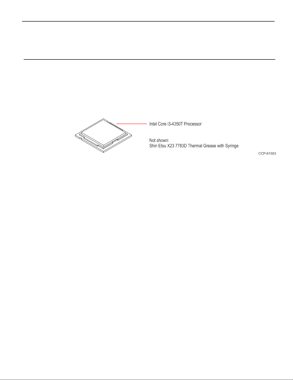
This kit contains the components to upgrade the processor of the NCRFastLane
SelfServ™ Checkout 7360.
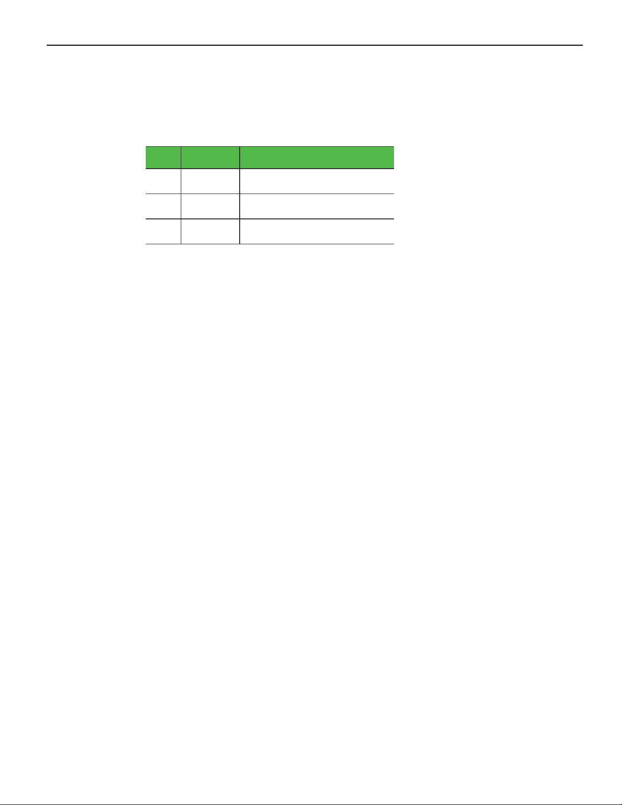
Kit Contents
Page 5
2 7360-K038 Processor Upgrade
Installation Procedure
Warning: Disconnect the AC power cord before disassembling.
Caution: Static Electricity Discharge may permanently damage your system. Discharge
any static electricity build up in your body by touching your computer's case for a few
seconds. Avoid any contact with internal parts and handle cards only by their external
edges.
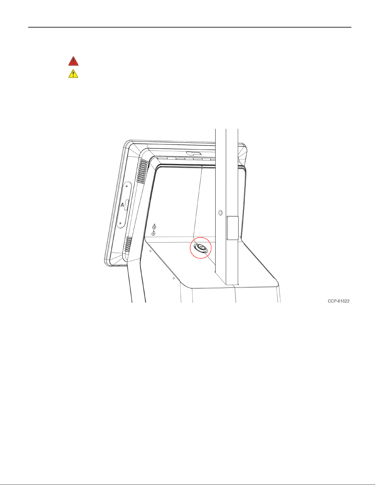
1. Use a key to unlock the tower.
Page 6

7360-K038 Processor Upgrade 3
2. Raise the terminal.
3. Disconnect all cables from the Motherboard.
4. Remove the terminal from the tower.
a. Remove the four screws that secure the terminal to the display bracket.
b. Slide the terminal as shown to detach it from the display bracket.
Page 7

4 7360-K038 Processor Upgrade
5. Lay the terminal face down on a flat surface.
Caution: Always use a soft material (cloth, foam) to protect the display screen when
placing the terminal face down.
6. Remove the Rear Cover.
a. Loosen the two captive screws that secure the Rear Cover to the chassis.
b. Pivot the Rear Cover as shown to remove it.
Page 8

7360-K038 Processor Upgrade 5
7. Loosen the spring-loaded screws of the CPUCooler.
Note: Use a sequential rotating pattern when loosening the spring-loaded screws.
Loosen each screw a little at a time to evenly raise the CPU Cooler from the CPU.
Page 9

6 7360-K038 Processor Upgrade
8. Remove the CPUCooler.
Page 10

7360-K038 Processor Upgrade 7
9. Remove the CPU from the Motherboard.
a. Press down on the CPU Socket Latch and open the Socket Cover.
b. Note the orientation of the CPU Module (gold triangle location).
c. Carefully remove the CPU with the Handi-Vac CPU Removal Tool and place it in
an anti–static packing to protect the CPU contacts from damage and
contamination.
Caution: Always use the Handi-Vac CPU Removal Tool when handling the
CPU.
Caution: Do not touch the CPU contacts.
Page 11

8 7360-K038 Processor Upgrade
10. Install the new CPU Module.
a. Using a purely vertical motion carefully place the new CPU into the CPU Socket.
(The gold triangle on the CPU must align with beveled corner on the socket.)
Caution: Always use the Handi-Vac CPU Removal Tool when handling the
CPU.
Caution: Do not touch the CPU contacts.
Caution: Do not insert the CPU at an angle or force the CPU into the socket.
b. Gently close the Socket Cover.
c. Lock the Socket by lowering the CPU Socket Latch and locking it.
11. Apply thermal grease to the top of the new CPU. Use approximately one quarter of
the contents of the grease syringe. Do not use the entire contents of the syringe. Too
much grease can block the airflow around the CPU heat spreader. The goal is for the
processor chip to be evenly covered with grease once the CPUCooler is installed.
• Do not apply the grease with a bare fingertip or talc-coated glove. Oils on skin
and particulate on the glove can contaminate the grease.
• Make sure none of the grease gets on the circuit board. Heatsink grease is a
strong electrical conductor and can short signals on the board if it crosses trace
paths.
• Recheck to make sure no foreign contaminants are present on the top of the
CPU.
Page 12

7360-K038 Processor Upgrade 9
12. Remove the old thermal grease from the CPUCooler surface.
• Remove as much of the existing grease from the CPUCooler surface using a
nonabrasive, dull object. A paper towel is an effective choice.
• Do not use a sharp, metal object such as a razor blade, knife, trowel, or similar as
it may scratch the CPUCooler surface.
• Remove remaining residue using a non-abrasive, lint free cloth and rubbing
alcohol.
• Make sure the surface is completely clean and lint free. Residue can mix with
fresh grease to cause uneven contact and non-uniform cooling.
• Make sure no grease contacts the circuit board. Thermal grease is a strong
electrical conductor and can short signals on the Motherboard.
Page 13

10 7360-K038 Processor Upgrade
13. Install the CPU Cooler on the Motherboard.
a. Position the CPUCooler over the CPU.
Page 14

7360-K038 Processor Upgrade 11
b. Tighten the spring-loaded screws.
Note: Use a sequential rotating pattern when tightening the spring-loaded
screws. Tighten each screw a little at a time to evenly lower the CPU Cooler onto
the CPU.
14. Reinstall the Rear Cover on the terminal.
Page 15

12 7360-K038 Processor Upgrade
15. Reinstall the terminal on the tower.
a. Hook the terminal onto the display bracket.
b. Slide the terminal as shown to attach it to the display bracket.
c. Secure with four screws.
16. Reconnect the cables to the Motherboard.
17. Lower the terminal then lock the tower.
 Loading...