

Page 1
Kit Instructions
2-Bag Bagwell Upgrade
7350-K140/K141/K142/K143/K145/K964
Issue C
Page 2

The product described in this document is a licensed product of NCR Corporation.
NCR is a registered trademark of NCR Corporation. NCR SelfServ™ Checkout is a trademark of NCR Corporation in the United
States and/or other countries. Other product names mentioned in this publication may be trademarks or registered trademarks of
their respective companies and are hereby acknowledged.
The terms HDMI and HDMI High-Definition Multimedia Interface, and the HDMI Logo are trademarks or registered trademarks
of HDMI Licensing LLC in the United States and other countries.
Where creation of derivative works, modifications or copies of this NCR copyrighted documentation is permitted under the terms
and conditions of an agreement you have with NCR, NCR's copyright notice must be included.
It is the policy of NCR Corporation (NCR) to improve products as new technology, components, software, and firmware become
available. NCR, therefore, reserves the right to change specifications without prior notice.
All features, functions, and operations described herein may not be marketed by NCR in all parts of the world. In some instances,
photographs are of equipment prototypes. Software screen images are representative, and in some cases, may not match a
customer’s installed software exactly. Therefore, before using this document, consult with your NCR representative or NCR office
for information that is applicable and current.
To maintain the quality of our publications, we need your comments on the accuracy, clarity, organization, and value of this book.
Please use the link below to send your comments.
Email: FD230036@ncr.com
Copyright © 2011-2019
By NCR Corporation
Global Headquarters
864 Spring St. NW
Atlanta, GA 30308
United States
All Rights Reserved
Page 3

K140Cover 1-3
Revision Record
Issue Date Remarks
A
B
C
D
Jan 2011 • First Issue
• 50DR20059
Aug 2011 • Added steps on the removal and installation of
stainless steel lower bumpers if included in the kit.
• Added steps on the removal and installation of the
rear frame support bracket.
• Added steps on the installation of the rear lower
bumper on the Backsplash if included in the kit.
• 50DR22474
July 2019 • Added to IP Kit Repository site with HTML version.
• 50DR36322
Aug 2019 • Updated Kits
• 50DR36505
Page 4

1-4
Page 5

7350 2-Bag Bagwell Upgrade
This publication provides procedures for installing a 2-Bag Bagwell to a 7350 NCR
SelfServ™ Checkout.
Kit Contents
Depending on the color variant of the Bagwell, refer to the following sections for
information about kit contents:
• 7350-K140 2-Bag Bagging Area (G/11) on the next page.
• 7350-K141 2-Bag Bagging Area (Battleship Gray) on page4.
• 7350-K142 2-Bag Bagging Area (Dark Red) on page7.
• 7350-K143 2-Bag Bagging Area (RAL 9001 Cream) on page9.
• 7350-K145 2-Bag Bagging Area (Walmart Blue) on page11.
• 7350-K964 2-Bag Bagging Area (RAL 7021 Black) on page13.
Page 6
1-2 7350 2-Bag Bagwell Upgrade
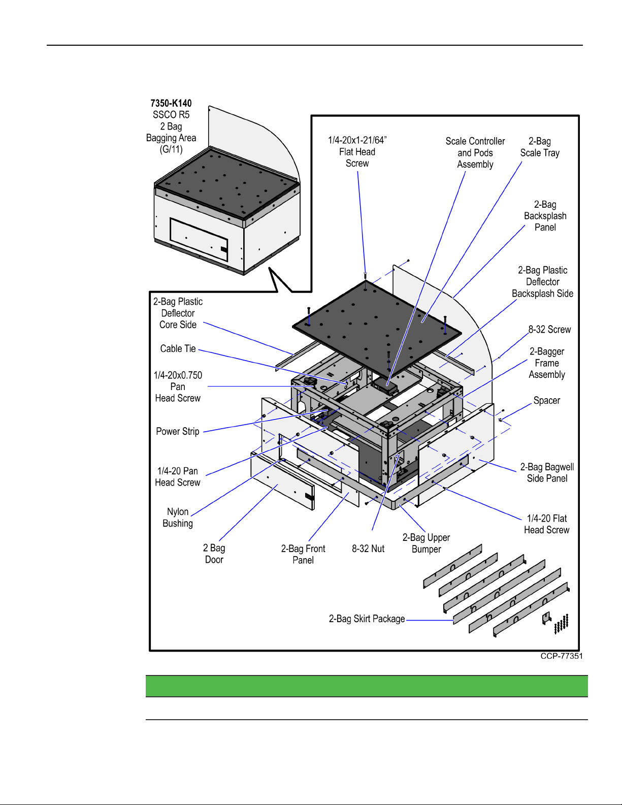
7350-K140 2-Bag Bagging Area (G/11)
Part Number Description
497-0526236 2-Bag Bagging Area (G/11)
Page 7

7350 2-Bag Bagwell Upgrade 1-3
Part Number Description
795-0283601 2-Bag Door Assembly (G/11)
795-0134201 2-Bag Backsplash Panel (G/11)
795-0134101 2-Bag Front Panel (G/11)
795-0133301 2-Bag Bagwell Side Panel (G/11)
006-8604541 Screw - 1/4-20x1/2, Pan Head, Phillips (4pcs)
497-0472268 2-Bag Scale Tray with Bag Rack Hardware
497-0466205 Skirt - 2-Bag BOM Package
497-0525620 2-Bag Frame Assembly with Leveling Feet and Casters
497-0467814 Scale Controller and Pods Assembly
497-0457054 Black Nylon Spacer 15mm OD x 10.4mm ID x 10mm L (6pcs)
497-0518273 2-Bag Upper Bumper
497-0455521 2-Bag Bagwell Backsplash Plastic Deflector
497-0455519 Core Side Plastic Deflector
006-8611143 Nut Keps, 8-32, Steel, Blue Zinc (5pcs)
006-8611505 Nylon Bushing (2pcs)
009-0005930 Cable Tie-snap in Mounting (3pcs)
006-8623998 Screw - 1/4-20 x 1-21/64’’, Phillips Flat Head, 82 Degree,
Machine Thread, Zinc-Plated Steel (4pcs)
006-8612492 Screw - 1/4-20 x 0.750", Phillips Flat Head, 82 Degree, Machine
Thread, Zinc-Plated Steel (6pcs)
006-8612446 Screw - 8-32 x 0.375" Phil Pan, Self Tapping - Type F (10pcs)
006-8616060 Screw - 1/4-20 x 0.75", Pan Head, Phillips, Zinc Plated Steel
(8pcs)
* 795-0281699 Hole Cover Label - (G/11)
* 497-0445077 Cable: (Black) 4M USB +Power (12V) to 2x4 Latch-N-Lok
* 497-0426042 Bag - 2 and 3.5 Bagger, LHC and RHC, Input Belt
497-0421485 Power Strip, IEC 4-POS, Plastic Case
* 497-0513382 Multiple Power Sources/ Disconnect Power Caution Label
* 007-9714414 Tiestrap Plain 5.60LG (2pcs)
* 497-0423108 Kit Instructions (Reference Sheet)
* Items marked with an asterisk are not called out on the image.
Page 8
1-4 7350 2-Bag Bagwell Upgrade
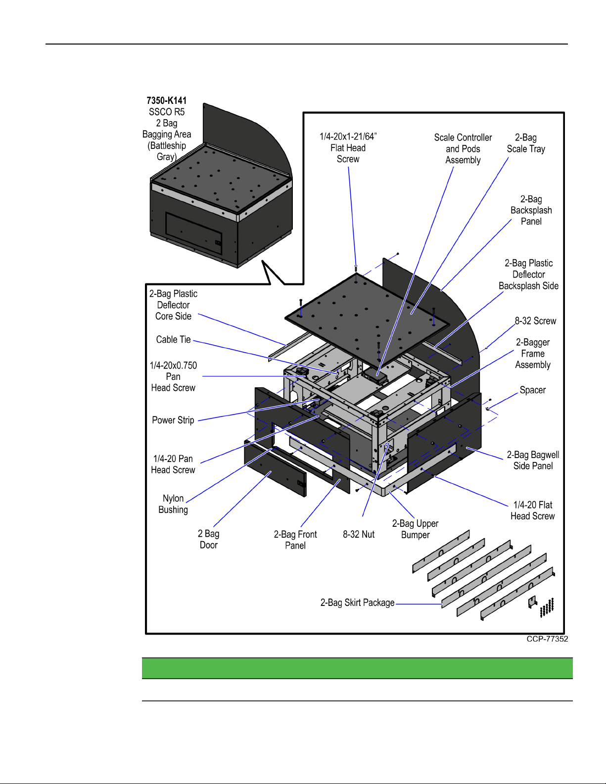
7350-K141 2-Bag Bagging Area (Battleship Gray)
Part Number Description
497-0526239 2-Bag Bagging Area (Battleship Gray)
Page 9

7350 2-Bag Bagwell Upgrade 1-5
Part Number Description
795-0283616 2-Bag Door Assembly (Battleship Gray)
795-0134216 2-Bag Backsplash Panel (Battleship Gray)
795-0134116 2-Bag Front Panel (Battleship Gray)
795-0133316 2-Bag Side Panel (Battleship Gray)
006-8604541 Screw - 1/4-20x1/2, Pan Head, Phillips (4pcs)
497-0472268 2-Bag Scale Tray with Bag Rack Hardware
497-0466205 Skirt - 2-Bag BOM Package
497-0525620 2-Bag Frame Assembly with Leveling Feet and Casters
497-0467814 Scale Controller and Pods Assembly
497-0457054 Black Nylon Spacer 15mm OD x 10.4mm ID x 10mm L (13pcs)
497-0518273 2-Bag Upper Bumper
497-0455521 2-Bag Bagwell Backsplash Plastic Deflector
497-0455519 Core Side Plastic Deflector
006-8611143 Nut Keps, 8-32, Steel, Blue Zinc (9pcs)
006-8611505 Nylon Bushing (2pcs)
006-8613174 Wire Saddle – Locking Top (3pcs)
006-8623998 Screw - 1/4-20 x 1-21/64’’, Phillips Flat Head, 82 Degree,
Machine Thread, Zinc-Plated Steel (4pcs)
006-8612492 Screw - 1/4-20 x 0.750", Phillips Flat Head, 82 Degree, Machine
Thread, Zinc-Plated Steel (13pcs)
006-8612446 Screw - 8-32 x 0.375" Phil Pan, Self Tapping - Type F (10pcs)
006-8616060 Screw - 1/4-20 x 0.75", Pan Head, Phillips, Zinc Plated Steel
(8pcs)
* 795-0281616 Hole Cover Label (Battleship Gray)
* 497-0445077 Cable: (Black) 4M USB +Power (12V) to 2x4 Latch-N-Lok
* 497-0426042 Bag - 2 and 3.5 Bagger, LHC and RHC, Input Belt
497-0421485 Power Strip, IEC 4-POS, Plastic Case
* 497-0513382 Multiple Power Sources/ Disconnect Power Caution Label
497-0518274 2-Bag Rear Door Bumper
Page 10

1-6 7350 2-Bag Bagwell Upgrade
Part Number Description
497-0518276 2-Bag Core Side Lower Back Bumper
497-0518277 2-Bag Wrap-Around Side Corner Bumper
497-0455678 2-Bag Rear Frame Support Bracket
* 497-0423108 Kit Instructions (Reference Sheet)
* Items marked with an asterisk are not called out on the image.
Page 11
7350 2-Bag Bagwell Upgrade 1-7
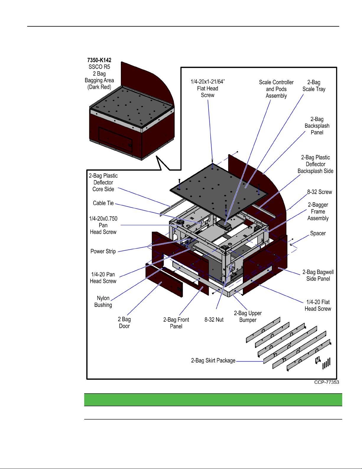
7350-K142 2-Bag Bagging Area (Dark Red)
Part Number Description
497-0526240 2-Bag Bagging Area (Dark Red)
Page 12

1-8 7350 2-Bag Bagwell Upgrade
Part Number Description
795-0283618 2-Bag Door Assembly (Dark Red)
795-0134218 2-Bag Backsplash Panel (Dark Red)
795-0134118 2-Bag Front Panel (Dark Red)
795-0133318 2-Bag Bagwell Side Panel (Dark Red)
* 795-0281618 Hole Cover Label (Dark Red)
006-8604541 Screw, 1/4-20x1/2, Pan Head, Phillips (4pcs)
497-0457054 Black Nylon Spacer 15mm OD x 10.4mm ID x 10mm L (6pcs)
497-0525620 2-Bag Frame Assembly with Leveling Feet and Casters
497-0466205 Skirt - 2 Bag BOM Package
497-0467814 Scale Controller and Pods Assembly
497-0472268 2-Bag Scale Tray with Bag Rack Hardware
006-8611143 Nut Keps, 8-32, Steel, Blue Zinc (5pcs)
006-8611505 Nylon Bushing (2pcs)
497-0455519 Core Side Plastic Deflector
497-0455521 2-Bag Bagwell Backsplash Plastic Deflector
497-0518273 2-BagUpper Bumper
009-0005930 Cable Tie-snap in Mounting (3pcs)
006-8612446 Screw - 8-32 x 0.375" Phil Pan, Self Tapping - Type F (10pcs)
006-8612492 Screw - 1/4-20 x 0.750", Phillips Flat Head, 82 Degree, Machine
Thread, Zinc-Plated Steel (6pcs)
006-8616060 Screw - 1/4-20 x 0.75", Pan Head, Phillips, Zinc Plated Steel
(8pcs)
006-8623998 Screw - 1/4-20 x 1-21/64’’, Phillips Flat Head, 82 Degree,
Machine Thread, Zinc-Plated Steel (4pcs)
497-0421485 Power Strip, IEC 4-POS, Plastic Case
* 497-0426042 Bag - 2 and 3.5 Bagger, LHC and RHC, Input Belt
* 497-0445077 Cable: (Black) 4M USB +Power (12V) to 2x4 Latch-N-Lok
* 007-9714414 Tiestrap Plain 5.60LG (2pcs)
* 497-0513382 Multiple Power Sources/ Disconnect Power Caution Label
* 497-0423108 Kit Instructions (Reference Sheet)
* Items marked with an asterisk are not called out on the image.
Page 13
7350 2-Bag Bagwell Upgrade 1-9
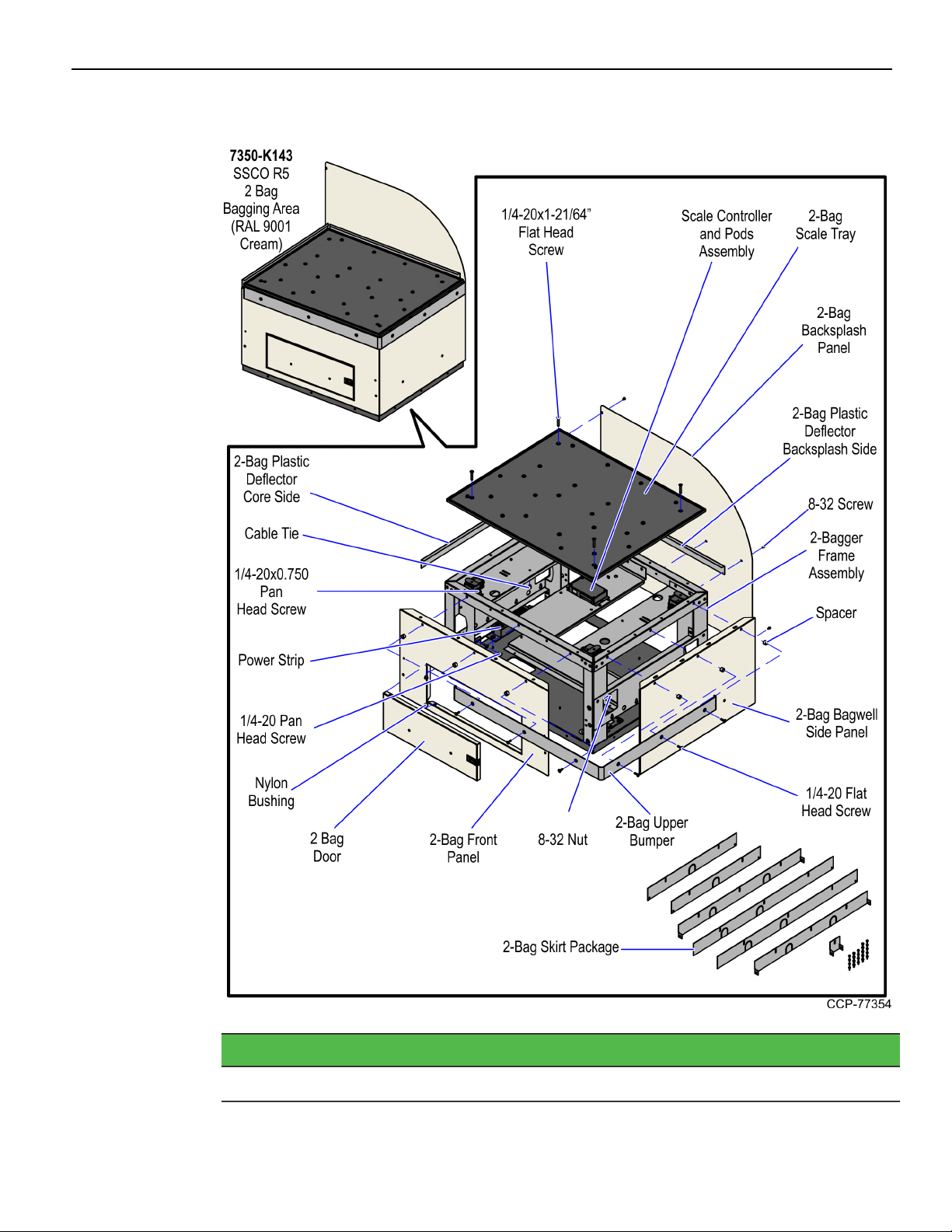
7350-K143 2-Bag Bagging Area (RAL 9001 Cream)
Part Number Description
497-0526238 2-Bag Bagging Area (RAL 9001 Cream)
Page 14

1-10 7350 2-Bag Bagwell Upgrade
Part Number Description
795-0283609 2-Bag Door Assembly (RAL 9001 Cream)
795-0134209 2-Bag Backsplash Panel (RAL 9001 Cream)
795-0134109 2-Bag Front Panel (RAL 9001 Cream)
795-0133309 2-Bag Bagwell Side Panel(RAL 9001 Cream)
006-8604541 Screw -1/4-20x1/2, Pan Head, Phillips (4pcs)
497-0472268 2-Bag Scale Tray with Bag Rack Hardware
497-0466205 Skirt - 2 Bag BOM Package
497-0525620 2-Bag Frame Assembly with Leveling Feet and Casters
497-0467814 Scale Controller and Pods Assembly
497-0457054 Black Nylon Spacer 15mm OD x 10.4mm ID x 10mm L (6pcs)
497-0518273 2-Bag Upper Bumper
497-0455521 2-Bag Bagwell Backsplash Plastic Deflector
497-0455519 Core Side Plastic Deflector
006-8611143 Nut Keps, 8-32, Steel, Blue Zinc (5pcs)
006-8611505 Nylon Bushing (2pcs)
009-0005930 Cable Tie-snap in Mounting (3pcs)
006-8623998 Screw - 1/4-20 x 1-21/64’’, Phillips Flat Head, 82 Degree,
Machine Thread, Zinc-Plated Steel (4pcs)
006-8612492 Screw - 1/4-20 x 0.750", Phillips Flat Head, 82 Degree, Machine
Thread, Zinc-Plated Steel (6pcs)
006-8612446 Screw - 8-32 x 0.375" Phil Pan, Self Tapping - Type F (10pcs)
006-8616060 Screw - 1/4-20 x 0.75", Pan Head, Phillips, Zinc Plated Steel
(8pcs)
* 795-0281609 Hole Cover Label (RAL 9001 Cream)
* 497-0445077 Cable: (Black) 4M USB +Power (12V) to 2x4 Latch-N-Lok
* 497-0426042 Bag - 2 and 3.5 Bagger, LHC and RHC, Input Belt
497-0421485 Power Strip, IEC 4-POS, Plastic Case
* 497-0513382 Multiple Power Sources/ Disconnect Power Caution Label
* 007-9714414 Tiestrap Plain 5.60LG (2pcs)
* 497-0423108 Kit Instructions (Reference Sheet)
* Items marked with an asterisk are not called out on the image.
Page 15
7350 2-Bag Bagwell Upgrade 1-11
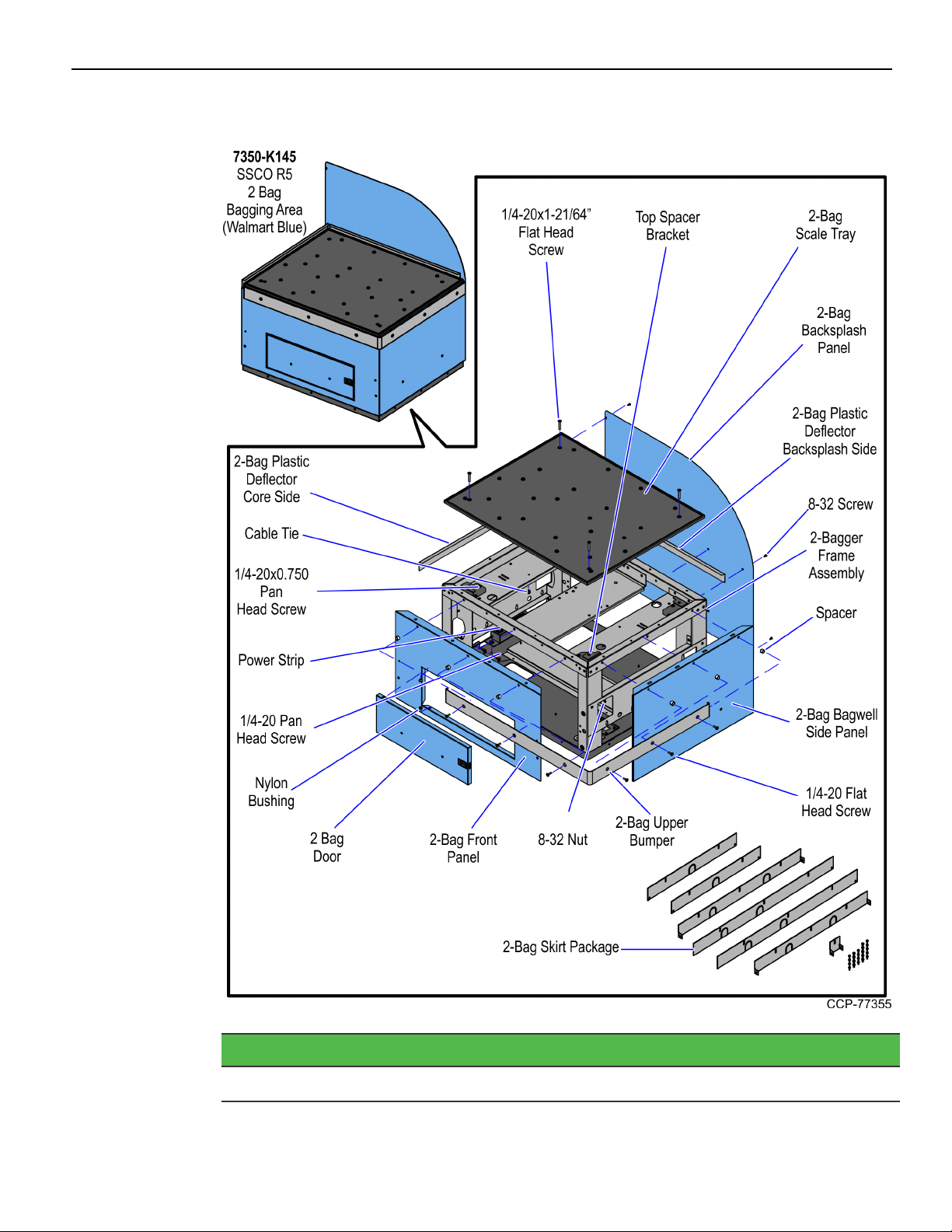
7350-K145 2-Bag Bagging Area (Walmart Blue)
Part Number Description
497-0526496 2-Bag Bagging Area (Walmart Blue)
Page 16

1-12 7350 2-Bag Bagwell Upgrade
Part Number Description
795-0283612 2-Bag Door Assembly (Walmart Blue)
795-0134212 2-Bag Backsplash Panel (Walmart Blue)
795-0134112 2-Bag Front Panel (Walmart Blue)
795-0133312 2-Bag Bagwell Side Panel (Walmart Blue)
* 795-0281612 Hole Cover Label (Walmart Blue)
006-8604541 Screw - 1/4-20x1/2, Pan Head, Phillips (4pcs)
497-0525620 2-Bag Frame Assembly with Leveling Feet and Casters
497-0466205 Skirt - 2-Bag BOM Package
497-0472268 2-Bag Scale Tray with Bag Rack Hardware
006-8611143 Nut Keps, 8-32, Steel, Blue Zinc (5pcs)
006-8611505 Nylon Bushing (2pcs)
497-0455519 Core Side Plastic Deflector
497-0455521 2-Bag Bagwell Backsplash Plastic Deflector
009-0005930 Cable Tie-snap in Mounting (3pcs)
006-8612446 Screw - 8-32 x 0.375" Phil Pan, Self Tapping - Type F (14pcs)
006-8616060 Screw - 1/4-20 x 0.75", Pan Head, Phillips, Zinc Plated Steel
(8pcs)
006-8623998 Screw - 1/4-20 x 1-21/64’’, Phillips Flat Head, 82 Degree,
Machine Thread, Zinc-Plated Steel (4pcs)
497-0421485 Power Strip, IEC 4-POS, Plastic Case
* 497-0426042 Bag - 2 AND 3.5 Bagger, LHC and RHC, Input Belt
* 007-9714414 Tiestrap Plain 5.60LG (2pcs)
* 497-0513382 Multiple Power Sources/ Disconnect Power Caution Label
497-0521432 Top Spacer Bracket (4pcs)
* 497-0423108 Kit Instructions (Reference Sheet)
* Items marked with an asterisk are not called out on the image.
Page 17

7350 2-Bag Bagwell Upgrade 1-13
7350-K964 2-Bag Bagging Area (RAL 7021 Black)
Part Number Description
497-0526237 2-Bag Bagging Area (RAL 7021 Black)
Page 18

1-14 7350 2-Bag Bagwell Upgrade
Part Number Description
795-0283607 2-Bag Door Assembly (RAL 7021 Black)
795-0134207 2-Bag Backsplash Panel (RAL 7021 Black)
795-0134107 2-Bag Front Panel (RAL 7021 Black)
795-0133307 2-Bag Bagwell Side Panel (RAL 7021 Black)
006-8604541 Screw - 1/4-20x1/2, Pan Head, Phillips (4pcs)
497-0472268 2-Bag Scale Tray with Bag Rack Hardware
497-0466205 Skirt - 2-Bag BOM Package
497-0525620 2-BagFrame Assembly with Leveling Feet and Casters
497-0467814 Scale Controller and Pods Assembly
497-0457054 Black Nylon Spacer 15mm OD x 10.4mm ID x 10mm L (6pcs)
497-0518273 2-Bag Upper Bumper
497-0455521 2-Bag Bagwell Backsplash Plastic Deflector
497-0455519 Core Side Plastic Deflector
006-8611143 Nit Keps, 8-32, Steel, Blue Zinc (5pcs)
006-8611505 Nylon Bushing (2pcs)
009-0005930 Cable Tie-snap in Mounting (3pcs)
006-8623998 Screw - 1/4-20 x 1-21/64’’, Phillips Flat Head, 82 Degree,
Machine Thread, Zinc-Plated Steel (4pcs)
006-8612492 Screw - 1/4-20 x 0.750", Phillips Flat Head, 82 Degree, Machine
Thread, Zinc-Plated Steel (6pcs)
006-8612446 Screw - 8-32 x 0.375" Phil Pan, Self Tapping - Type F (10pcs)
006-8616060 Screw - 1/4-20 x 0.75", Pan Head, Phillips, Zinc Plated Steel
(8pcs)
* 795-0281607 Hole Cover Label (RAL 7021 Black)
* 497-0445077 Cable: (Black) 4M USB +Power (12V) to 2x4 Latch-N-Lok
* 497-0426042 Bag - 2 and 3.5 Bagger, LHC and RHC, Input Belt
497-0421485 Power Strip, IEC 4-POS, Plastic Case
* 497-0513382 Multiple Power Sources/ Disconnect Power Caution Label
* 007-9714414 Tiestrap Plain 5.60LG (2pcs)
* 497-0423108 Kit Instructions (Reference Sheet)
* Items marked with an asterisk are not called out on the image.
Page 19

7350 2-Bag Bagwell Upgrade 1-15
Installation Procedures
Installing the Bagwell upgrade involves the following procedures:
• Removing Existing Bagwell on the next page.
• Changing Bagwell Orientation on page21.
Note: This procedure may be optional.
• Installing New Bagwell on page28.
• Installing Bagwell Skirt Panels on page36.
• Routing Cables on page38.
Page 20

1-16 7350 2-Bag Bagwell Upgrade
Removing Existing Bagwell
To remove an existing 2-Bag Bagwell, follow these steps:
Note: To remove a 1-Bag Bagwell refer to 7350-K120/K121/K122/K123/K125/K962/K967
2-Bag Bagwell Upgrade. To remove a 3-Bag Bagwell refer to 7350K160/K162/K164/K165/K996 3-Bag Bagwell Upgrade.
1. Detach the Scale Tray from the Bagwell by removing four (4) flat head screws.
Note: Remove bag racks if present.
Page 21

7350 2-Bag Bagwell Upgrade 1-17
2. Remove the clear plastic deflectors from the Backsplash and side of the Core.
Note: Leave the Core side deflector in its place if the new Bagwell is attached on the
same side.
Note: The 7350-K145 (Walmart Blue) variant does not have plastic deflectors and
bumpers.
Page 22

1-18 7350 2-Bag Bagwell Upgrade
3. Disconnect the following cables:
Note: The 7350-K145 (Walmart Blue) variant uses Top Spacer Brackets instead of a
Scale Controller and Scale Pods.
• USB Power Cable from the Scale Controller
• Local Area Network (LAN) Cable from the Customer Interface
• ACPower Out Cables from the Power Strip
• AC Power In Cable from the Power Strip
Note: Remove cables from any routing clips or tie wraps if needed.
4. Route the following cables through the cable access hole:
Note: The 7350-K145 (Walmart Blue) variant uses Top Spacer Brackets instead of a
Scale Controller and Scale Pods.
Bagwell Cable Access Hole
• AC Power In Cable
Core Cable Access Hole
• USB Power Cable
• Local Area Network (LAN) Cable
• AC Power Out Cables
Note: Local Area Network (LAN) Cable and ACPower In Cable may be routed
differently depending on the installation conditions.
Page 23

7350 2-Bag Bagwell Upgrade 1-19
5. Remove the upper rear screw attaching the Backsplash to the Core.
6. Remove the Bagwell by doing the following:
a. Remove the two (2) bottom screws attaching the Bagwell to the Core. Screws are
located on either side of power strip.
Page 24

1-20 7350 2-Bag Bagwell Upgrade
b. Loosen the two (2) upper screws, but do not remove.
c. Lift Bagwell up and away from Core. The upper screw heads will pass through
the key holes in the Bagwell side support.
Note: The two (2) upper screws may be left in place if a new Bagwell will be
installed in the same orientation. Otherwise, remove the screws from the side of
the Core.
Page 25

7350 2-Bag Bagwell Upgrade 1-21
Changing Bagwell Orientation
To change the Bagwell from right hand to left hand orientation, follow these steps:
Note: These steps should be done before attaching the Bagwell to the Core.
1. Detach the Scale Tray from the Bagwell by removing four (4) flat head screws.
Page 26

1-22 7350 2-Bag Bagwell Upgrade
2. Remove the bumpers by doing the following:
Note: Do not remove the front access door bumper
a. Detach the lower-rear bumper from the Bagwell by removing two (2) flat head
screws.
b. Detach the Backsplash the Bagwell by removing seven (7) screws.
Page 27

7350 2-Bag Bagwell Upgrade 1-23
c. Detach rear support frame from the Bagwell by removing four (4) nuts.
d. Detach the upper bumper from the Bagwell by removing six (6) flat head screws
and spacers, as shown in the image below.
Page 28

1-24 7350 2-Bag Bagwell Upgrade
e. Detach the wrap-around side bumper by removing three (3) flat head screws and
spacers, as shown in the image below.
3. Remove two (2) nuts securing the front panel to the Bagwell frame located at the
inside corner posts.
Page 29

7350 2-Bag Bagwell Upgrade 1-25
4. Pull down the front panel and then pull out to disengage from the slots in the
Bagwell frame base, as shown in the image below.
5. Install the front panel on the opposite side of the Bagwell and secure it with two (2)
nuts.
Note: Ensure that the the lower hook features are properly aligned with the slots in
the Bagwell frame base.
Page 30

1-26 7350 2-Bag Bagwell Upgrade
6. Install the bumpers to the Bagwell by doing the following:
Note: Do not reinstall Scale Tray, Backsplash panel, and rear lower bumper (if
present). For more information, refer to Installing New Bagwell on page28.
a. Attach the rear frame support by using four (4) nuts.
b. Attach the upper stainless steel bumper to the Bagwell by using six (6) flat head
screws and spacers.
Page 31

7350 2-Bag Bagwell Upgrade 1-27
c. Attach the wrap-around bumper to the Bagwell by using three (3) flat head
screws and spacers.
Page 32

1-28 7350 2-Bag Bagwell Upgrade
Installing New Bagwell
To install the new Bagwell, follow these steps:
Note: If changing the Bagwell orientation (Left-Hand or Right-Hand), ensure that the
orientation is changed before installing the new Bagwell to the Core.
1. Remove the Scale Tray from the Bagwell.
2. Remove the lower access panel from the Core side where the new Bagwell will be
attached. Reinstall the access panel on the opposite side of the Core.
Note: This panel does not need to be reinstalled when attaching a Bagwell to a NoBag Unit.
Page 33

7350 2-Bag Bagwell Upgrade 1-29
3. Lower all the leveling feet of the Bagwell slightly beyond the height of the casters to
assist in lining up the Core and the Bagwell mounting holes.
4. Install the new Backsplash panel using seven (7) screws.
Page 34

1-30 7350 2-Bag Bagwell Upgrade
5. If not already present, partially thread the two (2) upper screws on the Bagwell side
of the Core. Leave approximately ¼ inch of the threads exposed.
6. Mate the new Bagwell to the Core by lifting the frame up and over the partially
threaded screws.
Note: Ensure that the two frontmost key holes on the Bagwell are used.
Page 35

7350 2-Bag Bagwell Upgrade 1-31
7. Tighten the two (2) screws and install the two (2) lower screws that connect the
Bagwell and the Core.
8. Install the upper rear screw attaching the Backsplash panel to the Core.
Note: Adjust the leveling feet if the slot does not line up well.
Page 36

1-32 7350 2-Bag Bagwell Upgrade
9. If present, install rear lower bumper using two (2) plastic spacers and two (2) flat
head screws on the Backsplash.
10. Route the following cables through the cable access hole:
Note: The 7350-K145 (Walmart Blue) variant uses Top Spacer Brackets instead of a
Scale Controller and Scale Pods.
Bagwell Cable Access Hole
• AC Power In Cable
Core Cable Access Hole
• USB Power Cable
• Local Area Network (LAN) Cable
• AC Power Out Cables
For more information, refer to Routing Cables on page38.
Page 37

7350 2-Bag Bagwell Upgrade 1-33
11. Remove four (4) yellow shipping spacers from the scale pods before installing the
Scale Tray.
Note: The 7350-K145 (Walmart Blue) variant uses Top Spacer Brackets instead of a
Scale Controller and Scale Pods.
Page 38

1-34 7350 2-Bag Bagwell Upgrade
12. Install the Scale Tray on the Bagwell using four (4) flat head screws.
Note: Ensure that the surface marked BACK is facing towards the back of the unit.
! Important: Use the correct screw length. Tighten the screws from six to eight
pounds. Do not overtighten the screws to prevent inaccurate scale readings.
Page 39

7350 2-Bag Bagwell Upgrade 1-35
13. Install clear plastic deflectors to the Core side and rear side of the Bagwell.
Ensure that the deflectors meet at the rear and Core side corners, and should rest
against the Bagwell frame.
! Important: Plastic deflectors must not touch the Scale Tray surface to avoid
scale errors.
14. Attach the Bagwell Skirt Panels. For more information, refer to Installing Bagwell
Skirt Panels on the next page.
15. Do the following:
• Level the unit and attach the bag racks, if necessary. For more information, refer
to the 7350 NCR SelfServ™ Checkout (7350) Hardware Installation Guide (B005–
0000–1826).
• Test scale operation in PML. For more information, refer to the NCR FastLane
SelfServ™ Checkout Profile Manager Lite (PML) User Guide for ADD 3.X (B0050000-2279).
Page 40

1-36 7350 2-Bag Bagwell Upgrade
Installing Bagwell Skirt Panels
To install Bagwell skirt panels, follow these steps:
1. On the side of the Bagwell, do the following:
a. Attach the skirt panel to the skirt brackets by aligning the open slots in the skirt
panel with the screw holes in the skirt bracket.
b. Secure the skirt panel to the bracket using three (3) screws.
c. Adjust the skirt panel so that it is flush with the floor.
d. Tighten the screws to secure the skirt in place.
Page 41

7350 2-Bag Bagwell Upgrade 1-37
2. On the front and back of the Bagwell, do the following:
Note: The front and back skirt panels of the Bagwell must be installed after the side
skirt panel of the Bagwell.
a. Attach the front and back skirt panels to the skirt brackets by aligning the open
slots of both skirt panels with the screw holes in the securing bracket.
b. Secure both skirt panels to the bracket using eight (8) screws.
c. Adjust the skirt panel so that it is flush with the floor.
d. Tighten the screws to secure the skirt in place.
Page 42

1-38 7350 2-Bag Bagwell Upgrade
Routing Cables
To route cables when installing a new Bagwell follow these steps:
Note: If a new Bagwell is installed to a No-Bag unit, refer to Routing Cables for No-Bag
unit on page41 first for additional steps.
Note: Use the new pre-installed USB Power Cable only when installing a new Bagwell
to a No-Bag unit. If not, reuse the existing USB Power Cable of the previous Bagwell.
1. Retrieve the USBPower Cable from the Core and route to the Scale Controller
through the smaller opening of the Bagwell frame as shown in the image below.
Page 43

7350 2-Bag Bagwell Upgrade 1-39
2. Tie the USB Power Cable with cable ties to hold it in place.
3. Route the Local Access Network (LAN) Cable from the Core to the Customer
Interface through the smaller opening of the Bagwell frame as shown in the image
below.
Page 44

1-40 7350 2-Bag Bagwell Upgrade
4. Route the AC Power Out and AC Power In cables and then connect to the Power
Strip, as shown in the image below.
Page 45

7350 2-Bag Bagwell Upgrade 1-41
Routing Cables for No-Bag unit
These are additional steps in routing cables when upgrading a No-Bag unit to a 1-Bag
unit:
Note: Use the new USB Power Cable. Route the USBPower Cable to the E-Box first
before installing new Bagwell.
1. Unlock and open the upper Cabinet Door.
2. Lift the Scale Plate from the Scanner.
Page 46

1-42 7350 2-Bag Bagwell Upgrade
3. Do the following to remove the Scanner/Scale from the scanner bucket area.
a. Grasp the front of the Scanner and lift up.
b. Grasp the back of the Scanner and slide scanner out of the bucket area.
4. Detach the rear Core panel by removing six (6) screws to access the main cable
bundle and Power Strip.
Page 47

7350 2-Bag Bagwell Upgrade 1-43
5. Tilt the E-Box Bracket forward to easily access the cables.
6. Unplug the pre-installed USB Power Cable from the Scale Controller in the new
Bagwell and plug host connector to the USB M Port of the E-Box.
Page 48

1-44 7350 2-Bag Bagwell Upgrade
7. Tie the Scale Controller Cable to the main bundle by using six (6) cable ties.
Note: Secure the main cable to the E-Box with the first two (2) cable ties.
8. Continue routing the cable down the back of the Receipt Printer, as shown in the
image below. Push all the cable slack to the rear of the Core.
Page 49

7350 2-Bag Bagwell Upgrade 1-45
9. Ensure that the cable bundle is not in contact with the Tri-Light pole bracket,
DVDDrive, and ventilation fan studs when the E-Box is tilted from Up to Down
positions as shown in the image below.
10. Rotate the E-Box back up. Help feed the cables down the back of the Receipt Printer
to ensure that the cables are not tangled when the E-Box is rotated.
Page 50

1-46 7350 2-Bag Bagwell Upgrade
11. Install the Scanner/Scale. To install the Scanner/Scale, follow these steps:
a. Grasp the Scanner/Scale by its handles and lower it into the checkstand cutout.
Caution: Be careful not to damage any of the cables.
b. Place the back of Scanner/Scale on the two supports located on the E-Box
mount.
c. Lower the Scanner/Scale unto the scanner bucket area.
d. Install the Scale Plate by placing it on top of the load cells.
Page 51

7350 2-Bag Bagwell Upgrade 1-47
12. Ensure the E-Box can rotate freely by adjusting the position of the cable as needed.
USB Power Cable should be routed through the left hand lower Core access cutout
into the new Bagwell.
13. Unplug the ACPower Out and AC Power In cables from the Power Strip. ACPower
In Cable will be reused in the new Bagwell. AC Power Out Cable should be routed
either through the left-hand or right-hand lower Core access cutout into the new
Bagwell.
Note: The Power Strip remains on the rear Core wall but not reused.
14. Finish routing the cables into the Bagwell. For more information, refer to Routing
Cables on page38.
Page 52

1-48
 Loading...