

NCR 7197 II Owner's Manual
NCR 7197 Thermal Receipt Printer:
Series II
Owner's Manual
B005-0000-2068
Revision B
February, 2012

The product described in this book is a licensed product of NCR Corporation.
NCR is the registered trademark of NCR Corporation. Other trademarks and registered trademarks are the property of their
respective holders.
It is the policy of NCR Corporation (NCR) to improve products as new technology, components, software, and firmware
become available. NCR, therefore, reserves the right to change specifications without prior notice.
All features, functions, and operations described herein may not be marketed by NCR in all parts of the world. In some
instances, photographs are of equipment prototypes. Therefore, before using this document, consult with your NCR
representative or NCR office for information that is applicable and current.
To maintain the quality of our publications, we need your comments on the accuracy, clarity, organization, and value of this
book.
Address correspondence to:
Retail Systems GroupAtlanta
NCR Corporation
2651 Satellite Blvd.
Duluth, GA 30136
Copyright © 2011
By NCR Corporation
Dayton, Ohio U.S.A.
All Rights Reserved
ii

Important Information to the User
In order to ensure compliance with the Product Safety, FCC and CE marking requirements, you must use the power supply,
power cord, and interface cable which were shipped with this product or which meet the following parameters:
Power Supply
UL Listed (QQGQ), Class 2 power supply with SELV (Secondary Extra Low Voltage), non-energy hazard output, limited
energy source, input rated 100-240 Vac, 1.5/0.8 A, 50/60 Hz, output rated 24 Vdc, 2.3 A. or 3.125A.
Use of this product with a power supply other than the NCR power supply will require you to test this power supply and
NCR printer for FCC and CE mark certification.
Interface Cable
A shielded (360 degree) interface cable must be used with this product. The shield must be connected to the frame or earth
ground connection or earth ground reference at EACH end of the cable.
Use of a cable other than described here will require that you test this cable with the NCR printer and your system for FCC
and CE mark certification.
Power Cord
A UL listed, detachable power cord must be used for this product. For applications where the power supply module may be
mounted on the floor, a power cord with Type SJT marking must be used. For applications outside the US, power cords which
meet the particular country’s certification and application requirements should be used.
Use of a power cord other than described here may result in a violation of safety certifications which are in force in the
country of use.
iii

Wichtige Benutzerinformationen:
Um die Produktsicherheit und die FCC und CE-Markierungsanforderungen bei der Benutzung des Druckers sicherzustellen,
müssen entweder das mitgesante Netzgerät, Netzanschlußkabel und Verbindungskabel verwendet werden oder folgende
Anforderungen müssen erfüllt sein:
Netzgerät:
Das Netzgerät muß ein UL verzeichnetes (QQGQ) Netzgerät der Klasse 2 mit SELV (Sekundärextraniederspannung),
Nichtenergie Gefahrenausgang, begrenzter Energiequelle, einer Aufnahmeleistung von 100-240 VAC, 1.5/0.8 A und 50/60
Hz, und einer Leistungsabgabe von 24 VDC, 3.125 A.c sein.
Die Benutzung des Produktes mit einem Netzgerät, daß nicht von NCR mitgeliefert wurde erfordert das Testen des
Netzgerätes mit dem NCR Drucker auf FCC und CE-Markierungs Befolgung.
Verbindungskabel:
Bei der Benutzung dieses Produkts muß ein abgeschirmtes (360 Grad) Verbindungskabel benutzt werden. Die
Abschirmleitung muß entweder mit dem Rahmens des Gerätes oder der Erde verbunden sein oder alternativ müssen alle
Enden des Kabels geerdet werden.
Falls das Verbindungskabel nicht in der hier beschrieben Art benutzt wird, muessen das Kabel und der NCR Drucker auf die
FCC und CE-Markierungs Befolgung überprüft werden.
Netzanschlußkabel:
Für dieses Produkt muß ein in UL aufgelistete, abnehmbares Netzanschlußkabel benutzt werden. Falls das Netzgerät fest auf
dem Boden montiert ist, muß ein Netzanschlußkabel mit der SJT Markierung benutzt werden. Für Anwendungen außerhalb
der USA, sollte ein Netzanschlußkabel benutzt werden, daß der Zertifizierung und Bestimmung des jeweiligen Landes
entspricht.
Das Abweichen der hier beschriebenen Benutzungsanleitung des Netzanschlußkabels kann gegen die gesetzlichen
Sicherheitsbestimmungen des jeweiligen Landes verstoßen.
iv

用户须知
为了确保产品安全和遵守中国电磁兼容(EMC)规定,必须使用随产品附带或符合下列参数的电源,电源线和接口电缆:
电源
中国强制性产品认证, 输入为 : 交流 100 ~ 240 伏, 1.5/0.8 安倍,
如使用本产品与非
产品安全和中国电磁兼容(EMC)规定
接口电缆
本产品必须使用屏蔽(
使用没有在这里描述的接口电缆将要求您必须测试接口电缆和
电源线
中国强制性产品认证, 可拆卸的电源线
使用没有在这里描述的电源线可能导致在该国的安全证书失效
销售打印机的安全规定
安全注意事项
维修
注意:本产品不含有用户可自行更换的部件,如需更换,请联系有资质的技术人员。
保险丝的更换
注意:为防止失火只可用相同规格的保险丝进行更换,
NCR
生产的电源产品, 必须测试电源和 NCR 生产的打印机以符合
360
度)接口电缆。屏蔽层必须连接到金属框架或接地或接口电缆两端的接地参考
.
50/60
赫兹, 输出为: 直流 24伏,
NCR
生产的打印机以符合产品安全和中国电磁兼容
2.3或3.125安倍
(EMC)规定
안전주의사항
서비스
주의 :이 제품은 서비스 부품을 포함하지 않고 있습니다. 서비스는 자격이 있는 서비스 기술자에 의해 제공됩니다.
퓨즈교체
주의: 화재의 위험에 대한 계속적인 보호를 위해 같은 타입과 등급의 퓨즈로 교체해야 합니다. 。
한국 업무용(A급 기기) 방송통신기자재
이 기기는 업무용(A급) 전자파적합기기로서 판매자 또는 사용자는 이 점을 주의하시기 바라며, 가정 외의 지역에서 사용하는 것을
목적으로 합니다.
v

Federal Communications Commission (FCC)
Radio Frequency Interference Statement
Warning: Changes or modifications to this unit not expressly approved by the party responsible for compliance could void the
user’s authority to operate the equipment.
Note: This equipment has been tested and found to comply with the limits for a Class A digital device, pursuant to Part 15 of
the FCC Rules. These limits are designed to provide reasonable protection against harmful interference when the equipment is
operated in a commercial environment. This equipment generates, uses, and can radiate radio frequency energy and, if not
installed and used in accordance with the instruction manual, may cause harmful interference to radio communications.
Operation of this equipment in a residential area is likely to cause harmful interference in which case the user will be required
to correct the interference at his own expense.
Communication Cables
Shielded communication cables must be used with this unit to ensure compliance with the Class A FCC limits.
Information to User
This equipment must be installed and used in strict accordance with the manufacturer's instructions. However, there is no
guarantee that interference to radio communications will not occur in a particular commercial installation. If this equipment
does cause interference, which can be determined by turning the equipment off and on, the user is encouraged to contact NCR
immediately.
The NCR company is not responsible for any radio or television interference caused by unauthorized modification of this
equipment or the substitution or attachment of connecting cables and equipment other than those specified by NCR. The
correction of interferences caused by such unauthorized modification, substitution or attachment will be the responsibility of
the user.
Industry Canada (IC)
Radio Frequency Interference Statement
This Class A digital apparatus meets all requirements of the Canadian Interference-Causing Equipment Regulations.
Cet appareil numérique de la classe A respecte toutes les exigences du Règlement sur le matériel brouilleur du Canada.
vi

无线电频率干扰声明
用户须知
本设备已经过测试,证明其符合 A 级数字设备的限定。这些限制旨在对设备在商业环境中运作时提供合理的保护,以防有害干
扰。本设备产生,使用,并能发射无线电频率能量.因此如果不按照使用说明书安装和使用,可能对无线电通讯造成有害干扰. 如
果在住宅区使用本设备很可能造成干扰. 用户将被要求自费纠正干扰 。
对于未经授权的修改或使用
校正由此而产生的干扰将是用户的责任。用户需注意:未经
中国电磁兼容声明:
此为A级产品,在生活环境中,该产品可能会造成无线电干扰。在这种情况下,可能需要用户自费对其干扰采取切实可行的措
施。
NCR
规定以外的其他附件替换或连接电缆及设备,
NCR
批准的改装可能导致用户无权操作本设备
NCR
不负责.
vii

Quick Reference
This Quick Reference will direct you to key areas of the Owner’s Manual. For a complete
listing of topics, consult the Table of Contents or the Index.
Setting Up the Printer .................................................... page 7
Basic requirements for unpacking and installation, connecting the printer, turning it on,
and running the print test.
Running the Data Scope Mode ................................... page 45
Instructions for running the data scope mode.
Troubleshooting ............................................................ page 37
Information on correcting problems with the printer.
viii

How to Use this Book
Use this book as a general and technical reference manual and as a guide when replacing
parts on the printer. The service guide is intended as a guide for service representatives,
field engineers, and those who will be installing and learning about the 7197 Series II
printer. It can also be used as a reference for service courses.
See the Quick Reference page, the Contents, or the Index for detailed listings of what is
contained in this book.
Who Should Use this Book?
You must be a trained service representative to service the 7197 Series II Thermal Receipt
printer.
How to Obtain More Information
For more information see the following documents:
7197 Series II Receipt Printer: Service Manual (B005-000-2069)
7197 Series II Receipt Printer: Parts Identification Manual (B005-000-2070)
For this and additional copies of the Owner’s Manual, contact your sales representative.
Revision Record
Issue Date Remarks
A June 2011 First printing
B Apr 2112 Update
ix

7197 Series II Owner’s Manual Contents
Contents
Quick Reference ................................................................................................................... viii
How to Use this Book..................................................................................................ix
Who Should Use this Book?.......................................................................................ix
How to Obtain More Information.............................................................................ix
Revision Record ......................................................................................................................ix
Contents ...................................................................................................................................ix
Chapter 1: About the 7197 Series II Printer 1
Features .....................................................................................................................................2
Receipt Station...............................................................................................................2
General Features........................................................................................................... 3
Options...................................................................................................................................... 3
Thermal Print Head................................................................................................................. 3
Ordering Paper and Supplies................................................................................................. 5
Ordering Thermal Receipt Paper................................................................................5
Ordering Other Supplies .............................................................................................6
Ordering Documentation ............................................................................................ 6
Cleaning the Printer................................................................................................................. 7
Cleaning the Cabinet....................................................................................................7
Cleaning the Thermal Print Head ..............................................................................8
Chapter 2: Setting Up and Using the Printer 8
What Is in the Box? ..................................................................................................................8
Removing the Packing Material .................................................................................9
Repacking the Printer.................................................................................................10
Choosing a Location..............................................................................................................10
Wall mounted.............................................................................................................. 11
Setting Switches .....................................................................................................................12
Connecting the Cables........................................................................................................... 13
About the Universal Serial Bus............................................................................................ 16
Advantages of USB connections............................................................................... 16
Advantages of the NCR USB Solution..................................................................... 16
Checking for USB Support on the Host Computer ...........................................................17
Host Configuration.....................................................................................................17
Configuring the Printer......................................................................................................... 17
Installing the USB Virtual COM Port Printer Driver when USB Type ION (EPiC)...... 20
Checking the Installation ......................................................................................................25
Configuring Serial Port Number Assignments..................................................................27
Serial Port Configuration Methods ..........................................................................27
Uninstalling the Drivers ............................................................................................27
Using the Printer.................................................................................................................... 29
Loading and Changing the Receipt Paper.......................................................................... 30
Removing the Paper Roll...........................................................................................30
Loading the Paper Roll ..............................................................................................32
Advancing Paper........................................................................................................33
August 2011
ix

7197 Series II Owner’s Manual Contents
Chapter 3: Solving Problems 39
Green LED Does Not Come On/Printer Will Not Print................................................... 40
Green LED Blinking (Slow) ..................................................................................................40
Green LED Blinking (Fast).................................................................................................... 40
Receipt Printing is Light or Spotty ......................................................................................41
Other Serious Problems.........................................................................................................42
Contacting a Service Representative................................................................................... 42
Chapter 4: Diagnostics 32
Level 0 Diagnostics................................................................................................................ 32
Level 1 Diagnostics................................................................................................................ 32
Printer Configuration................................................................................................. 33
Configuring the Printer..............................................................................................35
Communication Interface Modes............................................................................. 38
Diagnostic Modes.......................................................................................................41
Emulation/Software Options ...................................................................................42
Hardware Options...................................................................................................... 48
Default Code Page...................................................................................................... 52
DHCP mode ................................................................................................................55
Mfg Adjustment:......................................................................................................... 55
Level 2 Diagnostics................................................................................................................ 60
Level 3 Diagnostics................................................................................................................ 61
Chapter 5: Communication 32
Communication Overview ...................................................................................................32
Interface .......................................................................................................................32
Sending Commands................................................................................................... 32
RS-232C Interface (Standard Model)................................................................................... 33
Print Speed and Timing............................................................................................. 33
XON/XOFF Protocol..................................................................................................34
DTR/DSR Protocol.....................................................................................................34
RS-232C Technical Specifications............................................................................. 35
Setting Extra RS-232C Options .................................................................................35
Ethernet Interface (Ethernet Model).................................................................................... 36
Protocol ........................................................................................................................36
Ethernet Connection Port .......................................................................................... 37
TCP Socket communication ......................................................................................38
UDP Socket communication .....................................................................................38
Multiple Connection ..................................................................................................38
Connector................................................................................................................................39
Chapter 6: Commands 67
Command Conventions........................................................................................................67
Introduction............................................................................................................................ 67
List of Commands and Location.......................................................................................... 67
By Command Code ....................................................................................................68
By Function.................................................................................................................. 72
Printer Function Commands..................................................................................... 72
Vertical Positioning and Print...................................................................................72
August 2011
x

7197 Series II Owner’s Manual Contents
Horizontal Positioning Commands .........................................................................73
Print Characteristic Commands................................................................................73
Graphics Commands..................................................................................................74
Status Commands....................................................................................................... 75
Real Time Commands................................................................................................ 75
Unsolicited Status Update......................................................................................... 75
Barcode Commands ...................................................................................................76
Page Mode Commands.............................................................................................. 76
Macro Commands ......................................................................................................77
User Data Storage Commands.................................................................................. 77
Asian Character Commands..................................................................................... 77
Flash Download Commands.....................................................................................77
Comparison Chart ......................................................................................................78
Command Descriptions ........................................................................................................79
Printer Function Commands..................................................................................... 80
Vertical Positioning and Print Commands .............................................................87
Horizontal Positioning Commands .........................................................................93
Print Characteristic Commands..............................................................................100
Graphics Commands................................................................................................ 116
Status Commands..................................................................................................... 126
Real Time Commands.............................................................................................. 140
Unsolicited Status Update Validation ...................................................................148
Bar Code Commands ...............................................................................................153
Caution :..................................................................................................................... 160
Macro Commands ....................................................................................................173
User Data Storage Commands................................................................................ 175
Asian Character Commands................................................................................... 186
Flash Download Commands...................................................................................190
Chapter 7: Reflashing the Printer Firmware 197
Flash Utility Information ....................................................................................................197
File Configurations...................................................................................................197
Printer Languages Cross Reference .......................................................................198
Chapter 8: Configuration Network 204
Summary............................................................................................................................... 204
Display format of Configuration setting page................................................................. 204
TCP/IP Setting .....................................................................................................................208
SNMP Setting .......................................................................................................................210
Other setting .........................................................................................................................211
Reset Window ......................................................................................................................212
IP address automatic acquisition.......................................................................................213
Appendix A: Specifications 214
Printing Specifications.........................................................................................................214
Power Requirements ...........................................................................................................215
Environmental Conditions .................................................................................................215
Reliability ..............................................................................................................................216
Dimensions and Weight...................................................................................................... 216
August 2011
xi

7197 Series II Owner’s Manual Contents
Density of Receipt Print Lines............................................................................................ 216
Duty Cycle Restrictions (Printing Solid Blocks) .............................................................. 216
Appendix B: Reflashing the Printer Firmware 218
Appendix C: Lean Receipt Utility 219
Appendix D: Print Characteristics 220
Character Size....................................................................................................................... 220
Receipt Station...........................................................................................................220
Print Zones............................................................................................................................ 221
Receipt Station...........................................................................................................221
Character Sets....................................................................................................................... 223
Index ......................................................................................................................................276
August 2011
xii
7197 Series II Owner’s Manual Chapter 1: About the 7197 Series II Printer
Chapter 1: About the 7197 Series II Printer
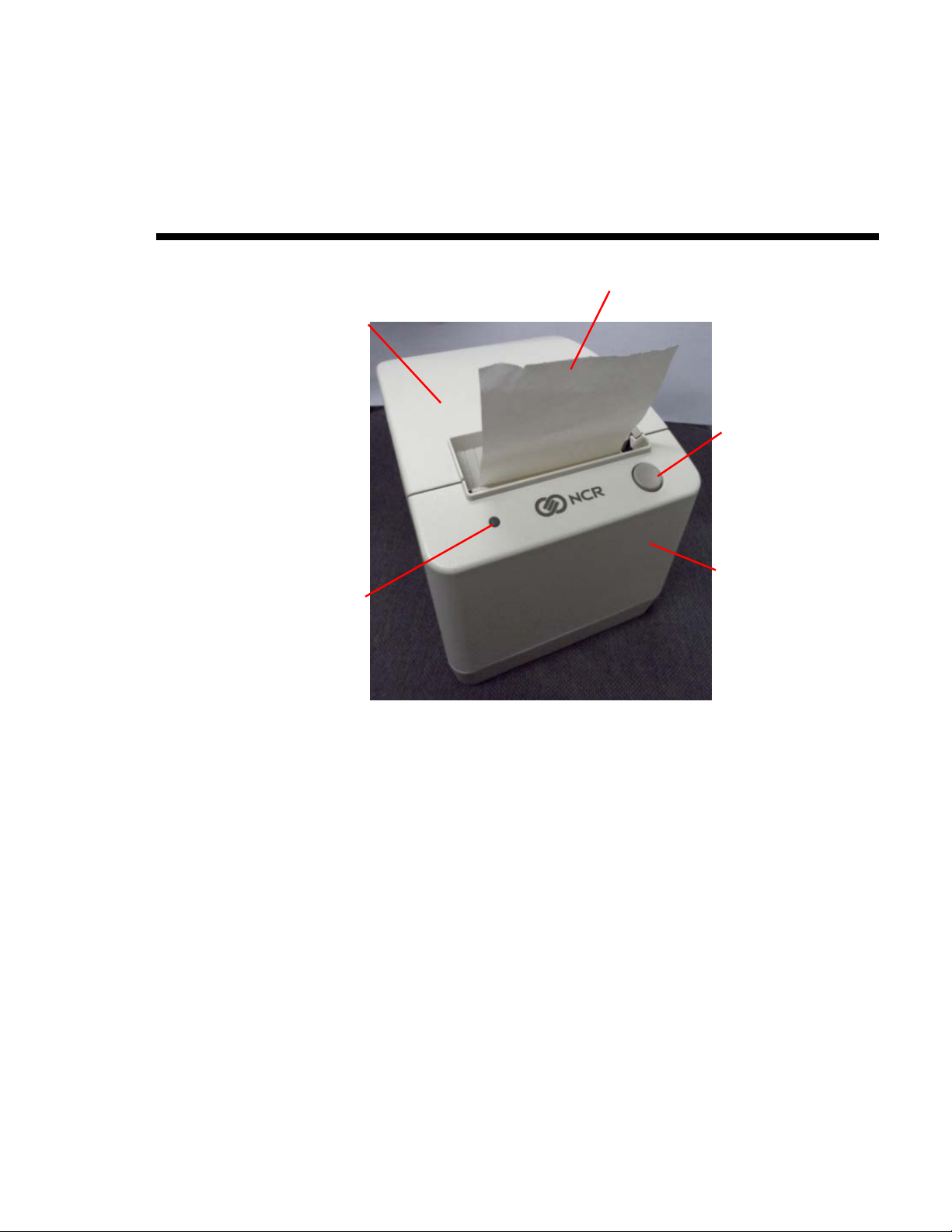
Receipt
Receipt Cover
Paper Feed
Button
Top Cover
LED
The 7197 Series II printer is a fast, quiet, relatively small and very reliable
multiple- function printer. It prints receipts and two color printing.
The industry-standard RS-232C communication interface allows the 7197 Series II
to be connected to any host computer that uses RS-232C or USB communication
interface. 7197 Series II Series II also available in Ethernet communication
interface.
June 2011
1

7197 Series II Owner’s Manual Chapter 1: About the 7197 Series II Printer
Features
The 7197 Series II printer comes with several features and options.
Receipt Station
Thermal printing
Standard pitch (host selectable): 15.2 characters per inch, 44 columns
Compressed pitch (host selectable): 19.0 characters per inch, 56 columns
ECO feature
Resident bar codes
- Code 39
- Code 93
- Code 128
- UPC-A
- UPC-E
- JAN8 (EAN)
- JAN13 (EAN)
- Interleaved 2 of 5
- Codabar
- PDF417
- GS1 DataBar Omnidirectional
- GS1 DataBar Truncated
- GS1 DataBar Stacked
- GS1 DataBar Stacked Omnidirectional
- GS1 DataBar Limited
- GS1 DataBar Expanded
- GS1 DataBar Expanded Stacked
QR Barcode
Drop-in paper loading requiring no spindle or threading paper
Paper low indicator
Paper exhaust
Variety of print modes: double high (receipt station only), double wide, upside down, and
rotated
14 resident single byte character language Code Pages:
1) PC Code Page 437 (US English)
2) PC Code Page 850 (Multilingual)
3) PC Code Page 852 (Slavic)
4) PC Code Page 858 (with Euo symbol)
5) PC Code Page 860 (Portuguese)
6) PC Code Page 862 (Hebrew)
7) PC Code Page 863 (French Canadian)
June 2011
2

7197 Series II Owner’s Manual Chapter 1: About the 7197 Series II Printer
8) PC Code Page 864 (Arabic)
9) PC Code Page 865 (Nordic)
10) PC Code Page 866 (Cyrillic)
11) PC Code Page 874 (Thai)
12) PC Code Page 1252 (Windows Latin #1)
13) PC Code Page 1256 (Windows Arabic)
14) PC Code Page Katakana
Unicode (UTF-16) support
Space Page
Maximum 384K flash memory for downloaded character sets and bit-mapped graphics (such as
logos)
128K RAM for download bit-mapped graphics (such as logos)
General Features
Knife
Cover open sensors
Industry standard RS-232C and USB communication interface, also available with Ethernet
communication interface
One cash drawer connector (supports 2 cash drawers)
History EEROM for custom settings
Audible tone (controlled by application)
ENERGY STAR qualified
Thermal head failure detection
ECO (Paper reduction, Power reduction)
Options
Thermal Print Head
Note: The 7197 Series II does not use a paper journal. The journal is kept electronically by
the host computer.
Remote power supply
Communication cables
4 optional double byte character language Code Pages:
1) PC Code Page 932 (Japanese)
2) PC Code Page 936 (Simplified Chinese)
3) PC Code Page 949 (Korean)
4) PC Code Page 950 (Big5)
Wall mount kit
The 7197 Series II Receipt Station uses a thermal print head for printing receipts,
and is extremely fast and quiet. Since it uses heat to print directly on paper, there
is no cassette or ribbon to change, eliminating soiled fingers and paper dust.
June 2011
3

7197 Series II Owner’s Manual Chapter 1: About the 7197 Series II Printer
There is no regularly scheduled maintenance for the print head and it does not
need to be regularly cleaned. However, if it does appear dirty, wipe it with cotton
swabs and rubbing alcohol. If spotty or light printing problems persist after the
thermal print head has been cleaned, see “Chapter 3: Solving Problems” for more
information.
Note: The thermal print head does not normally require cleaning if the
recommended paper is used. If non-recommended paper has been used for an
extended period of time, cleaning the print head with cotton swabs and rubbing
alcohol will not be of much benefit. See “Ordering Receipt Paper” on the next
page for the recommended paper.
The print head is designed for a very long life, but it may be replaced if needed.
Only a trained service representative may replace the print head. See “Chapter 3:
Solving Problems” to determine if the print head needs to be replaced.
June 2011
4

7197 Series II Owner’s Manual Chapter 1: About the 7197 Series II Printer
Ordering Paper and Supplies
Thermal receipt paper, ribbon cassettes, and forms can be ordered.
Documentation is also available.
Ordering Thermal Receipt Paper
The 7197 Series II requires NCR qualified thermal paper to be used on the thermal receipt
print station to insure proper operation of the printer. In addition the paper rolls must be
have the following dimension.
Diameter Length Width
80 mm max. (3.15 in.) 83 meters (273 ft.) 80 mm ± .5 mm (3.15 ± .008 in.)
The paper must not be attached at the core. Otherwise the receipt station will be damaged
when the paper is exhausted.
Paper grades available from NCR
Paper Stock Paper Grade Description
856911 Economy (for text printing)
856966 Standard Sensitivity (for text and simple graphics)
878559 High Sensitivity (for text, bar codes & detailed graphics)
856380
856461 Red/Black
856458 Blue/Black
The paper must not be attached at the core. Otherwise the receipt station will be damaged
when the paper is exhausted.
To order thermal receipt paper, contact your sales representative or order from NCR at the
following address or toll free number:
For improved archiveability and added resistance to
incompatible substances
NCR
Media Products Division
9995 Washington Church Road
Miamisburg, OH 45342
Voice: 1(800)543-8130 (toll free), or local listing of The NCR Media Products
sales office
June 2011
5

7197 Series II Owner’s Manual Chapter 1: About the 7197 Series II Printer
Ordering Other Supplies
Contact your sales representative to order the supplies listed in the table.
Item Type Number
Power supply with attached cable to
printer and U.S. power supply cord
Power supply ( w/o power cord) 75 Watt Power Supply 7167-K411-V001
Power supply cord (to outlet) United States
RS-232C Communication Cables
9-pin to 9-pin
9-pin to 9-pin
DC Plus Power Cables
DC Power from NCR POS Terminal
DC Power from NCR POS Terminal
USB Communication Cables
USB Type A to Type B Connector
USB Type A to Type B Connector
USB Plus Power Cables
USB Plus Power to Type B Connector
USB Plus Power to Type B Connector
Cash Drawer 2189 2189-K002-V001
Cash Drawer Cable Y Cable 1416-C372-0006
75 Watt Power Supply 7167-K411-V001
1406-C325-0030
International (no plug)
United Kingdom
S.E.V.
Australia
International (with plug)
0.7 meters
3.0 meters (9.8 feet)
1.0 Meters
4.0 Meters
2.0 Meters
4.0 Meters
1.0 Meters
4.0 Meters
1416-C319-0030
1416-C321-0030
1416-C320-0030
1416-C322-0030
1416-C323-0030
1416-C359-0007
1416-C266-0040
1416-C712-0010
1416-C712-0040
1416-C528-0010
1416-C528-0040
1416-C713-0010
1416-C713-0040
(Switchable for
Drawer 1 or Drawer
2)
Ordering Documentation
Contact your sales representative to obtain the following documentation:
7197 Series II Receipt Printer: Parts Identification Manual (B005-000-2070)
7197 Series II Receipt Printer: Service Manual (B005-000-2069)
(includes Troubleshooting Guide)
7197 Series II Receipt Printer: Owners Manual (B0005-0000-2068)
June 2011
6

7197 Series II Owner’s Manual Chapter 1: About the 7197 Series II Printer
Cleaning the Printer
Cleaning the Cabinet
The external cabinet materials and finish are durable and resistant to these items:
Cleaning solutions
Lubricants
Fuels
Cooking oils
Ultraviolet light
There is no scheduled maintenance required for the 7197 Series II.
Clean the cabinet as needed to remove dust and finger marks. Use any household cleaner
designed for plastics, but test it first on a small unseen area. If the receipt bucket is dirty,
wipe it with a clean, damp cloth.
June 2011
7

7197 Series II Owner’s Manual Chapter 1: About the 7197 Series II Printer
Cleaning the Thermal Print Head
Caution: Do not spray or try to clean the thermal print head or the inside of the printer
with any kind of cleaner as this may damage the thermal print head and electronics.
If the thermal print head appears dirty, wipe it with cotton swabs and isoprophl alcohol.
If spotty or light printing problems persist after the thermal print head has been cleaned,
see “Chapter 3: Solving Problems” for more information.
Note: The thermal print head does not normally require cleaning if the recommended
paper grades are used. If non-recommended paper has been used for an extended period
of time, cleaning the print head with cotton swabs and rubbing alcohol will not be of much
benefit. See “Ordering Paper and Supplies” earlier in this manual for recommended paper.
June 2011
8

7197 Series II Owner’s Manual Chapter 2: Setting Up and Using the Printer
Chapter 2: Setting Up and Using the Printer
What Is in the Box?
The following items are packed in the shipping box:
Printer enclosed in a plastic bag and foam pack
Thermal receipt paper roll
These items may be ordered as options from NCR and will be shipped separately:
Communication cable (from host computer to printer)
DC Power Cable
Remote Power Supply
Cash drawer with cables (may be ordered from other equipment suppliers: see “Ordering
Other Supplies” in chapter 1)
Wall Mount kit
8 September 2011
7197 Series II Owner’s Manual Chapter 2: Setting Up and Using the Printer
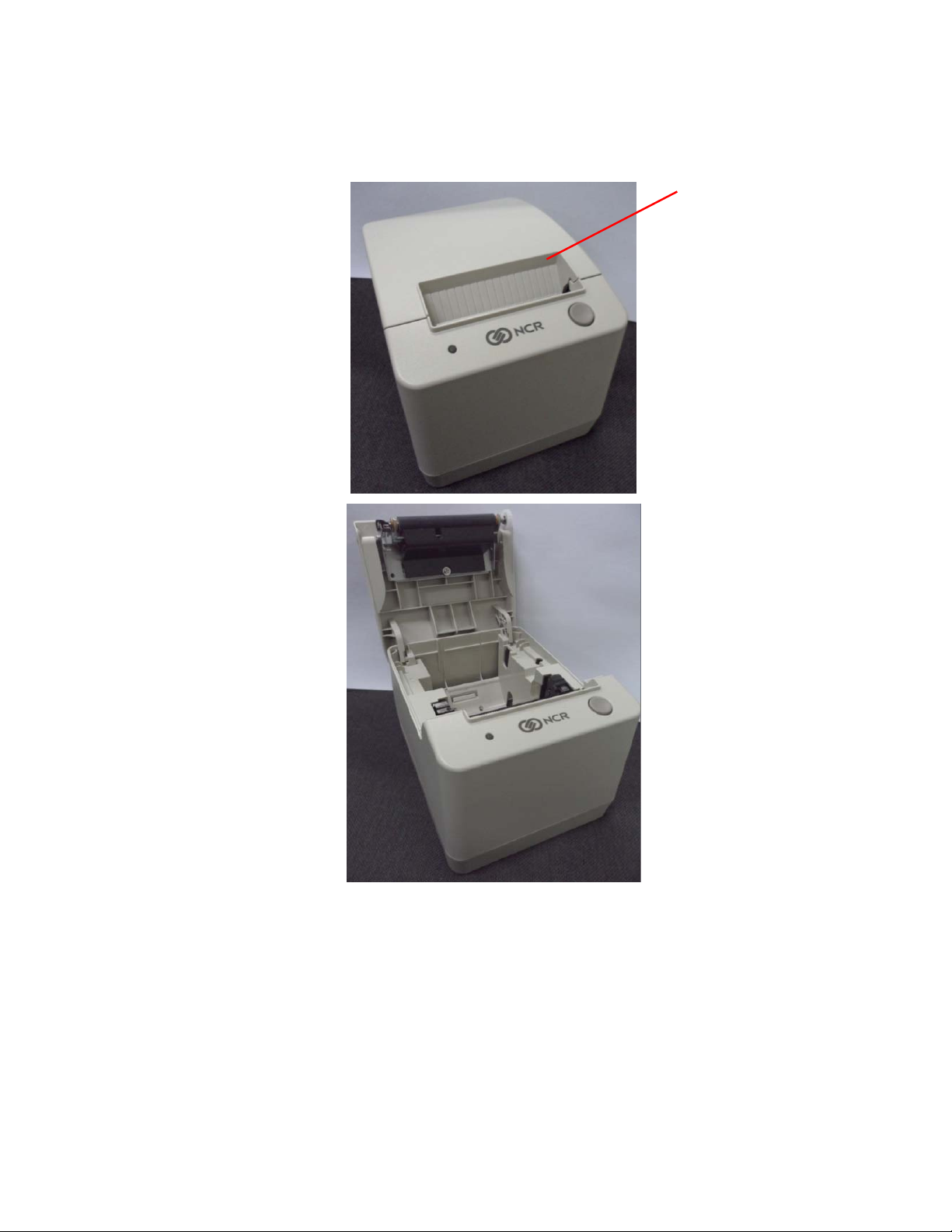
Removing the Packing Material
1. Remove the printer from the foam pack and plastic bag.
Receipt
Cover
2. Remove the receipt paper roll from the foam packing material.
3. Save all packing materials for future storing, moving, or shipping the printer.
9 September 2011
7197 Series II Owner’s Manual Chapter 2: Setting Up and Using the Printer
Repacking the Printer
Review the illustrations on the previous two pages to pack the printer.
1. Place receipt paper between the receipt cover and the print head for protection.
2. Place the printer in the plastic bag and foam pack, place the packed printer in the box,
and secure the box with packing tape.
3. If you are sending the printer to NCR for repair, call your NCR-authorized service
representative for instructions on where to send the printer.
Be prepared to answer questions concerning shipping and billing.
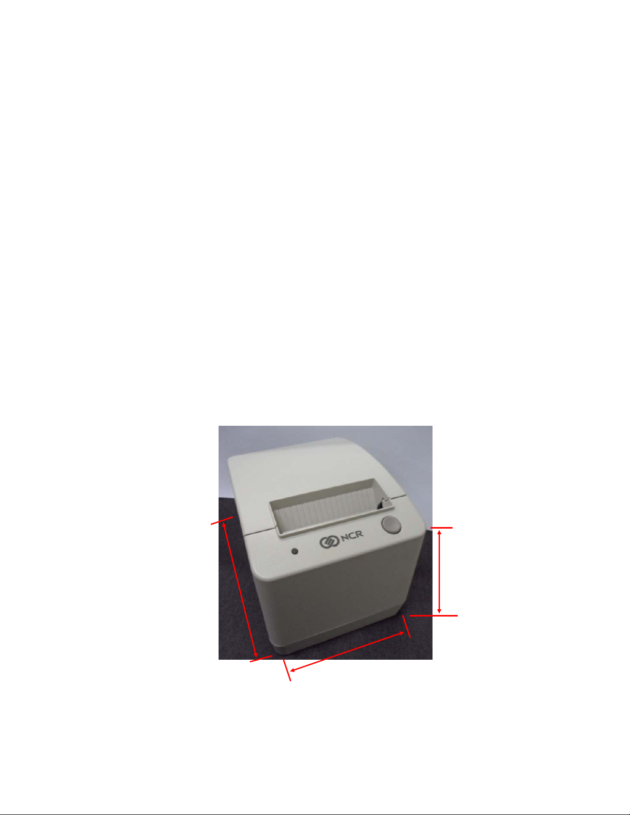
Choosing a Location
The 7197 Series II printer takes up relatively little counter space and may be set on or near the
host computer. Make sure there is enough room to open the receipt cover to change the paper.
The illustration shows the actual dimensions of the printer but leaves several inches around
the printer for connecting and accessing the cables.
144.90 mm
(5.70 in.)
186.70 mm
(7.35 in.)
145.50 mm
(5.80 in.)
10 September 2011
7197 Series II Owner’s Manual Chapter 2: Setting Up and Using the Printer
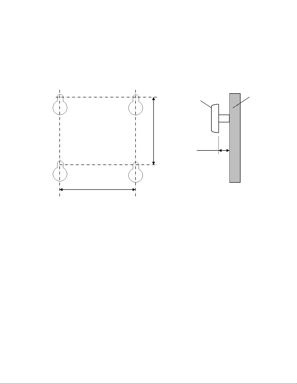
Wall mounted
The 7197 Series II Series II printer may be mounted on a vertical wall with Wall Mount Kit
(Option). Make sure there is enough room to open the receipt cover to change the paper. Mount the
screws on the wall using the following recommended mount dimensions. Use a #8 wood screw
which is to be securely fastened to a wall stud or using a “Molly” fastener (not provided).
121mm (4.75 in.)
Screw
3.5 ~ 4 mm
(.138 – .160 in.)
Wall
128 mm (5.04 in..)
11 September 2011
7197 Series II Owner’s Manual Chapter 2: Setting Up and Using the Printer
n
r
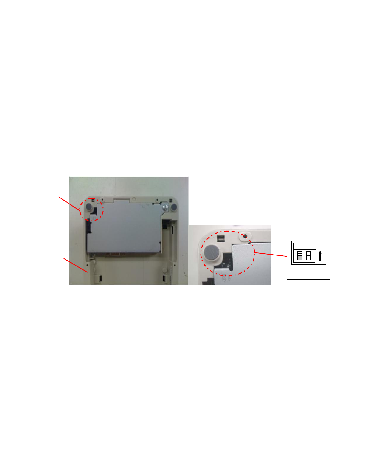
Setting Switches
The DIP switches, located at the back of the printer, are used for two purposes:
To set variables for several printer functions (see the sections for the various printer
functions in “Level 1 Diagnostics” in “Chapter 4: Diagnostics” for Setting Up the
Printer)
To perform diagnostic tests (see the sections for the various diagnostic tests in “Level
1 Diagnostics” in “Chapter 4: Diagnostics” for Setting Up the Printer)
Caution: The DIP switches are set at the factory to predetermined settings and should
not be changed unless to change parameters or to reflash the firmware.
DIP
Switch
Bottom
Cover
Bottom of Printe
Switch 1 is shown in
the OFF positio
Note: Switch 1 is shown in the Off position for reference.
Use a paper clip or other pointed object to set the switches.
1. Set the switches to the desired settings shown in the table.
2. Reset the printer by disconnecting and reconnecting the power to the
printer.
12 September 2011

7197 Series II Owner’s Manual Chapter 2: Setting Up and Using the Printer
Resetting the Printer
The printer is reset by disconnecting/reconnecting the DC power.
Connecting the Cables
There are three different types of cables that connect to the printer:
Power supply cable supplying power from the power supply
Communication cable (RS-232 or USB) connecting the printer to the host computer
Cash drawer cable connecting the printer to one or two cash drawers
Caution: Disconnect the power before connecting the cables. Always connect the
communication cable and cash drawer cables before connecting power to the power
supply. Always disconnect power to the power supply before disconnecting the
communication and cash drawer cables.
Follow these steps to connect the cables. See the illustration on the next page.
1. Unplug the power supply from its power source.
2. Connect the power and communication cables to their respective connectors under
the printer as shown in the illustration.
For the RS232 Cable, be sure to screw the communication cable to the communication
connector.
3. Route the cables through the cable strain relief on the bottom of the printer, then
through the two slots in the cable access cover as shown in the illustration.
4. Connect the communication cable to the appropriate host computer connector.
5. Connect the cash drawer cable to the printer and cash drawer.
The connectors is a standard phone jack located at the rear of the printer.
6. Plug the power cord into the power supply for remote power supply installation,
then plug the power supply into an outlet.
At this point, the printer receives power. If the On Line LED (green) is on, the printer is
on-line. Otherwise, the printer is off-line.
13 September 2011
7197 Series II Owner’s Manual Chapter 2: Setting Up and Using the Printer
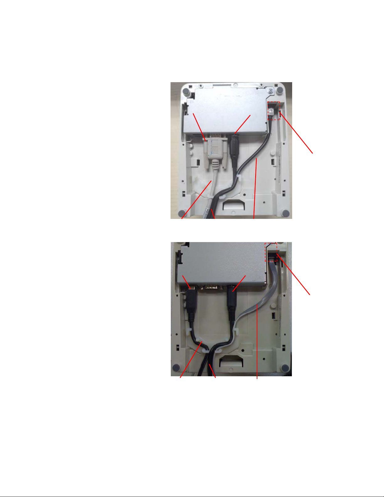
7. For Host powered installation plug the DC cable into the POS terminal.
RS-232 Cable Connection
Communication
Connector
Communication
Cable
Power
Cable
Power
Connector
Cash Drawer
Cable
Cash Drawer
Connector
USB Cable Connection
USB
Connector
Power
Connector
Cash Drawer
Connector
USB Cable
Power
Cable
Cash Drawer
Cable
Bottom of the Printer
14 September 2011
7197 Series II Owner’s Manual Chapter 2: Setting Up and Using the Printer
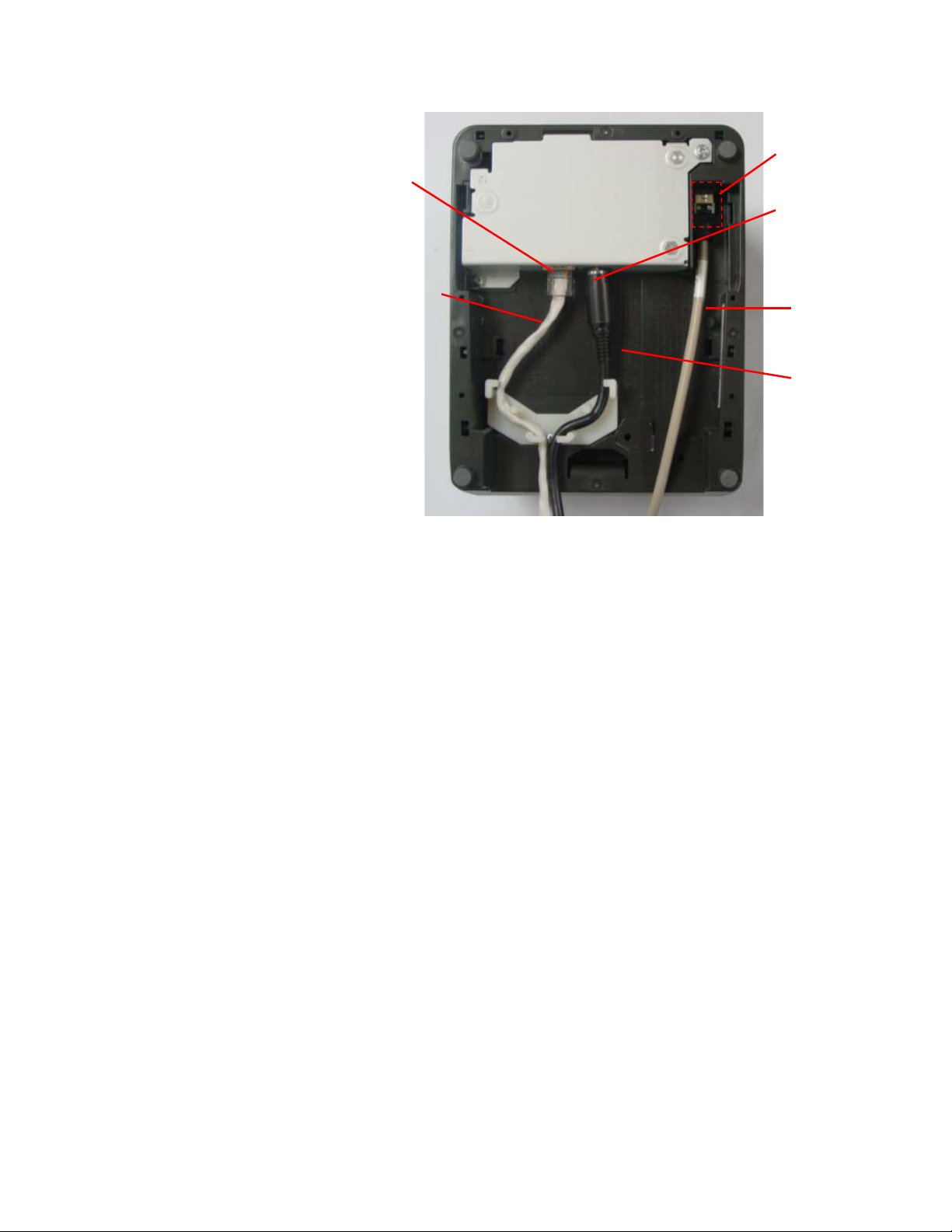
t
r
r
Ethernet Cable Connection (Ethernet model)
Cash
Drawer
Etherne
Connecto
Power
Connecto
Ethernet
Cable
Cash Drawer
Cable
Power
Cable
Bottom of the Printer
15 September 2011

7197 Series II Owner’s Manual Chapter 2: Setting Up and Using the Printer
About the Universal Serial Bus
The Universal Serial Bus (USB) is a peripheral bus for personal computers that was first
released in January 1996. Since that time, virtually all Intel Architecture personal
computers have the hardware to support USB, and a large number of computers exist
that have both the hardware and software support required to interface with USB
peripherals.
Advantages of USB connections
USB has a number of advantages over legacy connection schemes (e.g., serial RS-232).
These advantages include:
High Speed: up to 12 MB/second for high-speed devices.
Plug and Play: Devices are automatically recognized and configured at installation.
Hot plug: Bus supports installation and removal of devices with the power applied.
Up to 127 devices: One host can support up to 127 devices with the use of hubs.
“Free ports”: Most PC architecture machines contain two USB ports in the base
hardware.
These advantages have become attractive to the POS industry for a couple of reasons.
Additional POS devices. Some POS systems are required to host more peripherals than
can be supported by two RS-232 ports typical in a platform. With the addition of one (or
two) USB connectors, the platform can now support the additional devices that had
previously required a serial port expander card.
Higher bandwidths. New devices coming into use have bandwidth requirements that
are higher than the bandwidth that can be supported on legacy interfaces. These devices
include image scanners and printers. As the speed and capability of POS printers
increases, the performance of the printer in an application can become limited by the
speed of the communications interface. USB provides ample bandwidth to support
current and future POS printer requirements.
Advantages of the NCR USB Solution
NCR has eliminated any cost associated with porting applications to USB by
implementing a USB solution that simulates standard serial communications in Windows
XP. Application developers need only redirect their software to the virtual serial ports
created by the NCR USB solution to use the printer.
16 September 2011
 Loading...