

NCR 7197 Owner's Manual
NCR 7197 Thermal Receipt
Printer
Release 1.0
Owner's Manual
B005-000-1409
Revision B
March, 2002

The product described in this book is a licensed product of NCR Corporation.
NCR is the registered trademark of NCR Corporation. Other trademarks and registered trademarks are the property of their
respective holders.
It is the policy of NCR Corporation (NCR) to improve products as new technology, components, software, and firmware
become available. NCR, therefore, reserves the right to change specifications without prior notice.
All features, functions, and operations described herein may not be marketed by NCR in all parts of the world. In some
instances, photographs are of equipment prototypes. Therefore, before using this document, consult with your NCR
representative or NCR office for information that is applicable and current.
To maintain the quality of our publications, we need your comments on the accuracy, clarity, organization, and value of this
book.
Address correspondence to:
Retail Systems Group−Atlanta
NCR Corporation
2651 Satellite Blvd.
Duluth, GA 30136
Copyright © 2002
By NCR Corporation
Dayton, Ohio U.S.A.
All Rights Reserved
ii

Important Information to the User
In order to ensure compliance with the Product Safety, FCC and CE marking requirements, you must use the power supply,
power cord, and interface cable which were shipped with this product or which meet the following parameters:
Power Supply
UL Listed (QQGQ), Class 2 power supply with SELV (Secondary Extra Low Voltage), non-energy hazard output, limited
energy source, input rated 100-240 Vac, 1.5/0.8 A, 50/60 Hz, output rated 24 Vdc, 2.3 A. or 3.15A
Use of this product with a power supply other than the NCR power supply will require you to test this power supply and
NCR printer for FCC and CE mark certification.
Interface Cable
A shielded (360 degree) interface cable must be used with this product. The shield must be connected to the frame or earth
ground connection or earth ground reference at EACH end of the cable.
Use of a cable other than described here will require that you test this cable with the NCR printer and your system for FCC
and CE mark certification.
Power Cord
A UL listed, detachable power cord must be used for this product. For applications where the power supply module may be
mounted on the floor, a power cord with Type SJT marking must be used. For applications outside the US, power cords which
meet the particular country’s certification and application requirements should be used.
Use of a power cord other than described here may result in a violation of safety certifications which are in force in the
country of use.
iii

Federal Communications Commission (FCC)
Radio Frequency Interference Statement
Warning: Changes or modifications to this unit not expressly approved by the party responsible for compliance could void the
user’s authority to operate the equipment.
Note: This equipment has been tested and found to comply with the limits for a Class A digital device, pursuant to Part 15 of
the FCC Rules. These limits are designed to provide reasonable protection against harmful interference when the equipment is
operated in a commercial environment. This equipment generates, uses, and can radiate radio frequency energy and, if not
installed and used in accordance with the instruction manual, may cause harmful interference to radio communications.
Operation of this equipment in a residential area is likely to cause harmful interference in which case the user will be required
to correct the interference at his own expense.
Communication Cables
Shielded communication cables must be used with this unit to ensure compliance with the Class A FCC limits.
Information to User
This equipment must be installed and used in strict accordance with the manufacturer's instructions. However, there is no
guarantee that interference to radio communications will not occur in a particular commercial installation. If this equipment
does cause interference, which can be determined by turning the equipment off and on, the user is encouraged to contact NCR
immediately.
The NCR company is not responsible for any radio or television interference caused by unauthorized modification of this
equipment or the substitution or attachment of connecting cables and equipment other than those specified by NCR. The
correction of interferences caused by such unauthorized modification, substitution or attachment will be the responsibility of
the user.
Industry Canada (IC)
Radio Frequency Interference Statement
This Class A digital apparatus meets all requirements of the Canadian Interference-Causing Equipment Regulations.
Cet appareil numérique de la classe A respecte toutes les exigences du Règlement sur le matériel brouilleur du Canada.
iv

Quick Reference
This Quick Reference will direct you to key areas of the Owner’s Manual. For a complete
listing of topics, consult the Table of Contents or the Index.
Setting Up the Printer .................................................... page 7
Basic requirements for unpacking and installation, connecting the printer, turning it on,
and running the print test.
Running the Data Scope Mode.................................... page 45
Instructions for running the data scope mode.
Troubleshooting ............................................................ page 37
Information on correcting problems with the printer.
v

How to Use this Book
Use this book as a general and technical reference manual and as a guide when replacing
parts on the printer. The service guide is intended as a guide for service representatives,
field engineers, and those who will be installing and learning about the 7197 printer. It can
also be used as a reference for service courses.
See the Quick Reference page, the Contents, or the Index for detailed listings of what is
contained in this book.
Who Should Use this Book?
You must be a trained service representative to service the 7197 Thermal Receipt printer.
How to Obtain More Information
For more information see the following documents:
• 7197 Receipt Printer: Service Manual (B005-000-1410)
• 7197 Receipt Printer: Parts Identification Manual (B005-000-1411)
For this and additional copies of the Owner’s Manual, contact your sales representative.
Revision Record
Issue Date Remarks
A Apr 2002 First printing
B May 2002 Update to reflect first
production configuration.
vi

7197 Owner’s Manual Contents
Contents
Quick Reference ..........................................................................................................v
How to Use this Book.........................................................................................vi
Who Should Use this Book?..............................................................................vi
How to Obtain More Information....................................................................vi
Revision Record .........................................................................................................vi
Contents ......................................................................................................................ix
Chapter 1: About the 7197 Printer ....................................................................................................1
Features and Options .................................................................................................2
Receipt Station......................................................................................................2
General Features..................................................................................................3
Options..................................................................................................................3
Thermal Print Head....................................................................................................3
Ordering Paper and Supplies.................................................................................... 4
Ordering Thermal Receipt Paper.......................................................................4
Ordering Other Supplies ....................................................................................5
Ordering Documentation ...................................................................................5
Cleaning the Printer....................................................................................................6
Cleaning the Cabinet...........................................................................................6
Cleaning the Thermal Print Head .....................................................................6
Chapter 2: Setting Up and Using the Printer ................................................................................... 8
What Is in the Box?..................................................................................................... 8
Removing the Packing Material ........................................................................9
Repacking the Printer........................................................................................ 10
Choosing a Location.................................................................................................10
Setting Switches ........................................................................................................11
Connecting the Cables..............................................................................................12
About the Universal Serial Bus...............................................................................14
Advantages of USB connections......................................................................14
Advantages of the NCR USB Solution............................................................ 14
Checking for USB Support on the Host Computer..............................................15
Host Configuration............................................................................................15
Configuring the Printer............................................................................................ 16
Installing the USB Printer Drivers..........................................................................19
Checking the Installation.........................................................................................29
Configuring Serial Port Number Assignments.....................................................32
Running the Edgeport Utility ..........................................................................32
Serial Port Configuration Methods ................................................................. 33
Uninstalling the Drivers ...................................................................................33
Using the Printer.......................................................................................................35
Loading and Changing the Receipt Paper.............................................................36
Removing the Paper Roll..................................................................................36
March 2002
ix

7197 Owner’s Manual Contents
Loading the Paper Roll .....................................................................................38
Advancing Paper ............................................................................................... 39
Chapter 3: Solving Problems .......................................................................................................... 39
Green LED Does Not Come On/Printer Will Not Print......................................40
Green LED Blinking (Slow) ..................................................................................... 40
Green LED Blinking (Fast)....................................................................................... 40
Receipt Printing is Light or Spotty ......................................................................... 41
Other Serious Problems ...........................................................................................42
Contacting a Service Representative......................................................................42
Chapter 4: Diagnostics ....................................................................................................................44
Level 0 Diagnostics...................................................................................................44
Level 1 Diagnostics...................................................................................................45
Printer Configuration........................................................................................45
Configuring the Printer.....................................................................................46
Communication Interface Modes....................................................................49
Diagnostic Modes .............................................................................................. 51
Emulation/Software Options ..........................................................................53
Hardware Options............................................................................................. 56
Default Code Page.............................................................................................58
EEPROM to Default Settings............................................................................ 60
Level 2 Diagnostics...................................................................................................61
Level 3 Diagnostics...................................................................................................61
Chapter 5: Communication ............................................................................................................. 60
Communication Overview......................................................................................60
Interface...............................................................................................................60
Sending Commands.......................................................................................... 60
RS-232C Interface......................................................................................................61
Print Speed and Timing....................................................................................61
XON/XOFF Protocol......................................................................................... 62
DTR/DSR Protocol............................................................................................62
RS-232C Technical Specifications....................................................................62
Setting Extra RS-232C Options ........................................................................65
Chapter 6: Commands..................................................................................................................... 67
Command Conventions...........................................................................................67
Introduction...............................................................................................................67
List of Commands and Location.............................................................................67
By Command Code ........................................................................................... 68
By Function......................................................................................................... 72
Printer Function Commands............................................................................ 72
Vertical Positioning and Print.......................................................................... 72
Horizontal Positioning Commands ................................................................73
Print Characteristic Commands.......................................................................73
Graphics Commands......................................................................................... 74
Status Commands.............................................................................................. 74
x
March 2002

7197 Owner’s Manual Contents
Real Time Commands....................................................................................... 74
Auto Status Back Commands...........................................................................75
Barcode Commands ..........................................................................................75
Page Mode Commands..................................................................................... 75
Macro Commands .............................................................................................75
User Data Storage Commands......................................................................... 76
Asian Character Commands............................................................................76
Flash Download Commands............................................................................ 76
Comparison Chart ............................................................................................. 77
Command Descriptions ........................................................................................... 79
Printer Function Commands............................................................................ 80
Vertical Positioning and Print Commands ....................................................86
Horizontal Positioning Commands ................................................................92
Print Characteristic Commands.....................................................................100
Graphics Commands....................................................................................... 116
Status Commands............................................................................................126
Real Time Commands..................................................................................... 137
Auto Status Back Commands.........................................................................143
Bar Code Commands ...................................................................................... 146
Page Mode Commands................................................................................... 152
Macro Commands ...........................................................................................160
User Data Storage Commands....................................................................... 162
Asian Character Commands.......................................................................... 170
Flash Download Commands.......................................................................... 174
Appendix A: Specifications.............................................................................................................67
Printing Specifications..............................................................................................67
Power Requirements ................................................................................................ 68
Environmental Conditions ...................................................................................... 68
Reliability...................................................................................................................68
Dimensions and Weight...........................................................................................68
Density of Receipt Print Lines................................................................................. 69
Duty Cycle Restrictions (Printing Solid Blocks) ................................................... 69
Appendix B: Print Characteristics.................................................................................................. 71
Character Size............................................................................................................ 71
Receipt Station....................................................................................................71
Print Zones................................................................................................................. 72
Receipt Station....................................................................................................72
Character Sets............................................................................................................74
Index...........................................................................................................................79
March 2002
xi

7197 Owner’s Manual Contents
xii
March 2002
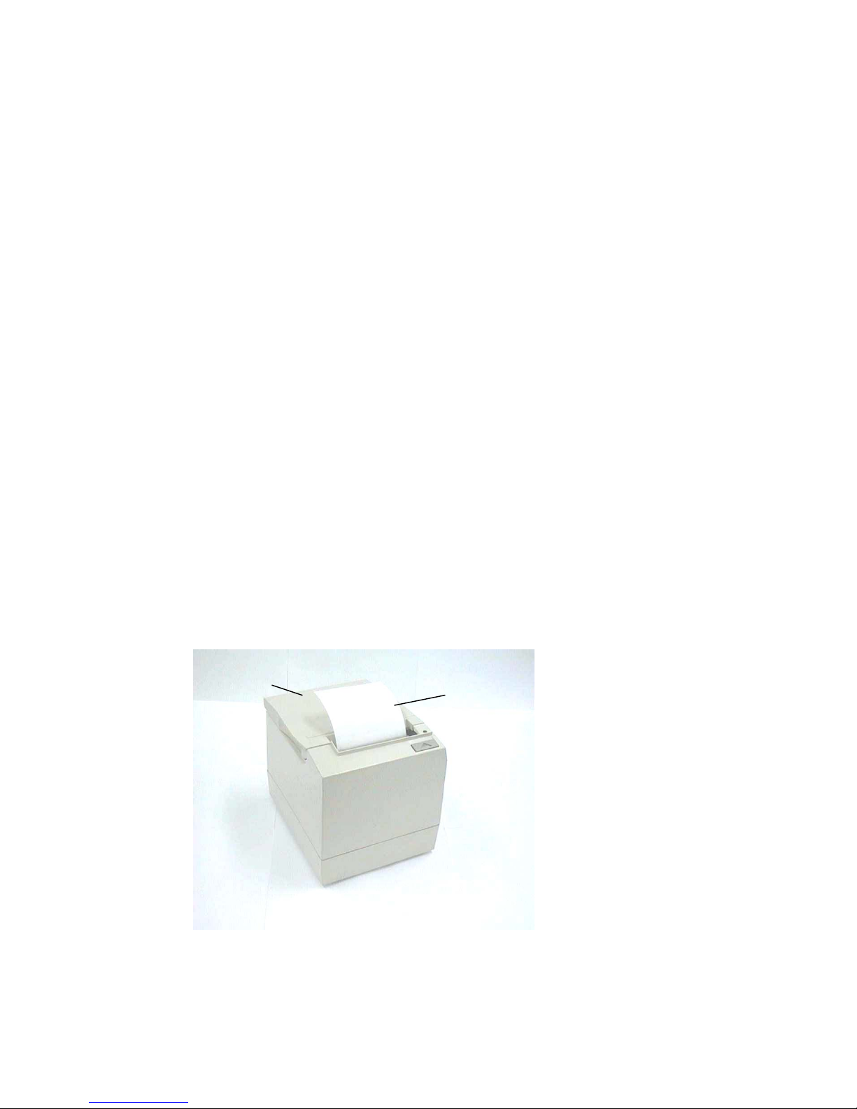
7197 Owner’s Manual Chapter 1: About the 7197 Printer
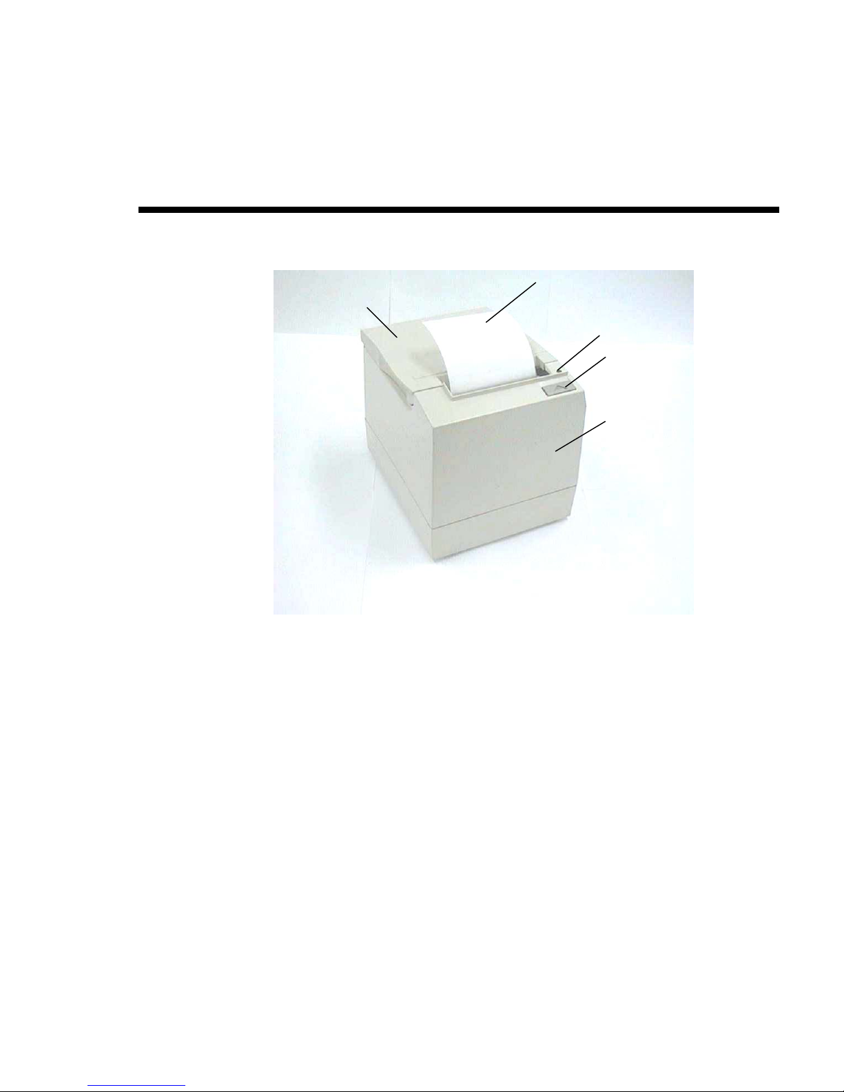
Chapter 1: About the 7197 Printer
Receipt Cover
Receipt
LED
Paper Feed
Button
Top Cover
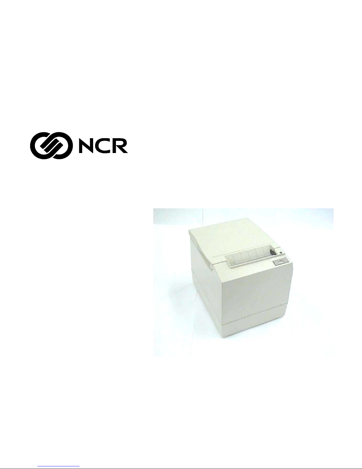
The 7197 printer is a fast, quiet, relatively small and very reliable multiple-
function printer. It prints receipts and two color printing.
The industry-standard RS-232C communication interface allows the 7197 to be
connected to any host computer that uses RS-232C or USB communication
interface.
March 2002
1

7197 Owner’s Manual Chapter 1: About the 7197 Printer
Features and Options
The 7197 printer comes with several features and options.
Receipt Station
• Thermal printing
• Standard pitch (host selectable): 15.2 characters per inch, 44 columns
• Compressed pitch (host selectable): 19.0 characters per inch, 56 columns
• Resident bar codes
• Code 39
• Code 93
• Code 128
• UPC-A
• UPC-E
• JAN8 (EAN)
• JAN13 (EAN)
• Interleaved 2 of 5
• Codabar
• PDF417
• Drop-in paper loading requiring no spindle or threading paper
• Paper low indicator
• Paper exhaust indicator
• Variety of print modes: double high, double wide, upside down, and rotated
• 14 resident character language Code Pages:
• PC Code Page 437 (US English)
• PC Code Page 850 (Multilingual)
• PC Code Page 852 (Slavic)
• PC Code Page 858 (with Euo symbol)
• PC Code Page 860 (Portuguese)
• PC Code Page 862 (Hebrew)
• PC Code Page 863 (French Canadian)
• PC Code Page 864 (Arabic)
• PC Code Page 865 (Nordic)
• PC Code Page 866 (Cyrillic)
• PC Code Page 1252 (Windows Latin #1)
• PC Code Page Katakana
• PC Code Page 874 (Thai)
• Space Page
• 16K RAM for downloaded character sets or bit-mapped graphics (such as
2
logos)
March 2002

7197 Owner’s Manual Chapter 1: About the 7197 Printer
General Features
• Knife
• Cover open sensors
• One cash drawer connector (supports 2 cash drawers)
• Industry standard RS-232C and USB communication interface
• History EEROM for custom settings
• Audible tone (controlled by application)
Note: The 7197 does not have a paper journal. The journal is kept electronically by
the host computer.
Options
• Remote power supply
• Communication cables
Thermal Print Head
The 7197 Receipt Station uses a thermal print head for printing receipts, and is
extremely fast and quiet. Since it uses heat to print directly on paper, there is no
cassette or ribbon to change, eliminating soiled fingers and paper dust.
There is no regularly scheduled maintenance for the print head and it does not
need to be regularly cleaned. However, if it does appear dirty, wipe it with cotton
swabs and rubbing alcohol. If spotty or light printing problems persist after the
thermal print head has been cleaned, see “Chapter 3: Solving Problems” for more
information.
Note: The thermal print head does not normally require cleaning if the
recommended paper is used. If non-recommended paper has been used for an
extended period of time, cleaning the print head with cotton swabs and rubbing
alcohol will not be of much benefit. See “Ordering Receipt Paper” on the next
page for the recommended paper.
The print head is designed for a very long life, but it may be replaced if needed.
Only a trained service representative may replace the print head. See “Chapter 3:
Solving Problems” to determine if the print head needs to be replaced.
March 2002
3

7197 Owner’s Manual Chapter 1: About the 7197 Printer
Ordering Paper and Supplies
Thermal receipt paper, ribbon cassettes, and forms can be ordered.
Documentation is also available.
Ordering Thermal Receipt Paper
The 7197 requires NCR qualified thermal paper to be used on the thermal receipt print
station to insure proper operation of the printer. In addition the paper rolls must be have
the following dimension.
Diameter Length Width
80 mm max. (3.15 in.) 83 meters (273 ft.) 80 mm ± .5 mm (3.15 ± .008 in.)
The paper must not be attached at the core. Otherwise the receipt station will be damaged
when the paper is exhausted.
Paper grades available from NCR
Paper Stock Paper Grade Description
856911 Economy (for text printing)
856966 Standard Sensitivity (for text and simple graphics)
878559 High Sensitivity (for text, bar codes & detailed graphics)
856380
Two Color
The paper must not be attached at the core. Otherwise the receipt station will be damaged
when the paper is exhausted.
To order thermal receipt paper, contact your sales representative or order from NCR at the
following address or toll free number:
For improved archiveability and added resistance to
incompatible substances
Please contact your local SMD sales representation for more
detail
NCR
Media Products Division
9995 Washington Church Road
Miamisburg, OH 45342
Voice: 1(800)543-8130 (toll free), or local listing of The NCR Media Products
sales office
4
March 2002

7197 Owner’s Manual Chapter 1: About the 7197 Printer
Ordering Other Supplies
Contact your sales representative to order the supplies listed in the table.
Item Type Number
Power supply with attached cable to
printer and U.S. power supply cord
Power supply ( w/o power cord) 75 Watt Power Supply 7167-K302-V001
Power supply cord (to outlet) United States
RS-232C Communication Cables
9-pin to 9-pin
9-pin to 9-pin
DC Plus Power Cables
DC Power from NCR POS Terminal
DC Power from NCR POS Terminal
USB Communication Cables
USB Type A to Type B Connector
USB Type A to Type B Connector
USB Plus Power Cables
USB Plus Power to Type B Connector
USB Plus Power to Type B Connector
Cash Drawer 2189 2189-K002-V001
Cash Drawer Cable Y Cable 1416-C372-0006
75 Watt Power Supply 7167-K331-V001
1406-C325-0030
International (no plug)
United Kingdom
S.E.V.
Australia
International (with plug)
0.7 meters
3.0 meters (9.8 feet)
1.0 Meters
4.0 Meters
2.0 Meters
4.0 Meters
1.0 Meters
4.0 Meters
1416-C319-0030
1416-C321-0030
1416-C320-0030
1416-C322-0030
1416-C323-0030
1416-C359-0007
1416-C266-0040
1416-C712-0010
1416-C712-0040
1416-C528-0010
1416-C528-0040
1416-C713-0010
1416-C713-0040
(Switchable for
Drawer 1 or Drawer
2)
Ordering Documentation
Contact your sales representative to obtain the following documentation:
• 7197 Receipt Printer: Parts Identification Manual (B005-0000-1411)
• 7197 Receipt Printer: Service Manual (B0005-0000-1410)
• 7197 Receipt Printer: Owners Manual (B0005-0000-1409)
(includes Troubleshooting Guide)
March 2002
5

7197 Owner’s Manual Chapter 1: About the 7197 Printer
Cleaning the Printer
Cleaning the Cabinet
The external cabinet materials and finish are durable and resistant to these items:
• Cleaning solutions
• Lubricants
• Fuels
• Cooking oils
• Ultraviolet light
There is no scheduled maintenance required for the 7197.
Clean the cabinet as needed to remove dust and finger marks. Use any household
cleaner designed for plastics, but test it first on a small unseen area. If the receipt
bucket is dirty, wipe it with a clean, damp cloth.
Cleaning the Thermal Print Head
Caution: Do not spray or try to clean the thermal print head or the inside of the
printer with any kind of cleaner as this may damage the thermal print head and
electronics.
If the thermal print head appears dirty, wipe it with cotton swabs and isoprophl
alcohol.
If spotty or light printing problems persist after the thermal print head has been
cleaned, see “Chapter 3: Solving Problems” for more information.
Note: The thermal print head does not normally require cleaning if the
recommended paper grades are used. If non-recommended paper has been used
for an extended period of time, cleaning the print head with cotton swabs and
rubbing alcohol will not be of much benefit. See “Ordering Paper and Supplies”
earlier in this manual for recommended paper.
6
March 2002

7197 Owner’s Manual Chapter 2: Setting Up and Using the Printer
Chapter 2: Setting Up and Using the Printer
What Is in the Box?
The following items are packed in the shipping box:
• Printer enclosed in a plastic bag and foam pack
• Thermal receipt paper roll
These items may be ordered as options from NCR and will be shipped separately:
• Communication cable (from host computer to printer)
• DC Power Cable
• Remote Power Supply
• Cash drawer with cables (may be ordered from other equipment suppliers: see “Ordering
Other Supplies” in chapter 1)
8 March 2002
7197 Owner’s Manual Chapter 2: Setting Up and Using the Printer
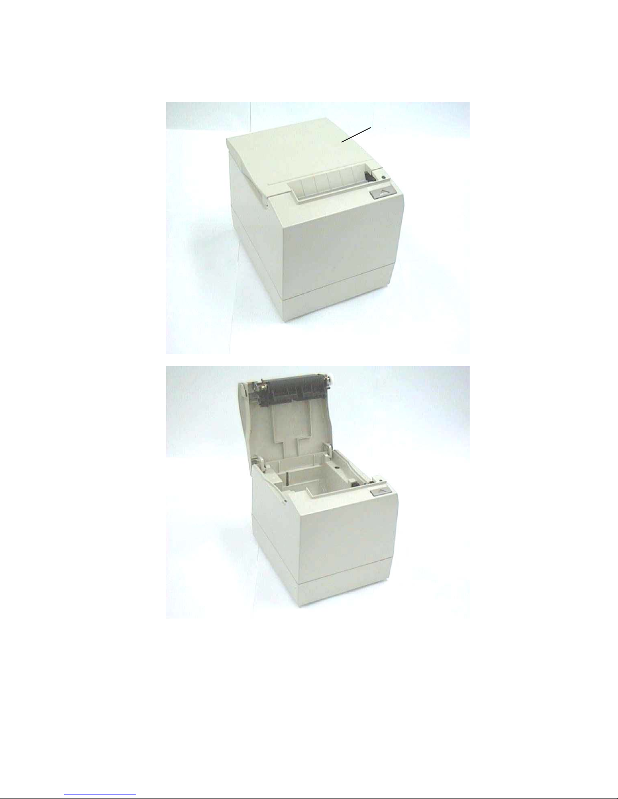
Removing the Packing Material
Receipt
Cover
1. Remove the printer from the foam pack and plastic bag.
2. Remove the receipt paper roll and cables from the foam packing material.
3. Save all packing materials for future storing, moving, or shipping the printer.
Note: If the printer is wall mounted the paper low switch must be disable.
9 March 2002
7197 Owner’s Manual Chapter 2: Setting Up and Using the Printer
Repacking the Printer
Review the illustrations on the previous two pages to pack the printer.
1. Place receipt paper between the receipt cover and the print head for protection.
2. Place the printer in the plastic bag and foam pack, place the packed printer in the
box, and secure the box with packing tape.
3. If you are sending the printer to NCR for repair, call your NCR-authorized service
representative for instructions on where to send the printer.
Be prepared to answer questions concerning shipping and billing.
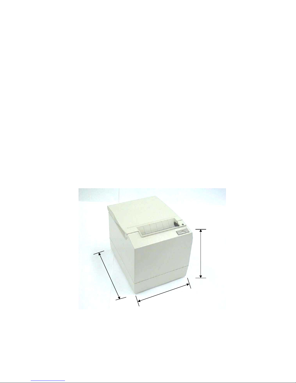
Choosing a Location
The 7197 printer takes up relatively little counter space and may be set on or near the
host computer. Make sure there is enough room to open the receipt cover to change the
paper. The illustration shows the actual dimensions of the printer, but leave several
inches around the printer for connecting and accessing the cables.
183.50 mm
(7.30 in.)
10 March 2002
155.50 mm
(6.20 in.)
145.50 mm
(5.80 in.)
7197 Owner’s Manual Chapter 2: Setting Up and Using the Printer
n
r
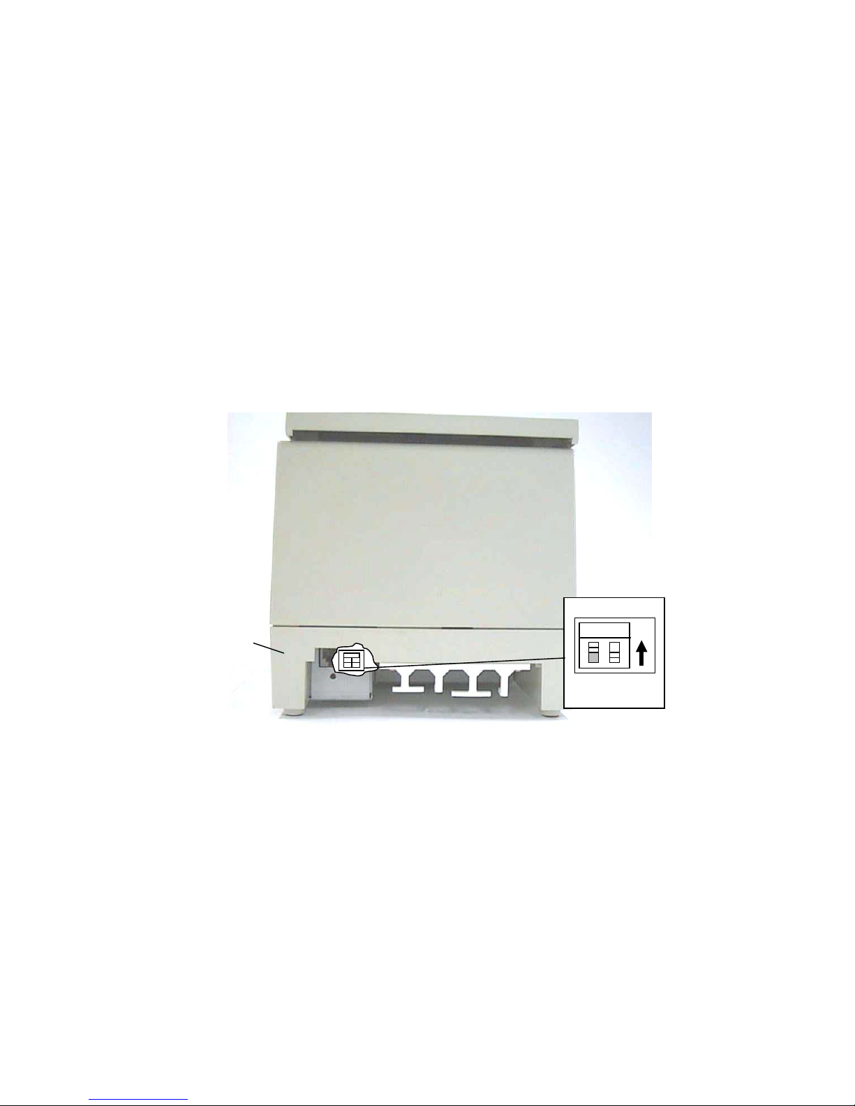
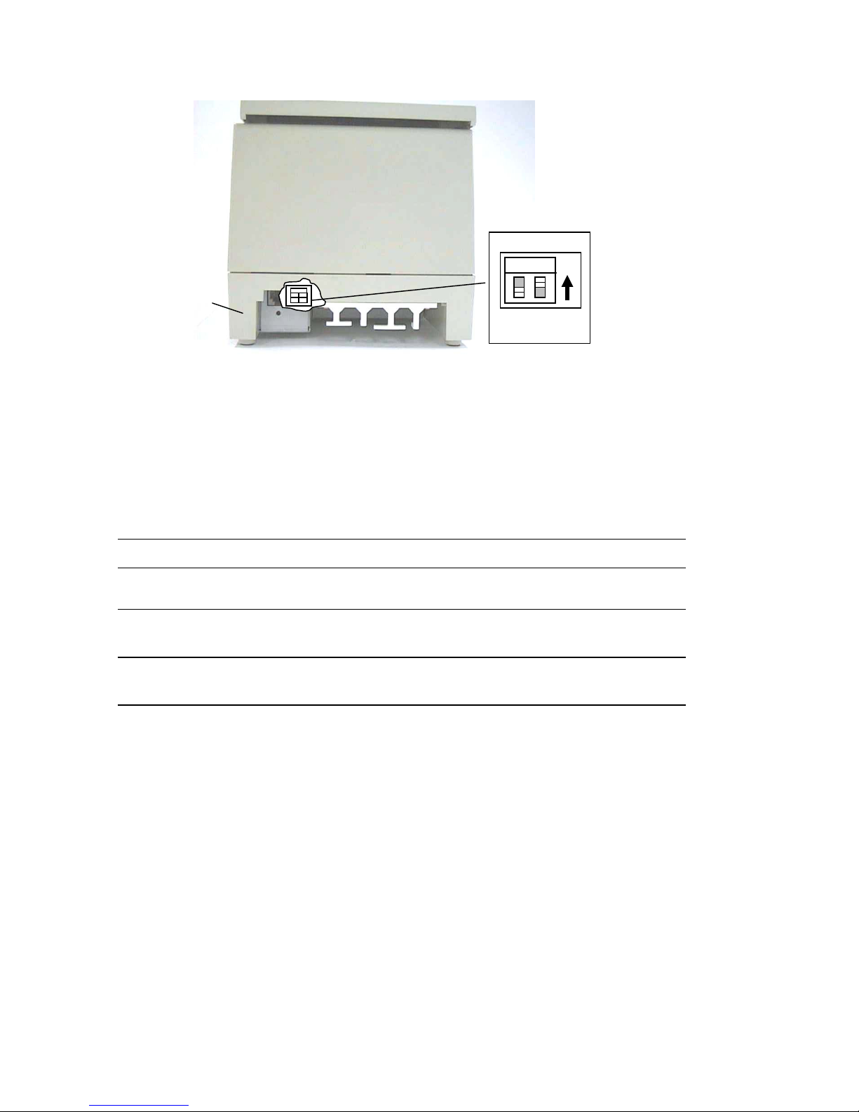
Setting Switches
The DIP switches, located at the back of the printer, are used for two purposes:
• To set variables for several printer functions (see the sections for the various printer
functions in “Level 1 Diagnostics” in “Chapter 4: Diagnostics” for Setting Up the
Printer)
• To perform diagnostic tests (see the sections for the various diagnostic tests in “Level
1 Diagnostics” in “Chapter 4: Diagnostics” for Setting Up the Printer)
Caution: The DIP switches are set at the factory to predetermined settings and should
not be changed unless to change parameters or to reflash the firmware.
Bottom
Cover
Switch 1 is shown in
the OFF positio
Back of Printe
Note: Switch 1 is shown in the Off position for reference.
Use a paper clip or other pointed object to set the switches.
1. Set the switches to the desired settings shown in the table.
2. Reset the printer by disconnecting and reconnecting the power to the
printer.
11 March 2002

7197 Owner’s Manual Chapter 2: Setting Up and Using the Printer
Resetting the Printer
The printer is reset by disconnecting/reconnecting the DC power.
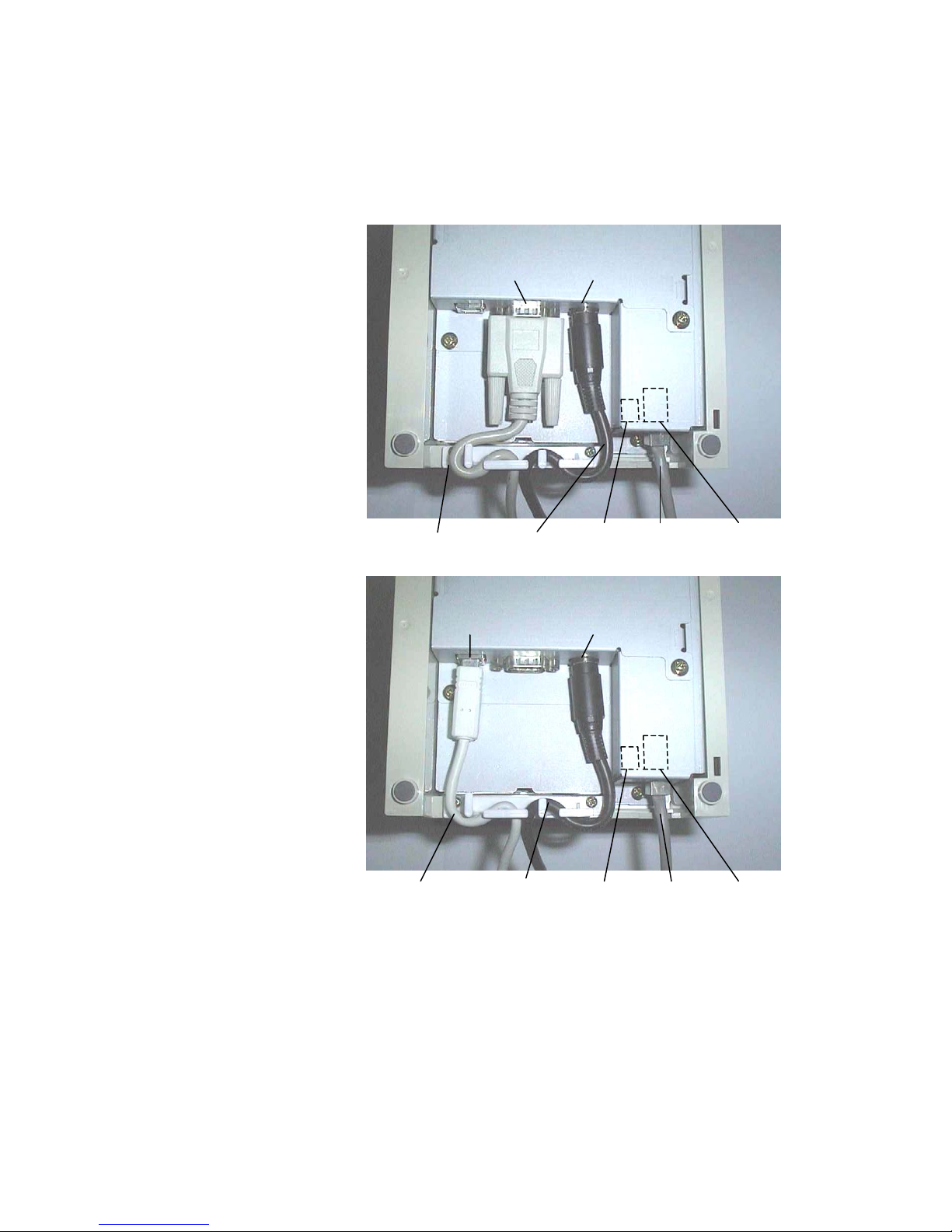
Connecting the Cables
There are three different types of cables that connect to the printer:
• Power supply cable supplying power from the power supply
• Communication cable (RS-232 or USB) connecting the printer to the host computer
• Cash drawer cable connecting the printer to one or two cash drawers
Caution: Disconnect the power before connecting the cables. Always connect the
communication cable and cash drawer cables before connecting power to the power
supply. Always disconnect power to the power supply before disconnecting the
communication and cash drawer cables.
Follow these steps to connect the cables. See the illustration on the next page.
1. Unplug the power supply from its power source.
2. Connect the power and communication cables to their respective connectors under
the printer as shown in the illustration.
For the RS232 Cable, be sure to screw the communication cable to the communication
connector.
3. Route the cables through the cable strain relief on the bottom of the printer, then
through the two slots in the cable access cover as shown in the illustration.
4. Connect the communication cable to the appropriate host computer connector.
5. Connect the cash drawer cable to the printer and cash drawer.
The connectors is a standard phone jack located at the rear of the printer.
6. Plug the power cord into the power supply for remote power supply installation,
then plug the power supply into an outlet.
12 March 2002
7197 Owner’s Manual Chapter 2: Setting Up and Using the Printer
At this point, the printer receives power. If the On Line LED (green) is on, the printer is
on-line. Otherwise, the printer is off-line.
7. For Host powered installation plug the DC cable into the POS terminal.
RS-232 Cable Connection
Communication
Connector
Communication
Cable
USB Cable Connection
USB
Connector
Power
Cable
Power
Connector
DIP Switch
Power
Connector
Cash Drawer
Cable
Cash Drawer
Connector
13 March 2002
USB
Cable
Power
Cable
DIP Switch
Bottom of the Printer
Cash Drawer
Cable
Cash Drawer
Connector

7197 Owner’s Manual Chapter 2: Setting Up and Using the Printer
About the Universal Serial Bus
The Universal Serial Bus (USB) is a peripheral bus for personal computers that was first
released in January 1996. Since that time, virtually all Intel Architecture personal
computers have the hardware to support USB, and a large number of computers exist
that have both the hardware and software support required to interface with USB
peripherals.
Advantages of USB connections
USB has a number of advantages over legacy connection schemes (e.g., serial RS-232).
These advantages include:
• High Speed: up to 12 MB/second for high-speed devices.
• Plug and Play: Devices are automatically recognized and configured at installation.
• Hot plug: Bus supports installation and removal of devices with the power applied.
• Up to 127 devices: One host can support up to 127 devices with the use of hubs.
• “Free ports”: Most PC architecture machines contain two USB ports in the base
hardware.
These advantages have become attractive to the POS industry for a couple of reasons.
Additional POS devices. Some POS systems are required to host more peripherals than
can be supported by two RS-232 ports typical in a platform. With the addition of one (or
two) USB connectors, the platform can now support the additional devices that had
previously required a serial port expander card.
Higher bandwidths. New devices coming into use have bandwidth requirements that
are higher than the bandwidth that can be supported on legacy interfaces. These devices
include image scanners and printers. As the speed and capability of POS printers
increases, the performance of the printer in an application can become limited by the
speed of the communications interface. USB provides ample bandwidth to support
current and future POS printer requirements.
Advantages of the NCR USB Solution
NCR has eliminated any cost associated with porting applications to USB by
implementing a USB solution that simulates standard serial communications in Windows
98 (SR2), Windows 98 USB Hot Patch, ID: Q236934, and NT 4.0 (Service Pack 3 or higher)
and Windows 2000. Application developers need only redirect their software to the
virtual serial ports created by the NCR USB solution to use the printer.
14 March 2002

7197 Owner’s Manual Chapter 2: Setting Up and Using the Printer
Checking for USB Support on the Host Computer
If USB interface communications is required, the host computer must be equipped and
setup properly. If it is not, you need to install a USB interface card. With the required
hardware in place, Windows 98 (SR2), Windows 98 USB Hot Patch, ID: Q236934, NT 4.0
(Service Pack 4.0 or higher) and Windows 2000 (Service Pack 2.0 or higher) natively
support plug-and-play USB with a built-in driver; Windows NT does not, and the NCR
windows NT USB driver needs to be installed.
IMPORTANT: You need to have internet access to download the USB drivers from the
NCR Web site://www.NCR.com.
Host Configuration
Verify that the proper hardware has been installed in the host PC.
Windows 98:
1. Open the Control Panel.
2. Click on System (Windows 98).
3. Click the Device Manager tab.
4. In the Device Manager window, scroll down the list of installed hardware devices
until you find an entry for “Universal serial bus controller.”
If this entry exists, your host computer is set up for USB operation. If this entry does not
appear:
Consult your computer documentation to see if USB must be enabled in the BIOS setup.
•
Windows NT:
To see if your POS terminal is USB-compliant, look at the back.
• If it has a USB connector port, your hardware is all set.
Note: Even though the host may have a USB port, Windows NT does not natively
support plug-and-play USB because it does not have a built-in driver. You will need to
load the NCR Windows NT USB driver (see “Installing the USB Printer Drivers”).
• If the connector port is missing, you need to install a third-party USB card, according
to the manufacturer’s instructions.
Note: For Windows NT units requiring the installation of a card, a Windows 98 USB card
can be used with the NCR Windows NT driver.
Windows 2000:
1. Open the Control Panel.
2. Click on System.
15 March 2002
7197 Owner’s Manual Chapter 2: Setting Up and Using the Printer
3. Click the Device Manager tab.
4. In the Device Manager window, scroll down the list of installed hardware devices
until you find an entry for “Universal serial bus controller.”
If this entry exists, your host computer is set up for USB operation. If this entry does not
appear:
•
Consult your computer documentation to see if USB must be enabled in the BIOS setup.
Configuring the Printer
USB is a plug-and-play environment. As such, neither the printer nor the host requires
user configuration to work. However, since the NCR solution simulates a serial
communication interface, you must configure “handshaking” on the printer for proper
operation. The printer can be configured to use hardware flow control (using
DTR/DSR) or software flow control (using XON/XOFF). All other serial
communication parameters (i.e., baud rate, parity, stop bits, and data bits) are ignored.
To define software or hardware handshaking:
1. Open the Receipt Cover and check whether there is paper in the printer. If there
isn’t, insert the paper roll, as described in the Owner’s Manual.
2. Turn the printer so the back is facing you.
3. Set DIP switch 1 to the On position (up).
Receipt cover
Receipt
16 March 2002
7197 Owner’s Manual Chapter 2: Setting Up and Using the Printer
r
n
Bottom
Cover
Switch 2 is shown in
the OFF positio
Back of Printe
4. Reset the printer. See below for information on resetting the printer.
The printer beeps, prints the current configuration, then waits for you to make a
selection from the Main Menu on the printout.
DIP Switch Settings Information
Switch 1 Settings Switch 2 Settings Printer State
OFF (0) OFF (0) On-line Mode (default)
ON (1) OFF (0) Diagnostic Mode
OFF (0) ON (1) Flash Download Mode
ON (1) ON (1) Vendor Adjustment
Mode
17 March 2002
7197 Owner’s Manual Chapter 2: Setting Up and Using the Printer
*** Diagnostics Form ***
Model number
Serial number
Boot Firmware
Revision
CRC
Flash Firmware
Revision
CRC
Hardware
Flash Memory Size
Flash Logos Size
Flash Fonts Size
Flash User Storage
Communication Interface
Interface Type
Parameters
Baud Rate
Data Bits
Stop Bits
Parity
Flow Control
Reception Errors
Receive Buffer
Diagnostic Mode
Emulation/Software
Printer Emulation
Printer ID Mode
Default LPI
Carriage Return
Asian Mode
To enter Printer Configure Menu:
1) Flip DIP switch #1 on
2) Reset the printer by pressing
and holding Receipt Feed
switch down while
disconnecting and reconnecting
7197-1005-9001
:
01000011
:
V00.16
:
35429
:
V01.35
:
D2C3
:
2Mbytes
:
256Kbytes
:
64Kbytes
:
64Kbytes
:
RS232/USB
:
9600
:
8
:
1
:
None
:
DTR/DSR
:
Print ‘?’
:
4K
:
Off, Normal Mode
:
:
7194 Native Mode
:
7194 Native ID
:
7.52
:
Used as Print Cmd
:
Off
:
*** Printer Config Menu ***
The config menu allows you to set general
printer parameters. Sub-menus are entered and
selections are made using the Paper Feed
Button:
- Short Click : Feed Button is
quickly depressed
then released.
- Long Click : Feed Button is held
down more than 1sec
then released.
CAUTION !!
The settings are predetermined in
factory and should generally not be
changed to avoid changing other
functions.
**************
************* Main Menu *************
*****************************************
Select a sub –menu:
- EXIT 1 Click
- Print Current Configuration 2 Clicks
- Set Communication Interface 3 Clicks
- Set Diagnostics Modes 4 Clicks
- Set Emulation/Software 5 Clicks
- Set Hardware Options 6 Clicks
- Set Default Code Page 7 Clicks
- Set EEPROM To Default 8 Clicks
Enter code, then hold button down
at least 1 second to validate
Important: Ensure that the configuration
settings match your host computer, if not,
enter the Configuration Menu to make
changes.
Follow the instructions on the scrolling menu, pressing the Paper Feed button to make
selections. Indicate Yes with a long click, and No with a short click.
18 March 2002

7197 Owner’s Manual Chapter 2: Setting Up and Using the Printer
• Press and hold the Paper Feed button for at least one second for a long click.
• Press the Paper Feed button quickly for a short click.
5. Select Set Communication Interface from the Main Menu.
The printer scrolls to the first question.
6. Select RS232/USB.
7. Skip through the parameters with short clicks until Set Flow Control Method is
displayed.
8. Follow the instructions to select either XON/OFF or DTR/DSR, then skip the
remaining communications parameters.
9. When you have finished, set DIP switch 1 to Off (down).
10. Reset the printer.
The printer resets with the new selection. You can verify the new setting by pressing the
Paper Feed button to print out a diagnostics form or by holding the Paper Feed button
while closing the Top Cover.
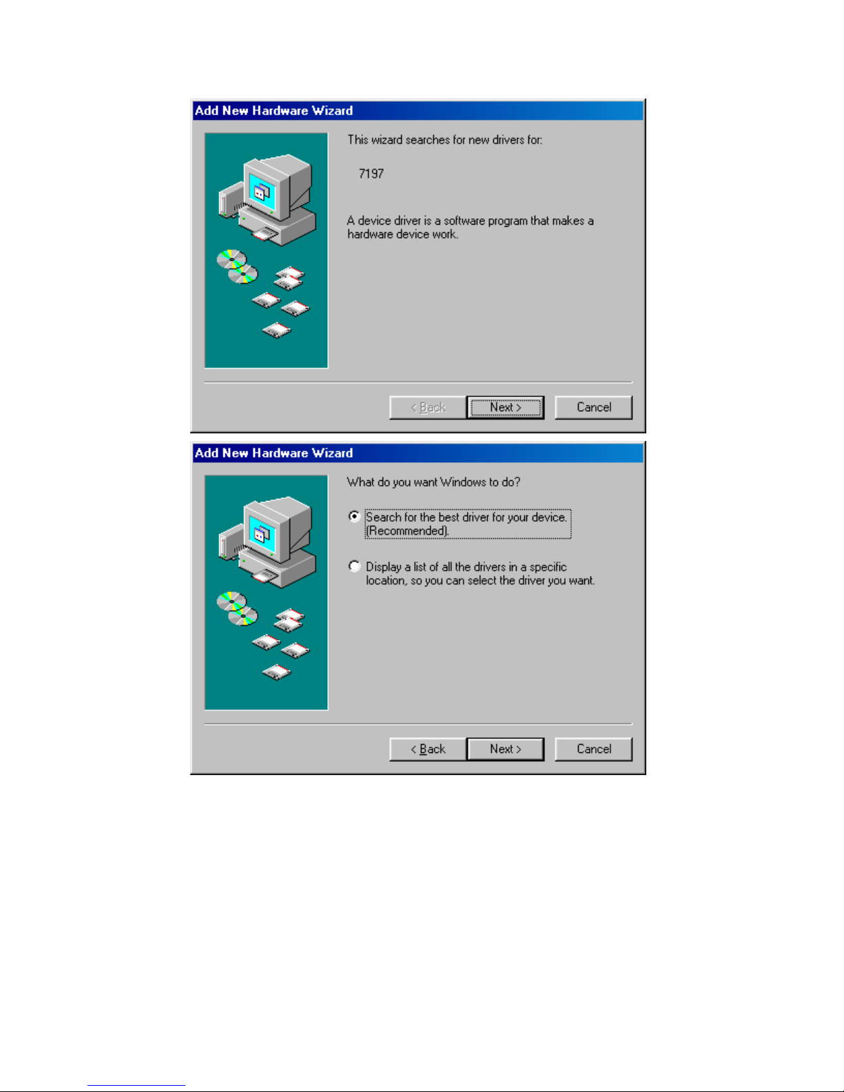
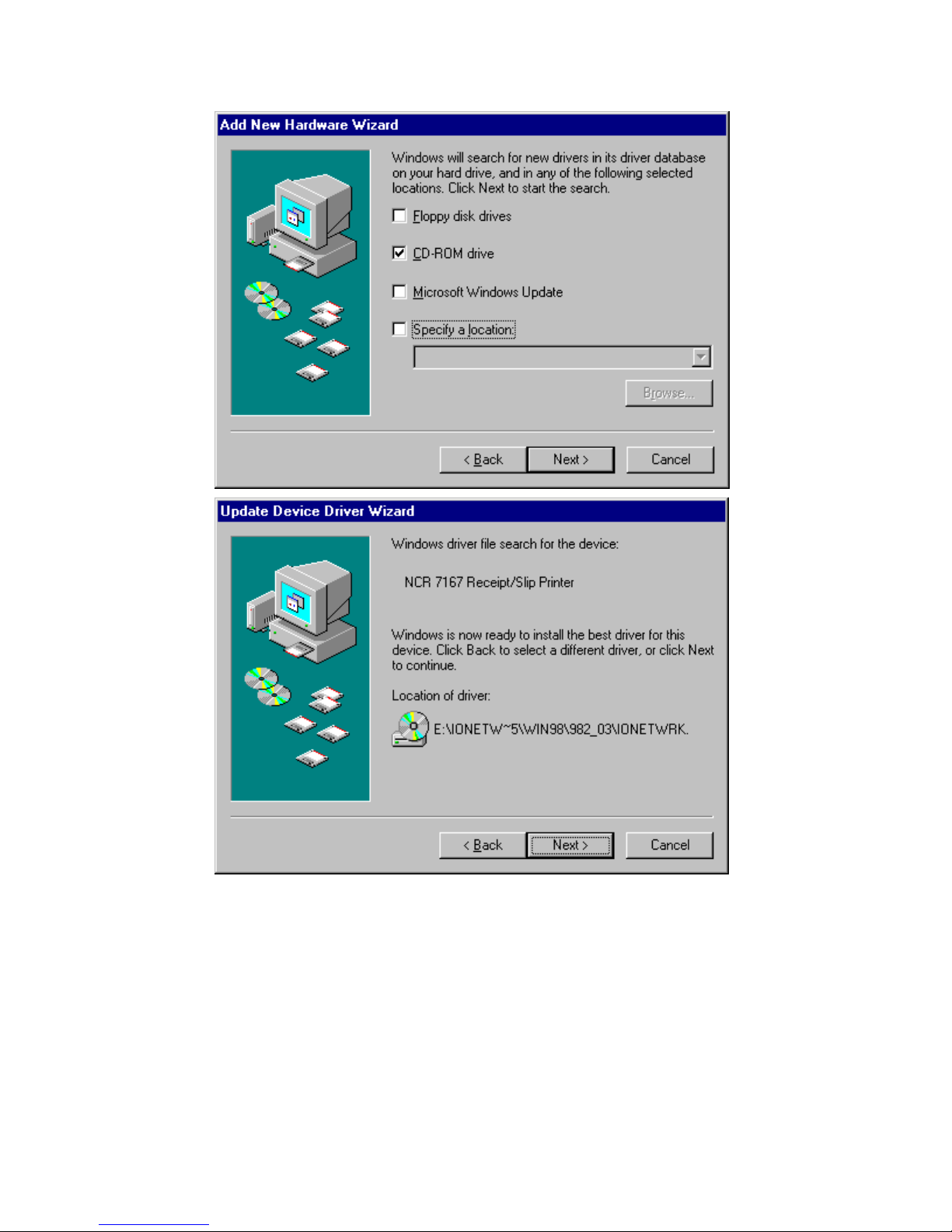
Installing the USB Printer Drivers
Windows NT users need to run Service Pak 3 or higher for a successful installation and
should exit all Windows programs before starting.
1. Verify that the printer is plugged in and the power is on.
2. The installation varies depending on the operating system.
Windows 98
Follow the on-screen instructions. The printer beeps when the USB device is
recognized. Go to the location where you downloaded the drivers and double click the
file.
19 March 2002
7197 Owner’s Manual Chapter 2: Setting Up and Using the Printer
20 March 2002
7197 Owner’s Manual Chapter 2: Setting Up and Using the Printer
Note: Location of the IONetworks files on the CD-ROM may very depending on the version of
the CD that is being used.
21 March 2002
 Loading...