

NCR 7193 Service Manual

NCR 7193 Thermal Receipt
Printer
Service Guide
BD20-1440-A
Issue B
August 1998

The product described in this book is a licensed product of NCR Corporation.
It is the policy of NCR Corporation (NCR) to improve products as new technology, components, software, and firmware
become available. NCR, therefore, reserves the right to change specifications without prior notice.
All features, functions, and operations described herein may not be marketed by NCR in all parts of the world. In some
instances, photographs are of equipment prototypes. Therefore, before using this document, consult with your NCR
representative or NCR office for information that is applicable and current.
To maintain the quality of our publications, we need your comments on the accuracy, clarity, organization, and value of this
book.
Address correspondence to:
Retail Systems Group−Atlanta
NCR Corporation
2651 Satellite Blvd.
Duluth, GA 30136
Copyright © 1997
By NCR Corporation
Dayton, Ohio U.S. A.
All Rights Reserved

7193 Service Guide Contents
Contents
Chapter 1: About the 7193 Printer 1
Models........................................................................................................................................ 1
Communication Interfaces................................................................................................ 1
Features ...................................................................................................................................... 2
Options....................................................................................................................................... 2
Thermal Printhead....................................................................................................................2
Cleaning the Printer.................................................................................................................. 3
Cleaning the Cabinet......................................................................................................... 3
Cleaning the Thermal Printhead...................................................................................... 3
Chapter 2: Installing the Printer 5
What Is in the Box? ................................................................................................................... 5
Removing the Printer ........................................................................................................ 5
Repacking the Printer........................................................................................................ 5
Choosing a Location................................................................................................................. 6
Setting Switches......................................................................................................................... 6
RS-232C Switch Settings.................................................................................................... 8
Parallel Switch Settings..................................................................................................... 9
LCSIO (RS-485) Switch Settings..................................................................................... 10
Connecting Cash Drawer Cables .......................................................................................... 11
Connecting Communication and Power Cables................................................................. 12
RS-232C and LCSIO (RS-485) Models ........................................................................... 12
Parallel Models.................................................................................................................13
Turning On the Printer ........................................................................................................... 14
Testing the Printer................................................................................................................... 15
Models Receiving Power from the Power Supply (Remote)...................................... 15
Models Receiving Power from the Host (Integrated) ................................................. 15
Mounting the Printer on a Wall............................................................................................. 17
Mounting the Power Supply on a Wall................................................................................ 19
Chapter 3: Diagnostics 21
Level 0 Diagnostics................................................................................................................. 21
Level 1 Diagnostics................................................................................................................. 22
Setting Data Error and Data Buffer options ................................................................. 23
Setting Printhead Resistance .......................................................................................... 24
Setting Default Lines per Inch........................................................................................ 25
Setting Partial Cut Distance............................................................................................ 26
Setting the 7150 Response Mode.................................................................................... 27
Ignoring/Using the Carriage Return.............................................................................28
Running the Data Scope Mode....................................................................................... 28
Testing Receipt Printing .................................................................................................. 30
Level 2 Diagnostics................................................................................................................. 31
Level 3 Diagnostics................................................................................................................. 31
August 1998 vii

Contents 7193 Service Guide
Chapter 4: Troubleshooting 33
Operator Panel Lights............................................................................................................. 33
Field Effect Transistors (FETs))............................................................................................. 34
Operating Problems................................................................................................................ 35
Electronic Problems................................................................................................................ 37
Printing Problems ................................................................................................................... 37
Chapter 5: Disassembling and Reassembling the Printer 39
Getting Started......................................................................................................................... 39
Tools................................................................................................................................... 39
Removing the Receipt Cover.......................................................................................... 40
Removing the L Cover.....................................................................................................41
Removing the Print Mechanism and PC Board Assembly................................................ 42
Separating the Print Mechanism and PC Board Assembly ............................................... 44
Disconnecting Cables....................................................................................................... 45
Disassembling the Print Mechanism.................................................................................... 46
Removing the Knife Assembly....................................................................................... 46
Replacing the Knife Assembly....................................................................................... 47
Removing the Printhead................................................................................................. 48
Replacing the Printhead.................................................................................................. 49
Removing the Knife Motor............................................................................................. 49
Replacing the Knife Motor.............................................................................................. 50
Removing the Switches................................................................................................... 50
Replacing the Switches.................................................................................................... 51
Removing the Paper Feed Motor................................................................................... 51
Replacing the Paper Feed Motor.................................................................................... 51
Disassembling the PC Board Assembly............................................................................... 52
Removing the ESD/EMC Shield.................................................................................... 52
Replacing the ESD/EMC Shield.................................................................................... 52
Replacing the Print Mechanism ............................................................................................ 53
Replacing the PC Board Assembly on the Print Mechanism ..................................... 53
Reconnecting the Cables and Harnesses....................................................................... 53
Replacing the Print Mechanism ............................................................................................ 54
Finishing Up ............................................................................................................................ 54
Replacing the L-Cover..................................................................................................... 54
Replacing the Receipt Cover...........................................................................................54
Checking out the Printer................................................................................................. 54
Appendix A: Specifications 55
Features .................................................................................................................................... 55
Reliability ................................................................................................................................. 55
Environmental Conditions..................................................................................................... 55
Power Requirements............................................................................................................... 56
Dimensions and Weight......................................................................................................... 56
Printing Specifications............................................................................................................ 57
Density of Receipt Print Lines............................................................................................... 58
Duty Cycle Restrictions (Printing Solid Blocks).................................................................. 58
August 1998viii

7193 Service Guide Contents
Appendix B: Ordering Paper and Supplies 59
Ordering Thermal Paper........................................................................................................ 59
Ordering Other Supplies........................................................................................................ 60
Order from Other Equipment Manufacturers.............................................................. 60
Order from Axiohm......................................................................................................... 60
Appendix C: Kits 61
Appendix D: Connectors 63
Power Connector..................................................................................................................... 63
RS-232C Connector ................................................................................................................. 63
RS-232C 25-Pin to 9-Pin Cable Diagram ....................................................................... 64
RS-232C 9-Pin to 9-Pin Cable Diagram ......................................................................... 64
Parallel Connector ................................................................................................................... 65
LCSIO (RS-485) Connectors................................................................................................... 65
Powered from Host.......................................................................................................... 65
Powered from Power Supply......................................................................................... 66
Cash Drawer Connectors....................................................................................................... 66
Appendix E: Commands 67
Command List......................................................................................................................... 67
Printer Function Commands.......................................................................................... 68
Print Characteristics Commands................................................................................... 69
Graphics Commands....................................................................................................... 70
Printer Status Commands............................................................................................... 70
Real Time Commands..................................................................................................... 70
Bar Code Commands....................................................................................................... 71
Index 73
August 1998 ix

Contents 7193 Service Guide
August 1998x
7193 Service Guide Chapter 1: About the 7193 Printer
Chapter 1: About the 7193 Printer
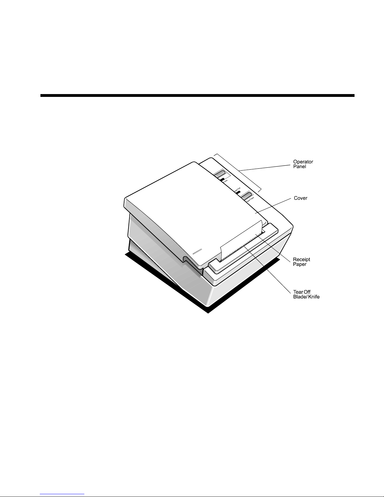
The 7193 thermal receipt printe r is fast, quiet, and very reliable. W ith thermal printing
technology, there is no ribbon cassette to change, and paper loading is extremely simple.
The printer is small enough to fit almost anywhere and is easy to use with the receipt
exiting from the top. There is no journal as it is kept electronically by the host system.
Models
There are several models of the 7193 depending on the communication interface and the
combination of options selected.
Communication Interfaces
• RS-232C
• Parallel
• LCSIO (RS-485)
See “Appendix D: Connec tors” later in this book or the Owner's Guide for more
information.
August 1998 1

Chapter 1: About the 7193 Printer 7193 Service Guide
Features
All models come with the following features:
• Drop-in paper loading which does not require using a spindle or threading the paper
through a paper path
• Host-selectable 44 or 56 columns of print on 80 mm wide “fax grade” thermal paper
• Two resident selectable character sets:
• PC Code Page 437 (US)
• PC Code Page 850 (Multilingual)
• 16K RAM available for download ab le character sets and bit-mapped graphics
• 4K buffer (RS-232C and Parallel)
• History EEROM
• Speaker
• Resident bar codes
• Code 39
• UPC-A
• UPC-E
• JAN8 (EAN)
• JAN13 (EAN)
• Interleaved 2 of 5
• Codabar
• Code 128
Options
The following options are available:
• Remote power supply with wall-mount kit
• Standard with RS-232C and Par allel interface models
• Optional with LCSIO (RS-485) models: these models may be powered through the
• Paper cutter
• Cash drawer drivers: will open a separately purchased cash drawer under software
command (RS-232C and Parallel only)
• Wall-mount kit for hanging the printer on a wall
Thermal Printhead
The 7193 uses a thermal printhead which is extr emely fast and quiet. Because it uses heat
to print directly on paper, there is no cassette or ribbon to change, eliminating soiled
fingers and paper dust.
The printhead is designed for a very long life, but it may be replaced if needed. See
“Troubleshooting” later in this book for information on when to rep lace the printhead. See
“Removing the Printhead” in “Disassembling and Reassembling the Printer” later in this
remote power supply or through the host system
August 19982

7193 Service Guide Chapter 1: About the 7193 Printer
book for instructions on replacing the printhead. See “Cleaning the Printer” later in this
chapter for cleaning instructions for the printhead.
Cleaning the Printer
Cleaning the Cabinet
Clean the cabinet as needed to remove dust and finger marks. Use any household cleaner
made for plastics, but test it first on a small unseen area. If the receipt paper bucket is dirty,
wipe it with a clean, damp cloth. The cabinet materials and finish are durable and are
resistant to the following items:
• Cleaning solutions
• Lubricants
• Fuels
• Cooking oils
• Ultraviolet light
Cleaning the Thermal Printhead
If the printhead appears dirty, clean it with cotton swabs and rubbing alcohol.
Caution: Do not spray the thermal printhead with household cleaner as this may damage
it and the electronics.
If spotty or light printing problems persist after cleaning the thermal printhead, contact
your NCR authorized service representative.
Note: The thermal printhead does not normally require cleaning if the recommended
paper grades are used. If non-recommended paper has been used for an extended period
of time, cleaning the printhead with the alcohol pen will not be of much benefit.
If this is the case, the printhead will need to be changed. See “Removing the Printhead” in
“Disassembling and Reassembling the Printer” later in this book for instructions on
replacing the printhead.
August 1998 3

Chapter 1: About the 7193 Printer 7193 Service Guide
August 19984

7193 Service Guide Chapter 2: Installing the Printer
Chapter 2: Installing the Printer
What Is in the Box?
The following items are packed in the shipping box (printers shipped in bulk may not
include all of these items):
•
Printer enclosed in a plastic bag and foam pack
• Thermal paper roll (inside printer)
• Test printout protecting the printhead (inside printer)
• Power supply with attached cable to printer (only if ordered with the printer)
• Power cord—from power supply to outlet (only if ordered with the printer)
• Wall-mount holder for the power supply with screws and wall anchors (only if
ordered with the power supply)
•
Tie-wrap for cable
• Installation report card (please complete this form and return to NCR)
• 7193 Thermal Receipt Printer: Setup and User’s Guide
These items may be ordered as options from NCR and will be shipped separately:
• Wall-mount kit for the printer
• Communication cable (from host computer to printer)
• Cash drawer with cables
Removing the Printer
1. Remove the printer from the foam pack and open the receipt cover by pulling up on
2. Remove the paper roll and test printout from inside the printer.
3. Save all packing materials for future storing, moving, or shipping the printer.
4. Complete the Installation report card and send it to NCR.
Repacking the Printer
1. Protect the printhead by placing a piece of receipt paper between the receipt cover and
2. Place the printer in the plastic bag and foam pack.
3. Place the packed printer in the box and secure the box with packing tape.
4. If you are sending the printer directly to NCR for repair, call your NCR-authorized
the front left corner.
the printhead.
service representative for instructions on where to send the printer.
Be prepared to answer questions concerning shipping and billing.
August 1998 5
Chapter 2: Installing the Printer 7193 Service Guide
Choosing a Location
The 7193 is compact and requires little counter space. It may even be mounted on a wall if
space is at a premium. See “Mounting the Printer on a Wall” later in this chapter. The
power supply, if used, may also be mounted on a wall or under a table. See “Mounting the
Power Supply on a Wall” later in this chapter. Be sure to plan for the length of the
communication and power cables when choosing a location.
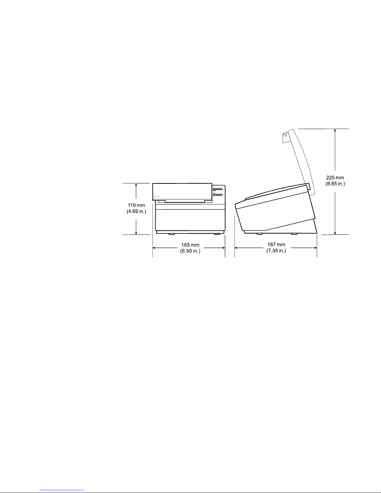
Make sure there is enough room to open the receipt cover and change the paper. The
following illustration shows the actual dimensions of the printer, but leave several inches
around the printer for connecting and accessing the cables.
Setting Switches
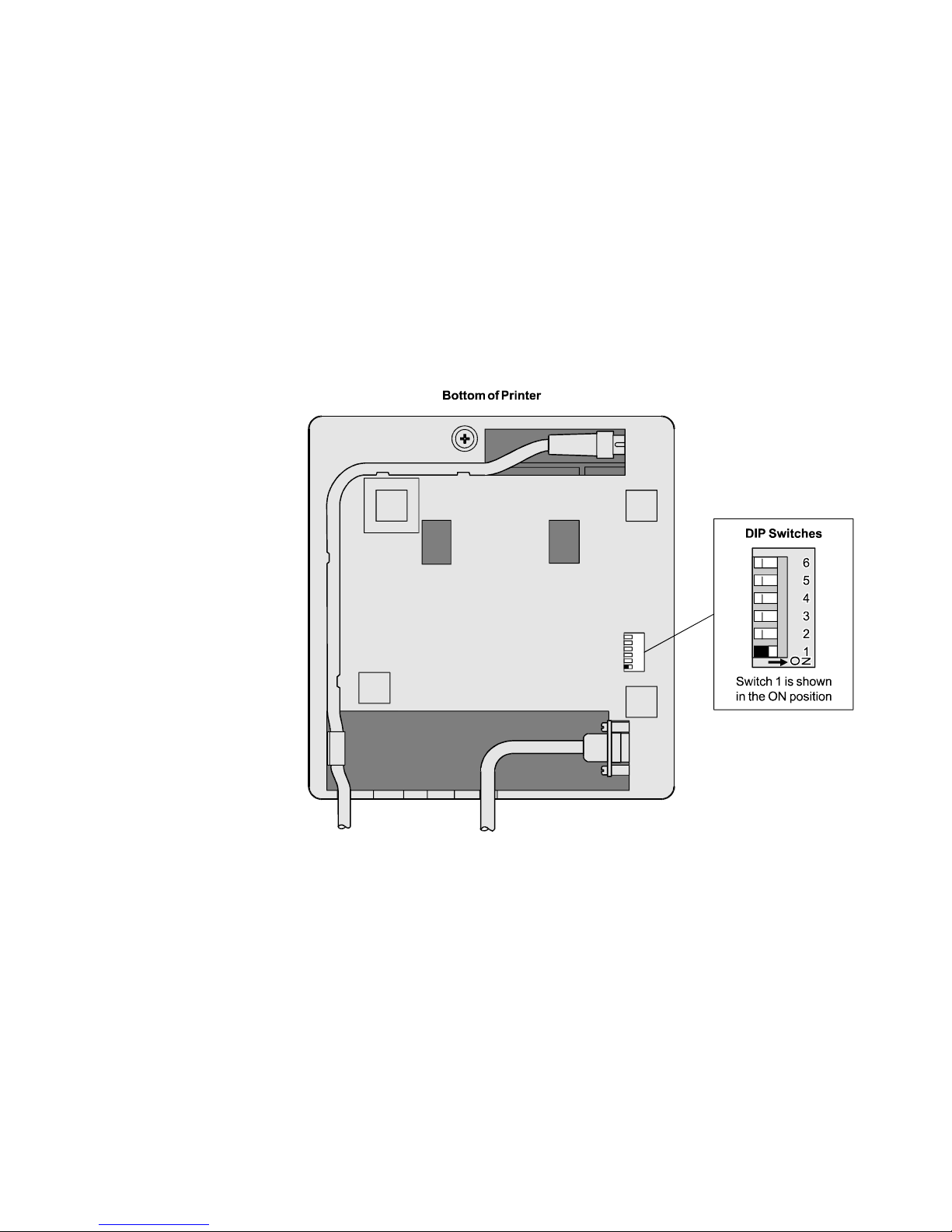
The DIP switches control communication between the printer and host computer and are
located on the bottom of the printer. The switches are used for the following purposes:
• To set variables for several printer functions (see the sections for the various printer
• To perform diagnostic tests (see the sections for the various diagnostic tests in “Level 1
• To set communication parameters for the RS-232C communication interface
• To set the data buffer for the Parallel communication interface (see “Parallel Switch
• To set the address bits for the LCSIO (RS-485) communication interface
Caution: The DIP switches are set at the factory to predetermined settings and should
generally not be changed. If you must change the settings do so carefully to avoid
changing other functions.
Before changing any of the switches, first run the print test to print out the current switch
settings on the receipt. See “Testing the Printer” later in this chapter for instructions on
running the print test and for a sample printout.
functions in “Level 1 Diagnostics” in the “Diagnostics” chapter)
Diagnostics” in the “Diagnostics” chapter)
(see “RS-232C Switch Settings” later in this chapter)
Settings” later in this chapter)
(see “LCSIO—RS-485 Switch Settings” later in this chapter)
August 19986
7193 Service Guide Chapter 2: Installing the Printer
Note: Switch #1 is used to toggle between regular communication with the host computer
and Level 1 Diagnostics (used for the printer functions and level 1 diagnostic tests):
• Switch #1 set to OFF: printer is ready to communicate with the host computer and
receive data (online mode)
• Switch #1 set to ON: printer is in Level 1 Diagnostics (setup mode)
If you want the printer to communicate with the host computer, be sure switch 1 is OFF.
Use a paper clip or other pointed object to set the switch.
For additional information on the setup mode (Level 1 Diagnostics), see the “Diagnostics”
chapter.
Note: Some 7193 models may appear slightly different than what is shown in the
illustration. The procedures are the same for all models unless otherwise noted.
August 1998 7

Chapter 2: Installing the Printer 7193 Service Guide
RS-232C Switch Settings
Use the DIP switches to set the RS-232C parameters and the Data Error and Data Buffer
options as shown. The parameters must match the host computer. See “Level 1
Diagnostics” in the “Diagnostics” chapter for more information.
Caution: The switches can also be used for setting other functions and tests. Be careful
when setting the switches for the RS-232C settings that you do not accidentally change the
settings for the other functions and tests.
DIP Switch Settings for RS-232C Parameters
Switch Settings Description
1OFF
RS-232C Communication: On-line Mode
(Default)
ON
2OFF
ON
3OFF
ON
4* OFF
ON
5, 6 5
OFF
ON
OFF
ON
6
OFF
OFF
ON
ON
Level 1 Diagnostics: Setup Mode
DTR/DSR Protocol (Default)
XON/XOFF Protocol
Parity Disabled (Default)
Parity Enabled
Odd Parity
Even Parity
19,200 Baud
9600 Baud (Default)
4800 Baud
1200 Baud
*Switch 4 is not used if the parity is disabled (switch 3 set to OFF).
Note: The following options are set with the printer in the setup mode. See “Level 1
Diagnostics” in the “Diagnostics” chapter for more information.
DIP Switch Settings for Data Error and Data Buffer Options (Choose one from each option)
Switch 1 Switch 2 Switch 3 Switch 4 Switch 5 Switch 6 Option
On Off On Off Off Off “?” for Data Errors*
On Off On Off Off On Ignore Data Errors
On Off On Off On Of f 4K Byte Data Buffer*
On Off On Off On On One Line Data Buffer
*Default
August 19988

7193 Service Guide Chapter 2: Installing the Printer
Parallel Switch Settings
When switch 1 is set to Off, the printer is on-line and ready to communicate with the host
computer. For systems using non-standard ACK handshaking, this option is on Switch 2.
DO NOT select the ACK handshaking option without fully understanding your system
requirements.
Switch 1 Switch 2 Switch 3 Switch 4 Switch 5 Switch 6 Option
Off On Off Off Off Off ACK Handshaking (On-line)
Off Off Off Off Off Off Standard Busy Handshaking
(On-line)
Caution: The switches can also be used for setting other functions and tests. Be careful
when setting the switches for the Data Buffer settings that you do not accidentally change
the settings for the other functions and tests.
Note: The Data Buffer option is set with the printer in the setup mode. See the table below,
and see “Level 1 Diagnostics” in the “Diagnostics” chapter for more information.
Switch 1 Switch 2 Switch 3 Switch 4 Switch 5 Switch 6 Option
On Off On Off On Off 4K Byte Data Buffer ( Default)
On Off On Off On On One Line Data Buffer
August 1998 9

Chapter 2: Installing the Printer 7193 Service Guide
LCSIO (RS-485) Switch Settings
For printers using the LCSIO (RS-485) interface, the DIP switches are used to set the LCSIO
(RS-485) address bits as shown in the following table.
DIP Switch 1 (Set to Off when setting address bits)
Off = LCSIO (RS-485) Communication, On-line Mode (Default)
On = Level 1 Diagnostics: Setup Mode
DIP Switch 2 is always Off
Address w/Parity Address
w/o Parity Switch 3 Switch 4 Switch 5 Switch 6
3C BC Off Off Off Off
3D 3D Off Off Off On
3E 3E Off Off On Off
3F BF Off Off On On
40 40 Off On Off Off
41 C1 Off On Off On
42 C2 OffOnOnOff
43 43 Off On On On
44 C4 On Off Off Off
45 45 On Off Off On
46 46 On Off On Off
47 C7 On Off On On
48 C8 On On Off Off
49 49 On On Off On
4A 4A On On On Off
4B CB On On On On
August 199810
7193 Service Guide Chapter 2: Installing the Printer
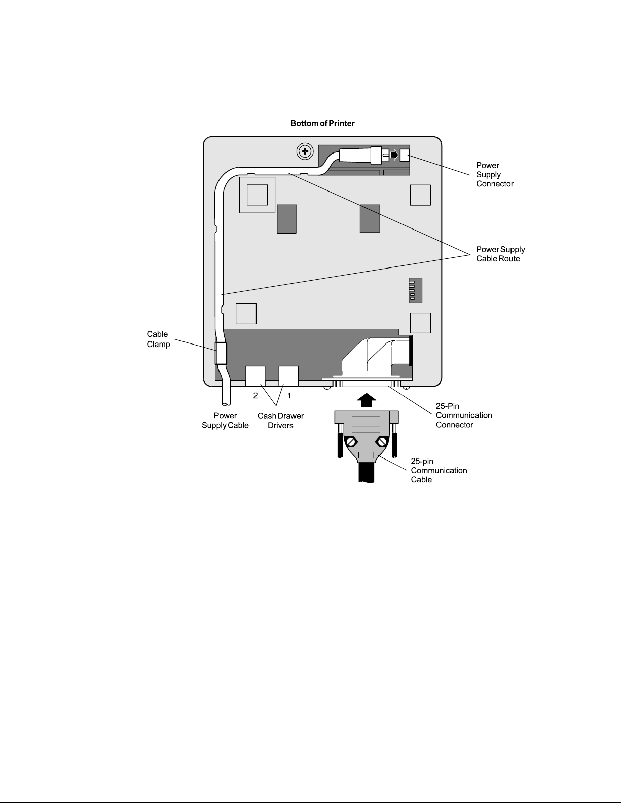
Connecting Cash Drawer Cables
The cash drawer option is available with RS-232C interface and Parallel interface models.
This option allows up to two cash drawers to be connected to the printer in a system with a
PC that has no connectors for the cash drawer cables. The cash drawer cables usually come
with the cash drawer.
The cash drawers are operated by software command from the host computer through the
printer. For additional information on the printer commands used by the host computer to
activate the cash drawers, see “Appendix E: Commands.”
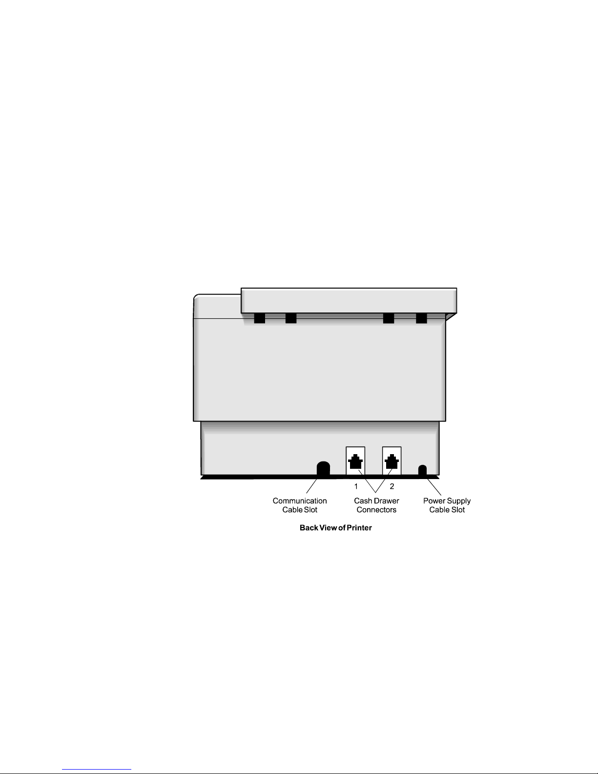
1. Plug the cash drawer cables into the connector s on the printer.
The connectors are standard phone c onnectors.
2. If only one cash drawer is used, plug the cable into the connector labeled 1.
Note: Some 7193 models may appear slightly different than what is shown in the
illustration. The procedures are the same for all models unless otherwise noted.
August 1998 11
Chapter 2: Installing the Printer 7193 Service Guide
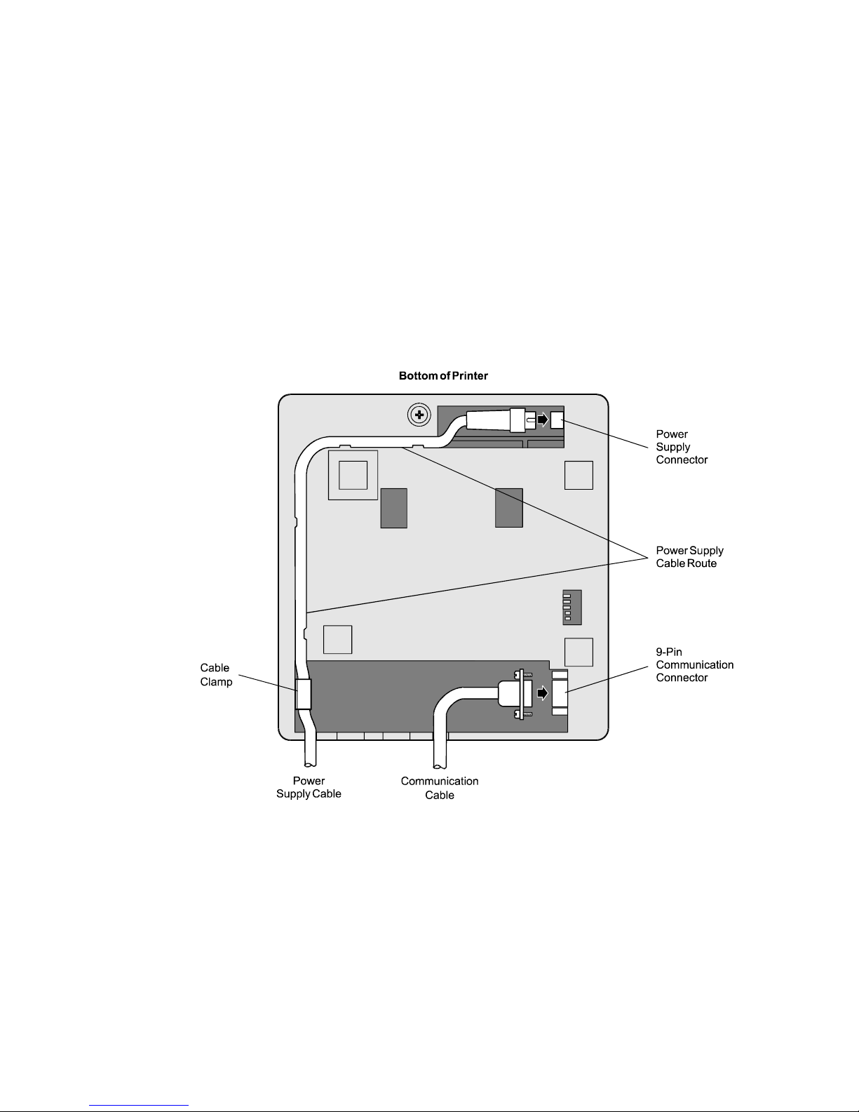
Connecting Communication and Power Cables
Models receiving power from the host computer (integrated), use one cable for
communication and power. Models receiving power from a power supply (remote), use
one cable for communication and a separate cable for power.
Caution: Be sure that all power is disconnected befor e connecting the cables.
1. Turn off the host computer or unplug the power supply if it is plugged in.
2. If the power supply is used, plug the power supply cable into the printer first, then
plug the power cord into the power supply, then into an outlet.
3. Connect the communication cable to the printer, then to the host computer.
RS-232C and LCSIO (RS-485) Models
August 199812
7193 Service Guide Chapter 2: Installing the Printer
Parallel Models
August 1998 13
Chapter 2: Installing the Printer 7193 Service Guide
Turning On the Printer
Note: On models receiving power from a power supply, the printer receives power when
the power supply is on even if the printer is off-line. To remove power from the printer,
press the On Line button to take the printer off-line (On Line is off), then unplug the power
supply power cord from the outlet.
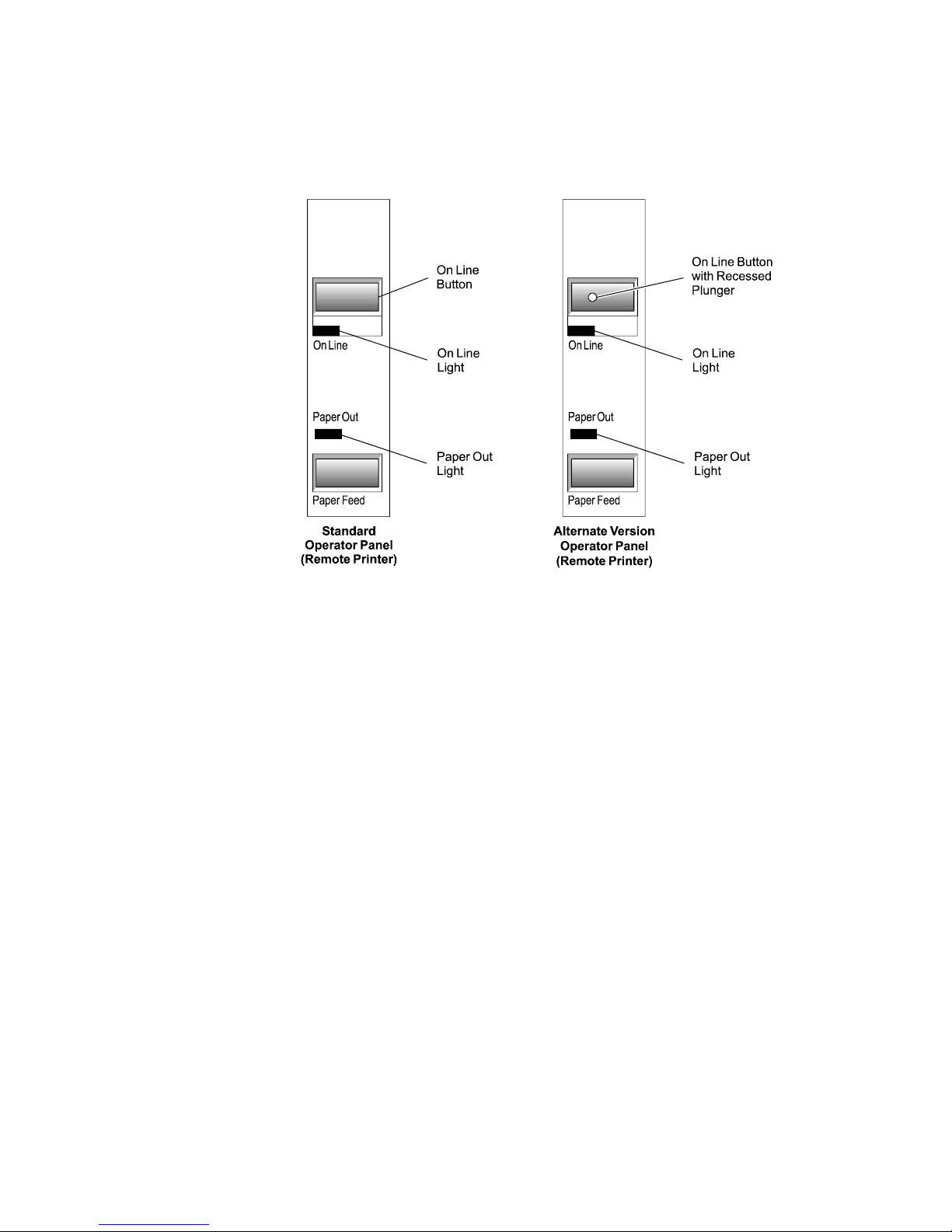
1. Press the On Line button on the operator panel to put the printer on-line.
The printer goes through a self-test routine to ensure everything is working, then
“beeps.” The On Line light (green) comes on indicating the printer is on-line. If the On
Line light does not come on, or either the On Line light or Paper Out light flashes, see
“Troubleshooting” later in this book.
2. Press the On Line button again to take the printer off-line.
Note: On models receiving power from the host computer (integrated), the printer
receives power when the communication cable has been connected and the host turned on.
The printer then goes through a self-test routine to ensure everything is working, then
“beeps.” There is no On Line button or light.
When the printer has completed its “startup” cycle it is ready to receive data. If the Paper
Out light flashes, see “Troubleshooting” later in this book.
August 199814

7193 Service Guide Chapter 2: Installing the Printer
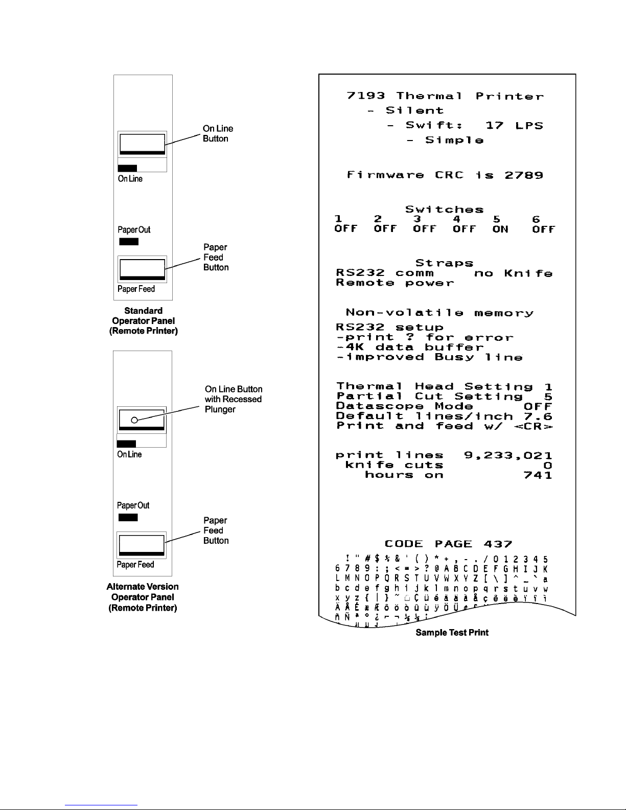
Testing the Printer
Run this test to check the printer. The test prints the settings for several functions, prints all
variations of the character sets, and partially cuts the paper between each variation. See the
“Diagnostics” chapter for a description of the functions.
A sample printout (RS-232C) is shown later in this section. The printouts for other model s
are similar. The test ends with a partial cut, then begins again. Several feet of paper can be
used to print one pass of the test.
Running the test is slightly different for printers receiving power from the host computer
and printers receiving power from a power supply.
Additional diagnostic tests may be performed. For more information, see “Diagnostics”
later in this book.
Models Receiving Power from the Power Supply (Remote)
1. Press the On Line button on the operator panel to take the printer off-line.
The On Line light turns off indicating the printer is off-line.
2. Press and hold the Paper Feed button while pressing the On Line button.
3. Let go of the Paper Feed button once the printing begins.
The printer begins printing the data and character sets. This can be given to a service
representative if it appears there is a problem.
4. To stop the test, press the On Line button.
The On Line light turns off indicating the printer is off-line.
5. To return to the on-line mode, press the On Line button again.
The printer is ready to receive and print data from the host computer.
Models Receiving Power from the Host (Integrated)
1. Open the receipt cover by pulling up on the front left corner.
The Paper Out light (red) comes on indicating that the receipt cover is open and that
the printer cannot receive or print data (not that the paper is out).
2. Press and hold down the Paper Feed button while closing the receipt cover.
3. Let go of the Paper Feed button once the printing begins.
The printer begins printing the data and character sets. This can be given to a service
representative if it appears there is a problem.
4. To stop the test, press the Paper Feed button.
The printer returns to the on-line mode and is ready to receive and print data from the
host computer.
August 1998 15
Chapter 2: Installing the Printer 7193 Service Guide
August 199816

7193 Service Guide Chapter 2: Installing the Printer
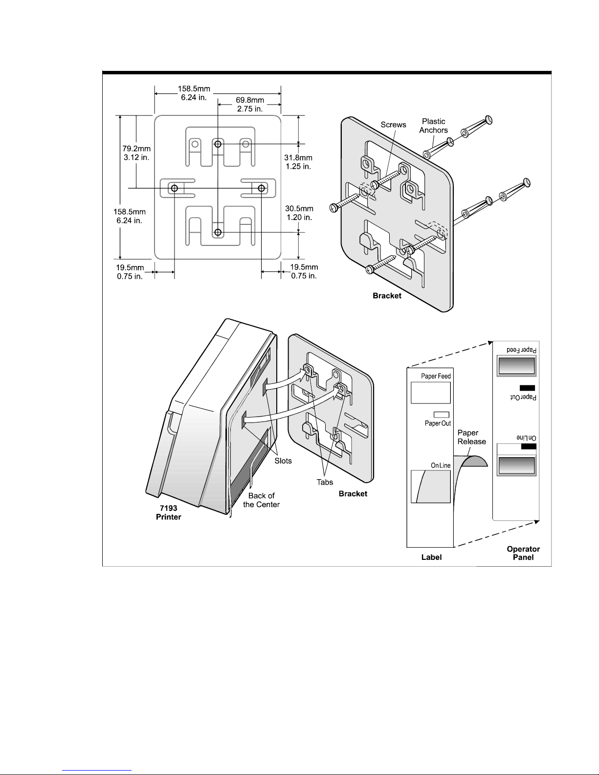
Mounting the Printer on a Wall
Use the wall-mount kit to mount the printer vertically on a wall. See “Appendix B:
Ordering Paper and Supplies” for information on ordering the printer wall-mount kit.
The kit contains a mounting bracket, screws with plastic anchors, and a label. Once the
printer is mounted on the wall, the operator panel will be upside down. The label corrects
this so the panel can be easily read.
Select a wall that is accessible, but away from main traffic to keep the printer from being
bumped or knocked off. Be sure there are no hidden wires or other obstructions in the wall
where you mount the printer. Keep in mind the length of the cables when mounting the
printer on the wall.
Be sure that the rubber pads have been attached to the bottom of the printer. The rubber
pads help the printer to fit snugly against the mounting bracket.
You will need a 1/4 inch drill bit and either a Phillips or standard screwdriver (screws are
combination Phillips and pan-slotted).
1. Using the bracket as a template, mark and drill a hole for each plastic anchor 1.25
inches deep.
2. Insert the anchors into the holes so they are flush with the wall surface and screw the
bracket against the wall, tightening the screws so that the plastic anchors expand and
hold firmly in the wall.
Do not overtighten the screws.
Note: Because the power cable and communication cable connect to the bottom of the
printer, they must be connected before the printer can be attached to the bracket. If you
haven't connected the cables to the printer, do so now. See “Connecting Communication
and Power Cables” earlier in this chapter.
3. Line up the tabs of the bracket with the slots on the back of the printer and attach the
printer to the bracket.
4. Place the label on the cover.
August 1998 17
Chapter 2: Installing the Printer 7193 Service Guide
August 199818

7193 Service Guide Chapter 2: Installing the Printer
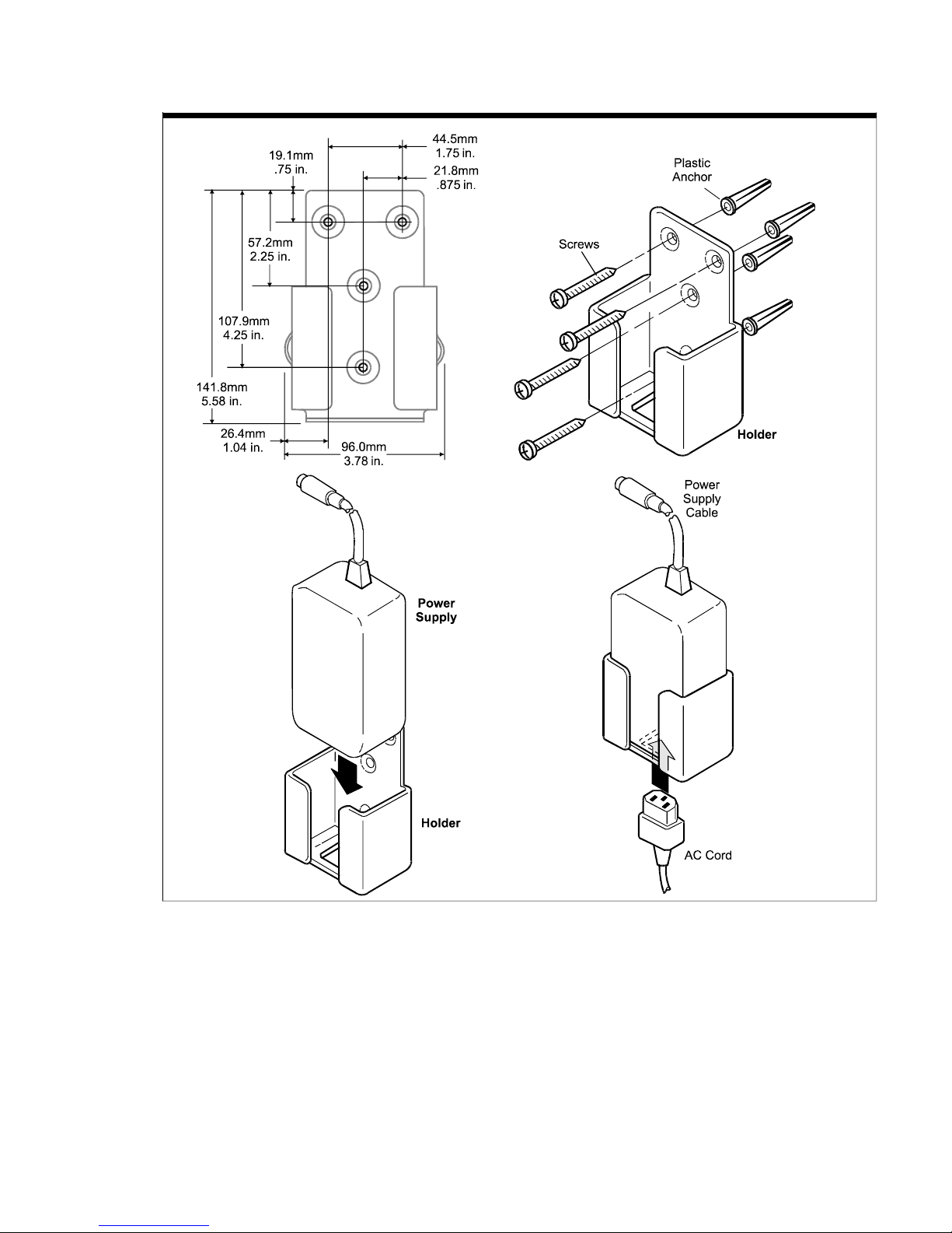
Mounting the Power Supply on a Wall
The power supply comes with a wall-mount kit to mount the power supply on the wall or
under a table. See “Appendix B: Ordering Paper and Supplies” for information on ordering
the power supply and wall-mount kit.
The kit contains a holder and screws with plastic anchors. Be sure there are no hidden
wires or other obstructions in the wall where you mount the power supply.
You will need a 1/4 inch drill bit and either a Phillips or standard screwdriver (screws are
combination Phillips and pan-slotted).
1. Using the bracket as a template, mark and drill a hole for each plastic anchor 1.25
inches deep.
2. Insert the anchors into the holes so they are flush with the wall surface and screw the
holder against the wall, tightening the screws so that the plastic anchors expand and
hold firmly in the wall.
Do not overtighten the screws.
Note: You must unplug the power cord in order to place the power supply in the holder.
First, take the printer off-line by pressing the On Line button on the operator panel (the On
Line light goes off indicating the printer is off-line), unplug the power cord from the outlet,
then unplug the power cord from the power supply.
3. Place the power supply in the holder.
4. Plug the power cord into the power supply.
5. Plug the power cord into an outlet.
Note: You can use the tie-wrap to wrap the power supply cable to keep it out of the way.
August 1998 19
Chapter 2: Installing the Printer 7193 Service Guide
August 199820
 Loading...