

Page 1
User Guide
NCR RealPOS 64-Key (6932) Keyboard
Release 1.0
BCC-0000-5224
Issue A
Page 2

The product described in this document is a licensed product of NCR Corporation.
NCR is a registered trademark of NCR Corporation. NCR RealPOS is a trademark of NCR Corporation in
the United States and/or other countries. Other product names mentioned in this publication may be
trademarks or registered trademarks of their respective companies and are hereby acknowledged.
Where creation of derivative works, modifications or copies of this NCR copyrighted documentation is
permitted under the terms and conditions of an agreement you have with NCR, NCR's copyright notice
must be included.
It is the policy of NCR Corporation (NCR) to improve products as new technology, components,
software, and firmware become available. NCR, therefore, reserves the right to change specifications
without prior notice.
All features, functions, and operations described herein may not be marketed by NCR in all parts of the
world. In some instances, photographs are of equipment prototypes. Therefore, before using this
document, consult with your NCR representative or NCR office for information that is applicable and
current.
To maintain the quality of our publications, we need your comments on the accuracy, clarity,
organization, and value of this book. Please use the link below to send your comments.
Email: FD230036@ncr.com
Copyright © 2018
By NCR Corporation
Duluth, GA U.S.A.
All Rights Reserved
Page 3

Preface
Audience
This book is written for hardware installer/service personnel, system integrators, and
field engineers.
Notice: This document is NCR proprietary information and is not to be disclosed or
reproduced without consent.
Radio Frequency Interference Statements
Federal Communications Commission (FCC)
This equipment has been tested and found to comply with the limits for a Class A digital
device, pursuant to Part 15 of FCC Rules. These limits are designed to provide
reasonable protection against harmful interference when the equipment is operated in a
commercial environment. This equipment generates, uses, and can radiate radio
frequency energy and, if not installed and used in accordance with the instruction
manual, may cause harmful interference to radio communications. Operation of this
equipment in a residential area is likely to cause interference in which case the user will
be required to correct the interference at his own expense.
i
NCR is not responsible for any radio or television interference caused by unauthorized
modification of this equipment or the substitution or attachment of connecting cables
and equipment other than those specified by NCR. The correction of interference
caused by such unauthorized modification, substitution or attachment will be the
responsibility of the user. The user is cautioned that changes or modifications not
expressly approved by NCR may void the user’s authority to operate the equipment.
Canadian Department of Communications
This Class A digital apparatus complies with Canadian ICES-003.
This digital apparatus does not exceed the Class A limits for radio noise emissions from
digital apparatus set out in the Radio Interference Regulations of the Canadian
Department of Communications.
Cet appareil numérique de la classe A est conforme à la norme NMB-003 du Canada.
Le présent appareil numérique n'émet pas de bruits radioélectriques dépassant les
limites applicables aux appareils numériques de la classe A prescrites dans le règlement
sur le brouillage radioélectriques édicté par le ministrère des Communications du
Canada.
Page 4
ii
Voluntary Control Council For Interference (VCCI)
International Radio Frequency Interference Statement
Warning: This is a Class A product. In a domestic environment this product may
cause radio interference in which case the user may be required to take adequate
measures.
Page 5

Out of Box Failure (OBF)
If you experience an out of box failure (OBF) during installation or staging related to a
missing, wrong or defective unit or item, simply provide NCR with a detailed
description of the issue and the item will be replaced free of charge. For assistance with
this process send an email to CustomerSat.Retail@ncr.com with the following details:
• NCR Sales Order # (Sales Order # are located on the box)
• Date of Product Installation
• Product Model #
• Unit Serial #
• NCR part # of defective/missing/wrong component
• Description of Failure (please be specific. For example: “display will not power on”)
• Customer/Requestor’s contact name, phone number and/or e-mail address
• Address to ship replacement part(s)
iii
Warranty
Transport the product in its original packaging to prevent impact damages.
If you do not have access to a computer, you may leave a voice message at: 1-800-5288658 (USA), or (International) +1-770-623-7400. When leaving a message, please provide a
phone number and/or an email address so NCR can contact you if additional details are
needed.
Note: Used equipment that experiences a failure does not qualify as an OBF and should
go through the NCR warranty process.
Warranty terms vary by region and country.
All parts of this product that are subject to normal wear and tear are not included in the
warranty. In general, damages due to the following are not covered by the warranty.
• Improper or insufficient maintenance
• Improper use or unauthorized modifications of the product.
For detailed warranty arrangements please consult your contract documents.
Page 6

iv
Returning Defective Hardware for Service
Use the following procedure to report/return defective hardware.
Call the NCR Customer Care Center at 1-800-262-7782 and have the following information
available when you place the call.
• Class/Model number of the defective equipment
• Serial Number of the defective equipment
• Equipment location in the store
• Description of the problem, including any system error codes, error condition, or
guidance to the area of failure.
The NCR Agent will provide you with a work order number, which serves as your
Return Material Authorization (RMA). Please provide the RMA on the outside of the
shipping box.
Note: A work order must be opened for each device that is shipped for repair.
Page 7

Table of Contents
Chapter 1: Product Overview
Introduction 1
Model Numbers 2
Features 2
Extra Ports 2
Keylock 3
Speaker 4
System Status Indicators 4
v
Magnetic Stripe Reader 5
Chapter 2: Hardware Installation
Environmental Conditions 7
Physical Environment 7
Operating Range 7
Storage Range 7
Transit Range 7
Electrical Environment 8
Dimensions 8
Weight 8
Cable Connection 9
Powering up the Workstation 10
Key Tips and Lens Accessories 11
Key Check Sheet 12
Key Lenses 13
Installing the Key Lens 13
Removing the Key Lens 13
Key Tip 14
Installing a Key Tip 14
Page 8

vi
Removing a Key Tip 14
Chapter 3: Configuration
System Requirements 17
Operating System 17
PS/2 Keyboard and MSR Driver Setup 17
Linux Environment 17
Configuration Access 18
Utility Applications 18
Downloading the Utility Applications 19
NCR Matrix Maker Utility 20
Installing the NCR Matrix Maker Utility 20
Menu Options 22
File 22
Keyboard 22
Diagnostic 26
Using the Matrix Maker Utility 27
Assign Code(s) to a Key using Key Code 29
Updating Keyboard Configuration Using a DAT file 31
Windows Command Line Configuration Utility 32
Windows GUIFirmware Update Utility 33
Windows Command Line Firmware Update Utility 34
Linux Command Line Flash and Configuration Update Utility 35
Keyboard Physical Layout 36
Default Configuration 36
Optional Configuration 36
Key Position Number 37
Unique POS Capabilities 38
32 Programmable POS Keys 38
Numeric keypad layout 39
Double High/Wide Keys 40
Double Key Error Detection 41
Page 9

Num Lock operation 41
Chapter 4: Maintenance and Troubleshooting
Safety Reminders 43
Troubleshooting the Keyboard 44
Keyboard is not working 44
Some keys on the keyboard are not working 44
Numeric keypad is returning wrong keys 45
Speaker is not working 45
MSR is not working 45
Scanner is not working 46
Keylock is not working 46
Cleaning the Keyboard 47
vii
Cleaning the MSR 48
MSR Cleaning and Treatment Cards 48
MSR Treatment Card 48
Cleaning and Treatment Frequency 49
New MSR 49
Existing MSR 49
Page 10

viii
Revision Record
Issue Date Remarks
A
Jan 2018 First Issue
Page 11
Chapter 1: Product Overview
Introduction
The NCR 6932-2XXX 64–Key Keyboard is designed for Point–of–Service (POS)
applications. This keyboard connects to either a PS/2 or a USB port of a computer. It
includes 56 assignable function keys, which are programmable.
The fifty–five keys are blank from the factory and must be programmed using the
Matrix Maker Utility. To download the utility, follow these steps:
1. Go to the NCR Web Site: http://www.ncr.com.
2.
Select the Support tab.
3.
Select Drivers and Patches → Retail Support Files → NCR RealPOS and
SelfServ Peripherals → Keyboards → 6932‐2XXX.
Page 12

1-2 Product Overview
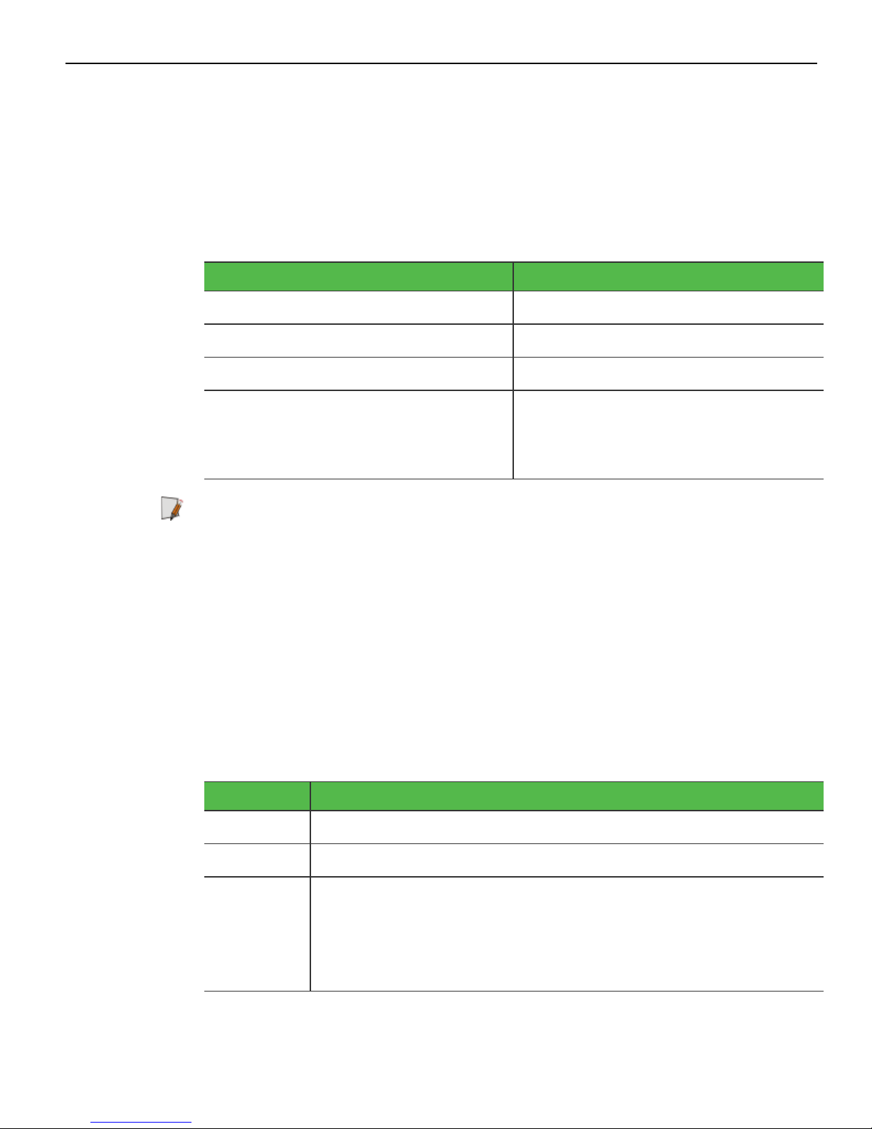
Model Numbers
Product ID Description
Features
6932-22029090
6932-2302-
NCR RealPOS 64-Key POS Keyboard, Keylock, No MSR
(Black)
NCR RealPOS 64-Key POS Keyboard, Keylock, MSR (Black)
9090
6932-22019090
6932-2301-
NCR RealPOS 64-Key POS Keyboard, Keylock, No MSR
(Beige)
NCR RealPOS 64-Key POS Keyboard, Keylock, MSR (Beige)
9090
This section provides information on available features for NCR 6932 64–Key keyboard.
Standard features
• POS matrix layout
• Numeric keypad
• 56 POS function keys
Extra Ports
• LED status indicator
• RS-232 scanner port
Optional features
• 4-position key lock
• 3-track ISO MSR
• PS/2 or USB cable
An extra serial port underneath the keyboard allows customers to connect any
peripheral device such as a scanner or a cash drawer.
When the keylock is in “L” position, the MSR and serial port can be disabled or enabled
by keylock configuration option under software control.
Note: When the keyboard disables the serial port, the keyboard cuts OFF the power
line for the serial device.
Page 13

Product Overview 1-3
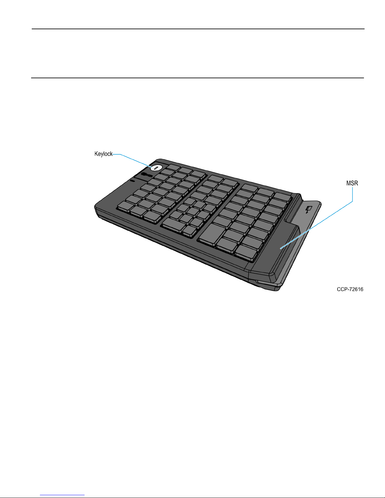
Keylock
The keyboard may include 4–position Keylock. The Keylock switch can be rotated
between specific positions by using 3 keys. These keys provide differential access to
keyboard functions.
The following table explains the keyboard positions.
Abbreviation Position Description
Ex Exception Allows customers or service representatives to
perform low–level programming such diagnostics,
configuration, and loading of the POSterminal
L Locked Locks keyboard input to prohibit use of normal
functions. It can also be programmed to lock or
not lock the MSR, and external USB port. The
default setting is to lock all of those devices.
R Register Allows normal retail mode functions
S Supervisor Allows supervisors to provide the highest level of
POS terminal control such as refunds and running
totals
The following table explains the keys used for the keylock.
KeyLabel Description
Ex Can be inserted and removed only in the “Locked” position and
allows the keylock to be moved only to the “Exception” position.
R Can be inserted and removed from the “Locked” or “Register”
positions and allows the keylock to be moved between these
positions. This key is often used by operators to lock the
keyboard when leaving the station.
S Can be inserted and removed only in the “Locked” and “Register”
positions. This key allows access to the “Supervisor” position but
not to the “Exception” position. This key is typically used by store
supervisors to perform supervisory functions.
Page 14
1-4 Product Overview
Speaker
The programmable speaker provides audible key clicks and error tones for feedback in
both integrated and modular configurations. Keyboards are often located remotely from
the POS terminal. Thus, an integrated keyboard speaker is important for maximum
productivity.
The following table shows the speaker characteristics.
Characteristic Standard
Resonant Frequency 600±20% Hz
Frequency Range 600 to 20,000 Hz
Power Rating 0.5 W
Sound Pressure Level
(at the power level of 0.5 W and the
distance of 0.5 meter)
Note: The user programmable speaker tone function on the USB keyboards is not
supported when the keyboard is connected to a standard PC. The standard PC keyboard
voltage tolerance is not sufficient to handle the extra power requirements of the
programmable speaker tone. Only the default key click and error tones are supported
on a PC.
System Status Indicators
This feature provides the present state of the keyboard. The indicator is a dual color
Red/Green LED. A signal from the keyboard microcontroller selects the status of the
LED.
The following table explains the LEDcolors and their corresponding status indication.
LED Color Description
85±2 dBA
(at 0.8kHz, 1.0kHz, 1.2kHz, and
1.5kHz)
Green The system is generally working properly
Off The system is Off.
Alternately
Flashing
Green and
Red
The keyboard is in the special PCSETUP mode.
Note: In PCSETUP mode, the keyboard is used to run PC
setup routines such as PCBIOS and other configuration or
diagnostics software.
Page 15

Product Overview 1-5
Magnetic Stripe Reader
The Magnetic Stripe Reader (MSR) is an optional feature that provides support for
reading magnetically coded data cards. The NCR 6932 keyboards support a 3–track ISO
MSR.
Page 16

1-6
Page 17
Chapter 2: Hardware Installation
Environmental Conditions
This section lists the physical and electrical environments required for the NCR 69322XXX 64–Key Keyboard.
Warning: Condensation may occur when keyboard is transferred from cold areas to
warm areas during shipment. If condensation has occurred, ensure that the
keyboard has undergone a drying process before its use.
Physical Environment
Operating Range
Condition Range
Temperature 0ºC to +45ºC
Relative Humidity 10% to 90%
Dew Point 26ºC
Storage Range
Condition Range
Temperature -10ºC to +50ºC
Relative Humidity 10% to 90%
Dew Point N/A
Transit Range
Condition Range
Temperature -40ºC to +60ºC
Relative Humidity 5% to 95%
Dew Point N/A
Page 18
2-8 Hardware Installation
Electrical Environment
The electrical environment required for the keyboard module is listed as follows:
PS/2 USB
Power Supply +5V/DC±10% +5V/DC±5%
Current Input <500mA <500mA
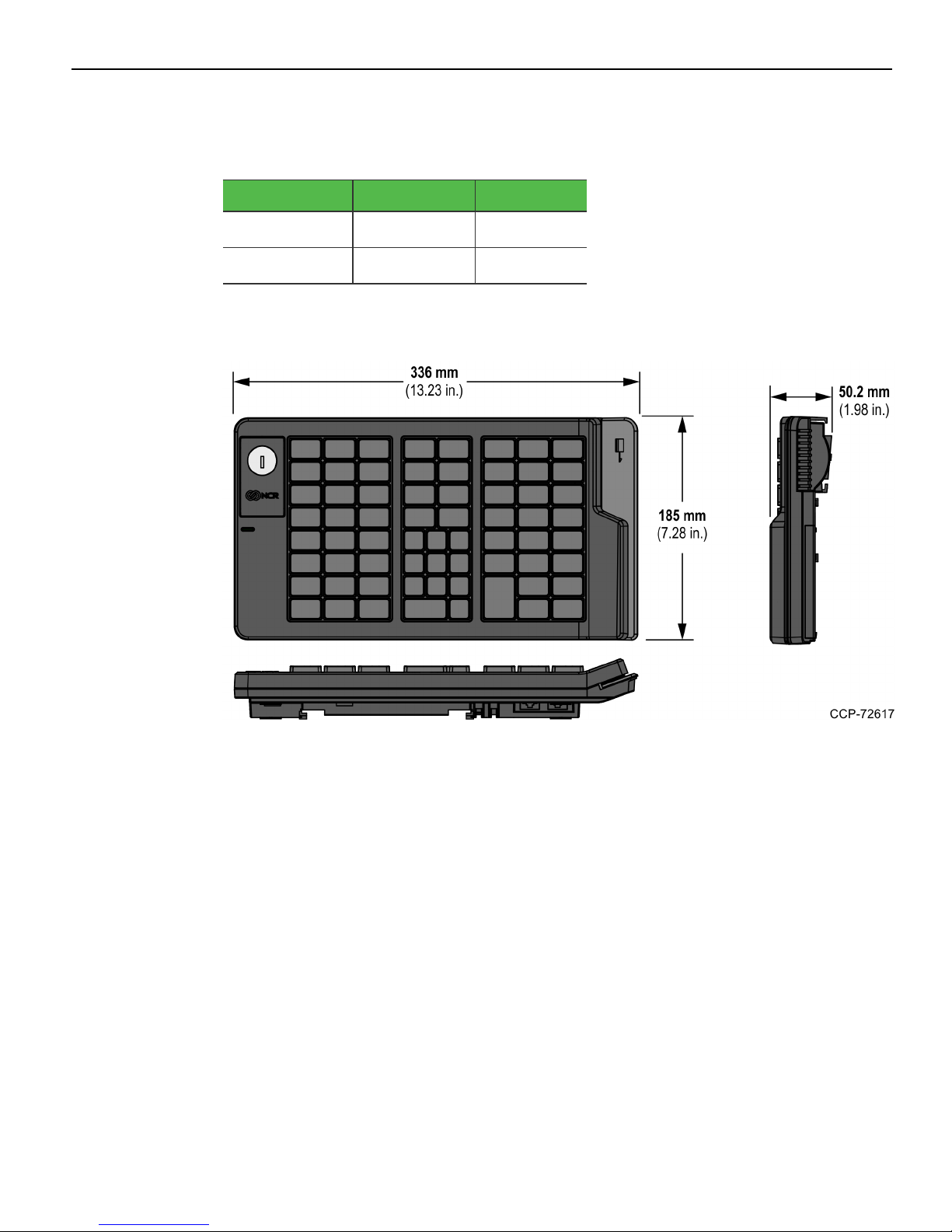
Dimensions
Weight
0.9Kg (1.98 lb)
Page 19

Hardware Installation 2-9
Cable Connection
A PS/2 or USB cable are required for use of the keyboard. The USB cable has a Standard
A plug on one end and the PS/2 cable has a PS/2 connector. Both cables have an RJ45 on
the opposite end. The PS/2 or USB Standard A plug is connected to the POS terminal
and the RJ45 connector is connected to the keyboard.
The keyboard also provides an additional RJ45 port to connect a peripheral device such
as a scanner or a cash drawer device attachment.
The following NCR cables can be used to establish connection between the
NCR 6932–6xxx 64–Key Keyboard and the POS terminal.
Part Number Description
1432-C792-0015 Cable, USB, 1.5 m, black
1432-C792-0040 Cable, USB, 4 m, black
1432-C793-0015 Cable, PS/2, 1.5 m, black
1432-C793-0040 Cable, PS/2, 4 m, black
Connect the cable to the appropriate RJ45 port and route the cable out of the keyboard
through the cable management features.
• Auxiliary—to connect serial devices
• Host—to connect to a POSterminal
Page 20

2-10 Hardware Installation
Powering up the Workstation
Caution: Before plugging in the keyboard, make sure to turn off the PC or POS
terminal. “Hot plugging” can result in damage to the PC or POSterminal due to the
increased power requirements of the keyboards.
1. Turn off the POS terminal.
2. Connect the keyboard to the appropriate port on the POS terminal.
3. Turn on the POS terminal.
Page 21

Hardware Installation 2-11
Key Tips and Lens Accessories
Key tip and lens accessories are included with each NCR6932 Keyboard.
Keyboard Model Accessories
6932-2202 • (1) key check sheet
• (56) 1.5x1-inch key tip lenses
• (3) 1.5x2-inch key tip lenses
6932-2302
6932-2201 • (1) key check sheet
6932-2301
• (1) 1x1-inch "00" keytip - Black (BLK7)
• (2) 1.5x2-inch keytip - Black (BLK7)
• (56) 1.5x1-inch key tip lenses
• (3) 1.5x2-inch key tip lenses
• (1) 1x1-inch "00" keytip - Beige (G11)
• (2) 1.5x2-inch keytip - Beige (G11)
Page 22

2-12 Hardware Installation
Key Check Sheet
The key check sheet included with the keyboard provides labels for customized keys on
the keyboard.
Tip: When placing labels on the key tips, make sure that the key tip is clean and dry.
Use tweezers to precisely position the labels on the key tips.
Page 23

Hardware Installation 2-13
Key Lenses
Key Lenses protect labels on key tips. When customizing cappable keys, key lenses and
customer–specified labels can be used. A label is placed on top of a cappable key to
identify the function or name assigned to that key. A key lens is then snapped onto the
top of the cappable key to cover the label.
Installing the Key Lens
Position the Key Lens over the Key Tip and then gently press the lens until it snaps and
locks into place.
Note: The snaps on the lens must be aligned with the indentations on the key tip.
Removing the Key Lens
To remove the Key Lens, slide any thin object under the corner of the Key Lens and
gently pop it off the Key Cap.
Page 24

2-14 Hardware Installation
Key Tip
The 1.5x2 key tip is used when two vertical adjacent POS function keys are configured
into a Double High Key. For more information on how to configure a Double High Key,
refer to Configuration on page17.
Installing a Key Tip
Place the Key Tip over its position on the keyboard and press the key until it snaps into
place.
Removing a Key Tip
Use a Key Removal Tool to remove a Key Tip from the keyboard.
Page 25

Hardware Installation 2-15
Insert the hands of the removal tool under each side of the Key Tip and carefully pull
the tool upward until the Key Tip pops off its retainer clips.
Page 26

2-16
Page 27

Chapter 3: Configuration
System Requirements
Before configuring the NCR 6932–2xxx 64-Key Keyboard, ensure that it is connected to
the POS terminal and ensure that the requirements listed below are met.
Operating System
NCR NCR 6932-2xxx 64-Key Keyboard requires either one of the following operating
systems:
• Linux
• POSReady 2009
• Windows 7
• Windows 10
Note: Contact the local NCR 6932-2xxx 64-Key Keyboard supplier for a copy of the
configuration software.
PS/2 Keyboard and MSR Driver Setup
When using the PS/2 Keyboard or Magnetic Stripe Reader (MSR) in Windows XP®
(POSReady 2009), Windows 7 (POSReady 7), and Windows 10 environments, make sure
to run the driver for the keyboard.
• PS/2 driver supports for 32–bit OS (Windows XP®, Windows 7 and Windows 10).
Therefore, it is NOT permitted to program PS/2 keyboards or MSR card readers that
are 64–bit OS.
• For USB keyboards or MSR card readers, as no driver is needed, it is permitted to
program USB devices under 32 bit or 64 bit OS.
Note: For more information, refer to Manual Setup of the Keyboard Driver in this
chapter.
Linux Environment
For Linux users, utilization of the Windows GUI is required to create the key map file.
Page 28

3-18 Configuration
Configuration Access
Utility Applications
The following Utility Applications can be downloaded, as appropriate for Operating
System, and used to configure the NCR6932-2xxx 64-Key keyboard.
Operating
System
Windows
Windows
Utility Application Description
Windows Command Line
Firmware Update Utility
Windows GUI Firmware
Update Utility
Windows Command Line
Configuration Utility
Windows Configuration
Utility (Matrix Maker)
A command line tool that updates
the firmware of the keyboard using
the command prompt.
A Graphical User Interface (GUI)
application that is used to update the
keyboard firmware.
A command line tool that flashes and
updates the keymap settings of a
keyboard using a .dat configuration
file created by the NCR Matrix Maker
utility.
Permits users to perform the
following during configuration:
• Detect the NCRRealPOS Compact
Linux
Linux GUI Configuration
Utility (Matrix Maker)
Alphanumeric (6932) Keyboard
• Set the keyboard configurations to
the flash memory in the keyboard
or RAM
• Set the keyboard to factory default
state
• Set the key mapping and/or
keyboard configuration with the
configuration data file
• Generate configuration data file
• Define the key mappings
• Define the keyboard configurations
• Define programmable keys
• Manage speaker control
Page 29

Configuration 3-19
Operating
System
Linux
Utility Application Description
Linux Command Line Flash
and Configuration Utility
Note: There are two
versions of this utility, one
each for a 32-bit system
and a 64-bit system. Make
sure to download the
correct version for your
system.
Downloading the Utility Applications
To install the NCR Matrix Maker utility, perform these steps:
1. Go the NCR website: http://www5.ncr.com/support/support_drivers_patches.asp.
A command line tool that updates
the firmware and keymap of the
keyboard using a command prompt.
2.
Select Retail Support Files (Drivers, Firmware, Operating Systems, Platform
Software (OPS/JavaPOS), BIOS, etc.).
3.
Select NCR RealPOS and SelfServ Peripherals (Firmware, Drivers, Utilities).
4.
Select Keyboards.
5.
Select 6932-2xxx (USB 64-Key, PS/2 64-Key).
6.
As appropriate for the Operating System, select the Utility file to download.
7. Follow the on–screen instructions to download the utility application.
Note: For concerns regarding the configuration software installation, please contact the
local NCR 6932–2xxx Keyboard supplier.
Page 30

3-20 Configuration
NCR Matrix Maker Utility
Installing the NCR Matrix Maker Utility
1. Run the NCR Matrix Maker installer. The NCR Matrix Maker setup is displayed.
2.
At the welcome screen, select Next. The following window is displayed.
3. Select Browse to specify the destination directory of the software to be installed, and
then select Next to continue.
Note: The default installation location of NcrMatrixMaker.exe is the following:
• For 32-bit operating systems, C:\Program Files\NCR Matrix
Maker\Programmable Keyboard
• For 64-bit operating systems, C:\Program Files (x86)\NCR Matrix
Maker\Programmable Keyboard
4. Select Next.
Page 31

Configuration 3-21
5. Select Next to start the installation process. When the software finishes the
installation, the Installation Complete window is displayed.
6.
Select Finish to exit the installation.
Page 32

3-22 Configuration
Menu Options
This section provides information on the functions of each menu option in the Matrix
Maker Utility. Refer to the following sections for functions and descriptions of the
Matrix Maker menu options:
• File
• Keyboard
• Diagnostic
File
This option permits the user to perform the following actions:
• New
• Category—takes the user back to the Keyboard Category window
• Keymap—refreshes the Matrix Maker utility and creates a new keymap
• Open—imports a Matrix Maker settings file.
Note: An error may occur if you choose a file of a newer version on the Matrix
Maker software with an older version.
• Save—saves all changes to the current Keymap file.
• Save As—permits user to save the current Keymap file with a new name.
• Exit—closes the Matrix Maker utility
Keyboard
This option provides the following actions that permit keyboard configuration
modifications:
• Update Whole Keyboard—sends the settings of the entire keyboard, which
includes the settings of the MSR, Keyboard, and Key Mapping.
• Update Key Mappings—This option enables the user to send the Key Map settings
to the keyboard.
• Retrieve Keyboard—This option enables the user to retrieve the data currently
programmed to the keyboard device, which includes the settings of the MSR,
Keyboard, and Key Mapping.
Caution: During the updating process, strictly follow these measures:
• Do not press any keys on the keyboard.
• Do not click the mouse.
• Do not touch the Touch panel.
• Write All to Flash—saves all configurations and key mapping to flash memory.
Page 33

Configuration 3-23
• RS232 Control—This window enables the user to modify RS232 control settings of
the keyboard.
• Keyboard Configuration—opens a window with three tabs that enable the user to
modify the configuration of the keyboard.
• General Parameters Tab—permits the user modify options for the following
parameters:
• Keylock data mode
• Numeric keypad layout
• Double key error detection
• Auto detection of blocking keys
• Speaker control parameters
• Keyboard, MSR, Touch, and USB setting on Keylock L position
• Ctrl+Alt+Del protection
• MSR and Keylock data modes
Page 34

3-24 Configuration
• MSR Control Tab—This tab enables the user to define options for MSR control.
Page 35

Configuration 3-25
• Blocking Keys Tab—This tab permits users to define options for blocking keys.
Note: Disable the auto detection of blocking keys before defining the blocking
keys options. The blocking keys option is only applicable when the auto
detection of blocking keys option is disabled. When the auto detection of
blocking keys option is enabled, the keyboard firmware during keyboard
operation dynamically defines the options.
• Sentinel Table—permits user to modify MSR, RS232, and keylock sentinels.
Warning: This section is for advanced users and developers. Improper
settings may cause an unexpected keyboard operation.
Page 36

3-26 Configuration
Diagnostic
• Enter Test Mode—enables the application to display the position of the key the key
is pressed.
• Press any key and the application shows the position of that key. This feature is
applicable only when testing the keyboard.
Note: If the keyboard provides the Keylock feature and the Repeat Enable option is
activated, the application continuously outputs the Keylock position to the terminal.
To stop this continuous output, press any other key.
• Exit Test Mode—enables the application to display the code program to a key when
the key is pressed.
• Load Factory Setting—reloads the default factory setting to the device.
Note: Re–plug the keyboard and close the software after successfully executing this
function.
• Reset—Resets the keyboard.
Note: This feature is applicable only when testing the keyboard.
• Firmware Version—displays the current version of the firmware.
• Get Status—displays the Keylock and drawer status of the device.
Page 37

Configuration 3-27
Using the Matrix Maker Utility
1. To launch the Matrix Maker Utility, do any of the following steps:
• From the Start menu, go to Start→All Programs→NCR Matrix Maker→NCR
Matrix Maker.
• Select the Matrix Maker icon in the desktop.
The Matrix Maker application displays the Keyboard Category window.
2. Select the keyboard to be programmed from the Available Product menu, and then
select OK.
Upon start–up, the application displays the initial window that includes menu
options and a virtual simulation of the programmable keyboard. To know the
assigned code(s) to a key, hover the mouse pointer over the key. The Code Legend
panel displays the code(s).
Page 38

3-28 Configuration
64–Key User Interface
Page 39

Configuration 3-29
Assign Code(s) to a Key using Key Code
Using the Key Code, you can map up to 256 codes to a single key position.
Caution: When assigning code(s) using the Key Code, remember the following
restrictions:
• Pay special attention when using the Shift, Alt, and Ctrl keys as they provide two
states: down and up.
Example: If the left Shift key is pressed once in the Virtual Keyboard area, the user gets
a down code which keeps the key in a down state. If this programming is kept, it would
behave as if the left Shift key was pressed down continuously.
• For USB interface, the following codes cannot be assigned with other codes. On the
other hand, if other code is assigned, the codes cannot be appended.
• <Wake>
• <Sleep>
• <Power>
• <Vol Up>
• <Vol Down>
• <Media Select>
• <Mail>
• <Calculator>
• <My Computer>
• <WWW Search>
Page 40

3-30 Configuration
To assign code(s) to a key using the Key Code, perform these steps:
1.
Select the key to program, and then select Key Code. The application displays the
following window.
The Key Code window enables the user to assign each key with a custom code(s).
• Mapping Sequence—displays the assigned code(s) in sequential order.
• Virtual Keyboard—displays a keyboard, which functions as an actual keyboard.
• Special Codes—displays the special codes that may not be included in the Virtual
Keyboard
2. To assign the code(s) for the selected key, do any of the following steps:
• Select the code from the Virtual Keyboard section, and then select OK.
• Select the code from the Special Codes section, and then select OK.
3. To update the keyboard with the assigned codes, do any of the following steps:
• From the main menu, select Keyboard→Update Key Mappings
• From the shortcuts toolbar, select the icon.
Saving the Keyboard Matrix
The keyboard assignments that are set using the Matrix Maker utility can be exported to
a DAT file. The DAT file serves as a backup and can also be used to update a keyboard to
the same configuration. To generate a DAT file for the current keyboard matrix set in
the Matrix Maker, follow these steps:
1.
From the main menu, go to File→Save As. The Save As window is displayed.
2. Browse to the folder in which to save the file.
3.
Input the file name, and then press Save.
Page 41

Configuration 3-31
Updating Keyboard Configuration Using a DAT file
The keyboard can be updated using a DAT file that is generated using Matrix Maker. For
more information about generating DAT files, refer to Saving the Keyboard Matrix on the
previous page.
To update the keyboard configuration using a DAT file, follow these steps:
1. Do one of the following steps:
• From the main menu, go to File→Open.
• Select the icon.
2. Browse to the folder where the DAT file is located.
3.
Select the file, and then select Open.
4. To update the keyboard, do any of the following steps:
• From the main menu, select Keyboard→Update Key Mappings
• From the shortcuts toolbar, select the icon.
Page 42

3-32 Configuration
Windows Command Line Configuration Utility
The Windows Command Line Configuration utility is a command line tool that flashes
and updates the keymap settings of a keyboard using a .dat configuration file created
by the NCR Matrix Maker utility.
To use the command line configuration utility, perform the following steps:
1. Install the Microsoft package for the Visual Studio 2010 runtime libraries included in
the download package.
Double-click the vcredsit_x86.exe file and follow the on-screen instructions.
2. Open a Command Prompt window as an Administrator.
Right-click on a Command Prompt shortcut→select Run As Administrator→select
Yes.
3. Navigate to the directory where the NCR-KeymapUpdate.exe file is located.
Note: Make sure that the HYHidLib.dll file included in the utility download
package is located in the same directory as the NCR-KeymapUpdate.exe file.
4. At the command prompt, enter the following command:
NCR-KeymapUpdate.exe <1 or 2> <DATfile name>
Where:
• 1 – indicates a 105-Key Compact Alphanumeric Keyboard
• 2 - indicates a 64-Key Keyboard
• DAT file name – indicates the file name of the keymap configuration file to be
installed to the keyboard. This file is created using the NCRMatrix Maker.
5. The window displays a command line to indicate a successful keymap update.
Page 43

Configuration 3-33
Windows GUIFirmware Update Utility
1. Connect the keyboard to a USBport.
2. Locate the HY_USB_FD.exe file specified during the Utility download.
3. Double-Click the HY_USB_FD.exe file to run and open the utility. The main window
displays and automatically detects the keyboard.
4. In the Firmware Download section, select ... to locate and select the firmware file to
be installed to the keyboard.
5. Select Download to flash and install the firmware to the keyboard.
6. Select OK after the firmware has been successfully installed.
7. Select Get FWVersion to retrieve and check the current keyboard firmware version.
Page 44

3-34 Configuration
Windows Command Line Firmware Update Utility
The Windows Command Line Firmware Update Utility is a command line tool that
updates the firmware of the keyboard using the command prompt.
To use the Windows Command Line Firmware Update utility, perform the following
steps:
1. Open a Command Prompt window as an Administrator.
Right-click on a Command Prompt shortcut→select Run As Administrator→select
Yes.
2. Navigate to the directory where the HY-FirmwareUpdate.exe file is located.
3. At the command prompt, enter the following command:
NCR-FirmwareUpdate.exe 2 <firmware file path>
Page 45

Configuration 3-35
Linux Command Line Flash and Configuration Update
Utility
The Linux Command Line Flash and Configuration Update Utility gets the current
keyboard firmware version and installs firmware and keymap updates to the keyboard
using a command prompt.
This utility has two versions, for a 32-bit system and a 64-bit system, make sure to use
the correct version for your system.
The "libusb" library is required to use Command Line Flash and Configuration utility.
To install the libusb library, perform the steps below:
1. Add the "oss" repository. Enter the following command:
zypper addrep
http://download.opensuse.org/distribution/11.4/repo/oss/ oss
2. Search if the libusb library is present or not in the oss repository. Enter the following
command:
zypper search --repo oss | grep libsub
3. Install the libsub0-1.0-devel library. Enter the following command:
zypper install libusb-1_0-devel
To upgrade the firmware and keymap or get the firmware version using this utility, run
the program as Root using the command format listed below.
• To upgrade the keyboard firmware, enter the following command:
./update 2 1 <firmware_bin_file_name>
Page 46

3-36 Configuration
Keyboard Physical Layout
The NCR NCR 6932-2xxx 64-Key Keyboard has the following physical layout:
• Default Configuration—uses double–wide zero key and double–high Enter key.
• Optional Configuration—uses two single–wide zero keys (“0” and “00”), and single–
high Shift F3 and Enter keys.
Default Configuration
Optional Configuration
Page 47

Configuration 3-37
Key Position Number
Note: The key position number is based on the IBM PS/2® keyboard standard key
position number, however, some keys are unique in keyboard which are P0~P31 and
N1~N7.
Page 48

3-38 Configuration
Unique POS Capabilities
The keyboard firmware supports the following POS–specific extensions to the standard
PC firmware:
• 32 Programmable POS Keys
• Numeric Keypad Layout
• Double High/Wide Keys
• Num Lock Operation
• Data Flash Subsystem
32 Programmable POS Keys
The NCR 6932-2xxx 64-Key Keyboard has 32 programmable keys that can be
programmed to generate any standard keyboard key.
The highlighted area on the image below is the programmable key section.
Page 49

Configuration 3-39
Numeric keypad layout
The layout of the numeric keypad on the keyboard can be switched from the traditional
“calculator” layout to a “telephone” layout.
Upon setting the Calculator/Telephone layout option flag in configuration data, the
keyboard firmware switches from the default “calculator” numeric keypad layout to the
“telephone” numeric keypad layout. If the host needs to restore the default “calculator”
layout, the Calculator/Telephone layout option flag is cleared in configuration data.
Note: Changing the numeric keypad layout also requires physically removing and
swapping the key caps on the first and third rows of the keypad. The key codes for the
numeric keypad are the same as those on a standard keyboard.
Page 50

3-40 Configuration
Double High/Wide Keys
Several keys on the keyboard can accept optional key tips that cover two keys to
produce double high or double wide keys. When a double high/wide key tip is pressed,
the keyboard firmware sends the key code for only one of the two keys.
In the following image, the bar on the keys indicates that a double high/wide keycap
may be installed on the two adjacent keys. The asterisk (*) symbol indicates key locations
that do not generate a key code when pressed simultaneously with another key.
The keyboard supports the following methods of double high/wide key operation:
1. Auto Detection of Double High/Wide Key (factory default state)
2. User configurable Double High/Wide Key by configuring of configuration data
Page 51

Configuration 3-41
Double Key Error Detection
All the keys in 64 Key POS keyboard have a double key error detection capability which
generates an error tone when two or more keys are depressed within 18mS.
When Double Key Error Detection is enabled and two or more keys are detected within
an 18 millisecond period, the keyboard firmware will indicate an error condition in the
same manner as a Buffer Overflow (01 Hex). The multiple keys detected within the 18
millisecond period will be ignored by the keyboard and not sent to the host system.
Only the Buffer Overflow Indication will be sent to the system.
In case auto detection of double height/wide key is enabled, if two keys are depressed
with 18mS and those two keys position is a valid blocking key pair, the keyboard will not
generate an error tone, instead, the keyboard firmware regards this as a blocked key
which is a double height/wide key.
When Double Key Error Detection is disabled, the keyboard firmware will not perform
Double Key Error Detection and will transmit all key entries. This allows for system
diagnostic and configuration software to receive two key codes for double size keys for
initialization of the keyboard. Once the double size keys are defined, the configuration
software will then activate the double key error detection feature while programming
the keyboard for Blocking Keys.
Num Lock operation
When the keyboard is reset or powered up, the firmware send the NUMLOCK make
and break codes to the terminal during the initialization. The firmware then monitors
for the terminal to turn on the NUMLOCKindicator by using the Set/Reset Mode
Indicator command.
During normal operation, when a key on the numeric keypad is pressed, the keyboard
firmware examines the current state of the NUM LOCK and performs one of the
following:
• NUM LOCK Flag Clear—the firmware sends the NUM LOCK make and break
keycodes, and then sends the make code for the depressed numeric key to the host.
• NUM LOCK Flag Set—the firmware simply sends the make code for the numeric
key pressed without sending a NUM LOCK keycode.
The NUM LOCK make or break code is sent before the code for each key on the
numeric keypad until the NUM LOCK indicator is turned on by the terminal.
Page 52

3-42
Page 53

Chapter 4: Maintenance and Troubleshooting
Safety Reminders
Carefully follow these safety requirements before servicing the keyboards.
• The keyboard does not contain any user serviceable parts and should only be
serviced by a qualified service technician.
• Before servicing the keyboard, plug your ground strap into a proper grounding
outlet. Failure to do so may damage it. Also, disconnect the power cord from the
POS terminal to which the keyboard is connected and disconnect the cables from
the POS terminal to the keyboard.
• To protect the internal circuitry from damage, unplug the power cord and then
momentarily press the power switch to drain the power supply capacitance.
• The power cord is used as the main disconnect device. Ensure that the socket outlet
is located or installed near the equipment and is easily accessible.
• The keyboard should only be powered by a Safety Extra Low Voltage (SELV) power
supply source with an available power level of 5 amperes or less, and suitable for the
country of installation. The power source must be certified by the appropriate safety
agency for the country of installation.
• If the peripheral does not have a fuse, it must be powered by an SELV power
supply source.
• If the peripheral has a fuse, replace only with the same type and ratings of fuse for
continued protection against risk of fire.
Page 54

4-44 Maintenance and Troubleshooting
Troubleshooting the Keyboard
NCR offers both on–site and mail–in service for the keyboard. Before calling for service
or mailing in your unit for repair, read the following troubleshooting tips to ensure the
keyboard needs repair. These tips include actions that can be used to correct specific
problems without the aid of a trained technician.
Note: For problems that are not listed in this section and those that are not resolved by
the suggested solutions, call for service.
Keyboard is not working
Probable Cause Possible Solution
The keyboard is not
powered.
The keyboard cable is
not connected.
The keylock is in “L”
position (LED green).
The keyboard is
defective.
Check the POS terminal power.
Connect the cable to the keyboard and connect
the keyboard cable to the keyboard port of the
POS terminal.
Turn the keylock to another position.
Call for service.
Some keys on the keyboard are not working
Probable Cause Possible Solution
The keyboard cable is
not connected.
The keyboard is
Connect the keyboard cable to the PC keyboard
port and to the back of the keyboard.
Reconfigure the keyboard through the
configured incorrectly.
The keyboard is “hot–
plugged” into the POS
terminal while the POS
terminal is powered on.
The keyboard is
defective.
configuration software.
Reboot the system.
Call for service.
Page 55

Maintenance and Troubleshooting 4-45
Numeric keypad is returning wrong keys
Probable Cause Solution
The numeric keypad is
not set up correctly.
The keyboard is
defective.
Speaker is not working
Probable Cause Solution
The speaker function is
not programmed
correctly.
The speaker harness is
not connected.
The keyboard is
defective.
Configure the keyboard numeric keypad for
either calculator or telephone layout.
Call for service.
Verify that the speaker settings are correct.
Call for service.
Call for service.
MSR is not working
Probable Cause Solution
The MSR card is not
oriented properly.
The keylock is in "L"
position.
The MSR is not
programmed correctly.
The MSR harness is loose
or broken.
The MSR is defective. Call for service.
Ensure that the magnetic stripe is oriented
properly.
Turn the keylock to another position.
Verify that the MSR settings are correct.
Call for service.
Page 56

4-46 Maintenance and Troubleshooting
Scanner is not working
Probable Cause Solution
An unsupported scanner
is connected to the unit.
The keyboard is
defective.
Keylock is not working
Probable Cause Solution
The keylock ribbon cable
is not connected.
The keylock is defective. Call for service.
Ensure that the scanner is a serial scanner.
Call for service.
Call for service.
Page 57

Maintenance and Troubleshooting 4-47
Cleaning the Keyboard
Perform the following actions to clean keyboard:
1. Turn off the POS terminal properly.
2. Unplug the cable from the keyboard.
3. Spray liquid cleaner (such as window cleaner spray or a product designed for
cleaning office computer equipment) onto a soft cloth to wipe the keys and keyboard
housing clean.
Caution: Do not spray liquid cleaners directly onto the keyboard.
4. Let the keyboard dry completely.
5. Use either a canned air type office supply cleaning equipment or a small vacuum to
remove dust or foreign objects between the keys.
6. Plug in the keyboard cable. Keyboard is now ready for use.
Page 58

4-48 Maintenance and Troubleshooting
Cleaning the MSR
MSR Cleaning Cards and MSR Treatment Cards may be purchased from NCR-Direct at
http://www.ncr-direct.com. Customers who are participating in the NCR Partnership
Services Program can also purchase cards through NCR Services using the NCR Part
Numbers.
MSR Cleaning and Treatment Cards
Part Part Number NCR Part Number
MSR Cleaning Card, Dry 998-0052929
MSR Cleaning Card, Wet 520522 603-9014730 (box of 50)
MSR Treatment Card 9346-2446 497-0453056 (box of 20)
MSR Treatment Card
The MSR Treatment Card is used to assist in protecting Magnetic Stripe Readers from
Electrostatic Discharge (ESD), which can cause failures when swiping cards that have
metallic hologram stripes.
Swipe the card through the MSR in a smooth motion. Only swipe it down ONCE and
up ONCE. Allow the device to dry for 5 minutes before swiping any other cards.
For two–headed readers, swipe the card through one head, turn the card over, and then
swipe through the other head.
Note: Each long side of the card may be used twice. Each short side of the card may be
used only once. Thus, a single card can treat 6 MSR devices with one UP and one
DOWN swipe per MSR device. These limits should not be exceeded due to the
possibility of spreading contaminants from machine to machine and/or reducing ESD
protection.
Note: If all six up/down swipes are not used on a fresh card it should be placed in a
sealed (Ziploc) bag for future use.
Page 59

Maintenance and Troubleshooting 4-49
Cleaning and Treatment Frequency
New MSR
Prior to placing in operation, the MSR device should be swiped with the MSR
Treatment Card.
Existing MSR
An existing MSR should be cleaned using an MSR Cleaning Card before treating it with
a MSR Treatment Card. For low use retail establishments, the cleaning and treatment
procedures should be followed at least once per month. In areas of extremely high
traffic (in excess of 500 swipes per day) or an operating environment that is high in
contaminants, such as found in the food service industry, a weekly cleaning and
treatment should be performed.
Page 60

4-50
 Loading...