

NCR 6932-2202-9090, 6932-2302-9090, 6932-2201-9090, 6932-2301-9090 User Manual
User Guide
NCR RealPOS 64-Key (6932) Keyboard
Release 1.0
BCC-0000-5224
Issue A

The product described in this document is a licensed product of NCR Corporation.
NCR is a registered trademark of NCR Corporation. NCR RealPOS is a trademark of NCR Corporation in
the United States and/or other countries. Other product names mentioned in this publication may be
trademarks or registered trademarks of their respective companies and are hereby acknowledged.
Where creation of derivative works, modifications or copies of this NCR copyrighted documentation is
permitted under the terms and conditions of an agreement you have with NCR, NCR's copyright notice
must be included.
It is the policy of NCR Corporation (NCR) to improve products as new technology, components,
software, and firmware become available. NCR, therefore, reserves the right to change specifications
without prior notice.
All features, functions, and operations described herein may not be marketed by NCR in all parts of the
world. In some instances, photographs are of equipment prototypes. Therefore, before using this
document, consult with your NCR representative or NCR office for information that is applicable and
current.
To maintain the quality of our publications, we need your comments on the accuracy, clarity,
organization, and value of this book. Please use the link below to send your comments.
Email: FD230036@ncr.com
Copyright © 2018
By NCR Corporation
Duluth, GA U.S.A.
All Rights Reserved

Preface
Audience
This book is written for hardware installer/service personnel, system integrators, and
field engineers.
Notice: This document is NCR proprietary information and is not to be disclosed or
reproduced without consent.
Radio Frequency Interference Statements
Federal Communications Commission (FCC)
This equipment has been tested and found to comply with the limits for a Class A digital
device, pursuant to Part 15 of FCC Rules. These limits are designed to provide
reasonable protection against harmful interference when the equipment is operated in a
commercial environment. This equipment generates, uses, and can radiate radio
frequency energy and, if not installed and used in accordance with the instruction
manual, may cause harmful interference to radio communications. Operation of this
equipment in a residential area is likely to cause interference in which case the user will
be required to correct the interference at his own expense.
i
NCR is not responsible for any radio or television interference caused by unauthorized
modification of this equipment or the substitution or attachment of connecting cables
and equipment other than those specified by NCR. The correction of interference
caused by such unauthorized modification, substitution or attachment will be the
responsibility of the user. The user is cautioned that changes or modifications not
expressly approved by NCR may void the user’s authority to operate the equipment.
Canadian Department of Communications
This Class A digital apparatus complies with Canadian ICES-003.
This digital apparatus does not exceed the Class A limits for radio noise emissions from
digital apparatus set out in the Radio Interference Regulations of the Canadian
Department of Communications.
Cet appareil numérique de la classe A est conforme à la norme NMB-003 du Canada.
Le présent appareil numérique n'émet pas de bruits radioélectriques dépassant les
limites applicables aux appareils numériques de la classe A prescrites dans le règlement
sur le brouillage radioélectriques édicté par le ministrère des Communications du
Canada.
ii
Voluntary Control Council For Interference (VCCI)
International Radio Frequency Interference Statement
Warning: This is a Class A product. In a domestic environment this product may
cause radio interference in which case the user may be required to take adequate
measures.

Out of Box Failure (OBF)
If you experience an out of box failure (OBF) during installation or staging related to a
missing, wrong or defective unit or item, simply provide NCR with a detailed
description of the issue and the item will be replaced free of charge. For assistance with
this process send an email to CustomerSat.Retail@ncr.com with the following details:
• NCR Sales Order # (Sales Order # are located on the box)
• Date of Product Installation
• Product Model #
• Unit Serial #
• NCR part # of defective/missing/wrong component
• Description of Failure (please be specific. For example: “display will not power on”)
• Customer/Requestor’s contact name, phone number and/or e-mail address
• Address to ship replacement part(s)
iii
Warranty
Transport the product in its original packaging to prevent impact damages.
If you do not have access to a computer, you may leave a voice message at: 1-800-5288658 (USA), or (International) +1-770-623-7400. When leaving a message, please provide a
phone number and/or an email address so NCR can contact you if additional details are
needed.
Note: Used equipment that experiences a failure does not qualify as an OBF and should
go through the NCR warranty process.
Warranty terms vary by region and country.
All parts of this product that are subject to normal wear and tear are not included in the
warranty. In general, damages due to the following are not covered by the warranty.
• Improper or insufficient maintenance
• Improper use or unauthorized modifications of the product.
For detailed warranty arrangements please consult your contract documents.

iv
Returning Defective Hardware for Service
Use the following procedure to report/return defective hardware.
Call the NCR Customer Care Center at 1-800-262-7782 and have the following information
available when you place the call.
• Class/Model number of the defective equipment
• Serial Number of the defective equipment
• Equipment location in the store
• Description of the problem, including any system error codes, error condition, or
guidance to the area of failure.
The NCR Agent will provide you with a work order number, which serves as your
Return Material Authorization (RMA). Please provide the RMA on the outside of the
shipping box.
Note: A work order must be opened for each device that is shipped for repair.

Table of Contents
Chapter 1: Product Overview
Introduction 1
Model Numbers 2
Features 2
Extra Ports 2
Keylock 3
Speaker 4
System Status Indicators 4
v
Magnetic Stripe Reader 5
Chapter 2: Hardware Installation
Environmental Conditions 7
Physical Environment 7
Operating Range 7
Storage Range 7
Transit Range 7
Electrical Environment 8
Dimensions 8
Weight 8
Cable Connection 9
Powering up the Workstation 10
Key Tips and Lens Accessories 11
Key Check Sheet 12
Key Lenses 13
Installing the Key Lens 13
Removing the Key Lens 13
Key Tip 14
Installing a Key Tip 14

vi
Removing a Key Tip 14
Chapter 3: Configuration
System Requirements 17
Operating System 17
PS/2 Keyboard and MSR Driver Setup 17
Linux Environment 17
Configuration Access 18
Utility Applications 18
Downloading the Utility Applications 19
NCR Matrix Maker Utility 20
Installing the NCR Matrix Maker Utility 20
Menu Options 22
File 22
Keyboard 22
Diagnostic 26
Using the Matrix Maker Utility 27
Assign Code(s) to a Key using Key Code 29
Updating Keyboard Configuration Using a DAT file 31
Windows Command Line Configuration Utility 32
Windows GUIFirmware Update Utility 33
Windows Command Line Firmware Update Utility 34
Linux Command Line Flash and Configuration Update Utility 35
Keyboard Physical Layout 36
Default Configuration 36
Optional Configuration 36
Key Position Number 37
Unique POS Capabilities 38
32 Programmable POS Keys 38
Numeric keypad layout 39
Double High/Wide Keys 40
Double Key Error Detection 41

Num Lock operation 41
Chapter 4: Maintenance and Troubleshooting
Safety Reminders 43
Troubleshooting the Keyboard 44
Keyboard is not working 44
Some keys on the keyboard are not working 44
Numeric keypad is returning wrong keys 45
Speaker is not working 45
MSR is not working 45
Scanner is not working 46
Keylock is not working 46
Cleaning the Keyboard 47
vii
Cleaning the MSR 48
MSR Cleaning and Treatment Cards 48
MSR Treatment Card 48
Cleaning and Treatment Frequency 49
New MSR 49
Existing MSR 49

viii
Revision Record
Issue Date Remarks
A
Jan 2018 First Issue
Chapter 1: Product Overview
Introduction
The NCR 6932-2XXX 64–Key Keyboard is designed for Point–of–Service (POS)
applications. This keyboard connects to either a PS/2 or a USB port of a computer. It
includes 56 assignable function keys, which are programmable.
The fifty–five keys are blank from the factory and must be programmed using the
Matrix Maker Utility. To download the utility, follow these steps:
1. Go to the NCR Web Site: http://www.ncr.com.
2.
Select the Support tab.
3.
Select Drivers and Patches → Retail Support Files → NCR RealPOS and
SelfServ Peripherals → Keyboards → 6932‐2XXX.

1-2 Product Overview
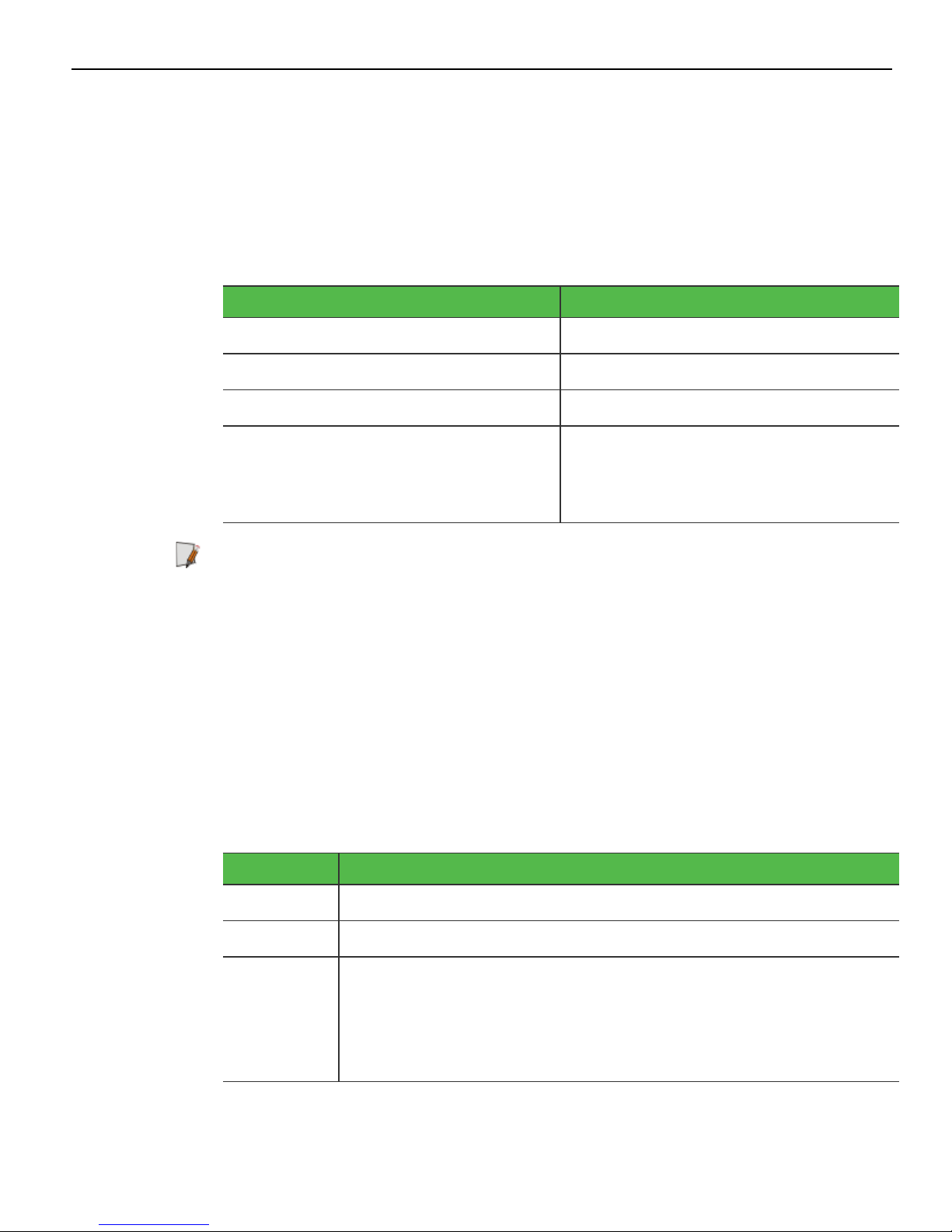
Model Numbers
Product ID Description
Features
6932-22029090
6932-2302-
NCR RealPOS 64-Key POS Keyboard, Keylock, No MSR
(Black)
NCR RealPOS 64-Key POS Keyboard, Keylock, MSR (Black)
9090
6932-22019090
6932-2301-
NCR RealPOS 64-Key POS Keyboard, Keylock, No MSR
(Beige)
NCR RealPOS 64-Key POS Keyboard, Keylock, MSR (Beige)
9090
This section provides information on available features for NCR 6932 64–Key keyboard.
Standard features
• POS matrix layout
• Numeric keypad
• 56 POS function keys
Extra Ports
• LED status indicator
• RS-232 scanner port
Optional features
• 4-position key lock
• 3-track ISO MSR
• PS/2 or USB cable
An extra serial port underneath the keyboard allows customers to connect any
peripheral device such as a scanner or a cash drawer.
When the keylock is in “L” position, the MSR and serial port can be disabled or enabled
by keylock configuration option under software control.
Note: When the keyboard disables the serial port, the keyboard cuts OFF the power
line for the serial device.

Product Overview 1-3
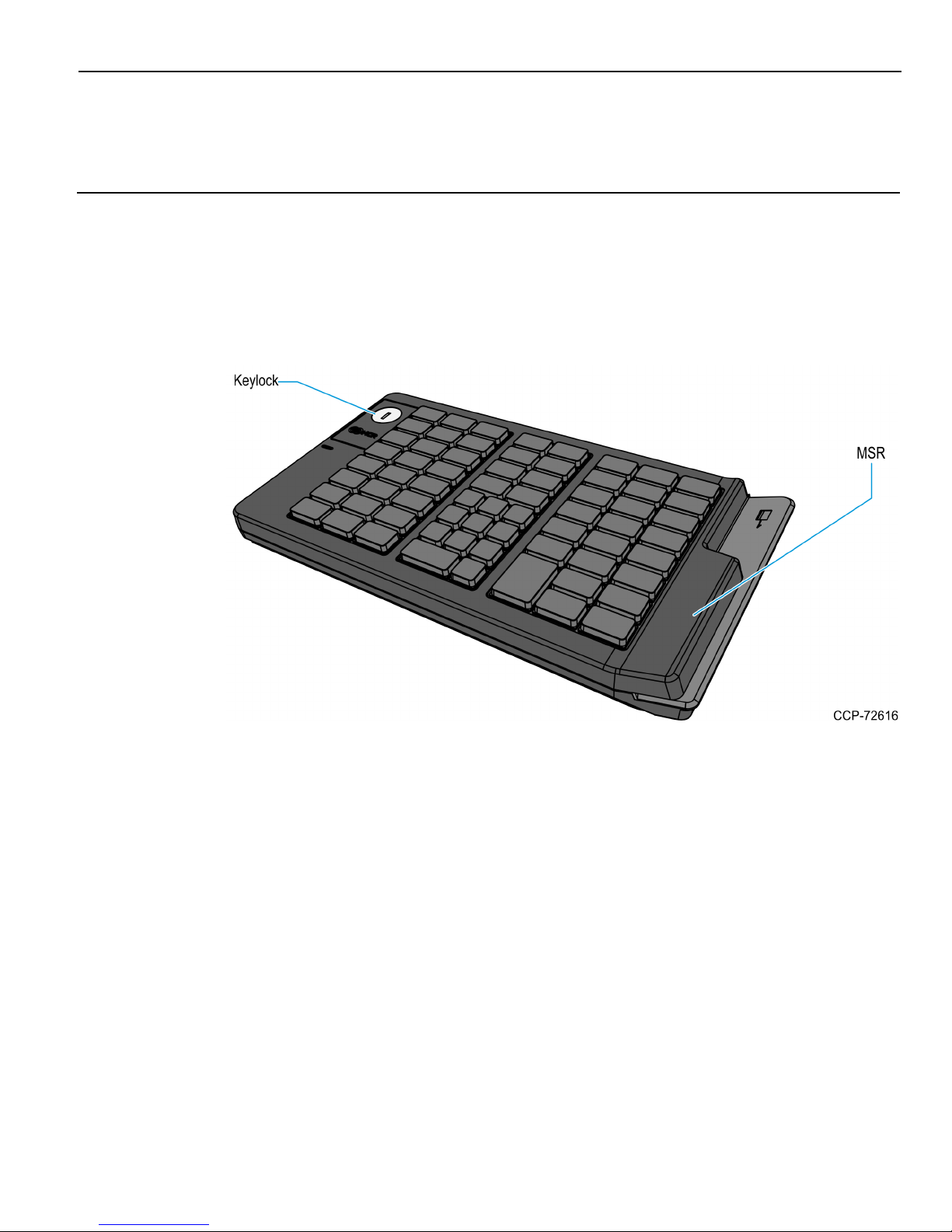
Keylock
The keyboard may include 4–position Keylock. The Keylock switch can be rotated
between specific positions by using 3 keys. These keys provide differential access to
keyboard functions.
The following table explains the keyboard positions.
Abbreviation Position Description
Ex Exception Allows customers or service representatives to
perform low–level programming such diagnostics,
configuration, and loading of the POSterminal
L Locked Locks keyboard input to prohibit use of normal
functions. It can also be programmed to lock or
not lock the MSR, and external USB port. The
default setting is to lock all of those devices.
R Register Allows normal retail mode functions
S Supervisor Allows supervisors to provide the highest level of
POS terminal control such as refunds and running
totals
The following table explains the keys used for the keylock.
KeyLabel Description
Ex Can be inserted and removed only in the “Locked” position and
allows the keylock to be moved only to the “Exception” position.
R Can be inserted and removed from the “Locked” or “Register”
positions and allows the keylock to be moved between these
positions. This key is often used by operators to lock the
keyboard when leaving the station.
S Can be inserted and removed only in the “Locked” and “Register”
positions. This key allows access to the “Supervisor” position but
not to the “Exception” position. This key is typically used by store
supervisors to perform supervisory functions.
1-4 Product Overview
Speaker
The programmable speaker provides audible key clicks and error tones for feedback in
both integrated and modular configurations. Keyboards are often located remotely from
the POS terminal. Thus, an integrated keyboard speaker is important for maximum
productivity.
The following table shows the speaker characteristics.
Characteristic Standard
Resonant Frequency 600±20% Hz
Frequency Range 600 to 20,000 Hz
Power Rating 0.5 W
Sound Pressure Level
(at the power level of 0.5 W and the
distance of 0.5 meter)
Note: The user programmable speaker tone function on the USB keyboards is not
supported when the keyboard is connected to a standard PC. The standard PC keyboard
voltage tolerance is not sufficient to handle the extra power requirements of the
programmable speaker tone. Only the default key click and error tones are supported
on a PC.
System Status Indicators
This feature provides the present state of the keyboard. The indicator is a dual color
Red/Green LED. A signal from the keyboard microcontroller selects the status of the
LED.
The following table explains the LEDcolors and their corresponding status indication.
LED Color Description
85±2 dBA
(at 0.8kHz, 1.0kHz, 1.2kHz, and
1.5kHz)
Green The system is generally working properly
Off The system is Off.
Alternately
Flashing
Green and
Red
The keyboard is in the special PCSETUP mode.
Note: In PCSETUP mode, the keyboard is used to run PC
setup routines such as PCBIOS and other configuration or
diagnostics software.

Product Overview 1-5
Magnetic Stripe Reader
The Magnetic Stripe Reader (MSR) is an optional feature that provides support for
reading magnetically coded data cards. The NCR 6932 keyboards support a 3–track ISO
MSR.

1-6
Chapter 2: Hardware Installation
Environmental Conditions
This section lists the physical and electrical environments required for the NCR 69322XXX 64–Key Keyboard.
Warning: Condensation may occur when keyboard is transferred from cold areas to
warm areas during shipment. If condensation has occurred, ensure that the
keyboard has undergone a drying process before its use.
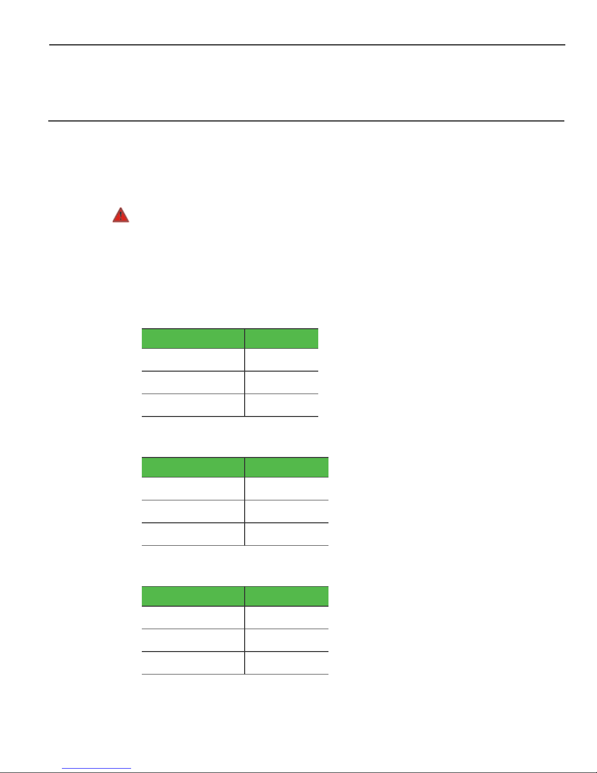
Physical Environment
Operating Range
Condition Range
Temperature 0ºC to +45ºC
Relative Humidity 10% to 90%
Dew Point 26ºC
Storage Range
Condition Range
Temperature -10ºC to +50ºC
Relative Humidity 10% to 90%
Dew Point N/A
Transit Range
Condition Range
Temperature -40ºC to +60ºC
Relative Humidity 5% to 95%
Dew Point N/A
2-8 Hardware Installation
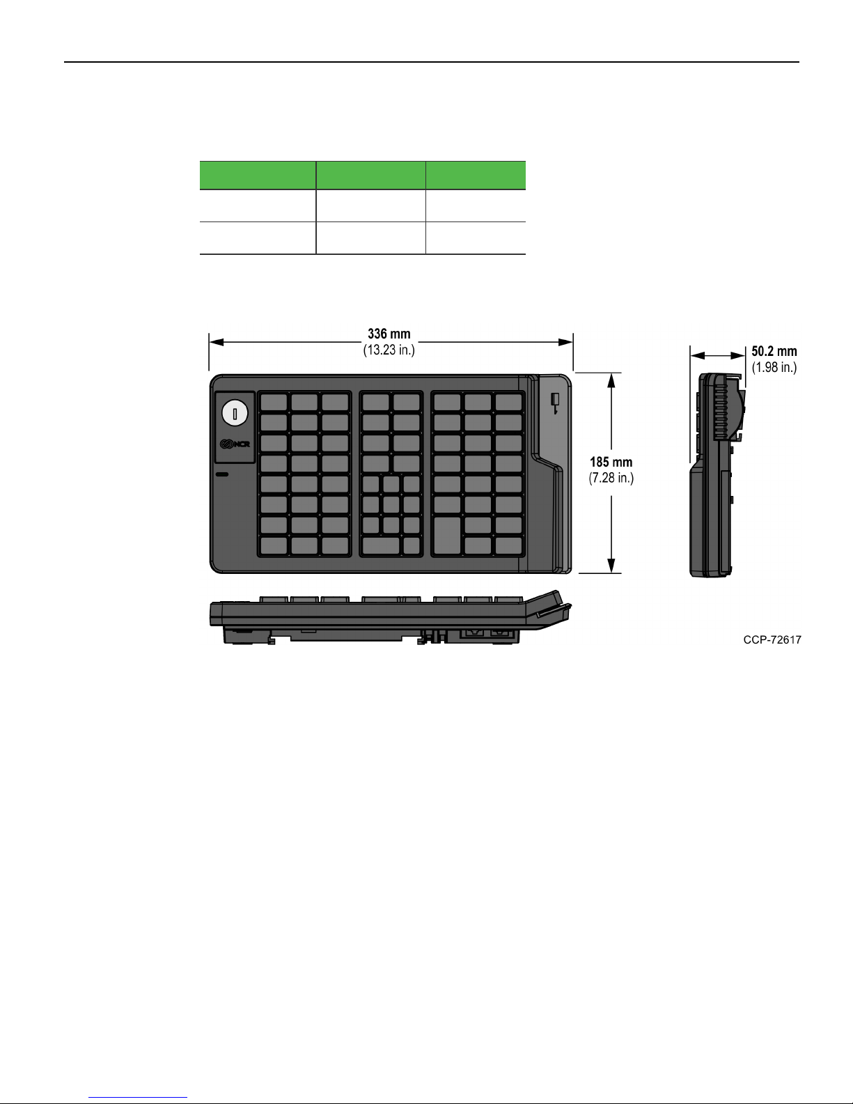
Electrical Environment
The electrical environment required for the keyboard module is listed as follows:
PS/2 USB
Power Supply +5V/DC±10% +5V/DC±5%
Current Input <500mA <500mA
Dimensions
Weight
0.9Kg (1.98 lb)
 Loading...