

Page 1

NCR 5992 Signature
Capture Plus
Release 1.0
User's Guide
B005-0000-1108
Issue C
Page 2

The product described in this book is a licensed product of NCR Corporation.
IBM is a registered trademark of International Business Machines, Inc.
It is the policy of NCR Corporation (NCR) to improve products as new technology, components, software,
and firmware become available. NCR, therefore, reserves the right to change specifications without prior
notice.
All features, functions, and operations described herein may not be marketed by NCR in all parts of the
world. In some instances, photographs are of equipment prototypes. Therefore, before using this document,
consult with your NCR representati ve or NCR office for information that is appl icab l e and current.
To maintain the quality of our publications, we need your comments on the accuracy, clarity, organization,
and value of this book.
Address correspondence to:
Retail Solutions Group−Atlanta
NCR Corporation
2651 Satellite Blvd.
Duluth, GA 30096
Copyright © 2000
By NCR Corporati on
Dayton, Ohio U.S.A.
All Rights Reserved
Page 3

Table of Contents
Chapter 1 Overview
Introduction..................................................................1-1
Physical Description.....................................................1-2
5992 Model Configurations..........................................1-2
Security....................................................................1-2
5992 Signature Capture Unit .................................1-3
Stylus.......................................................................1-3
Interface Cable........................................................1-3
Power Module ........................................................1-4
Functional Descripti o n.................................................1-4
Communi catio n Int e r face.............................................1-5
EIA-232....................................................................1-5
IBM-EIA-485...........................................................1-6
User's Gui de i
Chapter 2 Available Softwa re
Software Products.........................................................2-1
Chapter 3 Installation
Hardware Considerations ............................................3-1
5992 Unit Location..................................................3-1
Power Considerations..................................................3-2
Power Modules.......................................................3-2
Auxiliary P owe r Cable...........................................3-2
Environmental Considerations....................................3-3
Unpacking...............................................................3-3
Inspection................................................................3-3
Inventory.................................................................3-4
Installation ..............................................................3-4
Page 4

ii User's Guide
Connecting and Disconnecting the NCR 5992
Stylus and Host Cable ............................................3-5
Connecting the NCR 5992 to the NCR 7452/3
Workstation...................................................................3-8
Cable Configurations.............................................3-8
Connecting the NCR 5992 to a PC.......................3-12
Chapter 4 Operational Modes
Introduction..................................................................4-1
Normal Mode................................................................4-1
Supervisor Mod e..........................................................4-3
Startup Sequence....................................................4-3
Operation................................................................4-5
Menu Flow..............................................................4-6
Supervisor Me n u It ems..........................................4-6
Maintenance Mode.....................................................4-18
Perfo r ming a Set up...............................................4-18
Perfo r ming Diag n o st ics .......................................4-2 0
Loading the Operating System............................4-21
Chapter 5 Troubleshooting
Introduction..................................................................5-1
Simple Troubleshooting Guide.............................5-1
Detailed Problem Troubleshooting.............................5-2
Chapter 6: Diagno stics Spe cif ication
Introduction..................................................................6-1
Startup Sequence....................................................6-1
Operation................................................................6-4
Menu Flow..............................................................6-5
Keypad Test............................................................6-6
Display Test............................................................6-7
Page 5

MSR Test .................................................................6-7
IBM 46xx Test..........................................................6-9
Host RS232 Test.................................................... 6-10
AUX1A RS232 Test...............................................6-13
AUX1B RS232 Test ............................................... 6-16
SRAM Test............................................................6-19
Encryption Test.....................................................6-20
Security Menu.......................................................6-20
OS Version............................................................6-31
Library Version.....................................................6-31
Security Version....................................................6-32
Digitizer Version ..................................................6-32
Calibrate................................................................6-33
Stylus Test.............................................................6-36
LCD Contrast........................................................6-36
Show Touches.......................................................6-37
Base Line/Gain..................................................... 6-38
Show Keypad Touches.........................................6-38
User's Guide iii
Chapter 5 Index
Page 6

iv User's Guide
Page 7

User's Gui de v
Revision Record
Issue Date Remarks
A Apr 99 First issue
BOct 99Revision
C July 00 Added K150 security and IVI Checkmate Keyfac
support in Chapter 6.
Page 8

vi User's Guide
Radio Frequency Interference Statements
Federal Communications Commission (FCC)
Information to User
This equipment has been tested and found to comply with the limits for a Class A
digital device, pursuant to Part 15 of FCC Rules. These limits are designed to provide
reasonable protection against harmful interference when the equipment is operated in
a commercial environment. This equipment generates, uses, and can radiate radio
frequency energy and, if not installed and used in accordance with the instruction
manual, may cause harmful interference to radio communications. Operation of this
equipment in a residential area is likely to cause interference in which case the user
will be required to correct the interference at his own expense.
NCR is not responsible for any radio or television interference caused by unauthorized
modification of this equipment or the substitution or attachment of connecting cables
and equipment other than those specified by NCR. The correction of interference
caused by such unauthorized modification, substitution or attachment will be the
responsibility of the user. The user is cautioned that changes or modifications not
expressly approved by NCR may void the user’s authority to operate the equipment.
Canadian Department of Communications
This digital apparatus does not exceed the Class A limits for radio noise emissions
from digital apparatus set out in the Radio Interference Regulations of the Canadian
Department of Co m muni cat ion s .
Le p rése nt ap p are il numér ique n’émet p as de b ruit s rad ioélectri ques dépa ssan t les
limites applicables aux appareils numériques de la classe A prescrites dans le
Règlement sur le brouillage radioélectriques édicté par le ministrère des
Communications du Canada.
Voluntary Control Council For Interference (VCCI)
Page 9

Introduction
1-1
Chapter 1 Overview
The NCR 5992 Signature Capture Plus unit is designed to speed up
credit card and other payment methods in the point of service (POS)
environment. Your customers use a stylus to authorize transactions
without paperwork. The transaction data and signatures are stored
electronically.
Controlled by an application running on your PC-based host
workstation, the 5992's high resolution graphics screen can also display
any of the following and more:
• Credit receip t s
• Void and return slip s
• Car rental forms
• Extended warranty agreements
• Customer surveys
• Animate d adv ert ising and promot ion a l messages
An MSR option allows easy entry of magnetic stripe card data, and a
PIN entry option lets your customers enter their personal identification
numbers under secure conditions.
Page 10

1-2 Overview
Physical Description
The basic 5992 includes the signature capture unit, a stylus assembly,
an i nterfac e cabl e, and a p ower module, as sh own bel ow.
To RS-232 Port
on workstation
5945 RS-232 (9-Pin D shell) Cable
(5992-K010-V001)
5992 Signature Capture Terminal
(5992-K100-V001)
5945 Power Cable Adapter
(5992-K021-V001)
16649
Warning: The 5992 terminal cannot be opened for any reason.
5992 Model Configurations
Security
The NCR 5992 is a secure model that provides encryption functions for
secure PIN entry and processing of debit transactions, PIN numbers,
and similar input.
Page 11

Overview 1-3
Encryp t ion key codes an d oth e r se curity factors a r e se t at t h e facto r y.
Special encryption keys are set by your system administrator or local
clearing fina n cia l in stitutio n . A cabin et se cu rit y interlock prev ent s
unauthor ize d a ccess to random access memory (RAM ) co n tain in g the
encrypti on key code s.
Opening the cabinet erases the 5992 system RAM contents, requiring
the software and encryption keys to be reloaded.
5992 Signature Ca ptur e Uni t
The 5992 signature capture unit is housed in an injection-molded
thermoplastic cabine t . The physical spe cificat io n s are:
• Weight - Installed: 28 oz (0.81 kg)
• Width: 8.5 in. (21.6 cm)
• Depth: 7.5 in. (19.1 cm)
• Height: 2.75 in. (6.98 cm)
• 320 by 240 pixel supertwist LCD display
• Active display area: 4.5 in. (11.4 cm) by 3.4 in. (8.6 cm)
Stylus
The stylus is a t t ached to a lightweigh t , fle x ible , 27.5-inch (69.8 cm)
cable that connects it to the 5992.
Interf ace Ca bl e
The communications interface cable connects the 5992 signature
capture unit to the host workstation via EIA_232. It includes a
connector fo r t h e p owe r mo dule DC cable.
Page 12

1-4 Overview
Power Module
The power module is a Class 2 power supply. It includes an ac plug
that connects to the wall outlet, plus a cable that supplies +12 volts DC
to the 5992.
Functional Description
The 5992 combines a graphic liquid crystal display (LCD) with a
transparent digitizer. This combination permits your customer to sign
a displayed image of a credit card form or other mu lti-line form. This
signature image is then digitized and supplied to the host workstation
for processing.
The electron ic signatur e cap ture capability a n d the abilit y t o display
high-resolution graphics are innovative features of the 5992. These
features bring new dimensions to the operation of your business and
service to your customers. Also, the customer display reduces system
costs by replacing the customer display of the host workstation.
As a customer display, the 5992 displays up to 30 lines of 40 characters
each. It also displays forms, surveys, or high-resolution graphic images
such as promo tio n a l messages ta rge t e d to in -st ore cus t o m e rs. In
addition, the 5992 has a magnetic stripe reader (MSR) for credit/debit
card data entry.
The 5992 operates with any host workstation or processor that has
EIA-232 interface. The host is loaded with an application program that
implements the features and functions of the 5992.
The operation of the 5992 is controlled by commands and data sent to it
from the application software running in the host workstation. The
application software:
• sends transaction data
• downloads cre d it slip graphics data fo r disp la y
• downloads forms or surveys for display
• downloads g r aph ic d at a files o r tex t for pr omot io n al d isp la ys
Page 13

• collects the cust ome r 's signatu re.
• prints the signature on the customer's receipt
• handles storage of the electronic transaction record and signature
Typically, promotional display da t a files a re dev elo p e d on the sys t em
processor or a person al co mputer (PC ), us ing a comm e rcia lly available
graphics software package. These graphic data files are formatted
using the WinForm utilit y , a n d th e n downloaded from the h ost
workstation and stored in the 5992.
The 5992 is loaded with its operating system at the factory, and is
delivered in a fully function a l con d it ion . A lith iu m ba t te ry provides
memory rete ntion v o lta ges for a ll R AM loca tio n s .
Communication Interface
The NCR 5992 communicates with a host workstation using one of two
interfaces: EIA-232 or IBM-EIA-485. The interface cable used dictates
the communication type.
Overview 1-5
An interface cable provides the required electrical conductors for
signals between the host workstation and the 5992. Although two
different cables are availa ble; the one supplied is for the
commun ica t ions type specified in your order.
EIA-232
EIA-232 protocol transmission is a synchronous, half duplex. The data
format is 7, 8 or 9 data bits, parity or no parity, and one stop bit. Baud
rates up to 38.4 Kbps are supported by the device. However, the NCR
diagnostics and utilities only supports up to 19.2Kbps. The 5992 can
either manually select or automatically detect the host data rate.
Page 14

1-6 Overview
IBM-EIA-485
The 5992 supports the future release of the IBM EIA-485 protocol for
direct connection to an IBM 468x terminal. The EIA-485 interface
supports a 187,500 bps data rate using half-duplex, asynchronous
mode. The data format is eight data bits, one start bit, one poll/select
bit and two stop bits.
Page 15

Chapter 2 Available Software
Software Products
The software available for the NCR 5992 is provided on 3.5" DOS
diskett es. Th is s o ft ware in clu d es the fo llowing products:
• 5991/2 Utilities (not available in Canada)
(Order number G370-1123-0100):
• 5991 unit test utility
• WINFORM. EXE (A Windows-based utility t hat co m bines the
advertisement screen generator and forms screen generator)
• Security k ey loa de r utilit y
2-1
1
• 5992 platform operating system load file
• 5992 platform host command processor (HCP) application load
file
• 5991/2 host sample source code (G370-1124-0100):
• Sample application in IBM 4 6 83 BA SIC
• Sample application in C for 5991 with dedicated host
• Developer Program Interface (DPI) support module, which
provides an interface to each function code supported by the
5991
1The security key loader is not usable with 5991-05xx models or any of the 5992 models.
Page 16

2-2 Available Software
• Communication module, which provides the RS-232
communications interface to the 5992
• Utility m od u le, which provides s ample program interfa ce
routines to the 5992
Further inform a t ion about this soft wa re is provided in the
Guide, B005-0000-1107.
Developer's
Page 17

3-1
Chapter 3 Installation
The NCR 5992 ca n be ins ta lle d by a p ers on wh o has ma in t enance
technician skills and is familia r wit h t h e ho st system.
The installer must know where to install the 5992, which host
workstat io n to use, and wh ich of the workstation 's communicat ion
ports to use.
Connecting a 5992 to a host (PC, terminal, or workstation) is normally a
simple process. However, some hosts require a trained technician to
remove cabinetry and install the cable(s). Refer to your host
documentation.
The installat ion process consists of:
• connecting the required cables to the 5992
• verifying the operation of the 5992.
Hardware Considerations
5992 Unit Lo cat io n
Install the 5992 on a stable, level surface such as the top of a table,
checkou t cou nt er , or sh e lf. Position it for con v e n ie nt a cce ss by the
customer and to be in full view of the workstation operator.
Provide cabinet acces s h o les a n d cable ch a n n e ls for the in t e rfa ce ca ble
and power module (or power adapter kit), as discussed in this chapter.
Page 18

3-2 Installation
Power Considerations
Your 5992 should be ordered with either an AC power module or a
host power adapter kit.
5945-K020-V001 Power Supply: (120V, 60Hz US/Canada)
5945-K021-V001 Cable: 7452 / 7453 Power Adapter
5945-K025-V001 Power Supply: (220V, 50Hz limited international)
Power Modules
The power modu les co ns ume 1 5 watts of a c power. They produce the
+12 volts DC at 700 mA (8.4 watts) required by the 5992. The +12 volt
DC power connect or is t h e sam e on a ll modu le s.
Auxiliary Power Cable
An Auxiliary Powe r Ca ble uses any host power source (such as the
7452 Workstation) that has a compatible mating connector and can
supply the +12 volts DC at 700 mA (8.4 watts) required by the 5992.
Page 19

Environmental Considerations
The following t a ble lists the environm en t a l lim its and rest rictio n s of
the 5992.
Operating Storage Transit
Temperature
(dry bulb)
32°F to 104°F
(10°C to 40°C)
-4°F to 140°F
(-10°C to 50°C)
Installation 3-3
-40°F to 140°F
(-40°C to 60°C)
Relative
Humidity
Dew Point
Temperature
Barometric
Pressure
Equivalent
Altitude
0% to 80% 0% to 95% 5% to 95%
79° F (26° C)
N/A N/A
maximum
31 in./Hg to
23.5 in./Hg
(105 kPa to
N/A
70.0 kPa)
3000 m
(9850 ft) N/A
31 in./Hg to
23.5 in./Hg
(105 kPa to
70.0 kPa)
3000 m
(9850 ft)
Unpacking
When you unpack the 5992, you remove several pieces of packaging
material. Save this packaging material for use in case a return shipment
for service is required.
Inspection
Inspect the 5992 for any evidence of physical damage. Report any
damage to the common carrier. If a shipment damage claim is filed,
save all packaging materials with the damaged 5992 until the claim is
settled.
Page 20

3-4 Installation
Inventory
Before begin n in g in st alla t ion , make sure you hav e received a ll of t he
required modules to install the 5992.
• NCR 5592 unit and stylus
• Communication Cable (specific to you connectivity requirements)
• Power Supply (optional)
• Remote Connector Block (RC B) (op t ional)
• Installat ion a n d Ope ra t ing Guide
Installation
The following sections describe the steps needed to successfully install
your NCR 5992. A specific installation sheet may be included in the
documen t at io n if yo u r connectivity req u ire ment is not one of the
installat io n s included in t h is manu a l.
A power supply may have been ordered with the NCR 5992. This only
needs to be connected if the host device (PC or cash register) does not
supply power.
You may also need to connect a power supply if there is not sufficient
power for additional devices you may install (such as a check reader,
scan gun , e t c.).
Page 21

Installation 3-5
Conne cting an d Disconnecting the NCR 599 2 Stylu s and Host Cable
This section provides step-by-step ins t ruct ions on how to conne ct t h e
stylus and host cable to the NCR 5992 unit.
Pen (stylus)
5992
Cable
Retention
Tabs
Retention
Cable
Tabs
5992
Pen Connector
5992
Host Port
5992 Host Cable
Connector
Cover
( Flat Side Up)
Hold Here
L Shaped
Cable Guide
Pen Holder
Connector Pins
Metal Shield
Pen Port
Connecting the NCR 5992 Stylus
1. Place the NCR 5992 in front of you with the bottom of the unit
facing up.
16847
Note: Be careful not to place the unit on a surface where the
graphical display screen can be scratched or damaged.
2. Insert the NCR 5992 Stylus Connector into the NCR 5992 Stylus
Port.
Page 22

3-6 Installation
3. Route the cable through the "L" Shaped Cable Guide, and push the
cable down through the Cable Retention Tabs to hold in place.
4. Slide the stylus into the Holder on the side of the NCR 5992 unit.
Note: The NCR 5992 host cable should be connected after the
stylus. Th e host ca ble is thicker and will ke ep the stylus cable in
place.
Disconnecting the NCR 5992 Styl us
1. Place the NCR 5992 in front of you with the bottom of the unit
facing up.
Note: Be careful not to place the unit on a surface where the
graphical display screen can be scratched or damaged.
2. Gently pu ll the cable up from the "L" Shaped Cable Guide
Retention Tabs.
3. Press down on the top tab of the NCR 5992 Stylus Connector and
gently pull the connector out of the NCR 5992 Stylus Port.
Connecting the NCR 5992 Host Cable
1. Place the NCR 5992 in front of you with the bottom of the unit
facing up.
Note: Be careful not to place the unit on a surface where the
graphical display screen can be scratched or damaged.
2. Hold the NCR 5992 host cable connector behind the cover, with the
flat side of the connector facing up.
3. Insert the connector into the
4. With your thumb, push the connector into the NCR 5992 port as far
as it will go, lo ck ing the ca ble in the port. All of the
Metal Shield
should be inside the po rt when it h as bee n inse rte d far
enough.
Note: You should be a ble t o pu ll ge n t ly o n th e cable wit h o u t
disconnecting it from the NCR 5992.
NCR 5992 Host Port
.
Connector Pins
Page 23

Installation 3-7
5. Route the cable through the
cable down through the
"L" Shaped Cable Guide
Cable Retentio n Tabs
, and push the
to hold in place.
Note: The NCR 5992 host cable should be connected after the
stylus. Th e host ca ble is thicker and will ke ep the stylus cable in
place.
Disconnecting the NCR 5992 Host Cable
1. Place the NCR 5992 in front of you with the bottom of the unit
facing up.
Note: Be careful not to place the unit on a surface where the
graphical display screen can be scratched or damaged.
2. Gently pu ll the cable up from the "L" Shaped Cable Guide
Retention Tabs.
3. Hold the connector behind the cover, and gently pull the connector
out of the NCR 5992 Host Port.
Page 24
3-8 Installation
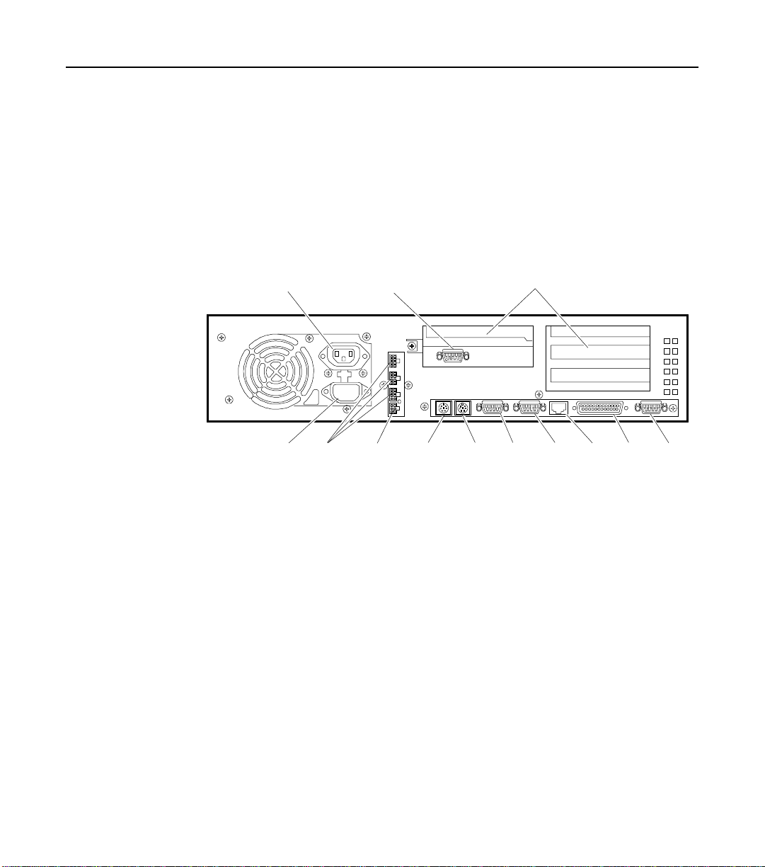
Connecting the NCR 5992 to the NCR 7452/3 Workstation
Migrating to the new 5992 Electronic Payment Terminal requires
minimal effo rt. Th e follo win g illustrat ions sh ow the st eps n e ed ed to
connect the 5992 to an NCR 7452/3workstation. Connector locations of
the workst at io n term in a ls m ay va ry slightly from m odel to mode l.
CRT AC Power Adapter Board Slots
Cable Conf ig ur ati o ns
The NCR 5992 Electr on ic P ayment Terminal may be installed with the
following cable co n fig urations or min or v a riat io ns of the followin g . See
your NCR representative for help with your particular configuration:
UPS Connector
AC Power Aux Power
Aux
Power
(Printer)
Keyboard
AT
Mouse RS-232
Port 1
AT/PCI (Shared)
Port2
AT
PCI
LAN
Parallel
Port
VGARS-232
13258
Page 25

Configuration 1
To RS-232 Port
on workstation
5945 RS-232 (9-Pin D shell) Cable
(5992-K010-V001)
5945 Power Cable Adapter
(5992-K021-V001)
Installation 3-9
5992 Signature Capture Terminal
(5992-K100-V001)
16649
Configurati on 1: 5992 connected to 7452/3 using 7452 Aux. Power.
5992-K100-V001 5992 Signature Capture Secure w/ Track 1, 2 MSR
5945-K010-V001 Cable: RS-232 (9-Pin D Shell)
5945-K021-V001 Cable: 7452/3 Power Adapter
Page 26
3-10 Installation
Configuration 2
To RS-232 Port
on workstation
5945 RS-232 Cable (9-Pin D Shell
(5945-K010-V001)
5992 Signature Capture Terminal
(5992-K100-V001)
5945 Power Supply
(5945-K020-V001)
16648
Configurati on 2: 5992 connected to 7452/3 using 120 VAC p ower.
5992-K100-V001 5992 Signature Capture Secure w/ Track 1, 2 MSR
5945-K010-V001 Cable: RS-232 (9-Pin D Shell)
5945-K020-V001 Power Supply: (120V, 60Hz US/Canada/Other)
Page 27

Installation 3-11
Configuration 3
RS-232 Serial Port Extender
(5945-K090-V100)
RS-232 Expander Cable
(5945-K091-V100)
To RS-232 Port
of Workstation
7452/3 Power Adapter Cable
(5945-K021-V100)
5992 Signature Capture Terminal
(5992-K100-V100)
16650
Configurati on 3: 5992 connected to 7452/3 using port exp ander an d Aux Power cable.
5992-K100-V001 5992 Signature Capture Secure w/ Track 1, 2 MSR
5945-K021-V001 Cable: 7452/3 Power Adapter
5945-K090-V001 RS-232 Serial Port Expander (2 port)
5945-K091-V001 RS-232 Expander Cable
Page 28

3-12 Installation
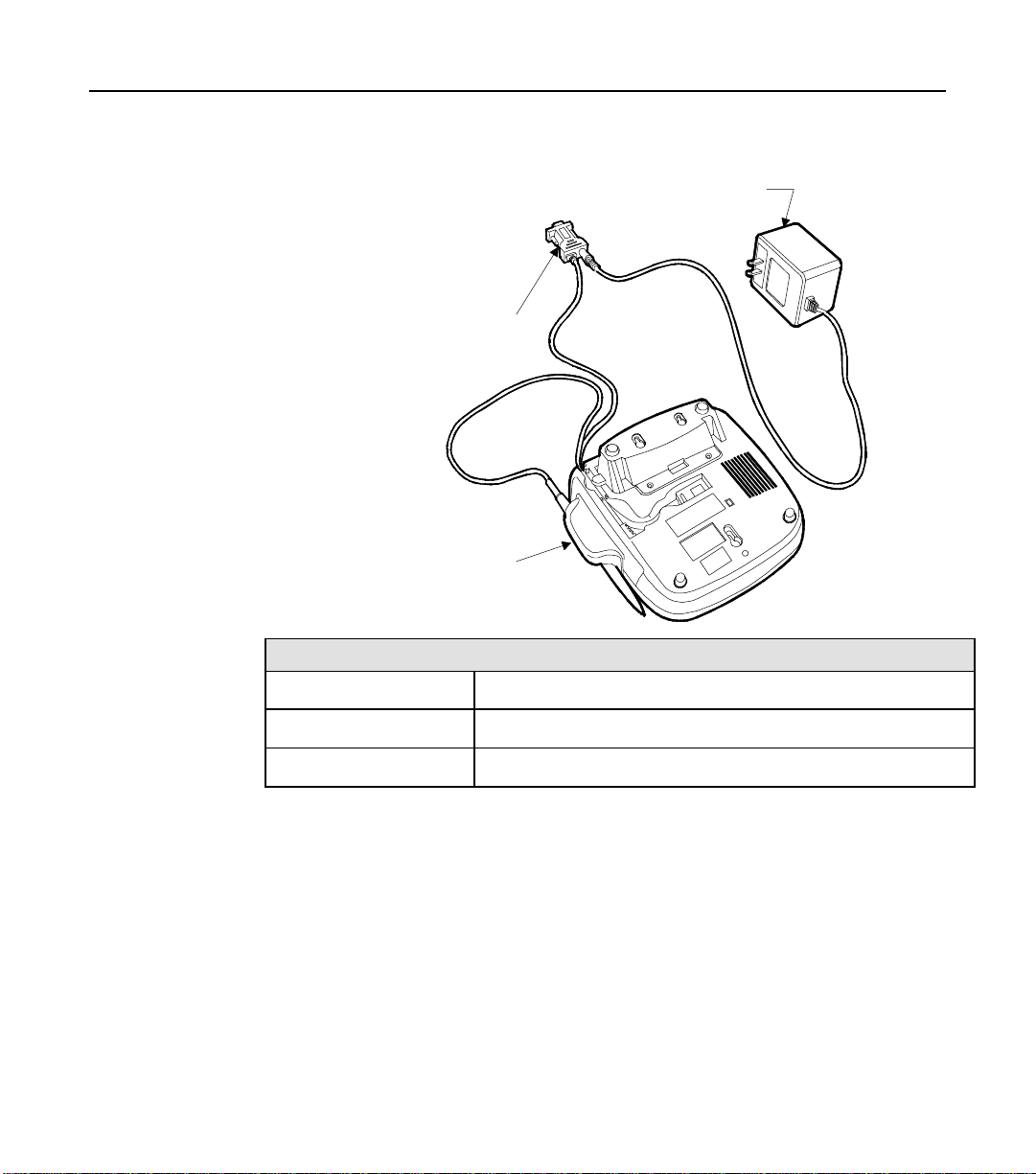
Conne cting the NCR 5992 to a PC
The following illu stration sh ows t h e steps nee d ed t o conn e ct the NCR
5992 to a PC.
PC Serial
Port
PC Serial
Port Connector
( DB 9 )
PC
5992 CAT
Pen Port
%992 CAT Cable
and Connector
( MiniDIN 9)
Power Supply
Connector
5992 CAT
Host Port
DC Power
Supply
16848
1. Turn Off Power to your PC.
2. Connect the NCR 5992 Cable and Stylus as previously described in
Connecting and Disconnecting the NCR 5992 Cable and Stylus
the
section.
Page 29

Installation 3-13
3. Plug the
NCR 5992 PC Serial Port Connector
(DB9) into a serial port
on the back of your PC.
4. Plug the
DC Power Supply
into a standard wall outle t.
Warning: Use only the DC Power Supply shipped with your unit.
Using any other power supply may damage the NCR 5992 and will
void the warranty.
5. Plug the Power Supply Connector into the Power Supply Jack on
the cable.
6. Once the NCR 5992 has power and the PC is signed on, it is ready
for use as determ ined by y our app lica t ion software.
Page 30

3-14 Installation
Page 31

Introduction
4-1
Chapter 4 Operational Modes
The NCR 5992 has two primary operational modes: Normal and
Supervisor/Diagnostic. The 5992 also has a Maintenance mode that
permits y ou t o mod ify it’s operations. In Normal mode, the 5992
performs signature capture and other functions for which it is
designed.
Supervis o r mod e allows a u tho riz e d p e rso nne l t o e xecu t e downlo a ds in
field installed 5992’s. The supervisor mode functions are menu driven
with featur es t h at allow a lo g ica l p rog ression through the in div idual
processes.
Normal Mode
The supervisor mode functions are:
• Modifying parameters.
• Downloading a program and parameters from a PC.
• Obtaining version information on the 5992.
• Re-initializing the 5992.
The diagn ostic mode allows auth oriz e d personal to isolate fa ilu res in
field installed 5992’s. The diagnostics are part of the operating system
and are not changed by applications. The diagnostics are menu driven
with featur es t h at allow a lo g ica l p rog ression through the in div idual
tests.
In normal mode, the 5992 is controlled by the application program
running in the host. Depending upon the application, any of the
following screens may be availa ble:
Page 32

4-2 Operational Modes
• Survey
• Promotional message
• Customer display
• Receipt o f ch a rge d isplay
• Form display
• Signature capture
The following illust rations show a typical relations h ip of 5992
functions to various phases o f a typica l a p plication p rog ram. In this
example, the only operator actions required are the normal keystrokes
on the host works t at io n keybo ard t o initia te a n d term in a te tra ns act io n
activities. The application has assigned the keyboard keys used to
accept or abort a signature. The only customer action required is to use
the stylus to sign the charge receipt display, form entry, or to respond
to surveys.
Page 33

Supervisor Mode
Startup Sequence
To access the 5992 supervisor mode:
1. The unit must be powered down.
2. Power up the unit and immediately place the stylus in the center of
the 5992 display screen. Hold the stylus in this position during the
power up as shown in the illu s t ra t ion below.
Operational Modes 4-3
3. The
Supervis or Men u | Diag nostics Menu
selection scree n will
display.
Note:
If Supervisor Menu or Diagno stics Menu is not se le cte d
within 10 seconds, the unit exits this screen and starts the 5992
application.
Center of Display
16840
Page 34

4-4 Operational Modes
4. Select
Supervisor Menu
Supervisor Menu
Prompts
Supervisor Menue
Keypad
with the stylus or your finger.
Enter Diagnostic
Password:
ABC DEF
QZ
1
GHI JKL MNO
4
PRS TUV
78
Cancel
2
3
56
WXY
9
Clear
0
YES
NO
E
N
T
E
R
5. An “Enter Password” prompt displays. Type in the password
“263” (“CME”), an d pr ess Enter. The first Supervis or Menu item
(CMDL) displays.
If an incorrect password is entered, a “Password Invalid” message
displays. Press any key to end the session and start the 5992
application. Then access the Supervisor Menu again.
16841
Note:
For diagnostics mode information, refer to Chapter 5, “5992
Diagnostics Specification
” in this User Manual.
Page 35

Operation
Navigating through the Menu Items
Supervisor Menu
Prompts
Supervisor Menu
Keypad
Enter Diagnostic
Password:
QZ
ABC DEF
23
1
GHI JKL MN O
56
4
PRS TUV
78
Cancel
0
Clear
Operational Modes 4-5
YES
NO
WXY
E
9
N
T
E
R
Yes Key
No Key
Cancel Key
Clear Key
Enter Key
NCR 5992 Supervisor Menu Key Features
KEY DESCRIPTION
Yes Used to scroll to th e p re vio us it em in th e menu list.
No Used to scroll to the next item in the menu lis t.
Enter Used to initia t e the cu rre n t ly disp la y e d menu ite m .
Cancel Ends an executing task and returns the Supervisor
Menu, or if pressed from a menu, ends the task and
returns the
Supervis or Menu Start Applic ati on
menu item.
Clear Used to end an executing task and return to the
Supervisor Menu.
16842
Page 36

4-6 Operational Modes
Menu Flow
The 5992 Supervisor Menu allows 9 individual functions to be
performed . Thes e opt ions display in th e followin g sequence:
1. CMDL. Used to download a program or parameters from a PC.
2. FILE SYSTEM. Used to view and modify file system read, write,
delete, co mp re ss, space report in g, and initialize sp a ce p a rame t e rs.
3. APP CONFIG. Used to change the size of the application
configur a tio n space.
4. ID BANNER. Displays the current version level of the 5992
firmware.
5. CHANGE PASSWORD. Changes the supervisor mode password.
6. SERIAL NUMBER. Displays the serial number of the 5992 unit.
7. HARDWARE CONFIG. Used to change the size of the hardware
configuration space. This function is currently not available.
8. POWER DOWN. Powers down the 5992 unit.
9. START APP. Starts the 5992 application.
Supervisor Menu Items
CMDL
CMDL is the first menu item that appears when the Supervisor Menu
displays.
CMDL is used for downloading a program or parameters from a PC,
using th e cable p ro v ide d with the IBM EFT Application D e v elo p e r ’s
Kit.
For detailed in fo rm a t ion on down loa din g a prog ram o r parame t ers,
refer to Chapter 2, “
Guide
.
Note:
Supervisor Menu.
Press the Cancel key to abort the download and return to the
Download Program Software
”, in the
5992 Developer’s
Page 37

Operational Modes 4-7
File System
The File Syst em opt ions a llow for mod ify in g parameters an d file
system maintenance functions. The File Sys Menu contains the
following m enu ite ms :
Init Space
File Sys Me nu
Read
. Select the
Read, Write, Delete, Compress, Space Report,
File Sys
menu item from the Supervisor Menu.
and
Note:
A listing of the sta n da rd parame t er set is loca te d in you r
Developer’s Guide
. Each parameter contains the corresponding
5992
applicatio n n um ber , file n umber, record number, and class.
Read
The read item allows for vie win g a parame t er.
1. Select the
Read
item on the File Sys M enu . E n t e r the following
information (as prompted) to read a parameter item.
Enter App #
_
2. The first prompt request s th e applicat ion n umbe r. A ll parame te rs
for the 5992 application use application number “1”. Type in “1”,
and press Enter. The next prompt displays:
Enter File#
_
3. This prompt requests the file number. Th e file nu mber refers to the
individual parameter. Type the file number, and press Enter. The
next prompt displays:
Note:
Refer to your
5992 Developer’s Guide
for the corresponding file
number.
Page 38

4-8 Operational Modes
Enter Record #
_
4. This prompt requests the record number. The record number is
used to refer to an individual parameter in a group of parameters.
Type the record number, and press Enter. The next prompt
displays:
Note:
Refer to your
5992 Developer’s Guide
for the corresponding
record number.
Enter Class #
_
5. This prompt requests the class number. The parameter class is
either “public” or “private”. Type one of the following class
numbers, and press Enter.
• “0” for private class. Private parameters are only used by the
specified a p plication.
• “1” for public class. P ublic parameters ca n be use d by a ll of the
applications loaded on the 5992 unit. Parameters such as the
terminal serial number, and the program and parameter
version lev e ls a re cons id er ed public paramet ers.
Note:
Refer to your
5992 Developer’s Guide
for the appropriate class.
6. If a valid record is entered, the information displays. If the record
was not found, an error message displays. Press any key to return
to the File Sys Menu. Then press the Cancel key to return to the
Supervisor Menu.
Write
The write item allows fo r modifica tio n s o r e n t ries t o a paramet er.
1. Select the W rit e item on th e File Sys Menu. Enter the followin g
information (as prompted) to modify or write a parame t er item.
Page 39

Operational Modes 4-9
Enter App #
_
2. The first prompt request s th e applicat ion n umbe r. A ll parame te rs
for the 5992 application use application number “1”. Type in “1”,
and press Enter. The next prompt displays:
Enter File#
_
3. This prompt requests the file number. Th e file nu mber refers to the
individual parameter. Type the file number, and press Enter. The
next prompt displays:
Note:
Refer to your
5992 Developer’s Guide
for the corresponding file
number.
Enter Record #
_
4. This prompt requests the record number. The record number is
used to refer to an individual parameter in a group of parameters.
Type the record number, and press Enter. The next prompt
displays:
Note:
Refer to your
5992 Developer’s Guide
for the corresponding
record number.
Enter Class #
_
5. This prompt requests the class number. The parameter class is
either “public” or “private”. Type one of the following class
numbers, and press Enter.
• “0” for private class. Private parameters are only used by the
specified a p plication.
• “1” for public class. P ublic parameters ca n be use d by a ll of the
applications loaded on the 5992 unit. Parameters such as the
terminal serial number, and the program and parameter
version lev e ls a re cons id er ed public paramet ers.
Note:
Refer to your
5992 Developer’s Guide
for the corresponding class.
Page 40

4-10 Operational Modes
Enter Data:
_
6. This prompt requests the data that should be contained at the
selected lo cat io n . For example, if this lo ca tio n wa s intended to
contain the baud rate, enter the baud (e.g., 9600), and press Enter.
Then, when s e tt ing th e bau d v a riable in the application, th is
location would need to be referenced.
Note:
File Writ te n.
Press a Key...
The Clear key is used to back up one space in case of error.
7. The parameter file is written. Press any key to return to the File Sys
Menu. Then press the Cancel key to return to the Supervisor Menu.
Delete
The delete it em allo ws fo r delet in g a param e t er. Us ing the 5 992
keypad, you can delete a parameter.
Warning:
Deleting a parameter tha t the application r e quire s will
cause the application to sto p work ing.
1. Select the
Delete
item on the File Sys Menu. En te r the following
information (a s p rompted) to delete a param et e r item.
Enter App #
_
2. The first prompt request s th e applicat ion n umbe r. A ll parame te rs
for the 5992 application use application number “1”. Type in “1”,
and press Enter. The next prompt displays:
Enter File#
_
3. This prompt requests the file number. Th e file nu mber refers to the
individual parameter. Type the file number, and press Enter. The
next prompt displays:
Note:
Refer to your
5992 Developer’s Guide
for the corresponding file
number.
Page 41

Operational Modes 4-11
Enter Record #
_
4. This prompt requests the record number. The record number is
used to refer to an individual parameter in a group of parameters.
Type the record number, and press Enter. The next prompt
displays:
Note:
Refer to your
5992 Developer’s Guide
for the corresponding
record number.
Enter Class #
_
5. This prompt requests the class number. The parameter class is
either “public” or “private”. Type one of the following class
numbers, and press Enter.
• “0” for private class. Private parameters are only used by the
specified a p plication.
• “1” for public class. P ublic parameters ca n be use d by a ll of the
applications loaded on the 5992 unit. Parameters such as the
terminal serial number, and the program and parameter version
levels are cons id er ed public paramet ers .
Note:
Refer to your
5992 Developer’s Guide
for the corresponding class.
6. If a valid record is entered, the “Parameter Deleted, Press a key”
promp t displays. P re ss a ny key to retur n t o the File Sys Menu.
Then press the Cancel key to return to the Supervisor Menu.
Compress
The compress item purges deleted records giving you additional
configur a tio n space.
1. Select the
Compress
item on the File Sys Menu . Enter the following
information (as prompted) to compress .
Enter Class #
_
Page 42

4-12 Operational Modes
2. This prompt requests the class number. The parameter class is
either “public” or “private”. Type one of the following class
numbers, and press Enter.
• “0” for private class. Private parameters are only used by the
specified a p plication.
• “1” for public class. P ublic parameters ca n be use d by a ll of the
applications loaded on the 5992 unit. Parameters such as the
terminal serial number, and the program and parameter
version lev e ls a re cons id er ed public paramet ers.
3. The compress is executed. When completed, the “Compress OK,
Press a key” prompt displays. Press any key to return to the File
Sys Menu. Then press the Cancel key to return to the Supervisor
Menu.
Space Report
The space report ite m disp la ys informatio n on configuration spa ce.
1. Select the
Space Report
item on the File Sys M enu. The fo llowin g is
an example of the information that displays.
Enter Class #
_
2. This prompt requests the class number. The parameter class is
either “public” or “private”. Type one of the following class
numbers, and press Enter.
• “0” for private class. Private parameters are only used by the
specified a p plication.
• “1” for public class. P ublic parameters ca n be use d by a ll of the
applications loaded on the 5992 unit. Parameters such as the
terminal serial number, and the program and parameter
version lev e ls a re cons id er ed public paramet ers.
Page 43

Operational Modes 4-13
L: 4E200 F:9 76 4
Press a Key. . .
3. Two separate items display:
• L: Displays the lengt h of t he storage spa ce .
• F: Displays the number of free bytes available.
4. Press any key to return to the File Sys Menu. Then press the Cancel
key to return to the Supervisor Menu.
Init Space
The initialize space item is use d to clea r the con figuration spa ce or
change the size of the configuration space.
Warning:
Using this command will rem ove any prog ra m or
parameters currently loaded on the 5992.
Note:
Refer to Chapter 2, “
5992 Developer’s Guide
Programming Considerat io ns,
” in your
for detailed info rm a t ion on the systems file
space.
To change the size of the configuration space, press Enter.
1. Select the
Init Space
item from the File Sys Menu. Th e Init Spa ce
Menu displays.
Init Spac e Me nu
Config Sp ac e
2. Press Enter to select the
Enter Cfg Size
_
Config Space
item.
3. This parame t er is us e d to specify t h e s ize of th e con fig uration
space. This p a rame te r is set to z ero whe n th e un it is new. For the
IBM EFT applica t io n , this valu e sho u ld be s e t to approximate ly
260KBytes. Type the configuration size, and press Enter.
NCR
Page 44

4-14 Operational Modes
Enter Cfg Size
Complete
4. This messa ge displays wh en t he space configu r a tio n is co mpleted.
Press any key to return to the File Sys Menu. Then press the Cancel
key to return to the Supervisor Menu.
Application Configuration
The application configu ra tio n opt ion s a llo w for re con figuring spa ce for
a specific application. The App Config Menu con t a in s t h e
and
init sp a ce
functions. Select the
App Config
menu item from the
space report
Supervisor Menu.
App Config Menu
Space Report
Space Report
The space report it e m disp la y s in formation on the application
configur a tio n space.
1. Select the
Space Report
item on the App Config Menu. The
following is a n ex ample of the informat io n tha t d isp la ys.
L: EA60 S: D7F8
Press a Key. . .
2. Two items dis p lay :
• L: Displays the lengt h of t he storage spa ce .
• S: Displays the addres s wh e re s t o rag e sp a ce is loca t e d in physical
memory.
3. Press any key to return to the App Config Menu. Then press the
Cancel key to return to the Supervisor Menu.
Init Space
The initialize space item is use d to clea r the con figuration spa ce or
change th e size of th e conf ig u r a t ion spa ce o f the sp e cifie d a pplication .
Warning:
Using this command will rem ove any prog ra m or
parameters currently loaded on the 5992.
Page 45

Operational Modes 4-15
Note:
Refer to Chapter 2, “
5992 Developer’s Guide
Programming Considerations
” in your
for detailed info rm a t ion on the systems file
NCR
space.
App Config Menu
Init Spac e
1. Select the Init Space item from the App Config Menu.
Enter Apps Size
_
2. This parame t er is us e d to specify t h e s ize of th e con fig uration
space. This parameter is set to 128KBytes when the unit is new. For
the IBM EF T applica t io n , this value should not hav e t o cha ng e .
Type the application configuration size, and press Enter.
Enter Apps Size
Complete
3. This messa ge displays wh en t he space configu r a tio n is co mpleted.
Press any key to return to the App Config Menu. Then press the
Cancel key to return to the Supervisor Menu.
ID Banner
The ID banner option displays the current version level of the 5992
firmware. Select the
ID Banner
item on the Superviso r Me n u an d press
Enter. The version in fo rm a t ion disp la y s. P r ess any key to return to th e
Supervisor Menu.
Change Password
The change password option allows the password to access Supervisor
Mode to be changed. Select the
Menu and press Enter.
Note:
Ch angi ng the Supervisor Mo de password does not af fect the
Diagno st ics Mode password .
Change Pas s wor d
item on the Supervisor
Page 46

4-16 Operational Modes
Supervi so r Me nu
Change Pa ss wo rd
1. Select
Change P as s wor d
from the Supervisor Menu, by pressing
Enter.
Enter New Password
_
2. Type in the new password, and press Enter.
Note:
The default password is “263” (CME). The new password may
not be larger than 32K.
Verify Ne w Pa ss word
_
3. Type in the new password again (to confirm), and press Enter. If
the same pass wo rd is ent ere d, t h e new password will be written to
memory and the following message displays.
Note:
If the verify password entered is not the same, a “Denied PW
Chg” message displa ys. Press Enter to return to the Supervisor Menu.
Changed PW
Press Enter
4. This mess a g e displays when t he n e w password has been writ t e n
into memory. Press the Enter key to return to the Supervisor Menu.
Serial Number
The serial number option displays the serial number of the 5992 unit.
Select the
Serial Number
item on the Supervisor Menu and press Enter.
The serial number of the unit displays. Press any key to return to the
Supervisor Menu.
Hardware Configuration
The hardware configuration option is used to change the size of the
hardware configuration space. This option is currently not available.
Page 47

Operational Modes 4-17
Power Down
The power down option is used to power down the 5992 unit. Select
Power Down
the
5992 will power down and be in an offline state.
item on the Supervisor Menu and press Enter. The
Start Application
The start application option is used to start the 5992 application. Select
Start App
the
applicatio n p r ogra m will in it ializ e a n d start. If an applica t ion program
is not loaded for the unit , a n “Inv a lid A pp 1” message displays.
item on the Supervisor Me nu and pre ss Enter. T he
Page 48

4-18 Operational Modes
Maintenance Mode
When power is applied to the 5992, it begins Power-up diagnostics. If
the status of all tests is “Passed,” a tone sounds. To enter Maintenance
Mode, immediately touch the stylus to the NCR logo at the upper right
corner of the screen.
Note: If you wait too long, the 5992 will enter normal mode and you
will have to p owe r off an d st ar t over.
The Mainte n a n ce M od e disp lays permit you to sele ct options that
modify the operation of the 5992. Instructions are displayed, and
options are selected with the touch of the stylus.
The main menu displays the firmware and software identification
numbers plus the following choices:
• SETUP procedures to establish operating parameters
• DIAGNOSTICS to verify operation
• RUN to termina te Maint en ance Mod e and in itia t e No rmal M o de of
operation
• LOAD APPLICATION to make the 5992 ready to receive a
download of the operating system
The RUN option of the main menu terminates Maintenance Mode and
initiates No rm a l Mode op er at io n.
Performi ng a Set u p
Enter SETUP from the Maintenance Mode menu by touching the stylus
to the SETUP sele ctio n . SETU P let s y ou do any of the follo win g :
• Calibrate the digitizer
• Adjust the screen contrast
• Set the EIA-485 link address
• Set the EIA-232 mode (manual or automatic)
• Doo dle ( tests the stylu s and d i git i zer)
Page 49

Operational Modes 4-19
Digitizer Calibratio n
Calibration of the digitizer is done at the factory and should never
require readjustment. If you experience a digitizer tracking problem,
contact an NCR service representative prior to attempting any
adjustments.
Screen Contrast Adjustmen t
When you enter this mode, the screen displays a light and dark
checkerboard pattern. To lighten the screen, drag the stylus from the
left to the right. To darken the screen, drag the stylus from the right to
the left.
Note: It is possible to adjust the screen contrast so that the menu
options are not visible. It is then very difficult to select the option to
adjust it properly. If this occurs, momentarily unplug the power
module from th e electr ical power outlet and the n recon n e ct it t o initia te
the self-test diagnostics. Then, hold the stylus tip on the screen for four
seconds to establish a default contrast value.
EIA-485 Link Address
If your 5992 utilizes an EIA-485 interface with an IBM-468x host, you
must set the link address at installation. If your 5992 utilizes and EIA485 2-wire multidrop link interface, you must set the link at
installation.
EIA-232
If not manually set, the RS-232 communication baud rate will
automatically be set via the first communications message following
the unit power cycle. The highest rate that can be detected in autobaud
mode is 19.2Kbps. If 38.4Kbps is required, it must be set by selecting
the 38.4Kbps option from the menu.
Page 50

4-20 Operational Modes
Performi ng Di a gno sti cs
The 5992 runs ROM-based Power-up diagnostics automatically, and
user-selectable diagnostics (also ROM-based) on demand.
Extende d d iagnostics an d diagn ostics logs an d tallie s may be run from
the host.
User-selectable diagnostics permit the user to:
• Display video screens
• Test the Backlight
• Test ping-pong communications
• Read or clear the 5992 tallies
• Test MSR
To perform user-selectable diagnostics:
1. Touch the NCR logo with the stylus immediately after Power-up
diagnostics comp le t e.
2. Touch the stylus to DIAGNOSTICS on the Maintenance Mode
menu, and follow the prompts.
What are tallies?
Tallies record th e number of sends, receiv es, power cycles, reads,
failures, etc., related to the 5992’s internal op e r a tio ns , co mmunicatio n s,
MSR, and operating system.
What is the ping-pong test?
The ping-pong test must be initiated from the host. It verfies the
operation of the communica t ion s interface , the interface cable, and the
5992, by returning all messages received from the host.
Page 51

Operational Modes 4-21
Loading the Operating System
The load option is entered from the Maintenance Mode menu by
touching the stylus to the LOAD OPERATING SYSTEM selection. The
load option es ta blishes condit ions that permit the 59 92 to receiv e an
operating system download from the host. An operating system load
should only be req u ire d to inst a ll a new ope ra ting system vers ion
supplied by NCR.
It is not necessary to enter Maintenance Mode to download the
operating system. This can be done at any time in Normal Mode from
the host. Th e down loa d also can be initiated at th e end of Powe r-up
diagnostics, if a test fa ils.
After reloadin g the oper at in g sys t em, an application lo ad is re quire d.
This als o mus t be in it ia te d from t h e host . If t h e ap plicat io n is not
loaded, the 5992 displays “APPLICATION NOT PRESENT, LOAD
APPLICATION.”
The 5992 Utility Diskette contains the Operating System. To load the
Operating System, you need a 386 or higher processor with a 3.5” disk
drive. You also can use the host terminal if it has a 3.5” disk drive.
Perform the following steps.
1. With the PC on, go to the DOS prompt (
2. Type
3. Type
4. Identify the most cu rre n t Ope ra t ing Syst e m an d App licat io n files –
5. Run the Utility pro g ram by typ in g
Note: The 5992_ut.exe utility is the same utility used for the 5991 as
only the filen a m e was ch a ng ed . A ll me n u te x t st ill re fe rs to the 5991
only, but applies to the 5992 as we ll.
6. Select the communication type and port as prompted.
cd a:
dir
OS*.out and APP*.out.
Enter.
and press Enter to change to the 3.5” disk drive.
and press Enter to display the disk directory.
5992_ut.exe
C:\
).
and pressing
Page 52

4-22 Operational Modes
7. Select the Baud Rate from the menu (The 5992 can be manually set
to 38.4Kbps , h o wev e r the diag nostics and utilities suppo rts up to
19.2Kbps).
8. The Utilities Menu is now displa yed.
• Select 09 – Reset unit
Response:
00 05 00 ef ea
Press Enter to send the reset command again (The response
code of ef means this is the first command since power up)
OR
Response:
This is the correct response,
00 05 09 00 0C
ef
changes to
00
• Select D2 – Load Operating System
Type filename (OS*.out)
Type 0 to stream data (fastest)
Note: The download will take several m inu te s. The date being
transferre d will be displayed on the PC (or host t e rmin al) a n d a
counter on the 5992 will indicate how many blocks of data have benn
downloaded. Typically, this is at least 700 block s . Once the OS
download is complete, the 5992 will reset. At this point the 5992 will
not be operat ional until an applicat io n is downloade d . A ft er res e t, the
5992 will display
NCR EFT, Wait for On line
. This indicate s the
5992 is waiting for an application download.
9. Press Q to return to main menu.
10. Select D2 – Load Applications.
11. Enter filename. (APP*.out)
12. Enter 0 to stream data (fastest).
13. Press Q to return to main menu.
14. Press 00 to exit the 5992 Utility.
15. If the Operat ing Syste m Pr ogram Memory passes in it ia l
diagnos t ics, the unit goes int o the norm a l run m od e.
End of Procedure.
Page 53

Chapter 5 Troubleshooting
Introduction
In the event you r NCR 5 9 92 is no t working properly, you sh ould first
consult the following troubleshooting tables. Find the problem you are
experiencing in the
actions in the
Note: If all solu tio ns h av e been t r ied an d you are st ill experiencin g
problems, contact
be shipp ed ba ck for re pair.
Simple Troubleshoot ing Gui de
PROBLEM SOLUTION
The Card
Reader does
not seem to
work
properly.
Make sure that the magnetic stripe on the card is facing the NCR 5992
graphica l display screen when s liding the card throug h th e reade r.
Swipe the card at a faster or slower
Swipe the card in the re v erse dire ctio n (i.e., if swiping the ca rd from righ t
to left, try swiping from left to righ t ).
Solution
Problem
NCR Help Desk
column, pe rf or m (in se q uence) each o f th e
column.
to make arrangements for the unit to
steady
speed.
5-1
The NCR
5992 is not
working.
Inspect the magnetic stripe on the card, making sure it is not scratched or
badly worn.
If you have another working NCR 5992 unit, try reading the card on that
unit to determine if the problem is with the unit or with the card.
Make sure the NCR 5992 Connector (MiniDIN 9) is fully inserted into the
back of the unit.
Unplug the unit and plu g it ba ck in.
If you have ano t h e r working NCR 5992 unit, swap the units to de t e rmin e
if the problem is with the unit, cable, register, or power supply.
Page 54

5-2 Chapter 5 Troubleshooti ng
S
Detail ed Pro blem Tr o ubl es h ooti ng
For diagnostics instructions, refer to Chapter 6 of this guide.
Indication Possible Cause Acti on
Display is dark
(backlight is off).
Display is dark but
readable.
Automatic display
blanking activated
No power
Power supply/ adapter
failure
5992 awaiting host
commands
Improper cable
connections
Interface cable failure
5992 failure Replace the 5992.
Power supply/ adapter
failure
5992 failure Try another 5992.
end Host Command.
Check power
connections.
Try a new power
supply.
Send host co mmand.
Check all cable
connections.
Replace or repair the
damage d ca b l e s.
Contact the NCR
Support Center.
Try a new power
supply.
Contact the NCR
Support Center.
Display is faint. Screen contrast is set
improperly
5992 failure Try another 5992.
Display is blank Improper cable
connections
Set screen contrast.
Contact the NCR
Support Center.
Check all internal
cable con nections.
Page 55

Chapter 5 Troubleshoot i ng 5-3
G
2
C
Indication Action
Screen contrast
Set screen contrast.
set improperly
5992 failure Try another 5992.
Contact the NCR
lobal Support Center.
5992 failed OS
program memory
test on power-up.
Improper loading
by host.
1) Reload the 5992
operating system an d
application.
) Power cycle the 5992
and make sure it resets
automatically after
loading.
3) Make sure the OS
program memory test
passes.
4) Load video screens
5992 failure Try another 5992.
Contact the NCR
Center.
Stylus does not
work.
Loose cab l e connecti o ns. Check styl us cable
connections.
Bad stylus connection. Check stylus
connection.
Improper calibration.
alibrate the digi tizer.
Stylus not enab le d. Run diagnostics.
Stylus failure. Replace stylus.
Defective 5992 unit. Check stylus on
another 5992 unit.
Interface cable failure. Replace or repair the
cable.
5992 failure. Try another 5992.
Contact the NCR
Support Center.
Page 56

5-4 Chapter 5 Troubleshooti ng
D
5
Indication Action
isplay doesn't track
the stylus.
Improper calibration. Perform
stylus/digitizer test.
Stylus failure. Replace stylus.
5992 failure. Try another 5992.
Contact the NCR
Support Center.
MSR did not read
card.
Card not run through
properly.
Run card through w i t h
the magnetic stripe
down and f aci ng the
front of the 5992.
Bad card . Try another card .
5992 does
not respo nd to host
commands.
Wrong MSR
configuration.
Perform MSR test in
992 diagnostics mode.
MSR not enabled. Send "Activate MSR"
command from host
5992 failure. Try another 5992.
Contact the NCR
Support Center.
Improper cable
connections.
Wrong communication
speed setting.
Check all cable
connections.
Initiate power-up
diagnosti cs an d send
two messages from the
host.
Interface cable failure. Replace or repair the
cable.
5992 failure. Try another 5992.
Contact the NCR
Support Center.
Page 57

Introduction
6-1
Chapter 6: Diagnostics Specification
This chapter describes the diagnostic test procedures for the NCR 5992,
K100 and K150 Signature Capture Terminals. The purpose of the
diagnostics is to isolate failures in field installed 5992’s. The diagnostics
are part of the operating system and are uniform across all
applicatio n s. The diagnost ics are menu driven wit h feat u r e s th at allo w
a logical progression throug h th e indiv idu a l t est s.
Startup Sequence
The diagnostics can be accessed either at power-up or from any screen.
1a. To start diagnostics at power-up, the unit must be powered down.
Power up the unit and allow 20 to 30 seconds for the unit to ‘self
test’. Place the stylus in the center of the 5992 display screen. Hold
the stylus in this position during the power up as shown in the
illustration be low. The
selection s cre e n will dis p la y.
Supervisor Menu | Diagnostics Menu
Center of Display
16840
Page 58

6-2 Chapter 6: Diagnostics Spec if ication
Note:
If Supervisor Menu or Diagno stics Menu is not se le cte d
within 10 seconds after ‘self test’, the unit exits this screen and goes
into the digitizer calibration screen.
1b. To start diagnostics from any screen, touch each corner of the
screen in a counter clockwise motion starting with the upper left
hand corner using the stylus or your finger. You must finish by
pressing the same upper left hand corner of the screen where you
started. There are a total of 5 screen touches. The
| Diagnosti c s Menu
selection s cree n will display.
Supervi s or Menu
Touch the scr ee n five times in a counter clock wise direction , in ea ch
corner starting and finishing with a touch in the upper left hand corner
of the screen. The
Supervis or Men u | Diag nostics Menu
selection screen
will display .
2. Select
Diagnos tics Menu
with the 5992 stylus or your finger.
Page 59

Chapter 6: Diagnostics Specification 6-3
Enter Diagnostic
Diagnostics Menu
Prompts
Diagnostic Menu
Keypad
Password:
QZ
ABC DEF
2
1
GHI JKL MNO
56
4
PRS TUV
78
Cancel
0
WXY
Clear
YES
3
NO
E
9
N
T
E
R
16844
3. An “Enter Diagnost ics Pas sword” prompt displays. Type in the
password “3424” (“DIAG”), and press Enter. The first diagnostics
test menu item (KEYPAD) displays. If an incorrect password is
entered, a “Password Invalid” messa g e displays. P r e ss a n y ke y t o
end the session and start the 5992 application. Then access
diagnostics mode again.
Note:
If the applicat io n p r ogram is not executin g (e .g., the screen will
either display “Waiting for Online” or will be downloadin g a program
and/or parameters), the diagnostic screen is not accessible.
For supervisor mode information, refer to Chapter 4, “
Supervisor Mode
” in this User Manu al.
Using t h e
Page 60

6-4 Chapter 6: Diagnostics Spec if ication
Operation
Navigating through the Menu Items
Diagnostics Menu
Prompts
Diagnostics Menu
Keypad
Enter Diagnostic
Password:
QZ
ABC DEF
2
1
GHI JKL MNO
56
4
PRS TUV WXY
78
Cancel
0
Clear
YES
3
NO
E
9
N
T
E
R
Yes Key
No Key
Cancel Key
Clear Key
Enter Key
NCR 5992 Diagnostics Menu Key Features
KEY DESCRIPTION
Yes Used to scroll to the previous it em in th e menu list.
No Used to scroll to th e nex t item in the menu lis t.
Enter U sed to initiate the currently displa y e d menu ite m .
Cancel Ends an executing diagnostics test and returns the
diagnostics menu, or ends the diagnostics if pressed
from a menu and restarts the NCR 5992 application.
Clear Used to end an executing diagnostics test and return to
the diagnostics menu.
16845
Page 61

Chapter 6: Diagnostics Specification 6-5
Menu Flow
The 5992 Diagnostics Menu allows for 16 individual tests to be
performe d. Th es e t es t s display in the followin g sequence:
1. KEYPAD TEST: Verifies that each key on the keypad is
functioning properly.
2. DISPLAY TEST: Tests the 5992 display screen checking that all
displayable characters can display and that each pixel is
functioning properly.
3. MSR TEST: The MSR diagnostics test the 5992 Magnetic Stripe
Reader, checking that track 1, track 2, and track 3 (if installed), is
reading properly.
4. IBM 46xx TEST: Tests the 5992 communication parameters using
the RS485 IBM 4680 Feature C protocol.
5. HOST RS232 TEST: Sets the 5992 Baud Rate, Parity, Data Bits, and
tests the host communication port.
6. AUX1A RS232 TEST: Sets the 5992 Baud Rate, Parity, Data Bits,
and tests the AUX1A communication port.
7. AUX1B RS232 TEST: Sets the 5992 Baud Rate, Parity, Data Bits,
and tests the AUX1B communication port.
8. SRAM TEST: Runs a read and write test on the RAM chip.
9. ENCRYPTION TEST: Tests the Security Module encryption
(Maste r Sess io n or DUKP T) wit h an in t e rnally d e fin e d a ccount
number and PIN.
10. OS VERSION: Displays the current software OS version number.
11. LIBRARY VERSION: Displays the current software library
version number.
12. SECURITY VERSION: Displays the current software security
version number.
13. CALIBRATE: Recalibrates the digitizer by making the digitizer’s
coordinates match the LCD’s.
Page 62

6-6 Chapter 6: Diagnostics Spec if ication
14. STYLUS TEST: Tests the stylus by signing on a blank screen and
checking both the digitizer and the stylus.
15. LCD CONTRAST: Adjusts the LCD contrast (lighter or darker) on
the 5992 display screen.
16. SHOW TOUCHES: Displays a blank screen and turns on the pixel
where touched by the stylus or finger. This test is used to test the
digitizer calibration.
Keypa d Test
The keypad diagnostics test that each key on the 5992 keypad is
functionin g properly. S e lect the KEYPAD TEST from the Diagnostics
Menu:
DIAGNOSTICS
Keypad Te st
Each key on the keypad must be pressed in the defined sequence and
within 30 seconds. Begin test by pressing the keys starting at the top
left corner of the keypa d (1). Mov e left to right and downward until all
keys have been pressed. The Enter key should be pre ssed last (aft e r the
Clear key).
If all key presses are detected properly, the following message
displays:
Test Pass ed
Press any key . . .
If the exact key sequence is not pressed, or not pressed within the
allotted 3 0 seconds, t he fo llowing messa ge displays:
Test Fail ed
Press any key . . .
Pressing any key on the keypad returns the Keypad Test Menu. The
keypad Yes and No keys are used to navigate through the available
diagnostic test menus, or press Cancel to exit the session and start the
5992 application.
Page 63

Chapter 6: Diagnostics Specification 6-7
Display Test
The display diagnostics test the 5992 display screen checking that each
pixel is fun ct io n ing properly . S ele ct t h e DISPLAY TEST from the
Diagno st ics Men u:
DISPLAY TEST
Press any key . . .
Press any key to continue. The pixels are tested to determine if any are
not working, or ar e stuck on. The following s e que n ce is us e d:
1. All pixels on (wh it e scre e n dis plays)
2. Every other pixel off (lined screen displays)
3. All pixels off (blank purple scre en dis plays)
4. Every other pixel on (lined screen displays)
If the test passed, the Diagnostics Display Test screen displays again. If
the test fa iled , the following mes sage displays :
Test Fail ed
Press any key . . .
MSR Test
Press any key to return to the Display Test screen. The keypad Yes and
No keys are used to navigate through the available diagnostic test
menus, or press Cancel to exit the session and start the 5992
application.
The MSR diagnostics test the 5992 Magnetic Stripe Reader. A valid
magnetic stripe card, preferably one with both track 1 and 2, must be
available to perform this test. Most any Visa or AMEX card should
work. Select the MSR TEST from the Diagnostics Menu.
MSR TEST
Swipe card...
Swipe a valid MSR card wit h the magnetic stripe facing the disp la y
screen. You can swipe in either direction. After the first card is slid, the
display changes to:
T1= 001 T2= 001
T3= NTrk TOT=001
Page 64

6-8 Chapter 6: Diagnostics Spec if ication
T1 through T3 (track 1, 2 and 3) accumulates and displays the number
of times a ca rd was successfully swiped and re a d corre ctly for that
track. TOT keeps a running tally of how many card swipes have been
performed. If an error is detected for a track, the error code displays.
The following table shows the error codes and their associated
description.
ERROR CODE DESCRIPTION
LRCE Longitudinal Redundancy Check Error
NoES No End Sentinel character
NoFS No F ield Sep arator
NoSS No Start Sentinel character
NTrk No Card Track Installed
ParE Parity Error
PrsE Parse Error
???? Unknown ca rd ty p e for t r ack
The following screen shows an example of 5 good reads for track 1, a
parse error on track 2 data, track 3 not installed, and a total of 5 card
swipes.
T1= 005 T2= PrsE
T3= NTrk TOT=005
The test ends when the Cancel key is pressed and the MSR Test screen
is displayed. The keypad Yes and No keys are used to navigat e
through the available diagnostic test menus, or press Cancel to exit the
session and start the 5992 application.
Page 65

Chapter 6: Diagnostics Specification 6-9
IBM 46xx Test
The IBM 468x, 469x diagnostics test the 5992 communication using the
RS485 IBM 4680 Feature C protocol. Select the IBM 46xx TEST from
the Diagn ostic s Me nu:
IBM 46xx TEST
2A23 <0x68>
The second line displays the first slot and port number option that can
be teste d.
The keypad Yes and No keys are used to scroll up and down through
the 4 available slot and port number options. These 4 options are:
1. 2A23 <0x68>. Selects slot 2A, port 23. This compares to the Feature
C address 0x68 (104).
2. 2A25<0x64>. Selects slot 2A, port 25. This compares to the Feature
C address 0x64 (100).
3. 2B23<0x69>. Selects slot 2B, port 23. This compares to the Feature C
address 0x69 (105).
4. 2B25<0x65>. Selects slot 2B, port 25. This compares to the Feature C
address 0x65 (101).
To test the Feature C port, select the port by pressing the Enter key
when the appropriate slot and port option displays. The following
information d isp la y s:
Testing 2A23
Poll Coun t 000 0
The first line dis p lays t h e slot and port option selected.
The Poll Coun t on line t wo d isp la ys the number of Polls (d iv ide d by
40) that have been re ce ive d a t th is port. P olling always s ta rts from ze ro.
If the selected Feature C port is active on the IBM 46xx, the number of
polls increment about once every second. This indicates that
communications with the IBM 46xx register are being conducted.
Page 66

6-10 Chapter 6: Diagnostics Specification
Pressing the Cancel key during this test returns the IBM 46xx Test
screen. The keypad Yes and No keys are used to navigate through the
available diagnostic test menus, or press Cancel to exit the session and
restart the 5992 application.
Host RS232 Test
The host RS232 diagnostics sets the 5992 baud rate, parity, data bits,
and tests t h e comm unication port . Se le ct HOST RS232 TEST from the
Diagnostics Menu. The following communications selection screen
displays:
Host 19200,N,8
Test
The default parameters display on the first line. The keypad Yes and
No keys are used to scroll up and down through the selections. The
available s ele ct ions are:
Test Allows a port tes t to be pe rformed for the para meters
selected.
Baud Rate Allows a differ ent Baud Rate to be sele cted.
Parity Allows a diff er en t Parity to be selected.
Data Bits Allows a differ ent Data Bit to be selec ted.
The Enter key is used t o choo se the display ed s e lect io n scre e n for
parameter entry.
Test Selection
Select
Test 19200, N 8
123
The host port should be connected to the PC using the port-to-PC test
cable that came with your 5992. Any terminal program (such as
Procomm Plus® or the terminal program from Windows) can be used
for this test. The RS232 parameters of this program must be set to the
same RS232 parameters specified for the host port test. The port the
5992 is connected to should be selected on the PC.
Test
from the HOST screen.
Page 67

Chapter 6: Diagnostics Specification 6-11
Note:
To chang e the comm unication par a m e ters, press Cancel to
return to the HOST screen. The keypad Yes and No keys a r e used to
scroll through the available options. Refer to the following Baud Rate,
Parity, an d Da ta Bit sele ct ion s for detailed information on chang ing the
communication parameters. Once the parameters have been set, select
TEST from the HOST screen and retest.
Press any key on the 5992 keypad (except the Cancel key). That
character is transmitted over the RS232 host port and received and
display e d on the PC. The ch a ra ct er will not be displaye d on the 5 992.
If a key is pressed on the PC keyboard, that character is received on the
5992 and displays on the second line of the unit. If the second line
becomes full, the next key pressed clears the line and displays starting
at the beginning of the line.
Pressing the Cancel key during this test returns the HOST screen.
Pressing Cancel again returns the Diagnostics Host RS232 Test screen.
Baud Rate Selectio n
Select
Baud Rate
19200
Baud Rate
from the HOST screen. The display changes to:
The default baud rate of “19200” displays. The keypa d Yes and No
keys are used to scro ll through the available o p t ions . Th e available
baud rate options are:
• 19200
• 9600
• 4800
• 2400
• 1200
When the desired rate displays, press the Enter key to accept that
parameter.
Page 68

6-12 Chapter 6: Diagnostics Specification
Note: The device can support speeds up to 38.4Kbps. However, the
software provided by NCR supports up to 19.2Kbps.
Pressing the Cancel key during this test returns the Host screen.
Pressing Cancel again returns the Ho st RS232 Te st screen.
Parity Selection
Select
Parity
None
Parity
from the HOST screen.
The default parity of “None” displays. The keypad Yes and No keys
are used to scroll through the available options. The available parity
options are:
• None
• Even
• Odd
When the desired option displays, press the Enter key to accept that
parameter.
Pressing the Cancel key during this test returns the HOST screen.
Pressing Cancel again returns the Ho st RS232 Te st screen.
Data Bit Selecti o n
Select
Data Bits
8
Data Bits
from the HOST screen.
The default baud rate of “8” displays. The keypad Yes and No keys are
used to scroll throu gh the av a ilable options. The available da t a bit
options are:
• 7
• 8
• 9
Page 69

Chapter 6: Diagnostics Specification 6-13
When the desired option displays, press the Enter key to accept that
parameter.
Pressing the Cancel key during this test returns the HOST screen.
Pressing Cancel again returns the Ho st RS232 Te st screen.
AUX1A R S232 Test
The AUX1A RS232 diagnostics sets the 5992 baud rate, parity, data bits,
and tests t h e comm unication port . Se le ct AUX1A RS232 TEST from the
DIAGNOSTICS menu. The following communicatio n s s e le ctio n scree n
displays:
AUX1A 19200,N,8
Test
The default parameters display on the first line. The keypad Yes and
No keys are used to scroll up and down through the selections. The
available s ele ct ions are:
Test Allows a port tes t to be pe rformed for the para meters
selected.
Baud Rate Allows a differ ent Baud Rate to be sele cted.
Parity Allows a diff er en t Parity to be selected.
Data Bits Allows a differ ent Data Bit to be selec ted.
The Enter key is used t o choo se the display ed s e lect io n scre e n for
parameter entry.
Test Selection
Select
Test 19200, N 8
The AUX1A port should be connected to the PC using the port-to-PC
test cable that came with your 5992. Any terminal program (such as
Procomm Plus® or the terminal program from Windows) can be used
for this test. The RS232 communication parameters of this program
must be set to the same parameters specified for the AUX1A port test.
The port the 5992 is connected to should be selected on the PC.
Test
from the AUX1A screen.
Page 70

6-14 Chapter 6: Diagnostics Specification
Note:
For AUX1A port testing, a check reader configured for the 5992
can be used. To test RS485 AUX1A, a check reader configured for an
RS485 IBM 4683 register must be used. To change the communication
parameters, press Cancel to return t o the AUX1A s creen. T he keypad
Yes and No keys are used to scroll through the available options. Refer
to the following Baud Rate, Parity, and Data Bit selections for detailed
information on ch ang in g the communication para meters. Once the
parameters have been set, select TEST from the AUX1A screen and
retest.
Press any key on the 5992 keypad (except the Cancel key). That
character is transmitted over the AUX1A port and received and
display e d on the PC. The ch a ra ct er will not be displaye d on the 5 992.
If a key is pressed on the PC keyboard, that character is received on the
5992 and displays on the second line of the unit. If the second line
becomes full, the next key pressed clears the line and displays starting
at the beginning of the line.
Pressing the Cancel key during this test returns the HOST screen.
Pressing Cancel again returns the DIAGNOSTICS HOST RS232 TEST
menu.
Baud Rate Selectio n
Select
Baud Rate
19200
The default baud rate of “19200” displays. The keypa d Yes and No
keys are used to scro ll through the available o p t ions . Th e available
baud rate options are:
• 19200
• 9600
• 4800
• 2400
• 1200
Baud Rate
from the AUX1A screen. The display changes to:
Page 71

Chapter 6: Diagnostics Specification 6-15
When the desired rate displays, press the Enter key to accept that
parameter.
Pressing the Cancel key during this test returns the AUX1A screen.
Pressing Cancel again returns the DIAGNOSTICS AUX1A RS232 TEST
menu.
Parity Selection
Select
Parity
None
Parity
from the AUX1A screen.
The default parity of “None” displays. The keypad Yes and No keys
are used to scroll through the available options. The available parity
options are:
• None
• Even
• Odd
When the desired option displays, press the Enter key to accept that
parameter.
Pressing the Cancel key during this test returns the AUX1A screen.
Pressing Cancel again returns the DIAGNOSTICS AUX1A RS232 TEST
menu.
Data Bit Selecti o n
Select
Data Bits
from the AUX1A screen.
Data Bits
8
Page 72

6-16 Chapter 6: Diagnostics Specification
The default baud rate of “8” displays. The keypad Yes and No keys are
used to scroll throu gh the av a ilable options. The available da t a bit
options are:
• 7
• 8
• 9
When the desired option displays, press the Enter key to accept that
parameter.
Pressing the Cancel key during this test returns the AUX1A screen.
Pressing Cancel again returns the DIAGNOSTICS AUX1A RS232 TEST
menu.
AUX1B R S232 Test
The AUX1B RS232 diagnostics sets the 5992 baud rate, parity, data bits,
and tests t h e comm unication port . Se le ct AUX1B RS232 TEST from the
DIAGNOSTICS menu. The following communicatio n s s e le ctio n scree n
displays:
AUX1B 19200,N,8
Test
The default parameters display on the first line. The keypad Yes and
No keys are used to scroll up and down through the selections. The
available s ele ct ions are:
Test Allows a port tes t to be pe rformed for the para meters
selected.
Baud Rate Allows a differ ent Baud Rate to be sele cted.
Parity Allows a diff er en t Parity to be selected.
Data Bits Allows a differ ent Data Bit to be selec ted.
The Enter key is used t o choo se the display ed s e lect io n scre e n for
parameter entry.
Page 73

Test Selection
Chapter 6: Diagnostics Specification 6-17
Select
Test 19200, N 8
Test
from the AUX1B screen.
The AUX1B port should be connected to the PC using the port-to-PC
test cable that came with your 5992. Any terminal program (such as
Procomm Plus® or the terminal program from Windows) can be used
for this test. The RS232 communication parameters of this program
must be set to the same parameters specified for the AUX1B port test.
The port the 5992 is connected to should be selected on the PC.
Note:
For AUX1B port testing, a check reader configured for the 5992
can be used. To test RS485 AUX1B, a check reader configured for an
RS485 IBM 4683 register must be used.
Note:
To chang e the comm unication par a m e ters, press Cancel to
return to the AUX1B screen. The keypad Yes and No keys are used to
scroll through the available options. Refer to the following Baud Rate,
Parity, an d Da ta Bit sele ct ion s for detailed information on chang ing the
communication parameters. Once the parameters have been set, select
TES T from the AUX1B screen a nd re test.
Press any key on the 5992 keypad (except the Cancel key). That
character is transmitted over the AUX1B port and received and
display e d on the PC. The ch a ra ct er will not be displaye d on the 5 992.
If a key is pressed on the PC keyboard, that character is received on the
5992 and displays on the second line of the unit. If the second line
becomes full, the next key pressed clears the line and displays starting
at the beginning of the line.
Pressing the Cancel key during this test returns the HOST screen.
Pressing Cancel again returns the DIAGNOSTICS HOST RS232 TEST
menu.
Page 74

6-18 Chapter 6: Diagnostics Specification
Baud Rate Selectio n
Select
Baud Rate
19200
Baud Rate
from the AUX1B screen. The display changes to:
The default baud rate of “19200” displays. The keypa d Yes and No
keys are used to scro ll through the available o p t ions . Th e available
baud rate options are:
• 19200
• 9600
• 4800
• 2400
• 1200
When the desired rate displays, press the Enter key to accept that
parameter.
Pressing the Cancel key during this test returns the AUX1B screen.
Pressing Cancel again returns the DIAGNOSTICS AUX1B RS232 TEST
menu.
Parity Selection
Select
Parity
None
Parity
from the AUX1B screen.
The default parity of “None” displays. The keypad Yes and No keys
are used to scroll through the available options. The available parity
options are:
• None
• Even
• Odd
When the desired option displays, press the Enter key to accept that
parameter.
Page 75

Chapter 6: Diagnostics Specification 6-19
Pressing the Cancel key during this test returns the AUX1B screen.
Pressing Cancel again returns the DIAGNOSTICS AUX1B RS232 TEST
menu.
Data Bit Selecti o n
Select
Data Bits
8
Data Bits
from the AUX1B screen.
The default baud rate of “8” displays. The keypad Yes and No keys are
used to scroll throu gh the av a ilable options. The available da t a bit
options are:
• 7
• 8
• 9
When the desired option displays, press the Enter key to accept that
parameter.
Pressing the Cancel key during this test returns the AUX1B screen.
Pressing Cancel again returns the DIAGNOSTICS AUX1B RS232 TEST
menu.
SRAM Test
The SRAM diagn ost ics t est th e read and writ e capabilities on th e RAM
chip. Se le ct SRAM TEST from the DIAGNOSTICS menu. The test is
conducted and results are displayed. For example:
032k Pass ed
Press any key . . .
Pressing any key exits this screen and returns the DIAGNOSTICS
menu. Pressing the Cancel key exits the session and starts the 5992
application.
Page 76

6-20 Chapter 6: Diagnostics Specification
Encryption T est
The encryption diagnostics test the security module with an internally
defined account number and PIN. The test may be done in either
Master Session or DUKPT mode. Select ENCRYPTION TEST from the
DIAGNOSTICS menu.
ENCRYPT IO N TE ST
Master / Se ss io n
The Mas t e r / Sess io n mo d e d isplays. P res s t he Yes and No keys to
toggle between the Master / Session and DUKPT modes. Press Enter to
select and test the displayed mode.
If Master / Session is selected, the 5992 performs the encryption and
displays t he 16 cha ra cte rs g ene ra te d. Th e num bers generated will be
the same for each 5992 with the same Master Session keys. Press any
key to return to the DIAGNOSTICS ENCRYPTION TEST menu.
If DUKP is selected, the 5992 performs the encryption and displays the
20 characters generated. Press any key to return to the DIAGNOSTICS
ENCRYPTION TEST menu.
Note:
The 5992 must have had a key injected in order for this test to
perform correctly.
Securit y Menu
This section describes the security diagnostics menu of the NCR 5992
K150 model. This menu has three main functions:
❏
Confirming and verifying injected PIN Encryption Keys
(Test Encrypt & Key Check Value)
❏
Place the unit into the key injection mode
The general hie ra rchy for the security menu appears in the following
order:
Menu Item Name
Security
US
❏
Page 77

♦
❏
Canadian
❏
Key Injection
Chapter 6: Diagnostics Specification 6-21
Test Encrypt
DUKPT
Master/Session
Session Key
Index Select
Key Check Value
Page 78

6-22 Chapter 6: Diagnostics Specification
Security
Menu Option Description
Diagnostics
Security
Pressing
displayed menu option.
✎
Note:
move forwar d or back ward
through the menu options.
Security
US
Security
Canadian
Security
Key In jectio n
will select the
Enter
Press
Yes or No
The Security Menu allows the
user to either place the unit into
Key Inje ct ion Mode or confirm
that the corre ct PI N encryption
keys have been injected into the
unit
to
Select this option to access the US
hierarchy for Test Encrypt, Key
check Value and Index Select
menus
✎
Note:
currently implemented
Used to place the unit into Key
Injection mode.
This option is not
Page 79

US
Chapter 6: Diagnostics Specification 6-23
Menu Option Description
Security
US
Pressing
displayed menu option.
✎
Note:
move forwar d or back ward
through the menu options.
US
Test Encr ypt
US
Key Ch eck Valu e
will select the
Enter
Press
Test Encrypt
Yes or No
This option allo ws access to Test
Encrypt and Key Check Values
for confirmation of injected PIN
encrypti on keys.
The US hierarchy allows for up to
to
ten (10) sets of Master/Session
keys stored concurrently with up
to four (4) DUKPT keys.
The Test Encrypt diagnostic
returns an encrypted PIN block
generated with a known account
number and PIN.
Allows confirmation of inje ct e d
PIN encryption keys.
Menu Option Description
US
Test Encr ypt
Pressing Enter will select the
displayed menu option.
Note:
move forward or backward
through the menu options.
Press Yes or No to
✎
:
Allows cryptographic
confirmation of injected PIN
encrypti on keys; ge ne r a t es and
displays an encrypted PIN block
from a known PIN and account
number as defined by VISA
documentation.
Note:
work with Master/Session keys
as well.
: Test Encrypt will
✎
Page 80

6-24 Chapter 6: Diagnostics Specification
Test Encr ypt
DUKPT
Test Encr ypt
Master/Session
Test Encr ypt
Session Key
If DUKPT is selected, the NCR 5992
performs the encryption and displays 2
lines. The first line of 16 Characte rs
represents the encrypted PIN block. The
second line of 20 characters represents the
KSN (Key Serial Number)
Press any key to return to the Test Encrypt
menu.
If Master / Session is selected, the NCR 5992
performs the encryption and displays the 16
characters generated. This indicates the
encrypted PIN block. The numbers
generate d will be th e sa m e for ea ch NCR
5992 with the same Master/Session keys.
Press any key to return to the Test Encrypt
menu.
Injects a known session key into the given
index (Refer to Index Select).
Note:
should not be use d wit h u n its in the field as
it will over-write t h e in j e ct e d se ssion key.
Test Encr ypt
Index Select
Note: Test encr ypt works by bu ilding an ANSI PI N block with a
known account number and PIN as defined in the VISA document
“Point-of-Sale Equipment Requirements”
Authentication, International Version 1.0, August, 1988.
Us e to se l ect one of th e 10 (0- 9)
Master/Session key sets or one of the 4 (0-3)
DUKPT key s .
: This is a legacy command and
✎
, PIN Processing and Data
Page 81

Chapter 6: Diagnostics Specification 6-25
For Master/Session keys report encrypted PIN block as a result of the
encryption with the designated key selected by the index. For DUKPT
keys, the result returned by the designated PIN block is the encrypted
PIN block and the associated KSN (Key Serial Number) that goes along
with the designated encryption key. This information can be used to
verify th a t th e corre ct k e y has been inje ct ed int o the unit .
Key Check Value
Menu Option Description
US
Key Ch eck Valu e
Pressing
displayed menu option.
✎
Note:
move forwar d or back ward
through the menu options.
Key Ch eck Valu e
Master 1s t Part
will select the
Enter
Press
Yes or No
Used to verify that the correct
keys ar e inj e ct e d into the
appro priate index . The key c heck
value is defi ned as the fir st si x
characters of the encrypted result
obtained by encrypting known
to
data (all zeros) with the
designated key.
Note: Note: The displayed
result does not reveal any
information about the key that
has been injected but allows the
user enough inform a tio n to verify
with a high deg re e of p ro babilit y
that the correct key has been
injected.
Note: The
✎
all master keys as double
length keys
Displays the key check value for
the first part of double length
master key.
NCR 5992
stores
Page 82

6-26 Chapter 6: Diagnostics Specification
Key Ch eck Valu e
Master 2n d Part
Key Ch eck Valu e
Master Do uble
Displays key check value for the
second part o f double len gth
master key.
Displays the key check value for
the entire double length master
key.
Page 83

Chapter 6: Diagnostics Specification 6-27
Key Ch eck Valu e
Session
Key Ch eck Valu e
DUKPT
Session Key
Menu Option Description
Test Encr ypt
Session Key
Pressing
displayed menu option.
will select the
Enter
Displays the key check value for the
session key of a Master/Session key pair.
The key check value is defined by
performing an encryption of all zeros with
the original DUKPT key inje cte d in t o the
unit. The ke y ch e ck v alue result is then
stored within the unit for future reference
Note: This is a legacy
✎
command that should not be
used with units in the field;
this option over-writes the
session key of a
Master/Session key pair for
the given index.
Key Index. Menu
Enter Index
Page 84

6-28 Chapter 6: Diagnostics Specification
Index Select
Menu Option Description
Test Encr ypt
Index Select
Pressing
displayed menu option.
Key Index. Menu
Enter Index
will select the
Enter
.
Canadian
Menu Option Description
Security
Canadian
Pressing
displayed menu option.
will select the
Enter
Used to indicate the appropriate
key for the Test Encrypt or Key
Check Value verification.
Enter 0-9 for Master Session or
0-3 for DUKPT .
Note: Canadian hierarchy is
✎
not currently implemented.
Not Im plemen ted
Pres s any key. ..
Page 85

Key Injection
Menu Option Description
Chapter 6: Diagnostics Specification 6-29
Security
Key In jectio n
Pressing
will select the
Enter
displayed menu option.
Key Index. Menu
Enter Index:
The NCR 5992 is designed to be
used with the IVICM KeyFac
injection u t ilit y , Ve rs io n 5. 4 4 or
higher, t o fa cilita t e F inancial Debit
Key inje ctio n in t o th e termin a l.
Communication parameters are:
4800 baud
❏
7 data bits
❏
Even parity
❏
One s top bit
❏
Refer to Figure 5-5 for connecting
the NCR 5992 to the KeyFac
system.
✎
Note:
The index entered her e
does not over-rid e the index
defined by the KeyFac
software (KIS protocol). This
index entry is a legacy
command used for systems
that previously would not allow
key injection into multiple
indexes.
Cable
6035-00093-0000
KeyFac
System
PE 732
Connecting the NCR 5992 to the KeyFac System
Cable
AC00446
NCR
5992
18279
Page 86

6-30 Chapter 6: Diagnostics Specification
After the inde x is ente red , the unit is ready to accept key injection
commands from the KeyFac system. When each key is injected, as
referenced by the KeyFac screen for messages, the NCR 5992 will
display an appropriate response:
Master: “Master In je ction OK”“Master In je ction Er r or”
Session: “Session Injection OK”“Session Injection Error”
DUKPT: “DUKPT Injection OK”“DUKPT Injection Error”
KeyFac will issue the “lock” command at the end of each key set
injection, triggering the NCR 5992 to exit the key injection mode. Until
the unit ex its from t h e key inj e ct io n mode , t h e touch screen will be
disabled.
The Key Injection Mode also directly supports the VISA DUKPT “90” /
“91” Key Load and “76” Test Commands as defined in the VISA
document “Point-of-Sale Equipment Requirements”, Pi n Proc essing
and Data Authentication, International Version 1.0, August, 1988. The
NCR 5992 will display the following responses:
DUKPT Initial OK
DUKPT Test error
DUKPT Test OK
Page 87

Chapter 6: Diagnostics Specification 6-31
OS Versi on
The OS version diagnostics disp lay t h e curre n t oper at in g sys t e m
version number. Select OS VERSION from the DIAGNOSTICS menu:
Ver: <version#>
Pres s any key . . .
The <Vers ion#> d isp la y e d is the value of the operating sys t em loa d ed
on the FLASH of the NCR 5992 unit.
Pressing any key exits this screen and returns the DIAGNOSTICS
menu. Pressing the Cancel key exits the session and starts the NCR
5992 application.
Library Versi on
The library version diagnostics display the current library version
number. Select LIBRARY VERSION from the DIAGNOSTICS menu:
Ver: <version#>
Pres s any key . . .
The <Version#> displayed is the value of the library version
linked with the curr ent a ppli cati on on the FL ASH of the NCR
5992 unit.
Pressing any key exits this screen and returns the DIAGNOST ICS
menu. Pressing the Cancel key exits the session and starts the
NCR 5992 application.
Page 88

6-32 Chapter 6: Diagnostics Specification
Securit y Ver si on
The security version diagnostics displays the current system se cu r it y
version num be r. Se lect SECURITY VERSION from the
DIAGNOSTICS menu:
The <version#> is the value of the security module loaded on the
security module of the NCR 5992 unit. The <ver#2> is the value of the
security module loader. The <v e r#3> d isp la y e d is th e valu e of the
digitizer version.
Pressing any key exits this screen and returns the DIAGNOSTICS
menu. Pressing the Cancel key exits the session and starts the NCR
5992 application.
Ver:
<version#>/<ver#2>/
<ver#3>
Pres s any key . . .
Digitizer Ver sion
The digitizer version diagnostics displays the current system digitizer
version num be r. Se lect DI GI TIZ ER VERSION from th e
DIAGNOSTICS menu:
Ver:
<version#>/<ver#2>
Pres s any key . . .
The <version#> is the value of the digitizer module loaded on the
digitizer module of the NCR 5992 unit. The <ver#2> is the value of the
digitizer module loader
Pressing any key exits this screen and returns the DIAGNOSTICS
menu. Pressing the Cancel key exits the session and starts the NCR
5992 application.
Page 89

Chapter 6: Diagnostics Specification 6-33
Calibrate
The calibration dia gnostics allo w y o u to re -calibra t e t h e digit ize r,
making the digitizer’s coordinates match the LCD’s. Select
CALIBRATE from the DIAGNOSTICS menu:
An “Enter Calibration Password” prompt displays. Type in the
password “8467” (“THOR”), and press Enter. If an incorrect password
is entered, a “Password In v a lid” message displays. Press any key to
end the session and start the NCR 5992 application. Then access
diagnostics mode again.
Entering the corre ct pa ss wo rd will prompt the follo win g d isp la y:
Calibrate Mode
0=Stylus, 1=Touch,
2=Both
Depen ding on the optio n se lect e d t h e followin g screen (s) will display:
Stylus
Touch
+
Touc h the cros s with
the st ylus
+
Page 90

6-34 Chapter 6: Diagnostics Specification
Touc h the cros s with
your fing er to start
finger ca libratio n
Page 91

Chapter 6: Diagnostics Specification 6-35
Using the NCR 5992 stylus, t ouch the display e d cros s a n d ho ld it with
the stylus un t il y ou hear a beep. Th e cross will then move to the next
position , (t h e bott om left corner of th e screen ). Con t inu e un t il all fo u r
corners of the screen have been touched with the stylus.
Note: Avoid touching the glass with your finger or hand while
✎
performing the stylus calibration.
If the ‘Both’ option is selected, the screen will t h e n start ov e r with the
message to “Touch the cross with the finger”. Use your finger and
touch each corner of the screen on the cross as you did with the stylus.
Note: Do not hold the stylus while performing the finger
✎
calibration.
When completed, the screen clears automatically and returns the
DIAGNOSTICS menu. Pressing the Cancel key exits the session and
starts the NCR 5992 application.
Page 92

6-36 Chapter 6: Diagnostics Specification
Stylus Test
The stylus diagnostics allow you to sign on the display screen,
checking that the digitizer and stylus are functioning properly. Select
STYLUS TEST from the DIAGNOSTICS menu:
Star t Signin g Now
Below the Box
X
Immediately begin signing or writing on the display screen with the
stylus. When the stylus is lifted fro m th e scre e n for app roximately 8
seconds, test is ended and the DIAGNOSTICS menu displays.
Pressing the Cancel key exits the session and starts the NCR 5992
application.
LCD Cont rast
The LCD contrast diagnostics allow you to adjust the contrast on the
screen. Select LCD CONTRAST from the DIAGNOSTICS menu:
YES=Lighter NO=Darker
Raw Va lue=19 0, Table
Index=45
Page 93

Chapter 6: Diagnostics Specification 6-37
Comp . Value= 146,
Offset=0
Output Va lue=146
Press and hold the Yes key to lighten the contrast on the display
screen. Press and hold the No key to darken the contrast on the display
screen.
WARNING
If the contrast is set too dark, images may burn into the
LCD screen. It is recommended that the screen be set
where images can be seen clearly without making them
too da r k.
Press the Enter or Cancel key to return to the LCD CONTRAST menu.
Pressing the Cancel key exits the session and starts the NCR 5992
application.
Show Touc hes
The show touches diagnostics allow you to check the pixels on the
display screen. Select SHOW TOUCHES from the DIAGNOSTICS
menu:
A blank (all pixe ls off) screen displays. Us ing the stylus or your finger,
touch the disp lay screen. Where the scree n is t ouched, a pixel will turn
on. If the pixel turned on is not approximately where you touched the
screen, run the CALIBRATION diagnostics to recalibrate the digitizer.
This test runs approximately 30 seconds. After 30 seconds the test is
automatically ended and the DIAGNOSTICS menu displays. Pressing
the Cancel key exits the session and starts the NCR 5992 application.
Page 94

6-38 Chapter 6: Diagnostics Specification
Base Line/ G ain
Provides a num eric re a do u t to in dica t e comp e ns a tio n leve ls fo r the
display screen. Select BASE LINE/GAIN from the DIAGNOSTICS
menu:
Press the Enter or Cancel key to return to the BASE LINE/GAIN
menu. Pressing the Cancel key exits the session and starts the NCR
5992 application.
00 00 00 00 00 00 00
00
82A1 A003 9B7F 7370
Pres s any Key. ..
0001 0001 0001 0001
A
Pres s any Key. ..
Show Keypad Touches
The show keypad touches diagnostics allow you to check the pixels on
the display screen. Select SHO W KE YPAD TOUCH E S from the
DIAGNOSTICS menu:
Show Keyp ad Touches
Turn Host On:1 Off:0
A blank keypad outline screen displays.
Show Keyp ad Touches
Page 95

Chapter 6: Diagnostics Specification 6-39
Using the stylus or your finger, touch the display screen. Where the
screen is tou ch e d, a pixel will t u rn on. I f the pix e l t urne d on is not
approximately where you touched the screen, run the CALIBRATION
diagnostics to recalibrate the digitizer.
This test runs approximately 30 seconds. After 30 seconds the test is
automatically ended and the DIAGNOSTICS menu displays. Pressing
the Cancel key exits the session and starts the NCR 5992 application.
Page 96

Chapter 5 Index
—A—
Applicatio n So ft ware , 1 -4
AUX1A RS232 Test, 6-12
AUX1B RS232 Test, 6-15
Auxiliary P owe r Cable , 3-2
—C—
Cable Configurations, 3-8
Calibrate, 6-20
Communication Interface, 1-5
Connecting and Disconnecting the
NCR 5992 Stylus and Host Cable,
3-5
Connecting the NCR 5992 Host
Cable, 3-6
Connecting the NCR 5992 Stylus, 3-
5
Connecting the NCR 5992 to a PC,
3-12
Connecting the NCR 5992 to the
NCR 7452/3 Workstation, 3-8
—D—
Detailed Problem Troubleshooting,
5-2
Diagnost ic Tallie s, 4-20
Diagnostic test procedures, 6-1
Digitizer Calibration, 4-19
Disconnecting the NCR 5992 Host
Cable, 3-7
Index-40
Disconnecting the NCR 5992 Stylus,
3-6
Display Test, 6-6
—E—
EIA-232, 1-5
EIA-485 Link Address, 4-19
Encryption Test, 6-19
Environmental Considerations, 3-3
—F—
Functional Description, 1-4
—H—
Hardware Considerations, 3-1
Host RS232 Test, 6-9
—I—
IBM 46xx Test, 6-8
IBM-EIA-485, 1-6
Inspection, 3-3
Installation, 3-1, 3-4
Interface Cable, 1-3
Inventory, 3-4
—K—
Keypad Test, 6-5
—L—
LCD Contrast, 6-21
Page 97

Index-41
Library Version, 6-20
—M—
Maintenance Mode, 4-18
Diagnostics, 4-20
Load Operating System,
4-21
Setup, 4-18
MSR Test, 6-6
—N—
NCR 5992 Diagnostics Menu Key
Features, 6-3
NCR 5992 Model Configurations, 1-
2
NCR 5992 Signature Capture unit,
1-1, 1-3
NCR 5992 Software, 2-1
—O—
Operational Mode
Supervisor Mode, 4-3
Operational Modes, 4-1
Diagnostic Mode, 4-1
Normal Mode, 4-1
Supervisor Mode, 4-1
OS Version, 6-19
—R—
RS-232 Communication, 4-19
—S—
Screen Contrast Adjustment, 4-19
Security, 1-2
Security Version, 6-20
Show Touches, 6-22
SRAM Test, 6-18
Stylus, 1-3
Supervisor Menu Items, 4-6
Applicat ion Configura tio n, 4 -1 4
Change Password, 4-15
CMDL, 4-6
Compress, 4-11
Delete, 4-10
File Syst em, 4-7
Hardware Configuration, 4-16
ID Banner, 4-15
Init Space, 4-13, 4-14
Power Down, 4-17
Read, 4-7
Serial Number, 4-16
Space Report, 4-12, 4-14
Start Application, 4-17
Write, 4-8
—P—
Stylus Test, 6-21
Physical Description, 1-2
Physical S p e cifica t ions, 1 -3
Ping-pong Test,
4-20
Power Considerations, 3-2
Power Module, 1-4
Power Modules, 3-2
—T—
Troubleshooting Guide, 5-1
—U—
Unit Location, 3-1
Unpacking, 3-3
—W—
WinFORM.exe, 2-1
Page 98

Page 99

B005-0000-1108 Apr. 1999
Printed on recycled paper
 Loading...