

Page 1
User Guide
RealPOS X-Series Displays (5968/5985)
B005-0000-2337
Issue B
Page 2

The product described in this document is a licensed product of NCR Corporation.
NCR is a registered trademark of NCR Corporation. NCR RealPOS is a trademark of NCR Corporation in
the United States and/or other countries. Other product names mentioned in this publication may be
trademarks or registered trademarks of their respective companies and are hereby acknowledged.
The terms HDMI and HDMI High-Definition Multimedia Interface, and the HDMI Logo are trademarks
or registered trademarks of HDMI Licensing LLC in the United States and other countries.
Where creation of derivative works, modifications or copies of this NCR copyrighted documentation is
permitted under the terms and conditions of an agreement you have with NCR, NCR's copyright notice
must be included.
It is the policy of NCR Corporation (NCR) to improve products as new technology, components,
software, and firmware become available. NCR, therefore, reserves the right to change specifications
without prior notice.
All features, functions, and operations described herein may not be marketed by NCR in all parts of the
world. In some instances, photographs are of equipment prototypes. Therefore, before using this
document, consult with your NCR representative or NCR office for information that is applicable and
current.
To maintain the quality of our publications, we need your comments on the accuracy, clarity,
organization, and value of this book. Please use the link below to send your comments.
Email: FD230036@ncr.com
Copyright © 2014–2019
By NCR Corporation
Global Headquarters
864 Spring St NW
Atlanta, GA 30308
U.S.A.
All Rights Reserved
Page 3
Preface
Audience
This book is written for hardware installer/service personnel, system integrators, and
field engineers.
Notice: This document is NCR proprietary information and is not to be disclosed or
reproduced without consent.
Safety Requirements
The NCR RealPOS X-Series Displays conforms to all applicable legal requirements. To
view the compliance statements see the NCR RealPOS Peripherals Safety and Regulatory
Statements (B005-0000-1701).
Caution: The on/off switch is a logic switch only. The AC line voltage primaries are live
at all times when the power cord is connected. Therefore, disconnect the AC power
cord before opening the unit to install features or service this terminal.
iii
Lithium Battery Warning
Warning: Danger of explosion if battery is incorrectly replaced. Replace only with
the same or equivalent type as recommended by the manufacturer. Discard used
batteries according to the manufacturer's instructions.
Attention: Il y a danger d'explosion s'il y a remplacement incorrect de la batterie.
Remplacer uniquement avec une batterie du même type ou d'un type recommandé
par le constructeur. Mettre au rébut les batteries usagées conformément aux
instructions du fabricant.
Battery Disposal (Switzerland)
Refer to Annex 4.10 of SR814.013 for battery disposal.
IT Power System
This product is suitable for connection to an IT power system with a phase-to-phase
voltage not exceeding 240 V.
Peripheral Usage
This terminal should only be used with peripheral devices that are certified by the
appropriate safety agency for the country of installation (UL, CSA, TUV, VDE) or those
which are recommended by NCR Corporation.
Warning: DO NOT connect or disconnect the transaction printer while the terminal
is connected to AC power. This can result in system or printer damage.
Warning: DO NOT connect or disconnect any serial peripherals while the terminal
is connected to AC power. This can result in system or printer damage.
Page 4

iv
Grounding Instructions
In the event of a malfunction or breakdown, grounding provides a path of least
resistance for electric current to reduce the risk of electric shock. This product is
equipped with an electric cord having an equipment-grounding conductor and a
grounding plug. The plug must be plugged into a matching outlet that is properly
installed and grounded in accordance with all local codes and ordinances. Do not
modify the plug provided – if it will not fit the outlet, have the proper outlet installed by
a qualified electrician. Improper connection of the equipment-grounding conductor can
result in a risk of electric shock.
The conductor with insulation having an outer surface that is green with or without
yellow stripes is the equipment-grounding conductor.
If repair or replacement of the electric cord or plug is necessary, do not connect the
equipment-grounding conductor to a live terminal. Check with a qualified electrician or
service personnel if the grounding instructions are not completely understood, or if you
are in doubt as to whether the product is properly grounded.
Use only 3-wire extension cords that have 3-prong grounding plugs and 3-pole
receptacles that accept the product’s plug. Repair or replace damaged or worn cords
immediately.
Page 5

Out of Box Failure (OBF)
If you experience an out of box failure (OBF) during installation or staging related to a
missing, wrong or defective unit or item, simply provide NCR with a detailed
description of the issue and the item will be replaced free of charge. For assistance with
this process send an email to CustomerSat.Retail@ncr.com with the following details:
• NCR Sales Order # (Sales Order # are located on the box)
• Date of Product Installation
• Product Model #
• Unit Serial #
• NCR part # of defective/missing/wrong component
• Description of Failure (please be specific. For example: “display will not power on”)
• Customer/Requestor’s contact name, phone number and/or e-mail address
• Address to ship replacement part(s)
v
Warranty
Transport the product in its original packaging to prevent impact damages.
If you do not have access to a computer, you may leave a voice message at: 1-800-5288658 (USA), or (International) +1-770-623-7400. When leaving a message, please provide a
phone number and/or an email address so NCR can contact you if additional details are
needed.
Note: Used equipment that experiences a failure does not qualify as an OBF and should
go through the NCR warranty process.
Warranty terms vary by region and country.
All parts of this product that are subject to normal wear and tear are not included in the
warranty. In general, damages due to the following are not covered by the warranty.
• Improper or insufficient maintenance
• Improper use or unauthorized modifications of the product.
• Inadequate location or surroundings. Site installation must conform to guidelines
listed in the RealPOS X-Series Displays (5968/5985)Site Preparation Guide (BCC5-0000-
5292) and the NCR Workstation and Peripheral AC Wiring Guide (BST0-2115-53).
For detailed warranty arrangements please consult your contract documents.
Page 6

vi
Returning Defective Hardware for Service
Use the following procedure to report/return defective hardware.
Call the NCR Customer Care Center at 1-800-262-7782 and have the following information
available when you place the call.
• Class/Model number of the defective equipment
• Serial Number of the defective equipment
• Equipment location in the store
• Description of the problem, including any system error codes, error condition, or
guidance to the area of failure.
The NCR Agent will provide you with a work order number, which serves as your
Return Material Authorization (RMA). Please provide the RMA on the outside of the
shipping box.
Note: A work order must be opened for each device that is shipped for repair.
Page 7

Table of Contents
Chapter 1: Product Overview
Introduction 1
Product IDs 2
Standard Features 3
Optional Features 3
Compatibility 4
Supported Resolutions 4
Configurations 5
Display 5
Biometrics and MSR (Encrypted 3-track or JIS) 6
vii
Capacitive Biometric Reader (5968 15" and 18.5" Displays
Only) 6
Imager 7
Keypad (5968 15" Display Only) 7
Display Mounts 8
X-Series Table Top Stand (5968-F031/K031, 5985-F031) 8
XL Series Table Top Stand (5968-F033, 5915-K033) 8
XR Series Table Top Stand with Power Brick (7702-K031) 9
Integration Tray Mount (5968-K024) 9
Checkstand Mount (5968-K039) 9
Wall Mount (7702-K320) 10
VESAMount Spacer (7702-K321, For 10.4" and 15" Displays
Only) 10
X-Series Display Extension Arm Mount (7702-K453, For 10.4"
and 15" Displays Only) 11
Pole Mount (For 5985 10.4" Display Only) 11
12" Pole and Table Top Mount (5934-K020) and Pole Mount
Head for 10.4" Non-Touch Display (5985-F300) 11
Page 8

viii
Power Indicator 12
Label Locations 13
Chapter 2: Hardware Installation
Installation Restrictions 15
Ergonomic Workplace 16
Installing the Display 17
Connecting the Host Terminal Cables 18
Connecting to a POS 19
Data and Power Connections 19
Powered USBCable 19
External Power Cables 20
Video and Audio Connections 21
DisplayPort Cable 21
HDMI Cable 22
DVI to HDMICable 23
VGA Cable 24
Cable Routing 25
Routing Cables for Strain Relief 25
X-Series Table Top Stand (5968-F031/K031, 5985-F031) 28
XRSeries Table Top Stand (7702-K031) 29
Third-Party Mounts 31
VESAMount Spacer 31
Mounting Screw Length 32
Chapter 3: Operation and Cleaning
Touch Screens 35
Projected Capacitive Touch Screen 35
Using the PCap Touch Screen 35
Resistive Touch Screen 36
Using the Resistive Touch Screen 36
Touch Screen Cleaning Procedures 36
Magnetic Stripe Reader 37
Page 9

Using the MSR 37
Care of Cards 37
Card Thickness 37
Biometrics Fingerprint Reader 38
Sensor Cleaning Procedures 38
Daily Cleaning 38
Using the Biometrics Reader 38
Software Drivers 39
Cabinet Cleaning Procedures 40
Chapter 4: NCR Software OSD Utility
Introduction 41
Supported Features 41
ix
Installing the Utility 42
Running the Utility (GUI Version) 43
Main Menu 43
Monitors Detected Panel 43
Center Panel 43
Control Buttons 44
Display Adjustment Procedures 46
Resetting Factory Defaults 47
Running the Utility (Console Version) 48
Appendix A: Touch Screen Calibration
Proper Touch Screen Methods 49
Calibrating the Touch Screen 50
Resistive Touch Screen Calibration 50
PCap Touch Screen Calibration 51
Page 10

x
Revision Record
Issue Date Remarks
A
B
Aug 2014 First Issue
Jan 2019 Added Release 2 of 5968/5985 10.4" Display (with Port B)
Added Imager, Keypad, Capacitive Biometric Reader
Added 5968 18.5" Display (XT18)
Page 11
Chapter 1: Product Overview
Introduction
The NCR RealPOS X-Series Displays (also known as NCR 5968 and NCR 5985) offer an
innovative design, multi-touch capability, ruggedized packaging, and more. The Xseries displays are an ideal complement to any point-of-sale (POS) terminal.
The NCR RealPOS X-Series Displays are available in both touch and non-touch models.
• NCR RealPOS 5968 XT (Touch)
• NCR RealPOS 5985 XD (Non-Touch)
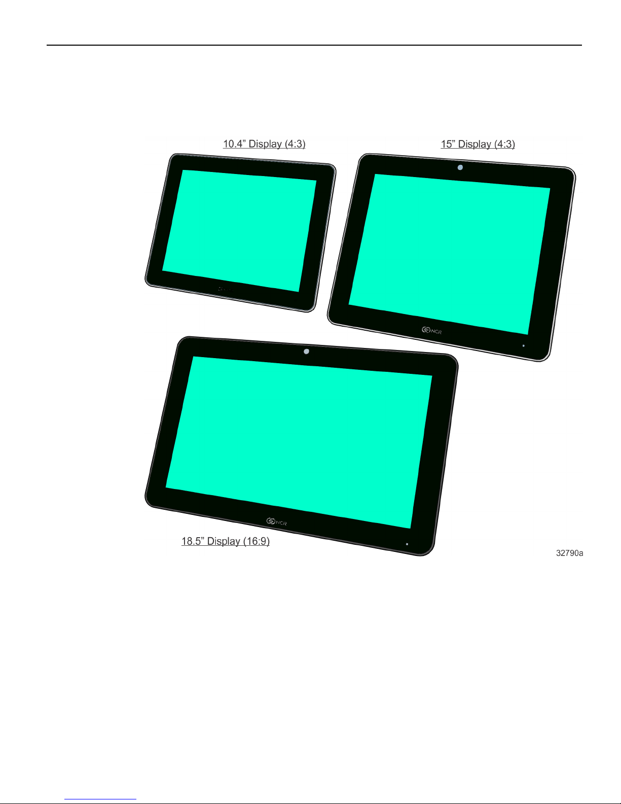
The NCR RealPOS X-Series Displays are available with a 10.4" (4:3), 15” (4:3), or 18.5”
(16:9) display. Place it on a tabletop, or hang it on a wall or a pole. You can also
customize your solution with integrated options including an encrypted magnetic
stripe reader (MSR), biometric fingerprint reader, or camera.
Page 12
1-2 Product Overview
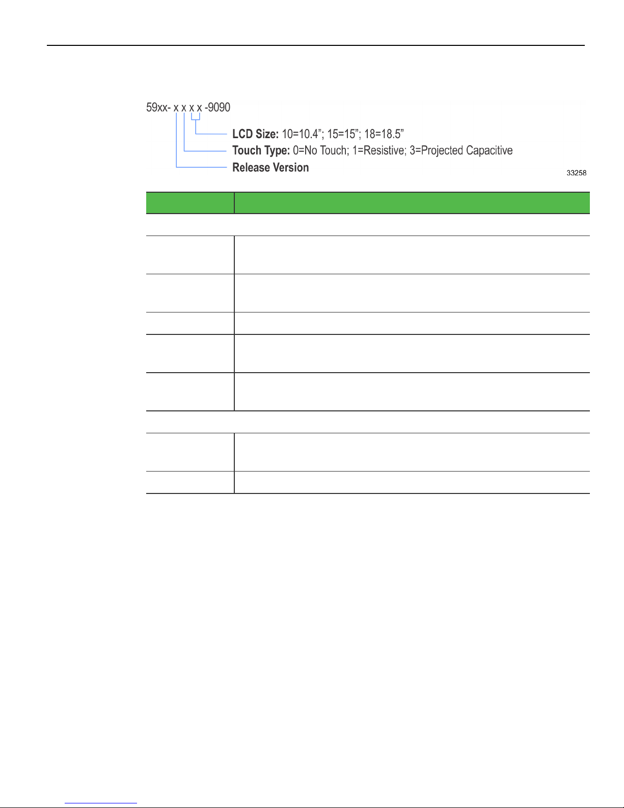
Product IDs
Major Model Description
5968
5968-2110-9090 RealPOS XT10: 10.4" Resistive Touch Display with Port B, No Mount,
No MSR
5968-1310-9090 RealPOS XT10: 10.4" Projected Capacitive Touch Display, No Mount,
No MSR
5968-1115-9090 RealPOS XT15: 15" Resistive Touch Display, No Mount, No MSR
5968-1315-9090 RealPOS XT15: 15" Projected Capacitive Touch Display, No Mount,
No MSR
5968-1318-9090 RealPOS XT18: 18.5" Projected Capacitive Touch Display, No Mount,
No MSR
5985
5985-2010-9090 RealPOS XD10: 10.4" LEDBacklight Display with Port B, No Mount,
No MSR
5985-1015-9090 RealPOS XD15: 15" LEDBacklight Display, No Mount, No MSR
Page 13

Product Overview 1-3
Standard Features
• Display
• Display Size: 10.4" (4:3 aspect ratio), 15" (4:3 aspect ratio), 18.5" (16:9 aspect ratio)
• LCD Technology: TFT; Pixel Configuration: RGB
• LCD LED Backlit Technology
• Viewing Direction: 12 o'clock
• Minimum Backlight ½ Life at Rated Luminance: 50,000 hours
• LCD LED Backlight: Controllable using the Software OSD Application
• Touch Sensor (5968): Resistive/Projected Capacitive
• Touch Interface: USB
• Video Interface: DisplayPort, HDMI, VGA, DVI through HDMI
• Physical Mounting Interface: NCRcustom and VESA 75mm/100mm mounting
compliance
• Flexible Cable Length Options (compatibility with NCR 1m and 4m external cables)
• Clean (Hidden) Cable Management
• Retail Hardened Display
• Integrated Enclosure
• Optional MSR/Biometric Reader/Imager Mounting Locations
• Rigid Mounting Attachments
• Latching/Strain-relieved Cables used where possible
• Spill-proof (front) and dust-proof (front)
• Integrated Amplified Speakers
Optional Features
• Table Top Stands
• Magnetic Stripe Reader (Encrypted 3-track or JIS)
• Biometric Fingerprint Reader (15" and 18.5" Displays only)
• Capacitive Biometric Reader (5968 15" and 18.5" Displays only)
• Imager
• Keypad (5968 15" Display only)
• Integrated Camera (5968 15" and 18.5" Displays only)
• Terminal Power Option (USB PlusPower)
Page 14

1-4 Product Overview
Compatibility
The NCRX-Series Display is designed as an optional input/output device for the
following host terminals:
• NCR RealPOS 30 (7446) POS Terminal
• NCR RealPOS 40 (7600) POS Terminal
• NCR RealPOS 60 (7601) POS Terminal
• NCR RealPOS 70 (7402) POS Terminal
• NCR RealPOS 70XRT (7403) POS Terminal
• NCRRealPOS 72XRT (7616) POSTerminal
• NCR RealPOS 80c (7457) POS Terminal
• NCR RealPOS 80 (7458) POS Terminal
• NCR RealPOS 80XRT (7459) POS Terminal
• NCR RealPOS 82XRT (7606) POS Terminal
• NCR RealPOS XR7 (7702) POS Terminal (10.4" and 15" Only)
Supported Resolutions
Display Resolution
5968
10.4" Resistive Touch 640x480, 800x600 (native)
10.4" Projected Capacitive Touch 640x480, 800x600 (native), 1024x768
15" Resistive Touch 640x480, 800x600, 1024x768 (native)
15" Projected Capacitive Touch 640x480, 800x600, 1024x768 (native), 1280x1024
18.5" Projected Capacitive Touch 640x480, 800x600, 1024x768, 1280x1024,
5985
10.4" Non-Touch 640x480, 800x600 (native)
1366x768 (native)
15" Non-Touch 640x480, 800x600, 1024x768 (native)
Page 15
Product Overview 1-5
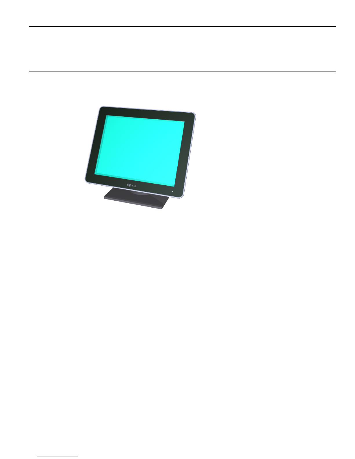
Configurations
Display
Page 16
1-6 Product Overview
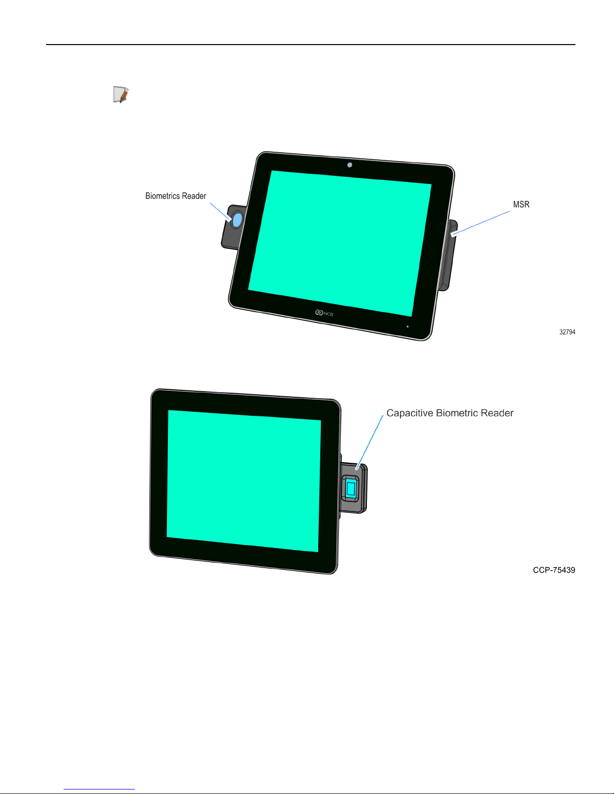
Biometrics and MSR (Encrypted 3-track or JIS)
Note: Biometrics available on 15" and 18.5" displays only. JISMSR available on 10.4" and
15" displays only.
Capacitive Biometric Reader (5968 15" and 18.5" Displays Only)
Page 17
Product Overview 1-7
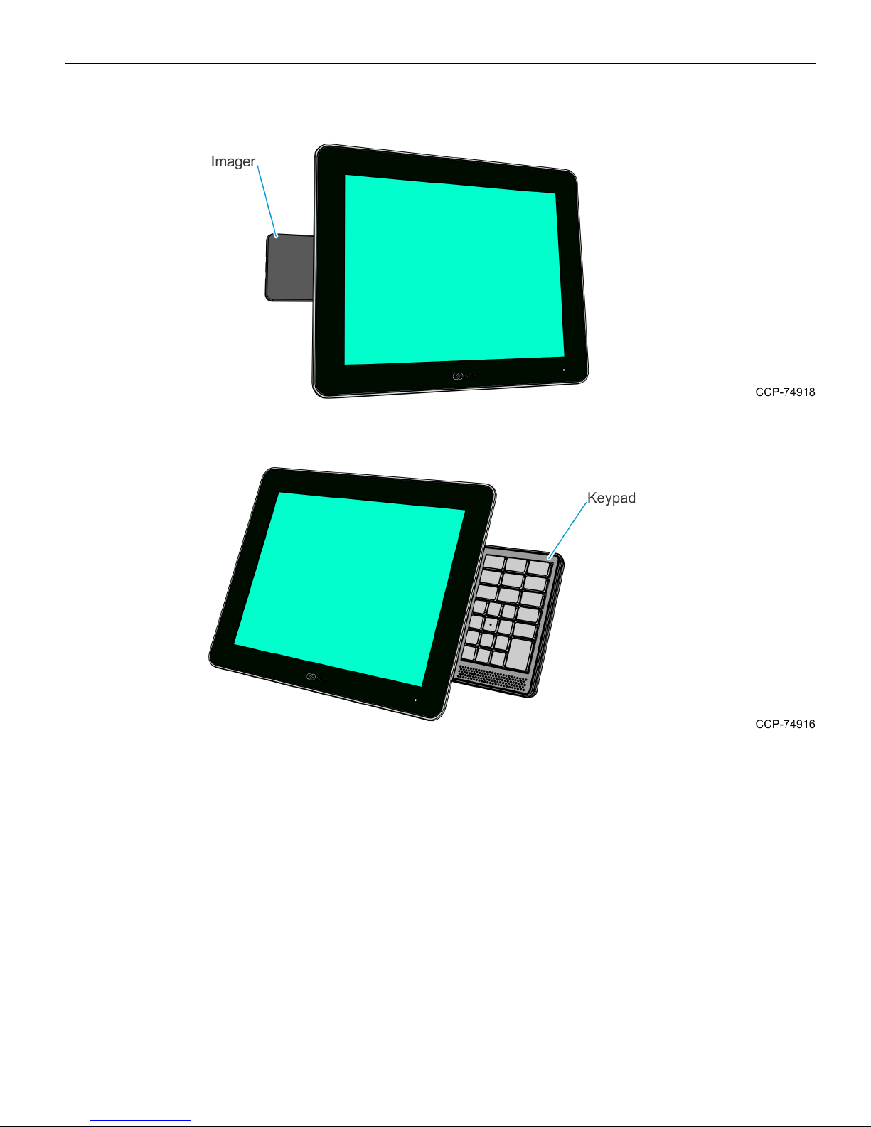
Imager
Keypad (5968 15" Display Only)
Page 18
1-8 Product Overview
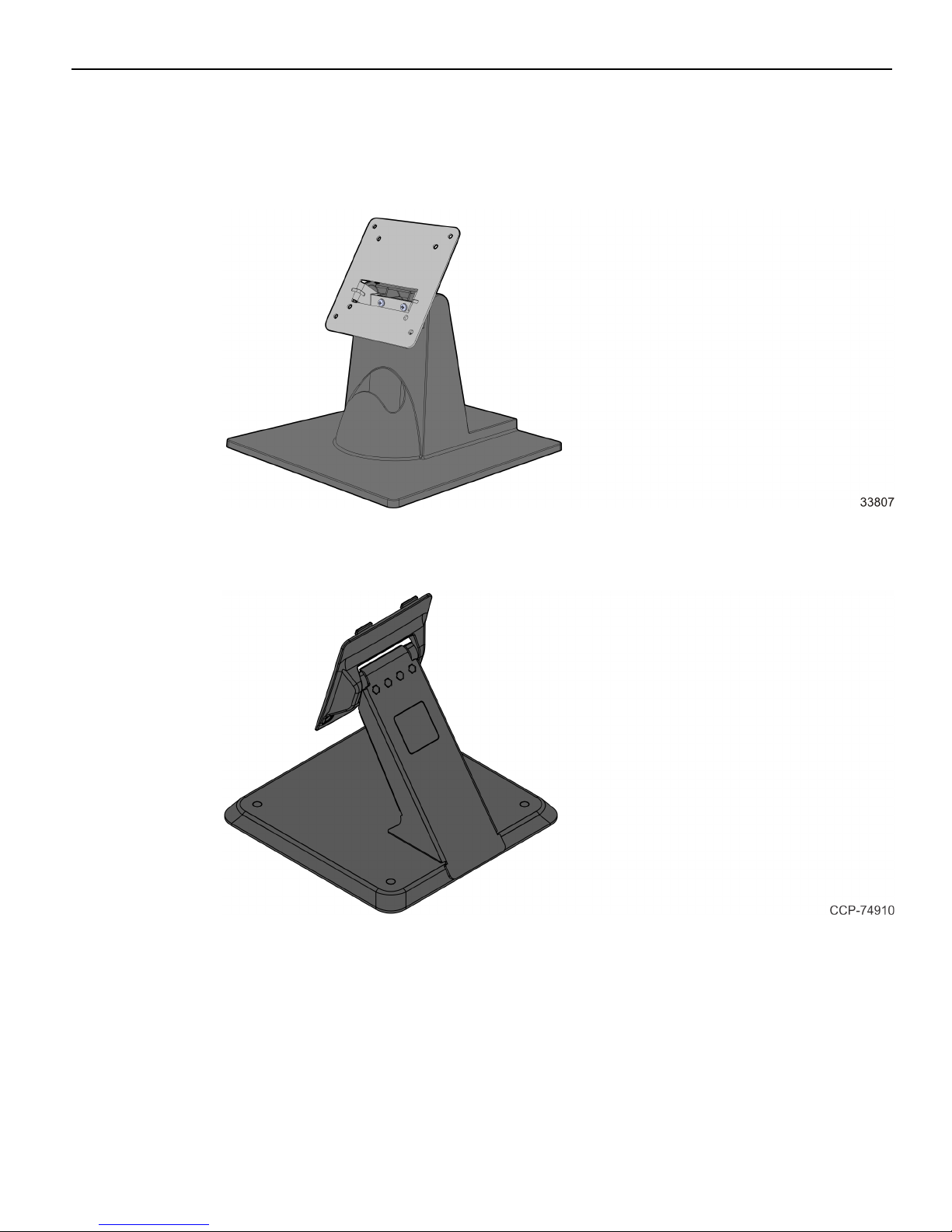
Display Mounts
X-Series Table Top Stand (5968-F031/K031, 5985-F031)
XL Series Table Top Stand (5968-F033, 5915-K033)
Page 19
Product Overview 1-9
XR Series Table Top Stand with Power Brick (7702-K031)
Integration Tray Mount (5968-K024)
Checkstand Mount (5968-K039)
Page 20

1-10 Product Overview
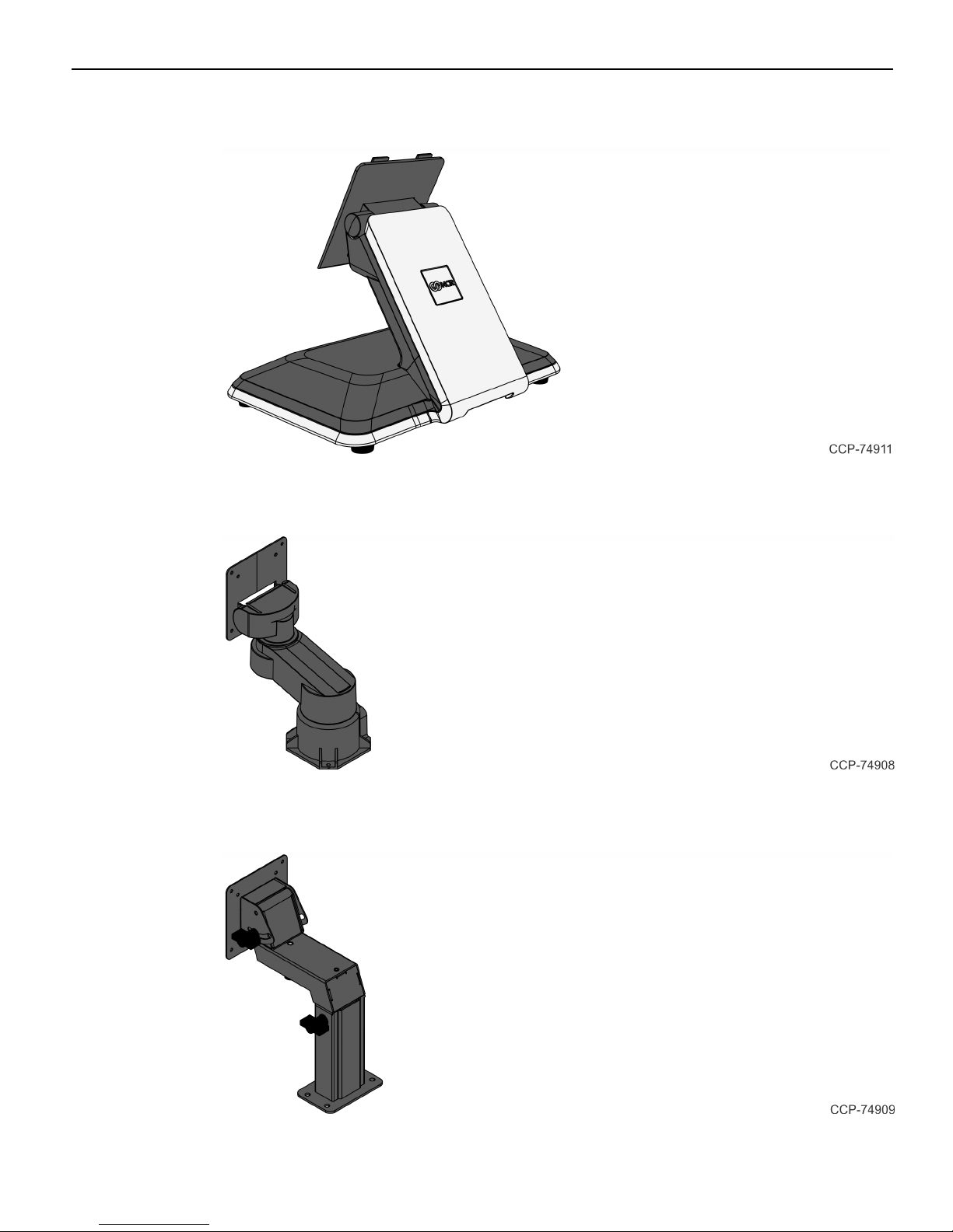
Wall Mount (7702-K320)
VESAMount Spacer (7702-K321, For 10.4" and 15" Displays Only)
The Rear Cover has a VESA Pattern to accommodate Third-Party Mounts. A VESA
Mount Spacer (7702-K321) is available for when the VESA mount is larger than the inset
in the Rear Cover, which provides a flat surface for the mount.
Page 21

Product Overview 1-11
X-Series Display Extension Arm Mount (7702-K453, For 10.4" and 15"
Displays Only)
This mount (7702-K453) is used to add an X-Series Display as a second display on an
XRSeries Stand (7702-K031). The second display is mounted on an Extension Arm
connected to the bottom of the Stand. The XRSeries Stand and the interface cables to
the host terminal are not included and must be ordered separately.
Pole Mount (For 5985 10.4" Display Only)
12" Pole and Table Top Mount (5934-K020) and Pole Mount Head
for 10.4" Non-Touch Display (5985-F300)
Must order both 5934-K020 and 5985-F300.
Page 22

1-12 Product Overview
Power Indicator
The Front Panel Power LED has multiple functions as defined below.
Color Description
Black System OFF or No power
Blue System ON
Green (1 sec.) Searching for an active video signal
Note: The display does not have an ON/OFF power switch.
Page 23

Product Overview 1-13
Label Locations
Page 24

1-14
Page 25

Chapter 2: Hardware Installation
Installation Restrictions
• Before installing the NCR RealPOS X-Series Display, read and follow the guidelines
in the RealPOS X-Series Displays (5968/5985) Site PreparationGuide (BCC5-0000-5292)
and the NCR Workstation and Peripheral AC Wiring Guide (BST0-2115-53).
• Install the display near an electrical outlet that is easily accessible. Use the power
cord as a power disconnect device.
• Do not permit any object to rest on the power cord. Do not locate the display
where the power cord can be walked on.
• Use a grounding strap or touch a grounded metal object to discharge any static
electricity from your body before servicing the display.
Caution: This unit contains hazardous voltages and should only be serviced by
qualified service personnel.
Caution: This device should only be powered by a power supply source which meets
Safety Extra Low Voltage (SELV) and LPS (Limited Power Source) requirements per
UL1950, IEC 950, and EN 60 950. The power source must be certified by the appropriate
safety agency for the country of installation.
Caution: Use a grounding strap when installing this feature.
Page 26

2-16 Hardware Installation
Ergonomic Workplace
The display has a high brightness LCD but for best results please observe the following
when considering the terminal workplace.
• Avoid direct–glaring and reflective–glaring light. Locate the terminal in a controlled
luminance surrounding. When installed next to windows position the terminal so it
does not reflect the outside light.
• If possible, avoid reflective glaring caused by electric light sources.
• Position the terminal for ideal viewing angles.
Page 27

Hardware Installation 2-17
Installing the Display
The display can be mounted using a variety of mounts.
• X-Series Table Top Stand (5968-F031/K031, 5985-F031)
• XL Series Table Top Stand (5968-F033, 5915-K033)
• XRSeries Table Top Stand (7702-K031)
• Integration Tray Mount (5968-K024)
• Checkstand Mount (5968-K039)
• Wall Mount (7702-K320)
• X-Series Display Extension Arm (7702-K453, For 10.4" and 15" Displays only)
• Pole Mount (5985-F300 with 5934-K020, For 5985 10.4" Display only)
• Third-Party VESA Mounts
This chapter explains how to perform an "Out-of-box" installation of a display
configured with the X-Series Table Top Stand (5968-F031/K031, 5985-F031) and how to
connect cables. The display comes fully assembled and ready to use. All that is required
to install is connect the AC Power Cord and host terminal cables.
For installation procedures for the other mounting options see their associated kit
instructions.
Page 28

2-18 Hardware Installation
Connecting the Host Terminal Cables
1. Unpack the display in the desired location.
2. Pivot the display toward the back.
Page 29

Hardware Installation 2-19
Connecting to a POS
The following illustrations show the host terminal cable connections. The required
cables vary depending on the available video connectors on the host terminal.
Data and Power Connections
Powered USBCable
The Powered USBCable provides both USB and power to the display.
1. Connect the Powered USB Cable to the display Power connector.
2. Connect the Powered USBCable to one of the 12V Powered USB connectors on the
host terminal.
Page 30

2-20 Hardware Installation
External Power Cables
An External Power Cable provides both USB and power to the display when the host
terminal does not have a USB 12V port available, but does have an available standard
USB port.
1. Connect the External Power Cable to the display Power connector.
2. Connect the other end of the External Power Cable to the USB connector on the host
terminal.
3. Connect the Power Brick DC Cable to the External Power Cable (middle of the
cable).
4. Connect the AC Power Cord to the Power Brick and an AC outlet.
Page 31

Hardware Installation 2-21
Video and Audio Connections
DisplayPort Cable
The DisplayPort Cable provides both video and audio to the display.
• Connect the DisplayPort Cable to the DisplayPort connectors on both the display and
the host terminal.
Page 32

2-22 Hardware Installation
HDMI Cable
The HDMI Cable provides both video and audio to the display.
• Connect the HDMI Cable to the HDMI connectors on both the display and the host
terminal.
Page 33

Hardware Installation 2-23
DVI to HDMICable
If the host terminal does not have an HDMI port you can use the DVI to HDMI Cable
for video to the display. A separate Audio Cable is required for audio.
1. Connect the DVI end of the cable to the DVI connector on the host terminal.
2. Connect the HDMI end of the cable to the HDMI connector on the display.
3. Optional: Connect an Audio Cable to the Audio connectors on both the display and
host terminal.
Page 34

2-24 Hardware Installation
VGA Cable
For host terminals that only have VGAfor video, a VGA Cable can be used to provide
video to the display. A separate Audio Cable is required for audio.
1. Connect the VGA Cable to the VGA connectors on both the display and host
terminal.
2. Optional: Connect an Audio Cable to the Audio connectors on both the display and
host terminal.
Note: The display has an internal audio amplifier. In order to obtain high quality
speaker output the connection from the host terminal should be driven with a Line
level signal and NOT by an Amplified or Speaker level signal. If an Amplified or Speaker
level signal is the only connection option, the volume on the terminal should be
reduced to eliminate audio distortion.
Page 35

Hardware Installation 2-25
Cable Routing
Routing Cables for Strain Relief
The display features a zip tie attachment to prevent cable strain on the cable connectors.
Cables are zip tied together at the display head and routed into the mount or stand. An
extended latch is featured on the reusable zip tie to aid with quick removal without
cutting the tie or damaging the wires.
Caution: Do not cut the zip tie.
1. Route the cables up though the mount or stand.
2. Insert the cables into their respective sockets.
3. Open the zip tie by disengaging the zip tie latch from the "teeth." Use fingernail or
small screw driver to gently disengage the latch.
Page 36

2-26 Hardware Installation
4. Bend the cables at a right angle so they cross horizontally into the open zip tie.
Note: Allow enough slack in the cables prior to closing the reusable zip tie.
5. Tighten the zip tie firmly to keep the cables in place.
6. To remove the cables, use fingernail or small screw driver to gently disengage the zip
tie latch and loosen the zip tie.
Caution: Do not cut the zip tie.
Page 37

Hardware Installation 2-27
Note: The cable management location differs slightly depending on the screen size. The
10.4" display has an added plastic zip tie mount and the 15" display has a molded zip tie
mount. Both are located at the bottom and back of the display.
Page 38

2-28 Hardware Installation
X-Series Table Top Stand (5968-F031/K031, 5985-F031)
The X-Series Table Top Stand includes a hook and loop cable management wrap to
properly route the cables though the bottom of the stand.
1. Complete the steps for cable management on the display head.
2. Adjust the display head so it is rotated as far as possible to access the connectors.
This ensures a large enough service loop to minimize strain.
3. Secure the cables with the hook and loop wrap.
Page 39

Hardware Installation 2-29
XRSeries Table Top Stand (7702-K031)
Cables are routed out the opening in the Cable Cover and down through the Stand.
1. Complete the steps for cable management on the display head.
2. Adjust the display head so it is rotated as far as possible to access the connectors.
This ensures a large enough service loop to minimize strain.
3. Remove the Upper Stand Cover by pivoting it away from the stand. The cover has a
simple snap fit connection at the top.
4. Open the Base Cable Cover (captive thumb screw).
Page 40

2-30 Hardware Installation
5. Route the cables down through the opening in the Stand Base.
6. Close the Base Stand Cover and secure it with the Captive Thumb Screw.
7. Replace the Upper Stand Cover.
Page 41

Hardware Installation 2-31
Third-Party Mounts
VESAMount Spacer
The Rear Cover has a VESA Pattern to accommodate third-party mounts. A VESA
Mount Spacer (7702-K321) is available for when the VESA mount is larger than the inset
in the Rear Cover, which provides a flat surface for the mount.
Page 42

2-32 Hardware Installation
Mounting Screw Length
Mount the VESAMount Spacer (7702-K321) and the third-party mounting plate on the
back of the display. The required screw length depends on the thickness of the thirdparty mounting plate.
Note: For 10.4" RealPOSX-Series Displays, use the 75 mm pattern on the VESA Mount
Spacer. For 15" RealPOSX-Series Displays, use the 75 mm or 100 mm pattern.
Page 43

Hardware Installation 2-33
Use the below table to determine the proper screw to use.
Mounting Plate Thickness Screw Size Screw Description
0.5mm – 2mm M4 x 14 Steel Pan Head with SEMS Washer
2mm – 4mm M4 x 16 Steel Pan Head with SEMS Washer
4mm – 6mm M4 x 18 Steel Pan Head with SEMS Washer
6mm – 8mm M4 x 20 Steel Pan Head with SEMS Washer
8mm – 10mm M4 x 22 Steel Pan Head with SEMS Washer
10mm – 12mm M4 x 24 Steel Pan Head with SEMS Washer
Page 44

2-34
Page 45

Chapter 3: Operation and Cleaning
Touch Screens
There are two types of touch screens for the RealPOS X-Series Display (5968):
• Projected Capacitive (PCap) Touch Screen
• Resistive Touch Screen
Projected Capacitive Touch Screen
PCap touch screens have all the benefits of normal capacitive touch screens and more.
• Fast processing of tough information
• High sensitivity (use conductive pencils, with hands, and with thin gloves.
• Multi-touch capability (10-finger)
• High resolution
• Improved legibility and display brightness due to optimal light transmission
• Anti-glare surface
In addition, the technology of PCap touch screens is characterized by significantly
higher robustness and stability than common capacitive touch screens because the
active touch surface is located on the back side of the touch screen. instead of the front
side. Therefore, the active surface is not directly touched and does not wear off by
normal use.
Since most surface contamination do not cause interference to the touch screen the
RealPOS X-Series Display can be used in public or severe environmental conditions.
Using the PCap Touch Screen
The PCap touch screen responds to the lightest touches. Touching with a single finger
resembles the left mouse button. Two fingers are used to zoom IN (fingers brought
together) or zoom OUT (fingers pulled apart). Circular motion can be used to rotate an
element on the screen. This function must be supported by either the Operating System
or the application.
Page 46

3-36 Operation and Cleaning
Resistive Touch Screen
The resistive TFT touch screen is constructed of a hard-coated polyester top sheet that is
overlaid on a conductive-coated glass layer. Voltage is applied to the top sheet. As a user
touches the screen, the top sheet compresses and comes into contact with the glass
layer, causing current to flow to the four corners in proportion to the distance from the
edge. Ths controller then calculates the position of the finger, based on the current flow.
Because the controller derives both the "X" and "Y" touch coordinates from the stable
glass layer, ther accuracy and operation of the touch screen is unaffected by any damage
that may have occured to the top sheet.
Using the Resistive Touch Screen
The resistive touch screen functions as traditional single-touch screens.
Touch Screen Cleaning Procedures
1. Using a soft cloth dampened with isopropyl alcohol or a mild non-abrasive soap &
water solution, gently wipe the touch screen clean.
2. Wipe the screen and edges dry.
3. Make sure the glass and screen edges dry completely before using the unit.
4. Do not use sharp objects to clean around the edges of the touch screen.
Page 47

Operation and Cleaning 3-37
Magnetic Stripe Reader
There are two types of Magnetic Stripe Readers (MSR) for the display.
• ISO 3-Track (Encrypted)
• JIS
The card reading is bi-directional and can be mounted on the right side of the display.
Using the MSR
Swipe the card through the slot in the MSR in a quick and steady movement. The
magnetic stripe must be facing up and with the stripe in the slot.
Care of Cards
• Cards should never come in contact with liquids.
• Cards should never be bent or folded in any way.
• Cards should never come in close proximity of a magnetic field.
Card Thickness
The MSR module accepts standard cards within the thickness range of 0.68 – 0.84 mm.
Page 48

3-38 Operation and Cleaning
Biometrics Fingerprint Reader
High quality fingerprint templates are imperative for the security of the biometric
security system. Low quality fingerprint templates can impact future read rates.
Therefore, using the Biometrics Module should be done very carefully. In case of
inexperienced users who are using the module for the first time, the process should be
assisted (guided) by an administrator or experienced user.
Sensor Cleaning Procedures
Daily Cleaning
Before each authentication, it is recommended that the user first clean the sensor. Place
adhesive tape onto the sensor and then pull it off. This assures that residue from
previous usage is removed.
Caution: Do not use abrasive materials to clean the sensor, including paper products.
Only adhesive tape should be used.
Using the Biometrics Reader
Place your thumb/finger flat and straight on the sensor. If this is not possible, try to
place your thumb/finger on the sensor in the same angle every time.
Page 49

Operation and Cleaning 3-39
Under normal usage conditions dirt, residue, oils, and other materials can collect on
users’ fingers. This can possibly cause poor collection of fingerprint data, which can
cause performance degradation. For best results it is recommended that the user keep
their fingers relatively clean and free of residue that may alter the sensor performance.
Adhesive tape can be used to clean fingers. Adhere the tape to the finger and then pull
it off.
Software Drivers
The RealPOS Biometrics Readers use the following modules:
Feature/Kit
Number
5985-F151
5968-F151
Description Module For Display
Biometric Reader (Port B) DigitalPersona
U.are.U 4500 Module
5985 (15")
5968 (15" or 18.5")
7702-K151
5968-F154
5968-K154
Capacitive Biometric
Reader (Port A)
TouchChip TCET
Silicon Module
5968 (18.5")
utilizing sensor
TCETD1FG022
Please visit the Crossmatch website for drivers and application developer tools.
https://www.crossmatch.com/company/support/request/
Page 50

3-40 Operation and Cleaning
Cabinet Cleaning Procedures
1. Disconnect the unit from the power outlet before cleaning.
2. Use a cloth lightly dampened with a mild detergent.
3. Do not use alcohol (methyl, ethyl, or isopropyl) or any strong dis-solvent. Do not use
thinner or benzene, abrasive cleaners, or compressed air.
Warning: Do not use any other types of cleaners such as vinegar, solvents,
degreasers, or ammonia-based cleaners. These can damage the unit.
4. Avoid getting liquids inside the unit. If liquid does get inside, have a qualified
service technician check it before you power it on again.
Page 51

Chapter 4: NCR Software OSD Utility
Introduction
The NCR Software OSD is an application that is used to adjust display parameters, such
as brightness, contrast, and Color. It also provides monitor identification information,
such as the name, serial number, and manufacturer.
Supported Features
Note: Not all features are supported on every monitor. The button is inactive and
grayed out when the feature is not supported
• Brightness
• Contrast
• V Position
• H Position
• Phase
• Clock
• Red/Green/Blue Video Gain
• Color Temperature
• Auto Setup
• Restore Default Settings
• V Moire
• H Moire
• V Size
• H Size
Page 52

4-42 NCR Software OSD Utility
Installing the Utility
1. Download the OSD Utility from the NCR website: http://www.ncr.com
a.
At this site, select the Support tab.
b.
Select Drivers and Patches → Retail Support Files→ NCR RealPOS and
Peripherals→ Displays→ 5968.
c. Download the application.
There are several versions to choose from. There are GUI versions that are used to
run locally on each system or Console versions for customers who want to run the
application from a Command Line to many systems concurrently.
Windows
• NCR_Software_OSD_GUI_x86 - (32-Bit)
• NCR_Software_OSD_Console_x86 - (32-Bit)
• NCR_Software_OSD_GUI_x64 - (64-Bit)
• NCR_Software_OSD_Console_x64 - (64-Bit)
Linux
• NCR_Software_OSD_GUI_x86 - (32-Bit)
• NCR_Software_OSD_Console_x86 - (32-Bit)
2. Click on the version of choice and Save it on your local system.
3. Unzip the application to a folder of your choice on the target system.
4. In the unzipped folder, navigate to the OSD executable.
Example: (32-Bit GUI version)
NCR_Software_OSD_GUI_x86_V2.1.7.1 >> x86
5. Run the *.exe file.
NCR_Software_OSD_GUI_x86.exe >> [Enter]
6.
Answer Yes at the Security warning.
Page 53

NCR Software OSD Utility 4-43
Running the Utility (GUI Version)
1. Unzip the application to a folder of your choice on the target system.
2. In the unzipped folder, navigate to the OSD executable.
Example: (32-Bit version)
NCR_Software_OSD_GUI_x86_V2.1.6.3>> x86
3.
Execute the NCR_Software_OSD_GUI_x86.exe file to start the application.
4.
Answer Yes at the Security warning.
Main Menu
Monitors Detected Panel
This panel lists all the monitors connected to the system. If more than one monitor is
connected, the first monitor is selected by default.
Center Panel
The Center Panel displays information pertaining the selected control.
Page 54

4-44 NCR Software OSD Utility
Control Buttons
The Control Buttons show the available features that can be modified. Unavailable
features are grayed out.
Refresh Button
Refreshes data in the Monitors Detected panel (OSD does not auto detect). Use this
button after connecting a new monitor to refresh the data.
About Button
Displays a brief description of the utility.
Help Button
Opens the Help File.
Close Button
Closes the OSD application.
Information
Provides information about the selected monitor. Information includes:
• Device manufacturer
• Date manufactured
• EDID version
• Input type
• Dimensions
• Monitor name
• Monitor serial number
• Preferred timing
• Controller type
• Firmware level
• Firmware version (for Dynamo display only)
• Display mode (for Dynamo display only)
• Timing Report
• Horizontal frequency
• Vertical frequency
• Timing status
• Raw EDID
• Raw capabilities string (CAPS)
Page 55

NCR Software OSD Utility 4-45
Brightness
Provides tools for adjusting Display brightness settings.
Contrast
Provides tools for adjusting Display contrast settings.
Positioning
Provides tools for gradually moving the image on the Display to a specific region
(either left, right, up, or down).
Size
Provides tools for increasing or decreasing the height and width of the image on the
Display.
Phase
Provides tools for increasing or decreasing the phase shift of the sampling clock.
Clock
Provides tools for increasing or decreasing the video sampling clock frequency.
Colour
Provides tools for adjusting Display color settings.
Sharpness
Provides tools for increasing or decreasing the sharpness settings of the Display.
Restore
Provides the following functions:
• Auto Setup - sets horizontal position, vertical position, clock and phase.
• Auto Color - sets red/green/blue gain.
• Factory Defaults - restores all factory defaults including brightness, contrast, and
color.
• Brightness/Contrast - restores factory defaults for brightness and contrast.
• Geometry Settings - restores factory defaults for geometry settings such as
horizontal position and vertical position.
• Colour Settings - restores factory defaults for colour settings.
Degauss
Provides tools for CRT display to perform a degauss cycle.
Moire
Provides tools for increasing or decreasing the vertical or horizontal moiré picture
cancellation.
Page 56

4-46 NCR Software OSD Utility
Language
Provides listing of the supported languages and permits changing the OSD
language.
Display Adjustment Procedures
The adjustment procedures are similar for most features. The color adjustment shown
below is an example.
1.
Select the Colour button.
2. The default Colour Settings menu has the 6500K radio button selected. To activate
the color slides select User1 .
3. Drag the slider to the right to increase the value of the property or to the left to
decrease it. Alternatively, you can click on the "+" and "-" buttons.
Page 57

NCR Software OSD Utility 4-47
Resetting Factory Defaults
Should the need arise the display settings can be reset to the factory defaults.
1.
Select the Restore button.
2. All settings or just specific groups can be reset. Select the button of choice in the
Restore window.
• Auto Setup - re-positions the window in the center of the display
• Factory Defaults - resets everything to the factory defaults
• Brightness/Contrast - resets the brightness and contrasts settings only
• Color Settings - resets the color settings only
Page 58

4-48 NCR Software OSD Utility
Running the Utility (Console Version)
1. Unzip the downloaded application to a folder of your choice on the target system.
2. In the unzipped folder, navigate to the OSD executable.
Example: (32-Bit version)
NCR_Software_OSD_Console_x86_V2.1.7.1 >> x86
3. Open a Command Line dialog window.
4. From the Command Line dialog, navigate to the OSD executable (*.exe) file.
5. Execute the file to start the application.
NCR_Software_OSD_Console_x86.exe >> [Enter]
A list of the available script command options are displayed, followed by several
example scripts. If you need further assistance with creating scripts please contact
your NCR representative for help.
Page 59

Appendix A: Touch Screen Calibration
Note: Only units with resistive touch screens need to be calibrated. PCap displays do
not require calibration.
Proper Touch Screen Methods
Before performing the calibration procedure please observe the following guidelines for
proper/improper methods of touching the screen.
• Face the monitor directly.
• Perform the calibration in the position (sitting or standing) that you normally expect
to use the touch screen.
• Touch the calibration target firmly and precisely with your fingertip. During
calibration, be careful to keep your fingernails and other fingers away from the
touch screen as you touch each target.
• The hand and calibration finger should be perpendicular (straight up) from the
touch screen during touch down and removal of the calibration finger. Keep the
other fingers closed and away from the touch screen.
• Do NOT touch the bezel with your other fingers.
Page 60

A-50 Proper Touch Screen Methods
Calibrating the Touch Screen
Resistive Touch Screen Calibration
1. Run the calibration program.
a. Open Windows Explorer.
b. Navigate to the calibration program.
C: >> Install >> Touch >> Drivers >> Resistive Touch Calibartion
2. Touch the center of the cross-hair target. When the target is touched, it disappears
and another target appears.
3. Repeat the procedure for each target as they appear.
Page 61

Proper Touch Screen Methods A-51
PCap Touch Screen Calibration
PCap touch displays rarely need to be re-calibrated. However, if the need should arise
use the following procedure.
1. Run the calibration program.
Start >> Programs >> UPDD >> Calibrate
2. Touch the center of the cross-hair target. When the target is touched, it switches to a
green check mark.
3. Repeat the prodedure for each target as they appear.
Page 62

 Loading...