

Page 1

NCR RealPOS Value Touch Display
(5966 15-Inch)
Release 1.0
User Guide
B005-0000-1770
Issue D
Page 2

The product described in this book is a licensed product of NCR Corporation.
NCR is a registered trademark of NCR Corporation.
It is the policy of NCR Corporation (NCR) to improve products as new technology, components, software, and firmware become available.
NCR, therefore, reserves the right to change specifications without prior notice.
All features, functions, and operations described herein may not be marketed by NCR in all parts of the world. In some instances,
photographs are of equipment prototypes. Therefore, before using this document, consult with your NCR representative or NCR office for
information that is applicable and current.
To maintain the quality of our publications, we need your comments on the accuracy, clarity, organization, and value of this book.
Address correspondence to:
Manager, Information Products
NCR Corporation
2651 Satellite Blvd.
Duluth, GA 30096
Or send feedback:
http://www.info.ncr.com/eFeedback.cfm
Copyright © 2007
By NCR Corporation
Dayton, Ohio U.S.A.
All Rights Reserved
Page 3

i
Table of Contents
Chapter 1: Overview
Model Numbers ................................................................................ 1-1
Chapter 2: Site Preparation
Electrical Requirements .......................................................................... 2-1
5966 Electrical Requirements........................................................... 2-1
Store AC Wiring Requirements........................................................ 2-1
Environmental Requirements.................................................................. 2-2
Barometric Pressure.......................................................................... 2-2
Temperature...................................................................................... 2-2
Humidity ........................................................................................... 2-2
Weight ..................................................................................................... 2-2
Dimensions.............................................................................................. 2-3
5966 with Table Top Mount ............................................................. 2-3
5966 with 5964-K032 Table Top Mount.......................................... 2-3
System Cables ......................................................................................... 2-4
VGA Cable ....................................................................................... 2-4
12.1-Inch LCD Aux Power Cable..................................................... 2-4
Power Cords...................................................................................... 2-4
Chapter 3: Hardware Installation
Installing the 5966................................................................................... 3-1
Connector Panel Access.................................................................... 3-1
Mounting Options............................................................................. 3-2
Cable Routing ................................................................................... 3-2
Standard Integration Tray Display Mount (5964-K022/K023) .... 3-2
Standard Remote Table Top Mount (5964-K030/K031).............. 3-3
Connecting to a POS......................................................................... 3-4
Video Cable Connections ............................................................. 3-4
Data Cable Connections ............................................................... 3-5
Power Cable Connections............................................................. 3-6
Installing a 5964-K030/K031 Table Top Mount..................................... 3-7
Installation Procedures...................................................................... 3-7
Display Controls...................................................................................... 3-9
Power Indicator................................................................................. 3-9
On Screen Display (OSD)............................................................... 3-10
Menu Button............................................................................... 3-10
Select Button .............................................................................. 3-10
Page 4

ii
Navigate Up................................................................................ 3-10
Navigate Down........................................................................... 3-10
Power Button.............................................................................. 3-10
Screen Adjustment Operation Procedure........................................ 3-11
Chapter 4: OSD Adjustment
Main Menu .............................................................................................. 4-1
OSD Adjusting and Controls................................................................... 4-2
Chapter 5: Touch Screen Calibration - Windows
Installing and Calibrating the Touch Screen ........................................... 5-1
Installing the Driver and Utility........................................................ 5-1
4-Point Calibration Procedure .......................................................... 5-2
9-Point Linearization Procedure ....................................................... 5-5
Chapter 6: Touch Screen Calibration - Linux
Calibration Procedures ............................................................................ 6-1
4-Point Calibration Procedure .......................................................... 6-4
25-Point Linearization Procedure ..................................................... 6-8
Chapter 7: Auto Config Adjustment
Chapter 8: MSR Driver
Chapter 9: Maintenance
Cabinet and Touch Screen Cleaning Procedures..................................... 9-1
MSR Cleaning Procedures ...................................................................... 9-2
Appendix A: Technical Data
Display Timing........................................................................................A-2
Page 5

iii
Revision Record
Issue Date Remarks
A Feb 2007 First issue
B July 2007 Added Calibration Chapter
C Jan 2008 Added MSR Driver Chapter
D Mar 2009 Added Site Preparation Chapter; updated Hardware
Installation Chapter
Audience
This book is written for hardware installer/service personnel, system integrators, and field
engineers.
Note: This document is NCR proprietary information and is not to be disclosed or
reproduced without consent.
Safety Requirements
The NCR RealPOS 5966 conforms to all applicable legal requirements. To view the
compliance statements see the NCR RealPOS Peripherals Safety and Regulatory Statements
(B005-0000-1701).
Page 6

Page 7

1
Chapter 1: Overview
NCR’s RealPOS 5966 value touch display is designed and developed to provide a costeffective touch solution for retailers who want to maximize store productivity and extend the
life span of the touch display. The NCR 5966 is a 15-inch low cost XGA (1024x768) Liquid
Crystal Display with a 5-wire resistive touch screen for operator input.
It has the following features:
• 15’ LCD XGA (1024x768) Native Resolution, 160 nit Brightness
• Dual Bulb TFT LCD (also supports VGA, SVGA Resolutions)
• 5-Wire Resistive Touch, USB Interface
Model Numbers
• Video - VGA, Standard 15-Pin Female
• Integrated Stereo Speakers
• Power Supplied via AC Line Input or 12 DC Power Brick
• VGA, Touch, Speaker and Power Cables
• Remote Table Top Mount
• Optional MSR- Field Installable, USB Interface
• VESA standard 75mm mounting pattern on the back of the enclosure
• Uses NCR’s industry standard OPOS and JavaPOS drivers, supporting most applications
and standard NCR supported retail Windows and Linux operating systems.
Major Model Description
5966-1011 15” Value Resistive Touch Monitor, 350 nit, Remote Mount, Cables (G11)
5966-1012 15” Value Resistive Touch Monitor, 350 nit, Remote Mount, Cables (CG1)
Page 8

1-2 Chapter 1: Overview
Product Components
The 5966 is shipped with a Standard Table Top Mount. This mount can be replaced with an
NCR 5964-K030 (Beige) or NCR 5964-K031 (Charcoal) Table Top Mount if desired.
Note: When using the alternate mount the Vesa Adapter Plate is required (included with the
unit).
Also included with the unit:
• VGA cable for video
• USB cable for data
• Power Brick is included for when USB power is not available on the host terminal.
Note: The USB Power Cable is ordered separately.
• Audio cable (optional) - Connects to the Audio Connector on the 5966 and the Audio Out
port on the host computer.
5966 w/Propietary Mount Vesa Adapter Plate
VGA Cable
USB Cable
Audio Cable
DC Power Brick
AC Power Cord (U.S)
5966 w/5964-K030/K031 Mount
- 5964-K030 (Beige)
- 5964-K031 (Charcoal)
27331
Page 9

2
Chapter 2: Site Preparation
Electrical Requirements
5966 Electrical Requirements
The monitor's power cord plugs into a three-wire, single-phase, 120 or 240 VAC receptacle on
the monitor. The available power cords are described in the System Cables section.
120 volt 240 volt
Voltage Ranges 100 - 127 VAC 200 - 240 VAC
Frequency 50/60 Hz 50/60 Hz
Current (A) (Max.) 0.9 0.3
Store AC Wiring Requirements
The customer must provide suitable AC power for the monitor. A dedicated unswitched power
line dedicated to the NCR equipment installation is recommended. Refer to the NCR
Workstation and Peripherals AC Wiring Guide (BSTO-2115-53) for store AC wiring
requirements. The AC outlet must be installed near the monitor and easily accessible to the
operator.
Page 10

2-2 Chapter 2: Site Preparation
Environmental Requirements
Barometric Pressure
The terminal operates within the following barometric pressure conditions:
• Maximum operating altitude: 2,750 m (9,843 ft.)
• Operating range of pressure: 105 to 72.4 kPa (15.2 to 10.5 lb./in.)
Temperature
The terminal operates over the temperature ranges shown below. Continuous operation must
be avoided at or near the indicated temperature extremes or in locations where the temperature
changes beyond the restrictions.
Temperature Parameter Restriction
Operating
Storage
Humidity
The terminal operates within the humidity ranges shown below. Continuous operation must be
avoided at or near the indicated humidity extremes or in locations where the humidity changes
beyond the restrictions. Never expose the terminal to condensation.
0°C to 40°C (32°F to 104°F), dry bulb
-20°C to 60°C (-4°F to 140°F), three months
Weight
Humidity Type Restriction
Relative 15% to 85%
Storage 15% to 85%
Shipping 15% to 85%
5.4 kg (11.9 lbs.)
Page 11

Chapter 2: Site Preparation 2-3
Dimensions
5966 with Table Top Mount
400 mm
(15.7 in.)
220 mm
(8.7 in.)
358 mm
(14.1 in.)
394 mm
(15.5 in.)
5966 with 5964-K032 Table Top Mount
180 mm
(7.1 in.)
220 mm
(8.7 in.)
27328
400 mm
(15.7 in.)
230 mm
(9.0 in.)
358 mm
(14.1 in.)
394 mm
(15.5 in.)
254 mm
(10.0 in.)
220 mm
(8.7 in.)
27327
Page 12

2-4 Chapter 2: Site Preparation
System Cables
VGA Cable
Sub Miniature D-Shell
15-Pin Plug
12.1-Inch LCD Aux Power Cable
Power
497-0464066 - 1.8 m
(1432-C321-0018)
497-0428512 - 4 m (Black)
1416-C851-0040
Sub Miniature D-Shell
15-Pin Receptacle
Powered USB
27315
Power Cords
23226
Terminal/CRT
1416-C325-0030 006-1009037 - U.S.
The following power cables (not shown)
also have an IEC connection of 45 mm:
1416-C320-0030
1416-C321-0030
1416-C322-0030
1416-C323-0030
1416-C391-0030
1416-C393-0030
006-8601011 - SEV
006-8601012 - U.K.
006-8601019 - Australia
006-8601010 - International
006-8605488 - China
006-8601001 - Japan Twist-Lock
27304
Page 13

3
Chapter 3: Hardware Installation
Installing the 5966
Caution: This device should only be powered by a power supply source which meets Safety
Extra Low Voltage (SELV) and LPS (Limited Power Source) requirements per UL1950, IEC
950, and EN 60 950. The power source must be certified by the appropriate safety agency for
the country of installation.
Caution: Use a grounding strap when installing this feature.
Connector Panel Access
The 5966 peripheral cable connectors are located on the bottom of the assembly.
VGA AC PowerUSBAudio In DC Power
27320
Page 14
3-2 Chapter 3: Hardware Installation
Mounting Options
The 5966 is shipped with a unique 5966 table top mount. However it has a VESA standard
75mm mounting pattern on the back of the enclosure, which supports the following NCR
mounts.
• Integration Tray Mount, Beige (5964-K022)
• Integration Tray Mount, Charcoal (5964-K023)
• Table Top Mount, Beige (5964-K030)
• Table Top Mount, Charcoal (5964-K031)
• Checkstand Mount, Beige (5964-K038)
• Checkstand Mount, Charcoal (5964-K039)
The additional mounts are sold as kits and are ordered separately.
Note: There is a Vesa Adapter Plate included with the 5966 that must be used with the NCR
5964-K030/K031 mount.
Cable Routing
Standard Integration Tray Display Mount (5964-K022/K023)
• 5964-K022 (Beige)
• 5964-K023 (Charcoal)
Display Cover
Display Arm
Display Base
21202b
Page 15

Chapter 3: Hardware Installation 3-3
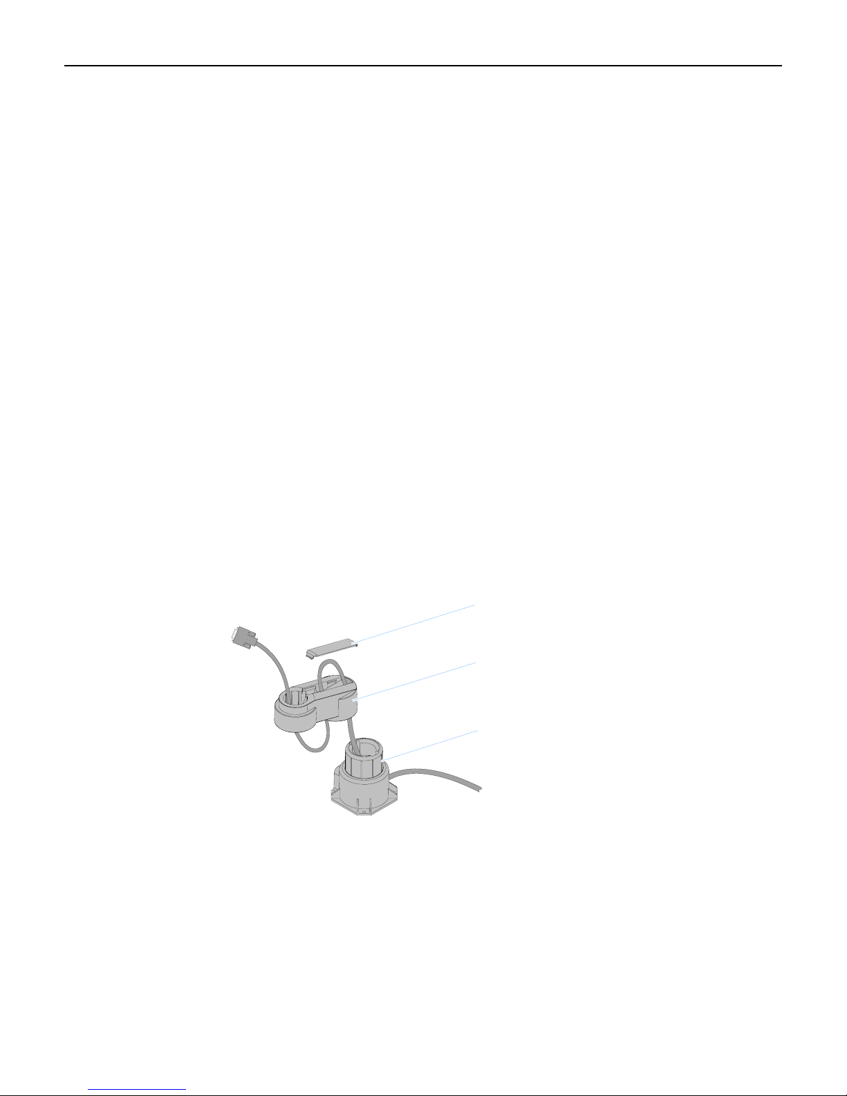
Standard Remote Table Top Mount (5964-K030/K031)
5966 w/Propietary Mount
5966 w/5964-K030/K031 Mount
- 5964-K030 (Beige)
- 5964-K031 (Charcoal)
27330
Page 16

3-4 Chapter 3: Hardware Installation
Connecting to a POS
The following illustrations show the cable connections for the 5966 and a host terminal. There
are two cables required.
• VGA cable for video
• USB cable for data
• Powered Universal Serial Bus (USB) for power
Note: Optional Power Brick is included for when USB power is not available on the host
terminal.
• Audio cable (optional) - Connects to the Audio Connector on the 5966 and the Audio Out
port on the host computer.
Video Cable Connections
Connect the VGA Cable to the VGA connectors on both the 5966 Touch LCD and host terminal.
RS232/C RS232/D
12V
USB/C
Mouse
RS232/B
Keybd. VGA DVI
RS232/A
USB/D
12V
12V
USB/H
USB/I
12V
12V
12V
24V
USB/F
Parallel
USB/G
VGA
Cash Drw
LAN
Line Out
Speaker
Mic
USB
VGA
USB/E
497-0435044 - 1m
(1416-C972-0009)
497-0435045 - 4m
(1416-C972-0040)
27319
Page 17

Chapter 3: Hardware Installation 3-5
Data Cable Connections
Connect the included USB Cable to the USB connector on the 5966 and to a USB connector on
the host terminal.
RS232/C RS232/D
12V
12V
USB/C
USB/D
Mouse
RS232/B
Keybd. VGA DVI
RS232/A
USB/E
12V
12V
USB/H
USB/I
12V
12V
24V
Cash Drw
USB/F
USB/G
LAN
Parallel
Line Out
Speaker
Mic
USB
USB
USB
27322
Page 18

3-6 Chapter 3: Hardware Installation
Power Cable Connections
There are three methods that can be used to supply power to the 5966.
• Powered USB Cable from the host terminal
• DC Power Brick (Included with the 5966)
• AC – A U.S. Power Cord is supplied with the 5966. International cords must be ordered
separately (See the System Cables section on Chapter 1).
RS232/C RS232/D
12V
12V
USB/C
USB/D
Mouse
RS232/B
Keybd. VGA DVI
RS232/A
USB/E
12V
12V
USB/F
Parallel
12V
12V
USB/H
USB/I
24V
Cash Drw
USB/G
12V USB
LAN
Line Out
Speaker
Mic
USB
or or
DC Power
497-0445076 - 1 m
(1432-C156-0010)
497-0445077 - 4 m
(1432-C156-0040)
AC Power Cord
(Country Specific)
AC
27321
Page 19

Chapter 3: Hardware Installation 3-7
Installing a 5964-K030/K031 Table Top Mount
The 5964-K030/K031 Table Top Mount can be used with the 5966 Display Head in place of
the Standard Mount shipped with the unit. There are two versions:
• 5964-K030 (Beige)
• 5964-K031 (Charcoal)
Installation Procedures
1. Lay the 5966 face down on a flat surface.
2. Remove the Standard Mount (4 screws) from the display.
Note: Discard these screws. The 5964 mount requires longer screws.
27338
Page 20

3-8 Chapter 3: Hardware Installation
3. Place the Vesa Adapter Plate in the recess in the back of the display.
4. Install the 5964 mount using the screws included with the mount.
5964-K030/K031 Mount
Vesa Plate
27329
Page 21

Chapter 3: Hardware Installation 3-9
Display Controls
Power Indicator
The LED is green color while in the normal ON state and orange while in the Power Save
mode.
Power Indicator
24316
Page 22

3-10 Chapter 3: Hardware Installation
On Screen Display (OSD)
The OSD is accessed through five pushbuttons on the rear of the display. These buttons
provide a way to adjust display parameters of the unit.
Menu Select
1
1
Navigate
Up
2
Navigate
Down
2
Power
24317
Menu Button
Used to enter the OSD menu. This button is also used to return to the previous menu. The
changed data is not saved in memory.
Select Button
Used to confirm the current selection. It also used for go back to the previous menu. The
changed data is saved in memory.
Navigate Up
Used to scroll up in sub menus or to increase the value of the selected item. Pressing this
button when a menu is not active adjusts the Brightness.
Navigate Down
Used to scroll down in sub menus or to decrease the value of the selected item. When the OSD
menu is not active this button is a shortcut key for the Auto Config function.
Power Button
Used to turn the monitor on/off.
Page 23

Chapter 3: Hardware Installation 3-11
Screen Adjustment Operation Procedure
1) Entering the screen adjustment
The setting switches are normally at stand-by. Push the [1] button once to display the main
menu of the screen adjustment. The adjustable items will be displayed in the main menu.
2) Entering the settings
Use the Adjust ▲ and Adjust ▼ buttons to select the desired setting icon and push the
SELECT button to enter sub-menu.
3) Change the settings
After the sub-menu appears, use the Adjust ▲ and Adjust ▼ buttons to change the setting
values.
4) Save
After finishing the adjustment, push the [2] button to memorize the setting.
5) Return & Exit the main menu
To go back to the previous menu, push the MEMU button.
Page 24

3-12 Chapter 3: Hardware Installation
Page 25

4
Chapter 4: OSD Adjustment
Main Menu
The On Screen Display (OSD) main menu is displayed when the [1] key is pressed. The menu
is a combination of graphics and text. The column inside the OSD menu shows input image
information. The column beneath the menu indicates the item selected.
The ▲ and ▼ keys are used to scroll through items within the menu. The selected item is
highlighted as you scroll. The [2] key is used to activate the highlighted item.
Page 26

4-2 Chapter 4: OSD Adjustment
OSD Adjusting and Controls
BRIGHTNESS
Setup the brightness of the panel.
CONTRAST
The Contrast menu item is used to adjust image contrast.
AUTO CONFIG
There are two items: AUTO ADJUST and AUTO COLOR . Use the Adjust ▲ and ▼ key to
scroll up and down in menu, then press the [2] key to start this function. If the MENU key is
pressed, the main menu is re-displayed and nothing is changed.
AUTO ADJUST: Used to perform automatic configuration of the phase, clock, vertical, and
horizontal positioning.
AUTO COLOR: It is used to adjust the gain and offset of the Red, Green and Blue channels
on the ADC automatically.
H-POSITION
H-Position is used to adjust the horizontal image position manually. A slider with current value
is displayed.
V-POSITION
V-Position is used to adjust the vertical image position manually. A slider with current value is
displayed.
CLOCK
Reduce vertical stripes in the screen image.
PHASE
Reduce horizontal stripes in the screen image.
SHARPNESS
This can adjust the video quality to be sharp or blur (special for text mode).
INFORMATION
The “INFORMATION” menu provides the user with detailed information regarding the
current input format and version (include resolution, horizontal/vertical frequency, and
firmware version).
Page 27

Chapter 4: OSD Adjustment 4-3
COLOR
Configure the image color. There are three items : 9300K、6500K、USER MODE.
9300K: The item “9300K” is used to default 9300K color temperature.
6500K: The item “6500K” is used to default 6500K color temperature.
USER MODE
RGB ADJUST :
• RED: The item “RED” is used to adjust the gain of red channel in ADC.
• GREEN: The item “GREEN” is used to adjust the gain of green channel in ADC.
• BLUE: The item “BLUE” is used to adjust the gain of blue channel in ADC.
OSD MENU
There are five items: LANGUAGE, OSD H POSITION, OSD V POSITION, , OSD TIME
OUT and OSD BLENDING.
• OSD H POSITION : The item "OSD H Position” is used to setup the OSD menu H
position.
• OSD V POSITION : The item "OSD V Position” is used to setup the OSD menu H
position.
• OSD BLENDING : To adjust the blending of the OSD MENU.
• OSD TIME OUT : “OSD Time out” is used to set the timeout of the OSD menu. There are
three options for the automatic timeout: 20, 40 and 60 seconds.
MISC MENU
There are two items: audio and reset.
• AUDIO: This is used to adjust the sound volume.
• RESET : Press “Reset” to return the monitor to its factory default settings.
Page 28

4-4 Chapter 4: OSD Adjustment
Page 29

5
Chapter 5: Touch Screen Calibration - Windows
Installing and Calibrating the Touch Screen
The Touch Screen Calibration Utility is included when you install the TouchKit Driver. This
driver can be downloaded from the NCR Web Site.
http://www.ncr.com
1. At this site, select Support → Drivers and Patches → Retail Support Files →
Retail Platform Software → 5966.
2. Download the Touch Driver: 5966_touch_driver_4.3.6.2817 (or later).
Installing the Driver and Utility
1. Extract the driver installation files into to a working directory on the host terminal.
2. Locate the folder containing the operating system you are using and run the setup program.
The name of the setup program varies from OS to OS. Follow the instructions to install the
software
Page 30

5-2 Chapter 5: Touch Screen Calibration - Windows
4-Point Calibration Procedure
Note: The 9-Point Linearization procedure should be performed first if either the Touch
Screen Sensor or the Controller Board is replaced.
1. From the Windows Start button, select
Settings → Programs → TouchKit → Configure Utility
2. From the TouchKit:USB Controller screen, select the Tools tab.
Page 31

Chapter 5: Touch Screen Calibration - Windows 5-3
3. Select 4-Points Calibration to begin calibration.
Page 32

5-4 Chapter 5: Touch Screen Calibration - Windows
4. Place a stylus in the center of the flashing target in the lower left-hand corner of the screen
and hold it until it stops blinking.
Note: For best results, a stylus should be used to calibrate the screen rather than your
finger. Not all operators use the same touching techniques and can result in poor
calibration on terminals that have multiple operators.
5. Repeat this procedure for the other three targets
6. Select OK to continue.
7. Test the calibration by moving the stylus around on the screen and verifying that the cursor
follows it. Also, touch all 4 Corners and verify that the cursor moves deeply into the
corners.
8. If you are satisfied with the calibration results select OK to exit the TouchKit Utility.
Page 33

Chapter 5: Touch Screen Calibration - Windows 5-5
9-Point Linearization Procedure
The 9-Point Linearization procedure should be performed if either the Touch Screen Sensor or
the Controller Board is replaced.
Note: On new terminals the display is pre-linearized from the factory and performing the
linearization procedure can result in loss of the factory settings and reduced performance
1. Select the Linearization button to begin the linearization process.
Page 34

5-6 Chapter 5: Touch Screen Calibration - Windows
2. Place a stylus in the center of the flashing target in the lower left-hand corner of the screen
and hold it until it stops blinking.
Note: As with the Calibration Procedure for best results a stylus should be used rather
than your finger.
3. Repeat this procedure for the other eight targets.
4. Select OK to continue.
5. Perform the 4-Point Calibration procedure.
Page 35

6
Chapter 6: Touch Screen Calibration - Linux
Calibration Procedures
The Touch Screen Calibration Utility is included in the NCR Linux Terminal Configurator,
which gets installed when you install the NLPOS Linux software.
For more information about the Terminal Configurator, see the NCR Linux Terminal
Configurator User's Guide, B005-0000-1743.
1. Start the Terminal Configurator Utility. At the prompt enter:
TerminalConfig
2. At the Main Menu, select: 2) Video.
Page 36

6-2 Chapter 6: Touch Screen Calibration - Linux
3. Select: 1) Adapter.
4. Select: 9) Calibrate Touch.
Page 37

Chapter 6: Touch Screen Calibration - Linux 6-3
5. Press any key to continue.
Page 38

6-4 Chapter 6: Touch Screen Calibration - Linux
4-Point Calibration Procedure
Note: The 25-Point Linearization procedure should be performed first if either the Touch
Screen Sensor or the Controller Board is replaced.
1. From the TouchKit window, select the Tool tab.
Page 39

Chapter 6: Touch Screen Calibration - Linux 6-5
2. Select 4-Pts Cal to start the calibration.
Page 40

6-6 Chapter 6: Touch Screen Calibration - Linux
3. Place a stylus in the center of the flashing target in the lower left-hand corner of the screen
and hold it until it beeps.
Note: For best results, a stylus should be used to calibrate the screen rather than your
finger. Not all operators use the same touching techniques and can result in poor
calibration on terminals that have multiple operators.
Please Touch The Calibration Symbol (ESC to Abort)
Toolkit Calibration
4. Repeat this procedure for the other three targets.
5. Select OK to continue.
24913
6. Test the calibration by moving the stylus around on the screen and verifying that the cursor
follows it. Also, touch all 4 Corners and verify that the cursor moves deeply into the
corners.
7. If you are satisfied with the calibration results select OK to exit the TouchKit Utility.
Page 41

Chapter 6: Touch Screen Calibration - Linux 6-7
8. Select OK to continue.
Page 42

6-8 Chapter 6: Touch Screen Calibration - Linux
25-Point Linearization Procedure
The 25-Point Linearization procedure should be performed if either the Touch Screen Sensor
or the Controller Board is replaced.
Note: On new terminals the display is pre-linearized from the factory and performing the
linearization procedure can result in loss of the factory settings and reduced performance
1. Select the 25 Pts Linz button to begin the linearization process.
Page 43

Chapter 6: Touch Screen Calibration - Linux 6-9
2. Place a stylus in the center of the flashing target in the lower left-hand corner of the screen
and hold it until it beeps.
Note: As with the Calibration Procedure for best results a stylus should be used rather
than your finger.
Please Touch The Calibration Symbol (ESC to Abort)
Toolkit Calibration
3. Repeat this procedure for the other 24 targets.
4. Select OK to continue.
5. Perform the 4-Point Calibration procedure.
24913
Page 44

6-10 Chapter 6: Touch Screen Calibration - Linux
Page 45

7
Chapter 7: Auto Config Adjustment
How to Use the Auto Config Adjustment
This function can tune the parameters of PHASE, CLOCK, H-POSITION, and VPOSITION.
Suggesting Adjustment Steps:
1. Enter the “Windows” Shut-down frame.
Note: The Wallpaper color CAN NOT be black.)
2. Inactive OSD menu, then press knob ▼ key. The Picture will auto-adjust by itself. After 4
seconds, you can exit OSD and Shut-down frame.
Notes:
• If you do not like the effect of the AUTO CONFIG adjustment, you can adjust the PHASE
and CLOCK items using the OSD.
• The AUTO CONFIG adjustment can be used in Windows except with a black background
frame. The best effect is in the SHUT DOWN frame.
Page 46

7-2 Chapter 7: Auto Config Adjustment
Page 47

8
Chapter 8: MSR Driver
The 5966 MSR is a USB device with unique drivers that need to be loaded to enable it.
The drivers are contained within Retail Platform Software (2.4.3.0 or 2.5.0.0) in the directory
C:\Program Files\NCR\Retail Controls\Drivers, or can be downloaded from the
NCR Web Site.
http://www.ncr.com
1. At this site, select Support → Drivers and Patches → Retail Support Files →
Retail Platform Software.
2. In the Peripherals section select 5966.
3. Download the 5966MSRDrivers.ZIP file.
4. Copy the file to a working directory on the target retail terminal and extract the files.
5. Right-click on the *.inf file to begin the installation process.
The device is from XAC and should appear as Vendor ID 2182 Product ID 8000. UPOS
support is provided for this device.
Page 48

8-2 Chapter 8: MSR Driver
Page 49

9
Chapter 9: Maintenance
Cabinet and Screen Cleaning Procedures
NCR touch screen terminals are designed for general retail applications. These products are
resistant to spills and dust. However, these products are not spill proof or dust proof.
To maintain proper operation, users should prevent water, beverages, or cleaning agents from
being introduced into the unit during storage, operation, or cleaning.
To clean your terminal, use the following procedures:
1. Disconnect the unit from the power outlet before cleaning.
2. Use a soft cloth dampened lightly with a mild non-abrasive soap & water solution or 70%
Isopropy
l Alcohol.
3. Gently wipe the subject area clean.
4. Wipe the damp areas dry. Make sure the glass and touch screen edges are completely dry
before using th
5. Avoid getting any liquids inside the unit. If liqui
technician check it before you power it on again.
e unit.
Cleaners/Solvents to Use
Use the following cleaner/solvents to clean the unit.
Mild Non-Abrasive Soap and Water Solution
or
70% Isopropyl Alcohol
Cleaners/Solvents to NOT Use
Do NOT use any of the following to clean the unit. They can damage the unit.
Methyl Alcohol
Degreasers
Ethyl Alcohol
Ammonia-based Cleaners such as glass cleaners (Windex)
Abrasive Cleaners
Vinegar Cleaners
Any Strong Dissolvent
Thinner
Benzene
Compressed Air.
Solvents
Bleach
d doe
s get inside, have a qualified service
Page 50

9-2 Chapter 9: Maintenance
Cleaning the Glass
1. Spray an ammonia-based glass cleaner on a soft cloth and gently wipe the glass screen
clean.
Warning: Do not use any other types of cleaners such as vinegar, solvents, or
degreasers. These can damage the screen.
2. Wipe the screen and edges dry.
3. Allow the glass and screen edges to completely dry before using the unit.
4. When cleaning has been completed, plug in the keyboard cable and power on the
workstation.
MSR Cleaning Procedures
MSR Cleaning and Treatment Cards
Part Part Number
MSR Cleaning Card, Dry 998-0052929
MSR Cleaning Card, Wet 603-9014730 (box of 50)
MSR Treatment Card 497-0453056 (box of 20)
MSR Treatment Card
The MSR Treatment Card is used to assist in protecting Magnetic Stripe Readers from
Electrostatic Discharge (ESD), which can cause failures when swiping cards that have metallic
hologram stripes.
Swipe the card through the MSR in a smooth motion. Only swipe it down ONCE and up
ONCE. Allow the device to dry for 5 minutes before swiping any other cards.
Note: Each long side of the card may be used twice. Each short side of the card may be used
only once. Thus, a single card can treat 6 MSR devices with one UP and one DOWN swipe per
MSR device. These limits should not be exceeded due to the possibility of spreading
contaminants from machine to machine and/or reducing ESD protection.
Page 51

Chapter 9: Maintenance 9-3
Note: If all six up/down swipes are not used on a fresh card it should be placed in a sealed
(Ziploc) bag for future use.
Cleaning/Treatment Frequency
New MSR:
Prior to placing in operation, the MSR device should be swiped with the MSR Treatment Card.
Existing MSR:
An existing MSR should be cleaned using an MSR Cleaning Card before treating it with a
MSR Treatment Card. For low use retail establishments, the cleaning and treatment procedures
should be followed at least once per month. In areas of extremely high traffic (in excess of 500
swipes per day) or an operating environment that is high in contaminants, such as found in the
food service industry, a weekly cleaning and treatment should be performed.
MSR Cleaning Cards and MSR Treatment Cards may be purchased from NCR or KIC
Products. For details, see
http://www.ncr-direct.com or http://www.kicproducts.com.
Page 52

9-4 Chapter 9: Maintenance
Page 53

A
Appendix A: Technical Data
Video Input Pin Assignment
This section describes the pin assignment of the LCD’s video connector. It is called 15 Pin
Mini D-sub Connector.
Pin NO. Signal Connector
1
2
3
4
5
6
7
8
9
10
11
12
13
14
Red Video Signal
Green Video Signal
Blue Video Signal
N.C.
Ground
Ground for red video signal
Ground for green video signal
Ground for blue video signal
VGA +5 V
PC detection
N.C.
DDC data
Horizontal sync signal
Vertical sync signal
15
DDC clock
Page 54

A-2 Appendix A: Technical Data
z
z
Display Timing
The following table lists the better display quality modes that the LCD monitor provides. If the
other video modes are input, the monitor will stop working or display unsatisfactory picture
quality.
VESA MODES
Horizontal Vertical VCLK
Mode Resolution Total Nominal
Frequency
+/- 0.5KHz
DOS 720*400@70Hz 900*449 31.469 70.087 28.322
VGA
SVGA
XGA
640*480@60Hz 800*525 31.469 59.940 25.175
640*480@72Hz 832*520 37.861 72.809 31.500
640*480@75Hz 840*500 37.500 75.000 31.500
800*600@56Hz 1024*625 35.156 56.250 36.000
800*600@60Hz 1056*628 37.879 60.017 40.000
800*600@72Hz 1040*666 48.077 72.188 50.000
800*600@75Hz 1056*625 46.875 75.000 49.500
1024*768@60Hz1344*804 48.363 60.004 65.000
1024*768@70Hz1328*806 56.476 70.069 75.000
1024*768@75H
1312*800 60.023 75.029 78.750
Nominal
Frequency
+/- 1 Hz
Nominal
Pixel Clock
(MHz)
IBM MODES
DOS 720*400@70Hz 900*449 31.469 70.087 28.322
VGA 640*480@60Hz 800*525 31.469 59.940 25.175
MAC MODES
640*480@60Hz 800*525 31.469 59.940 25.175
VGA
SVGA 832*624@75Hz 1152*667 49.725 74.551 57.283
XGA
640*480@75Hz 864*525 35.000 66.667 30.240
1024*768@60Hz1312*813 48.780
1024*768@75H
1328*804 60.241 74.927 80.000
60.001 64.000
 Loading...