

Page 1

NCR 5945 Electronic
Payment Terminal
Release 1.1
User's Guide
B005-0000-1104
Issue B
Page 2

ii User's Guide
The product described in this book is a licensed product of NCR Corporation.
IBM is a registered trademark of International Business Machines, Inc.
It is the policy of NCR Corporation (NCR) to improve products as new technology,
components, software, and firmware become available. NCR, therefore, reserves the
right to chan ge specificatio ns without prior notice.
All features, functions, and operations described herein may not be marketed by NCR
in all parts of the world. In some instances, photographs are of equipment prototypes.
Therefore, be f ore using this document, consult with your NCR representative or NCR
office for information that is applicable and current.
To maintain the quality of our publications, we need your comments on the accuracy,
clarity, organization, and value of this book.
Address correspondence to:
Retail Solutions Group−Atlanta
NCR Corporation
2651 Satellite Blvd.
Duluth, GA 30096
Copyright © 2000
By NCR Corporation
Dayton, Ohio U.S.A.
All Rights Reserved
Page 3

Table of Contents
Chapter 1:
Introduction
About this Manual..........................................................1-2
NCR 5945 Bookshelf.................................................1-2
NCR 5945 User’s Guide.......................................1-2
NCR 5945 Developer’s Guide.............................1-2
Installation.................................................................1-2
Basic Installation Kit............................................1-2
Chapter 2:
Installing the NCR 5945
About Installing and Operating....................................2-1
Unpacking the 5945..................................................2-1
5945 Location.............................................................2-2
Installation.................................................................2-2
Operating the 5945 ...................................................2-2
5945 Models and Accessory Kits............................2-3
Sliding Cards through the Card Reader................2-5
Maintenance.....................................................................2-5
Outside Interference.................................................2-5
Specifications...................................................................2-6
Operational Characteristics.....................................2-6
Compliance Listings.................................................2-7
Physical Interface......................................................2-7
Connecting the NCR 5945 to the NCR
7452/7453/7454 Workstation........................................2-8
Installation.................................................................2-8
Connecting the 5945 Connector..............................2-9
Disconnecting the 5945 Connector.......................2-10
Connecting the 5945 with a Power Supply.........2-10
Page 4

iv User's Guide
Cable Configurations.............................................2-11
Configuration 1...................................................2-11
Configuration 2...................................................2-12
Chapter 3
: Troubleshooting the NCR 5945
NCR 5945 Troubleshooting Table..........................3-1
Chapter 4:
Using the Supervisor Mode
Starting.......................................................................4-1
Password....................................................................4-2
Default Password.................................................4-2
Changing the Password......................................4-2
Operation..........................................................................4-3
Selecting Commands................................................4-3
Entering Alphanumeric Data..................................4-4
Main Menu Items............................................................4-5
CMDL.........................................................................4-5
Start App ...............................................................4-7
File Sys...................................................................4-7
ID Banner...............................................................4-7
Serial Number.......................................................4-7
Change Password.................................................4-7
Chapter 5:
NCR 5945 Diagnostics Specification
Startup Sequence ......................................................5-1
Operation..........................................................................5-2
Navigating through the Menu Items.....................5-2
NCR 5945 Keys.....................................................5-2
Menu Flow.................................................................5-3
Keypad Test...............................................................5-4
Display Test...............................................................5-5
MSR Test....................................................................5-6
Page 5

IBM 46xx Test............................................................5-7
Host RS232 Test/ AUX 1A RS232 Test/ AUX 1B
RS232 Test..................................................................5-9
Baud Rate Selection................................................5-10
Parity Selection........................................................5-10
Data Bit Selection....................................................5-11
Port Type..................................................................5-11
Test Selection...........................................................5-12
SRAM Test...............................................................5-13
Encryption Test.......................................................5-14
Key Check Value.....................................................5-15
Security Module Test .............................................5-16
OS Version Check/ Library Version/ Security
Version .....................................................................5-17
Exiting the Diagnostic screen................................5-17
Chapter 6
: Using the NCR 4430 Emulation Application
General.......................................................................6-1
If the Application Loads..........................................6-1
If the Sumcheck Fails................................................6-1
If the Sumcheck is Successful..................................6-2
4430 Emulation Application Setup.........................6-3
Card Data Format.....................................................6-3
SCER Account...........................................................6-3
Initiation of Buffering...............................................6-4
Changing the Initiated Buffering Type.............6-4
Repeating or Ending 4430 Setup ............................6-5
If Host Initiated Buffering is Currently
Specified.....................................................................6-5
If Host Initiated Buffering is Not Currently
Specified.....................................................................6-5
Running the NCR 4430 Emulation Application .........6-5
Page 6

vi User's Guide
Display Messages .....................................................6-5
Message Formats.............................................................6-6
EIA-232-D Interface..................................................6-6
Firmware/Software Identification.........................6-6
Specifying the Account Type..................................6-6
Function and Response Codes................................6-7
Abort Command (Function Code 51)....................6-7
If Using 4430-Initiated Buffering........................6-7
If Using Host-Initiated Buffering.......................6-7
Buffering Operations................................................6-8
Data Entry Sequence................................................6-8
If Using 4430-Initiated Buffering........................6-8
If Using Host-Initiated Buffering.......................6-8
Clear/Cancel Operations ........................................6-8
Reset Buffered Data (Function Code F1h).............6-9
If Using 4430-Initiated Buffering........................6-9
If Using Host-Initiated Buffering.......................6-9
Application Programming...........................................6-10
Special Function Keypad Input (Function Code
83h) ...........................................................................6-10
Remote PIN Display (Function Code 04h)..........6-11
PIN Entry Using Standard PIN Block (Function
Code 20h).................................................................6-11
Optional PIN Entry Using Standard PIN Block
(Function Code 0Eh)...............................................6-11
PIN Entry Using Alternate PIN Block (Function
Code 85h).................................................................6-12
Optional PIN Entry Using Alternate PIN Block
(Function Code 13h)...............................................6-12
Data Entry from Keypad (Function Code A2h) .6-13
Abort (Function Code 51h)....................................6-13
Page 7

Illogical Function Code Error - No Command
(Function Code nnh)...............................................6-13
Communication Turnaround Test (Function
Code 40h).................................................................6-14
UKPT PIN Entry Request (Function Code 15h,
70h) ...........................................................................6-15
Begin Buffered Input (with Optional PIN)
(Function Code 70h)...............................................6-15
Reset Buffered Data (Function Code F1h)...........6-16
If 4430-Initiated Buffering is in Effect..............6-16
If Host-Initiated Buffering is in Effect.............6-16
Read Buffered Special Function Keypad Input
(Function Code 75h)...............................................6-16
Power-Up Diagnostics Test (Function Code
C2h) ..........................................................................6-16
Unsupported NCR 4430 Emulation Function
Codes on 5945 .........................................................6-17
Chapter 7: 5945 Operation and Security Key Loading
Understanding the Display and Keypad.....................7-1
Display .......................................................................7-1
Keypad Layout..........................................................7-2
If An Operating System and NCR 4430
Emulation Application is Present...........................7-3
If the Application is Not Present............................7-3
If the Application Load is Present..........................7-3
The Main Menu...............................................................7-3
Setup .................................................................................7-4
Host Port Setup.........................................................7-4
Key Loading..............................................................7-6
NCR 4430 Emulation Function Code 30h .............7-8
Message Formats..................................................7-8
Page 8

viii User's Guide
NCR 5945 K150 and K350 Debit Key Injection
Mode.................................................................................7-9
Startup Sequence ......................................................7-9
Operation.................................................................7-10
Key Injection .......................................................7-10
Loading the OS and Application................................7-12
Loading from the Host...........................................7-12
Running the OS or Application...................................7-13
Appendix A: Commonly Asked Questions
What is a debit?........................................................A-1
What is the difference between "off-line" and
"on-line" debit?.........................................................A-1
What is a PIN?..........................................................A-2
What is a PIN Pad?..................................................A-2
What is PIN management?.....................................A-3
What is Key Management? ....................................A-3
Index
Page 9

Revision Record
Issue Date Remarks
A Apr 99 First issue
B Apr 2000 Revision
Page 10

x User's Guide
Radio Frequency Interference Statements
Federal Communications Commission (FCC)
Information to User
This equipment has been tested and found to comply with the limits for a Class A
digital device, pursuant to Part 15 of FCC Rules. These limits are designed to provide
reasonable protection against harmful interference when the equipment is operated in
a commercial environment. This equipment generates, uses, and can radiate radio
frequency energy and, if not installed and used in accordance with the instruction
manual, may cause harmful interference to radio communications. Operation of this
equipment in a residential area is likely to cause interference in which case the user
will be required to correct the interference at his own expense.
NCR is not responsible for any radio or television interference caused by unauthorized
modification of this equipment or the substitution o r attachment of connecting cable s
and equipment other than those specified by NCR. The correction of interference
caused by such unauthorized modification, substitution or attachment will be the
responsibility of the user. The user is cautioned that changes or modifications not
expressly approved by NCR may void the user’s authority to operate the equipment.
Canadian Department of Communications
This digital apparatus does not exceed the Class A limits for radio noise emissions
from digital apparatus set out in the Radio Interference Regulations of the Canad ian
Department of Communications.
Le présent appareil numérique n’émet pas de bruits radioélectriques dépassant les
limites applicables aux appareils numériques de la classe A prescrites dans le
Règlement sur le brouillage radioélectriques édicté par le ministrère des
Communications du Canada.
Voluntary Control Council For Interference (VCCI)
Page 11

Chapter 1: Introduction
Your NCR 5945 Electronic Payment Terminal is a member of NCR’s
family of Electronic Payment Products. The NCR 5945 is a customer
interface device used to provide efficient and intuitive Electronic
payment solutions through the use of Credit cards, ATM/Debit cards,
and Electronic Benefits Transfer cards. The NCR 5945 operates on a
direct connect basis to an Electronic Cash Register (ECR), also referred
to as a Point-Of-Sale (POS) device. With the appropriate application
software the 5945 can support the following payment types:
•
ATM/Debit
•
Credit
•
Check
•
Electronic Benefits Transfer (EBT)
Other applications include:
•
Electronic ACH
•
Frequent shopper
The NCR 5945 is designed with special consideration to the ultimate
end user of the product. The design of the packaging, keypad, display,
base application and key label overlay is oriented toward the noncomputer literate individual.
When you become familiar with your NCR 5945, you will find it
speeds up your payment information processing and approval at the
Point Of Sale in your business.
Page 12

1-2 Chapter 1: Introduction
About this Manual
Note:
This document describes the setup, configuration, security key
loading, and use of the NCR 5945.
NCR 5945 Bookshelf
NCR 5945 User’s Guide
This guide contains step-by-step instructions about the installation,
operating procedures, and the setup and configuration of the NCR
5945 terminal. Details of the NCR 4430 emulation application package,
security key loading, Application Load Process, the CMDL Download
Process, Supervisor Mode functions, Diagnostic functions, and general
information about the terminal along with a troubleshooting table,
maintenance, and the NCR 5945 specifications is included in this guide.
NCR 5945 Developer’s Guide
This guide contains information required to develop a custom
application for the 5945 and also information on interfacing to the NCR
4430 emulation application which is preloaded into all 5944s. The NCR
written API functions, Utility Applications, and NCR 5944 to NCR 5945
Port Application Migration information is included in this manual.
Installation
Basic Installation Kit
The basic installation kit consists of a NCR 5945 terminal and a NCR
5945-to-ECR cable. Chapter 2 of this document provides detailed
instructions on installing the unit.
Page 13

Chapter 2: Installing the NCR 5945
About Installing and Operating
The 5945 can be directly connected to the NCR 7452 and 7453
terminals.
This manual contains step-by-step instructions about the installation
and operating procedures of the 5945. It is intended to help you
successfully install and operate your NCR 5945.
Warning:
The 5945 terminal cannot be opened for any reason.
Unpacking the 5945
Your 5945 is packed and shipped separately from any power supplies
or cables.
The following additional kits are required to complete the installation
•
EIA 232 Cable
•
Power Supply or Aux Power Cable
•
Overlay
Unpack the contents of the box, checking that all parts have been
received and not damaged during shipping. Remove the protective
film from the display screen.
Note:
PLEASE SAVE all packing materials in the event the 5945
needs to be returned for service.
Page 14

2-2 Chapter 2: Installing the NCR 5945
5945 Location
The 5945 unit may be mounted on a flat surface, a customer stand, or
on the wall. Normal precautions for electrical and electronic
equipment installation should be observed, such as proper grounding
and surge or overload protection. Cables and power cords should be
secured whenever practical.
Caution:
DO NOT place the NCR 5945 on a computer monitor, or
adjacent to a power supply or other sources of high magnetic fields.
Installation
The following sections describe the steps needed to successfully install
your NCR 5945. A specific installation sheet may be included in the
documentation if your connectivity is not one of the generic
installations included in this manual.
A power supply will be provided separately from the 5945. This only
needs to be connected if the host device does not supply power.
You may also need to connect a power supply if there is not sufficient
power for additional devices you may install (such as a check reader or
signature capture device).
Operating the 5945
After connecting the 5945 to the 7452, 7453, or 7545, the unit is then
ready for use by any host application written to support the 5945 or
5944.
Note:
The 5945 may be left on indefinitely or may be disconnected
from power as necessary.
Page 15
Chapter 2: Installing the NCR 5945 2-3
5945 Models and Accessory Kits
Currently there are basic models of the NCR 5945:
1. The 5945- K100 & K150 has a 2x20 Character Backlit Liquid
Crystal Display, 512KB Memory and Dual Track (Track 1&2)
MSR
2. The 5945- K300 & K350 has a 2x20 Character Backlit Liquid
Crystal Display, 512KB Memory and Triple Track (Track 1,2&3)
MSR
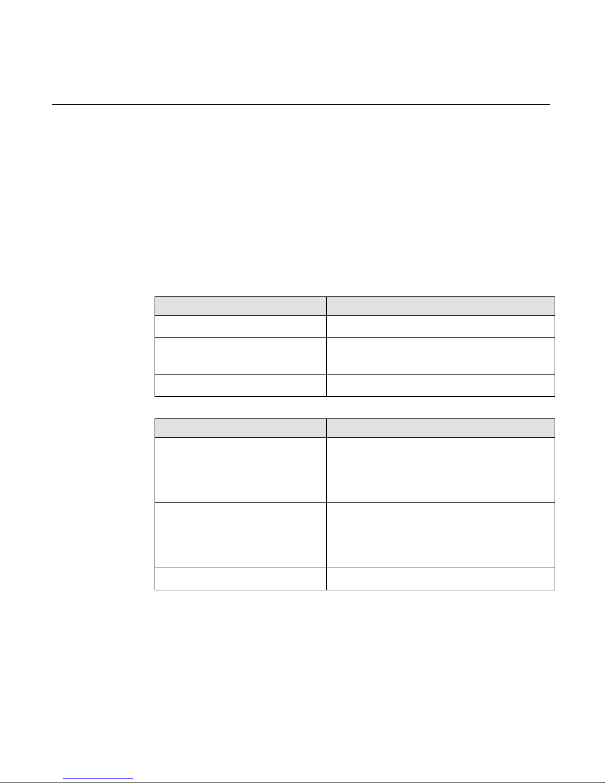
NCR Kit Numbers Description
5945-K010-V001 Cable: EIA-232 (9 Pin D Shell)
5945-K020-V001 Power Supply: (120V, 60Hz
US/Canada/Other)
5945-K021-V001 7452/7453 Power Adapter Cable
NCR Software Description
G370-1120-0100 Std 4430 Emulation Application
5945 Operating System
Loader Utility
G370-1121-0100 Publix 4430 Emulation Application
5945 Operating System
Loader Utility
B005-0000-1133 5945 Software Developers Kit
Page 16
2-4 Chapter 2: Installing the NCR 5945
16799
1
2
3
4
5
6
7
8
9
0
QZ
ABC
DEF
GHI
JKL
MNO
Yes
No
Cancel
Clear
Enter
PRS
TUV WXY
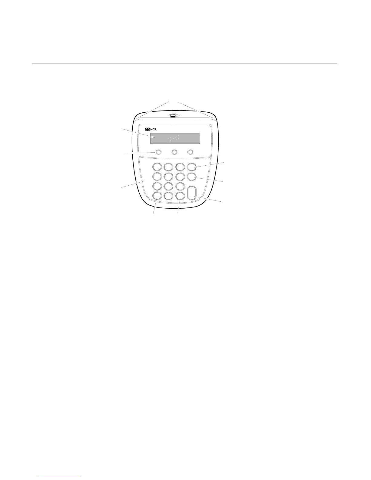
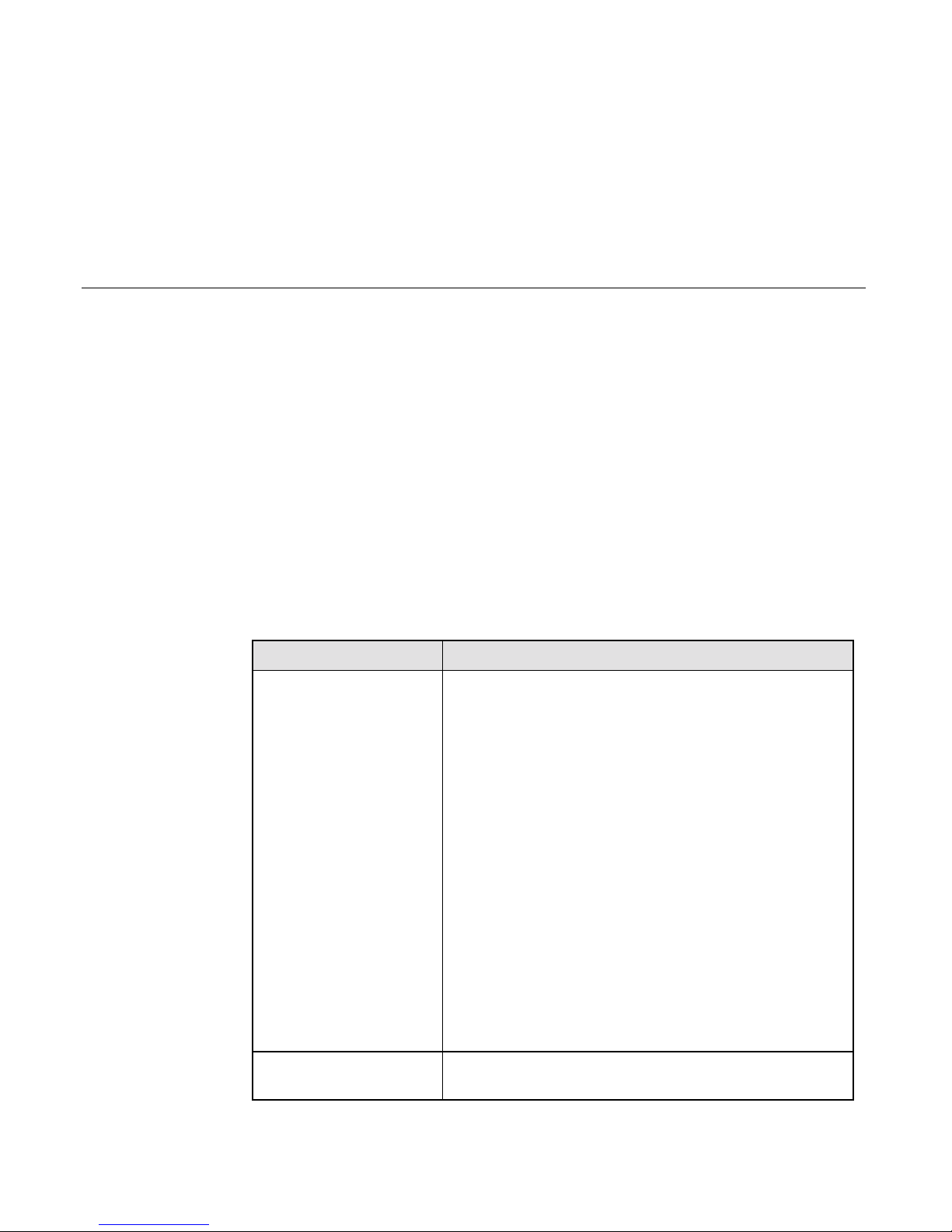
Reader Card
Display
Screen
screen
Addressable
Function
Keys (3)
Custom
Overlay
Yes Key
No Key
Enter
Key
Cancel Key
Clear Key
Card Reader
The track that the magnetic stripe card is
swiped through and read.
Display Screen
The display screen is used to display
messages and prompt customers for the next
action.
2x20 Screen
Addressable Function
Keys
These three function keys are used to choose
from up to three choices displayed on the
screen.
Yes and No Keys
These two keys are labeled as “Yes” and
“No” and can be used to answer a question.
Custom Overlay
The overlay can be customized to display
customer specific logos.
Cancel Key (Red)
Used to Cancel the current action.
Clear Key (Yellow)
Used to Clear the most recent character of a
customer entry (similar to a backspace key).
Enter Key (Green)
Used to submit a customer entry.
Page 17
Chapter 2: Installing the NCR 5945 2-5
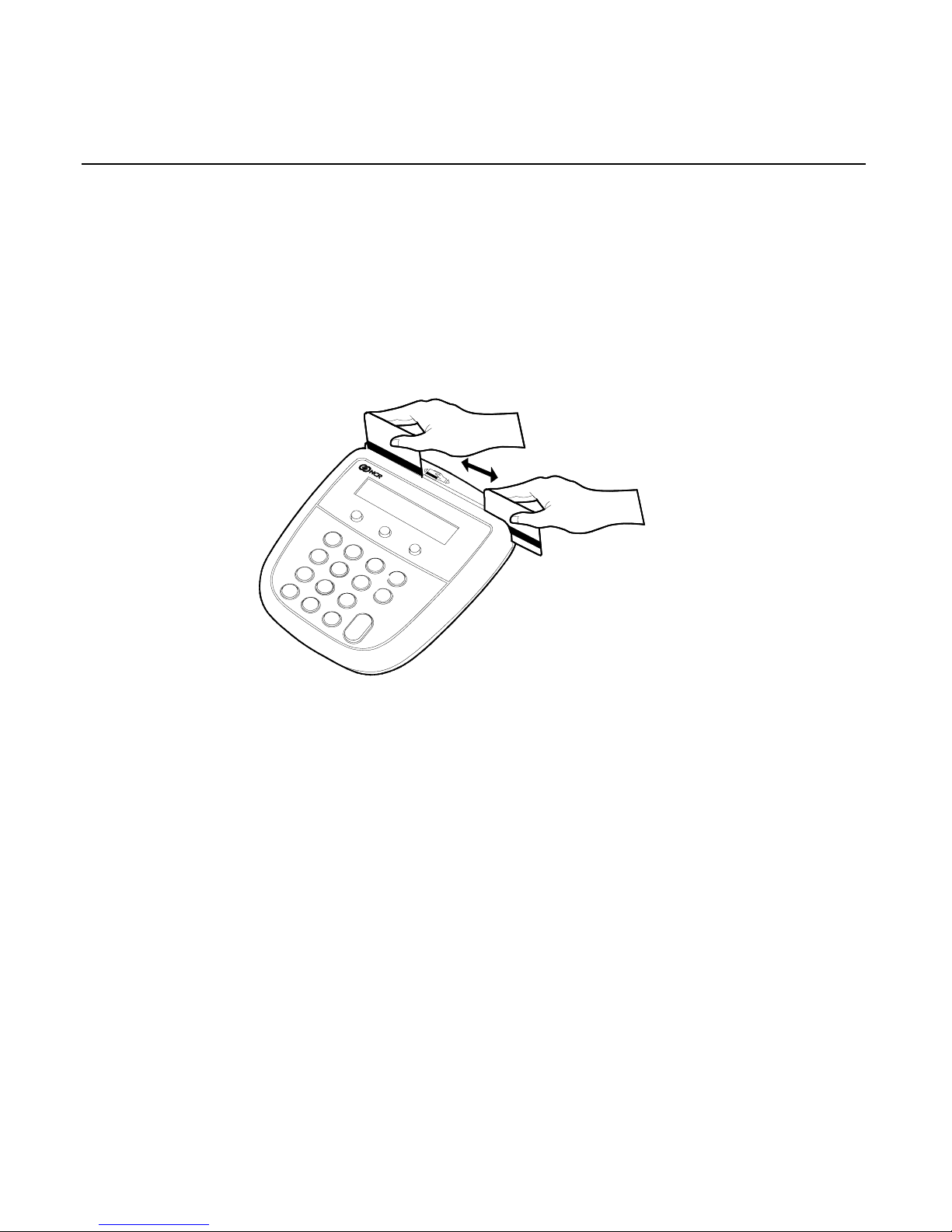
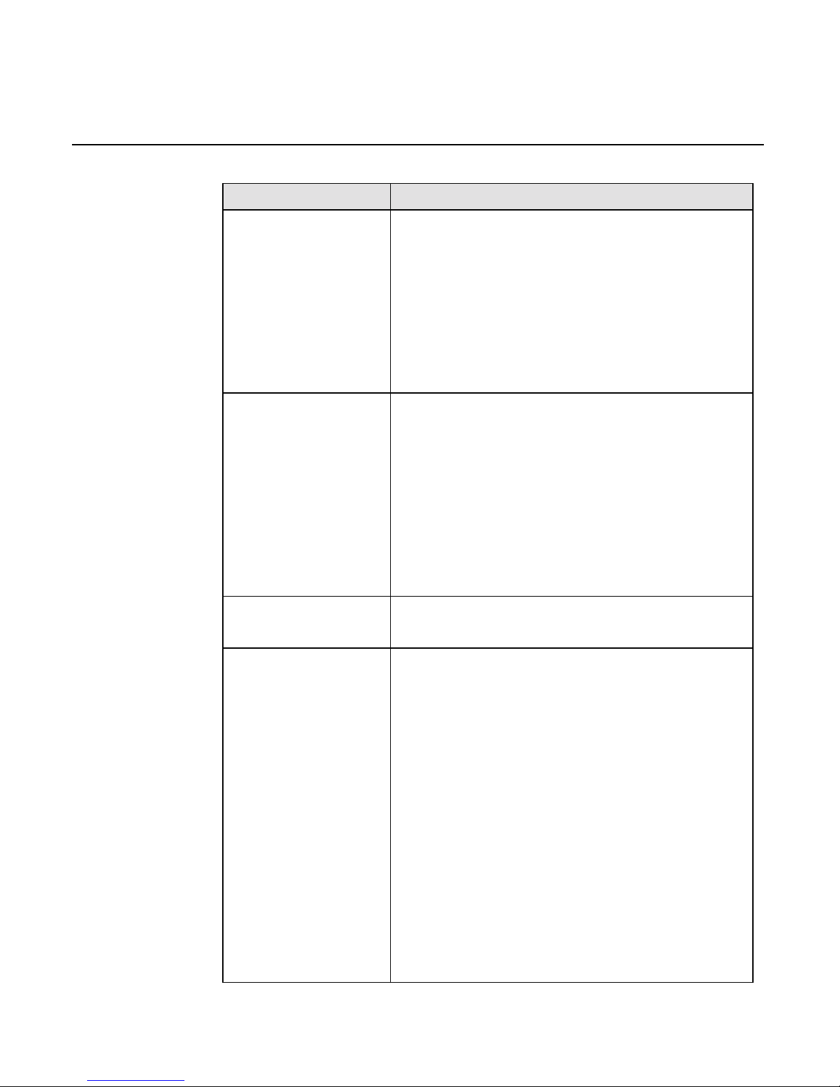
Sliding Cards through the Card Reader
The 5945 Card Reader reads debit, credit, and all standard magnetic
stripe cards. Be sure the magnetic stripe side of the card is facing the
5945 keypad. For best results, slide the card in a continuous motion.
You can slide the card in either direction (from left to right or right to
left).
16800
1
2
4
6
7
8
9
0
QZ
ABC
DEF
GHI
JKL
MNO
Yes
No
Cancel
Enter
PRS
TUV
WXY
3
5
Clear
Maintenance
There is no maintenance required for your NCR 5945. The outside case
can be cleaned with a damp
soft
cloth.
Note:
When cleaning the outside case, unplug the connector. DO
NOT use a harsh cleaning solution as it may damage the case. If a
cleaning solution is necessary, we recommend a whiteboard cleaner as
a safe agent, as long as the manufacturing safety instructions are
followed.
Outside Interference
Normal precautions for electrical and electronic equipment installation
should be observed, such as proper grounding and surge or overload
protection.
Cables and power cords should be secured to avoid accidental damage.
Page 18

2-6 Chapter 2: Installing the NCR 5945
Caution:
DO NOT place the NCR 5945 on a computer monitor or
adjacent to a power supply or other sources of high magnetic fields.
Specifications
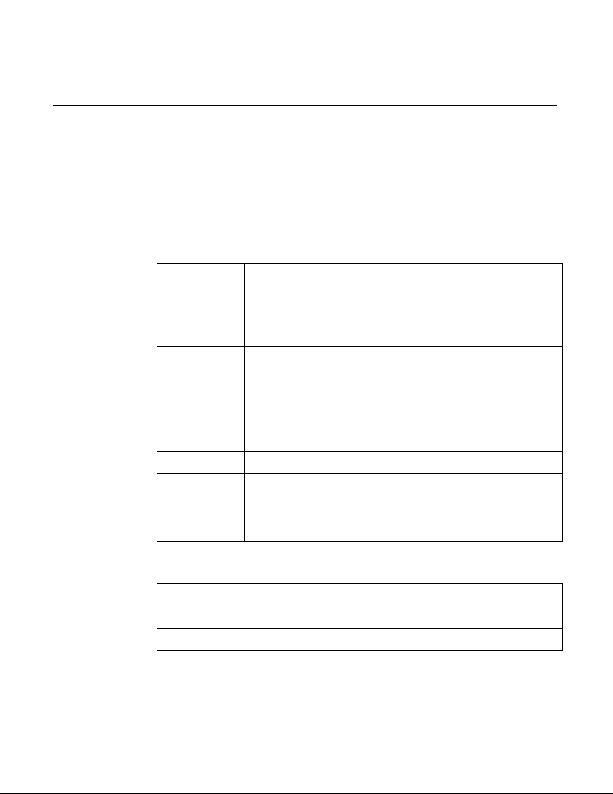
Operational Characteristics
Processor
Toshiba TMP95C061
Memory
512K of “flash” memory for application, parameter
and transaction storage.
32K static RAM for temporary data storage (stacks,
program data, etc.)
External Interfaces
Host Port EIA232)
AUX Port (EIA232 only) via Optional Remote
Connector Block can be used to multiplex 3 auxiliary
ports (A, B, C,) depending on the host port type.
One Additional EIA 232 port via optional “Y” cable.
Display
Backlit LCD with international character set support
and seven downloadable characters.
•
2 line by 20 character display
Beeper
Audio feedback (key press, alert, etc.)
Keypad
The keypad includes:
•
3 screen addressable function keys for the 2 x 20
character display unit
•
10 key numeric ISO compliant keypad
•
Yes and No function keys
•
1 green Enter key
•
1 red Cancel key
•
1 yellow Clear key
The use of the function keys depends on the 5945
application software installed on your unit.
Page 19
Chapter 2: Installing the NCR 5945 2-7
Compliance Listings
Safety: ETL Listed (To UL-1950, 3rd Edition
EMI: ETL (To CSA 22.2 #950)
FCC Part 15 Class A
European: CE Certified
Card Reader
Bi-directional, dual track (track 1 and 2), integrated
magnetic stripe reader. The card reader is designed to
read ABA format encoded tracks 1 and 2 (e.g., debit
card, credit card, driver’s license, etc.). Optional Track
3 capability is designed into the unit.
Internal PINpad
Logical and physical secure PIN entry is built into the
5945. The PINpad is DES capable, providing the ability
to perform both Master/Session and Derived Unique
Key Per Transaction (DUKPT) encryption.
Power
9 to 15 Volts DC. No external power supply is required
if power is available from the host device.
Current Rating
0.5 Amp,DC maximum.
Application
Programming
Applications can be developed using ANSI C. A base
application sample program and a set of application
programmer interface (API) routines are provided as
part of the 5945 developer’s kit.
Physical Interface
Size
6.5” wide x 6.0” length x 1.5” high (approximately)
Weight
.9 lbs. (approximately)
Coloring
Dark gray case, dark gray overlay, 4-color keypad
Page 20
2-8 Chapter 2: Installing the NCR 5945
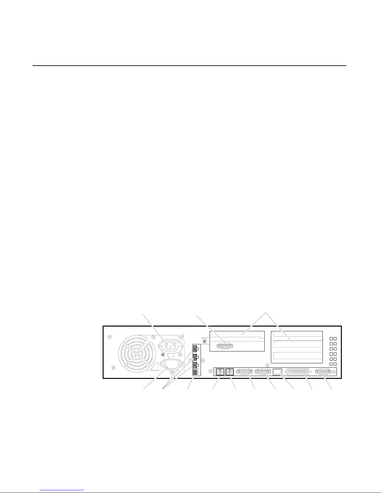
Connecting the NCR 5945 to the NCR
7452/7453/7454 Workstation
Migrating to the new 5945 Electronic Payment Terminal requires
minimal effort. The following illustrations show the steps needed to
connect the 5945 to an NCR 7452 or 7453 workstation. Connector
locations may vary slightly from model to model
Installation
Upon arrival, inspect all shipping containers for damage. If damaged,
open the box and verify that the 5945 Electronic Payment Terminal and
accessories have not been damaged. Report any damage to the
shipping carrier.
Find the appropriate cable configuration and power supply or power
supply cable adapter. (See Cable Configurations section of this
document.) Remove 5945 from shipping container and install either the
RS-232 Expander Cable or the RS-232 (9-Pin D Shell) to the 5945,
routing cable through the cable relief tray.
Save shipping containers for future use.
13258
CRT AC Power
Adapter Board Slots
AT
PCI
AT/PCI (Shared)
AT
Keyboard
AC Power Aux Power
(Printer)
Aux
Power
Mouse
RS-232
Port 1
Parallel
Port
VGARS-232
Port2
LAN
UPS Connector
Page 21
Chapter 2: Installing the NCR 5945 2-9
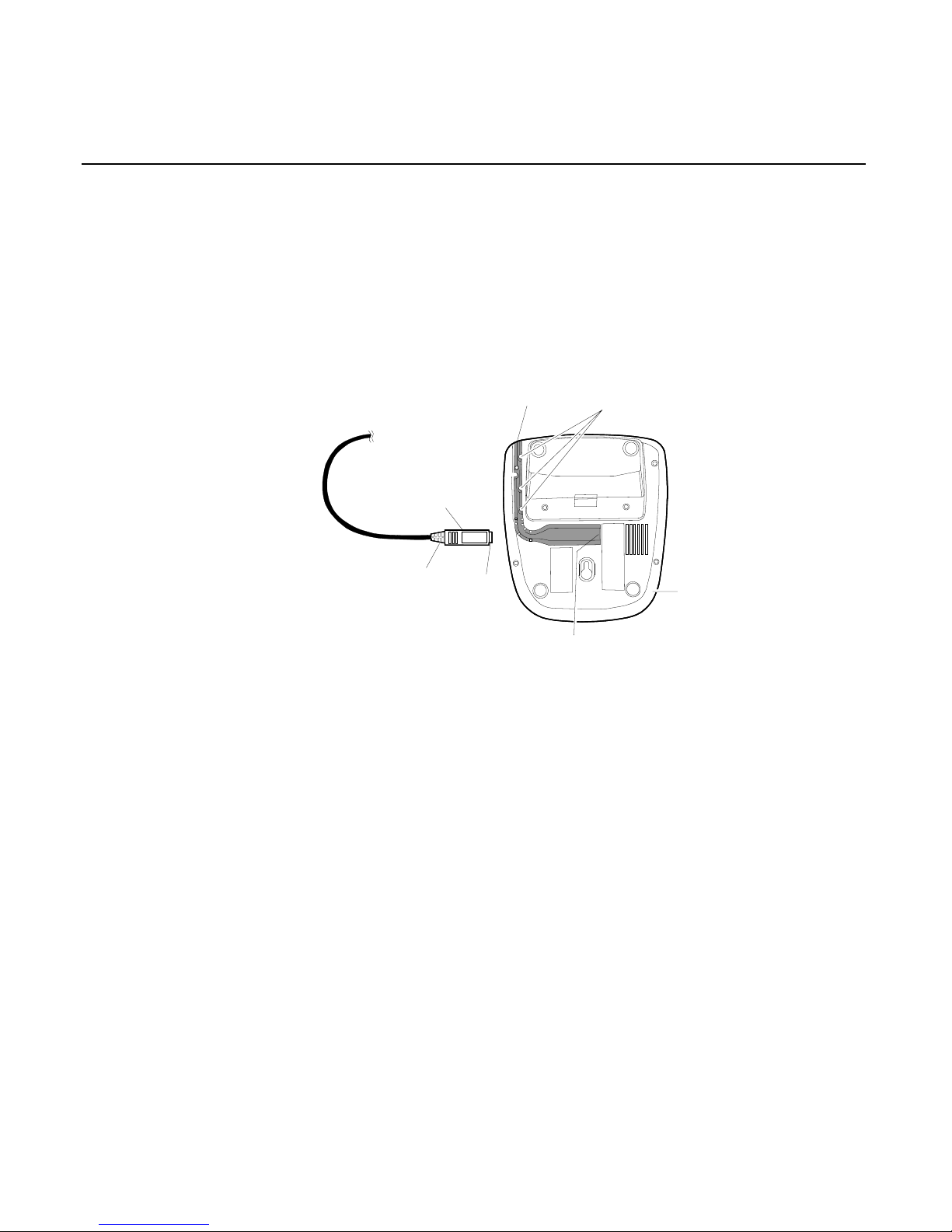
Connecting the 5945 Connector
This section provides step by step instructions on how to connect the
NCR 5945 connector.
1. Place the NCR 5945 in front of you with the bottom of the unit
facing up.
L Shaped
Cable Guide
Cable
Retension
Tabs
5945
Bottom View
5945 Port
Connector
Cover
(Flat side up)
Metal Pin
Cover
Hold
Here
16801
2. Hold the connector behind the cover, with the flat side of the
connector facing up.
3. Insert the connector into the port of the 5945.
4. With your thumb, push the connector into the 5945 port as far as it
will go to lock the cable in the port. All the metal pin cover of the
connector should be inside the port when it has been inserted far
enough.
Note:
IMPORTANT! You should be able to pull
gently
on the
cable without disconnecting it from the 5945.
Route the cable through the "L" shaped cable guide, and push the
cable down through the retention tabs to hold in place.
Page 22

2-10 Chapter 2: Installing the NCR 5945
Disconnecting the 5945 Connector
1. Gently pull the cable up from the "L" shaped cable guide retention
tabs.
2. Hold the connector behind the cover, and gently pull the connector
out of the 5945 port.
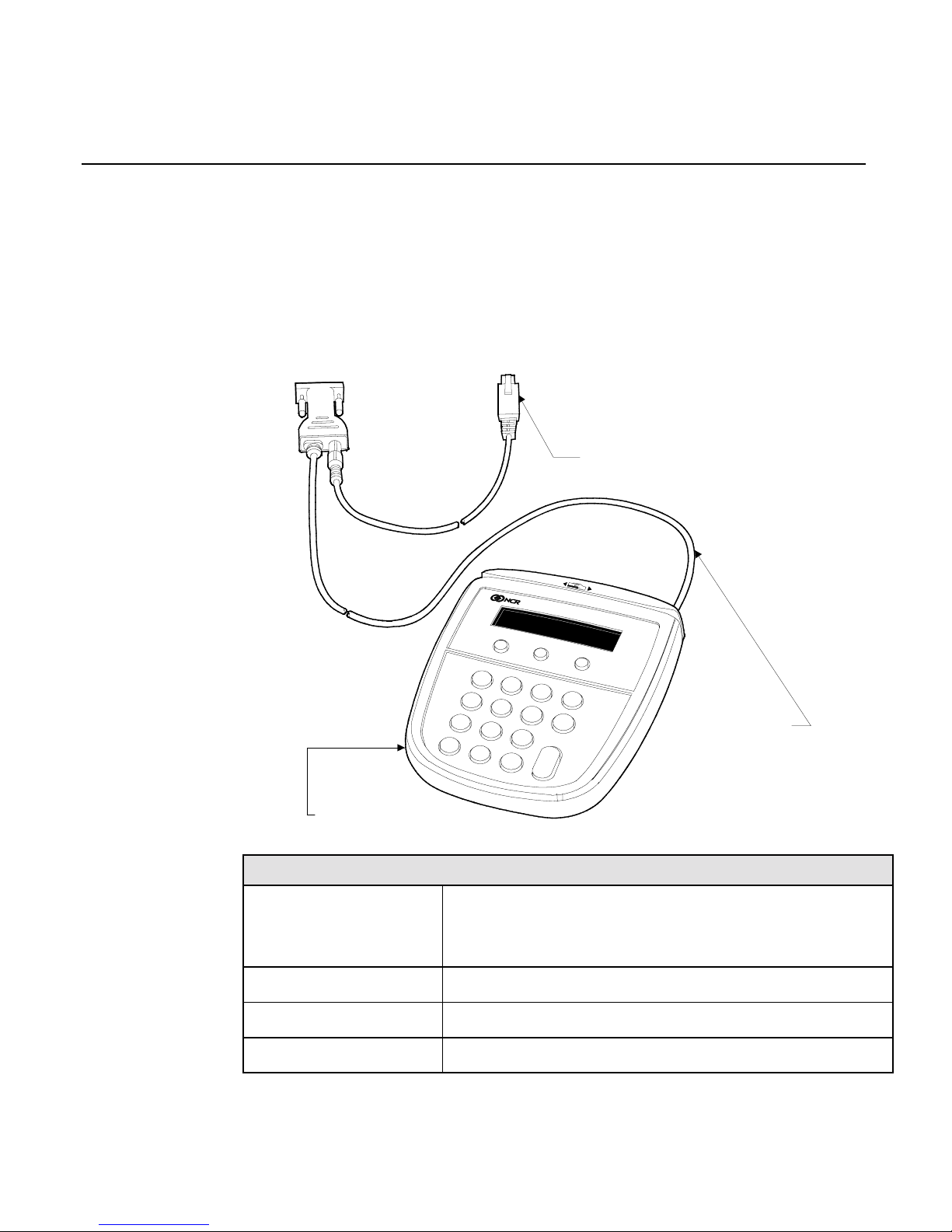
Connecting the 5945 with a Power Supply
The following illustration shows the steps needed to connect the 5945
to a host device, (PC or cash register) with a power supply.
1. Turn Off Power to your host device (PC or cash register).
2. Plug the 5945 Host Connector into the pre-determined port on
your host device.
3. Plug the 5945 Port Connector (MiniDIN 9) into the port on the
bottom of the 5945 unit, and route the cable through the L shaped
guide.
4. Plug the DC Power Supply into a standard wall outlet.
Warning:
Use only the DC Power Supply shipped with your unit.
Using any other power supply may damage the 5945
and will void the warranty.
5. Plug the Power Supply Connector into the Power Supply Jack on
the cable.
6. Once the 5945 has power and the PC or register is signed on, it is
ready for use as determined by your 5945 application software.
Page 23
Chapter 2: Installing the NCR 5945 2-11
Cable Configurations
The NCR 5945 Electronic Payment Terminal may be installed with the
following cable configurations or minor variations of the following.
See your NCR representative for help with your particular
configuration:
Configuration 1
16645
1
2
3
4
5
6
7
8
9
0
Clear
Cancel
Enter
No
Yes
QZ
ABC
DEF
PRS
JKL
MNO
GHI
TUV
WXY
7452/3 Power Adapter Cable
(5945-K021-V001)
RS-232 Cable
(9-Pin D Shell)
(5945-K010-V001)
5945 Electronic Payment Terminal
(5945-K100-V001)
To RS-232 port
of workstation
Configuration 1: 5945 connected to 7452/7453.
5945-K100-V001
5945-K150-V001
Electronic Payment Terminal W/Security and
512KB Memory, Track 1,2 MSR, 2x20 Display,
5944 & 4430 Emulation
5945-K010-V001 Cable: RS-232 (9-Pin D Shell)
5945-K021-V001 7452/3 Power Adapter Cable
5945-K030-V001 Keyboard Overlay - Generic
Page 24
2-12 Chapter 2: Installing the NCR 5945
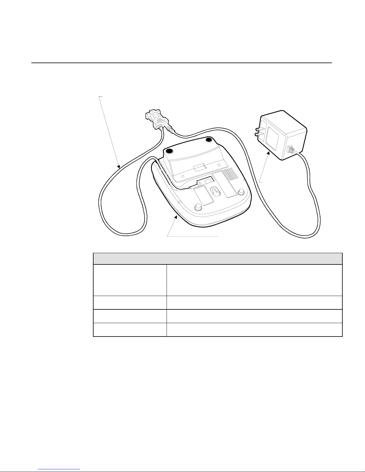
Configuration 2
16644
Bottom View of 5945
Electronic Payment Terminal
(5945-K100-V001)
Power Supply
(5945-K020-V001)
To RS-232 port
of Workstation
RS-232 Cable (9-Pin D Shell)
(5945-K010-V001)
Configuration 2: 5945 connected to 7452/3 using 120 VAC power.
5945-K100-V001
5945-K150-V001
Electronic Payment Terminal W/Security and
512KB Memory, Track 1,2 MSR, 2x20 Display, 5944
& 4430 Emulation
5945-K010-V001 Cable: RS-232 (9-Pin D Shell)
5945-K020-V001 Power Supply: (120V, 60Hz US/Canada/Other)
5945-K030-V001 Keyboard Overlay - Generic
Page 25
Chapter 3: Troubleshooting the NCR 5945
In the event your NCR 5945 is not working properly, you should first
consult the following troubleshooting table. Find the problem you are
experiencing in the
Problem
column, perform (in sequence) each of the
actions in the
Solution
column.
Note:
If all solutions have been tried and you are still experiencing
problems, contact your
NCR Help Desk
to arrange to return the unit for
repair.
NCR 5945 Troubleshooting Table
PROBLEM SOLUTION
The Magnetic Strip
Reader does not
seem to work
properly.
Make sure that the magnetic stripe on the
card is facing the NCR 5945 key pad when
sliding the card through the reader.
Swipe the card at a faster or slower
steady
speed.
Swipe the card in the reverse direction (i.e., if
swiping the card from right to left, try
swiping from left to right).
Inspect the magnetic stripe on the card,
making sure it is not scratched or badly
worn.
If you have another working 5945 unit, try
reading the card on that unit to determine if
the problem is with the unit or with the card.
The Magnetic Strip
Reader does not
With the cleaning surface facing the display,
clean MSR with card part number
Page 26
3-2 Chapter 3: Troubleshooting the NCR 5945
PROBLEM SOLUTION
seem to work
properly.
603-9004998
Try reading card again, if 5945 MSR fails,
(cont)
Return unit for service.
Note:
Clean heads on other 5945 units at this
time since the cleaning card should not be
used at a later time
The 5945 display is
not working.
Make sure the 5945 Connector (MiniDIN 9) is
fully inserted into the back of the unit.
Unplug the unit and plug it back in.
If you have another working 5945 unit, swap
the units to determine if the problem is with
the unit or with the cable or register.
If you do not have a power supply, reset the
register by turning it off and back on again.
Display is blank
with a glow
Reload Operating System or application. If
5945 does not work, return 5945 for service.
5945 does not
operate
Ensure power cord is connected to unit
Wrong Power Brick—Power Brick (if used)
should be labeled: 5945-K020-V001
Check power connection to the
Communication Cable
Check Communication Cable connection
5945
Defective Communication Cable or Defective
Host Terminal.
If another host terminal is available:
Move the 5945 to a known working
terminal.
Move Communications Cable from
Page 27

Chapter 3: Troubleshooting the NCR 5945 3-3
PROBLEM SOLUTION
original host to known working host
terminal and attach 5945.
If 5945 does not work, return unit for
repair.
If 5945 works, original host unit
requires service. If 5945 does not
work, Communications Cable is
defective.
Error detected during Start-Up diagnostics.
Call NCR help desk or NCR representative
and arrange for to return unit for repair.
Page 28

Page 29

Chapter 4: Using the Supervisor Mode
The NCR 5945 supervisor mode allows authorized personnel to
execute various functions from a menu on the NCR 5945, using the
keypad.
The supervisor mode functions are:
•
Modifying parameters.
•
Downloading a program and or parameters from a PC.
•
Obtaining version information on the NCR 5945.
•
Re-initializing the NCR 5945.
Starting
To initiate the supervisor mode: press and hold the top-left (Function
key #1) and the bottom right (Enter key) at the same time.
Note:
Keys must be pressed during booting and before application
begins.
16804
1
2
3
4
5
6
7
8
9
0
QZ
ABC
DEF
GHI
JKL
MNO
Yes
No
Cancel
Clear
Enter
PRS
TUV WXY
Enter
Key
Function
Key #1
2x20 Display Screen
Page 30

4-2 Chapter 4: Using the Supervisor Mode
Password
The NCR 5945 will display the following prompt:
Enter Password:
If the password is correct, the Supervisor Main Menu will display. For
detailed descriptions of each menu item, refer to the “
Main Menu
Items
” section discussed later in this chapter. If the password is
incorrect, supervisor mode is not initiated and the application will
start. The Supervisor menu items can be stepped through using
function keys 5 (Yes) and 6 (No).
Default Password
The default password for the NCR 5945 as shipped from the factory is:
263 (CME)
1. At the “Enter Menu Password” prompt, type: “263”, and press
Enter.
Changing the Password
The default password can be changed as follows:
1. Select
Change Password
from the Main Menu, and press Enter.
2. Type the new password at the “Enter New PW:” Menu, and press
Enter.
3. Type the new password again (to confirm) at the “Verify New PW”
Menu, and press Enter.
The new password will be written to memory.
Page 31

Chapter 4: Using the Supervisor Mode 4-3
Operation
Selecting Commands
16805
1
2
3
4
5
6
7
8
9
0
QZ
ABC
DEF
GHI
JKL
MNO
Yes
No
Cancel
Clear
Enter
PRS
TUV
WXY
Enter
Key
Cancel Key
2x20 Display Screen
Function
Key #5
Function
Key #6
Clear Key
Function keys 5 (Yes) and 6 (No) are used to scroll (up and down)
through the different menu items on the Main Menu. These menu
items will be described later in this chapter.
When the desired menu item displays on the NCR 5945, press Enter.
Note:
The Cancel key can be used at any time to abort the command
and return to the Main Menu.
When prompted for information, you use the numeric keypad to enter
data. The Clear key will remove the last character entered. Pressing
Enter when completed will end the action.
Page 32

4-4 Chapter 4: Using the Supervisor Mode
Entering Alphanumeric Data
This section describes how to enter alphanumeric and binary data.
16806
1
2
3
4
5
6
7
8
9
0
QZ
ABC
DEF
GHI
JKL
MNO
Yes
No
Cancel
Clear
Enter
PRS
TUV WXY
Enter
Key
2x20 Display Screen
Binery
Key
Alpha
1 Key
Alpha
2 Key
Alpha
3 Key
Alphanumeric and binary data (all characters in the range of 0 to 255)
can be entered from the NCR 5945 keypad at the File Write “Enter
Data:” prompt.
The Alpha keys specify the position of the alpha character you want to
enter, on the number key. To enter an alphanumeric character, press
the appropriate Alpha 1, 2 or 3 key followed by the number key that
contains the alpha character.
For example, if you wanted to enter the alphanumeric characters
“AKV”, you would press the following key sequences:
1. To enter the character “A”, press the Alpha 1 key (since “A” is in
position 1 of the number key) followed by the “2” key.
2. To enter the character “K”, press the Alpha 2 key (since “K” is in
position 2 of the number key) followed by the “5” key.
3. To enter the character “V”, press the Alpha 3 key (since “V” is in
position 3 of the number key) followed by the “8” key.
Page 33

Chapter 4: Using the Supervisor Mode 4-5
To enter a space character, press any Alpha key followed by the “0”
key.
To enter a character that is not available on the keypad, press the
Binary key and type the 2-digit hexadecimal number for the desired
character. The NCR 5945 is configured with standard ASCII binary
hexadecimal nu mb er s.
Main Menu Items
CMDL
The CMDL Menu is the first menu item that appears when the Main
Menu displays.
CMDL is used for downloading a program or parameters from a PC.
Download the application to the 5945 using the NCRCMDL.exe utility.
NCRCMDL.EXE is included in the 5945 Software Developers Kit which
is available as part of the 5945 Developers Guide and separately. The
back slashes (\) are necessary to escape the double quotes (“) in DOS.
EX: NCRCMDL download 1 \”file.bin\”;
To generate a form of the application which can be downloaded using
the 5944LD.exe application follow these additional steps.
Generate EFTL & EFTP files by using the NCRCMDL.exe utility. For a
complete description refer to the 5945 Developer’s Guide. The back
slashes (\) are necessary to escape the double quotes (“) in DOS. Note
that the program and parameter levels of the 5945 resident application
and file system are taken from the four digit suffix of the EFTL and
EFTP files respectively.
EX: NCRCMDL do \”eft.cmc\”;
EX: Contents of eft.cmc
{
print "Creating EFT Program File";
ibmeft247 file "eftl0001.";
download 0 "file.bin";
ibmeft247 file close;
print "Creating EFT Parameter File";
ibmeftbin247 32 0001 file "eftp0001.";
Page 34

4-6 Chapter 4: Using the Supervisor Mode
msglevel 0;
/* The next line is necessary to enable 5944 downloads */
write system app 15 32769 record 4 “1”;
do "param.cmc";
msglevel 2;
ibmeftbin247 32 0001 file close;
print "Done!";
}
EX: Contents of param.cmc
{
/* Notice that within a cmc file processed by NCRCMDL no
backslash is necessary to escape the double quotes */
write public app 1 2 record 3 “This is an example file entry”;
write public app 1 2 record 4 “Record 3 & 4 of file 2 are data
strings”;
}
*The program and parameter levels are stored in the file system:
write system app 15 32770 record 10 “0001”; /* program level */
write system app 15 32770 record 11 “0001”; /* parameter level
*/
Now convert the EFT files to a 5944 style download file by using the
CEFT2NCR.exe utility. This utility is included in the 5945 Software
Developer’s Kit which is available as part of the 5945 Developer’s
Guide and separately. This will generate a file called download.out
that can be downloaded as described in the next section. The
5944ld.exe utility can be used to download this file to the 5945.
EX: ceft2ncr eftp0001 eftl0001
Press the Cancel key to abort the download and return to the Main
Menu.
Start App
Start App
is used to start the application, by pressing Enter. If an
application program is not loaded for the unit, an “Invalid Ap p 1”
message displays and the NCR 5945 will try to download a program
from the host.
Page 35

Chapter 4: Using the Supervisor Mode 4-7
File Sys
Selecting
File Sys
will display various other menu levels. These
commands allow viewing and modification of certain parameters.
With the current release of 5945, these parameters should not be
modified.
ID Banner
Selecting
ID Banner
will display the current version level of the NCR
5945 software. Press Enter to return to the Main Menu.
Serial Number
Selecting
Serial Number
will display the serial Number NCR 5945 .
Press Enter to return to the Main Menu.
Change Password
This option allows the user to change the password required to initiate
the supervisor mode.
Note:
For detailed information on this option, refer to the “
Changing
the Password
” section discussed earlier in this chapter.
Page 36

Page 37

Chapter 5: NCR 5945 Diagnostics Specification
This document describes the diagnostic routines in the NCR 5945. The
purpose of the diagnostics is to isolate failures in field installed NCR
5945's. The diagnostics are part of the operating system and are
uniform across all applications. The diagnostics are menu driven with
features that allow a logical progression through the individual tests.
Startup Sequence
The Diagnostics Mode is built into the Operating System of the NCR
5945. To access the Diagnostics Mode, press and hold down the top
Function “2” key and the "Enter" key at the same time.
16802
1
2
3
4
5
6
7
8
9
0
QZ
ABC
DEF
GHI
JKL
MNO
Yes
No
Cancel
Clear
Enter
PRS
TUV WXY
Function
Key #2
Enter
Key
2x20 Display Screen
After these keys are pressed and released, the Enter password prompt
displays. Type in the password “3424” (“DIAG”), and press Enter. If
the correct password is not entered, the application is restarted.
Page 38

5-2 Chapter 5: NCR 5945 Diagnostics Specification
Operation
Navigating through the Menu Items
16803
1
2
3
4
5
6
7
8
9
0
QZ
ABC
DEF
GHI
JKL
MNO
Yes
No
Cancel
Clear
Enter
PRS
TUV
WXY
Function
Key #5
Enter
Key
Function
Key #6
Cancel Key Clear Key
2x20 Display Screen
NCR 5945 Keys
Key Description
Function key #5 Used to scroll to the previous item in the
menu list.
Function key #6 Used to scroll to the next item in the menu list.
Enter key Used to initiate the currently displayed menu
item.
Cancel key Used to back out of a menu, or end an
executing test.
Page 39

Chapter 5: NCR 5945 Diagnostics Specification 5-3
Menu Flow
The NCR 5945 diagnostics menu allows for 13 individual tests to be
performed. These tests display in the following sequence:
1. Keypad Test: Verifies that each key on the keypad is functioning
properly.
2. Display Test: Tests the NCR 5945 display screen checking that each
pixel is in working order.
3. MSR Test: The MSR diagnostics test the NCR 5945 Magnetic Stripe
Reader, checking that both track 1 and track 2, and track 3 (if
installed), is reading properly.
4. IBM 46xx Test: Reports whether of not the NCR 5945 is receiving
RS485 IBM 4680 Feature C polls at the indicated address.
5. Host RS232 Test: Sets the NCR 5945 Baud Rate, Parity, Data bits,
Port Type, and tests the host communication port.
6. AUX1A RS232 Test: Sets the NCR 5945 Baud Rate, Parity, Data
Bits, and tests the AUX1A communication port.
7. AUX 1B RS232 Test: Sets the NCR 5945 Baud Rate, Parity, Data
Bits, and tests the AUX1B communication port.
8. SRAM Test: Runs a functional test on the RAM chip.
9. Encryption Test: Performs a Test Encrypt for DUKPT, and
extended for Master/Session with an internally defined account
number and PIN as defined in Visa document
“Point of Sale
Equipment Requirements”,
PIN Processing and Data Authentication,
International Version 1.0 August 1988
10. Key Check Value: Allows confirmation of injected PIN encryption
keys.
11. OS Version: Displays the installed OS software version number.
12. Library Version: Displays the software library version number
that was used to generate the application.
13. Security Version: Displays the installed software security module
version number.
Page 40

5-4 Chapter 5: NCR 5945 Diagnostics Specification
After the correct password is entered, the display changes to:
First line: DIAGNOSTICS
Second line: Keypad Test
Function keys #5 and #6 navigate up and down through the menu
items.
Press Enter to execute the Keypad Test, or press Function key #5 to
display the next test on the menu (Display Test). Pressing the Cancel
key exits the Diagnostics Menu and starts the application.
Keypad Test
The keypad diagnostics tests that each key on the NCR 5945 keypad
functions. Select the Keypad Test from the DIAGNOSTICS Main
Menu:
First line: Keyboard Test
Second line: Key in sequence
Each key on the keypad must be pressed in the defined sequence and
within 30 seconds. Begin test by pressing the keys starting at the top
left corner of the keypad, moving left to right and downward until all
keys have been pressed.
If all key presses are detected properly, the following message
displays:
First line: Test passed
Second line: Press any key...
If the exact key sequence is not pressed within the allotted 30 seconds,
the following message displays:
First line: Test failed
Second line: Press any key...
Pressing any key on the keypad returns the KEYPAD TEST menu.
Press Function keys #5 and #6 to navigate through the available
diagnostic test menus, or press Cancel to exit the session and restart
the NCR 5945 application.
Page 41

Chapter 5: NCR 5945 Diagnostics Specification 5-5
Display Test
The display diagnostics test the NCR 5945 display screen checking that
each pixel is in working order. Select the Display Test from the
DIAGNOSTICS Main Menu:
First line: DISPLAY TEST
Second line: Press any key...
Press a key to step through the following sequence. Verify that no
pixels are stuck on or off.
1. All pixels on.
2. Every other pixel off.
3. All pixels off.
4. Every other pixel on.
Once the last screen has displayed, the following prompt displays:
First line: Test Passed?
Second line: Yes
“Yes” displays, press Enter to return to the DISPLAY TEST Main
Menu.
Note:
Function key #5 can be used to display a Yes answer, or
Function key #6 can be used to display a No answer. The Enter key
accepts the displayed Yes or No answer.
Once Enter is pressed and the DISPLAY TEST Main Menu displays,
press Function keys #5 and #6 to navigate through the available
diagnostic test menus, or press Cancel to exit the session and restart
the NCR 5945 application.
MSR Test
The MSR diagnostics test the NCR 5945 Magnetic Stripe Reader. A
valid magnetic stripe card, preferably one with valid data on tracks 1,
2,and 3, must be available to perform this test. Most any Visa or
AMEX card should work. Select the MSR Function key from the
DIAGNOSTICS Main Menu.
First line: MSR TEST
Second line: Swipe card...
Page 42

5-6 Chapter 5: NCR 5945 Diagnostics Specification
Swipe a valid MSR card with the magnetic stripe facing the keypad.
After the first card is slid, the display changes to:
First line: T1= 001 T2= 001
Second line: T3= 000 TOT=001
T1 through T3 (track 1, 2 and 3) accumulates and displays the number
of times a card was successfully swiped and read correctly for that
track. TOT keeps a running tally of how many card swipes have been
performed. If an error is detected for a track, the error code displays.
The following table shows the error codes and their associated
description.
Error Code Description
NoSS No Start Sentinel character
NoES No End Sentinel character
LRCE Longitudinal Redundancy Check Error
ParE Parity Error
NoFS No Field Separator
PrsE Parse Error
???? Unknown card type for track
Example; the following screen shows 5 good reads for track 1, a parse
error on track 2 data, track 3 not installed, and a total of 5 card swipes.
First line: T1= 005 T2= PrsE
Second line: T3= 000 TOT=005
The test ends after the number of card swipes specified in the
parameter list, or if the Cancel key is pressed during the test.
Once the MSR TEST Main Menu displays, function keys #5 and #6 can
be used to navigate through the available diagnostic test menus, or
press Cancel to exit the session and restart the NCR 5945 application.
Page 43

Chapter 5: NCR 5945 Diagnostics Specification 5-7
IBM 46xx Test
Reports whether or not the NCR 5945 is receiving RS485 IBM 4680
Feature C polls at the indicated address.
Select the IBM 46xx TEST from the Diagnostics Menu:
IBM 46xx TEST
2A23 <0x68>
The second line displays the first slot and port number option that can
be tested.
The keypads Yes and No keys are used to scroll up and down through
the 4 available slots and port number options. These 4 options are:
1. 2A23 <0x68>. Selects slot 2A, port 23. This corresponds to the
Feature C address 0x68 (104).
2. 2A25<0x64>. Selects slot 2A, port 25. This corresponds to the
Feature C address 0x64 (100).
3. 2B23<0x69>. Selects slot 2B, port 23. This corresponds to the
Feature C address 0x69 (105).
4. 2B25<0x65>. Selects slot 2B, port 25. This corresponds to the
Feature C address 0x65 (101).
To test the Feature C port, select the port by pressing the Enter key
when the appropriate slot and port option displays. The following
information displays:
Testing 2A23
Poll Count 0000
The first line displays the slot and port option selected.
The Poll Count on line two displays the number of Polls that have been
received at this port address. Polling always starts from zero.
If the selected Feature C port is active on the IBM 46xx, the number of
polls increment at a rapid rate. This indicates that communications
with the IBM 46xx register are being conducted.
Page 44

5-8 Chapter 5: NCR 5945 Diagnostics Specification
Pressing the Cancel key during this test returns the IBM 46xx Test
screen. The keypad Yes and No keys are used to navigate through the
available diagnostic test menus, or press Cancel to exit the session and
restart the NCR 5945 application.
Page 45

Chapter 5: NCR 5945 Diagnostics Specification 5-9
Host RS232 Test/ AUX 1A RS232 Test/ AUX 1B RS232 Test
The Host RS232 diagnostics sets the NCR 5945 Baud Rate, Parity, Data
Bits, Port Type, and tests the communication port hardware.
Select HOST RS232/ AUX 1A RS232 Test/ AUX 1B RS232 Test from
the DIAGNOSTICS Main Menu. The following Communications
Menu displays allowing for a series of selections associated with this
test.
First line: Host 19200,N,8
Second line: Baud rate
The default parameters display on the first line. The second line
displays the baud rate selection. Function keys #5 and #6 are used to
scroll up and down through the 4 second line selections. The available
selections are:
•
Baud Rate Allows a different Baud Rate to be selected.
•
Parity Allows a different Parity to be selected.
•
Data Bits Allows a different Data Bit to be selected.
•
Test Allows a port test to be performed for the parameters
selected
•
Port Type Allows a different communication type to be selected.
The Enter key is used to execute the displayed selection screen for
parameter entry.
Page 46

5-10 Chapter 5: NCR 5945 Diagnostics Specification
Baud Rate Selection
Select Baud rate from the selection screen. The display changes to:
First line: Baud Rate
Second line: 19200
The default baud rate of "19200" displays. Function keys #5 and #6 are
used to scroll through the available options. The available baud rate
options are:
•
19200
•
9600
•
4800
•
2400
•
1200
When the desired option displays, press the Enter key to accept that
parameter.
Pressing the Cancel key during this test returns the Host RS232 Test
Menu. Pressing Cancel again returns the DIAGNOSTICS Main Menu.
Parity Selection
Select Parity from the Host RS232 Test Menu
First line: Parity
Second line: None
The default parity of "None" displays. Function keys #5 and #6 are
used to scroll through the available options. The available parity
options are:
•
None
•
Odd
•
Even
When the desired option displays, press the Enter key to accept that
parameter.
Pressing the Cancel key during this test returns the Host RS232 Test
Menu. Pressing Cancel again returns the DIAGNOSTICS Main Menu.
Page 47

Chapter 5: NCR 5945 Diagnostics Specification 5-11
Data Bit Selection
Select Data Bits from the Host RS232 Test Menu
First line: Data Bits
Second line: 8
The default baud rate of "8" displays. Function keys #5 and #6 are used
to scroll through the available options. The available data bit options
are:
•
7
•
8
•
9
When the desired option displays, press the Enter key to accept that
parameter.
Pressing the Cancel key during this test returns the Host RS232 Test
Menu. Pressing Cancel again returns the DIAGNOSTICS Main Menu.
Port Type
Select Port Type from the HOST screen.
Port Type
RS 232
The default type “RS232” displays. The keypad Yes and No keys are
used to scroll through the available options. The available port type
options are:
•
RS 232
•
RS 485
When the desired option displays, press the Enter key to accept that
parameter.
Pressing the Cancel key during this test returns the HOST screen.
Pressing Cancel again returns the Host RS232 Test screen.
Page 48

5-12 Chapter 5: NCR 5945 Diagnostics Specification
Test Selection
Select Test from the Host RS232 Test Menu
First line: Test 19200,N,8
Second line: 123
The host port should be connected to the PC using the port-to-PC test
cable (AC00446 or equivalent) that came with your NCR 5945. Any
terminal program (such as Procomm Plus® or the terminal program
from Windows) can be used for this test. The RS232 parameters of this
program must be set to the same RS232 parameters specified for the
host port test. The port the NCR 5945 is connected to should be
selected on the PC.
Note:
To change the communication parameters, press Cancel to
return to the HOST screen. The keypad Yes and No keys are used
to scroll through the available options. Refer to the following Baud
Rate, Parity, and Data Bit selections for detailed information on
changing the communication parameters. Once the parameters
have been set, select TEST from the HOST screen and retest.
Press any key on the NCR 5945 keypad (except the Cancel key). That
character is transmitted over the RS232 host port and received and
displayed on the PC. The character will not be displayed on the NCR
5945.
If a key is pressed on the PC keyboard, that character is received on the
NCR 5945 and displays on the second line of the unit. If the second
line becomes full, the next key pressed clears the line and displays
starting at the beginning of the line.
Pressing the Cancel key during this test returns the HOST screen.
Pressing Cancel again returns the Diagnostics Host RS232 Test screen.
When selecting the RS485 test, the cable configuration is different. The
PC must connect to an AC03008 which is connected to an RCB 67/RCB
29. The RCB is connected to the unit through an AC (?). The PE00732
power supply will connect into the RCB 67/29.
Page 49

Chapter 5: NCR 5945 Diagnostics Specification 5-13
SRAM Test
The SRAM diagnostics test the read and write capabilities on the RAM
chip. Select SRAM TEST from the DIAGNOSTICS menu. The test is
conducted and results are displayed. For example:
032k Passed
Press any key . . .
Pressing any key exits this screen and returns the DIAGNOSTICS
menu. Pressing the Cancel key exits the session and starts the NCR
5945 application.
Page 50

5-14 Chapter 5: NCR 5945 Diagnostics Specification
Encryption Test
The encryption diagnostics test the security module with an internally
defined account number and PIN. The output of this function can be
used to verify that the correct key has been injected at the designated
index. The test may be done in either Master Session or DUKPT mode.
Select ENCRYPTION TEST from the DIAGNOSTICS menu.
ENCRYPTION TEST
Master / Session
The Master / Session mode displays. Press the Yes and No keys to
toggle between the Master / Session and DUKPT modes. Press Enter
to select and test the displayed mode.
The Encryption Test allows cryptographic confirmation of injected PIN
encryption keys; generates and displays an encrypted PIN block from a
known PIN and account number as defined by VISA documentation.
Note:
Test Encrypt will work with Master/Session keys as well.
If Master / Session is selected, the NCR 5945 performs the encryption
and displays the 16 characters generated. This indicates the encrypted
PIN block. The numbers generated will be the same for each NCR 5945
with the same Master/Session keys.
Press any key to return to the Test Encrypt menu.
If DUKPT is selected, the NCR 5945 performs the encryption and
displays 2 lines. The first line of 16 Characters represents the
encrypted PIN block. The second line of 20 characters represents the
KSN (Key Serial Number)
Press any key to return to the Test Encrypt menu.
Note:
The NCR 5945 must have had a key injected in order for
this test to perform correctly.
Note:
Test encrypt works by building an ANSI PIN block with
a known account number and PIN as defined in the VISA
document
“Point-of-Sale Equipment Requirements”
, PIN
Processing and Data Authentication, International Version 1.0,
August, 1988.
Page 51

Chapter 5: NCR 5945 Diagnostics Specification 5-15
Key Check Value
Used to verify that the correct keys are injected into the appropriate
index. The key check value is defined as the first six characters of the
encrypted result obtained by encrypting known data (all zeros) with
the designated key.
Menu Option Description
DIAGNOSTICS
Key Check Value
Pressing Enter will select the
displayed menu option.
Note:
Press Yes or No to move
forward or backward through the
menu options.
Selecting this option, the user is prompted for
index. Valid indices are 0-9 f or
Master/Session and 0-3 for DUKPT.
Note:
The displayed result does not
reveal any information about the key
that has been injected but allows the
user enough information to verify with
a high degree of probability that the
correct key has been injected.
Note:
The NCR 5945 stores all master
keys as double length keys
Key Check Value
Master 1st Part
Displays the key check value for the first
part of double length master key.
Key Check Value
Master 2nd Part
Displays key check value for the second
part of double length master key.
Key Check Value
Master Double
Displays the key check value for the
entire double length master key.
Key Check Value
Session
Displays the key check value for the
session key of a Master/Session key pair.
Page 52

5-16 Chapter 5: NCR 5945 Diagnostics Specification
Key Check Value
DUKPT
The key check value is defined by
performing an encryption of all zeros
with the original DUKPT key injected
into the unit. The key check value result
is then stored within the unit for future
reference
Note:
If no key is installed at the selected index, the unit will display:
No Keys
Press any key ...
Security Module Test
The Security Module diagnostics test the Security Module with an
internally defined account number and PIN. The test may be done in
either DUKPT or Master-Session mode. Select SECM from the
DIAGNOSTICS Main Menu.
First line: Diag: Security Mod
Second line: DUKP MASS
If DUKP is selected, the NCR 5945 performs the encryption and
displays the 36 characters generated. Press any key to return to the
Diag: Main Menu 2.
If MASS is selected, the NCR 5945 performs the encryption and
displays the 16 characters generated. Press any key to return to the
Diag: Main Menu 2. The numbers generated will be the same for each
NCR 5945 with the same Master/Session keys.
Note:
The NCR 5945 must have had a key injected in order for this
test to perform correctly.
OS Version Check/ Library Version/ Security Version
The Operating System Version diagnostics display the current
operating system version number. Select the Operating System
Version Test, Library Version, or Security Version from the
DIAGNOSTICS Main Menu:
Page 53

Chapter 5: NCR 5945 Diagnostics Specification 5-17
First line: Ver: <Version>
Second line: Press any key...
<Version> is the value of the Operating System loaded on the PROM of
the unit.
Pressing any key exits this screen and returns the DIAGNOSTICS Main
Menu. Pressing the Cancel key again exits the session and restarts the
NCR 5945 application.
Exiting the Diagnostic screen
To exit the diagnostics program and restart the application, press the
Cancel key from any of the Diagnostics Main Menus.
Page 54

Page 55

Chapter 6: Using the NCR 4430 Emulation
Application
Note:
Since the 4430 emulation application emulates 4430 operation
on the NCR 5945, only the exceptions to normal 4430 operation are
presented here. For complete information, also refer to the 5945
Developer’s Guide.
General
The 4430 emulation program is downloaded from, and interfaces with,
the host, using EIA-232-D or IBM EIA-485 communications.
Preliminary screens that display during powerup are described in
Chapter 7.
Note:
All screens in this chapter show the default values.
If the Application Loads
The 5944 calculate a sumcheck over the message table area if the
application loads.
If the Sumcheck Fails
If the sumcheck fails, the following sequence occurs:
Note:
The default read-only message table is copied to the
readable/writeable table area
Note:
A new sumcheck is calculated and stored
Note:
A sumcheck is calculated over the setup parameters
Page 56

6-2 Chapter 6: Using the NCR 4430 Emulation Application
Note:
If the sumcheck over the setup parameters fails, the program
defaults to:
hex card type; SCER=none;
Buffer MSR data first;
Host-initiated buffering
Note:
The message below displays for one second:
Error
Table Checksum
If the Sumcheck is Successful
If the sumcheck succeeds, the screen below displays for two seconds.
To enter 4430 emulation Setup, press F1 before the screen below times
out; otherwise, Setup is bypassed and the loaded 4430 emulation
application uses either the previously saved (if applicable) or the
default parameters.
Press F1 Key
Enter 4430 Setup
Note:
If you do not press F1 before the above screen times out, and
you wish to change the existing Setup parameters, you must powercycle the NCR 5945 and try again.
Page 57

Chapter 6: Using the NCR 4430 Emulation Application 6-3
4430 Emulation Application Setup
If you press F1 before the above screen times out, the screen below
displays for two seconds. This is followed by the first Setup screen,
which is Card Data Format.
4430 Emulation
Revision V1.01
Card Data Format
Press 1 below to change the card data format, or 2 to skip to the SCER
Account screen below.
Card Data Hex
1=Change 2=Next
If you select a new card data format below; the above screen redisplays
showing the new card data format.
Card Data Format
1=Hex 2=ASCII
SCER Account
Press 1 below to change the SCER account, or 2 to skip to the Initiated
Buffering screen.
SCER Acct None
1=Change 2=Next
If you select a new SCER account below; the above screen redisplays
showing the new SCER account.
0=None 1=Publix
2=Meijer
Page 58

6-4 Chapter 6: Using the NCR 4430 Emulation Application
Initiation of Buffering
Either the host or the 5944 may initiate message buffering by the 5944
running the 4430 emulation application.
Changing the Initiated Buffering Type
Press 1 below to change the initiated buffering type, or 2 to go to the
next screen.
Host Init Buffer
1=Change 2=Next
If you change the initiated buffering type below, the above screen
redisplays showing the new initiated buffering type.
1 = Host Init Buff
2 = 4430 Init Buff
The two screens below only display if host-initiated buffering is
selected. They allow you to specify the information to be buffered first,
as follows:
•
Account Type (Debit or Credit information)
•
MSR data
Buf AcctType 1
st
1=Change 2=Next
If you select a new information type below to be buffered first, the
above screen redisplays showing the new information type.
1 = Acct Type First
2 = MSR Data First
Page 59

Chapter 6: Using the NCR 4430 Emulation Application 6-5
Repeating or Ending 4430 Setup
Press 1 below to repeat the entire preceding 4430 emulation Setup, or 2
to end the 4430 emulation Setup and loop the 4430 emulation
application in the ready mode.
End 4430 Setup
1=Setup 2=Exit
If Host Initiated Buffering is Currently Specified
If you specified host-initiated buffering earlier, the following screen
displays to indicate that the 4430 emulation application is ready:
Ready
If Host Initiated Buffering is Not Currently Specified
If you specified 4430-initiated buffering earlier, the following screen
displays to indicate that the 4430 emulation application is ready:
Select
Debit or Credit
Running the NCR 4430 Emulation Application
Display Messages
While 4430 messages display in all upper case characters, 4430
emulation application messages are presented in initial caps (upper
and lower case) for improved readability.
4430 emulation application messages display in the 2x16 character
format that is characteristic of the 4430. This is accomplished by
disabling the two left (1, 2) and the two right (19, 20) columns of the
5944's 2 x 20 display..
Page 60

6-6 Chapter 6: Using the NCR 4430 Emulation Application
Message Formats
EIA-232-D Interface
1200, 2400, 4800, 9600, and 19200 bits per second are supported, with a
default of 9600 bits per second.
Up to 252 characters are allowed in the data field of the message
format.
Firmware/Software Identification
The 4430-5000 Displays . . .
The 5945 Running the 4430 Emulation
Application Displays . . .
F/W:497-XXX/YYY 4430 Emulation
ZZZ
Revision V1.01
where: Where:
XXX = last 3 digits of processor type
YYY = last 3 digits of external ROM type
ZZZ = communications information
The current revision of the
application is displayed
Specifying the Account Type
The 4430-5000 Displays . . . The 5945 Running the 4430 Emulation Application Displays .
.
ENTER ACCOUNT TYPE Select
Credit or Debit
Function and Response Codes
Abort Command (Function Code 51)
If Using 4430-Initiated Buffering
The 4430-5000 Displays The 5945 Running the 4430 Emulation Application Displays
n/a Select
Page 61

Chapter 6: Using the NCR 4430 Emulation Application 6-7
Debit or Credit
If Using Host-Initiated Buffering
The 4430-5000 Displays The 5945 Running the 4430 Emulation Application Displays
READY Ready
Page 62

6-8 Chapter 6: Using the NCR 4430 Emulation Application
Buffering Operations
Data Entry Sequence
Note:
PIN data is requested only if account type is debit.
If Using 4430-Initiated Buffering
4430-5000 5945 Running the 4430 Emulation Application
n/a Enter account type
Swipe magnetic card
Enter PIN data
If Using Host-Initiated Buffering
The data entry sequence for host-initiated buffering is shown below.
5945 Running the 4430
Emulation Appli cation
4430-5000 This sequence . . . . . . or this sequence.
Swipe magnetic card
Enter PIN data
Enter account type
Swipe magnetic card
Enter PIN data
Enter account type
Enter account type
Swipe magnetic card
Enter PIN data
Clear/Cancel Operations
The NCR 5945 Cancel key replaces all functions of the 4430-5000 or
5944 Clear key when running the NCR 4430 emulation application.
The 5945 Cancel key lets you abort PIN entry if the PIN entry is
optional.
Page 63

Chapter 6: Using the NCR 4430 Emulation Application 6-9
Reset Buffered Data (Function Code F1h)
If Using 4430-Initiated Buffering
The 4430-5000 Displays The 5945 Running the 4430 Emulation Application Displays
n/a Select
Debit or Credit
If Using Host-Initiated Buffering
The 4430-5000 Displays The 5945 Running the 4430 Emulation Application Displays
READY Ready
Page 64

6-10 Chapter 6: Using the NCR 4430 Emulation Application
Application Programming
Special Function Keypad Input (Function Code 83h)
When no valid working keys are loaded, the full keypad is enabled.
The keypad status byte displays, as follows:
Key
Status
Code
Associated 4430-5000 Key/
or 5944 Key
Associated Key on 5945 Running the 4430 Emulation
Application
00h Multiple keys
pressed
n/a
23h F1 (upper left key) F5 (last key in row 2), F1 (upper left key)
2Ah F2 (middle upper
key)
F6 (last key in row 3), F2 (upper middle
key)
24h F3 (upper right key) F3 (upper right key)
0Ah Clear key Cancel key.
0Ah Cancel key (5944
only)
Cancel key
0Ah Backspace key
(5944 only)
Clear key
0Dh Enter key
30h "0" key
31h "1" key
32h "2" key
33h "3" key
34h "4" key
35h "5" key
36h "6" key
Page 65

Chapter 6: Using the NCR 4430 Emulation Application 6-11
37h "7" key
38h "8" key
39h "9" key
08 Backspace Clear key.
Remote PIN Display (Function Code 04h)
This function is disabled on the NCR 5945.
PIN Entry Using Standard PIN Block (Function Code 20h)
The NCR 4430 Emulation Application displays no message if multiple
keys are pressed (thus no action is required to restart numeric input).
If the PIN input is less than 4 characters, an error tone sounds, the PIN
entry is cleared and PIN input restarts with the next key pressed.
If the PIN input exceeds 12 characters, error tone sounds indicating the
13
th
character is not accepted. The original 12 PIN characters still
remain and can be accepted as entry by pressing the Enter key. Two
methods can be used to clear the PIN characters. First, the Clear key
can be pressed to clear one PIN character at a time. Second, the Cancel
key can be pressed, in which case the error tone sounds, the PIN entry
is cleared and PIN input restarts with the next key pressed.
Optional PIN Entry Using Standard PIN Block
(Function Code 0Eh)
The NCR 4430 Emulation Application displays no message if multiple
keys are pressed (thus no action is required to restart numeric input).
If the PIN input is less than 4 characters, an error tone sounds, the PIN
entry is cleared and PIN input restarts with the next key pressed.
Page 66

6-12 Chapter 6: Using the NCR 4430 Emulation Application
If the PIN input exceeds 12 characters, an error tone sounds indicating
the 13
th
character is not accepted. The original 12 PIN characters still
remain and can be accepted as entry by pressing the Enter key. The
Clear key is the only way to clear the PIN characters. By pressing the
Clear key one PIN character at a time can be cleared.
Pressing the Cancel key causes the optional PIN to be bypassed.
PIN Entry Using Alternate PIN Block (Funct ion Code 85h)
The NCR 4430 Emulation Application displays no message if multiple
keys are pressed (thus no action is required to restart numeric input).
If the PIN input is less than 4 characters, an error tone sounds, the PIN
entry is cleared and PIN input restarts with the next key pressed.
If the PIN input exceeds 12 characters, an error tone sounds indicating
the 13
th
character is not accepted. The original 12 PIN characters still
remain and can be accepted as entry by pressing the Enter key. Two
methods can be used to clear the PIN characters. First, the Clear key
can be pressed to clear one PIN character at a time. Second, the Cancel
key can be pressed, in which case the error tone sounds, the PIN entry
is cleared and PIN input restarts with the next key pressed.
Optional PIN Entry Using Alternate PIN Block
(Function Code 13h)
The 4430 emulation application displays no message if multiple keys
are pressed (thus no action is required to restart numeric input).
If the PIN input is less than 4 characters, an error tone sounds, the PIN
entry is cleared and PIN input restarts with the next key pressed.
If the PIN input exceeds 12 characters, an error tone sounds indicating
the 13
th
character is not accepted. The original 12 PIN characters still
remain and can be accepted as entry by pressing the Enter key. The
Clear key is the only way to clear the PIN characters. By pressing the
Clear key one PIN character at a time can be cleared.
Pressing the Cancel key causes the optional PIN to be bypassed.
Page 67

Chapter 6: Using the NCR 4430 Emulation Application 6-13
Data Entry from Keypad (Function Code A2h)
To enter a letter, press the appropriate function key followed by the
numeric key corresponding to the letter to be entered. The appropriate
function key on the 4430-5000 is always the one in the same column as
the letter key to be entered. The appropriate function key when using
the 4430 emulation application on a 5944 is also F1, F2, or F3, and
corresponds to the first, second, or third letter above the key on the
numeric keypad.
Letter to
be
Entered
Associated 4430-5000 Function
Key
Associated Function Key on 5945 Running the 4430
Emulation Appli cation
"A" F1 (upper left key) F1 (upper left key)
"B" F2 (middle upper key) F2 (upper middle key)
"C" F3 (upper right key) F3 (upper right key)
"D" F1 (upper left key) F1 (upper left key)
"E" F2 (upper middle key) F2 (upper middle key)
"F" F3 (upper right key) F3 (upper right key)
Abort (Function Code 51h)
When the 4430 emulation application receives the function code, 51h, it
displays the appropriate message shown below.
If 4430-Initiated Buffering is in Effect
Select
Debit or Credit
If Host-Initiated Buffering is in Effect
Ready
Illogical Function Code Error - No Command (Function Code
nnh)
Any illegal function code returns a 7Ah response code -- the same as
the 4430-5000 does.
Page 68

6-14 Chapter 6: Using the NCR 4430 Emulation Application
Communication Turnaround Test (Function Code 40h)
Both the function code message format and the response code message
format for the 4430 emulation application use the following maximum
byte sizes in the data field for the command.
Communication Format Test Pattern Bytes
EIA-232-D 252
EIA-485 247
Page 69

Chapter 6: Using the NCR 4430 Emulation Application 6-15
UKPT PIN Entry Request (Function Code 15h, 70h)
The 4430 emulation application displays no message if multiple keys
are pressed (thus no action is required to restart numeric input).
If the PIN input is less than 4 characters, an error tone sounds, the PIN
entry is cleared and PIN input restarts with the next key pressed.
If the PIN input exceeds 12 characters, an error tone sounds indicating
the 13
th
character is not accepted. The original 12 PIN characters still
remain and can be accepted as entry by pressing the Enter key. The
Clear key is the only way to clear the PIN characters. By pressing the
Clear key one PIN character at a time can be cleared.
Pressing the Cancel key causes the PIN entry to be bypassed.
The numeric digit function key indicator, which is "0" (zero), is always
1 byte (and not 4 bits).
Begin Buffered Input (wit h Optional PIN) (Function Code 70h)
When the 4430 Emulation application receives the Function Code 70h
with an input field selecting optional PIN data as input, the following
applies.
If the PIN input is less than 4 characters, an error tone sounds, the PIN
entry is cleared and PIN input restarts with the next key pressed.
If the PIN input exceeds 12 characters, an error tone sounds indicating
the 13
th
character is not accepted. The original 12 PIN characters still
remain and can be accepted as entry by pressing the Enter key. The
Clear key is the only way to clear the PIN characters. By pressing the
Clear key one PIN character at a time can be cleared.
Pressing the Cancel key causes the PIN entry to be bypassed. The
Cancel key must be pressed again at this point if you want to “abort”
that input and return you back to the card swipe input.
Page 70

6-16 Chapter 6: Using the NCR 4430 Emulation Application
Reset Buffered Data (Function Code F1h)
When the 4430 emulation application receives the function code, F1h, it
displays the appropriate message shown below.
If 4430-Initiated Buffering is in Effect
Select
Debit or Credit
If Host-Initiated Buffering is in Effect
Ready
Read Buffered Special Function Keypad Input
(Function Code 75h)
Status field definitions are shown below.
Key Press Buffered
One Byte Status
Value
4430-5000 4430 Emulation Application
23h F1 F5 [Yes(Credit) key]
2Ah F2 F6 [No(Debit )key]
24h F3 n/a
0Dh Enter key n/a
Power-Up Diagnostics Test (Function Code C2h)
Only response codes 7Fh (table error) and 6Eh (no error) are applicable
to the 4430 emulation application. No ROM checksum or RAM pattern
test is performed.
Page 71

Chapter 6: Using the NCR 4430 Emulation Application 6-17
Unsupported NCR 4430 Emulation Function Codes on 5945
This following 4430 Emulation application Function Codes is not
supported on the 5945 running 4430 Emulation. If the 5945 receive one
of these Function Codes, the 5945 will return an Error Code 7AH.
•
Encrypt Data (Function Code 01h)
•
Decrypt Data (Function Code 02h)
•
Remote PIN Display (Function Code 04h)
•
Initiate Load For Key exchange Key (Function Code 31h)
•
Initiate/Continue Load For Key Exchange Key (Function Code 37h)
•
Initiate Load For Key Exchange Key (no KEK Parity) (Function
Code 86h)
•
Initiate/Continue Load For Key Exchange Key (no KEK Parity)
(Function Code 07h)
•
UKPT Load Initial Key Request (Function Code 15h,90h)
•
UKPT Re-initialize UKPT Key (Function Code 15h,92h)
•
Message Authentication Code (MAC) Generation (Function Code
32h)
•
Message Authentication Code (MAC) Send/Clear (Function Code
B3h)
Page 72

Page 73

Chapter 7: 5945 Operation and Security Key
Loading
This chapter shows how to operate the 5945, including
•
5945 Boot Sequence
•
5945 Setup Options
•
Loading Security Keys
•
Loading and Running the 5945 Application
Caution:
Never connect or disconnect any 5945 Aux1, Aux2, or Aux3
cable while power is applied either to the 5945 or to a device connected
to the other end of the cable, because doing so can damage the 5945
.
Understanding the Display and Keypad
Display
The 5945 display consists of two rows of twenty characters each.
Screens with characters that scroll from right to left are shown in this
chapter as follows.
(screen title)
0=Exit 1=Choice 1 2=Choice 2... n=Choice
n
Page 74

7-2 Chapter 7: 5945 Operation and Security Key Loading
All other screens are shown as follows.
(optional information)
(optional information)
Keypad Layout
The 5945 keypad layout is shown below for your convenience. Note
that all keys may not be labeled the same on
your
keypad.
16799
1
2
3
4
5
6
7
8
9
0
QZ
ABC
DEF
GHI
JKL
MNO
Yes
No
Cancel
Clear
Enter
PRS
TUV WXY
Reader Card
Display
Screen
screen
Addressable
Function
Keys (3)
Custom
Overlay
Yes Key
No Key
Enter
Key
Cancel Key
Clear Key
Initialization
Each time the 5945 is powered up, the screen below displays first
which shows the OS revision.
NCR 5945 1.15
Starting OS ...
The second screen to display shows the application revision.
NCR 5945:
4430 Emulation V1.00
Page 75

Chapter 7: 5945 Operation and Security Key Loading 7-3
If An Operating System and NCR 4430 Emulation Application is
Present
The following screen displays. Press F1 immediately to enter the 5945
system menus.
OS Present
Press F1 for menus
If the Application is Not Present
If the application CRC fails, the following screen displays. Either load
the application at this point, or press any key to redisplay the above
screen.
NCR EFT
Wait. For Online
If the Application Load is Present
If the application CRC passes, control passes to the application. All
further screen display is defined by the application.
The Main Menu
To display the 5945 MAIN MENU (shown below):
Press F1 at the "OS Present" screen.
5945 MAIN MENU
1=Setup 2=Load 3=Run
Page 76

7-4 Chapter 7: 5945 Operation and Security Key Loading
Setup
Select Setup from the 5945 MAIN MENU to change the system
configuration. This screen displays.
SETUP
0=Exit 1=Host Port 2=Key Load
Note:
Setup is saved at power-down and restored at power-up.
Host Port Setup
The first displayed screen allows selection of the host port type:
HOST PROTOCOL: 232
0=Exit 1=EIA-232 2=EIA-485
If EIA-232 is selected, the EIA-232 parameters may be modified.
HOST EIA-232
0=Exit 1=Baud 2=Parity 3=Data Bits
Set Baud Rate
Select Baud to display the Baud Rate screen:
Baud Rate = 19200
0=Exit 1=Change
Press 1 to select 300, 600, 1200, 1800, 2400, 4800, 9600, or 19200 baud,
and then 0 to exit to the HOST EIA-232-D menu.
Page 77

Chapter 7: 5945 Operation and Security Key Loading 7-5
Set Parity
Press 2 to display the Data Parity screen:
Data Parity = Odd
0=Exit 1=Change
Press 1 to select Even, Odd, or None as the Parity and then 0 to exit to
the HOST EIA-232-D menu.
Set Number of Data Bits
Select 1 display the Data Bits screen.
Data Bits = 8
0=Exit 1=Change
The following combinations of parity and data bits are legal.
Parity Data Bits
Even 7 or 8
Odd 7 or 8
None 8
Press 1 to select 7 or 8 as the number of data bits, and then 0 to exit to
the HOST EIA-232-D menu.
Page 78

7-6 Chapter 7: 5945 Operation and Security Key Loading
Key Loading
This menu will allow Working Keys to be loaded into the 5945.
The NCR 5945 K150 and K350 allow KEK (master) or UKPT keys to be
injected in the field. This is possible by utilizing the “KEYFAC”
Injection system available from IVI-Checkmate Electronics. Contact
your NCR Representative to information.
Press 2 at the SETUP menu to display the following KEY LOAD
METHOD menu. Then select the method by pressing 1, 2, or 3.
KEY LOAD METHOD
0=Exit 1=Kpd 2=MSR 3=Com
If Key Loading from the Keypad
Key ID =
nn
0=Exit 1=Change 2=Accept
After selecting the Key ID the Working Key can be entered.
Note:
A valid Key Exchange Key must already be loaded into the
5945 for the selected Key ID in order to load the Working Key.
Enter 16 Digit Key
Page 79

Chapter 7: 5945 Operation and Security Key Loading 7-7
To enter an alphabetic (A, B, C, D, D, F) key character, press first the
function key, and then the number key, corresponding to the desired
letter -- as shown below:
To Select . . . First Press . . . Then Press . . .
AF1 1
BF2 1
CF3 1
DF1 2
EF2 2
FF3 2
If Key Loading from the MSR
Key ID =
nn
0=Exit 1=Change 2=Accept
Press 1 to change the displayed key ID, followed by 2 to accept the
displayed setting and display the screen below.
Note:
A valid Key Exchange Key must already be loaded into the 5945
for the selected Key ID in order to load the Working Key.
MSR WK Load
Swipe key card
If Key Loading from Com
Send Key Load
Pr
ess a key to exit
When the 5945 is in this mode it responds to the 4430 emulation key
load command below.
Page 80

7-8 Chapter 7: 5945 Operation and Security Key Loading
NCR 4430 Emulation Function Code 30h
Loads the encrypted WK without parity checking.
Note:
A valid Key Exchange Key must already be loaded into the 5945
for the selected Key ID in order to load the Working Key.
The 5945 verifies the following function code message information or
returns an error code.
•
Message length is correct
•
1-byte key ID is a number from 01h to 0Ah, inclusive
•
KEK is loaded
After verification the 5945 decrypts the 8-byte encrypted WK with the
KEK specified by the key ID number. The 5944 ignores the 1-byte
instruction code.
Message Formats
Function Code 30
[ VLI ][ B0h ][ 1-byte key ID ][ 04h ]
[ 8-byte encrypted WK ][ 1-byte instruction code ][BCC]
Response E9h
[ VLI ][ E9h ][BCC] if successful; else [ VLI ][ F8h ][BCC]
Page 81

Chapter 7: 5945 Operation and Security Key Loading 7-9
NCR 5945 K150 and K350 Debit Key Injection
Mode
This document describes the Financial Debit Key Injection Mode of the
NCR 5945. This mode is used to Inject Financial Debit Keys into the
Tamper Resistant Security Module (TRSM) of the NCR 5945. The Key
Injection Mode is part of the operating system and is uniform across all
applications.
Startup Sequence
The Key Injection Mode is built into the Operating System of the NCR
5945. To access the Key Injection Mode, press and hold down Function
“3” key and the "Enter" key at the same time.
Figure 0-1. Accessing the Diagnostics Menu
Page 82

7-10 Chapter 7: 5945 Operation and Security Key Loading
After these keys are pressed and released, the enter password prompt
displays. Type in the password “67354 (“MSDKI”), and press Enter. If
the correct password is not entered, the application is restarted.
Operation
Key Injection
The NCR 5945 is designed to be used with the IVICM KeyFac injection
utility, Version 5.44 or higher, to facilitate Financial Debit Key injection
into the terminal. Also required is OS Version 1.22 and Security
Module 2.6, or better, of the NCR 5945.
Communication parameters are:
4800 baud
7 data bits
Even parity
One stop bit
Note:
Refer to Figure 6-2 for connecting the NCR 5945 to the
KeyFac system.
Figure 0-1. Connecting the NCR 5945 to the KeyFac system.
KeyFac
System
NCR
5945
PE 732
Cable
6035-00119-
0000
Cable
AC00446
Page 83

Chapter 7: 5945 Operation and Security Key Loading 7-11
To access the Key Injection mode, select the PF3 key and press Enter.
At the password prompt, enter 67354 (“MSKDI”).
Menu Option Description
Key Index. Menu
Enter Index:
Note:
The index entered here does not over-ride
the index defined by the KeyFac software (KIS
protocol). This index entry is a legacy command
used for systems that previously would not allow
key injection into multiple indexes.
After the index is entered, the unit is ready to accept key injection
commands from the KeyFac system. When each key is injected,
reference the KeyFac screen for messages indicating the completion of
key injection. The NCR 5945 will not display messages as keys are
injected.
KeyFac will issue the “lock” command at the end of each key set
injection.
The Key Injection Mode also directly supports the VISA DUKPT “90” /
“91” Key Load and “76” Test Commands as defined in the VISA
document
“Point-of-Sale Equipment Requirements”
, Pin Processing and
Data Authentication, International Version 1.0, August, 1988.
Exit the Key Injection Mode by pressing the Cancel key twice, or by
power cycling the unit.
Page 84

7-12 Chapter 7: 5945 Operation and Security Key Loading
Loading the OS and Application
Select 2 from the MAIN MENU to display the scrolling LOAD
submenu below.
LOAD
0=Exit 1=CMDL 2=Host
If CMDL is selected the .BIN load file can be downloaded as described
in the Supervisor Section of this manual. If Host is selected, the 5945
can be downloaded using the 5944 format loads. The utility 5945LD.exe
may be used to download 5944 formatted files. The 5945LD utility is
fully described in the 5945 Developers Manual.
Loading from the Host
To load from the host, first make sure the host is ready to transmit.
Then select host load at the 5945 by pressing 2 when the HOST
submenu displays. If the load does not complete, the 5945 times out.
Waiting for Load
Press a key to exit
The screen below displays during the host load. Press any key to
abort.
Loading OS (or Application)
Record
nnnnn
Running the OS or Application
After setup is completed pressing 3 at the 5945 MAIN MENU to run
the application can start the application. The 5945 will reboot as
described earlier.
Page 85

Appendix A: Commonly Asked Questions
What is a debit?
A DEBIT transaction is one that results in the direct access to a
cardholder's demand deposit account (DDA). The “credit” transaction
is an electronic extension of an unsecured loan and affects the
consumer's “open to buy.”
A DEBIT CARD is issued by a financial institution and permits the
financial institution's clients to access their DDA by presenting their
debit card at Automated Teller Machines (ATM) and Point of Sale
(POS) locations.
What is the difference between "off-line" and "on-line" debit?
There are two main categories of “off-line” and “on-line” at the POS.
The first category is VISA/MasterCard “off-line” debit. The
transaction in this case is operationally similar to a credit card
transaction. An authorization is received from the processor (e.g., the
merchant is guaranteed funds) and the consumer simply signs the
receipt. The transaction is cleared via an automated clearing house
(ACH), instead of the credit card settlement network. A deferred
reduction in the cardholder's DDA takes place. Today in the US these
transactions are subject to an “interchange” fee.
The second category is an “electronic ACH” where a check cashing
card is used instead of physically writing a check. In this case, a
deferred reduction in the cardholder's DDA takes place but the
merchant is NOT guaranteed payment (unlike the previous category of
“off-line” debit) since the transaction can “bounce” like a check!
Page 86

A-2 Appendix A: Commonly Asked Questions
An “ON-LINE” debit transaction results in positive identification of
the consumer's DDA AT THE TIME OF THE TRANSACTION. The
consumer is identified by the use of a Personal Identification Number
(PIN) AND THE TRANSACTION IS PROVEN.
In all cases, the amount is deducted from a DDA. In the “off-line”
scenarios the monies are deducted one to three days later. In “on-line”
debit the monies are deducted instantly.
The term “debit” in this document refers to on-line debit.
In order for a merchant to accept debit, the following has to happen:
The terminal software is developed or modified to support debit.
A PINpad is attached for PIN entry.
A printer is required to generate a printed receipt.
Memory is required to store debit transactions. Since check and
cash transactions are typically not stored in the terminal today, and
debit primarily replaces checks and cash, more memory in the
terminal is required to store debit transactions.
What is a PIN?
A PIN is an electronic signature that identifies the cardholder. The
length of the PIN is variable and determined by the issuer of the debit
card but is usually between 4-12 digits in length.
What is a PIN Pad?
As the use of a PIN facilitates access to a DDA and proves a
transaction, the PIN entry process must be very secure. A PINpad is a
device that allows a cardholder to enter the PIN. Its primary function
is to provide a secure means of entering, encrypting and transferring
the PIN to the controlling device (e.g., POS transaction terminal),
which sends the encrypted PIN to the debit processor.
Page 87

Appendix A: Commonly Asked Questions A-3
What is PIN management?
PIN management refers to the process used to protect the PIN. The
first component is “encryption”, a process used to conceal the PIN and
therefore secure it from fraudulent interception. The result of
encryption is a PIN block that, when received by the bank computer
that verified the PIN, must be “decrypted” prior to processing.
Decryption is a reversal process that is used to obtain the PIN from the
PIN block. The encryption and decryption are done using the Data
Encryption Standard (DES) in the US. Other algorithms are used in
different parts of the world.
PIN verification is on-line in the US. Off-line PIN verification is
usually done in conjunction with a “smart card” and will not be
covered here. One of the prominent countries using off-line PIN
verification is France.
What is Key Management?
Key management is the process to protect the key(s) used in the DES
algorithm.
DES, used in the PIN encryption process, is an algorithm that exists in
the public domain. DES employs a key in the PIN encryption process
and the same key to decrypt the PIN. Since the keys read the
hidden
part of the algorithm, it is critical to protect them. The two methods for
key management used in the US are:
•
Master/session key management system
•
Derived Unique Key Per Transaction (DUKPT)
Page 88

Page 89

Index
—A—
Application Programming, 6-9
Abort, 6-13
Begin buffered input, 6-14
Data entry from keypad, 6-12
Illogical function code error, 6-13
Optional PIN entry using
alternate PIN block, 6-12
Optional PIN entry using
standard PIN block, 6-11
PIN entry using alternate PIN
block, 6-11
PIN entry using standard PIN
block, 6-10
Power-up diagnostics test, 6-15
Read buffered special functions,
6-15
Remote PIN display, 6-10
Reset buffered data, 6-15
Special function keypad input, 6-
9
UKPT PIN entry request, 6-14
—B—
Baud Rate Selection, 5-10
—C—
Communication Turnaround Test
(Function Code 40h), 6-13
Compliance Listings, 2-7
Connecting the NCR 5945 to the
NCR 7452/7453 Workstation, 2-
8
5945 Connector, 2-9
Cable configurations, 2-11
Connecting with a power supply,
2-10
Disconnecting the 5945
Connector, 2-10
Installation, 2-8
—D—
Data Bit Selection, 5-11
Display Test, 5-5
—E—
EIA-232-D Interface, 6-6
Exiting the Diagnostic screen, 5-
23
—F—
Firmware/Software
Identification, 6-7
Function and Response Codes, 6-
7
Abort command, 6-7
Clear/cancel operations, 6-8
Data entry sequence, 6-8
Reset buffered data, 6-9
Page 90

—H—
Host Port Setup, 7-4
Set baud rate, 7-4
Set number of data bits, 7-5
Set parity, 7-5
Host RS232 Test/AUX IA RS232
Test/AUX IB RS232 Test, 5-9
—I—
Installation, 2-2
—K—
Key Loading, 7-6
Key loading from Com, 7-7
Key loading from the keypad, 7-6
Key loading from the MSR, 7-7
Keypad Test, 5-4
—L—
Loading the OS and Application,
7-11
Loading from the host, 7-12
—M—
Main Menu Items, 4-5
Change password, 4-7
CMDL, 4-5
File Sys, 4-7
ID Banner, 4-7
Serial number, 4-7
Start App.
See
Maintenance, 2-5
Outside Interference, 2-5
Menu Flow, 5-3
Models and Accessory Kits, 2-2
MSR Test, 5-6
—N—
Navigating through the Menu
Items, 5-2
NCR 4430 emulation, 6-1
Application setup, 6-3
Card data format, 6-3
Changing the initiated buffering
type, 6-4
Host initiated buffering currently
specified, 6-5
Host initiated buffering not
currently specified, 6-5
Initiation of buffering, 6-4
SCER account, 6-3
Sumcheck failure, 6-1
Sumcheck successful, 6-2
—O—
Operating the 5945, 2-2
Operation, 4-3
Entering alphanumeric data, 4-4
Selecting commands, 4-3
Operational Characteristics, 2-6
—P—
Parity Selection, 5-10
Password, 4-2
changing, 4-2
default, 4-2
Physical Interface, 2-7
—R—
Repeating or Ending 4430 Setup,
6-5
Page 91

Running the NCR 4430
emulation, 6-5
Display messages, 6-5
Running the OS or Application,
7-12
—S—
Security Module Test, 5-22
Specifying the Account Type, 6-7
Startup Sequence, 5-1
Supervisor Mode, 4-1
Starting, 4-1
—T—
Test Selection, 5-12
Troubleshooting Table, 3-1
—U—
Understanding the Display and
Keypad, 7-1
Keypad layout, 7-2
Unpacking the 5945, 2-1
Unsupported NCR 4430
Emulation Function Codes, 6-16
—W—
What is a debit?, A-1
What is a PIN Pad?, A-2
What is a PIN?, A-2
What is Key Management?, A-3
What is PIN management?, A-3
What is the difference between
"off-line" and "on-line" debit?,
A-1
Page 92

B005-0000-1104 Apr. 2000
Printed on recycled paper
 Loading...