

Page 1

NCR 5932 USB Keyboard
User’s Guide
B005-0000-1395
Issue C
Page 2

The product described in this book is a licensed product of NCR Corporation.
NCR is a registered trademark of NCR Corporation.
Pentium is a registered trademark of Intel Corporation.
It is the policy of NCR Corporation (NCR) to improve products as new technology, components, software,
and firmware become available. NCR, therefore, reserves the right to change specifications without prior
notice.
All features, functions, and operations described herein may not be marketed by NCR in all parts of the
world. In some instances, photographs are of equipment prototypes. Therefore, before using this document,
consult with your NCR representative or NCR office for information that is applicable and current.
To maintain the quality of our publications, we need your comments on the accuracy, clarity, organization,
and value of this book.
Address correspondence to:
Manager, Information Products
NCR Corporation
2651 Satellite Blvd.
Duluth, GA 30096
Copyright © 2002
By NCR Corporation
Dayton, Ohio U.S.A.
All Rights Reserved
Page 3

iii
Preface
Audience
Notice: This document is NCR proprietary information and is not to
be disclosed or reproduced without consent.
Safety Requirements
This device does not contain any user serviceable parts and should
only be serviced by a qualified service technician.
Caution: Before servicing the equipment plug your ground strap into
a proper grounding outlet. Failure to do so could damage the
equipment.
Warning: Before servicing the keyboard, disconnect the AC power
cord from the retail workstation or PC to which the keyboard is
connected. Also disconnect the cables from the PC/workstation to the
keyboard.
Caution: To protect the internal circuitry from damage, unplug the
AC power cord and then momentarily press the power switch ON to
drain the power supply capacitance.
Caution: The power supply cord is used as the main disconnect
device. Ensure that the socket outlet is located/installed near the
equipment and is easily accessible.
Le cordon d’alimentation est utilisé comme interrupteur général. La
prise de courant doit être située ou installée a proximite du matériel et
être facile d’accés.
Page 4

iv
Page 5

v
Table of Contents
Chapter 1: General Overview
Introduction ...........................................................................................1-1
109 Key USB Keyboard..................................................................1-1
Model Number ...............................................................................1-2
Major Model Code ..................................................................... 1-2
Sub Model Code .........................................................................1-2
Power Code.................................................................................1-2
Language Code........................................................................... 1-2
Features ..................................................................................................1-3
Keylock ............................................................................................1-3
Speaker............................................................................................. 1-3
MSR ..................................................................................................1-4
Keyboard Status LEDs................................................................... 1-4
Comparisons Between the PS/2 and USB Keyboards.....................1-5
Overview .........................................................................................1-5
Summary .........................................................................................1-5
Discussion........................................................................................ 1-6
101-Key style keyboard ............................................................. 1-7
Cappable Keys............................................................................ 1-8
Double-High / Double-Wide Keys .........................................1-8
Keyboard Programmability...................................................... 1-9
Keylock ......................................................................................1-10
Key Click ...................................................................................1-10
Error Tone .................................................................................1-11
MSR............................................................................................ 1-11
Scanner port ..............................................................................1-11
Additional port.........................................................................1-11
Page 6

vi
Power LED ................................................................................1-11
Glide Pad................................................................................... 1-12
Fingerprint sensor.................................................................... 1-12
Key Re-mapping Registry Manipulation Tool .........................1-13
Chapter 2: Installation
Environmental Conditions ..................................................................2-1
Physical Environment....................................................................2-1
Operating Range ........................................................................2-1
Storage Range .............................................................................2-1
Transit Range.............................................................................. 2-2
Electrical Environment ..................................................................2-2
Operational Environment .............................................................2-3
System Configuration................................................................2-3
Unit Setup ...................................................................................2-3
Diagnostics.................................................................................. 2-3
Physical Size ..........................................................................................2-4
Installing the Keyboard........................................................................2-5
Installation Goal..............................................................................2-5
Cable Connections..........................................................................2-5
USB Keyboard Scanner Connection.............................................2-6
Powering Up..........................................................................................2-7
Power Up Procedures ....................................................................2-7
USB Keyboard.................................................................................2-8
Keycode Charts...............................................................................2-9
USB Keyboard Keycode Table .................................................2-9
Labels.................................................................................................... 2-13
External Nameplate......................................................................2-13
Barcode/Serial Number Label.................................................... 2-14
Weights and Measures Label......................................................2-15
Page 7

vii
Chapter 3: Programming
Firmware ................................................................................................3-1
USB Keyboard Capabilities........................................................... 3-1
FPGA Firmware Defaults.............................................................. 3-2
Unique POS Capabilities ...............................................................3-2
NCRUsbKeyboardCtl HID usages ..........................................3-3
Programmable Key Matrix .......................................................3-5
Configurable Key Click Tone ................................................. 3-11
NCR Platform Software Components...................................3-12
NCR USB Keyboard Control Parameterization Registry
Values ........................................................................................3-14
NCR USB Keyboard Control Data Capture Registry
Values ........................................................................................3-15
Chapter 4: 5932 USB Keyboard Migration
Overview................................................................................................4-1
Legacy USB Option ........................................................................ 4-1
Services Considerations.................................................................4-1
7452and 7453 Terminal Requirements............................................... 4-2
Restrictions ......................................................................................4-2
Power Up and Operating System Considerations ........................... 4-3
Questions and Answers ....................................................................... 4-4
Chapter 5: Service
Introduction ...........................................................................................5-1
Safety Requirements............................................................................. 5-1
Problem Isolation Procedures ............................................................. 5-2
Troubleshooting Table................................................................... 5-3
Removing Parts for Replacement ....................................................... 5-5
USB Keyboard.................................................................................5-5
Removing the MSR .................................................................... 5-5
Page 8

viii
Replacing the MSR Swipe......................................................... 5-8
Replacing the Speaker ............................................................... 5-9
Replacing the Keylock .............................................................5-10
Removing the Keyboard Membrane Sheet...........................5-11
5932 USB Kit and Spare Parts List ....................................................5-15
5932 USB Kit..................................................................................5-15
MSR Cleaning Cards....................................................................5-15
USB Keyboard...............................................................................5-15
Keyboard Cleaning Procedures ........................................................ 5-16
Index
Revision Record
Issue Date Remarks
A Feb 02 First printing
B May 02 Updated Migration chapter with PS/2 – USB
comparison information
B Sep 02 Modify keyboard layout and keycode tables for
F13-F20 keys
C Dec 02 Updated Programming Chapter with firmware
interface information
Page 9

ix
Radio Frequency Interference Statements
Federal Communications Commission (FCC)
Information to User
This equipment has been tested and found to comply with the limits for a Class A
digital device, pursuant to Part 15 of FCC Rules. These limits are designed to provide
reasonable protection against harmful interference when the equipment is operated in
a commercial environment. This equipment generates, uses, and can radiate radio
frequency energy and, if not installed and used in accordance with the instruction
manual, may cause harmful interference to radio communications. Operation of this
equipment in a residential area is likely to cause interference in which case the user
will be required to correct the interference at his own expense.
NCR is not responsible for any radio or television interference caused by unauthorized
modification of this equipment or the substitution or attachment of connecting cables
and equipment other than those specified by NCR. The correction of interference
caused by such unauthorized modification, substitution or attachment will be the
responsibility of the user. The user is cautioned that changes or modifications not
expressly approved by NCR may void the user’s authority to operate the equipment.
Canadian Department of Communications
This Class A digital apparatus complies with Canadian ICES-003.
This digital apparatus does not exceed the Class A limits for radio noise emissions
from digital apparatus set out in the Radio Interference Regulations of the Canadian
Department of Communications.
Cet appareil numérique de la classe A est conforme à la norme NMB-003 du Canada.
Le présent appareil numérique n'émet pas de bruits radioélectriques dépassant les
limites applicables aux appareils numériques de la classe A prescrites dans le
règlement sur le brouillage radioélectriques édicté par le ministrère des
Communications du Canada.
Page 10
x
Voluntary Control Council For Interference (VCCI)
International Radio Frequency Interference Statement
Warning: This is a Class A product. In a domestic environment this product may
cause radio interference in which case the user may be required to take adequate
measures.
Page 11
Chapter 1: General Overview
Introduction
This document covers the Universal Serial Bus (USB) version keyboard
Point-of-Service (POS) for the NCR 5932. Also discussed is a
comparison between the older 5932 PS/2 and the 5932 USB keyboards.
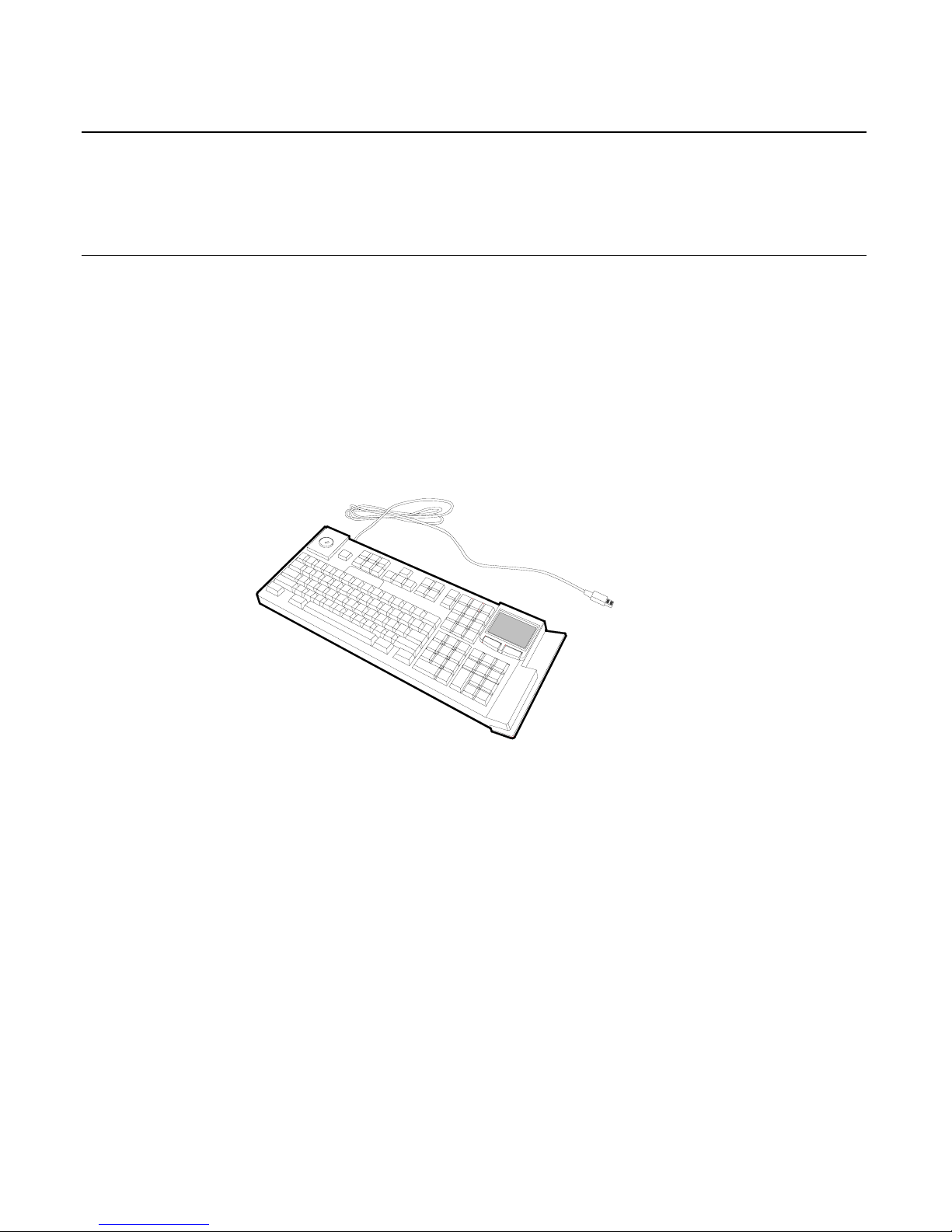
109 Key USB Keyboard
19586
The 109-key USB keyboard is a multifunction keyboard that is two
keyboards built into one.
The keyboard consists of two major sections:
• 38-key POS keyboard
• Industry-standard alphanumeric PC keyboard
The keyboard contains the key matrix and other POS-specific functions
such as Keylock, speaker, system status indicator, and magnetic stripe
reader (MSR). This 5932 keyboard also has a USB port to connect a
Scanner or other USB device.
Page 12

1-2 Chapter 1: General Overview
Model Number
The keyboard's 12-digit model number is located on its serial number
label. The model number identifies the keyboard features. The twelvedigit model number is defined in the following illustration.
5932 50 90 9006
Language Code
Major Model Code
Class Number
Sub Model Code
Power Code
19265
Major Model Code
Major Model Code Description
50 USB Keyboard
Sub Model Code
The following sub model codes identify features of the USB keyboard.
Sub Model Code Description
03 POS/USB Keyboard No MSR
06 USB Keyboard with 3 Track MSR and Keylock
07 USB Keyboard with Keylock and No MSR
08 USB Keyboard with 3 Track MSR and No Keylock
08 USB Keyboard with no Keylock and No MSR
Power Code
Power Code Description
90 All Countries, 50/60 Hz
Language Code
Language Code Description
90 No Language
Page 13

Chapter 1: General Overview 1-3
Features
The NCR 5932 USB Keyboard supports the following features:
• Keylock
• Speaker
• Magnetic Stripe Reader (MSR)
• Keyboard Status LEDs
Keylock
The USB keyboard has a four-position Keylock. You can rotate the
Keylock between specific positions by use of three keys. The positions
are explained in the following table.
Abbreviation Position Description
Ex Exception Used by the customer or service
representative to perform low
level programming such as
workstation diagnostics,
configuring the workstation, or
loading the workstation.
L Locked Used to lock keyboard input to
prohibit use of normal functions.
R Register Used when performing normal
retail mode functions.
S Supervisor Used by the supervisor to
provide highest level of
workstation control in cases such
as refunds and running totals.
Speaker
The programmable speaker is capable of generating key clicks and
error tones.
Page 14

1-4 Chapter 1: General Overview
MSR
The MSR is an optional feature that provides support for reading
magnetically coded data cards. The keyboards support two different
types of MSR:
• ISO Tracks 1, 2, and 3
• JIS-II and ISO Track 2
The MSR head is connected to the MSR Amplifier Assembly via the
MSR connector. The MSR Amplifier Assembly contains the
amplification circuitry, a PCB, cable, and connectors.
The MSR Amplifier Assembly is connected to the main PCB and
mounted internally into the keyboard housing by the supplier on every
unit. The intent is that when it becomes economically reasonable the
MSR Amplifier Assembly (with modification) would be added the to
MSR read head assembly kit and installed by the assemblers only when
the customer requested the MSR option.
Keyboard Status LEDs
The keyboard has three status LED’s:
• Num Lock
• Caps Lock
• Scroll Lock
These features are used to provide the present state of the keyboard.
The indicators are single color (Green) LED’s. When the system is off,
no LED’s are illuminated.
Page 15

Chapter 1: General Overview 1-5
Comparisons Between the PS/2 and USB Keyboards
Overview
The NCR 5932 USB Keyboard is a replacement for its predecessor, the
5932 PS/2 (wedge), with features and advantages not present in the
older product. This section is a discussion of those features with some
explanation of the advantages.
Summary
The NCR 5932 USB keyboard improves on its predecessor by taking
advantage of features of USB to increase flexibility and connectivity.
The major advances are:
1. Glide Pad integration
2. Full keyboard re-programmability
3. Added general-purpose connectivity via on-board USB port
4. Future optional fingerprint sensor module
There are also minor technical improvements, primarily a benefit for
systems integrators. One example is the ability for host software to
detect the presence or absence of the MSR, Keylock, and Glide Pad.
Another example is the use of standard USB protocols throughout and
even standard USB Human Interface Desine (HID) device classes
where such device standards exist. NCR went so far as to help develop
an additional standard in the case of the MSR. Use of such standards
eases the job of systems engineers and integrators.
Page 16

1-6 Chapter 1: General Overview
Discussion
The NCR 5932 line of keyboards contain, most basically, a set of keys in
a physical configuration that has been found useful to retailers. The
keyboards also come with additional features, some optional, that add
value to the retail environment. The following table lists these features.
Following the table are paragraphs that more fully explain the
terminology.
Feature 5932 PS/2 (wedge) 5932 USB
101-Key style keyboard Standard PS/2 Standard USB HID
Cappable Keys 26 26
Double-High /
Double-Wide Keys
Firmware Detected,
limited keys
Fully Programmable
Keyboard
Programmability
Fixed, limited Fully Programmable
Keylock 4 position wedge 4 position USB HID
Key Click Yes, programmable Yes, programmable
Error Tone Yes, wedge Yes, USB HID
MSR 3 track Wedge 3 track Standard USB
HID
Scanner port RS232, limited, pre-
qualified
See General Purpose USB
Port
Power LED Yes No
Glide Pad No Yes, Standard USB HID
Additional port No General Purpose USB
port for Scanner or any
USB 1.1 compliant
device.
Fingerprint sensor No Planned USB module
replaces Keylock
Page 17

Chapter 1: General Overview 1-7
101-Key style keyboard
The foundational difference between the NCR PS/2 keyboard and the
NCR USB keyboard is the communications between the keyboard and
the host computer. The PS/2 keyboard communicates using the PS/2
communications protocol, which is bit-serial and operates at
approximately 25 Kb. The USB keyboard uses the USB 1.1 protocol,
which is a different bit-serial protocol that operates at either 1.5 or 12
Mb. NCR’s keyboard operates at 12 Mb except for the Glide Pad, which
operates at 1.5 Mb.
Furthermore, each of these protocols includes a software layer. The
PS/2 software layer is very simplistic, and presents a challenge when
adding additional capabilities beyond the keyboard itself. All the
added devices, such as MSR, Keylock, tone, and scanner are
implemented as wedge devices. This means that these devices are
wedged into the keyboard data stream and must spoof their way past
the operating system to transfer data. This technique, though
widespread, is burdened with problems, and is not standardized,
resulting in installation and support difficulties.
The USB software layer is standardized and well defined. It supports
multiple simultaneous channels of communications, and permits
additional capabilities to be added without negative impact.
Furthermore, USB defines several levels of standards, including a
standard for Human Interface Devices. This standard specifies
behavior for many devices that are widely used in the computer
industry, and permits proprietary extensions to be added for those
devices that are less widely used. NCR’s USB keyboard includes both
fully standard HID devices, such as the keyboard itself, the Glide Pad,
and the MSR, and less-widely used and thus customized HID devices
such as the Keylock and Error Tone.
The USB keyboard implements a standard USB Hub internally. This
hub provides independent connectivity to the several functional
sections that comprise the keyboard.
Page 18

1-8 Chapter 1: General Overview
For many years, the standard in keyboards was the keyboard style
known as 101-Key. In recent years, with the broad acceptance of
Graphical User Interfaces, keyboards have added one or two GUI keys
and current keyboards are now called 102-Key or 103-Key style. The
NCR PS/2 keyboard does not contain these GUI keys. The NCR USB
keyboard does not have reserved positions for those keys, but permits
those keys to be added using the keyboard programmability (see
Keyboard Programmability).
Cappable Keys
Both USB and PS/2 NCR keyboards include keys that accept customerspecified key caps and labels. For example, one customer may wish to
include buttons for DEPT, CLASS, and SKU on his keyboard. A
different customer may have no use for these keys, but may want
TIRES, BATTERIES, and ACCESSORIES on specific keys. Cap-able
keys allow for this customization.
Double-High / Double-Wide Keys
Along with cap-able keys comes the ability to put caps over pairs of
plungers, resulting in larger keys. On a standard keyboard, the space
bar, the Enter key, the Tab, Delete, Shift, Control, and Alt keys are all
wider than the rest. These keys are implemented with one or two
plungers, but they cannot be modified for different functionality. On
NCR keyboards, the cap-able keys may be capped in pairs. Key caps
are available that cover two plungers, either double-high or double-wide.
When two keys are capped individually, the keyboard firmware must
detect each one as a different key, and must send different messages to
the host computer to indicate different keys were pressed. When the
same two keys are capped together, the firmware must somehow know
this and send only one message.
Page 19

Chapter 1: General Overview 1-9
With the 5932 PS/2, this is accomplished by using firmware that senses
both plungers and the time lag between the plungers. If adjacent
plungers are pressed within a certain interval, then the firmware only
sends one of the two. Which one it sends is fixed, and the time lag is
fixed. Thus, although this method works, it is subject to occasional
error due to small mechanical tolerance problems. It is also somewhat
limited in flexibility.
With the 5932 USB, the keyboard is fully programmable. Two keys that
are capped together can be programmed to literally BE the same key.
(Duplicate messages are discarded.) Thus there is no limit to the
flexibility, and no problem can be induced by the same minor
mechanical problems experienced with the 5932 PS/2 keyboard.
Keyboard Programmability
The 5932 PS/2 keyboard includes the ability to select whether the
keypad should be telephone- or calculator-style. This is implemented
with a simple toggle that selects which layout is to be selected. No
other programming is possible.
The 5932 USB keyboard includes full programmability of the keyboard.
Each and every key can be re-assigned as desired, and is only limited
by the capabilities of a standard USB-HID keyboard. Based on registry
entries, a program on the PC sends a complete keyboard layout matrix
to the keyboard firmware. From that moment on, the firmware sends
the newly assigned set of keys over the USB connection. No translation
software is required in the host PC.
New key values are assigned using registry entries. This means a
keyboard can be replaced in the field without any extra programming
steps. Once the terminal has been set up with key assignments, a
replacement keyboard will automatically receive the programmed key
assignments. Key assignments are sent from the registry whenever an
NCR USB keyboard is connected to the PC, whether at power-on or
hot-plugged.
Page 20

1-10 Chapter 1: General Overview
Each key can be programmed to be a dead key, one single key, or a
two-key combination. Most keys will be single key values. However
some keys may be programmed as a two-key combination. For
example, the combination of Shift and F1 key values may be used to
provide compatibility with the 5932 PS/2 keyboard. A double-zero key
is another potential use for this feature. Any combination of up to two
key values may be assigned to a single plunger on the keyboard.
The registry values can be managed using a simple text editor along
with the operating system supplied registry editor. Alternatively, a
GUI utility (non-supported) is available for visually manipulating the
key assignments in the registry (see Key Re-mapping Registry
Manipulation Tool).
Keylock
Both PS/2 and USB keyboards include a four-position Keylock. All
PS/2 keyboards have a Keylock, whereas in the USB keyboard, it is
optional.
The PS/2 keyboard implements the Keylock as a wedge device. The
USB keyboard implements the Keylock as a separate HID device.
Because USB is designed for plug-and-play (PnP), the presence or
absence of the Keylock is easily detected by the host software.
In both keyboards, placing the key in the L (Locked) position disables
the keyboard. In the PS/2 keyboard, the MSR and the external scanner
port are disabled. In the USB keyboard, the MSR, the Glide Pad and the
external USB port are all disabled.
Key Click
Both PS/2 and USB keyboards provide a small speaker that can be
used to make a key click sound. The exact sound made for key clicks is
programmable in both devices, and the sounds available are
comparable.
Page 21

Chapter 1: General Overview 1-11
Error Tone
Both PS/2 and USB keyboards incorporate the ability for host software
to evoke an error tone at the keyboard using the key click speaker. The
capabilities are comparable.
MSR
Both PS/2 and USB keyboards provide an optional 3-track MSR in
either ISO or JIS head configurations. The PS/2 keyboard cannot
detect if the MSR is present.
The USB keyboard implements the MSR as a separate USB HID device,
conforming to the published HID standard for MSR devices. As with
the Keylock, the PnP feature of USB communications makes it a simple
matter for the host computer and thus the customer’s application to be
aware of the presence or absence of the MSR.
Scanner port
The PS/2 keyboard contains an NCR-proprietary RJ-45 connection for
RS-232 based scanners. This port has technical limitations and a limited
subset of NCR scanners are qualified.
The USB keyboard has no RJ-45 connector for RS-232 scanners.
However see Additional Port.
Additional port
The PS/2 keyboard has no additional ports beyond the Scanner port.
The USB keyboard provides a standard USB port connection to one of
the internal hub’s ports. This connection permits a USB scanner, or for
that matter, any standard USB device to be connected through the
keyboard to the host computer.
Power LED
The PS/2 keyboard has an LED that indicates when power is present.
The USB keyboard has no such LED.
Page 22

1-12 Chapter 1: General Overview
Glide Pad
The PS/2 keyboard has no Mouse, Trackball, or Glide Pad capability.
The USB keyboard supports an optional Glide Pad. The Glide Pad is a
standard USB HID mouse-type device, seen within the host computer
software as separate from each of the other independent USB devices.
As with the other USB PnP components of the USB keyboard, the
presence or absence of the Glide Pad is easily detected in the host
computer.
Fingerprint sensor
The USB keyboard has been designed to accommodate a Fingerprint
Sensor Module. This module replaces the Keylock module, and
operates as another independent USB device through the internal hub.
Page 23
Chapter 1: General Overview 1-13
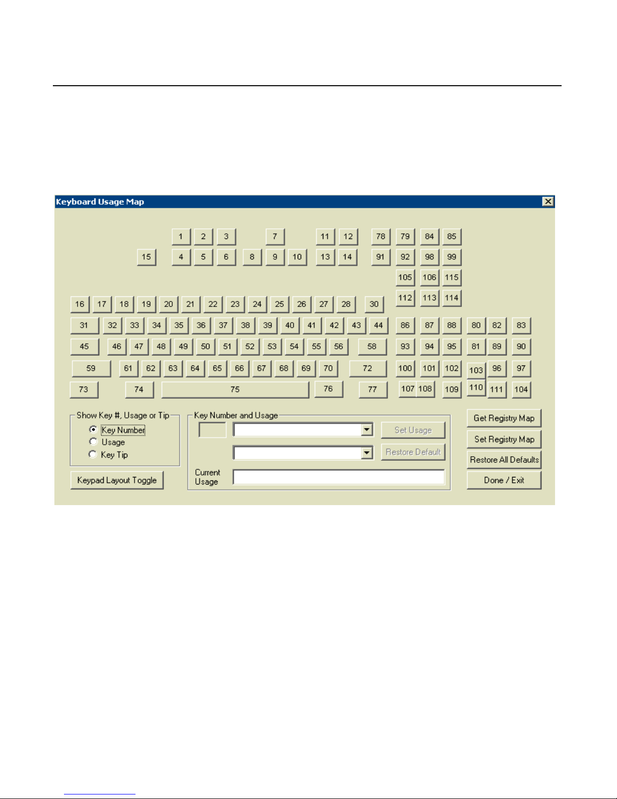
Key Re-mapping Registry Manipulation Tool
A GUI Active-X control for Windows is available (though nonsupported) to simplify manipulation of the keyboard re-mapping
registry entries.
The Show Key #… radio buttons in the lower left allow the user to select
whether to display the key tips, the HID usage values, or the NCRdesignated Key Number for display
Clicking on an individual key highlights the key and enables the Key
Number and Usage box. The current assignment is shown and two new
key usages may be selected from the drop down boxes. Once selected,
the new value can be assigned using the Set Usage button. The default
value can be restored with the Restore Default button.
A common need is to be able to toggle the keypad number layout
between telephone and calculator style, so a special button is available
for that function.
Page 24

1-14 Chapter 1: General Overview
The values currently stored in the Registry for NCR 5932 USB
keyboards can be retrieved by clicking the Get Registry Map button. The
only values stored in the registry are the values that are non-default.
All of the keys can be restored to default values with the Restore All
Defaults button.
After assigning new values to keys or restoring default values, the
values may be written to the registry using the Set Registry Map button.
This is the only action that actually causes the registry to be written. All
other actions are held in program memory for display on the GUI.
Only clicking this button will cause the current values to be saved.
The Done/Exit button exits the control. If the Done/Exit key is pressed
without pressing the Set Registry Map button, then no modifications are
saved.
Page 25

Chapter 2: Installation
Environmental Conditions
Physical Environment
This section lists the physical and electrical environments required for
the NCR 5932 USB Keyboards.
Operating Range
Condition Range
Temperature 5°C to 45°C (40°F to 113°F)
Relative Humidity 10% to 90%
Non-condensing
Barometric Pressure 15.2 to 0.2 psi up to a
maximum of 9,850 feet
Storage Range
Condition Range
Temperature
-10° to 50°C (14°F to 120°F)
Temperature Change
15°C (27°F) per hour max.
Relative Humidity 10% to 90%
Page 26

2-2 Chapter 2: Installation
Transit Range
Condition Range
Temperature
-40° to 60°C (-40°F to 140°F)
Temperature Change
20°C (36°F) per hour max.
Relative Humidity 5% to 95%
Condensation may occur when equipment is transferred from cold to
warm areas during shipment. If flash condensation has occurred, only
operate the keyboard after the equipment has dried and been stabilized
to the operating environment.
Electrical Environment
The electrical environment required for the keyboard module is listed
as follows.
Parameter Symbol Min Max
Supply voltage to keyboard VIN 4.75V 5.25v
Supply current to keyboard IIN 500 mA
Supply voltage to USB Port VOUT 4.75V 5.5V
Supply current to USB Port IOUT 100mA
Note: The user programmable speaker tone function on the USB
keyboards is not supported when the keyboard is connected to a
standard PC. The standard PC keyboard voltage tolerance is not
sufficient to handle the extra power requirements of the programmable
speaker tone. Only the default keyclick and error tones are supported
on a PC.
Caution: Be sure to turn off your PC or retail workstation BEFORE
you plug in the keyboard. “Hot plugging” can result in damage to your
PC due to the increased power requirements of the USB keyboards.
Page 27

Chapter 2: Installation 2-3
Operational Environment
The following parameters apply to keyboard operations.
System Configuration
No keyboard configuration is required at installation time. The
keyboard is configured at the time of manufacture by default to
recognize the Ctrl-Alt-Del key combination for system reset.
Unit Setup
No unit setup is required at installation time, unless configuration
must be changed from factory defaults.
Diagnostics
Upon Powering Up or receiving a reset, the keyboard initializes by:
• Clearing RAM
• Resetting the indicator lights
Additionally, if a stuck key condition is detected, the USB HID
Keyboard usage ID of the stuck key is returned following the
successful status.
Page 28

2-4 Chapter 2: Installation
Physical Size
19650
184 mm
(7.25 in.)
35 mm
(1.4 in.)
455 mm
(17.9 in.)
45 mm
(1.7 in.)
Page 29

Chapter 2: Installation 2-5
Installing the Keyboard
Caution: The power supply cord is used as the main disconnect
device. Ensure that the socket outlet is located/installed near the
equipment and is easily accessible.
Le cordon d’alimentation est utilisé comme interrupteur général. La
prise de courant doit être située ou installée a proximite du matériel et
être facile d’accés.
Installation Goal
The goal for installing the keyboards is for a reasonably trained
operator or store manager to fully install the workstation in less than
10 minutes.
To qualify as “reasonably trained” an installer or store manager must
be fluent with the terminology and basic technology of PC hardware
and software. This level of knowledge can typically be found in an
individual who has installed several PC systems, and who routinely
uses a PC for personal or business computing.
Cable Connections
The keyboard communicates with the host system via a single USB
compatible interface. They keyboard cable is a USB 1.1 compliant cable.
The mating connector to the host is a UBS Series “A” plug and the
keyboard side of the cable is enclosed with sufficient strain relief. The
keyboard conforms to all operational and non-operational vibration
and shock requirements.
The length of the cable from the keyboard cabinet to the end of the
connector is 70.1+
0.5 inches. One end of the cable is to be internally
connected but not soldered and clamped to the printed circuit board of
the keyboard.
Page 30

2-6 Chapter 2: Installation
The pin assignments for the connector are shown below.
Contact Number Signal Name Typical Wiring Assignment
1 VBUS Red
2 D- White
3 D+ Green
4 GND Black
Shell Shield Drain Wire
USB Keyboard Scanner Connection
The USB keyboard may be connected to a USB hand held scanner or
other USB device as shown in the following illustration.
19587
USB
Cable
USB
Connector
Page 31

Chapter 2: Installation 2-7
Powering Up
This section describes powering up the workstation and the initial
checkout procedures after all hardware has been installed.
Note: No keyboard configuration is required at installation time. The
keyboard is configured at the time of manufacture by default to
recognize the Ctrl-Alt-Del key combination for system reset.
Note: No unit setup is required at installation unless configuration
must be changed from factory defaults.
Powering up procedures is described for the keyboard when
configured with:
• PC
• 7452/53 Workstation
• 7451 & 7456 Workstations
Power Up Procedures
Plug the USB keyboard Cord into a USB port on the workstation.
1. Turn the Keylock to the Ex position.
2. Power on the workstation.
Page 32

2-8 Chapter 2: Installation
USB Keyboard
The USB keyboard key layout is shown below.
6766656463626159
73 74 75
48
32
1716
45
31
1918
47
334634
15
222120
493550
36
45
2423
513752
38
68
123
102101100
72706968
76 77
107 108 109
71211
55
2625
40
533954
41
910
2827
56
42 43
13 14
85847978
30
58
44
93
86
91
112
105
92
948795
88
113
106
98
114
115
99
9796103
104111110
90
83
8981
80 82
Num
Loc k
Loc k
Caps
Loc k
Sc ro l l
Down
Page
Up
Page
Pause
Screen
Print
Lock
Num
Lock
Scroll
0
1
4
7
526
3
8
9
O
<
Shift
M
N
V
C
X
B
Z
Ctrl Al t
,
3
#
W
Q
Caps
Lock
S
A
1
Tab
~
!
2
@
T
R
E
DGF
4
$
6
5
%
I
U
Y
J
H
K
7
&
*
9
8
(
>
?
Shift
Alt
/
Ctrl
CR
P
L
[ ]
0
-
)
=
{
}
+
B
a
c
k
s
p
a
c
e
ScrollCapsNum
Lock Lock Lock
ESC
Home
EndDelete
Insert
19759
F1 F2 F3 F4
F5 F6 F7 F8
F9 F10 F11
F12
LShft
+F3
+
*
-
/
E
N
T
E
R
LShft
+F4
LShft
+F5
LShft
+F6
LShft
+F7
LShft
+F8
LShft
+F9
LShft
+F10
Page 33

Chapter 2: Installation 2-9
Keycode Charts
The following tables correlate the keyboard key number, unshifted
character and scan code for the USB keyboard
USB Keyboard Keycode Table
Key Number Unshifted Character USB HID Keyboard Usage ID (h)
1 Insert 49
2 Home 4A
3 Page Up 4B
4 Delete 4C
5 End 4D
6 Page Down 4E
7
↑ (up arrow)
52
8
← (left arrow)
50
9
↓ (down arrow)
51
10
→ (right arrow)
4F
11 Pause 48
12 Scroll Lock 47
13 Print Screen 46
14 Num Lock 53
15 Esc 29
16 ‘ (apostrophe) 35
17 1 1E
18 2 1F
19 3 20
20 4 21
21 5 22
22 6 23
23 7 24
24 8 25
25 9 26
Page 34

2-10 Chapter 2: Installation
Key Number Unshifted Character USB HID Keyboard Usage ID (h)
26 0 27
27 — 2D
28 = 2E
30 Backspace 2A
31 Tab 2B
32 q 14
33 w 1A
34 e 08
35 r 15
36 t 17
37 y 1C
38 u 18
39 i 0C
40 o 12
41 p 13
42 [ 2F
43 ] 30
44 \ 31
45 Caps Lock 39
46 a 04
47 s 16
48 d 07
49 f 09
50 g 0A
51 h 0B
52 j 0D
53 k 0E
54 l 0F
55 ; 33
56 ‘ (single quote) 34
58 Return 28
59 Shift (left side) E1
Page 35

Chapter 2: Installation 2-11
Key Number Unshifted Character USB HID Keyboard Usage ID (h)
61 z 1D
62 x 1B
63 c 06
64 v 19
65 b 05
66 n 11
67 m 10
68 , (comma) 36
69 . (period) 37
70 / (forward slash 38
72 Shift (right side) E5
73 Ctrl (left side) E0
74 Alt (left side) E2
75 Space 2C
76 Alt (right side) E6
77 Ctrl (right side) E4
78 F1 3A
79 F2 3B
80 Left Shift-F5 E13E
81 Left Shift-F8 E141
82 Left Shift-F6 E13F
83 Left Shift-F7 E140
84 F3 3C
85 F4 3D
86 7 5F
87 8 60
88 9 61
89 Left Shift-F9 E142
90 Left Shift-F10 E143
91 F5 3E
92 F6 3F
93 4 5C
Page 36

2-12 Chapter 2: Installation
Key Number Unshifted Character USB HID Keyboard Usage ID (h)
94 5 5D
95 6 5E
96 + 57
97 * 55
98 F7 40
99 F8 41
100 1 59
101 2 5A
102 3 5B
103 ENTER 58
104 / 54
105 F9 42
106 F10 43
107 0 62
108 0 62
109 . 63
110 Enter 58
111 - 56
112 F12 45
113 Left Shift-F3 E13C
114 Left Shift-F4 E13D
115 F11 44
Page 37

Chapter 2: Installation 2-13
Labels
External Nameplate
Each keyboard is marked with the NCR part number and revision
level. The suppliers' sequential serial or tracking number and the
suppliers' UL and CSA files numbers, around its respective marking.
Page 38

2-14 Chapter 2: Installation
Barcode/Serial Number Label
The 5932 USB Keyboard has a barcode/serial number label as specified
in NCR document 497-0422987. The label material is:
NCR System Media 901840 Thermal Top Coated Permanent Adhesive.
An example is shown below.
NCR
5932-MMSM-VFLL
70-NNNNNNNN
Mfg. Date: xx/xx/xx
19911
Where:
MM = 2 digit Major Model Code
SM = 2 digit Sub Model Code
VF = 2 digit Voltage and Frequency Code
LL = 2 digit Language Code
NN = 8 digit Serial Number (Unique Number for each keyboard)
Mfg Date = 2 digit month/2 digit day/2 digit year of manufacture
Page 39

Chapter 2: Installation 2-15
Weights and Measures Label
The 5932 USB Keyboard has a Weights and Measures label. The label
material is 3M #7380 tamper indicating polyester, with 3M #7745
imprintable laminate.
An example is shown below.
Page 40

Page 41

Chapter 3: Programming
Firmware
USB Keyboard Capabilities
The NCR USB Keyboard is a multifunction device comprised of several
functions, including a keyboard switch matrix and a speaker. Both of
these functions are controlled by a single field programmable gate
array (FPGA).
The keyboard matrix translates between a key switch physical location
and the key data reported to the host PC. This matrix is programmable.
The matrix may be replaced in whole or in part, permitting any key to
be mapped to any function.
The FPGA has the ability to sound a short chirp whenever a key is
pressed, providing auditory feedback to an operator of the keyboard.
This auditory feedback is optional. The FPGA may be configured to
make the sound or not to make the sound, depending on the particular
application.
The FPGA has no static memory and thus cannot retain any settings
after power loss. Thus, each time the system to which this keyboard is
connected is powered-up, or any time the keyboard is connected to a
powered system, the FPGA must be informed of any pertinent settings.
This function is an ActiveX/COM control (NCRUsbKeyboardCtl) that
provides a mechanism by which the keyboard features of “key click
sound” and “key translation matrix” can be set.
The keyboard firmware is standard USB compatible keyboard
firmware with added extensions for POS-specific functions.
Page 42

3-2 Chapter 3: Programming
The keyboard supports the following minimum standard PC keyboard
capabilities:
• System Reset (Control-Alt-Delete)
The keyboard has additional capabilities unique to the POS
environment. The keyboard firmware supports the following POS
functions:
• Programmable keyboard matrix
• Configurable keyclick tone
• Calculator or Telephone style numeric keypad configuration
FPGA Firmware Defaults
During USB initialization all USB devices are required to enumerate.
Each device reports its data and ID to the host where the Host USB
driver sends the report to the corresponding USB Device Driver.
Power Up and Reset POS Default Conditions:
• Default keyboard matrix configuration
• Calculator style numeric keypad configuration
• Num Lock On.
Unique POS Capabilities
The keyboard firmware supports the following POS-specific extensions
to the standard PC firmware:
• Programmable Key Matrix
• Configurable Keyclick Tone
• NCR Platform Software Components
Page 43

Chapter 3: Programming 3-3
NCRUsbKeyboardCtl HID usages
NCRUsbKeyboardCtl employs industry standard and NCR Proprietary
HID Usage interfaces to exercise the keyboard control programming
capability of the firmware. The NCR Proprietary usages are contained
in the following table:
Table 1: NCR Proprietary HID Usages
Usage Hexadecimal Value
HID_USAGE_PAGE_NCR_MISC 0xFF8F
KEYLOCK 0x01
KEYBOARD_TONE 0x02
KEYBOARD_MAP 0x03
KEY_CLICK_INFO 0x11
ERROR_TONE 0x12
TONE FREQUENCY 0x21
TONE DURATION 0x22
TONE VOLUME 0x23
KEY_MATRIX_USAGE 0x31
Page 44

3-4 Chapter 3: Programming
The report descriptors as emitted by the HID device should be
consulted as the authority for the format of the reports. Software
should access fields using report descriptor-based techniques and
should not assume that all revisions of the product use identical report
descriptors. The following provides interpretation information for
these reports.
Keylock hardware HID interface: The keylock reports its
positions as HID buttons. The positions are assigned as follows:
• Button 1 = Ex
• Button 2 = L
• Button 3 = R
• Button 4 = S.
Tone hardware interface: The ErrorTone usage collects a tone
output report that sounds an immediate tone. The KeyClick usage
collects a tone output report that sets the sound made for a key
click. The units for Duration are milliseconds. The volume is a value
between Logical_Minimum (silent) and Logical_Maximum (greatest
volume). The tone is an index from Table 2: Note Numbers and
Frequencies.
The MSR interface: The MSR conforms to the USB HID standard
for MSRs as described in the HID Usage Tables for POS, Ver 1.02,
see http://www.usb.org/developers/hidpage.html#pos
.
The Key Matrix: The Key Matrix report contains an overlay for the
keyboard look-up table. It is organized in FPGA Offset order, and
contains pairs of 8-bit usages, one pair per key position. Values of
zero produce no usage report. Two different usages produce two
simultaneous usages being reported. The number of positions is
given by the report descriptor.
Page 45

Chapter 3: Programming 3-5
Programmable Key Matrix
The keyboard matrix is completely programmable, translating between
a key switch physical location and the key data reported to the host PC.
Through this keyboard provision, you can switch the numeric keypad
layout from the default calculator layout to a telephone layout by
organizing the keyboard matrix to mimic either mode of operation.
Note: If you change the numeric keypad layout, you must also
physically remove and swap the key caps on the first and third rows of
the keypad. The key codes for the numeric keypad are identical to the
IBM PS/2, 101-key keyboard.
Double-high/Double-wide Keys
Several keys on the keyboard can accept optional keycaps that cover
two keys to produce double-high or double-wide keys. When you
press a double-high or double-wide keycap, the keyboard firmware
sends the keycode for both keys. When usages are the same, only one
keycode is sent. Using the programmable key matrix feature, the
keyboard matrix can be programmed to support double-high or
double-wide keys by specifying the same key code for both key
locations supported by the key cap.
Keyboard Matrix for 5932 USB Keyboard (PID 0x0320)
The keyboard matrix comprises a list of key numbers and respective
positions within the keyboard translation table. The default keyboard
map for the 5932 USB Keyboard (PID 0x0320) is as follows:
Sorted by Key Number Sorted by Offset Sorted by Usage
Key
Number Usage
FPGA
Offset
FPGA
Offset
Key
Number Usage
Usage
FPGA
Offset
Key
Number
1 49 0 0 1 49 0 104 29
2 4A 16 1 16 35 0 105 57
3 4B 24 2 31 2B 0 106 60
4 4C 8 3 96 57 0 108 71
5 4D 40 4 45 39 0 111 116
Page 46

3-6 Chapter 3: Programming
Key
Number Usage
FPGA
Offset
FPGA
Offset
Key
Number Usage
Usage
FPGA
Offset
Key
Number
6 4E 48 5 15 29 0 112 117
7 52 32 6 109 63 0 113 118
8 50 64 7 110 58 0 114 119
9 51 56 8 4 4C 0 116 120
10 4F 72 9 17 1E 0 117 121
11 48 88 10 32 14 0 119 122
12 47 80 11 83 E140 0 120 123
13 46 102 12 46 4 0 121 124
14 53 96 13 61 1D 0 122 125
15 29 5 14 89 E142 0 124 126
16 35 1 15 108 62 0 125 127
17 1E 9 16 2 4A 0 127 128
18 1F 17 17 18 1F 4 12 46
19 20 25 18 33 1A 5 45 65
20 21 33 19 78 3A 6 29 63
21 22 41 20 47 16 7 28 48
22 23 49 21 62 1B 8 26 34
23 24 57 22 97 55 9 36 49
24 25 65 23 85 3D 10 61 67
25 26 73 24 3 4B 11 53 66
26 27 81 25 19 20 12 74 40
27 2D 89 26 34 8 13 82 41
28 2E 97 27 115 44 14 10 32
29 0 104 28 48 7 15 34 35
Page 47

Chapter 3: Programming 3-7
Key
Number Usage
FPGA
Offset
FPGA
Offset
Key
Number Usage
Usage
FPGA
Offset
Key
Number
30 2A 86 29 63 6 16 20 47
31 2B 2 30 99 41 17 42 36
32 14 10 31 84 3C 18 58 38
33 1A 18 32 7 52 19 37 64
34 8 26 33 20 21 20 25 19
35 15 34 34 35 15 21 33 20
36 17 42 35 82 E13F 22 41 21
37 1C 50 36 49 9 23 49 22
38 18 58 37 64 19 24 57 23
39 0C 66 38 95 5E 25 65 24
40 12 74 39 81 E141 26 73 25
41 13 82 40 5 4D 27 81 26
42 2F 90 41 21 22 28 94 58
43 30 98 42 36 17 29 5 15
44 31 92 43 80 E13E 30 98 43
45 39 4 44 50 0A 31 92 44
46 4 12 45 65 5 33 84 55
47 16 20 46 102 5B 34 93 56
48 7 28 47 101 5A 35 1 16
49 9 36 48 6 4E 36 69 68
50 0A 44 49 22 23 37 77 69
51 0B 52 50 37 1C 38 85 70
52 0D 60 51 103 58 39 4 45
53 0E 68 52 51 0B 40 59 98
Page 48

3-8 Chapter 3: Programming
Key
Number Usage
FPGA
Offset
FPGA
Offset
Key
Number Usage
Usage
FPGA
Offset
Key
Number
54 0F 76 53 66 11 41 30 99
55 33 84 54 100 59 42 83 105
56 34 93 55 114 E13D 43 63 106
57 0 105 56 9 51 44 27 115
58 28 94 57 23 24 45 87 112
59 E1 123 58 38 18 46 102 13
60 0 106 59 98 40 47 80 12
61 1D 13 60 52 0D 48 88 11
62 1B 21 61 67 10 49 0 1
63 6 29 62 92 3F 50 64 8
64 19 37 63 106 43 51 56 9
65 5 45 64 8 50 52 32 7
66 11 53 65 24 25 53 96 14
67 10 61 66 39 0C 54 103 104
68 36 69 67 88 61 55 22 97
69 37 77 68 53 0E 56 101 111
70 38 85 69 68 36 57 3 96
71 0 108 70 94 5D 58 51 103
72 E5 126 71 86 5F 58 7 110
73 E0 115 72 10 4F 59 54 100
74 E2 107 73 25 26 60 79 87
75 2C 109 74 40 12 61 67 88
76 E6 110 75 113 E13D 62 100 107
77 E4 118 76 54 0F 62 15 108
Page 49

Chapter 3: Programming 3-9
Key
Number Usage
FPGA
Offset
FPGA
Offset
Key
Number Usage
Usage
FPGA
Offset
Key
Number
78 3A 19 77 69 37 63 6 109
79 3B 95 78 93 5C 0A 44 50
80 E13E 43 79 87 60 0B 52 51
81 E141 39 80 12 47 0C 66 39
82 E13F 35 81 26 27 0D 60 52
83 E140 11 82 41 13 0E 68 53
84 3C 31 83 105 42 0F 76 54
85 3D 23 84 55 33 1A 18 33
86 5F 71 85 70 38 1B 21 62
87 60 79 86 30 2A 1C 50 37
88 61 67 87 112 45 1D 13 61
89 E142 14 88 11 48 1E 9 17
90 E143 99 89 27 2D 1F 17 18
91 3E 91 90 42 2F 2A 86 30
92 3F 62 91 91 3E 2B 2 31
93 5C 78 92 44 31 2C 109 75
94 5D 70 93 56 34 2D 89 27
95 5E 38 94 58 28 2E 97 28
96 57 3 95 79 3B 2F 90 42
97 55 22 96 14 53 3A 19 78
98 40 59 97 28 2E 3B 95 79
99 41 30 98 43 30 3C 31 84
100 59 54 99 90 E143 3D 23 85
101 5A 47 100 107 62 3E 91 91
Page 50

3-10 Chapter 3: Programming
Key
Number Usage
FPGA
Offset
FPGA
Offset
Key
Number Usage
Usage
FPGA
Offset
Key
Number
102 5B 46 101 111 56 3F 62 92
103 58 51 102 13 46 4A 16 2
104 54 103 103 104 54 4B 24 3
105 42 83 104 29 0 4C 8 4
106 43 63 105 57 0 4D 40 5
107 62 100 106 60 0 4E 48 6
108 62 15 107 74 E2 4F 72 10
109 63 6 108 71 0 5A 47 101
110 58 7 109 75 2C 5B 46 102
111 56 101 110 76 E6 5C 78 93
112 45 87 111 116 0 5D 70 94
113 E13C 75 112 117 0 5E 38 95
114 E13D 55 113 118 0 5F 71 86
115 44 27 114 119 0 E0 115 73
116 0 111 115 73 E0 E1 123 59
117 0 112 116 120 0 E13C 75 113
118 0 113 117 121 0 E13D 55 114
119 0 114 118 77 E4 E13E 43 80
120 0 116 119 122 0 E13F 35 82
121 0 117 120 123 0 E140 11 83
122 0 119 121 124 0 E141 39 81
123 0 120 122 125 0 E142 14 89
124 0 121 123 59 E1 E143 99 90
125 0 122 124 126 0 E2 107 74
Page 51

Chapter 3: Programming 3-11
Key
Number Usage
FPGA
Offset
FPGA
Offset
Key
Number Usage
Usage
FPGA
Offset
Key
Number
126 0 124 125 127 0 E4 118 77
127 0 125 126 72 E5 E5 126 72
128 0 127 127 128 0 E6 110 76
Configurable Key Click Tone
The FPGA has the ability to sound a short chirp whenever a key is
pressed, providing auditory feedback to an operator of the keyboard.
This auditory feedback is optional. The FPGA may be configured to
make the sound or not to make the sound, depending on the particular
application.
USB Keyboard Tone Frequencies
The frequency is transmitted to the FPGA as a Note Number. Note
numbers are equivalent to specific frequencies. The note number sent
to the FPGA is selected by rounding the requested frequency to the
nearest frequency number given by the table of Note Numbers (N) and
Frequencies (freq) listed in the following table.
Table 2: Note Numbers and Frequencies
Note N freq N freq N freq N freq N freq N freq
A
0 28 24 110 48 440 72 1760 96 7040 120 28160
Bb
1 29 25 117 49 466 73 1865 97 7459 121 29834
B
2 31 26 123 50 494 74 1976 98 7902 122 31609
C
3 33 27 131 51 523 75 2093 99 8372 123 33488
Db
4 35 28 139 52 554 76 2217 100 8870 124 35479
D
5 37 29 147 53 587 77 2349 101 9397 125 37589
Eb
6 39 30 156 54 622 78 2489 102 9956 126 39824
E
7 41 31 165 55 659 79 2637 103 10548 127 42192
F
8 44 32 175 56 698 80 2794 104 11175
Page 52

3-12 Chapter 3: Programming
Note N freq N freq N freq N freq N freq N freq
Gb
9 46 33 185 57 740 81 2960 105 11840
G
10 49 34 196 58 784 82 3136 106 12544
Ab
11 52 35 208 59 831 83 3322 107 13290
A
12 55 36 220 60 880 84 3520 108 14080
Bb
13 58 37 233 61 932 85 3729 109 14917
B
14 62 38 247 62 988 86 3951 110 15804
C
15 65 39 262 63 1047 87 4186 111 16744
Db
16 69 40 277 64 1109 88 4435 112 17740
D
17 73 41 294 65 1175 89 4699 113 18795
Eb
18 78 42 311 66 1245 90 4978 114 19912
E
19 82 43 330 67 1319 91 5274 115 21096
F
20 87 44 349 68 1397 92 5588 116 22351
Gb
21 92 45 370 69 1480 93 5920 117 23680
G
22 98 46 392 70 1568 94 6272 118 25088
Ab
23 104 47 415 71 1661 95 6645 119 26580
Note: The frequency “f” is given by the equation :
12
N
25.27 ×≈
f
This table provides the full set of frequencies defined, however the
hardware itself may not generate all of these frequencies, and the
frequencies actually generated may not exactly match any of the
frequencies listed. Lower frequency numbers produce lower tones, and
higher frequency numbers produce higher tones.
NCR Platform Software Components
NCR provides three platform software components for configuring the
keyboard: the NCR USB Keyboard Control, the Set USB Key Matrix
application and the Set USB Key Clicks application.
Page 53

Chapter 3: Programming 3-13
NCR USB Keyboard Control
NCRUsbKeyClickCtl is an ActiveX control that contains a method for
setting the key clicks SetClicks, and a method for downloading the key
translation matrix information, SetKeyMatrix.
The SetClicks method examines all currently-enumerated HID devices,
finds those with a Vendor-ID equal to NCR’s assigned Vendor ID
(0x0404). Among all qualified devices found, each device is searched
for a KEY_CLICK_INFO feature report that contains Volume, Frequency,
and Duration usages. When a matching device is found, that device’s
product ID (PID) is used to locate keyclick values within the Registry.
The values found in the registry are sent to the device in the
KEY_CLIC_INFO feature report.
Each time SetClicks is invoked, it reads Volume, Frequency, and Duration
keyclick parameters from the registry. If these parameters are not
found in the registry, default values are written to the registry, and
these default values are used. This causes the registry to contain the
values most recently sent to NCR HID KeyClick devices.
The default values for Volume, Frequency, and Duration,
SetUsbKeyClick are 15, 1318, and 16, respectively.
The SetKeyboardMatrix method examines all currently-enumerated
HID devices, finds those with a Vendor-ID equal to NCR’s assigned
Vendor ID (0x0404). Among all qualified devices found, each device is
searched for a KEYBOARD_MAP feature report that contains an array
of KEY_MATRIX_USAGE usages, When a matching device is found,
that device’s PID is used to locate Key Matrix entries in the Registry. If
no Key Matrix values are found for that specific PID, no Key Matrix
download is performed.
For each KEYBOARD_MAP device located, SetKeyboardMatrix creates a
full default keyboard matrix that duplicates the factory-default matrix
of the specific product located. Next, the registry is read for
replacement values within the Keyboard Matrix. All registry values
found in the appropriate registry key are replaced within the default
matrix. Finally, the full key matrix as modified by registry values is
sent to the keyboard using the KEYBOARD_MAP feature report.
Page 54

3-14 Chapter 3: Programming
NCR USB Keyboard Control Parameterization Registry Values
Program Parameterization Registry values appear under the registry
key:
[HKEY_LOCAL_MACHINE\SOFTWARE\NCR\USBKeyboard\PID_0320\]
Table 3: Key-Value Definitions
Keyword1 Value (Decimal numbers) Default Registry
KeyClick\frequency2
A frequency between
27Hz and 42192 Hz
1760 DWORD
KeyClick\volume2
A value between 0
and 15
15 DWORD
KeyClick\duration2
A number of
milliseconds (0 - 1023)
the sound should be
produced
23 DWORD
KeyMatrix\keynumber 3
A single keyboard
usage to be installed
for keynumber
per key
matrix
section for
PID_0320
DWORD
1
Keywords are not case sensitive.
2
The Keywords frequency, volume, and duration and their values as sent
to the keyboard tone device are written to the registry. This enables a
systems management program to determine current keyclick settings.
3
The keynumber value name is a decimal number that must be one of
the possible key numbers for the designated product. For example,
“SetKeyboardKeyEntry(0320)” requires the registry contain a key
named
HKLM\Software\NCR\USBKeyboard\PID_0320\KeyMatrix, and
under this key there must be one or more values with names “1”
through “128” that correspond to the key numbers.
Page 55

Chapter 3: Programming 3-15
NCR USB Keyboard Control Data Capture Registry Values
NCR Data Capture Registry values appear under the registry key:
[HKEY_LOCAL_MACHINE\SOFTWARE\NCR\NCRUsbKeyboardCtl\DataCapture]
"DcapControl"="10 (Hex destination(s): 1=DCap App, 2=Debugger,
4=File; 10/20/40 for immediate)"
"DcapFile"="C:\\NcrDataCap.log"
"DcapFileMax"="0 (Max KB of data cap file)"
"DcapMask"="00000003 (Hex mask of events to capture)"
"DcapTime"="1F00 (Hex time option(s): 100=m:s, 300=h:m:s,
700=m/d h:m:s; 800+digits=millisec; 1000=threadid)"
"DcapVersion"="1.1.3"
"DcapLinePrefix"="NCRUsbKeyboardCtl "
Set DcapMask to 0x01 to receive only Error messages. Set to 0x02 or
higher receives all messages.
Set USB Key Matrix Application
SetUsbKeyMatrix is a Windows application for the Desktop O/S
versions (Windows 98se, Windows 2000) that uses the
NCRUsbKeyboardCtl control to set a keyboard matrix map. The
application operates as a memory-resident background process for a
duration that may be specified on the command line. If no duration is
specified, the application remains resident until terminated by user
action. While resident, the application receives device-attachment
notifications for HID devices, and when these are received, invokes
the NCRUsbKeyboardCtl control to set the keyboard matrix map.
Command-line parameters may include a value for the runtime
duration. If specified, the application remains resident only for the
requested duration. This permits the application to be used only
during defined events such as system start-up, and after which the
application will no longer remain resident in memory. The commandline parameters may also specify that a background memory-resident
instance of the application should be terminated. In this case, the
application only terminates the background instance, and does not
remain resident itself or invoke the control to set the keyboard matrix
map.
Page 56

3-16 Chapter 3: Programming
SetUsbKeyMatrix may be launched “by hand” using the Windows Start
> Run option, or any equivalent shortcut technique (desktop, quicklaunch pad, menu). If started in this manner, the command line can
optionally contain strings of the form “keyword{= value}”, where
keyword is one of the defined parameters, and value is an optional
numeric value to be applied to that key.
The following table gives the available command-line parameters.
Table 4: Command-line Parameters
Keyword1 Value (Decimal numbers) Value
Close Close any background session found n/a
runtime A number of seconds to remain resident,
waiting for additional devices to
initialize.
0 = indefinitely
1
Keywords are not case sensitive, and may be abbreviated to 3 or more
characters.
Set USB Key Clicks Application
SetUsbKeyClick is a Windows application for the Desktop O/S versions
(Windows 98se, Windows 2000) that uses the NCRUsbKeyboardCtl
control to set keyclick tone parameters. The application operates as a
memory-resident background process for a duration that may be
specified on the command line. If no duration is specified, the
application remains resident until terminated by user action. While
resident, the application receives device-attachment notifications for
HID devices, and when these are received, invokes the
NCRUsbKeyboardCtl control to set keyclick tone parameters.
Page 57

Chapter 3: Programming 3-17
Command-line parameters may include a value for the runtime
duration. If specified, the application remains resident only for the
requested duration. This permits the application to be used only
during defined events such as system start-up, and after which the
application will no longer remain resident in memory. The commandline parameters may also specify that a background memory-resident
instance of the application should be terminated. In this case, the
application only terminates the background instance, and does not
remain resident itself or invoke the control to set keyclick parameters.
SetUsbKeyClick may be launched “by hand” using the Windows Start >
Run option, or any equivalent shortcut technique (desktop, quick-
launch pad, menu). If started in this manner, the command line can
optionally contain strings of the form “keyword{= value}”, where
keyword is one of the defined parameters, and value is an optional
numeric value to be applied to that key.
The following table gives the available command-line parameters.
Table 5: Command-line Parameters
Keyword1 Value (Decimal numbers) Value
close Close any background session found n/a
runtime A number of seconds to remain resident,
waiting for additional devices to initialize.
0 = indefinitely
1
Keywords are not case sensitive, and may be abbreviated to 3 or more
characters.
Page 58

Page 59

Chapter 4: 5932 USB Keyboard Migration
Overview
This chapter contains information about the functionality of the 5932
USB Keyboard on the operating systems supported by the 7452 and
7453 terminals. Topics include:
• 7452and 7453 Terminal requirements
• Power up and operating system considerations
• Questions and Answers
Legacy USB Option
MS-DOS and Windows NT operating systems do not recognize USB. A
new BIOS option, Legacy USB, is available in BIOS Version 2.2.1.1 for
NCR 7452 and 7453 terminals. The default setting is Disabled. Enabling
the Legacy USB option in the 7452 terminal BIOS makes the 5932 USB
Keyboard look like a PS/2 keyboard to MS-DOS. For more information
about 7452 BIOS Setup options, refer to the NCR 7452 Hardware User's
Guide (BD20-1373-C).
Services Considerations
When performing any of the following DOS services, the Legacy USB
option must be enabled prior to using the service.
• DOS Loadable Diagnostics
• OS Recovery
• BIOS Flash Update
Page 60

4-2 Chapter 4: 5932 USB Keyboard Migration
7452and 7453 Terminal Requirements
BIOS Version 2.2.1.1 or later is required. Terminals with previous BIOS
versions do not have the capability to support Legacy USB.
Restrictions
The 5932 USB Keyboard is not supported under DOS and Windows
NT operating environments. This keyboard is supported under DOS
for the purpose of servicing the terminal only. See the Services
Considerations section.
Page 61

Chapter 4: 5932 USB Keyboard Migration 4-3
Power Up and Operating System Considerations
The following illustration provides an overview of what occurs when
the terminal is turned on and the system boot occurs in the following
operating/runtime environment.
• BIOS Version 2.2.1.1 or later
• 5932 USB Keyboard
• Windows 95, Windows 98, Windows 2000, or Windows XP
operating system
19756
Power up
POS
BIOS Init
BIOS Init
finishes
Disables
Legacy
USB
OS Start
to Initialize
OS USB
Keyboard
Drivers are
installed
Login
Prompt
Approximately when NCR Splash
Screen/bitmap is removed or
BIOS Level Zeros are removed
No USB
Keyboard
input accepted
W98 - F8 to enter
Safe Mode
W2K - Boot Timer
Choice Menu
- Check Disk Prompt
- Profile Choice
USB Keyboard
input accepted
USB Keyboard
input accepted
- Use F2 for Setup
- Use Enter to remove
Splash Screen
- Navigate through
Setup
Page 62

4-4 Chapter 4: 5932 USB Keyboard Migration
Questions and Answers
Q: Why would someone want to enable Legacy USB?
A: This option is needed when using DOS OS Recovery, DOS BIOS
Flash, or DOS Loadable Diagnostics.
Q: If Legacy USB is enabled for the purpose of Diagnostics, OS
Recovery or BIOS Flash what must be done when finished?
A: Disable Legacy USB before booting into the OS.
Q: What happens when Legacy USB is enabled and you boot into the
OS?
A: Windows NT and Windows 2000 will blue screen or hang due to a
Video BIOS conflict. Windows 98 Restarts when you do a shutdown
(see Microsoft’s KBase article Q250635).
Q: Are there any exceptions that need to be noted if Legacy USB is
disabled for Windows9x, Windows 2000, or Windows XP?
A: Yes, there is a window from the time the BIOS completes
initialization and the operating system installs it’s native USB
Keyboard support where the keyboard cannot be used. For example:
pressing F8 under Windows 98 in order to go into Safe Mode or
pressing any key under Windows 2000 to accelerate the boot.ini timer.
Refer to the Power Up and Operating System Considerations flow chart on
the previous page.
Q: Which operating systems does NCR support with the 5932 USB
Keyboard?
A: Depending on the POS platform, NCR supports Windows 95,
Widnows 98, Windows 2000, and Windows XP as the operating
environment. NCR also supports the 5932 USB Keyboard under DOS
for the purpose of DOS Loadable Diagnostics, OS Recovery, or Flash
Update only.
Page 63

Chapter 5: Service
Introduction
This chapter contains information about the service and repair of the
NCR 5932 USB Keyboards. Topics include:
• Safety requirements
• Problem isolation procedures
• Removing parts for replacement
• Spare parts list
• Keyboard cleaning procedures
Safety Requirements
Carefully follow these safety requirements before servicing the
keyboards.
This device does not contain any user serviceable parts and should
only be serviced by a qualified service technician.
Caution: Before servicing the equipment plug your ground strap into
a proper grounding outlet. Failure to do so could damage the
equipment.
Warning: Before servicing the keyboard, disconnect the AC power
cord from the retail workstation or PC to which the keyboard is
connected. Also disconnect the cables from the PC/workstation to the
keyboard.
Caution: To protect the internal circuitry from damage, unplug the
AC power cord and then momentarily press the power switch ON to
drain the power supply capacitance.
Page 64

5-2 Chapter 5: Service
Caution: The power supply cord is used as the main disconnect
device. Ensure that the socket outlet is located/installed near the
equipment and is easily accessible.
Le cordon d’alimentation est utilisé comme interrupteur général. La
prise de courant doit être située ou installée a proximite du matériel et
être facile d’accés.
Problem Isolation Procedures
NCR offers both on-site and mail-in service for the NCR 5932 USB
Keyboards.
Before calling for service or mailing in your unit for repair, step
through the problem isolation procedures on the next page to make
sure the keyboard is the module in need of repair. Also, your answers
to these questions may speed the servicing of your keyboard.
Page 65

Chapter 5: Service 5-3
Troubleshooting Table
The following table provides general troubleshooting tips. If you
experience a problem with your keyboard, explore the possible
solutions in this table before replacing any component in the system.
Symptom Probable Cause Solution
Keyboard not
working
Keylock in “L” position
(LED green)
Turn Keylock to another
position
Keyboard not powered
(LED off)
Check PC power
Keyboard cable not
connected
Connect keyboard cable
to PC USB port
Some keys on the
keyboard not
working
Keyboard “hot plugged”
into workstation with
workstation powered on.
Re-boot the system
Numeric keypad
returns wrong
keys
Numeric keypad not set
up correctly
Configure keyboard
numeric keypad for
either “calculator” or
“telephone” layout.
MSR, Keylock,
Scanner, and
External
Keyboard not
working
Keyboard cable not
connected
Connect keyboard cable
to PC USB port
Keylock in "L" position Turn Keylock to another
position
Speaker not
working
Speaker harness not
connected
Connect harness to
keyboard control board.
Page 66

5-4 Chapter 5: Service
Symptom Probable Cause Solution
MSR not working MSR card not oriented
properly
Ensure that magnetic
stripe is oriented
properl
y
. Refer to graphic
on MSR guide.
MSR harness loose or
broken
Ensure that the MSR
harness is securely
fastened to the control
board, and that none of
the wires have pulled
loose from the connector.
Keylock in "L" position Turn Keylock to another
position
Scanner not
working
Unsupported scanner
connected to unit
Ensure that the scanner is
a USB scanner
Page 67

Chapter 5: Service 5-5
Removing Parts for Replacement
USB Keyboard
Note: Before replacing the MSR, try cleaning it with an MSR cleaning
card. See the Spare Parts List for the part number.
This section discusses how to remove the MSR, MSR Swipe, Speaker
and Keylock for replacement.
Removing the MSR
1. Turn over the keyboard and open the MSR Cover.
2. Using a screwdriver, remove the MSR Cover.
19603
Page 68

5-6 Chapter 5: Service
3. Unplug the MSR and roll it out of the slot.
19604a
4. Replace the MSR.
• Insert the MSR into the slot, making sure the MSR is under the
2 tabs of the MSR Slide.
• Press down on the MSR until it is fully seated into the slot.
19604
Tabs
Page 69

Chapter 5: Service 5-7
5. Route the MSR Cable as shown in the following illustration. Plug
the MSR Cable into the MSR connector.
19595
Note: Make sure that you have all cables in properly so they don’t
get damaged while replacing the cover.
6. Replace the MSR Cover.
• After replacing the MSR, test a card to be sure it swipes
correctly, and run diagnostics using the 7452 Diagnostics
Diskette (497-0406703).
• Check to see that the MSR is aligned properly with the guide by
swiping a card backward and forward. The card should swipe
smoothly, and you should not feel a bump when the card passes
through the guide. Non-smooth swiping is usually caused by
improper harness routing and failure to seat the MSR securely
in the base of the keyboard cabinet.
Page 70

5-8 Chapter 5: Service
Replacing the MSR Swipe
1. Snap out the MSR Swipe from the side of the keyboard.
19605
2. Replace with a new Swipe.
Note: Make sure you place the tabs under the MSR properly or it
can get damaged during insertion.
Page 71

Chapter 5: Service 5-9
Replacing the Speaker
1. Lay the keyboard on a flat surface with keys facing down.
2. Remove the Back Cover (11 screws).
3. Unplug the Speaker Cable from the board.
4. Remove the Speaker from the retainer tabs.
19598
5. Install the new Speaker using the reverse order.
Page 72

5-10 Chapter 5: Service
Replacing the Keylock
1. Lay the keyboard on a flat surface with keys facing down.
2. Remove the Back Cover (11 screws).
3. Using your fingers, carefully disconnect the Keylock ribbon cable.
4. Using a needle nose pliars, twist and break off the 2 Keylock
assembly locking tabs.
19606
Locking Tabs
5. Press the Keylock assembly down and out of the keyboard.
6. Before snapping the new Keylock assembly into the keyboard,
insert the Keylock ribbon cable into the plug on the Main Control
Board.
7. Be careful not to twist or crimp the Keylock ribbon cable.
8. Insert the new Keylock assembly into the keyboard.
Page 73

Chapter 5: Service 5-11
Removing the Keyboard Membrane Sheet
1. Lay the keyboard on a flat surface with keys facing down.
2. Remove the Back Cover (11 screws).
19608
Touchpad Cable
Connector
Membrane Cable
Connectors
Main
Board
Keylock
Cable Connector
MSR Board
Note: When you lift the Back Cover off, the MSR Swipe falls free.
Unplug the MSR Connector and remove the MSR as shown in the
Removing the MSR section.
3. Unlock the Membrane Cable Connector Locks (2) and remove the
two ribbon cables from their connectors.
19609
Membrane
Cable Connector Locks
Page 74

5-12 Chapter 5: Service
4. Using your fingers, disconnect the Keylock Ribbon Cable.
5. Unplug the Mouse Pad Cable.
6. Remove 3 screws from the Main Control Board and 2 screws from
the MSR Board.
7. Lift the 2 boards from their locator pins and lay them aside with the
cable still connected between the 2 boards.
8. Press down on the 2 Locking Pins and slide the Backing Plate
forward off the Retainer Tabs.
19607
Locking Pins
Retainer Tabs
9. When clear of the Retainer Tabs, lift the Backing Plate off to access
the Membrane Sheet.
10. Replace the Membrane Sheet.
11. Place the Backing Plate over the Retaining Tabs, slide the plate to
the back until the Locking Pins snap into the holes in the plate.
12. Place the Main Control and MSR Boards on their locator pins.
Page 75

Chapter 5: Service 5-13
13. Lift the edge of the Main Control Board and insert the Keylock
Ribbon Cable into the connector.
Caution: Be careful not to twist or crimp the Keylock Ribbon
Cable.
19610
Insert Keylock
Ribbon Cable
14. Replace the screws in the Main Control and MSR Boards.
15. Plug the Mouse Pad Cable into the plug on the Main Control
Board.
16. Insert the Membrane Ribbon Cables into the connectors and close
the connector locks.
17. Plug the Speaker Cable into the plug on the Main Control Board.
18. Replace the Back Panel.
19. Insert the MSR Swipe as shown in the “Removing the MSR Swipe”
section.
Page 76

5-14 Chapter 5: Service
20. Install the MSR as shown in the Removing the MSR section.
Check to see that the MSR is aligned properly with the guide by
swiping a card backward and forward. The card should swipe
smoothly, and you should not feel a “bump” when the card passes
through the guide. Non-smooth swiping is usually caused by improper
harness routing and failure to seat the MSR securely in the base of the
keyboard cabinet.
Page 77

Chapter 5: Service 5-15
5932 USB Kit and Spare Parts List
5932 USB Kit
Kit Number Part Number Description
5932-K090 497-0410771 Kit-Keytip “00” (Sejin)
MSR Cleaning Cards
Part Part Number
MSR Cleaning Card, Dry 998-0052929
MSR Cleaning Card, Wet 603-9004998
USB Keyboard
Part Part Number
USB Keyboard (109 Key) with Keylock 497-0424876
Assy, USB Keyboard (Keylock) 497-0421620
MSR-3 Track with Harness 497-0419110
MSR-JIS 2 Track (OMRON) 497-0411069
Filler-no MSR 497-0424871
Membrane Sheet 497-0422482
Page 78

5-16 Chapter 5: Service
Keyboard Cleaning Procedures
NCR USB keyboards are designed for general retail applications. These
products, however, are not resistant to spills, dust, and foreign objects
that may cause keyboard failures.
To maintain proper keyboard operation, users should prevent water,
beverages, or cleaning agents from being introduced into the keyboard
during storage, operation, or cleaning.
To clean your keyboard, use the following procedures:
1. Turn off power to your PC or workstation.
2. Unplug keyboard cable from your PC/workstation.
3. Spray liquid cleaner (such as window cleaner spray or a product
designed for cleaning office computer equipment) onto a soft cloth
to wipe the keys and housing clean. (Do not spray liquid cleaners
directly onto the keyboard.) Let the keyboard dry completely
before reusing.
Use either a canned air type office supply product or a small
vacuum to remove dust or foreign objects from between the keys.
4. When cleaning has been completed, plug in the keyboard cable and
power on the PC/workstation.
Page 79

Index
—1—
109 Key USB Keyboard, 1-1
—5—
5932 USB Keyboard Migration
7452 and 7453 Terminal Requirements,
4-2
Power up and operating system
considerations, 4-3
Questions and answers, 4-4
Restrictions, 4-2
5932 USB Kit, 5-15
—B—
Barcode/Serial Number Label, 2-14
—C—
Cable Connections, 2-5
Configurable Keyclick Tone, 3-11
Connecting to a USB scanner, 2-6
—D—
Diagnostics, 2-3
Double-high/Double-wide Keys, 3-5
—E—
Electrical Environment, 2-2
Environmental Conditions, 2-1
External nameplate label, 2-13
—F—
Features, 1-3
Keyboard Status LEDs, 1-4
Keylock, 1-3
MSR, 1-4
Speaker, 1-3
Firmware, 3-1
FPGA (field programmable gate array), 3-
1
FPGA Firmware Defaults, 3-2
—I—
Installation Goal, 2-5
Installing the Keyboard, 2-5
—K—
Keyboard installation, 2-5
Keyboard Matrix for 5932 USB Keyboard
(PID 0x0320), 3-5
Keyboard Status LEDs, 1-4
Keycode Charts, 2-9
—L—
Labels
Barcode/Serial Number, 2-14
External nameplate, 2-13
Weights and Measures, 2-15
Legacy USB Option, 4-1
Page 80

—M—
Migration
5932 USB keyboard, 4-1
Model Number, 1-2
MSR Cleaning Cards, 5-15
—N—
NCR Platform Software Components, 3-
12
NCR USB Keyboard Control, 3-13
NCR USB Keyboard Control Data
Capture Registry, 3-15
NCR USB Keyboard Control
Parameterization Registry Values, 3-14
NCRUsbKeyboardCtl, 3-15, 3-16
NCRUsbKeyboardCtl HID usages, 3-3
NCRUsbKeyClickCtl, 3-13
—O—
Operating Range, 2-1
Operational Environment, 2-3
Overview, 1-1
—P—
Part Numbers
5932 Kit, 5-15
MSR Cleaning Cards, 5-15
USB Keyboard, 5-15
Physical Environment, 2-1
Power Up Procedures, 2-7
Problem Isolation P rocedures, 5-2
Programmable Key Matrix, 3-5
Programming, 3-1
USB Keyboard Capabilities, 3-1
—R—
Removing Parts for Replacement, 5-5
Removing the Keyboard Membrane
Sheet, 5-11
Removing the MSR, 5-5
Replacing the Keylock, 5-10
Replacing the MSR, 5-6
Replacing the MSR Swipe, 5-8
Replacing the Speaker, 5-9
—S—
Safety Requirements, 5-1
Services Considerations, 4-1
Set USB Key Clicks Application, 3-16
Set USB Key Matrix Application, 3-15
SetUsbKeyClick, 3-16
SetUsbKeyMatrix, 3-15
Spare Parts List, 5-15
Storage Range, 2-1
System Configuration, 2-3
—T—
Transit Range, 2-2
—U—
Unique POS Capabilities, 3-2
Unit Setup, 2-3
USB Keyboard Capabilities, 3-1
USB keyboard key layout, 2-8
USB Keyboard Keycode Table, 2-9
USB Keyboard Scanner Connection, 2-6
USB Keyboard Tone Frequencies, 3-11
—W—
Weights and Measures Label, 2-15
 Loading...