

Page 1
5877 Personas ATM
Operator Manual
NORMAL
SUPERVISOR
COMM
Publication ID: B006-6210-A000
RESET
Date: 0701
Page 2

The product described in this book is a licensed product of NCR Corporation.
Trademark Inf ormation
It is the policy of NCR Corporation (NCR) to improve products as new technology, components,
software, and firmware b ecome available. N CR, therefore, reserves the right to change specificat ions
without prior no tic e.
All features, functions, and operations described herein may not be marketed by NCR in all parts of
the world. In some instances, photographs are of equipment prototypes. Ther efore, before using this
document, consult with your NCR representative or NCR office for in formation that is applicable and
current.
To maintain the quality of our publications, we need your comments on the accura cy, clarity,
organization, and value of this book.
Address correspondence to:
NCR Financial Solutions Division Ltd
Information Solutions
Kingsway West
Dundee, Scotland
DD2 3XX
© 2001
By NCR Corporation
Dayton, Ohio U.S.A.
All Rights Reserved
NCR - CONFIDENTIAL AND PROPRIETARY
Use pursuant to Company Instructions
Page 3

Canadian Class A Device Declaration
Federal Communications Commission (FCC) Radio Frequency Interference Statement
Note: This equipment has been tested and found to co mply with
the limits for a Class A digital device, pursuant to Part 15 of the
FCC Rules. These limits are designed to provide reasonable
protection against harmful interference when the equipment is
operated in a commercial environment. This equipmen t
generates, uses, and can radiate radio frequency energy and, if
not installed and used in accord ance with t he i nstruction ma nual,
may cause harmful interferen ce to r adio communications.
Operation of this equipment in a residential area is likely to
cause harmful interference in which case the user will be
required to correct the interference at his own expense.
This digital apparatus does not exceed the Class A limits for radio
noise emissions from digital apparatus set out in the Radio
Interference Regulations of the Canadian Department of
Communications.
Le présent appareil numérique n’émet pas de bruits
radioélectriques dépassant les limites applicables aux appareils
numériques de la classe A prescrites dans le Réglement sur le
brouillage radioélectrique édicté par le mi nistère des
Communications du Canada.
P77 ATM - Operator Manual
iii
Page 4

Information to User
Caution NCR Corporation is not responsible for any radio or television
This equipment must be installed and used in strict accordance with
the manufacturer’s instructions. However, there is no guarantee
that interference to radio communications will not occur in a
particular commercial installation. If this equipment does cause
interference, which can be determined by turning the equipment off
and on, the user is encouraged to consult an NCR service
representative immediately.
interference caused by unauthorised modifications of this
equipment or the substitution or attachment of connecting cables
and equipment other than those specified by NCR. Such
unauthorized modifications, substitutions, or attachments may void
the user’s authority to operate the equipment. The correction of
interference caused by such unauthorized modifications,
substitutions, or attachments will be the responsibility of the user.
iv P77 ATM - Operator Manual
Page 5
Revision Record
Date Page Description of Change
Jul 01 All New Publication
P77 ATM - Operator Manual
v
Page 6

vi P77 ATM - Operator Manual
Page 7

About This Document
Purpose And Audience
This publication is intended for NCR customer personnel who are
responsible for the day-to-day operation and maintenance of an
NCR 5877 Personas ATM (P77).
This manual shows operators how to maintain the P77 in an
operational state by explaining the replenishment procedures.
P77 ATM - Operator Manual
vii
Page 8

About This Document
What This Manual Contains
What This Manual Contains
This manual is divided into seven (7) chapters, as follows:
Chapters 1, 2 and 3 introduce the P77 and error reporting.
●
Chapter 1, “An Introduc tion To The P77” Introduces the
●
P77 and shows the locations of modules
Chapter 2, “Getting Started” Describes the procedures
●
required to open/close the exterior and start using the P77
Chapter 3, “Error Reporting” Describes how to read the
●
P77’s error reporting systems.
Chapters 4, 5 and 6 describe how to carry out the various
●
replenishment operations required to keep the P77 operational
and how to clear any jams that may occur in the P77. There is
also information on how to remove any media (such as
magnetic cards) which have been captured by the P77 .
Chapter 4, “Currency Dispenser”
●
Chapter 5, “Receipt Printer”
●
Chapter 6, “Journal Printer”
●
Chapter 7 describes how to maintain your P77.
●
Chapter 7, “Maintenance” Describes the preventive
●
maintenance procedures for the P77.
Note: This manual has been written for use with ATMs whose
applications have been migrated to ADI-2, that is ATMs which use
State Of Health (SOH) and the supervisor interface programs
described in the Supervisor Manual.
If your application has not been migrated to ADI-2, your ATM's
error reporting and diagnostic system will be similar to previous
generations of NCR ATMs, for example the 5070 or 5085. A list of
the OES codes used in the previous generation of ATMs is included.
If you require further information on error reporting and
diagnostics, refer to the documentation for one of the older ATMs.
viii P77 ATM - Operator Manual
Page 9
About This Document
Guide To Illustrations Used In This Manual
Guide To Illustrations Used In This
Manual
The illustrations are used as follows:
Solid or black outlined objects (highlighted) are the objects on
●
which an action is to be performed
Outlined arrows indicate the direction of movement for the
●
closest highlighted object. Numbered arrows indicate the
sequence of actions to be taken
Inserts/zoom boxes, detail a specific action or area of interest
●
Dotted lines indicate the final position of a highlighted object
●
after the operator has completed the required action.
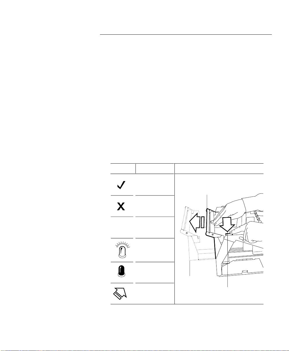
The following illustration provides an example of the explanations
given above.
Symbol
Definition
Correct
Incorrect
Not required
Example
is to be performed.
2
1
x
Light
Dark
position of outlined object
Direction/motion
P77 ATM - Operator Manual ix
sequence and direction/motion.
Page 10

About This Document
Guide To Illustrations Used In This Manual
x P77 ATM - Operator Manual
Page 11

Table of Contents
Contents
About This Document
Purpose And Audience .........................................................................vii
What This Manual Contains............................................................... viii
Guide To Illustrations Used In This Manual.......................................ix
Chapter 1
An Introduction To The Personas 77
What is the P77 ......................................................................................1-1
Module Location....................................................................................1-3
Chapter 2
Getting Started
Opening/Closing The Exterior Of The P77 .......................................2-1
Top Cabinet - Opening ....................................................................2-1
Top Cabinet - Closing ......................................................................2-3
Security Enclosure - Opening.........................................................2-4
Security Enclosure - Closing...........................................................2-5
Switching Power On/Off.....................................................................2-6
Mains Power Switch.........................................................................2-6
Security Enclosure Interlock Switch ..............................................2-7
Entering Supervisor Mode...................................................................2-8
Manually............................................................................................2-8
Auto-Supervisor ...............................................................................2-9
Opening/Closing The Standard Security Enclosure .....................2-10
Lock Types.......................................................................................2-10
Keylocks...........................................................................................2-12
Combination Locks ............................................................. ...... .....2-12
P77 ATM - Operator Manual
xi
Page 12

Table of Contents
Security Enclosures with Controlled Access Electronic Lock ...... 2-15
Opening the Mas-Hamilton Lock................................................2-15
Closing the Mas-Hamilton Lock..................................................2-18
Activating The Mas-Hamilton Lock.................................................2-19
Mas-Hamilton Documentation ....................................................2-22
Front Operator Interface....................................................................2-23
Operator Panel................................................................................2 -23
State of Health Messages...............................................................2-24
Running a Program............................................................ ............2-24
Volume Control..............................................................................2-24
Hardware Reset...................................................................................2 -25
Inserting/Removing Diskettes..........................................................2 -26
Inserting/Removing Compact Disks............................................... 2-28
Chapter 3
Error Reporting
Error Reporting - Using State Of Health ........................................... 3-1
How Errors In The PC Module Are Reported..................................3-3
Error Reporting - Using OES Codes...................................................3-5
The OES Codes.................................................................................3-5
Chapter 4
Currency Dispenser
Replenishing Currency Cassettes....................................................... 4-1
Emptying The Currency Purge/Reject Bin.............. ..... ...... ..............4-3
Clearing Jams - Bunch Dispenser .......................................................4-5
Chapter 5
Receipt Printer
Replenishing Paper............................................................................... 5-1
Clearing Jams.................................................... ...... ...............................5-6
xii P77 ATM - Operator Manual
Page 13

Table of Contents
Chapter 6
Journal Printer
Replenishing Paper - Graphics Printer...............................................6-1
Clearing Jams - Graphics Printer ................................ ...... ................6-13
Chapter 7
Maintenance
What Is Required To Maintain The P77? ...........................................7-1
Daily Tasks ........................................................................................ 7-1
Weekly Tasks..................................................................................... 7-1
Emptying the Dip Reader Debris Bin............................................7-1
Replenishment ..................................................................................7-1
Cleaning Kit.................................. ..........................................................7-2
Looking After The P77..........................................................................7-3
Weekly Maintenance Procedures ...................................................7-3
Cleaning the Facia and Exterior Panels......................................... 7-3
Cleaning Magnetic Heads on Dip Card Readers.........................7-4
Printer Media Storage...........................................................................7-5
Index
Index ...............................................................................................Index-1
User Feedback Form
P77 ATM - Operator Manual xiii
Page 14

Table of Contents
xiv P77 ATM - Operator Manual
Page 15

Table of Contents
An Introduction To The Personas 77
Chapter 1
An Introduction To The Personas 77
What is the P77 1- 1
Module Location 1-3
P77 ATM - Operator Manual
Page 16

Table of Contents
An Introduction To The Personas 77
P77 ATM - Operator Manual
Page 17

An Introduction To The Personas 77
What is the P77
A
What is the P77
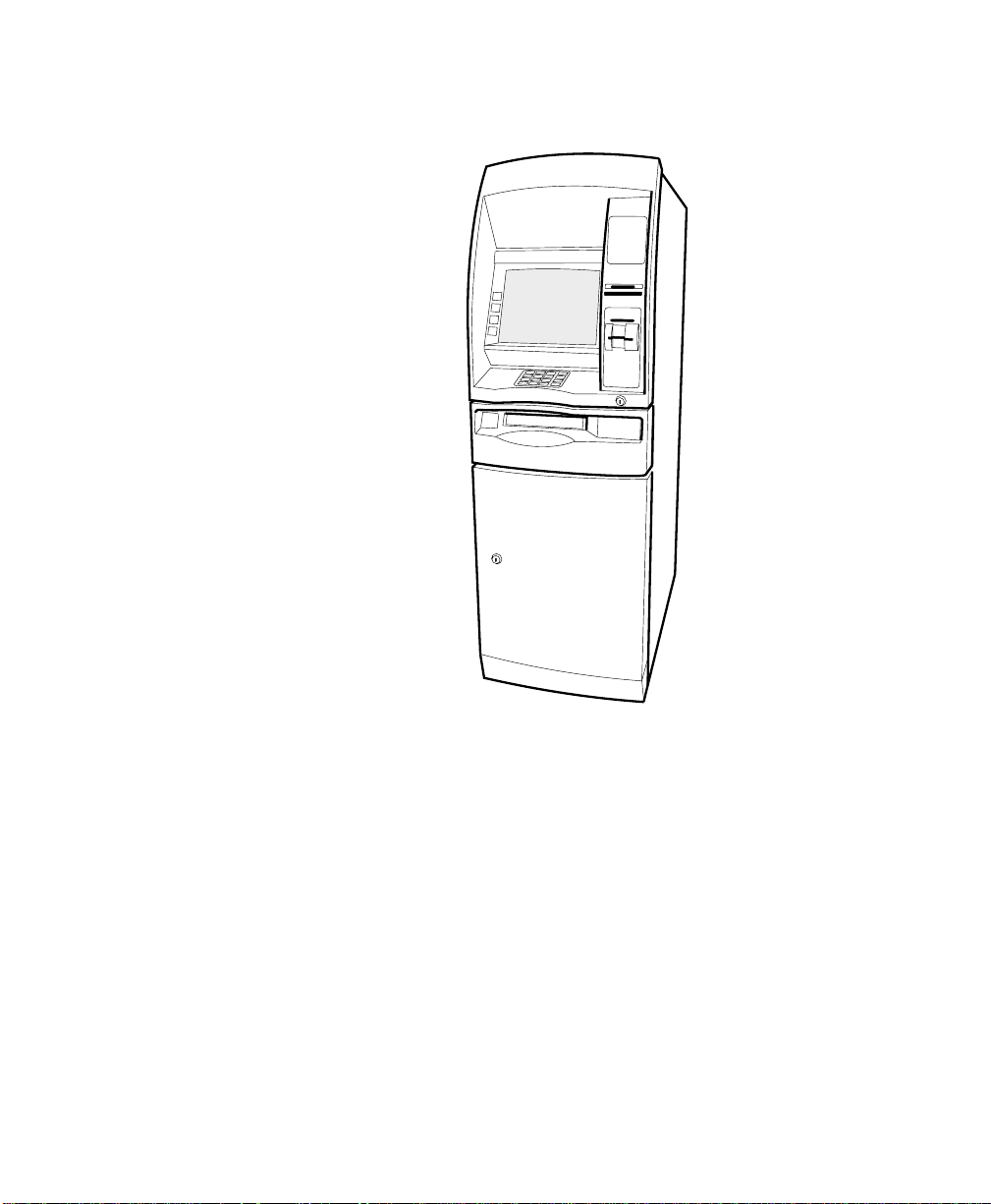
The NCR 5877 Personas ATM (P77) is a PC-bas ed self service ATM.
The heart of the P77 is a PC, running self-service application
software. This self-service application software manages
transactions and controls the various devices, such as printers, card
readers, monitor screens and keyb oards.
The P77 is designed to aid customers by automating the following
services:
Cash dispensing
●
Account transaction
●
Transfers
●
Order cheque book
●
Account enquiries
●
Account balance
●
Next loan payment
●
Credit card limit
●
Interest rates
●
Receipt printing
●
Mini-statement printing
●
Coupon printin g.
●
1
The P77 is a freestanding ATM that is serviced and replenished
from the front.
1
-1P77 ATM - Operator Manual
Page 18
An Introduction To The Personas 77
What is the P77
P77 With Bunch Presenter
1-2 P77 ATM - Operator Manual
Page 19
An Introduction To The Personas 77
Module Location
Module Location
The external and internal loca tions of the modules which comprise
the P77 are shown in the following illustrations.
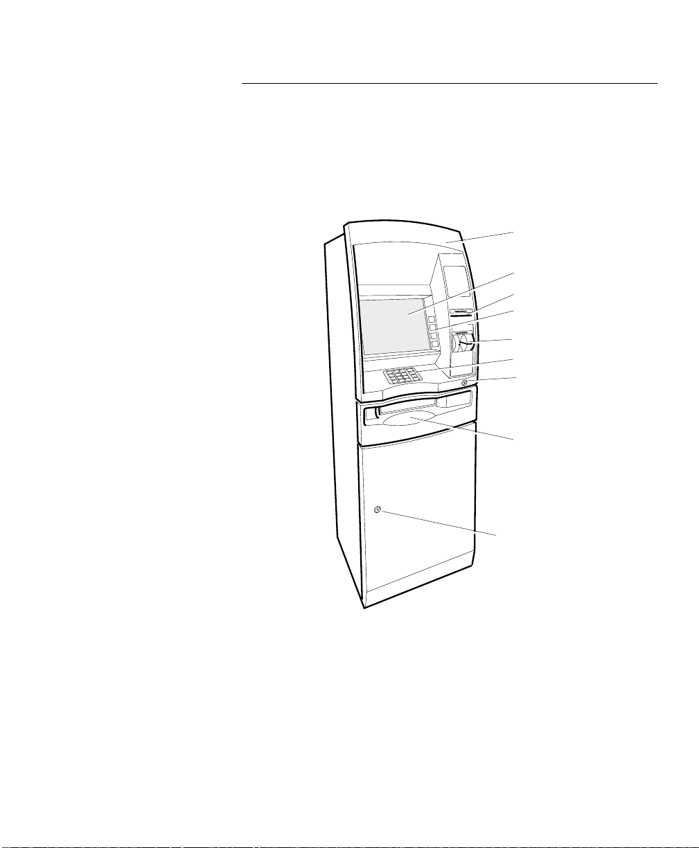
External Location
Facia
Display/Touchscreen
Receipt Printer
Functional
Display Keys
Dip Card Reader
Keyboard
Top Lock
Dispenser
1
Keylock
P77 ATM - Operator Manual 1-3
Page 20
An Introduction To The Personas 77
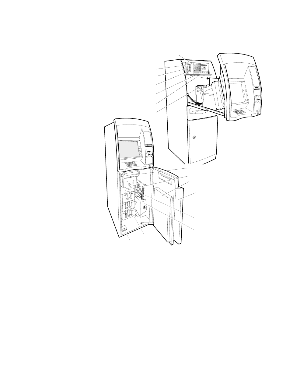
Module Location
Internal Location
Supervisor/Operator
Floppy Disk
Drive
On/Off Switch
CD Rom
Panel
Receipt Printer
Journal Printer
PC Core
Currency
Dispenser
Purge Bin
Security Enclosure
Door
Cabinet Front
Door
Currency
Cassette
Interlock
Switches
1-4 P77 ATM - Operator Manual
I/O Panel
Power Supply
Page 21

Table of Contents
Getting Started
Chapter 2
Getting Started
Opening/Closing The Exterior Of The P77 2-1
Top Cabinet - Opening 2-1
Top Cabinet - Closing 2-3
Security Enclosure - Opening 2-4
Security Enclosure - Closing 2-5
Switching Power On/Off 2-6
Mains Power Switch 2-6
Security Enclosure Interlock Switch 2-7
Entering Supervisor Mode 2-8
Manually 2-8
Auto-Supervisor 2-9
Opening/Closing The Standard Security Enclosure 2-10
Lock Types 2-10
Primary Lock Types: 2-10
Secondary Lock Types: 2-10
Position of Primar y and Secondary Loc ks 2-11
Opening Sequence of the Primary and Secondary Locks 2-11
Keylocks 2-12
Unlock A Keylock 2-12
Lock A Keylock 2-12
Combination Locks 2-12
Factory Set Combination - Unlocking 2-13
Customer Set Combination - Unlocking 2-14
Combination Lock - Locking 2-14
Combination - Chang in g 2-14
P77 ATM - Operator Manual
Page 22

Table of Contents
Getting Started
Security Enclosures with Controlled Access Electronic Lock 2-15
Opening the Mas-Hamilton Lock 2-15
Closing the Mas-Hamilton Lock 2-18
Activating The Mas-Hamilton Lock 2-19
Mas-Hamilton Documentation 2-22
Front Operator Interface 2-23
Operator Panel 2-23
State of Health Messages 2-24
Running a Program 2-24
Volume Control 2-24
Hardware Reset 2-25
Inserting/Removing Diskettes 2-26
Standard Enclosure 2-26
Standard Enclosure 2-27
Inserting/Removing Compact Disks 2-28
P77 ATM - Operator Manual
Page 23
Getting Started
Opening/Closi ng The Exterior Of The P77
Opening/Closing The Exterior Of
B
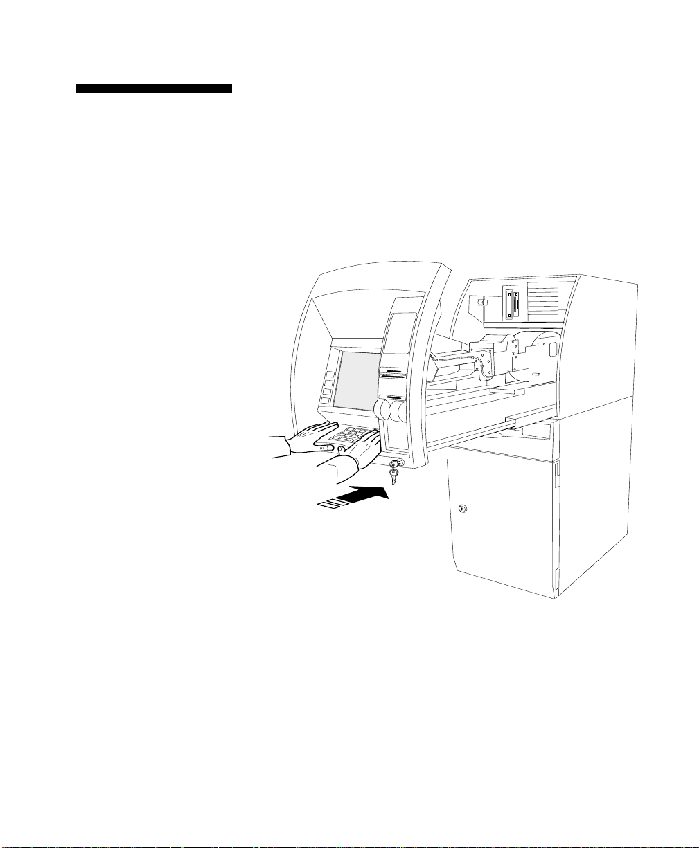
Top Cabinet Opening
The P77
The top cabinet and security enclosure of the P77 can be opened
independently of each other. This enables the consumables in the
top cabinet to be replenished without compromising the security of
the cash dispenser.
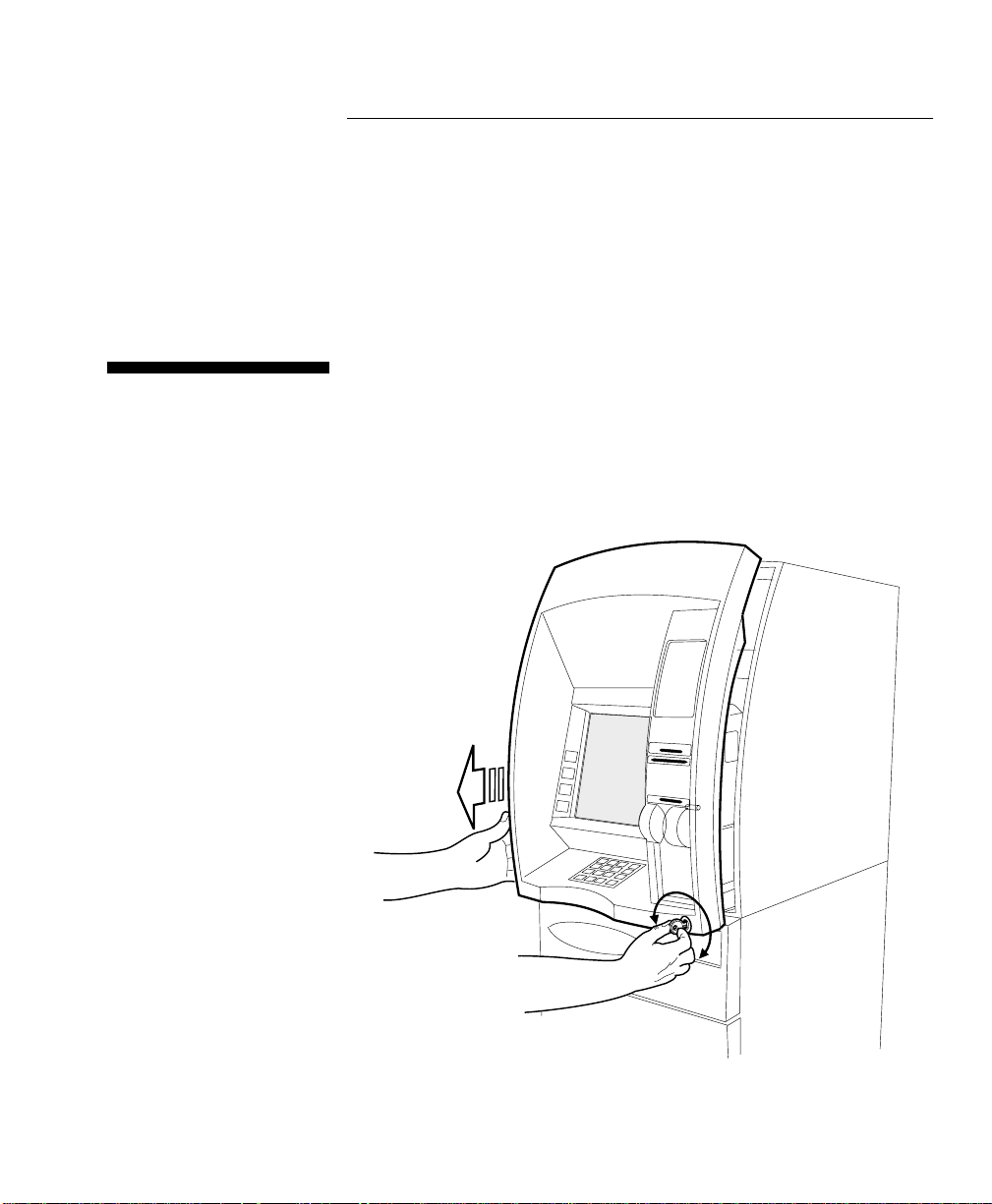
Open the top cabinet as follows:
1 Insert the key, in the facia lock.
2
2 Turn (in either direction) and hold the key to open the lock.
3 Using one hand, pull the facia forwards.
4 Release the key.
2
2
-1P77 ATM - Operator Manual
Page 24
Getting Started
Opening/Closing The Exterior Of The P77
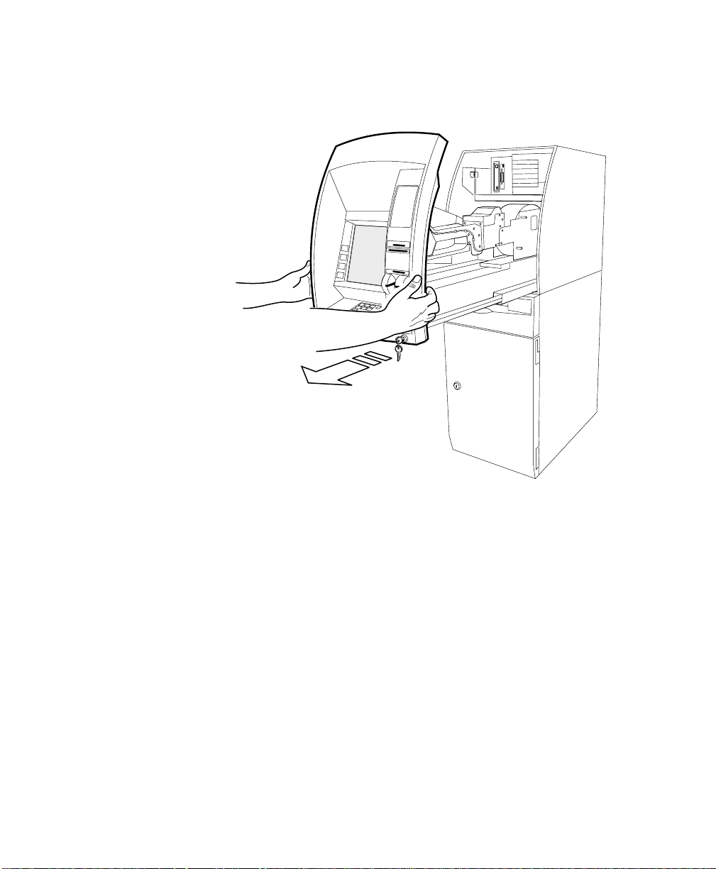
5 Using both hands, carefully pull the facia out of the top cabinet
until the slides are fully extended.
2-2 P77 ATM - Operator Manual
Page 25
Top Cabinet Closing
Getting Started
Opening/Closi ng The Exterior Of The P77
Close the top cabinet as follows:
2
Caution Do not grip the facia when closing the top cabinet.
1 With your hands flat, either side of the keypad, push the facia
into the top cabinet until the lock locks.
2 Remove the key.
P77 ATM - Operator Manual 2-3
Page 26
Getting Started
Opening/Closing The Exterior Of The P77
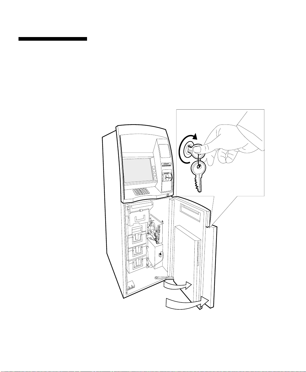
Open the security enclosure as follows:
Security Enclosure Opening
1 Insert the key, in the cabinet lock, and turn it clockwise.
2
2 Open the cabinet door.
3 Unlock the safe door, in accordance with the relevant
4 Open the safe door.
instructions detailed under “Open/Closing The Standard
Security Enclosure” for the configuration of your P77.
2-4 P77 ATM - Operator Manual
Page 27

Security Enclosure Closing
Getting Started
Opening/Closi ng The Exterior Of The P77
Closing the security enclosure as follows:
1 Close and lock the security enclosure door in accordance with
2
the relevant instructions detailed under “Open/Closing The
Standard Security Enclosure” for the configuration of your P77.
2 Close the cabinet door.
3 Turn the key counter-clockwise and remove the key.
P77 ATM - Operator Manual 2-5
Page 28

Getting Started
Switching Power On/Off
Mains Power Switch
Switching Power On/Off
There are two power switches fitted to the P77:
Mains Power Switch - switches mains power On/Off.
●
Security Enclosure Interlock Switch - switches power, to the
●
cash dispenser located inside the security enclosure, On/O ff.
To switch the mains power, to the P 77 , On/Off, proceed as follows:
2
1 Open the top cabinet.
2 Press the orange switch to the required position:
on (pressed in at the “1” side)
●
off (pressed in at the “0” side).
●
2
1
0
3 Close the top cabinet.
2-6 P77 ATM - Operator Manual
Page 29
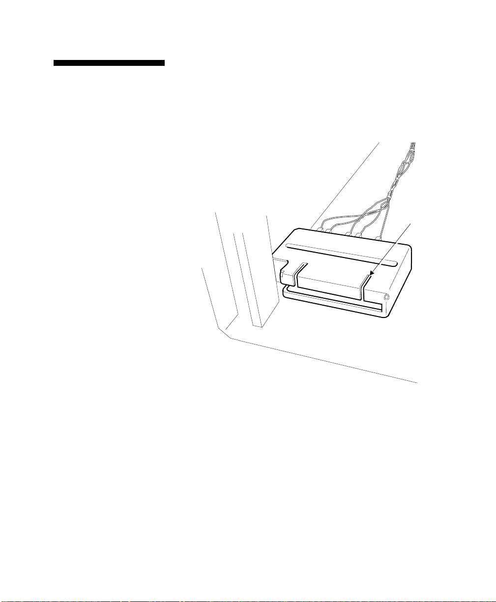
Security Enclosure Interlock Switch
Getting Started
Switching Power On/Off
When the safe door is opened, power to the cash dispenser is
switched off by an isolator switch. The dispenser isolator switch is
2
located, behind a cover, on the bottom of the safe.
Note: power is automatically restored to the cash dispenser when
the safe door is closed.
Dispenser
Interlock
P77 ATM - Operator Manual 2-7
Page 30
Getting Started
Entering Supervisor Mode
Manually
Entering Supervisor Mode
Entering Supervisor Mode depends on whether you are accessing
the top cabinet or the security enclosure of the P77:
top cabinet - manually
●
security enclosure - automatically.
●
When you access the top cabine t of the P77, you will have to enter
2
Supervisor Mode manually:
1 Open the top cabinet.
2 Press the Normal/Supervisor switch, on the operator panel, to
the Supervisor position.
2
AL
NORM
3 After you have completed the task, press the
Normal/Supervisor switch to the Normal position.
4 Close and lock the top cabinet.
2-8 P77 ATM - Operator Manual
SUPERVISOR
Page 31

Auto-Supervisor
Getting Started
Entering Supervisor Mode
The P77 is fitted with an Auto-Supervisor facility. However, this
2
only applies when accessing the security enclosure. The P77 will
automatically enter Supervisor Mode when the safe door is opened.
When the safe door is closed, the P77 automatically returns to the
Normal Mode.
The supervisor interlock switch is located behin d a cov er, on the
bottom of the safe.
Supervisor
Interlock
P77 ATM - Operator Manual 2-9
Page 32

Getting Started
Opening/Closing The Standard Security Enclosure
Opening/Closing The Standard
Lock Types
Security Enclosure
The standard security enclosure door will have a locking handle
plus either:
one lock (primary) or,
●
two locks (primary and secondary).
●
The make of lock (Standard, or Sargent and Greenleaf) fitted
depends on the configuration of the P77. The procedures for
opening and closing the various types of lock are the same for both
makes.
The possible lock types for primary and secondary locks are as
2
follows:
Primary Lock Types:
Key Lock Standard
●
Combination Lock Standard
●
Combination / Key Lock Standard
●
Mas-Hamilton Lock w/shunt Buy Lock No FLM
●
Mas-Hamilton Lock w/shunt Buy Lock In FLM Price
●
Secondary Lock Types:
Key Lock Standard
●
Combination Lock Standard
●
2
2
2
2-10 P77 ATM - Operator Manual
Page 33

Getting Started
Opening/Closin g T he S tandard Security Enclosure
Position of Primary and Secondary Locks
The following illustrations show the relative positions of primary
and secondary locks.
Primary Lock
0
10
90
80
70
Locking Handle
Secondary Lock
20
30
40
60
50
0
10
90
80
70
20
30
40
60
50
Opening Sequence of the Primary and Secondary Locks
2
2
If the P77 has a primary and a secondary lock fitted, the opening
sequence is as follows:
1 Unlock the secondary lock.
2 Unlock the primary lock.
3 Use the handle to retract the bolt and open the safe door.
Closing Sequence of the Primary and Secondary Locks
The primary and secondary locks must be locked in the fo llowing
sequence:
1 Close the door and use the handle to operate the bolt.
2 Lock the primary lock.
3 Lock the secondary lock.
P77 ATM - Operator Manual 2-11
Page 34

Getting Started
Opening/Closing The Standard Security Enclosure
The pair of keylock keys supplied with the P77 have been pre-cut to
Keylocks
2
a random factory-set combination. If one key should get lost, a new
pair of keys should be obtained and the keylock setting
changed..Refer to NCR publication, ATM Field Service Information
(SAMM) FM0547, Chapter 20, for details.
Combination Locks
Unlock A Keylock
To unlock a keylock, insert the key into the lock and turn it
clockwise as far as it will turn.
Lock A Keylock
To lock a keylock, turn the key counter-clockwise as far as it will
turn and then remove the key.
Three variants of combination lock may be fitted to the P77:
2
basic combination lock
●
combination lock with a keylock fitted in it
●
combinatio n lo c k wi t h a sile n t alarm option.
●
All the variants of the combination lock are three-number
combination locks.
The locks are precision locks, therefore, extreme care must be taken
to align combination numbers with the index.
Turn the dial slowly and steadily. If, after turning the dial the
correct number of revolutions, any number is turned beyond the
index, the entire series of combination numbers must be re-dialled.
Do not turn the dial back to regain a proper alignment of the
number and index, because each time a selected number is aligned
with the index a revolution is counted.
2
2
The procedures for unlocking and changing the combination on a
combination lock are the same regardless of whether the lock is a
primary or secondary lock.
2-12 P77 ATM - Operator Manual
Page 35

Changing Index
Getting Started
Opening/Closin g T he S tandard Security Enclosure
Opening Index
0
90
80
70
60
10
20
Dial
30
40
50
Factory Set Combination - Unlocking
If the combination lock is set at the original factory setting of 50,
unlock it as follows, dialling on the opening index:
1 If a keylock is fitted to the combination lock, insert the key into
the lock and turn it clockwise.
2 Turn the dial a minimum of four turns counter-clockwise and
stop on 50.
3 Tu rn the dial sl ow ly cl ock w ise u nti l the bo lt ret ract s. The loc k is
now open. Use the handle on the door to retract the door bolt
and open the door.
2
P77 ATM - Operator Manual 2-13
Page 36

Getting Started
Opening/Closing The Standard Security Enclosure
Customer Set Combination - Unlocking
If the combina t ion has been set at a three-number comb i nation, for
example 36-82-44, unlock it as follows:
1 If a keylock is fitted to the combination lock, insert the key into
the lock and turn it clockwise.
2 Turn the dial counter-clockwise, passing the first number (36)
three times, stop on the first number (36) the fourth time.
3 Turn the dial clockwise, passing the second number (82) twice,
and stop on the second number (82) the third time.
4 Turn the dial counter-clockwise, passing the third number (44)
once, and stop on the thir d number (44) the second time.
5 Turn the dial clockwise until the bolt retracts. The lock is now
open. Use the handle on the door to retract the door bolt and
open the door.
Combination Lock - Locking
To lock the combination lock, turn the dial at least four complete
turns counter-clockwise. If a keylock is fitted to the combination
lock, turn the dial until 0 is in line with the opening index and then
turn the key counter-clockwise and remove it from the lock.
Combination - Changing
Detailed instructions on how to change the co mbination of a lock
are inside the security enclosure.
2
2
2
2-14 P77 ATM - Operator Manual
Page 37

Getting Started
Security Enclosures with Controlled Access Electronic Lock
Security Enclosures with Controlled
Opening the MasHamilton Lock
Access Electronic Lock
This section describes how to operate the Mas-Hamilton lock to gain
access to the security enclosure of the P77.
Note: Before the Mas-Hamilton lock can be operated, it must be
activated. Refer to “Activating the Mas-Hamilton Lock”
Before the Mas-Humiliation lock can be operated, the following are
required:
2
a Personal Identifier key (PI key) - issued by the Key
●
Management Cent r e ( KMC)
a 6-digit access code - obtained from the KMC.
●
Keypad
LCD
5
4
1
3
2
8
0
9
7
EC
6
Home Position
*
#
2
Key Reader
Knob
(Opening/Closing)
P77 ATM - Operator Manual 2-15
Page 38

Getting Started
Security Enclosures with Controlled Access Electronic Lock
To open the Mas-Hamilton lock, proceed as follows:
1 Phone the KMC
2 Give requested details to verify identity to the KMC.
3 Take note of the 6-digit access code (three pairs of two),
allocated by the KMC.
4 Unlock and open the exterior of the 5877.
5 Spin the opening/closing knob of the lock counter clockwise,
this charges the lock, until EC is displayed on the LCD.
Note: If DL (Dial Left) is displayed, you must only turn the
opening/closing knob to the left (counter cloc kwise).
6 Turn the opening/closing knob to the home position.
7 Enter the 6-digit access code provided by the KMC.
8 IPI should be displayed on the LCD.
2-16 P77 ATM - Operator Manual
Page 39

Getting Started
Security Enclosures with Controlled Access Electronic Lock
9 Hold the PI key against the key reader to charge the PI key:
Keypad
5
4
3
7
0
9
8
Key Reader
Key
LCD
*
#
EC
2
1
6
Knob
(Opening/Closing)
10 If the correct 6-digit code has been entered and a valid PI key
has been pressed against the key reader, OPr will be displayed
on the LCD.
Note: If an incorrect code/PI key is used or there was a bad PI
key contact, a lightning bolt will be displayed on the LCD,
indicating an error condition. If it was a bad PI key contact,
YOU HAVE ONE MORE ATTEMPT AT OPENING THE
LOCK. If the error condition occurs after the 2nd attempt,
contact the KMC immediately.
11 Turn the opening/closing knob a quarter turn (90 degrees)
clockwise to release the bolt.
12 Open the safe door.
P77 ATM - Operator Manual 2-17
Page 40

Getting Started
Security Enclosures with Controlled Access Electronic Lock
To close the Mas-Hamilton lock, proceed as follows:
Closing the MasHamilton Lock
1 Close the safe door.
2
2 Spin the opening/closing knob counter clockwise to activate the
bolt and charge the lock until IPI is displayed on the LCD.
3 Hold the PI key against the key reader.
4 A unique 4-digit close code will be displayed. All locks are
closed.
Note: Take a note of the close code as it is required by the KMC
(Step 6).
5 Close the exterior of the 5877 and remove the key.
6 Phone the KMC.
Note: Ensure that the lock/doors on the 5877 are locked/closed
before contacting the KMC.
7 Verify identification
8 Provide the 4-digit close code to the KMC.
9 The KMC will inform you that either the code is correct or give
you the correct procedure to follow if the close code in wrong.
2-18 P77 ATM - Operator Manual
Page 41

Getting Started
Activating The Mas-Hamilton Lock
Activating The Mas-Hamilton Lock
Activating the Mas-Hamilton Lock requires a coordinated effort
between a Dispatcher at the Key Management Centre (KMC) and
First Line Maintenance (FLM) or Route person (the term FL M w ill
be used throughout the following instru ctions).
Note: The Mas-Hamilton lock may be in more than one mode at a
time, which means that sometimes the Mas-Hamilton lock will
already be activated in one mode when you want to activate it in
another.
Keypad
LCD
5
4
1
3
2
8
0
9
7
EC
6
Home Position
*
#
2
Key Reader
B
Knob
(Opening/Closing)
P77 ATM - Operator Manual 2-19
Page 42

Getting Started
Activating The Mas-Hamilton Lock
The roles of the Dispatcher and FLM personnel are as follows:
Dispatcher - activates:
●
the Mas-Hamilton lock in the program
●
and the Supervisor Audit (SA) key.
●
FLM person physically goes to the Mas-Hamilton lock on the
●
P77 to complete the activation where he/she will need the
following:
the initialized SA key
●
a Personal Identifier (PI) key
●
a Change key
●
a combination from the Dispatcher.
●
A Change key is required for this procedure. The Change key will
normally be in the possession of the F LM person. The Change key
has two prongs that, when extended, fit securely into the change
key socket on the back of the Mas-Hamilton lock. Any Cencon
Change key may be used in any Cencon Mas-Hamilton lock. The
Change key is not encoded or unique in any way.
Activate the Mas-Hamilton lock as foll ows:
1 Open the Mas-Hamilton lock using the factory combination (50-
25-50). Refer “Opening The Master Lock” and open the safe
door.
Caution Do not close the safe door at any time during this procedure until
Step 15.
Note: If the Mas-Hamilton lock is already in one mode and you
are activating another, someone who has the authority to open
the Mas-Hamilton lock will have to be at the P77.
2 Extend the prongs of the Change key and insert it into the
change key socket on the back of the Mas-Hamilton lock while
OPr is displayed.
3 Power the lock by turning the opening/closing knob counter
clockwise. The Change key symbol will be shown in the
display window.
2-20 P77 ATM - Operator Manual
Page 43

Getting Started
Activating The Mas-Hamilton Lock
4 Ent er the factory combination 50 25 50.
5 After the factory combination has been correctly entered, the
ISA symbol will be displayed. Hold the SA key against the MasHamilton lock’s key reader until POC is displayed.
Note: The InI symbol will be temporarily displayed before POC
is displayed.
6 Remove the Change key (from the Mas-Hamilton lock’s socket)
and SA key (from the Mas-Hamilton lock’s key reader).
7 OPr should be displayed. Turn the opening/closing knob
clockwise to retract the bolt of the Mas-Hamilton lock.
8 Open the safe door.
9 Keeping the safe door open, close the Mas-Hamilton lock.
10 Turn the opening/closing knob counter clockwise, to activate
the bolt and charge the Mas-Hamilton lock, until EC is
displayed.
11 Turn the opening/closing knob to the home position.
12 Enter the dispatched combination.
13 IPI should be displayed. Insert the F LM key (PI key)
14 OPr should be displayed. Turn the opening/closing knob
clockwise to retract the bolt of the Mas-Hamilton lock.
15 Close the safe door and lock it by turning the opening/closing
knob counter clockwise.
16 Power the lock by turning the opening/closing knob counter
clockwise.
17 When the display prompts, IPI, insert the FLM key (PI key) that
was used to open the Mas-Hamilton lock when you started the
activation proced ur e .
18 The display will then show the Close Seal Number (* cxx then
xx) for the first opening, which must be relayed back to the
Dispatcher.
Note: * Where x is a number. Take note of the two sets of 2digits that will be displayed.
P77 ATM - Operator Manual 2-21
Page 44

Getting Started
Activating The Mas-Hamilton Lock
Mas-Hamilton Documentation
2
Further details of how to set up and manage the Mas-Hamilton lock
operations are detailed in the following Mas-Hamilton Group
publications:
CENCON System 2000 Access Control System
●
Getting Started Guide
●
Supervisor Guide
●
Special Su p e rv isor Guide
●
FLM Dispatcher Guide
●
Route Dispatcher Guide
●
CENCON 2000 Syst e m Guide.
●
These publications can be purchased from the following Order
Point:
Mas-Hamilton Gr oup
805-D Newtown Circle
LEXINGTON
Kentucky
40511-1240
Tel: (1) 606 253-4744
Fax: (1) 606 253-4748
For the attention of Customer Service Manager
2-22 P77 ATM - Operator Manual
Page 45

Getting Started
Front Operator Interface
Operator Panel
Front Operator Interface
Depending on the configuration of the P77, the operator panel is
2
used in conjunction with the cardholder display, (may be a touch
screen), the Function Display Keys (FDKs) and the cardholder
keyboard to display any error messages or State Of Health (SOH)
messages, and to access the various Supervisor Mode programs
described in the NCR publication, Self Service Terminal Supervisor
Functions Manual (B006-0000-4718).
2
NORMAL
SUPERVISOR
COMM
RESET
P77 ATM - Operator Manual 2-23
Page 46

Getting Started
Front Operator Interface
State of Health Messages
Running a Program
Volume Control
The switches and indicator on the front operator panel are:
Switch /Indicator Description
Normal /Super visor
Switch
Used to ente r the Supervisor Mode and return to
Normal Mode
Comms Indicator Flashes to indicate that the P77 is communicating
with a host system.
Reset Switch When pressed, cause a reset of the whole P77.
State of Health (SOH) messages, if any, will be displayed, on the
cardholder display, when the P77 enters the Supervisor Mode.
2
To run a progra m from any of the menus whic h ca n be displayed,
2
press the key on the cardholder keyboard which corresponds to the
number of the program you wish to run, or use the Function
Display Key (FDK) alongside the cardholder display, or touch the
appropriate area on the touch screen.
The volume control knob, for digital audio, is located to the left of
2
the PC Core. Volume can also be controlled through the application.
2-24 P77 ATM - Operator Manual
Page 47

Getting Started
Hardware Reset
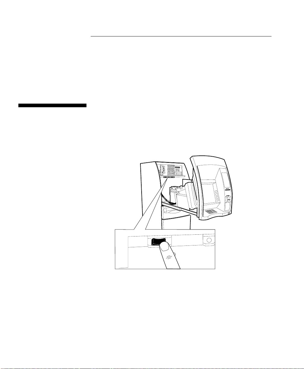
Hardware Reset
A Reset switch is provided on the operator panel. When the Reset
switch is pressed, the P77 executes its diagnostic procedures,
reloads the system software and initialises the user application
program.
To reset the P77, proceed as follows:
1 Open the top cabinet.
2 Pr e s s th e Re set switch on the ope r at or panel.
2
RESET
3 Close and lock the top cabinet.
Note: After the P77 is reset, several minutes will elapse before the
software is loaded and the application is displayed.
P77 ATM - Operator Manual 2-25
Page 48

Getting Started
Inserting/Removing Diskettes
Inserting/Removing Diskettes
To insert or remove a diskettes from the disk drive proceed as
follows.
1 Open the top cabinet.
2 If necessary, press in the button shown below to eject the
current diskette from the disk drive. Remove the diskette.
Standard Enclosure
2
2
2-26 P77 ATM - Operator Manual
Page 49

Inserting/Removing Disk ettes
3 Insert the new diskette into the disk drive as shown.
Getting Started
Standard Enclosure
4 Close and lock the top cabinet.
2
P77 ATM - Operator Manual 2-27
Page 50

Getting Started
Inserting/Removing Compact Disks
Inserting/Removing Compact Disks
To insert or remove a Compact Disk (CD) from the disk drive
proceed as follows.
1 Open the top cabinet.
2 Press the button shown below to open the disk tray and, if
necessary, remove the current CD.
2
3 Insert the new CD with the printed side facing to the left.
Ensure that the tabs at the bottom of the tray, are holding the
disk in position.
2-28 P77 ATM - Operator Manual
Page 51

Getting Started
Inserting/Removing Compact Disks
4 Either, re-press the button, or lightly push the end of the tray
inwards until it retracts automatically.
5 Close and lock the top cabinet.
P77 ATM - Operator Manual 2-29
Page 52

Getting Started
Inserting/Removing Compact Disks
2-30 P77 ATM - Operator Manual
Page 53

Table of Contents
Error Reporting
Chapter 3
Error Reporting
Error Reporting - Using State Of Health 3-1
How Errors In The PC Module Are Reported 3-3
Error Reporting - Using OES Codes 3-5
The OES Codes 3-5
OES Codes - Structure 3-5
OES Codes 3-6
OES Codes - Qualifier Cod e s 3-6
P77 ATM - Operator Manual
Page 54

Table of Contents
Error Reporting
P77 ATM - Operator Manual
Page 55

Error Reporting
Error Reporting - Using State Of Health
Error Reporting - Using State Of
C
Health
The P77 may use an error reporting system called State Of Health
(SOH) reporting. SOH reporting is designed to tell you how
“healthy” your P77 is. In addition to reporting error conditions, it
also reports when a module requires to be replenished or replaced.
To view SOH messages, either:
open the top cabinet of the P77 and press the
●
Normal/Supervisor switch, on the operator panel, to the
Supervisor position, or
open the security enclosure of the P77 - auto-supervisor will be
●
activated.
The P77 will enter Supervisor Mode and display SOH messages on
the screen.
If all the modules in your P77 are healthy (no module requires to be
replenished or replaced) a TERMINAL HEALTHY messag e will be
displayed. If any module requires attention, a message stating the
module name and a description of the problem is displayed. If there
is more than one message, each message will be displayed in turn
for a few seconds.
The 4-digit number which appears alongside the SOH message is a
message identification number. If you have to call a service
engineer at any time, quote the SOH message identification number
as well as the message text.
3
The asterisks (*) indicate the skill level required to fix whatever
problem is generating the current SOH message, and also indicate
which VERIFY SOH option (see NCR publication, Self Service
Terminal Supervisor Functions Manual, B006-0000-4718) should be
selected to clear the SOH message.
3
-1P77 ATM - Operator Manual
Page 56

Error Reporting
Error Reporting - Using State Of Health
Some SOH messages require to be acted upon immediately, others
indicate you should be prepared to carry out a replenishment/
replacement procedure in the near future. If required, use the
relevant VERIFY SOH option as described in the Supervisor Manual
to clear the SOH message.
Note: If a SOH message is displayed which indicates that a module,
needs to be replaced, you should contact your local service centre.
3-2 P77 ATM - Operator Manual
Page 57

Error Reporting
How Errors In The PC Module Are Reported
How Errors In The PC Module Are
Reported
The SOH reporting system does not report on the operator panel if a
fault has occurred on one of the boards in the PC module.
The boards in the PC module are tested during power-up and at
reset. If a fault is detected on one of the components of the PC
module, the SOH Light Emitting Diode (LED) will be illuminated
red. Following is a summary of the LED colour code.
LED Colour Description
Amber Test Still Executing
Red Test Failed
Green Test Passed
Unlit No Power To Module
3
P77 ATM - Operator Manual 3-3
Page 58

Error Reporting
How Errors In The PC Module Are Reported
The location of the LED, for the Pele board, is shown in the
following illustrations.
The LED for the Phantom board is located on the SSPA board.
3-4 P77 ATM - Operator Manual
Page 59

Error Reporting
Error Reporting - Using OES Codes
The OES Codes
Error Reporting - Using OES Codes
P77s which do not use the State of Health (SOH) reporting system
run applications which have been written to the migrated
Application Device Interface (ADI).
If your P77 does not use SOH reporting, it will use the same
Operational Exception Status (OES) code reporting as used in
previous generations of ATMs, for example the 5070 or the 5085.
When an exception condition is detected in any mod ule, an OE S is
reported and the OES code is displayed, identifying the module,
and specifying whether it is a replenishment requirement or a fault.
This OES code is the starting point of the standard fault finding
procedure, and the code can be decoded without access to the
interior of the P77, to establish the reason for the exception
condition, and the action to be taken.
When the P77 develops a problem or fault, a five character code is
3
displayed at the lower left-hand corner of the cardholder display. If
the P77 is in service, the code is displayed between transactions.
This is the OES code, the starting point for the operator establishin g
the cause of a problem.
OES Codes - Structure
3
3
The structure of the OES code is as follows:
1st three characters (refer “OES Codes” on next
page)
5th character (refer “Qualifier Codes” on
next page)
Examples:
CRD=F
JPT-E
P77 ATM - Operator Manual 3-5
Identify the module
Indicates whether the problem:
●
is hardware failure, or
●
needs media replenishment
MCRW module is faulty
Journal Printer is out of paper (empty)
Page 60

Error Reporting
Error Reporting - Using OES Codes
OES Codes
The OES codes are shown in the following tables:
Code Module
RPT Receipt Printer
JPT Journal Printer
DIS Currency Dispenser
CT1 Currency Cassette Type 1
CT2 Currency Cassette Type 2
CT3 Currency Cassette Type 3
CT4 Currency Cassette Type 4
CRD Magnetic card reader/writer
FD0 Flex Disk 0
DAS Door Access System
PHO Security Camera
ENC Encryptor
HOC High Order Communications
TOD Time-Of-Day Clock
NSD Nightsafe Depository
CKB Cardholder Keyboard
SYS System
3
OES Codes - Qualifier Codes
The OES qualifier codes are shown in the following table:
Qualifier Code Description of Problem
F Module Fatal
L Media Low
E Out of Media (empty)
O Bin overfill
3-6 P77 ATM - Operator Manual
3
Page 61

Table of Contents
Currency Dispenser
Chapter 4
Currency Dispenser
Replenishing Currency Cassettes 4-1
Emptying The Cu rr e n c y Pu r g e /Reject Bin 4-3
Clearing Jams - Bunch Dispenser 4-5
P77 ATM - Operator Manual
Page 62

Table of Contents
Currency Dispenser
P77 ATM - Operator Manual
Page 63

Currency Dispenser
Replenishing Currency Cass ettes
D
Replenishing Currency Cass ettes
To replenish the currency cassettes in your P77 proceed as follows:
1 Open the security enclosure.
2 Lift the catch on the right-hand side of the currency cassette
you wish to replenish and pull the cassette out of the P77.
4
4
-1P77 ATM - Operator Manual
Page 64

Currency Dispenser
Replenishing Currency Cassettes
3 If the cassette is to be sent to a secure area for refilling, do so in
accordance with your institute's rules. Refer to NCR publication
H-8015-STD1-01/02-08 Currency Cassette Owner's Manual, D11297-A for details of how to open and replenish the currency
cassette.
4 Push the full cassette firmly into the P77 until the cassette latch
clicks into place.
5 Repeat Steps 4, 5 and 6 for all casset t es wh ich require to be
replenished.
6 Close and lock the security enclosure.
7 Follow your in-house procedures for indicating that the
currency cassettes have been replenished.
4-2 P77 ATM - Operator Manual
Page 65

Emptying The Currency Purge/Reject Bin
Emptying The Currency
Currency Dispenser
Purge/Reject Bin
To empty the standard currency purge/reject bin in your P77,
proceed as follows:
1 Open the security enclosure.
4
P77 ATM - Operator Manual 4-3
Page 66

Currency Dispenser
Emptying The Currency Purge/Reject Bin
2 Lift the catch on the left-hand side of the bin and pull the bin out
of your P77.
3 Remove the currency from the bin.
4 Slide the empty bin into your P77 until it locks in place.
5 Close and lock the security enclosure.
6 Follow your in-house procedures for indicating that you have
emptied the currency purge/reject bin.
4-4 P77 ATM - Operator Manual
Page 67

Currency Dispenser
Clearing Jams - Bunch Dispenser
Clearing Jams - Bunch Dispenser
The indication of a currency dispenser jam wi ll be a State Of Health
(SOH) message.
To clear a currency jam proceed as follows:
1 Open the security enclosure.
2 Lift the currency dispenser catch, and use the green handle to
pull the currency dispenser out of the P77 until its slides are
fully extended.
4
P77 ATM - Operator Manual 4-5
Page 68

Currency Dispenser
Clearing Jams - Bunch Dispenser
3 The procedures for clearing a jam depend on the cause and
location of the jam. The SOH message will indicate where the
jam is.
If SOH indicates a bill jam at the pick sensor/ module, or a
●
gulp feed failure, go to Step 4.
If the SOH message indicates a bill jam in the main
●
transport, proceed to Step 7.
If the SOH message indicates a bill jam at sensor 2, proceed
●
to Step 9.
If the SOH message indicates a bill jam at sensor 1 or a
●
purge bin overfill, proceed to Step 11.
If the SOH message indicates a bill jam at sensor 4, 5, or 6
●
proceed to Step 14.
4-6 P77 ATM - Operator Manual
Page 69

Currency Dispenser
Clearing Jams - Bunch Dispenser
4 Bill jam at the pick sensor/module or a gulp feed failure - Lift
the green catch on the right-hand side of the currency cassette
indicated in the SOH message (cassette position 1 is the top
cassette) and pull the cassette out of the P77.
5 Reach inside the hole vacated by the cassette and remove any
jammed bills.
6 Push the cassette back into the P77 until the cassette catch clicks
into place. Proceed to Step 15.
P77 ATM - Operator Manual 4-7
Page 70

Currency Dispenser
Clearing Jams - Bunch Dispenser
7 Bill jam in the main tr ansport - Turn the pulley on the side of
the dispenser counter-clockwise until the bills enter the stacking
area.
4-8 P77 ATM - Operator Manual
Page 71

Currency Dispenser
Clearing Jams - Bunch Dispenser
8 Insert your hand through the hole in the side of the dispenser as
shown, and remove the bills. Proceed to Step15.
P77 ATM - Operator Manual 4-9
Page 72

Currency Dispenser
Clearing Jams - Bunch Dispenser
9 Bill jam at sensor 2 - Turn the large gear wheel on the side of
the dispenser until the clamp arm, indicated below, is in its up
position.
4-10 P77 ATM - Operator Manual
Page 73

Currency Dispenser
Clearing Jams - Bunch Dispenser
10 Insert your hand through the hole in the side of the dispenser as
shown, and remove the bills. Proceed to Step15.
P77 ATM - Operator Manual 4-11
Page 74

Currency Dispenser
Clearing Jams - Bunch Dispenser
11 Bill jam at sensor 1 - Lift the catch on the left-hand side of the
purge bin and pull the purge bin out of the dispenser.
4-12 P77 ATM - Operator Manual
Page 75

Currency Dispenser
Clearing Jams - Bunch Dispenser
12 Reach inside the hole vacated by the purge bin and remove any
jammed bills. If you cannot reach the bills, turn the drums
indicated below until the bills are in an accessible position and
then remove them.
13 Push the purge bin back into the P77 until it locks in place.
Proceed to Step 15.
P77 ATM - Operator Manual 4-13
Page 76

Currency Dispenser
Clearing Jams - Bunch Dispenser
14 Bill jam at sensor 4, 5 or 6 - If required, turn the drums in the
top of the transport until the bills are in an accessible position.
Reach into the transport and remove the bills.
15 Push the dispenser back into the P77.
16 Close and lock the security enclosure.
17 Follow your in-house procedures for indicating you have fixed,
without replacing, the faulty module in the currency dispenser.
4-14 P77 ATM - Operator Manual
Page 77

Table of Contents
Receipt Printer
Chapter 5
Receipt Printer
Replenishing Paper 5-1
Clearing Jams 5-6
P77 ATM - Operator Manual
Page 78

Table of Contents
Receipt Printer
P77 ATM - Operator Manual
Page 79

Receipt Printer
Replenishing P a pe r
E
Replenishi ng Paper
The paper used to replenish your printer must meet the
specification given in NCR publication Consumable Items For Self
Service, (B006-4992-0000).
To replace the printer paper proceed as follows:
1 Open the top cabinet.
2 Press the Normal/Supervisor switch, on the operator panel, to
the Supervisor position.
Receipt Printer
5
R
O
IS
V
R
E
P
U
L
A
M
R
O
N
S
5
-1P77 ATM - Operator Manual
Page 80

Receipt Printer
Replenishing Paper
3 Open the print mechanism cover using the green locking lever -
the cover will spring open.
4 Lift out the paper roll core, spindle and any remaining paper .
Pull out any paper from the paper entry slot. Discard the paper
roll core and any remaining paper, but retain the spindle.
5-2 P77 ATM - Operator Manual
Page 81

Receipt Printer
Replenishing P a pe r
5 Close the print mechanism cover - push it down until it clicks
shut.
6 Remove sufficient paper from the new supply roll so that no
traces of glue or tape remain on the roll. Tear off the end of the
supply roll to make a reasonably straight edge without creases.
7 Insert the spindle into the core of the new paper roll. Lower the
paper roll into the printer so that the spindle drops into the
slots. The paper feeds from the top of the roll.
Note: Graphical instructions are provided on the side of the
printer.
P77 ATM - Operator Manual 5-3
Page 82

Receipt Printer
Replenishing Paper
8 Manually guide the paper into the printer entry slot until it
stops - approximately 75 mm (3 in.).
5-4 P77 ATM - Operator Manual
Page 83

Receipt Printer
Replenishing P a pe r
9 Press the paper feed button and continue to feed in the paper
manually until it is gripped by the print mechanism. The printer
will automatically feed the paper through the printer, print a
test graphic and feed the receipt out of the transport.
10 Remove the receipt from the exit slot.
11 Follow your in-house procedures for indicating that the paper
has been replaced in the receipt printer.
12 Press the Normal/Supervisor switch, on the operator panel, to
the Normal position.
13 Close and lock the top cabinet.
P77 ATM - Operator Manual 5-5
Page 84

Receipt Printer
Clearing Jams
Clearing Jams
The indication of a receipt printer jam will be a State Of Health
message.
To clear a jam within the receipt printer, proceed as follows:
1 Open the top cabinet.
2 Press the Normal/Supervisor switch, on the operator panel, to
the Supervisor position.
3 Inspect the printer to see if you can identify the cause of the
paper jam.
4 Paper jammed at the exit slot - lift the plunger and slide the
printer backwards until clear of the exit slot.
5
5-6 P77 ATM - Operator Manual
Page 85

Receipt Printer
Clearing Jams
5 Remove any jammed paper from the exit slot/end of the
transport.
6 Lift the transport, to align it with the exit slot, and slide the
printer forwards until the plunger engages.
7 Check that the transport is engaged correctly with the exit slot.
P77 ATM - Operator Manual 5-7
Page 86

Receipt Printer
Clearing Jams
8 Paper jammed in the printer tra nspo rt - remove it carefully
using your fingers.
5-8 P77 ATM - Operator Manual
Page 87

Receipt Printer
Clearing Jams
9 Paper jammed under the printer cover - open the print
mechanism cover using the green locking lever - the cover wil l
spring open.
P77 ATM - Operator Manual 5-9
Page 88

Receipt Printer
Clearing Jams
10 Remove any torn or crumpled paper from under the cover.
11 Make sure that the receipt roll can turn freely by spinning the
paper roll away from the front of the printer. If the roll does not
turn freely, remove it from the printer and check that there are
no foreign objects preventing the paper roll from rotating.
12 If necessary, lower the paper roll into printer so that the spindle
drops into the slots. The paper feeds from the top of the roll.
5-10 P77 ATM - Operator Manual
Page 89

Receipt Printer
Clearing Jams
13 Close the print mechanism cover - push it down until it clicks.
14 If necessary, tear off the end of paper roll to make a reasonably
straight edge.
P77 ATM - Operator Manual 5-11
Page 90

Receipt Printer
Clearing Jams
15 Manually guide the paper roll into the printer entry slot until it
stops - approximately 75 mm (3 in.).
5-12 P77 ATM - Operator Manual
Page 91

Receipt Printer
Clearing Jams
16 Press the paper feed button and continue to feed in the paper
manually until it is gripped by the print mechanism. The printer
will automatically feed the paper through the printer, print a
test graphic and feed the receipt out of the transport.
17 Remove the receipt from the exit slot.
18 Follow your in-house procedures fo r indicating that a jam has
been cleared in the receipt printer.
19 Press the Normal/Supervisor switch, on the operator panel, to
the Normal position.
20 Close and lock the top cabinet.
P77 ATM - Operator Manual 5-13
Page 92

Receipt Printer
Clearing Jams
5-14 P77 ATM - Operator Manual
Page 93

Table of Contents
Journal Printer
Chapter 6
Journal Printer
Replenishing Paper - Graphics Printer 6-1
Clearing Jams - Graphics Printer 6-13
P77 ATM - Operator Manual
Page 94

Table of Contents
Journal Printer
P77 ATM - Operator Manual
Page 95

Replenishing Paper - Graphics Printer
Replenishing Paper - Graphics
Journal Printer
F
Printer
The paper used to replenish your printer must meet the
specification given in NCR publication Consum able Ite ms for Self
Service, B006 -00 00 -4992.
If your ATM is configured with Electronic Journal, refer to the NCR
publication NDC+ Super visor’s Reference Manu al, B006-0000-2487.
To replace the journal paper roll proceed as follows:
1 Open the top cabinet.
2 Press the Normal/Supervisor switch, on the operator panel, to
the Supervisor position.
6
NORMAL
SUPERVISOR
6
-1P77 ATM - Operator Manual
Page 96

Journal Printer
Replenishing Paper - Graphics Printer
3 If there is any paper left on the supply roll, press the paper feed
button to wind on a few turns of blank paper to protect the
printed journal roll.
6-2 P77 ATM - Operator Manual
Page 97

Journal Printer
Replenishing Paper - Graphics Printer
4 Remove the printed journal roll by pushing it up from
underneath. If necessary, tear off the paper against the serrated
cutter.
P77 ATM - Operator Manual 6-3
Page 98

Journal Printer
Replenishing Paper - Graphics Printer
5 Remove the take-up spindle from the paper roll.
6-4 P77 ATM - Operator Manual
Page 99

Replenishing Paper - Graphics Printer
6 Lift one of the green locking levers to open the print
mechanism.
Journal Printer
P77 ATM - Operator Manual 6-5
Page 100

Journal Printer
Replenishing Paper - Graphics Printer
7 Remove the paper roll core and any r emaining paper from the
printer.
6-6 P77 ATM - Operator Manual
 Loading...